EP4521206A1 - Method for rendering virtual object, host, and computer readable storage medium - Google Patents
Method for rendering virtual object, host, and computer readable storage medium Download PDFInfo
- Publication number
- EP4521206A1 EP4521206A1 EP24172284.2A EP24172284A EP4521206A1 EP 4521206 A1 EP4521206 A1 EP 4521206A1 EP 24172284 A EP24172284 A EP 24172284A EP 4521206 A1 EP4521206 A1 EP 4521206A1
- Authority
- EP
- European Patent Office
- Prior art keywords
- region
- lighting information
- determining
- regions
- virtual object
- Prior art date
- Legal status (The legal status is an assumption and is not a legal conclusion. Google has not performed a legal analysis and makes no representation as to the accuracy of the status listed.)
- Granted
Links
Images



Classifications
-
- G—PHYSICS
- G06—COMPUTING OR CALCULATING; COUNTING
- G06F—ELECTRIC DIGITAL DATA PROCESSING
- G06F3/00—Input arrangements for transferring data to be processed into a form capable of being handled by the computer; Output arrangements for transferring data from processing unit to output unit, e.g. interface arrangements
- G06F3/01—Input arrangements or combined input and output arrangements for interaction between user and computer
- G06F3/011—Arrangements for interaction with the human body, e.g. for user immersion in virtual reality
-
- G—PHYSICS
- G06—COMPUTING OR CALCULATING; COUNTING
- G06T—IMAGE DATA PROCESSING OR GENERATION, IN GENERAL
- G06T19/00—Manipulating three-dimensional [3D] models or images for computer graphics
- G06T19/006—Mixed reality
-
- G—PHYSICS
- G06—COMPUTING OR CALCULATING; COUNTING
- G06T—IMAGE DATA PROCESSING OR GENERATION, IN GENERAL
- G06T15/00—Three-dimensional [3D] image rendering
- G06T15/005—General purpose rendering architectures
-
- G—PHYSICS
- G06—COMPUTING OR CALCULATING; COUNTING
- G06T—IMAGE DATA PROCESSING OR GENERATION, IN GENERAL
- G06T15/00—Three-dimensional [3D] image rendering
- G06T15/50—Lighting effects
- G06T15/506—Illumination models
-
- G—PHYSICS
- G06—COMPUTING OR CALCULATING; COUNTING
- G06V—IMAGE OR VIDEO RECOGNITION OR UNDERSTANDING
- G06V10/00—Arrangements for image or video recognition or understanding
- G06V10/20—Image preprocessing
- G06V10/25—Determination of region of interest [ROI] or a volume of interest [VOI]
-
- G—PHYSICS
- G06—COMPUTING OR CALCULATING; COUNTING
- G06V—IMAGE OR VIDEO RECOGNITION OR UNDERSTANDING
- G06V10/00—Arrangements for image or video recognition or understanding
- G06V10/40—Extraction of image or video features
- G06V10/60—Extraction of image or video features relating to illumination properties, e.g. using a reflectance or lighting model
Definitions
- the present disclosure generally relates to mechanism for generating visual contents, in particular, to a method for rendering a virtual object, a host, and a computer readable storage medium.
- AR augmented reality
- MR mixed reality
- lighting information refers to data and details about the lighting conditions in the environment. Lighting information is a crucial component of AR/MR applications as it helps virtual objects appear more realistic, consistent, and lifelike within the real world.
- lighting information encompasses the following aspects:
- lighting information in AR/MR applications is used to ensure that virtual objects are presented in a manner that harmonizes with the real-world environment, enhancing user perception and experience.
- AR systems collect lighting information through cameras on AR devices (e.g., a head-mounted display (HMD) and/or a pair of AR glasses). Since light can come from any angle in the environment, the AR system needs to guide the user to look around the entire scene/environment, such that the AR device can collect complete lighting information of the entire scene/environment. Under this premise, when the lighting of the scene/environment changes for some reasons (e.g., the lights are turned on or off), the user needs to perform the above action (i.e., looking around the scene/environment) again to update the lighting information of the scene/environment.
- AR devices e.g., a head-mounted display (HMD) and/or a pair of AR glasses. Since light can come from any angle in the environment, the AR system needs to guide the user to look around the entire scene/environment, such that the AR device can collect complete lighting information of the entire scene/environment.
- the lighting of the scene/environment changes for some reasons (e.g., the lights are turned on or off
- the AR device cannot obtain the complete lighting information by the user only looking around for once. This is because a single capture position cannot reflect the uneven lighting of the entire environment.
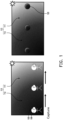
- FIG. 1 shows the scenario of rendering virtual objects based on the lighting information captured in an environment with uneven lighting.
- FIG. 1 if a user 199 wearing an AR device 100 is in an environment 110 having a brighter region 111 and a darker region 112, the lighting information obtained when the user 199 locates at the darker region 112 would be improper to be used when the user 199 moves to the brighter region 111. Specifically, when the virtual object 120 rendered based on the lighting information corresponding to the darker region 112 is seen by the user 199 at the brighter region 111, the rendered virtual object 120 would seem to be dark, which would be inconsistent with the brighter region 111 where the user locates.
- the lighting information obtained when the user 199 locates at the brighter region 111 would be improper to be used when the user 199 moves to the darker region 112.
- the virtual object rendered based on the lighting information corresponding to the brighter region 111 is seen by the user 199 at the darker region 112, the rendered virtual object would seem to be bright, which would be inconsistent with the darker region 112 where the user 199 locates.
- the disclosure is directed to a method for rendering a virtual object, a host, and a computer readable storage medium, which may be used to solve the above technical problems.
- the embodiments of the disclosure provide a method for rendering a virtual object, applied to a host, including: determining a plurality of regions in an environment; determining lighting information of each of the plurality of regions; obtaining a to-be-rendered virtual object and selecting at least one candidate region corresponding to the to-be-rendered virtual object among the plurality of regions; determining a reference lighting information based on the lighting information of each of the at least one candidate region; and rendering the to-be-rendered virtual object based on the reference lighting information.
- the embodiments of the disclosure provide a host including a storage circuit and a processor.
- the storage circuit stores a program code.
- the processor is coupled to the non-transitory storage circuit and accesses the program code to perform: determining a plurality of regions in an environment; determining lighting information of each of the plurality of regions; obtaining a to-be-rendered virtual object and selecting at least one candidate region corresponding to the to-be-rendered virtual object among the plurality of regions; determining a reference lighting information based on the lighting information of each of the at least one candidate region; and rendering the to-be-rendered virtual object based on the reference lighting information.
- the embodiments of the disclosure provide a non-transitory computer readable storage medium, the computer readable storage medium recording an executable computer program, the executable computer program being loaded by a host to perform steps of: determining a plurality of regions in an environment; determining lighting information of each of the plurality of regions; obtaining a to-be-rendered virtual object and selecting at least one candidate region corresponding to the to-be-rendered virtual object among the plurality of regions; determining a reference lighting information based on the lighting information of each of the at least one candidate region; and rendering the to-be-rendered virtual object based on the reference lighting information.
- the host 200 can be any smart device/computer device.
- the host 200 can be any electronic device capable of providing reality services (e.g., AR service, MR services, or the like).
- the host 200 can be implemented as an AR device, such as a pair of AR glasses and/or an HMD, but the disclosure is not limited thereto.
- the host 200 includes a storage circuit 202 and a processor 204.
- the storage circuit 202 is one or a combination of a stationary or mobile random access memory (RAM), read-only memory (ROM), flash memory, hard disk, or any other similar device, and which records a plurality of modules and/or a program code that can be executed by the processor 204.
- the processor 204 may be coupled with the storage circuit 202, and the processor 204 may be, for example, a general purpose processor, a special purpose processor, a conventional processor, a digital signal processor (DSP), a plurality of microprocessors, one or more microprocessors in association with a DSP core, a controller, a microcontroller, Application Specific Integrated Circuits (ASICs), Field Programmable Gate Array (FPGAs) circuits, any other type of integrated circuit (IC), a state machine, and the like.
- DSP digital signal processor
- ASICs Application Specific Integrated Circuits
- FPGAs Field Programmable Gate Array
- the host 200 can further include one or more camera 206 coupled to the processor 204.
- the camera 206 could be any camera having charge coupled device (CCD) lens, complementary metal oxide semiconductor transistors (CMOS) lens or infrared lens.
- CCD charge coupled device
- CMOS complementary metal oxide semiconductor transistors
- the camera 206 can be used to capture environmental images of the scene/environment where the host 200 locates, wherein the environmental images may be panoramas and/or cubemaps, but the disclosure is not limited thereto.
- the processor 204 may access the modules and/or the program code stored in the storage circuit 202 to implement the method for rendering a virtual object provided in the disclosure, which would be further discussed in the following.
- FIG. 3 shows a flow chart of the method for rendering a virtual object according to an embodiment of the disclosure.
- the method of this embodiment may be executed by the host 200 in FIG. 2 , and the details of each step in FIG. 3 will be described below with the components shown in FIG. 2 .
- the processor 204 can determine the regions in the environment based on the requirements of the designer.
- the processor 204 may scan the dimension/size/appearance of the environment and divide the environment into multiple 3D regions as the considered regions in step S310.
- the processor 204 may divide the environment into several 3D regions that are horizontally arranged in the environment.
- the processor 204 may divide the environment into several 3D regions arranged in grid.
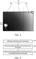
- FIG. 4 shows a schematic diagram of the determined regions in the environment according to an embodiment of the disclosure.
- the processor 204 may divide the environment 110 into, for example, 3D regions 110a-110c, but the disclosure is not limited thereto.
- the processor 204 may determine the regions according to the settings of the designer. For example, the designer may determine the dimension/size/appearance of the environment 110 and the size/position/dimension of each of the regions 110a-110c in advance, and the designer may input this information into the reality service system (e.g., AR system) of the host 200. In this case, the processor 204 may directly determine the regions 110a-110c according to the information inputted by the designer, but the disclosure is not limited thereto.
- the reality service system e.g., AR system
- FIG. 5 shows a flow chart of determining the lighting information for the first region according to an embodiment of the disclosure.
- step S610 in response to determining that the first environmental image is captured at a first location within the first region, the processor 204 determines a first relative position between the first location and the first reference point.
- step S620 the processor 204 calibrates the first environmental image based on the first relative position, wherein the calibrated first environmental image corresponds to a viewing angle of the host at the first reference point to the environment.
- the user 199 may wear an HMD as the corresponding host 200.
- the HMD of the user 199 may capture a first environmental image 620A at a first location L1 within the first region 610 (which may be understood as one of the regions 110a-110c).
- the viewing angle of the camera of the HMD of the user 199 may include a light source in the environment, such that the first environmental image 620A captures the light source, but the disclosure is not limited thereto.
- the processor 204 may determine a first relative position R1 between the first reference point 610a of the first region 610 and the first location L1 and calibrate the first environmental image 620A based on the first relative position R1.
- the calibrated first environmental image 630A corresponds to a viewing angle of the HMD of the user 199 at the first reference point 610a to the environment.
- the processor 204 determines the first lighting information of the first reference point as the lighting information of the first region.
- the processor 204 may accordingly determine the lighting information of a second region among the regions 110a-110c, wherein the second region may be adjacent to the first region.
- the region 110a since the user 199 is in the region 110a, the region 110a may be considered as the first region, and the region 110b adjacent to the region 110a may be considered as the second region.
- the processor 204 may determine the lighting information of the region 110b according to the lighting information of the region 110a after determining the lighting information of the region 110a.
- the processor 204 may directly determine the lighting information of the region 110b as the lighting information of the region 1 10a, or slightly modify the lighting information of the region 110a to generate the lighting information of the region 110b, but the disclosure is not limited thereto.
- the processor 204 may regard each of the regions 110a and 110c as the corresponding second region. In this case, the processor 204 may determine the lighting information of the regions 110a and 110c according to the lighting information of the region 110b. In one embodiment, the processor 204 may directly determine the lighting information of the regions 110a and 110c as the lighting information of the region 110b, or slightly modify the lighting information of the region 110b to generate the lighting information of the regions 110a and 110c based on, for example, the position, orientation of the host 200 and/or the geographical information of the environment 110, but the disclosure is not limited thereto.
- the processor 204 can update the lighting information of the region 110b via determining the lighting information again based on the above teachings, but the disclosure is not limited thereto.
- the to-be-rendered virtual object has a specific position in the visual content provided by the host 200 for the user 199 to see, wherein the specific position is the position where the virtual object will be displayed/shown after being rendered, but the disclosure is not limited thereto.
- the processor 204 can not only select the first region as the at least one candidate region, but can further select other regions near/adjacent to the first region as the at least one candidate region, such as the second region.
- the processor 204 may select the region 110b and the regions 110a and 110c (which are adjacent to the region 110b) as the at least one candidate region, but the disclosure is not limited thereto.
- step S340 the processor 204 determines a reference lighting information based on the lighting information of each of the at least one candidate region.
- the processor 204 may combine the lighting information of each of the at least one candidate region into the reference lighting information.
- the processor 204 may directly determine the reference lighting information as the lighting information of the region 110a.
- the processor 204 may combine the lighting information of each of the region 110a and 110b into the reference lighting information.
- the processor 204 may combine the lighting information of each of the at least one candidate region into the reference lighting information via performing a linear/non-linear/weighted combination to the lighting information of each of the at least one candidate region, but the disclosure is not limited thereto.
- the processor 204 can not only use the lighting information of the region where the host 200 currently locates in to determine the reference lighting information, but also can take the lighting information of other adjacent region into consideration when determining the reference lighting information.
- FIG. 7 shows an application scenario according to FIG. 4 .
- the host 200 can determine the lighting information of each of the regions 110a-110c when the user 199 moves from the regions 110a-110c.
- the processor 204 may determine the corresponding reference lighting information as the lighting information of the region 110a. In this case, the processor 204 may render the to-be-rendered virtual object 710 based on the corresponding reference lighting information (e.g., the lighting information of the region 110a) and display the rendered virtual object 710 at the corresponding specific position in the region 110a.
- the processor 204 can determine the reference lighting information corresponding to the to-be-rendered virtual object 710 via combining the lighting information of the region 110a and 110b since the to-be-rendered virtual object 710 is near the region 110b, but the disclosure is not limited thereto.
- the light on the rendered virtual object 710 can be consistent with the region 110a (which may be a dark region in the environment 110). More specifically, the rendered virtual object 710 would seem to be dark, which better matches the light situation of the region 110a.
- the processor 204 may determine the corresponding reference lighting information as the lighting information of the region 110b. In this case, the processor 204 may render the to-be-rendered virtual object 720 based on the corresponding reference lighting information (e.g., the lighting information of the region 110b) and display the rendered virtual object 720 at the corresponding specific position in the region 110b.
- the corresponding reference lighting information e.g., the lighting information of the region 110b
- the processor 204 can determine the reference lighting information corresponding to the to-be-rendered virtual object 720 via combining the lighting information of the region 110b with the lighting information of the region 110a and/or the lighting information of the region 110c since the to-be-rendered virtual object 720 is near the regions 110a and 110c, but the disclosure is not limited thereto.
- the light on the rendered virtual object 720 can be consistent with the region 110b (which may be a less dark region in the environment 110). More specifically, the rendered virtual object 720 would seem to be brighter than the rendered virtual object 710, which better matches the light situation of the region 110b since the region 110b is brighter than the region 110a.
- the processor 204 may determine the corresponding reference lighting information as the lighting information of the region 110c. In this case, the processor 204 may render the to-be-rendered virtual object 730 based on the corresponding reference lighting information (e.g., the lighting information of the region 110c) and display the rendered virtual object 730 at the corresponding specific position in the region 110c.
- the processor 204 can determine the reference lighting information corresponding to the to-be-rendered virtual object 730 via combining the lighting information of the region 110b and 110c since the to-be-rendered virtual object 730 is near the region 110b, but the disclosure is not limited thereto.
- the light on the rendered virtual object 730 can be consistent with the region 110c (which may be a bright region in the environment 110). More specifically, the rendered virtual object 730 would seem to be brighter than the rendered virtual object 720, which better matches the light situation of the region 110c since the region 110c is brighter than the region 110b.
- the processor 204 may store the obtained lighting information of each of the regions 110a-110c in, for example, a database associated with the environment 110. In this case, when the host 200 comes to the environment 110 for the next time, the processor 204 may directly retrieve the lighting information of each of the regions 110a-110c from the database, which may save the computing effort of the host 200.
- the disclosure further provides a computer readable storage medium for executing the method for rendering a virtual object.
- the computer readable storage medium is composed of a plurality of program instructions (for example, a setting program instruction and a deployment program instruction) embodied therein. These program instructions can be loaded into the host 200 and executed by the same to execute the method for rendering a virtual object and the functions of the host 200 described above.
- the embodiments of the disclosure provide a solution for better determining the corresponding lighting information of the to-be-rendered virtual object, such that the light on the rendered virtual object can be more consistent with the environment. Accordingly, the user may have a better visual experience.
Landscapes
- Engineering & Computer Science (AREA)
- Theoretical Computer Science (AREA)
- Physics & Mathematics (AREA)
- General Physics & Mathematics (AREA)
- Software Systems (AREA)
- Multimedia (AREA)
- Computer Graphics (AREA)
- General Engineering & Computer Science (AREA)
- Computer Hardware Design (AREA)
- Human Computer Interaction (AREA)
- Image Generation (AREA)
- Processing Or Creating Images (AREA)
Abstract
Description
- The present disclosure generally relates to mechanism for generating visual contents, in particular, to a method for rendering a virtual object, a host, and a computer readable storage medium.
- In reality services such as augmented reality (AR) or mixed reality (MR) services, the developers aim to seamlessly integrate virtual objects with the real world visually. To achieve this purpose, the reality system of the reality service needs to capture and store lighting information from the current scene/environment and use this stored lighting information to render virtual objects, such that the rendered virtual object can be looked like as being illuminated by the real environmental light.
- In the art, lighting information refers to data and details about the lighting conditions in the environment. Lighting information is a crucial component of AR/MR applications as it helps virtual objects appear more realistic, consistent, and lifelike within the real world.
- In general, lighting information encompasses the following aspects:
- (1) Light source position and direction: Understanding the location and direction of light sources, such as the sun, light bulbs, or other sources, to ensure that virtual objects' shadows and highlights align with the actual environment.
- (2) Light source intensity and color: Measuring the brightness and color of light sources to determine the color and brightness of virtual objects consistent with the surrounding environment.
- (3) Environment reflection and refraction: Taking into account the material and reflective properties of object surfaces to simulate how light interacts with the surfaces, achieving a more realistic appearance through reflection and refraction effects.
- (4) Shadows and occlusion: Generating appropriate shadow effects based on the light source's position and relationships between objects to make virtual objects look as if they belong in the real world.
- (5) Ambient lighting: Considering the overall lighting levels in the environment to adjust the brightness of virtual objects, making them blend seamlessly with their surroundings.
- In brief, lighting information in AR/MR applications is used to ensure that virtual objects are presented in a manner that harmonizes with the real-world environment, enhancing user perception and experience. This involves complex calculations and algorithms to simulate the behavior of light rays and the interaction of virtual objects with light, achieving high-quality augmented reality effects.
- Typically, AR systems collect lighting information through cameras on AR devices (e.g., a head-mounted display (HMD) and/or a pair of AR glasses). Since light can come from any angle in the environment, the AR system needs to guide the user to look around the entire scene/environment, such that the AR device can collect complete lighting information of the entire scene/environment. Under this premise, when the lighting of the scene/environment changes for some reasons (e.g., the lights are turned on or off), the user needs to perform the above action (i.e., looking around the scene/environment) again to update the lighting information of the scene/environment.
- Moreover, when the lighting in the environment is uneven, the AR device cannot obtain the complete lighting information by the user only looking around for once. This is because a single capture position cannot reflect the uneven lighting of the entire environment.
- See
FIG. 1 , which shows the scenario of rendering virtual objects based on the lighting information captured in an environment with uneven lighting. - In
FIG. 1 , if auser 199 wearing anAR device 100 is in anenvironment 110 having abrighter region 111 and adarker region 112, the lighting information obtained when theuser 199 locates at thedarker region 112 would be improper to be used when theuser 199 moves to thebrighter region 111. Specifically, when thevirtual object 120 rendered based on the lighting information corresponding to thedarker region 112 is seen by theuser 199 at thebrighter region 111, the renderedvirtual object 120 would seem to be dark, which would be inconsistent with thebrighter region 111 where the user locates. - Likewise, the lighting information obtained when the
user 199 locates at thebrighter region 111 would be improper to be used when theuser 199 moves to thedarker region 112. Specifically, when the virtual object rendered based on the lighting information corresponding to thebrighter region 111 is seen by theuser 199 at thedarker region 112, the rendered virtual object would seem to be bright, which would be inconsistent with thedarker region 112 where theuser 199 locates. - Accordingly, the disclosure is directed to a method for rendering a virtual object, a host, and a computer readable storage medium, which may be used to solve the above technical problems.
- The embodiments of the disclosure provide a method for rendering a virtual object, applied to a host, including: determining a plurality of regions in an environment; determining lighting information of each of the plurality of regions; obtaining a to-be-rendered virtual object and selecting at least one candidate region corresponding to the to-be-rendered virtual object among the plurality of regions; determining a reference lighting information based on the lighting information of each of the at least one candidate region; and rendering the to-be-rendered virtual object based on the reference lighting information.
- The embodiments of the disclosure provide a host including a storage circuit and a processor. The storage circuit stores a program code. The processor is coupled to the non-transitory storage circuit and accesses the program code to perform: determining a plurality of regions in an environment; determining lighting information of each of the plurality of regions; obtaining a to-be-rendered virtual object and selecting at least one candidate region corresponding to the to-be-rendered virtual object among the plurality of regions; determining a reference lighting information based on the lighting information of each of the at least one candidate region; and rendering the to-be-rendered virtual object based on the reference lighting information.
- The embodiments of the disclosure provide a non-transitory computer readable storage medium, the computer readable storage medium recording an executable computer program, the executable computer program being loaded by a host to perform steps of: determining a plurality of regions in an environment; determining lighting information of each of the plurality of regions; obtaining a to-be-rendered virtual object and selecting at least one candidate region corresponding to the to-be-rendered virtual object among the plurality of regions; determining a reference lighting information based on the lighting information of each of the at least one candidate region; and rendering the to-be-rendered virtual object based on the reference lighting information.
- The accompanying drawings are included to provide a further understanding of the invention, and are incorporated in and constitute a part of this specification. The drawings illustrate embodiments of the invention and, together with the description, serve to explain the principles of the disclosure.
-
FIG. 1 shows the scenario of rendering virtual objects based on the lighting information captured in an environment with uneven lighting. -
FIG. 2 shows a schematic diagram of a host according to an embodiment of the disclosure. -
FIG. 3 shows a flow chart of the method for rendering a virtual object according to an embodiment of the disclosure. -
FIG. 4 shows a schematic diagram of the determined regions in the environment according to an embodiment of the disclosure. -
FIG. 5 shows a flow chart of determining the lighting information for the first region according to an embodiment of the disclosure. -
FIG. 6A shows a flow chart of determining the first lighting information of the first reference point according to an embodiment of the disclosure. -
FIG. 6B shows an application scenario according toFIG. 6A . -
FIG. 7 shows an application scenario according toFIG. 4 . - Reference will now be made in detail to the present preferred embodiments of the invention, examples of which are illustrated in the accompanying drawings. Wherever possible, the same reference numbers are used in the drawings and the description to refer to the same or like parts.
- See
FIG. 2 , which shows a schematic diagram of a host according to an embodiment of the disclosure. In various embodiments, thehost 200 can be any smart device/computer device. In some embodiments, thehost 200 can be any electronic device capable of providing reality services (e.g., AR service, MR services, or the like). In some embodiments, thehost 200 can be implemented as an AR device, such as a pair of AR glasses and/or an HMD, but the disclosure is not limited thereto. - In
FIG. 2 , thehost 200 includes astorage circuit 202 and aprocessor 204. Thestorage circuit 202 is one or a combination of a stationary or mobile random access memory (RAM), read-only memory (ROM), flash memory, hard disk, or any other similar device, and which records a plurality of modules and/or a program code that can be executed by theprocessor 204. - The
processor 204 may be coupled with thestorage circuit 202, and theprocessor 204 may be, for example, a general purpose processor, a special purpose processor, a conventional processor, a digital signal processor (DSP), a plurality of microprocessors, one or more microprocessors in association with a DSP core, a controller, a microcontroller, Application Specific Integrated Circuits (ASICs), Field Programmable Gate Array (FPGAs) circuits, any other type of integrated circuit (IC), a state machine, and the like. - In some embodiments, the
host 200 can further include one ormore camera 206 coupled to theprocessor 204. Thecamera 206 could be any camera having charge coupled device (CCD) lens, complementary metal oxide semiconductor transistors (CMOS) lens or infrared lens. In the embodiments of the disclosure, thecamera 206 can be used to capture environmental images of the scene/environment where thehost 200 locates, wherein the environmental images may be panoramas and/or cubemaps, but the disclosure is not limited thereto. - In the embodiments of the disclosure, the
processor 204 may access the modules and/or the program code stored in thestorage circuit 202 to implement the method for rendering a virtual object provided in the disclosure, which would be further discussed in the following. - See
FIG. 3 , which shows a flow chart of the method for rendering a virtual object according to an embodiment of the disclosure. The method of this embodiment may be executed by thehost 200 inFIG. 2 , and the details of each step inFIG. 3 will be described below with the components shown inFIG. 2 . - In step S310, the
processor 204 determines a plurality of regions in an environment. In one embodiment, the environment may be the scene/field where thehost 200 and the user thereof locates, such as a room, a house, a gallery, but the disclosure is not limited thereto. - In one embodiment, the
processor 204 can determine the regions in the environment based on the requirements of the designer. - For example, the
processor 204 may scan the dimension/size/appearance of the environment and divide the environment into multiple 3D regions as the considered regions in step S310. - In one embodiment, since the user would more likely to move horizontally in the environment, the
processor 204 may divide the environment into several 3D regions that are horizontally arranged in the environment. - In one embodiment, the
processor 204 may divide the environment into several 3D regions arranged in grid. - In one embodiment, if the environment is disposed with one or more landmarks (e.g., furniture or other real objects), the
processor 204 may divide the environment into the regions based on the landmarks. - See
FIG. 4 , which shows a schematic diagram of the determined regions in the environment according to an embodiment of the disclosure. InFIG. 4 , after theprocessor 204 obtains the dimension/size/appearance of theenvironment 100, theprocessor 204 may divide theenvironment 110 into, for example,3D regions 110a-110c, but the disclosure is not limited thereto. - In one embodiment, the
processor 204 may determine the regions according to the settings of the designer. For example, the designer may determine the dimension/size/appearance of theenvironment 110 and the size/position/dimension of each of theregions 110a-110c in advance, and the designer may input this information into the reality service system (e.g., AR system) of thehost 200. In this case, theprocessor 204 may directly determine theregions 110a-110c according to the information inputted by the designer, but the disclosure is not limited thereto. - For better understanding the concept of the disclosure, the application scenario in
FIG. 4 would be used as an illustrative example, but the disclosure is not limited thereto. - In step S320, the
processor 204 determine lighting information of each of the plurality ofregions 110a-110c. - In one embodiment, the
processor 204 may perform steps inFIG. 5 for determining the lighting information for a first region in theregions 110a-110c. - See
FIG. 5 , which shows a flow chart of determining the lighting information for the first region according to an embodiment of the disclosure. - In step S510, the
processor 204 determines a first reference point in the first region. In various embodiments, the first reference point can be any point locating within the first region, such as the center point of the first region, but the disclosure is not limited thereto. - In step S520, the
processor 204 determines first lighting information of the first reference point in the first region. - In one embodiment, in response to determining that the
host 200 locates in the first region, theprocessor 204 may control thecamera 206 to capture a first environmental image associated with the first region, wherein the first environmental image may include at least one of a panorama and a cubemap. Next theprocessor 204 may determine the first lighting information of the first reference point in the first region based on the first environmental image associated with the first region. - In one embodiment, the
processor 204 may perform steps inFIG. 6A for determining the first lighting information of the first reference point in the first region based on the first environmental image associated with the first region. - See
FIG. 6A , which shows a flow chart of determining the first lighting information of the first reference point according to an embodiment of the disclosure. - In step S610, in response to determining that the first environmental image is captured at a first location within the first region, the
processor 204 determines a first relative position between the first location and the first reference point. - In step S620, the
processor 204 calibrates the first environmental image based on the first relative position, wherein the calibrated first environmental image corresponds to a viewing angle of the host at the first reference point to the environment. - In step S630, the
processor 204 converts the calibrated first environmental image into the first lighting information of the first reference point. - For better understanding the concept of
FIG. 6A, FIG. 6B would be used as an illustrative example, whereinFIG. 6B shows an application scenario according toFIG. 6A . - In
FIG. 6B , theuser 199 may wear an HMD as thecorresponding host 200. In the embodiment, the HMD of theuser 199 may capture a firstenvironmental image 620A at a first location L1 within the first region 610 (which may be understood as one of theregions 110a-110c). InFIG. 6B , the viewing angle of the camera of the HMD of theuser 199 may include a light source in the environment, such that the firstenvironmental image 620A captures the light source, but the disclosure is not limited thereto. - In this case, the
processor 204 may determine a first relative position R1 between thefirst reference point 610a of thefirst region 610 and the first location L1 and calibrate the firstenvironmental image 620A based on the first relative position R1. As shown inFIG. 6B , the calibrated firstenvironmental image 630A corresponds to a viewing angle of the HMD of theuser 199 at thefirst reference point 610a to the environment. - After obtaining the calibrated first
environmental image 620A, the HMD may convert the calibrated firstenvironmental image 620A into the first lighting information of thefirst reference point 610a. - In another embodiment, the HMD of the
user 199 may capture a firstenvironmental image 620B at a first location L2 within the first region 610 (which may be understood as one of theregions 110a-110c). InFIG. 6B , the viewing angle of the camera of the HMD of theuser 199 may also include the light source in the environment, such that the firstenvironmental image 620B captures the light source, but the disclosure is not limited thereto. - In this case, the
processor 204 may determine a first relative position R2 between thefirst reference point 610a of thefirst region 610 and the first location L2 and calibrate the firstenvironmental image 620B based on the first relative position R2. As shown inFIG. 6B , the calibrated firstenvironmental image 630B corresponds to a viewing angle of the HMD of theuser 199 at thefirst reference point 610a to the environment. - After obtaining the calibrated first
environmental image 620B, the HMD may convert the calibrated firstenvironmental image 620B into the first lighting information of thefirst reference point 610a. - Referring back to
FIG. 5 , after determining the first lighting information of the first reference point (e.g., thefirst reference point 610a) in the first region (e.g., the first region 610), theprocessor 204 determines the first lighting information of the first reference point as the lighting information of the first region. - In one embodiment, the
processor 204 may determine the lighting information for each of theregions 110a-110c based on the descriptions in the above. - In one embodiment, once the lighting information of the first region is determined, the
processor 204 may accordingly determine the lighting information of a second region among theregions 110a-110c, wherein the second region may be adjacent to the first region. - Taking the scenario in
FIG. 4 as an example, since theuser 199 is in theregion 110a, theregion 110a may be considered as the first region, and theregion 110b adjacent to theregion 110a may be considered as the second region. In this case, theprocessor 204 may determine the lighting information of theregion 110b according to the lighting information of theregion 110a after determining the lighting information of theregion 110a. In one embodiment, theprocessor 204 may directly determine the lighting information of theregion 110b as the lighting information of theregion 1 10a, or slightly modify the lighting information of theregion 110a to generate the lighting information of theregion 110b, but the disclosure is not limited thereto. - In one embodiment, the
processor 204 may update the lighting information of at least one of theregions 110a-110c in response to the movement of thehost 200. For example, when theuser 199 moves from theregion 110a to theregion 110b, theprocessor 204 may further update the lighting information of theregion 110b based on the descriptions associated withFIGs. 5 ,6A, and 6B . - Since the
region 110b can be seen as adjacent to theregions processor 204 may regard each of theregions processor 204 may determine the lighting information of theregions region 110b. In one embodiment, theprocessor 204 may directly determine the lighting information of theregions region 110b, or slightly modify the lighting information of theregion 110b to generate the lighting information of theregions host 200 and/or the geographical information of theenvironment 110, but the disclosure is not limited thereto. - In some embodiments, the
processor 204 can individually determine the lighting information of each of theregions 110a-110c. For example, when theuser 199 is in theregion 110a, theprocessor 204 can merely determine the lighting information of theregion 110a based on the above discussions. When theuser 199 moves from theregion 110a to theregion 110b, theprocessor 204 can merely determine the lighting information of theregion 110b based on the above discussions. When theuser 199 moves from theregion 110b to theregion 110c, theprocessor 204 can merely determine the lighting information of theregion 110c based on the above discussions. - In one embodiment, if the
user 199 moves from theregion 110c back to theregion 110b, theprocessor 204 can update the lighting information of theregion 110b via determining the lighting information again based on the above teachings, but the disclosure is not limited thereto. - Referring back to
FIG. 3 , after determining the lighting information of each of theregions 110a-110c, theprocessor 204 performs step S330 to obtain a to-be-rendered virtual object and selecting at least one candidate region corresponding to the to-be-rendered virtual object among the plurality of regions. - In one embodiment, the to-be-rendered virtual object may be, for example, an AR object, which will be rendered for the
user 199 to see. - In one embodiment, the to-be-rendered virtual object has a specific position in the visual content provided by the
host 200 for theuser 199 to see, wherein the specific position is the position where the virtual object will be displayed/shown after being rendered, but the disclosure is not limited thereto. - In the embodiments of the disclosure, the
processor 204 can select at least one candidate region corresponding to the to-be-rendered virtual object among theregions 110a-110c. - In one embodiment, in response to determining that the to-be-rendered virtual object locates in the first region (i.e., the specific position of the to-be-rendered virtual object is within the first region), the
processor 204 can at least select the first region as the at least one candidate region. - For example, if the to-be-rendered virtual object locates in the
region 110a, theprocessor 204 may at least select theregion 110a as one of the at least one candidate region. - In addition, in response to determining that the to-be-rendered virtual object locates in the first region (i.e., the specific position of the to-be-rendered virtual object is within the first region), the
processor 204 can not only select the first region as the at least one candidate region, but can further select other regions near/adjacent to the first region as the at least one candidate region, such as the second region. - For example, if the to-be-rendered virtual object locates in the
region 110a, theprocessor 204 may select theregion 110a and theregion 110b (which is adjacent to theregion 110a) as the at least one candidate region. - For another example, if the to-be-rendered virtual object locates in the
region 1 10b, theprocessor 204 may select theregion 110b and theregions region 110b) as the at least one candidate region, but the disclosure is not limited thereto. - In step S340, the
processor 204 determines a reference lighting information based on the lighting information of each of the at least one candidate region. - In one embodiment, the
processor 204 may combine the lighting information of each of the at least one candidate region into the reference lighting information. - For example, if the
processor 204 determines that the at least one candidate region includes theregion 110a, theprocessor 204 may directly determine the reference lighting information as the lighting information of theregion 110a. - For another example, if the
processor 204 determines that the at least one candidate region includes theregion processor 204 may combine the lighting information of each of theregion - In one embodiment, the
processor 204 may combine the lighting information of each of the at least one candidate region into the reference lighting information via performing a linear/non-linear/weighted combination to the lighting information of each of the at least one candidate region, but the disclosure is not limited thereto. - From another perspective, the
processor 204 can not only use the lighting information of the region where thehost 200 currently locates in to determine the reference lighting information, but also can take the lighting information of other adjacent region into consideration when determining the reference lighting information. - In step S350, the
processor 204 renders the to-be-rendered virtual object based on the reference lighting information. In the embodiment, since the reference lighting information can better characterize the lighting information corresponding to the to-be-rendered virtual object, the light on the rendered virtual object would be more consistent with the environment. - See
FIG. 7 , which shows an application scenario according toFIG. 4 . InFIG. 7 , thehost 200 can determine the lighting information of each of theregions 110a-110c when theuser 199 moves from theregions 110a-110c. - In one embodiment, for a to-be-rendered
virtual object 710 locates in theregion 110a (e.g., thevirtual object 710 is expected to be shown/displayed within theregion 110a after being rendered), theprocessor 204 may determine the corresponding reference lighting information as the lighting information of theregion 110a. In this case, theprocessor 204 may render the to-be-renderedvirtual object 710 based on the corresponding reference lighting information (e.g., the lighting information of theregion 110a) and display the renderedvirtual object 710 at the corresponding specific position in theregion 110a. - In another embodiment, the
processor 204 can determine the reference lighting information corresponding to the to-be-renderedvirtual object 710 via combining the lighting information of theregion virtual object 710 is near theregion 110b, but the disclosure is not limited thereto. - As shown in
FIG. 7 , the light on the renderedvirtual object 710 can be consistent with theregion 110a (which may be a dark region in the environment 110). More specifically, the renderedvirtual object 710 would seem to be dark, which better matches the light situation of theregion 110a. - In one embodiment, for a to-be-rendered
virtual object 720 locates in theregion 110b (e.g., thevirtual object 720 is expected to be shown/displayed within theregion 110b after being rendered), theprocessor 204 may determine the corresponding reference lighting information as the lighting information of theregion 110b. In this case, theprocessor 204 may render the to-be-renderedvirtual object 720 based on the corresponding reference lighting information (e.g., the lighting information of theregion 110b) and display the renderedvirtual object 720 at the corresponding specific position in theregion 110b. - In another embodiment, the
processor 204 can determine the reference lighting information corresponding to the to-be-renderedvirtual object 720 via combining the lighting information of theregion 110b with the lighting information of theregion 110a and/or the lighting information of theregion 110c since the to-be-renderedvirtual object 720 is near theregions - As shown in
FIG. 7 , the light on the renderedvirtual object 720 can be consistent with theregion 110b (which may be a less dark region in the environment 110). More specifically, the renderedvirtual object 720 would seem to be brighter than the renderedvirtual object 710, which better matches the light situation of theregion 110b since theregion 110b is brighter than theregion 110a. - In one embodiment, for a to-be-rendered
virtual object 730 locates in theregion 110c (e.g., thevirtual object 730 is expected to be shown/displayed within theregion 110c after being rendered), theprocessor 204 may determine the corresponding reference lighting information as the lighting information of theregion 110c. In this case, theprocessor 204 may render the to-be-renderedvirtual object 730 based on the corresponding reference lighting information (e.g., the lighting information of theregion 110c) and display the renderedvirtual object 730 at the corresponding specific position in theregion 110c. - In another embodiment, the
processor 204 can determine the reference lighting information corresponding to the to-be-renderedvirtual object 730 via combining the lighting information of theregion virtual object 730 is near theregion 110b, but the disclosure is not limited thereto. - As shown in
FIG. 7 , the light on the renderedvirtual object 730 can be consistent with theregion 110c (which may be a bright region in the environment 110). More specifically, the renderedvirtual object 730 would seem to be brighter than the renderedvirtual object 720, which better matches the light situation of theregion 110c since theregion 110c is brighter than theregion 110b. - In some embodiments, the
processor 204 may store the obtained lighting information of each of theregions 110a-110c in, for example, a database associated with theenvironment 110. In this case, when thehost 200 comes to theenvironment 110 for the next time, theprocessor 204 may directly retrieve the lighting information of each of theregions 110a-110c from the database, which may save the computing effort of thehost 200. - The disclosure further provides a computer readable storage medium for executing the method for rendering a virtual object. The computer readable storage medium is composed of a plurality of program instructions (for example, a setting program instruction and a deployment program instruction) embodied therein. These program instructions can be loaded into the
host 200 and executed by the same to execute the method for rendering a virtual object and the functions of thehost 200 described above. - To sum up, the embodiments of the disclosure provide a solution for better determining the corresponding lighting information of the to-be-rendered virtual object, such that the light on the rendered virtual object can be more consistent with the environment. Accordingly, the user may have a better visual experience.
- It will be apparent to those skilled in the art that various modifications and variations can be made to the structure of the present invention without departing from the scope or spirit of the disclosure. In view of the foregoing, it is intended that the present disclosure cover modifications and variations of this invention provided they fall within the scope of the following claims and their equivalents.
Claims (15)
- A method for rendering a virtual object, applied to a host, comprising:determining, by the host, a plurality of regions in an environment;determining, by the host, lighting information of each of the plurality of regions;obtaining, by the host, a to-be-rendered virtual object and selecting, by the host, at least one candidate region corresponding to the to-be-rendered virtual object among the plurality of regions;determining, by the host, a reference lighting information based on the lighting information of each of the at least one candidate region; andrendering, by the host, the to-be-rendered virtual object based on the reference lighting information.
- The method according to claim 1, further comprising:
updating the lighting information of at least one of the plurality of regions in response to a movement of the host. - The method according to claim 1, wherein the plurality of regions comprise a first region, and the step of determining the lighting information of each of the plurality of regions comprises:determining a first reference point in the first region;determining first lighting information of the first reference point in the first region; anddetermining the first lighting information of the first reference point as the lighting information of the first region.
- The method according to claim 3, wherein the first reference point in the first region is a center point of the first region.
- The method according to claim 3, wherein the step of determining the first lighting information of the first reference point in the first region comprises:in response to determining that the host locates in the first region, capturing a first environmental image associated with the first region, wherein the first environmental image comprises at least one of a panorama and a cubemap; anddetermining the first lighting information of the first reference point in the first region based on the first environmental image associated with the first region.
- The method according to claim 5, wherein the step of determining the first lighting information of the first reference point in the first region based on the first environmental image associated with the first region comprises:in response to determining that the first environmental image is captured at a first location within the first region, determining a first relative position between the first location and the first reference point;calibrating the first environmental image based on the first relative position, wherein the calibrated first environmental image corresponds to a viewing angle of the host at the first reference point to the environment; andconverting the calibrated first environmental image into the first lighting information of the first reference point.
- The method according to claim 3, wherein the plurality of regions comprise a first region and a second region adjacent to each other, and the method further comprises:
after determining the lighting information of the first region, accordingly determining the lighting information of the second region. - The method according to claim 1, wherein the plurality of regions comprise a first region, and the step of selecting the at least one candidate region corresponding to the to-be-rendered virtual object among the plurality of regions comprises:
in response to determining that the to-be-rendered virtual object locates in the first region, at least selecting the first region as the at least one candidate region. - The method according to claim 8, wherein the plurality of regions further comprise a second region adjacent to the first region, and the step of at least selecting the first region as the at least one candidate region comprises:
selecting the first region and the second region as the at least one candidate region. - The method according to claim 1, wherein the step of determining the reference lighting information based on the lighting information of each of the at least one candidate region comprises:
combining the lighting information of each of the at least one candidate region into the reference lighting information. - A host, comprising:a non-transitory storage circuit, storing a program code; anda processor, coupled to the non-transitory storage circuit and accessing the program code to perform:determining a plurality of regions in an environment;determining lighting information of each of the plurality of regions;obtaining a to-be-rendered virtual object and selecting at least one candidate region corresponding to the to-be-rendered virtual object among the plurality of regions;determining a reference lighting information based on the lighting information of each of the at least one candidate region; andrendering the to-be-rendered virtual object based on the reference lighting information.
- The host according to claim 11, wherein the processor further performs:
updating the lighting information of at least one of the plurality of regions in response to a movement of the host. - The host according to claim 11, wherein the plurality of regions comprise a first region, and the processor performs:determining a first reference point in the first region;determining first lighting information of the first reference point in the first region; anddetermining the first lighting information of the first reference point as the lighting information of the first region.
- The host according to claim 13, wherein the first reference point in the first region is a center point of the first region.
- A non-transitory computer readable storage medium, the computer readable storage medium recording an executable computer program, the executable computer program being loaded by a host to perform steps of:determining a plurality of regions in an environment;determining lighting information of each of the plurality of regions;obtaining a to-be-rendered virtual object and selecting at least one candidate region corresponding to the to-be-rendered virtual object among the plurality of regions;determining a reference lighting information based on the lighting information of each of the at least one candidate region; andrendering the to-be-rendered virtual object based on the reference lighting information.
Applications Claiming Priority (1)
| Application Number | Priority Date | Filing Date | Title |
|---|---|---|---|
| US18/463,320 US12633066B2 (en) | 2023-09-08 | 2023-09-08 | Method for rendering virtual object, host, and computer readable storage medium |
Publications (3)
| Publication Number | Publication Date |
|---|---|
| EP4521206A1 true EP4521206A1 (en) | 2025-03-12 |
| EP4521206C0 EP4521206C0 (en) | 2025-10-15 |
| EP4521206B1 EP4521206B1 (en) | 2025-10-15 |
Family
ID=90880736
Family Applications (1)
| Application Number | Title | Priority Date | Filing Date |
|---|---|---|---|
| EP24172284.2A Active EP4521206B1 (en) | 2023-09-08 | 2024-04-24 | Method for rendering virtual object, host, and computer readable storage medium |
Country Status (4)
| Country | Link |
|---|---|
| US (1) | US12633066B2 (en) |
| EP (1) | EP4521206B1 (en) |
| CN (1) | CN119600165A (en) |
| TW (1) | TWI872754B (en) |
Citations (3)
| Publication number | Priority date | Publication date | Assignee | Title |
|---|---|---|---|---|
| US10777010B1 (en) * | 2018-03-16 | 2020-09-15 | Amazon Technologies, Inc. | Dynamic environment mapping for augmented reality |
| US20210279972A1 (en) * | 2019-06-27 | 2021-09-09 | Facebook Technologies, Llc | Adjusted overlaid images in scenes |
| US20230260228A1 (en) * | 2022-02-17 | 2023-08-17 | Meta Platforms Technologies, Llc | Adaptive mixed reality |
Family Cites Families (5)
| Publication number | Priority date | Publication date | Assignee | Title |
|---|---|---|---|---|
| CN110070621B (en) | 2018-01-19 | 2023-04-07 | 宏达国际电子股份有限公司 | Electronic device, method for displaying augmented reality scene, and computer-readable medium |
| CN111127624A (en) | 2019-12-27 | 2020-05-08 | 珠海金山网络游戏科技有限公司 | Illumination rendering method and device based on AR scene |
| CN115769268A (en) | 2020-06-22 | 2023-03-07 | 谷歌有限责任公司 | Depth-based relighting in augmented reality |
| US11495004B1 (en) * | 2021-06-15 | 2022-11-08 | Meta Platforms Technologies, Llc | Systems and methods for lighting subjects for artificial reality scenes |
| CN113552942B (en) | 2021-07-14 | 2024-08-30 | 海信视像科技股份有限公司 | Method and device for displaying virtual objects based on light intensity |
-
2023
- 2023-09-08 US US18/463,320 patent/US12633066B2/en active Active
- 2023-10-25 TW TW112140740A patent/TWI872754B/en active
- 2023-12-08 CN CN202311684385.3A patent/CN119600165A/en active Pending
-
2024
- 2024-04-24 EP EP24172284.2A patent/EP4521206B1/en active Active
Patent Citations (3)
| Publication number | Priority date | Publication date | Assignee | Title |
|---|---|---|---|---|
| US10777010B1 (en) * | 2018-03-16 | 2020-09-15 | Amazon Technologies, Inc. | Dynamic environment mapping for augmented reality |
| US20210279972A1 (en) * | 2019-06-27 | 2021-09-09 | Facebook Technologies, Llc | Adjusted overlaid images in scenes |
| US20230260228A1 (en) * | 2022-02-17 | 2023-08-17 | Meta Platforms Technologies, Llc | Adaptive mixed reality |
Also Published As
| Publication number | Publication date |
|---|---|
| US20250086902A1 (en) | 2025-03-13 |
| CN119600165A (en) | 2025-03-11 |
| EP4521206C0 (en) | 2025-10-15 |
| US12633066B2 (en) | 2026-05-19 |
| EP4521206B1 (en) | 2025-10-15 |
| TW202512109A (en) | 2025-03-16 |
| TWI872754B (en) | 2025-02-11 |
Similar Documents
| Publication | Publication Date | Title |
|---|---|---|
| US11887251B2 (en) | System and techniques for patch color correction for an immersive content production system | |
| US11182961B2 (en) | Method and system for representing a virtual object in a view of a real environment | |
| US11978154B2 (en) | System and techniques for lighting adjustment for an immersive content production system | |
| CN111260769B (en) | Real-time rendering method and device based on dynamic illumination change | |
| CN111833423A (en) | Presentation method, presentation device, presentation equipment and computer-readable storage medium | |
| US9183654B2 (en) | Live editing and integrated control of image-based lighting of 3D models | |
| US12373999B2 (en) | User interfaces for color and lighting adjustments for an immersive content production system | |
| CN109427089B (en) | Mixed reality object rendering based on ambient lighting conditions | |
| US11762481B2 (en) | Light capture device | |
| EP2933781A2 (en) | Method and system for representing a virtual object in a view of a real environment | |
| CN113110731B (en) | Method and device for generating media content | |
| CN111862339A (en) | Virtual label display method, device, equipment and computer readable storage medium | |
| US20240161390A1 (en) | Method, apparatus, electronic device and storage medium for control based on extended reality | |
| JP2015099545A (en) | Image generation system and image generation program | |
| US20240331103A1 (en) | Method for training light filling model, image processing method, and related device thereof | |
| CN111077671A (en) | Device control method, device, display device and storage medium | |
| CN112219218B (en) | Methods and electronic devices for recommending image capture modes | |
| EP4521206B1 (en) | Method for rendering virtual object, host, and computer readable storage medium | |
| CA3157013C (en) | Color and lighting adjustment for immersive content production system | |
| CN117676111A (en) | A display method, device and equipment for extended reality images | |
| CN108932750A (en) | Methods of exhibiting, device, electronic equipment and the storage medium of augmented reality | |
| CN119255117B (en) | Image processing method based on color temperature rendering, electronic device and related medium | |
| HK40085305A (en) | Color and lighting adjustment for immersive content production system |
Legal Events
| Date | Code | Title | Description |
|---|---|---|---|
| PUAI | Public reference made under article 153(3) epc to a published international application that has entered the european phase |
Free format text: ORIGINAL CODE: 0009012 |
|
| STAA | Information on the status of an ep patent application or granted ep patent |
Free format text: STATUS: EXAMINATION IS IN PROGRESS |
|
| 17P | Request for examination filed |
Effective date: 20240424 |
|
| AK | Designated contracting states |
Kind code of ref document: A1 Designated state(s): AL AT BE BG CH CY CZ DE DK EE ES FI FR GB GR HR HU IE IS IT LI LT LU LV MC ME MK MT NL NO PL PT RO RS SE SI SK SM TR |
|
| GRAP | Despatch of communication of intention to grant a patent |
Free format text: ORIGINAL CODE: EPIDOSNIGR1 |
|
| STAA | Information on the status of an ep patent application or granted ep patent |
Free format text: STATUS: GRANT OF PATENT IS INTENDED |
|
| RIC1 | Information provided on ipc code assigned before grant |
Ipc: G06F 3/01 20060101AFI20250626BHEP Ipc: G06T 15/50 20110101ALI20250626BHEP Ipc: G06T 19/00 20110101ALI20250626BHEP Ipc: G06V 10/60 20220101ALI20250626BHEP Ipc: G06V 10/25 20220101ALI20250626BHEP |
|
| INTG | Intention to grant announced |
Effective date: 20250709 |
|
| GRAS | Grant fee paid |
Free format text: ORIGINAL CODE: EPIDOSNIGR3 |
|
| GRAA | (expected) grant |
Free format text: ORIGINAL CODE: 0009210 |
|
| STAA | Information on the status of an ep patent application or granted ep patent |
Free format text: STATUS: THE PATENT HAS BEEN GRANTED |
|
| AK | Designated contracting states |
Kind code of ref document: B1 Designated state(s): AL AT BE BG CH CY CZ DE DK EE ES FI FR GB GR HR HU IE IS IT LI LT LU LV MC ME MK MT NL NO PL PT RO RS SE SI SK SM TR |
|
| REG | Reference to a national code |
Ref country code: GB Ref legal event code: FG4D Ref country code: CH Ref legal event code: F10 Free format text: ST27 STATUS EVENT CODE: U-0-0-F10-F00 (AS PROVIDED BY THE NATIONAL OFFICE) Effective date: 20251015 |
|
| REG | Reference to a national code |
Ref country code: IE Ref legal event code: FG4D |
|
| REG | Reference to a national code |
Ref country code: DE Ref legal event code: R096 Ref document number: 602024000920 Country of ref document: DE |
|
| U01 | Request for unitary effect filed |
Effective date: 20251112 |
|
| U07 | Unitary effect registered |
Designated state(s): AT BE BG DE DK EE FI FR IT LT LU LV MT NL PT RO SE SI Effective date: 20251118 |
|
| PG25 | Lapsed in a contracting state [announced via postgrant information from national office to epo] |
Ref country code: ES Free format text: LAPSE BECAUSE OF FAILURE TO SUBMIT A TRANSLATION OF THE DESCRIPTION OR TO PAY THE FEE WITHIN THE PRESCRIBED TIME-LIMIT Effective date: 20251015 |
|
| PG25 | Lapsed in a contracting state [announced via postgrant information from national office to epo] |
Ref country code: NO Free format text: LAPSE BECAUSE OF FAILURE TO SUBMIT A TRANSLATION OF THE DESCRIPTION OR TO PAY THE FEE WITHIN THE PRESCRIBED TIME-LIMIT Effective date: 20260115 |
|
| PG25 | Lapsed in a contracting state [announced via postgrant information from national office to epo] |
Ref country code: HR Free format text: LAPSE BECAUSE OF FAILURE TO SUBMIT A TRANSLATION OF THE DESCRIPTION OR TO PAY THE FEE WITHIN THE PRESCRIBED TIME-LIMIT Effective date: 20251015 |
|
| U20 | Renewal fee for the european patent with unitary effect paid |
Year of fee payment: 3 Effective date: 20260310 |
|
| PG25 | Lapsed in a contracting state [announced via postgrant information from national office to epo] |
Ref country code: RS Free format text: LAPSE BECAUSE OF FAILURE TO SUBMIT A TRANSLATION OF THE DESCRIPTION OR TO PAY THE FEE WITHIN THE PRESCRIBED TIME-LIMIT Effective date: 20260115 |
|
| PG25 | Lapsed in a contracting state [announced via postgrant information from national office to epo] |
Ref country code: IS Free format text: LAPSE BECAUSE OF FAILURE TO SUBMIT A TRANSLATION OF THE DESCRIPTION OR TO PAY THE FEE WITHIN THE PRESCRIBED TIME-LIMIT Effective date: 20260215 |
|
| PG25 | Lapsed in a contracting state [announced via postgrant information from national office to epo] |
Ref country code: PL Free format text: LAPSE BECAUSE OF FAILURE TO SUBMIT A TRANSLATION OF THE DESCRIPTION OR TO PAY THE FEE WITHIN THE PRESCRIBED TIME-LIMIT Effective date: 20251015 |
|
| U1N | Appointed representative for the unitary patent procedure changed after the registration of the unitary effect |
Representative=s name: MARKS & CLERK LLP; GB |
|
| PG25 | Lapsed in a contracting state [announced via postgrant information from national office to epo] |
Ref country code: SM Free format text: LAPSE BECAUSE OF FAILURE TO SUBMIT A TRANSLATION OF THE DESCRIPTION OR TO PAY THE FEE WITHIN THE PRESCRIBED TIME-LIMIT Effective date: 20251015 |
|
| PG25 | Lapsed in a contracting state [announced via postgrant information from national office to epo] |
Ref country code: CZ Free format text: LAPSE BECAUSE OF FAILURE TO SUBMIT A TRANSLATION OF THE DESCRIPTION OR TO PAY THE FEE WITHIN THE PRESCRIBED TIME-LIMIT Effective date: 20251015 |
|
| PG25 | Lapsed in a contracting state [announced via postgrant information from national office to epo] |
Ref country code: SK Free format text: LAPSE BECAUSE OF FAILURE TO SUBMIT A TRANSLATION OF THE DESCRIPTION OR TO PAY THE FEE WITHIN THE PRESCRIBED TIME-LIMIT Effective date: 20251015 |