EP4521159A1 - Method for providing a lens element - Google Patents
Method for providing a lens element Download PDFInfo
- Publication number
- EP4521159A1 EP4521159A1 EP23306508.5A EP23306508A EP4521159A1 EP 4521159 A1 EP4521159 A1 EP 4521159A1 EP 23306508 A EP23306508 A EP 23306508A EP 4521159 A1 EP4521159 A1 EP 4521159A1
- Authority
- EP
- European Patent Office
- Prior art keywords
- lens
- lens member
- lens element
- lenslets
- data
- Prior art date
- Legal status (The legal status is an assumption and is not a legal conclusion. Google has not performed a legal analysis and makes no representation as to the accuracy of the status listed.)
- Pending
Links
Images


Classifications
-
- G—PHYSICS
- G02—OPTICS
- G02C—SPECTACLES; SUNGLASSES OR GOGGLES INSOFAR AS THEY HAVE THE SAME FEATURES AS SPECTACLES; CONTACT LENSES
- G02C7/00—Optical parts
- G02C7/02—Lenses; Lens systems ; Methods of designing lenses
- G02C7/024—Methods of designing ophthalmic lenses
-
- B—PERFORMING OPERATIONS; TRANSPORTING
- B29—WORKING OF PLASTICS; WORKING OF SUBSTANCES IN A PLASTIC STATE IN GENERAL
- B29D—PRODUCING PARTICULAR ARTICLES FROM PLASTICS OR FROM SUBSTANCES IN A PLASTIC STATE
- B29D11/00—Producing optical elements, e.g. lenses or prisms
- B29D11/00009—Production of simple or compound lenses
-
- B—PERFORMING OPERATIONS; TRANSPORTING
- B29—WORKING OF PLASTICS; WORKING OF SUBSTANCES IN A PLASTIC STATE IN GENERAL
- B29D—PRODUCING PARTICULAR ARTICLES FROM PLASTICS OR FROM SUBSTANCES IN A PLASTIC STATE
- B29D11/00—Producing optical elements, e.g. lenses or prisms
- B29D11/00009—Production of simple or compound lenses
- B29D11/00317—Production of lenses with markings or patterns
-
- B—PERFORMING OPERATIONS; TRANSPORTING
- B29—WORKING OF PLASTICS; WORKING OF SUBSTANCES IN A PLASTIC STATE IN GENERAL
- B29D—PRODUCING PARTICULAR ARTICLES FROM PLASTICS OR FROM SUBSTANCES IN A PLASTIC STATE
- B29D11/00—Producing optical elements, e.g. lenses or prisms
- B29D11/0073—Optical laminates
-
- G—PHYSICS
- G02—OPTICS
- G02C—SPECTACLES; SUNGLASSES OR GOGGLES INSOFAR AS THEY HAVE THE SAME FEATURES AS SPECTACLES; CONTACT LENSES
- G02C7/00—Optical parts
- G02C7/02—Lenses; Lens systems ; Methods of designing lenses
- G02C7/022—Ophthalmic lenses having special refractive features achieved by special materials or material structures
-
- G—PHYSICS
- G02—OPTICS
- G02C—SPECTACLES; SUNGLASSES OR GOGGLES INSOFAR AS THEY HAVE THE SAME FEATURES AS SPECTACLES; CONTACT LENSES
- G02C2202/00—Generic optical aspects applicable to one or more of the subgroups of G02C7/00
- G02C2202/16—Laminated or compound lenses
-
- G—PHYSICS
- G02—OPTICS
- G02C—SPECTACLES; SUNGLASSES OR GOGGLES INSOFAR AS THEY HAVE THE SAME FEATURES AS SPECTACLES; CONTACT LENSES
- G02C2202/00—Generic optical aspects applicable to one or more of the subgroups of G02C7/00
- G02C2202/20—Diffractive and Fresnel lenses or lens portions
-
- G—PHYSICS
- G02—OPTICS
- G02C—SPECTACLES; SUNGLASSES OR GOGGLES INSOFAR AS THEY HAVE THE SAME FEATURES AS SPECTACLES; CONTACT LENSES
- G02C2202/00—Generic optical aspects applicable to one or more of the subgroups of G02C7/00
- G02C2202/24—Myopia progression prevention
Definitions
- the disclosure relates to a method for providing a lens element, and more particularly to a method for obtaining a lens element comprising a plurality of encapsulated diffractive microstructures, as well as a lens element obtained using said method.
- This array of microlenses is to provide an optical blurred image, other than on the retina, for example in front of the retina, triggering a stop signal that limits the eyes growth, while enabling a good vision.
- myopia control lenses have extremely complex surfacic shape involving very small features, they are usually manufactured using common technics such as molding or grinding.
- common technics such as molding or grinding.
- the lens manufacturers have been required to use a wider range of molds which are expansive to build and stock.
- the time required to grind the lens element surface to obtain this very small features has increase which also increase the risk of error to occur and to deviate from the target.
- the disclosure proposes a method for providing a lens element, the lens element comprising a plurality of encapsulated diffractive microstructures, the method comprising:
- the method allows providing a wide range of lens elements having different optical properties without having to modify the surface design of said lens elements.
- the Inventors have observed that varying the difference of index of refraction of the material used to form the lens element allows varying the optical properties of said lens element.
- the disclosure further relates to a lens element comprising a plurality of encapsulated diffractive microstructures obtained using the method according to the disclosure.
- the disclosure relates to a method for providing a lens element comprising a plurality of diffractive microstructures.
- the term "lens element” can refer to a lens blank or semi-finished lens or an optical lens or a spectacle optical lens edged to fit a specific spectacle frame or an ophthalmic lens, or an optical device adapted to be positioned on an ophthalmic lens, a film, or a wafer.
- the lens element 10 is formed by at least a first lens member 12a and a second lens member 12b.
- the first lens member 12a may comprise an eye side surface formed as a concave surface and a surface F1 opposed to the eye side surface.
- the second lens member 12b may comprise an object side surface formed as a convex curved surface toward an object side and a surface F2 opposed to the object side surface.
- the object side surface and/or the eye side surface may be any one of a plano surface, a convex surface, or a concave surface.
- the surface F1 of the first lens member 12a and the surface F2 of the second lens member 12b are complementary surfaces. Both complementary surfaces F1 and F2 are designed to fit precisely into the other to ensure a tight and secure fit when the two lens member are brought together.
- At least one complementary surface F1 or F2 comprises a plurality of diffractive microstructures 14.
- the diffractive microstructures 14 are disposed on surface F1 of the first lens member 12a.
- the plurality of diffractive microstructures may be disposed on any complementary surface F1 and/or complementary surface F2.
- the plurality of diffractive microstructures may be engraved, imprinted, etched, molded, or embossed directly on the surface of a lens member.
- the complementary surfaces F1 and F2 are put together, the plurality of diffractive microstructures becomes encapsulated within the lens element.
- "being encapsulated" should be understood as being surrounded, encased, protected in, or isolated from the outside, as if in a capsule.
- the lens element may further comprise at least one additional lens member disposed on any of the first or second lens members.
- the lens element can comprise a third lens member forming a coating layer disposed on the object side surface of the second lens member.
- Another lens member may be a support wafer disposed on the eye side surface of the first lens member.
- the additional lens member may be made of a common material with at least one of the first or second lens members, and thus have the same index of refraction.
- the additional lens member may be made of a different material from the first and second lens member, and thus have a different index of refraction.
- the first and/or second lens members may be a lens wafer, a film sheet, a layer of glue, a layer of adhesive, a layer of coating element, or a layer of resin.
- the first lens member 12a is a lens wafer made of a first material having a first index of refraction n 1 and the second lens member 12b is lens wafer made of a second material having a second index of refraction n 2 .
- the complementary surface F1 of the first lens member 12a comprises a plurality of diffractive microstructures 14 made of the same first material.
- Lens wafers are usually obtained through usual molding processes, for example injection molding or cast molding.
- the first lens member 12a is firstly manufactured by injecting the first material into a first master mold, and pressing it against a microstructure pattern of the first master mold. Through hot embossing, the inverse structure of the pattern will be transferred on the surface of the first lens member 12a to form the plurality of diffractive microstructure 14.
- the manufactured first lens member 12a is further introduced into a second master mold and the second material is injected and overmolded on the first lens member to form the second lens member 12b.
- the first lens member 12a is a film sheet made of a first material having a first index n 1 , on which a plurality of diffractive microstructures 14 have been imprinted on, for example using usual lithography techniques, or edged on.
- the first lens member 12a is disposed on an additional third lens member 12c which is a support lens wafer.
- a layer of glue is further added over the first lens member to maintain it on the support lens wafer. This layer of glue forms the second lens member 12b made of a second material having a second index of refraction n 2 .
- the first lens member 12a is directly imprinted using a first material having a first index of refraction n 1 over the surface of an additional third lens member 12c, for example a support lens wafer.
- a layer of coating is further applied over the first lens member 12a, for example using common techniques such as casting, overmolding or imprinting.
- the layer of coating forms the second lens member 12b made of a second material having a second index of refraction n 2 .
- the first and/or second lens members may be made of any suitable material such as mineral material like glass, or organic material like plastic, resin, epoxy glue, hot melt glue, UV adhesive, pressure sensitive adhesive, rubber.
- the first and/or the second lens member material may be any of polycarbonate, co-polyester, thermoplastic polyurethane, poly(methyl methacrylate), polyamide, bio-engineered polymers, cellulose triacetate, allyl diglycol carbonate, polyepisulfides, trivex, polyacrylics, polyols, polyamines, polyanhydrides, polycarboxilic acids, polyepoxides, polyisocyanates, polynorbornenes, polysiloxanes, polysilazanes, polystyrenes, polyolefmics, polyesters, polyimides, polyurethanes, polythiourethanes, polyallylics, polysulfides, polyvinylesters, polyvinylethers, polyarylenes, polyoxides, polysul
- the indices of refraction n 1 and n 2 of the material used for the respective first and second lens members may be suitably selected to obtain targeted optical properties for the lens element.
- the first and second indices of refraction n 1 and n 2 are different.
- the first and second indices of refraction n 1 and n 2 is comprised between 1, 3 and 1.7 when measured for a wavelength of 550 nm.
- the first and second indices of refraction n 1 and n 2 may be smaller than or equal to, or between any two of, 1.9; 1.8; 1.75; 1.73; 1.71; 1.69; 1.67; 1.65; 1.63; 1.61; 1.59; 1.57; 1.55; 1.54; 1.53; 1.52; 1.51; 1.50; 1.49; 1.48; 1.47; 1.46; 1.45; or lower, and/or greater than or equal to, or between any two of 1.1; 1.2; 1.25; 1.3; 1.31; 1.33; 1.35; 1.37; 1.39; 1.41; 1.43; 1.45; or higher.
- the eye side surface of the first lens member and/or the object side surface of the second lens member may have any suitable shape, such as spherical or non-spherical.
- spherical shape refers to the curvature of the lens surface, which closely follows the shape of a perfect or almost perfect sphere.
- a spherical surface has a substantially uniform curvature over the entire surface of the lens element, which remains substantially the same in all meridians.
- a non-spherical surface should be understood as not being uniform over the entire surface of the lens element, with different curvatures in different meridians.
- the eye side surface of the first lens member and/or the object side surface of the second lens member may have a toric shape.
- a toric surface has two principal meridians that are perpendicular to each other, often referred to as the "steep" and "flat” meridians. The curvature of the surface in these meridians is different.
- the eye side surface of the first lens member and/or the object side surface of the second lens member may have an aspherical shape.
- An aspherical surface has a curvature that progressively vary over the surface of the lens element. The curvature along different meridians varies from the geometrical center of the lens element towards the periphery, for example, the curvature of the surface increases or decreases towards the peripheral part of the surface.
- the shape of an aspherical surface is typically described using a mathematical equation, such as a conic section or a polynomial equation.
- the eye side surface of the first lens member and/or the object side surface of the second lens member may have progressive addition lens profile.
- a "progressive addition lens profile surface” should be understood as a surface comprising two areas having different spherical surface, and a third areas joining the two first areas, along which the curvature value of the surface transitions from the first the second curvature values of the corresponding two areas.
- the eye side surface of the first lens member and/or the object side surface of the second lens member may have a plano shape.
- a plano surface has no curvature over the entire surface of the lens element.
- At least one of the first lens member 12a and/or the second lens member 12b comprises a plurality of diffractive microstructures.
- the plurality of diffractive microstructures are designed to provide an optical function that diffracts or bends light in specific ways.
- diffractive microstructures can control the phase and amplitude of the diffracted light, thereby modifying the shape of the incident light beam into a single focused point.
- diffractive microstructures can be used to split a single incident beam of light into multiple beams, redirecting them along different paths, thereby creating a blur or volume of non-focused light.
- the plurality of diffractive microstructures 14 may be a plurality of arrays of lenslets.
- Lenslets have a contour shape circumscribed by a circle having a diameter smaller than or equal to 3.0 mm, for example smaller than or equal to 2.5mm, preferably smaller than or equal to 2.0mm, more preferably smaller than or equal to 1.5 mm, for example smaller than or equal to 1.0 mm.
- the lenslets may further be characterized by their largest inscribed circle that has a diameter greater than or equal to 0.1 mm, preferably greater than or equal to 0.2mm, more preferably greater than or equal to 0.4mm, even more preferably greater than or equal to 0.5mm, for example greater than or equal to 0.6 mm.
- At least part, for example more than 50%, preferably all, of the lenslets 14 may be contiguous.
- At least part, for example more than 50%, preferably all, of the lenslets 14 may be non-contiguous.
- two lenslets located on a surface of the lens element are contiguous if there is a path supported by said surface that links the two lenslets and if along said path one does not reach the basis surface of the lens element on which the lenslets are superimposed.
- the basis surface corresponds to said spherical surface.
- two lenslets superimposed on a spherical surface are contiguous if there is a path supported by said spherical surface and linking them and if along said path one may not reach the spherical surface.
- the basis surface corresponds to the local spherical surface that best fits said non-spherical surface.
- two lenslets superimposed on a non-spherical surface are contiguous if there is a path supported by said non-spherical surface and linking them and if along said path one may not reach the spherical surface that best fit the non-spherical surface.
- the density of lenslets on the lens element is comprised between 20% and 100%, preferably between 30% and 70%, for example between 40% and 50%.
- the ratio between the sum of areas of the parts of lenslets located inside said circular zone and the area of said circular zone is comprised between 20% and 100%, preferably between 30% and 70%, for example between 40% and 60%.
- the lenslets 14 may be organized over the entire surface of the lens element 10. In other words, the ratio between the sum of the projected areas of the lens element covered by lenslets and the total is equal to 1.
- the lenslets may be positioned on a structured mesh, for example a squared mesh or a hexagonal mesh or a triangle mesh or an octagonal mesh.
- the lenslets may be organized in a plurality of concentric rings centered on an optical center and/or a geometric center of the surface of the lens member on which the lenslets are disposed.
- the radial distance between two successive concentric rings of lenslets may be identical. Alternatively, the radial distance between two successive concentric rings of lenslets, may vary. Preferably, the distance between two successive concentric rings of lenslets is greater than or equal to 1.00 mm, preferably 2.0 mm, more preferably 4.0 mm.
- the diffractive microstructures 14 may be diffractive lenslets.
- a "diffractive lenslet” is to be understood as a small-scale optical element that acts as a miniature diffractive lens.
- the diffractive microstructures may be ⁇ -Fresnel lenslets.
- ⁇ -Fresnel lenslets are Fresnel lenslets whose phase function ⁇ (r) has ⁇ phase jumps at the nominal wavelength ⁇ 0 , as opposed to unifocal Fresnel lenses whose phase jumps are multiple values of 2n.
- ⁇ -Fresnel lenslets allows diffracting incident light towards two different planes, thereby providing two different optical powers.
- the method for providing a lens element according to the disclosure comprises a step S2 of obtaining first lens member data.
- the first lens member data comprises at least data relating to the shape of a first lens member having a surface (F1) comprising diffractive microstructures and to a first refractive index n 1 of this first lens member.
- the "shape" of the first lens member should be understood as parameters values and/or equations that allows defining the structure of the first lens member, such as the curvature of the surfaces of the first lens member and/or the thickness of the first lens member.
- the method for providing a lens element according to the disclosure comprises a step S4 of obtaining second lens member data.
- the second lens member data comprises at least data relating to the shape of a second lens member having a surface (F2) complementary to the surface (F1) of the first lens member comprising the plurality of diffractive microstructures and to a second refractive index n 2 of this second lens member.
- the "shape" of the second lens member should be understood as parameters values and/or equations that allows defining the structure of the second lens member, such as the curvature of the surfaces of the second lens member and/or the thickness of the second lens member.
- the method for providing a lens element according to the disclosure further comprises a step S6 of generating a lens element model.
- a "lens element model” is a simulation or simplified representation or mathematical description of the behavior and characteristics of a lens element.
- the lens element model is a theoretical framework allowing for the analysis and prediction of how light interacts with the lens element and how the lens affects the propagation of light.
- optical lens models are based on several fundamental principles of optics, including geometric optics and wave optics.
- the lens element model accurately simulates the optical properties of the lens element.
- the lens element model is generated based on the first lens member data and the second lens member data. Using the data relating to the shape and index of refraction of the lens members, a lens element model is generated by simulating both lens members and applying their complementary surfaces (F1) and (F2) together.
- the method for providing a lens element according to the disclosure further comprises a step S8 of obtaining energy balance data.
- the energy balance data comprises at least data relating to at least two maximum levels of modulation transfer function (MTF) of the lens element model in at least two distinct planes (z 1 , z 2 ).
- MTF modulation transfer function
- the modulation transfer function is a well-known quantitative measurement that describes the imaging performance of an optical system.
- the MTF characterizes an optical system's ability to reproduce fine details and resolve spatial frequencies. It measures the contrast transfer as a function of the spatial frequency of the object being imaged and provides information about the optical system's resolving power and the amount of contrast degradation for different spatial frequencies.
- a high MTF value indicates that the optical system can effectively reproduce high-frequency details with minimal contrast loss, resulting in a sharp and detailed image.
- a low MTF value indicates a reduction in contrast and loss of fine details as the spatial frequency increases.
- the modulation transfer function may be determined by measuring the 3D surface of the lens element, determining a 2D representation of optical path differences of a light beam arriving normal to the lens element, determining the point spread function over a pupil aperture, for example having a diameter comprised between 2mm and 8mm, preferably between 3mm and 6mm, for example 4mm, and centered at 6.6 mm from the optical center of the lens element, and determining the modulation transfer function over said pupil by a Fourier transform operation.
- the utilization of a lens model provides a efficient and facilitated way to determine the MTF profile of a lens element without requiring the involvement of a wearer or a eye-lens optical system.
- the energy balance data represents predefined or targeted position of two planes (z 1 , z 2 ) in which the clearest images of an object passing through the lens element is obtained, i.e., the two planes for which maximum values of MTF can be obtained.
- the two planes (z 1 , z 2 ) are parallel with the normal plane tangent with the optical and/or geometrical center of the lens element.
- the at least two maximum levels of MTF measured in the planes z1 and z2 respectively corresponds to the first order of diffraction 0 and the second order of diffraction +1 of the ⁇ -Fresnel lenslets.
- the method for providing a lens element according to the disclosure further comprises a step S10 of optimizing the lens element model.
- the lens element model is optimized based on the energy balance data.
- the lens element model are optimized by modifying, refining, and improving the first and second lens members data.
- parameters values and/or equations defining the structure of the first and/or second lens members are modified to obtain targeted optical properties.
- At least one of the first and second refractive index n 1 and n 2 of the first and/or second lens member is varied so that over at least one pupil englobing at least part of the plurality of diffractive microstructures of the lens member, the at least two targeted maximum levels of MTF defined by the energy balance data can be measured in the at least two distinct planes (z 1 , z 2 ).
- optimizing the index of refraction of at least one lens member allows easily tuning the optical function of the lens member while conserving the initial surface design of the lens element. Indeed, it has been observed by the inventors that modifying the combination of indices of refraction of the two lens members allows obtaining a wild range of diffractive profiles for the lens member.
- the method for providing a lens element according to the disclosure further comprises a step S12 of providing the lens element.
- the lens element is obtained by manufacturing and assembling the first and second lens members based on the optimized lens element model.
- the first and/or second lens members may be selected from a bank of premade lens members.
- the first and second lens members are assembled so that the diffractive microstructures are encapsulated between said first and second lens members.
- the method for providing a lens element according to the disclosure may further comprise a step S14 of providing prescription data.
- the prescription data relates at least to a prescription adapted for a wearer.
- prescription is to be understood to mean a set of optical characteristics of optical power, of astigmatism, of prismatic deviation, determined by an ophthalmologist or optometrist in order to correct the vision defects of the eye, for example by means of a lens positioned in front of his eye.
- the prescription for a myopic eye comprises the values of optical power and of astigmatism with an axis for the distance vision.
- the prescription may comprise an indication that the eye of the wearer has no defect and that no refractive power is to be provided to the wearer.
- the prescription in ophthalmic field may comprise, in addition to the power prescription, an astigmatism prescription.
- a prescription is composed of an axis value (in degrees) and a module value (in diopters).
- the module value represents the difference between the maximal and minimal power in a given direction allowing to correct the visual default of a wearer.
- the axis represents the orientation of one of the two powers versus a reference axis and following a given rotation direction.
- TABO convention may be used. In this convention the reference axis is horizontal and the rotation direction is counterclockwise when looking at the wearer.
- a 45° axis corresponds to an axis orientated obliquely linking, when looking at the wearer, the upper right quadrant to the lower left quadrant.
- Such an astigmatism prescription is measured for the wearer in far vision.
- the term 'astigmatism' is used to refer to the couple (module, axis). That term is sometimes used to simply designate the module.
- the skilled person easily understands what it refers to depending on the context.
- the skilled person is also aware that the power/astigmatism prescription for a wearer is commonly described with the terms sphere, cylinder and axis.
- the wearing conditions are to be understood as the position of the lens element with relation to the eye of a wearer, for example defined by a pantoscopic angle, a wrap angle, a Cornea to lens distance, and eventually any of a Pupil-cornea distance, a center of rotation of the eye (ERC) to pupil distance, an ERC to lens distance.
- a pantoscopic angle for example defined by a pantoscopic angle, a wrap angle, a Cornea to lens distance, and eventually any of a Pupil-cornea distance, a center of rotation of the eye (ERC) to pupil distance, an ERC to lens distance.
- ERC center of rotation of the eye
- the Cornea to lens distance is the distance along the visual axis of the eye in the primary position (usually taken to be the horizontal) between the cornea and the back surface of the lens; for example comprised between 6 and 20, for example 8 and 16 mm, preferably 10 and 14 mm, more preferably equal to 12mm.
- the Pupil-cornea distance is the distance along the visual axis of the eye between its pupil and cornea; usually comprised between 1 and 4 mm, for example equal to 2mm.
- the ERC to pupil distance is the distance along the visual axis of the eye between its center of rotation (ERC) and cornea; for example comprised between 10 and 15 mm, preferably 11 and 12 mm, more preferably equal to 11.5mm.
- the ERC to lens Q'O distance is the distance along the visual axis of the eye in the primary position (usually taken to be the horizontal) between the ERC of the eye and the back surface of the lens, for example comprised between 20 and 30 mm, preferably 22.5 and 28 mm, more preferably equal to 25.5mm.
- the pantoscopic angle is the angle in the vertical plane, at the intersection between the back surface of the lens and the visual axis of the eye in the primary position (usually taken to be the horizontal), between the normal to the back surface of the lens and the visual axis of the eye in the primary position; for example comprised between -25° and +5°, preferably -12° and 0°, more preferably between -10° and -6°, for example equal to -8° or 0°, .
- the wrap angle is the angle in the horizontal plane, at the intersection between the back surface of the lens and the visual axis of the eye in the primary position (usually taken to be the horizontal), between the normal to the back surface of the lens and the visual axis of the eye in the primary position for example comprised between -10° and +25°, preferably 0° and 10°, more preferably between 0° and +5°, for example equal to 0°.
- An example of standard wearing condition may be defined by a pantoscopic angle of - 8°, a Cornea to lens distance of 12 mm, a Pupil-cornea distance of 2 mm, an ERC to pupil distance of 11.5 mm, an ERC to lens distance of 25.5 mm and a wrap angle of 0°.
- Another example of standard wearing condition more adapted for younger wearers may be defined by a pantoscopic angle of 0°, a Cornea to lens distance of 12 mm, a Pupil-cornea distance of 2 mm, an ERC to pupil distance of 11.5 mm, a ERC to lens distance of 25.5 mm and a wrap angle of 0°.
- the prescription of a person provides sufficient information to determine the position of the retina of the eye of the person.
- the method for providing a lens element according to the disclosure may further comprise a step S16 of manufacturing an ophthalmic lens.
- the lens element is manufactured based on the prescription data to obtain an ophthalmic lens adapted to the wearer.
- At least one of the eye side surfaces of the first lens member and/or the object side surface of the second lens member forming the lens element is processed, for example grinded and edged, to modify the design of the lens element.
- a layer of coating element may be applied over at least one part, preferably all, of a surface of the lens element.
- the at least one layer of coating element may comprise features selected from the group consisting of anti-scratch, anti-reflection, anti-smudge, anti-dust, UV30 filtration, blue light-filtration, anti-abrasion features.
- having the diffractive microstructures encapsulated between the first and second lens members allows simplifying the manufacturing step.
- At least one surface of the lens member may be modified to have the plane z 1 , in which a maximum level of MTF can be measured over a predefined pupil, coincides with the plane of the retina of the wearer for which the lens is adapted to.
- at least one surface is manufactured so that when the wearer is wearing the ophthalmic lens in standard wearing conditions and looks straight ahead at an object located at infinity, light from the object passing through the diffractive microstructures and the eye will form a clear image on its retina.
- At least one surface of the lens member may be modified to have the plane z 2 , in which a maximum level of MTF can be measured over a predefined pupil, is located in front or behind the plane of the retina of the wearer for which the lens is adapted to.
- at least one surface is manufactured to have the ophthalmic lens providing a blurred image or a defocus to the wearer wearing the ophthalmic lens in standard wearing conditions.
- providing a blurred image or a defocus in front or behind the retina allows creating a stop signal that slows down the progression of an abnormal refraction of the eye of the wearer.
- the disclosure further relates to a computer program product comprising one or more stored sequences of instructions that are accessible to a processor and which, when executed by the processor, causes the processor to carry out the steps of a method according to the disclosure.
- the disclosure further relates to a computer readable medium carrying one or more sequences of instructions of the computer program product according to the disclosure.
- the disclosure relates to a program which makes a computer execute a method of the disclosure.
- the disclosure also relates to a computer-readable storage medium having a program recorded thereon; where the program makes the computer execute a method of the disclosure.
- the disclosure further relates to a device comprising a processor adapted to store one or more sequence of instructions and to carry out at least one of the steps of a method according to the disclosure.
- the disclosure further relates to a non-transitory program storage device, readable by a computer, tangibly embodying a program of instructions executable by the computer to perform a method of the present disclosure.
- Embodiments of the present invention may include apparatuses for performing the operations herein.
- This apparatus may be specially constructed for the desired purposes, or it may comprise a general purpose computer or Digital Signal Processor ("DSP") selectively activated or reconfigured by a computer program stored in the computer.
- DSP Digital Signal Processor
- Such a computer program may be stored in a computer readable storage medium, such as, but is not limited to, any type of disk including floppy disks, optical disks, CD-ROMs, magnetic-optical disks, read-only memories (ROMs), random access memories (RAMs) electrically programmable read-only memories (EPROMs), electrically erasable and programmable read only memories (EEPROMs), magnetic or optical cards, or any other type of media suitable for storing electronic instructions, and capable of being coupled to a computer system bus.
- a computer readable storage medium such as, but is not limited to, any type of disk including floppy disks, optical disks, CD-ROMs, magnetic-optical disks, read-only memories (ROMs), random access memories (RAMs) electrically programmable read-only memories (EPROMs), electrically erasable and programmable read only memories (EEPROMs), magnetic or optical cards, or any other type of media suitable for storing electronic instructions, and capable of being coupled to a computer system bus.
Landscapes
- Health & Medical Sciences (AREA)
- Ophthalmology & Optometry (AREA)
- Engineering & Computer Science (AREA)
- Physics & Mathematics (AREA)
- Manufacturing & Machinery (AREA)
- Mechanical Engineering (AREA)
- General Health & Medical Sciences (AREA)
- General Physics & Mathematics (AREA)
- Optics & Photonics (AREA)
- Diffracting Gratings Or Hologram Optical Elements (AREA)
- Eyeglasses (AREA)
- Lenses (AREA)
Abstract
(S2) obtaining first lens member data relating to a shape and refractive index of a first lens member comprising a plurality of diffractive microstructures;
(S4) obtaining second lens member data relating to a shape and refractive index of a second lens member having a surface complementary to the surface of the first lens member comprising the plurality of diffractive microstructures;
(S6) generating a lens element model based on the first and second lens member data;
(S8) obtaining energy balance data relating to at least two maximum levels of MTF in at least two distinct planes (zi, z2);
(S10) optimizing the lens element model based on the energy balance data; and
(S12) providing the lens element by assembling at least the first and second lens members based on the optimized lens element model.
Description
- The disclosure relates to a method for providing a lens element, and more particularly to a method for obtaining a lens element comprising a plurality of encapsulated diffractive microstructures, as well as a lens element obtained using said method.
- Over the years, designs of optical lenses have been made more and more complex. This increase of the complexity of the designs has rendered more difficult the processes to manufacture them.
- Recent improvement in the field of controlling the progression of myopia have led to a significant increase in the number of designs of optical lenses comprising lenslets. The purpose of this array of microlenses is to provide an optical blurred image, other than on the retina, for example in front of the retina, triggering a stop signal that limits the eyes growth, while enabling a good vision.
- While these myopia control lenses have extremely complex surfacic shape involving very small features, they are usually manufactured using common technics such as molding or grinding. However, to obtain lenses having different levels of myopia control, the lens manufacturers have been required to use a wider range of molds which are expansive to build and stock. Similarly, the time required to grind the lens element surface to obtain this very small features has increase which also increase the risk of error to occur and to deviate from the target.
- Similarly, personalization of the lens element to be more adapted to the wearer and/or to specific spectacle frames increases tends to complicate the manufacturing process of lens elements.
- Therefore, there is a need to provide a solution that simplify the process to provide a wide range of lens elements with different optical functions.
- To this end, the disclosure proposes a method for providing a lens element, the lens element comprising a plurality of encapsulated diffractive microstructures, the method comprising:
- obtaining first lens member data, the first lens member data comprising at least data relating to a shape of a first lens member and to a first refractive index n1 of the first lens member, at least one surface (F1) of the first lens member comprising a plurality of diffractive microstructures,
- obtaining second lens member data, the second lens member data comprising at least data relating to a shape of a second lens member and to a second refractive index n2 of the second lens member, the second lens member comprising at least one surface (F2) complementary to the surface of the first lens member comprising the plurality of diffractive microstructures,
- generating a lens element model based on the first and second lens member data, the lens element model being formed by applying the complementary surfaces of the first and second lens member together,
- obtaining energy balance data, the energy balance data comprising at least data relating to at least two maximum levels of MTF in at least two distinct planes (z1, z2),
- optimizing the lens element model based on the energy balance data, the lens member being optimized by varying at least one of the first and second refractive index n1 and n2 of the first and second lens member so that over at least one pupil englobing at least part of the plurality of diffractive microstructures of the lens member, the at least two maximum levels of MTF can be measured in the at least two distinct planes (z1, z2);
- providing the lens element by assembling at least the first and second lens members based on the optimized lens element model.
- Advantageously, the method allows providing a wide range of lens elements having different optical properties without having to modify the surface design of said lens elements. Indeed, the Inventors have observed that varying the difference of index of refraction of the material used to form the lens element allows varying the optical properties of said lens element.
- According to further embodiments which can be considered alone or in combination:
- the method further comprises providing prescription data, the prescription data relating at least to a prescription adapted for a wearer; and manufacturing an ophthalmic lens from the lens element based on the prescription data; and/or
- during the step of manufacturing the ophthalmic lens, at least one surface of the lens element is modified so that the first plane z1 in which a maximum level of MTF can be measured over the pupil coincides with the plane of the retina of the wearer; and/or
- during the step of manufacturing the ophthalmic lens, at least one surface of the lens element is modified so that the second plane z2 in which a maximum level of MTF can be measured over the pupil is located in front or behind the plane of the retina of the wearer; and/or
- at least part, for example all, of the plurality of diffractive microstructures are arrays of lenslets; and/or
- the lenslets are organized over the entire surface of the lens element; and/or
- at least part, for example all, of the lenslets are non-contiguous; and/or
- at least part, for example all, of the lenslets are contiguous; and/or
- the lenslets have a contour shape circumscribed by a circle having a diameter smaller than or equal to 3.0 mm, for example smaller than or equal to 1.5 mm, for example smaller than or equal to 1.0 mm, and the largest inscribed circle has a diameter greater than or equal to 0.1 mm, for example greater than or equal to 0.6 mm; and/or
- the lenslets are organized in concentric rings; and/or
- at least part, preferably all, of the plurality of diffractive microstructures are diffractive lenslets; and/or
- at least part, preferably all, of the diffractive lenslets are π-Fresnel lenslets; and/or
- the at least two maximum levels of MTF measured in the planes z1 and z2 correspond to the first order of diffraction and the second order of diffraction of the π-Fresnel lenslets; and/or
- at least one of the first or second lens member is a wafer, a film sheet, an adhesive layer, or a coating layer; and/or
- The disclosure further relates to a lens element comprising a plurality of encapsulated diffractive microstructures obtained using the method according to the disclosure.
- Embodiments of the invention will now be described, by way of example only, and with reference to the following drawings in which:
-
Figure 1 illustrates a schematic profile view of a lens element according to an embodiment of the disclosure; -
Figures 2A to 2C illustrates schematic profile view of a lens element according to an embodiment of the disclosure; -
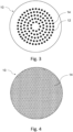
Figure 3 illustrates a schematic front view of a lens element according to an embodiment of the disclosure; -
Figures 4 illustrates schematic front view of a lens element according to an embodiment of the disclosure; and -
Figures 5 illustrates chart-flow of the method for providing a lens element according to an embodiment of the disclosure. - Elements in the figures are illustrated for simplicity and clarity and have not necessarily been drawn to scale. For example, the dimensions of some of the elements in the figure may be exaggerated relative to other elements to help to improve the understanding of the embodiments of the present invention.
- In the reminder of the description, terms like « up », « bottom », « horizontal », « vertical », « above », « below », « front », « rear » or other words indicating relative position may be used. These terms are to be understood in the wearing conditions of the optical lens.
- The disclosure relates to a method for providing a lens element comprising a plurality of diffractive microstructures.
- In the context of the present invention, the term "lens element" can refer to a lens blank or semi-finished lens or an optical lens or a spectacle optical lens edged to fit a specific spectacle frame or an ophthalmic lens, or an optical device adapted to be positioned on an ophthalmic lens, a film, or a wafer.
- As represented in
figure 1 , thelens element 10 is formed by at least afirst lens member 12a and asecond lens member 12b. - The
first lens member 12a may comprise an eye side surface formed as a concave surface and a surface F1 opposed to the eye side surface. Thesecond lens member 12b may comprise an object side surface formed as a convex curved surface toward an object side and a surface F2 opposed to the object side surface. Alternatively, the object side surface and/or the eye side surface may be any one of a plano surface, a convex surface, or a concave surface. The surface F1 of thefirst lens member 12a and the surface F2 of thesecond lens member 12b are complementary surfaces. Both complementary surfaces F1 and F2 are designed to fit precisely into the other to ensure a tight and secure fit when the two lens member are brought together. - At least one complementary surface F1 or F2 comprises a plurality of
diffractive microstructures 14. In the embodiment illustrated infigure 1 , thediffractive microstructures 14 are disposed on surface F1 of thefirst lens member 12a. However, it should be understood that the plurality of diffractive microstructures may be disposed on any complementary surface F1 and/or complementary surface F2. The plurality of diffractive microstructures may be engraved, imprinted, etched, molded, or embossed directly on the surface of a lens member. When the complementary surfaces F1 and F2 are put together, the plurality of diffractive microstructures becomes encapsulated within the lens element. In the sense of the invention, "being encapsulated" should be understood as being surrounded, encased, protected in, or isolated from the outside, as if in a capsule. - The lens element may further comprise at least one additional lens member disposed on any of the first or second lens members. For example, the lens element can comprise a third lens member forming a coating layer disposed on the object side surface of the second lens member. Another lens member may be a support wafer disposed on the eye side surface of the first lens member. The additional lens member may be made of a common material with at least one of the first or second lens members, and thus have the same index of refraction. Alternatively, the additional lens member may be made of a different material from the first and second lens member, and thus have a different index of refraction.
- The first and/or second lens members may be a lens wafer, a film sheet, a layer of glue, a layer of adhesive, a layer of coating element, or a layer of resin.
- In the example illustrated in
figure 2a , thefirst lens member 12a is a lens wafer made of a first material having a first index of refraction n1 and thesecond lens member 12b is lens wafer made of a second material having a second index of refraction n2. The complementary surface F1 of thefirst lens member 12a comprises a plurality ofdiffractive microstructures 14 made of the same first material. - Lens wafers are usually obtained through usual molding processes, for example injection molding or cast molding. In a non-limiting example, the
first lens member 12a is firstly manufactured by injecting the first material into a first master mold, and pressing it against a microstructure pattern of the first master mold. Through hot embossing, the inverse structure of the pattern will be transferred on the surface of thefirst lens member 12a to form the plurality ofdiffractive microstructure 14. The manufacturedfirst lens member 12a is further introduced into a second master mold and the second material is injected and overmolded on the first lens member to form thesecond lens member 12b. - In the example illustrated in
figure 2b , thefirst lens member 12a is a film sheet made of a first material having a first index n1, on which a plurality ofdiffractive microstructures 14 have been imprinted on, for example using usual lithography techniques, or edged on. Thefirst lens member 12a is disposed on an additional third lens member 12c which is a support lens wafer. A layer of glue is further added over the first lens member to maintain it on the support lens wafer. This layer of glue forms thesecond lens member 12b made of a second material having a second index of refraction n2. - In the example illustrated in
figure 2c , thefirst lens member 12a is directly imprinted using a first material having a first index of refraction n1 over the surface of an additional third lens member 12c, for example a support lens wafer. A layer of coating is further applied over thefirst lens member 12a, for example using common techniques such as casting, overmolding or imprinting. The layer of coating forms thesecond lens member 12b made of a second material having a second index of refraction n2. - The first and/or second lens members may be made of any suitable material such as mineral material like glass, or organic material like plastic, resin, epoxy glue, hot melt glue, UV adhesive, pressure sensitive adhesive, rubber. For example, the first and/or the second lens member material may be any of polycarbonate, co-polyester, thermoplastic polyurethane, poly(methyl methacrylate), polyamide, bio-engineered polymers, cellulose triacetate, allyl diglycol carbonate, polyepisulfides, trivex, polyacrylics, polyols, polyamines, polyanhydrides, polycarboxilic acids, polyepoxides, polyisocyanates, polynorbornenes, polysiloxanes, polysilazanes, polystyrenes, polyolefmics, polyesters, polyimides, polyurethanes, polythiourethanes, polyallylics, polysulfides, polyvinylesters, polyvinylethers, polyarylenes, polyoxides, polysulfones, poly cyclo olefins, polyacrylonitriles, polyethylene terephtalates, polyetherimides, polypentenes, acrylate, polyurethane, styrene copolymers, CR39, MR7, MR8, 1.74, 1.56, and the like with the material used for the glue, psa, coating etc.
- The indices of refraction n1 and n2 of the material used for the respective first and second lens members may be suitably selected to obtain targeted optical properties for the lens element. Preferably, the first and second indices of refraction n1 and n2 are different. Preferably, the first and second indices of refraction n1 and n2 is comprised between 1, 3 and 1.7 when measured for a wavelength of 550 nm. For example, the first and second indices of refraction n1 and n2 may be smaller than or equal to, or between any two of, 1.9; 1.8; 1.75; 1.73; 1.71; 1.69; 1.67; 1.65; 1.63; 1.61; 1.59; 1.57; 1.55; 1.54; 1.53; 1.52; 1.51; 1.50; 1.49; 1.48; 1.47; 1.46; 1.45; or lower, and/or greater than or equal to, or between any two of 1.1; 1.2; 1.25; 1.3; 1.31; 1.33; 1.35; 1.37; 1.39; 1.41; 1.43; 1.45; or higher.
- The eye side surface of the first lens member and/or the object side surface of the second lens member may have any suitable shape, such as spherical or non-spherical. The term "spherical shape" refers to the curvature of the lens surface, which closely follows the shape of a perfect or almost perfect sphere. A spherical surface has a substantially uniform curvature over the entire surface of the lens element, which remains substantially the same in all meridians. A non-spherical surface should be understood as not being uniform over the entire surface of the lens element, with different curvatures in different meridians.
- The eye side surface of the first lens member and/or the object side surface of the second lens member may have a toric shape. A toric surface has two principal meridians that are perpendicular to each other, often referred to as the "steep" and "flat" meridians. The curvature of the surface in these meridians is different.
- The eye side surface of the first lens member and/or the object side surface of the second lens member may have an aspherical shape. An aspherical surface has a curvature that progressively vary over the surface of the lens element. The curvature along different meridians varies from the geometrical center of the lens element towards the periphery, for example, the curvature of the surface increases or decreases towards the peripheral part of the surface. The shape of an aspherical surface is typically described using a mathematical equation, such as a conic section or a polynomial equation.
- The eye side surface of the first lens member and/or the object side surface of the second lens member may have progressive addition lens profile. In the sense of the disclosure, a "progressive addition lens profile surface" should be understood as a surface comprising two areas having different spherical surface, and a third areas joining the two first areas, along which the curvature value of the surface transitions from the first the second curvature values of the corresponding two areas.
- Alternatively, the eye side surface of the first lens member and/or the object side surface of the second lens member may have a plano shape. A plano surface has no curvature over the entire surface of the lens element.
- As illustrated in
figure 1 , at least one of thefirst lens member 12a and/or thesecond lens member 12b comprises a plurality of diffractive microstructures. - The plurality of diffractive microstructures are designed to provide an optical function that diffracts or bends light in specific ways. For example, diffractive microstructures can control the phase and amplitude of the diffracted light, thereby modifying the shape of the incident light beam into a single focused point. Alternatively, diffractive microstructures can be used to split a single incident beam of light into multiple beams, redirecting them along different paths, thereby creating a blur or volume of non-focused light.
- As illustrated in
figure 3 , the plurality ofdiffractive microstructures 14 may be a plurality of arrays of lenslets. - Lenslets have a contour shape circumscribed by a circle having a diameter smaller than or equal to 3.0 mm, for example smaller than or equal to 2.5mm, preferably smaller than or equal to 2.0mm, more preferably smaller than or equal to 1.5 mm, for example smaller than or equal to 1.0 mm. The lenslets may further be characterized by their largest inscribed circle that has a diameter greater than or equal to 0.1 mm, preferably greater than or equal to 0.2mm, more preferably greater than or equal to 0.4mm, even more preferably greater than or equal to 0.5mm, for example greater than or equal to 0.6 mm.
- As represented in
figure 3 , at least part, for example more than 50%, preferably all, of thelenslets 14 may be contiguous. - As represented in
figure 4 , at least part, for example more than 50%, preferably all, of thelenslets 14 may be non-contiguous. - In the sense of the disclosure, two lenslets located on a surface of the lens element are contiguous if there is a path supported by said surface that links the two lenslets and if along said path one does not reach the basis surface of the lens element on which the lenslets are superimposed.
- When the surface on which the at least two lenslets are superimposed is spherical, the basis surface corresponds to said spherical surface. In other words, two lenslets superimposed on a spherical surface are contiguous if there is a path supported by said spherical surface and linking them and if along said path one may not reach the spherical surface.
- When the surface on which the at least two lenslets are superimposed is non-spherical, the basis surface corresponds to the local spherical surface that best fits said non-spherical surface. In other words, two lenslets superimposed on a non-spherical surface are contiguous if there is a path supported by said non-spherical surface and linking them and if along said path one may not reach the spherical surface that best fit the non-spherical surface.
- The density of lenslets on the lens element is comprised between 20% and 100%, preferably between 30% and 70%, for example between 40% and 50%. For example, for every circular zone having a radius comprised between 2 and 4 mm comprising a geometrical center located at a distance of the optical center of the lens element greater or equal to said radius + 5mm, the ratio between the sum of areas of the parts of lenslets located inside said circular zone and the area of said circular zone is comprised between 20% and 100%, preferably between 30% and 70%, for example between 40% and 60%.
- As illustrated in
figure 4 , thelenslets 14 may be organized over the entire surface of thelens element 10. In other words, the ratio between the sum of the projected areas of the lens element covered by lenslets and the total is equal to 1. - The lenslets may be positioned on a structured mesh, for example a squared mesh or a hexagonal mesh or a triangle mesh or an octagonal mesh.
- As illustrated in
figure 3 , the lenslets may be organized in a plurality of concentric rings centered on an optical center and/or a geometric center of the surface of the lens member on which the lenslets are disposed. - The radial distance between two successive concentric rings of lenslets may be identical. Alternatively, the radial distance between two successive concentric rings of lenslets, may vary. Preferably, the distance between two successive concentric rings of lenslets is greater than or equal to 1.00 mm, preferably 2.0 mm, more preferably 4.0 mm.
- The
diffractive microstructures 14 may be diffractive lenslets. In the sense of the disclosure, a "diffractive lenslet" is to be understood as a small-scale optical element that acts as a miniature diffractive lens. - The diffractive microstructures may be π-Fresnel lenslets. In the sense of the disclosure π-Fresnel lenslets are Fresnel lenslets whose phase function ψ(r) has π phase jumps at the nominal wavelength λ0, as opposed to unifocal Fresnel lenses whose phase jumps are multiple values of 2n. A π-Fresnel lenslet diffracts light mainly in two diffraction orders (order 0 and +1), for example associated to dioptric powers P(λ0) = 0 δ and a positive one P(λ0) = 3 δ, with λ0 = 550 nm.
- Advantageously, π-Fresnel lenslets allows diffracting incident light towards two different planes, thereby providing two different optical powers.
- As illustrated in
figure 5 , the method for providing a lens element according to the disclosure comprises a step S2 of obtaining first lens member data. - The first lens member data comprises at least data relating to the shape of a first lens member having a surface (F1) comprising diffractive microstructures and to a first refractive index n1 of this first lens member. In the sense of the disclosure, the "shape" of the first lens member should be understood as parameters values and/or equations that allows defining the structure of the first lens member, such as the curvature of the surfaces of the first lens member and/or the thickness of the first lens member.
- As illustrated in
figure 5 , the method for providing a lens element according to the disclosure comprises a step S4 of obtaining second lens member data. - Similarly to the first lens member data, the second lens member data comprises at least data relating to the shape of a second lens member having a surface (F2) complementary to the surface (F1) of the first lens member comprising the plurality of diffractive microstructures and to a second refractive index n2 of this second lens member. In the sense of the disclosure, the "shape" of the second lens member should be understood as parameters values and/or equations that allows defining the structure of the second lens member, such as the curvature of the surfaces of the second lens member and/or the thickness of the second lens member.
- As illustrated in
figure 5 , the method for providing a lens element according to the disclosure further comprises a step S6 of generating a lens element model. - In the sense of the disclosure, a "lens element model" is a simulation or simplified representation or mathematical description of the behavior and characteristics of a lens element. The lens element model is a theoretical framework allowing for the analysis and prediction of how light interacts with the lens element and how the lens affects the propagation of light. Typically, optical lens models are based on several fundamental principles of optics, including geometric optics and wave optics.
- Advantageously, the lens element model accurately simulates the optical properties of the lens element.
- The lens element model is generated based on the first lens member data and the second lens member data. Using the data relating to the shape and index of refraction of the lens members, a lens element model is generated by simulating both lens members and applying their complementary surfaces (F1) and (F2) together.
- As illustrated in
figure 5 , the method for providing a lens element according to the disclosure further comprises a step S8 of obtaining energy balance data. - The energy balance data comprises at least data relating to at least two maximum levels of modulation transfer function (MTF) of the lens element model in at least two distinct planes (z1, z2).
- The modulation transfer function (MTF) is a well-known quantitative measurement that describes the imaging performance of an optical system. The MTF characterizes an optical system's ability to reproduce fine details and resolve spatial frequencies. It measures the contrast transfer as a function of the spatial frequency of the object being imaged and provides information about the optical system's resolving power and the amount of contrast degradation for different spatial frequencies.
- Typically, a high MTF value indicates that the optical system can effectively reproduce high-frequency details with minimal contrast loss, resulting in a sharp and detailed image. Conversely, a low MTF value indicates a reduction in contrast and loss of fine details as the spatial frequency increases.
- The modulation transfer function may be determined by measuring the 3D surface of the lens element, determining a 2D representation of optical path differences of a light beam arriving normal to the lens element, determining the point spread function over a pupil aperture, for example having a diameter comprised between 2mm and 8mm, preferably between 3mm and 6mm, for example 4mm, and centered at 6.6 mm from the optical center of the lens element, and determining the modulation transfer function over said pupil by a Fourier transform operation.
- Advantageously, the utilization of a lens model provides a efficient and facilitated way to determine the MTF profile of a lens element without requiring the involvement of a wearer or a eye-lens optical system.
- The energy balance data represents predefined or targeted position of two planes (z1, z2) in which the clearest images of an object passing through the lens element is obtained, i.e., the two planes for which maximum values of MTF can be obtained. The two planes (z1, z2) are parallel with the normal plane tangent with the optical and/or geometrical center of the lens element.
- When the diffractive microstructures are π-Fresnel lenslets, the at least two maximum levels of MTF measured in the planes z1 and z2 respectively corresponds to the first order of diffraction 0 and the second order of diffraction +1 of the π-Fresnel lenslets.
- As illustrated in
figure 5 , the method for providing a lens element according to the disclosure further comprises a step S10 of optimizing the lens element model. The lens element model is optimized based on the energy balance data. - During the optimization step, the lens element model are optimized by modifying, refining, and improving the first and second lens members data. Typically, parameters values and/or equations defining the structure of the first and/or second lens members are modified to obtain targeted optical properties.
- Preferably, at least one of the first and second refractive index n1 and n2 of the first and/or second lens member is varied so that over at least one pupil englobing at least part of the plurality of diffractive microstructures of the lens member, the at least two targeted maximum levels of MTF defined by the energy balance data can be measured in the at least two distinct planes (z1, z2).
- Advantageously, optimizing the index of refraction of at least one lens member allows easily tuning the optical function of the lens member while conserving the initial surface design of the lens element. Indeed, it has been observed by the inventors that modifying the combination of indices of refraction of the two lens members allows obtaining a wild range of diffractive profiles for the lens member.
- As illustrated in
figure 5 , the method for providing a lens element according to the disclosure further comprises a step S12 of providing the lens element. - The lens element is obtained by manufacturing and assembling the first and second lens members based on the optimized lens element model. Alternatively, the first and/or second lens members may be selected from a bank of premade lens members. The first and second lens members are assembled so that the diffractive microstructures are encapsulated between said first and second lens members.
- As illustrated in
figure 5 , the method for providing a lens element according to the disclosure may further comprise a step S14 of providing prescription data. The prescription data relates at least to a prescription adapted for a wearer. - The term "prescription" is to be understood to mean a set of optical characteristics of optical power, of astigmatism, of prismatic deviation, determined by an ophthalmologist or optometrist in order to correct the vision defects of the eye, for example by means of a lens positioned in front of his eye. For example, the prescription for a myopic eye comprises the values of optical power and of astigmatism with an axis for the distance vision. The prescription may comprise an indication that the eye of the wearer has no defect and that no refractive power is to be provided to the wearer.
- The prescription in ophthalmic field may comprise, in addition to the power prescription, an astigmatism prescription. Such a prescription is composed of an axis value (in degrees) and a module value (in diopters). The module value represents the difference between the maximal and minimal power in a given direction allowing to correct the visual default of a wearer. Following the convention, the axis represents the orientation of one of the two powers versus a reference axis and following a given rotation direction. TABO convention may be used. In this convention the reference axis is horizontal and the rotation direction is counterclockwise when looking at the wearer. A 45° axis corresponds to an axis orientated obliquely linking, when looking at the wearer, the upper right quadrant to the lower left quadrant. Such an astigmatism prescription is measured for the wearer in far vision. The term 'astigmatism' is used to refer to the couple (module, axis). That term is sometimes used to simply designate the module. The skilled person easily understands what it refers to depending on the context. The skilled person is also aware that the power/astigmatism prescription for a wearer is commonly described with the terms sphere, cylinder and axis.
- The wearing conditions are to be understood as the position of the lens element with relation to the eye of a wearer, for example defined by a pantoscopic angle, a wrap angle, a Cornea to lens distance, and eventually any of a Pupil-cornea distance, a center of rotation of the eye (ERC) to pupil distance, an ERC to lens distance.
- The Cornea to lens distance is the distance along the visual axis of the eye in the primary position (usually taken to be the horizontal) between the cornea and the back surface of the lens; for example comprised between 6 and 20, for example 8 and 16 mm, preferably 10 and 14 mm, more preferably equal to 12mm.
- The Pupil-cornea distance is the distance along the visual axis of the eye between its pupil and cornea; usually comprised between 1 and 4 mm, for example equal to 2mm.
- The ERC to pupil distance is the distance along the visual axis of the eye between its center of rotation (ERC) and cornea; for example comprised between 10 and 15 mm, preferably 11 and 12 mm, more preferably equal to 11.5mm.
- The ERC to lens Q'O distance is the distance along the visual axis of the eye in the primary position (usually taken to be the horizontal) between the ERC of the eye and the back surface of the lens, for example comprised between 20 and 30 mm, preferably 22.5 and 28 mm, more preferably equal to 25.5mm.
- The pantoscopic angle is the angle in the vertical plane, at the intersection between the back surface of the lens and the visual axis of the eye in the primary position (usually taken to be the horizontal), between the normal to the back surface of the lens and the visual axis of the eye in the primary position; for example comprised between -25° and +5°, preferably -12° and 0°, more preferably between -10° and -6°, for example equal to -8° or 0°, .
- The wrap angle is the angle in the horizontal plane, at the intersection between the back surface of the lens and the visual axis of the eye in the primary position (usually taken to be the horizontal), between the normal to the back surface of the lens and the visual axis of the eye in the primary position for example comprised between -10° and +25°, preferably 0° and 10°, more preferably between 0° and +5°, for example equal to 0°.
- An example of standard wearing condition may be defined by a pantoscopic angle of - 8°, a Cornea to lens distance of 12 mm, a Pupil-cornea distance of 2 mm, an ERC to pupil distance of 11.5 mm, an ERC to lens distance of 25.5 mm and a wrap angle of 0°.
- Another example of standard wearing condition more adapted for younger wearers may be defined by a pantoscopic angle of 0°, a Cornea to lens distance of 12 mm, a Pupil-cornea distance of 2 mm, an ERC to pupil distance of 11.5 mm, a ERC to lens distance of 25.5 mm and a wrap angle of 0°.
- Advantageously, the prescription of a person provides sufficient information to determine the position of the retina of the eye of the person.
- As illustrated in
figure 5 , the method for providing a lens element according to the disclosure may further comprise a step S16 of manufacturing an ophthalmic lens. The lens element is manufactured based on the prescription data to obtain an ophthalmic lens adapted to the wearer. - Typically, at least one of the eye side surfaces of the first lens member and/or the object side surface of the second lens member forming the lens element is processed, for example grinded and edged, to modify the design of the lens element. Furthermore, a layer of coating element may be applied over at least one part, preferably all, of a surface of the lens element. The at least one layer of coating element may comprise features selected from the group consisting of anti-scratch, anti-reflection, anti-smudge, anti-dust, UV30 filtration, blue light-filtration, anti-abrasion features.
- Advantageously, having the diffractive microstructures encapsulated between the first and second lens members allows simplifying the manufacturing step.
- During the step of manufacturing the ophthalmic lens, at least one surface of the lens member may be modified to have the plane z1, in which a maximum level of MTF can be measured over a predefined pupil, coincides with the plane of the retina of the wearer for which the lens is adapted to. In other words, at least one surface is manufactured so that when the wearer is wearing the ophthalmic lens in standard wearing conditions and looks straight ahead at an object located at infinity, light from the object passing through the diffractive microstructures and the eye will form a clear image on its retina.
- Advantageously, it allows providing an ophthalmic lens improving the visual acuity of the wearer.
- During the step of manufacturing the ophthalmic lens, at least one surface of the lens member may be modified to have the plane z2, in which a maximum level of MTF can be measured over a predefined pupil, is located in front or behind the plane of the retina of the wearer for which the lens is adapted to. In other words, at least one surface is manufactured to have the ophthalmic lens providing a blurred image or a defocus to the wearer wearing the ophthalmic lens in standard wearing conditions.
- Advantageously, providing a blurred image or a defocus in front or behind the retina allows creating a stop signal that slows down the progression of an abnormal refraction of the eye of the wearer.
- The disclosure further relates to a computer program product comprising one or more stored sequences of instructions that are accessible to a processor and which, when executed by the processor, causes the processor to carry out the steps of a method according to the disclosure.
- The disclosure further relates to a computer readable medium carrying one or more sequences of instructions of the computer program product according to the disclosure.
- Furthermore, the disclosure relates to a program which makes a computer execute a method of the disclosure.
- The disclosure also relates to a computer-readable storage medium having a program recorded thereon; where the program makes the computer execute a method of the disclosure.
- The disclosure further relates to a device comprising a processor adapted to store one or more sequence of instructions and to carry out at least one of the steps of a method according to the disclosure.
- The disclosure further relates to a non-transitory program storage device, readable by a computer, tangibly embodying a program of instructions executable by the computer to perform a method of the present disclosure.
- Unless specifically stated otherwise, as apparent from the following discussions, it is appreciated that throughout the specification discussions utilizing terms such as "computing", "calculating", "generating", or the like, refer to the action and/or processes of a computer or computing system, or similar electronic computing device, that manipulate and/or transform data represented as physical, such as electronic, quantities within the computing system's registers and/or memories into other data similarly represented as physical quantities within the computing system's memories, registers or other such information storage, transmission or display devices.
- Embodiments of the present invention may include apparatuses for performing the operations herein. This apparatus may be specially constructed for the desired purposes, or it may comprise a general purpose computer or Digital Signal Processor ("DSP") selectively activated or reconfigured by a computer program stored in the computer. Such a computer program may be stored in a computer readable storage medium, such as, but is not limited to, any type of disk including floppy disks, optical disks, CD-ROMs, magnetic-optical disks, read-only memories (ROMs), random access memories (RAMs) electrically programmable read-only memories (EPROMs), electrically erasable and programmable read only memories (EEPROMs), magnetic or optical cards, or any other type of media suitable for storing electronic instructions, and capable of being coupled to a computer system bus.
- The processes and displays presented herein are not inherently related to any particular computer or other apparatus. Various general purpose systems may be used with programs in accordance with the teachings herein, or it may prove convenient to construct a more specialized apparatus to perform the desired method. The desired structure for a variety of these systems will appear from the description below. In addition, embodiments of the present invention are not described with reference to any particular programming language. It will be appreciated that a variety of programming languages may be used to implement the teachings of the inventions as described herein.
- Many further modifications and variations will be apparent to those skilled in the art upon making reference to the foregoing illustrative embodiments, which are given by way of example only and which are not intended to limit the scope of the disclosure, that being determined solely by the appended claims.
- In the claims, the word "comprising" does not exclude other elements or steps, and the indefinite article "a" or "an" does not exclude a plurality. The mere fact that different features are recited in mutually different dependent claims does not indicate that a combination of these features cannot be advantageously used. Any reference signs in the claims should not be construed as limiting the scope of the disclosure.
Claims (15)
- A method for providing a lens element, the lens element comprising a plurality of encapsulated diffractive microstructures, the method comprising:(S2) obtaining first lens member data, the first lens member data comprising at least data relating to a shape of a first lens member and to a first refractive index n1 of the first lens member, at least one surface (F1) of the first lens member comprising a plurality of diffractive microstructures;(S4) obtaining second lens member data, the second lens member data comprising at least data relating to a shape of a second lens member and to a second refractive index n2 of the second lens member, the second lens member comprising at least one surface (F2) complementary to the surface of the first lens member comprising the plurality of diffractive microstructures;(S6) generating a lens element model based on the first and second lens member data, the lens element model being formed by applying the complementary surfaces of the first and second lens member together,(S8) obtaining energy balance data, the energy balance data comprising at least data relating to at least two maximum levels of MTF in at least two distinct planes (z1, z2);(S10) optimizing the lens element model based on the energy balance data, the lens member being optimized by varying at least one of the first and second refractive index n1 and n2 of the first and second lens member so that over at least one pupil englobing at least part of the plurality of diffractive microstructures of the lens member, the at least two maximum levels of MTF can be measured in the at least two distinct planes (z1, z2);(S12) providing the lens element by assembling at least the first and second lens members based on the optimized lens element model.
- The method according to claim 1 further comprising a step (S14) of providing prescription data, the prescription data relating at least to a prescription adapted for a wearer; and a step (S16) of manufacturing an ophthalmic lens from the lens element based on the prescription data.
- The method according to claim 2, wherein during the step of manufacturing the ophthalmic lens, at least one surface of the lens element is modified so that the first plane z1 in which a maximum level of MTF can be measured over the pupil coincides with the plane of the retina of the wearer.
- The method according to any of claims 2 or 3, wherein during the step of manufacturing the ophthalmic lens, at least one surface of the lens element is modified so that the second plane z2 in which a maximum level of MTF can be measured over the pupil is located in front or behind the plane of the retina of the wearer.
- The method according to any of the preceding claims, wherein at least part of the plurality of diffractive microstructures are arrays of lenslets.
- The method according to claim 5, wherein the lenslets are organized over the entire surface of the lens element.
- The method according to any of claims 5 to 6, wherein at least part, for example all, of the lenslets are non-contiguous.
- The method according to any of claims 5 to 6, wherein at least part, for example all, of the lenslets are contiguous.
- The method according to any of claims 5 to 8, wherein the lenslets have a contour shape circumscribed by a circle having a diameter smaller than or equal to 3.0 mm, for example smaller than or equal to 1.5 mm, for example smaller than or equal to 1.0 mm, and the largest inscribed circle has a diameter greater than or equal to 0.1 mm, for example greater than or equal to 0.6 mm.
- The method according to any of claims 5 to 9, wherein the lenslets are organized in concentric rings.
- The method according to any of claims 1 to 10, wherein at least part of the plurality of diffractive microstructures are diffractive lenslets.
- The method according to claim 11, wherein at least part, preferably all, of the diffractive lenslets are π-Fresnel lenslets.
- The method according to claim 12, wherein the at least two maximum levels of MTF measured in the planes z1 and z2 correspond to the first order of diffraction and the second order of diffraction of the π-Fresnel lenslets.
- The method according to any of claims 1 to 13, wherein at least one of the first or second lens member is a wafer, a film sheet, an adhesive layer, or a coating layer.
- A lens element comprising a plurality of encapsulated diffractive microstructures obtained using the method according to any of claims 1 to 14.
Priority Applications (4)
| Application Number | Priority Date | Filing Date | Title |
|---|---|---|---|
| EP23306508.5A EP4521159A1 (en) | 2023-09-11 | 2023-09-11 | Method for providing a lens element |
| CN202480057654.XA CN121816531A (en) | 2023-09-11 | 2024-08-29 | Method for providing a lens element |
| KR1020267002687A KR20260053281A (en) | 2023-09-11 | 2024-08-29 | Method of providing lens elements |
| PCT/EP2024/074231 WO2025056336A1 (en) | 2023-09-11 | 2024-08-29 | Method for providing a lens element |
Applications Claiming Priority (1)
| Application Number | Priority Date | Filing Date | Title |
|---|---|---|---|
| EP23306508.5A EP4521159A1 (en) | 2023-09-11 | 2023-09-11 | Method for providing a lens element |
Publications (1)
| Publication Number | Publication Date |
|---|---|
| EP4521159A1 true EP4521159A1 (en) | 2025-03-12 |
Family
ID=88241138
Family Applications (1)
| Application Number | Title | Priority Date | Filing Date |
|---|---|---|---|
| EP23306508.5A Pending EP4521159A1 (en) | 2023-09-11 | 2023-09-11 | Method for providing a lens element |
Country Status (4)
| Country | Link |
|---|---|
| EP (1) | EP4521159A1 (en) |
| KR (1) | KR20260053281A (en) |
| CN (1) | CN121816531A (en) |
| WO (1) | WO2025056336A1 (en) |
Families Citing this family (1)
| Publication number | Priority date | Publication date | Assignee | Title |
|---|---|---|---|---|
| US20250291100A1 (en) * | 2024-03-18 | 2025-09-18 | Google Llc | Optical material encapsulated diffractive gratings |
Citations (9)
| Publication number | Priority date | Publication date | Assignee | Title |
|---|---|---|---|---|
| US20130100403A1 (en) * | 2011-10-19 | 2013-04-25 | Michael J. Simpson | Determining physical lengths in an eye using multiple refractive indices |
| WO2017192333A1 (en) * | 2016-05-05 | 2017-11-09 | Pillar Bioscience Llc | Intraocular lens and associated design and modeling methods |
| WO2018152595A1 (en) * | 2017-02-27 | 2018-08-30 | Brien Holden Vision Institute | Ophthalmic lens system for controlling and/or reversing the longitudinal chromatic aberration of a human eye using a diffractive optical element |
| US20210354410A1 (en) * | 2018-10-17 | 2021-11-18 | Essilor International | Optical Articles Comprising Encapsulated Microlenses and Methods of Making the Same |
| US20220244542A1 (en) * | 2019-06-21 | 2022-08-04 | Essilor International | Set of semi-finished lenses with holographic components |
| WO2022254389A1 (en) * | 2021-06-03 | 2022-12-08 | Brien Holden Vision Institute Limited | Ophthalmic lenses utilizing binary amplitude modulation |
| US20230034749A1 (en) * | 2016-10-25 | 2023-02-02 | Brien Holden Vision Institute Limited | Devices, Systems and/or Methods for Myopia Control |
| US20230200975A1 (en) * | 2019-04-05 | 2023-06-29 | Amo Groningen B.V. | Systems and methods for correcting photic phenomenon from an intraocular lens and using refractive index writing |
| US20230221579A1 (en) * | 2020-05-28 | 2023-07-13 | Sifi S.P.A. | Ophthalmic lens |
-
2023
- 2023-09-11 EP EP23306508.5A patent/EP4521159A1/en active Pending
-
2024
- 2024-08-29 WO PCT/EP2024/074231 patent/WO2025056336A1/en not_active Ceased
- 2024-08-29 CN CN202480057654.XA patent/CN121816531A/en active Pending
- 2024-08-29 KR KR1020267002687A patent/KR20260053281A/en active Pending
Patent Citations (9)
| Publication number | Priority date | Publication date | Assignee | Title |
|---|---|---|---|---|
| US20130100403A1 (en) * | 2011-10-19 | 2013-04-25 | Michael J. Simpson | Determining physical lengths in an eye using multiple refractive indices |
| WO2017192333A1 (en) * | 2016-05-05 | 2017-11-09 | Pillar Bioscience Llc | Intraocular lens and associated design and modeling methods |
| US20230034749A1 (en) * | 2016-10-25 | 2023-02-02 | Brien Holden Vision Institute Limited | Devices, Systems and/or Methods for Myopia Control |
| WO2018152595A1 (en) * | 2017-02-27 | 2018-08-30 | Brien Holden Vision Institute | Ophthalmic lens system for controlling and/or reversing the longitudinal chromatic aberration of a human eye using a diffractive optical element |
| US20210354410A1 (en) * | 2018-10-17 | 2021-11-18 | Essilor International | Optical Articles Comprising Encapsulated Microlenses and Methods of Making the Same |
| US20230200975A1 (en) * | 2019-04-05 | 2023-06-29 | Amo Groningen B.V. | Systems and methods for correcting photic phenomenon from an intraocular lens and using refractive index writing |
| US20220244542A1 (en) * | 2019-06-21 | 2022-08-04 | Essilor International | Set of semi-finished lenses with holographic components |
| US20230221579A1 (en) * | 2020-05-28 | 2023-07-13 | Sifi S.P.A. | Ophthalmic lens |
| WO2022254389A1 (en) * | 2021-06-03 | 2022-12-08 | Brien Holden Vision Institute Limited | Ophthalmic lenses utilizing binary amplitude modulation |
Also Published As
| Publication number | Publication date |
|---|---|
| WO2025056336A1 (en) | 2025-03-20 |
| CN121816531A (en) | 2026-04-07 |
| KR20260053281A (en) | 2026-04-21 |
Similar Documents
| Publication | Publication Date | Title |
|---|---|---|
| EP3867672B1 (en) | Improved optical article incorporating optical elements and manufacturing method thereof | |
| CN111615660B (en) | Optical lens | |
| KR102908860B1 (en) | optical system | |
| CN101467076B (en) | Disk for modification of the focal power of an optical component | |
| CN113196145B (en) | Methods and apparatus for manufacturing ophthalmic lenses | |
| JP2000056275A (en) | Progressive additional lens | |
| CN117742005B (en) | A spectacle lens with microstructure and design method thereof | |
| JP2011507011A (en) | Curved disk for correcting power in optical components | |
| CN118284840A (en) | Optical lens element for slowing down the progression of visual refractive error | |
| CN118409441A (en) | Lens and glasses | |
| CN221446418U (en) | Spectacle lens and spectacles | |
| WO2025056336A1 (en) | Method for providing a lens element | |
| CN217718323U (en) | Spectacle lens and spectacles | |
| EP4684245A1 (en) | Lens element with optimized microlenses for abnormal refraction control | |
| EP4101626A1 (en) | Method for obtaining a lens element | |
| US20260098987A1 (en) | Manufacturing method of an optical article incorporating optical elements by inkjet printing | |
| US20250144899A1 (en) | Method for manufacturing a spectacle lens | |
| WO2025104155A1 (en) | Anticipation of the change in lens physical dimensions and functionality during its manufacturing process | |
| KR20230153354A (en) | Glasses lenses and their design methods | |
| CN120858309A (en) | Myopia control device for primary correction | |
| WO2025133136A1 (en) | Chromatic optimizartion of phase-shift designs for myopia control |
Legal Events
| Date | Code | Title | Description |
|---|---|---|---|
| PUAI | Public reference made under article 153(3) epc to a published international application that has entered the european phase |
Free format text: ORIGINAL CODE: 0009012 |
|
| STAA | Information on the status of an ep patent application or granted ep patent |
Free format text: STATUS: THE APPLICATION HAS BEEN PUBLISHED |
|
| AK | Designated contracting states |
Kind code of ref document: A1 Designated state(s): AL AT BE BG CH CY CZ DE DK EE ES FI FR GB GR HR HU IE IS IT LI LT LU LV MC ME MK MT NL NO PL PT RO RS SE SI SK SM TR |
|
| STAA | Information on the status of an ep patent application or granted ep patent |
Free format text: STATUS: REQUEST FOR EXAMINATION WAS MADE |
|
| 17P | Request for examination filed |
Effective date: 20250408 |
|
| GRAP | Despatch of communication of intention to grant a patent |
Free format text: ORIGINAL CODE: EPIDOSNIGR1 |
|
| STAA | Information on the status of an ep patent application or granted ep patent |
Free format text: STATUS: GRANT OF PATENT IS INTENDED |
|
| INTG | Intention to grant announced |
Effective date: 20260507 |