EP4521143A1 - System for detecting gamma rays or x-rays with improved collimation - Google Patents
System for detecting gamma rays or x-rays with improved collimation Download PDFInfo
- Publication number
- EP4521143A1 EP4521143A1 EP23306507.7A EP23306507A EP4521143A1 EP 4521143 A1 EP4521143 A1 EP 4521143A1 EP 23306507 A EP23306507 A EP 23306507A EP 4521143 A1 EP4521143 A1 EP 4521143A1
- Authority
- EP
- European Patent Office
- Prior art keywords
- rays
- detector
- lim
- gamma rays
- angle
- Prior art date
- Legal status (The legal status is an assumption and is not a legal conclusion. Google has not performed a legal analysis and makes no representation as to the accuracy of the status listed.)
- Withdrawn
Links
Images
Classifications
-
- G—PHYSICS
- G01—MEASURING; TESTING
- G01T—MEASUREMENT OF NUCLEAR OR X-RADIATION
- G01T1/00—Measuring X-radiation, gamma radiation, corpuscular radiation, or cosmic radiation
- G01T1/29—Measurement performed on radiation beams, e.g. position or section of the beam; Measurement of spatial distribution of radiation
-
- G—PHYSICS
- G01—MEASURING; TESTING
- G01T—MEASUREMENT OF NUCLEAR OR X-RADIATION
- G01T1/00—Measuring X-radiation, gamma radiation, corpuscular radiation, or cosmic radiation
- G01T1/29—Measurement performed on radiation beams, e.g. position or section of the beam; Measurement of spatial distribution of radiation
- G01T1/2914—Measurement of spatial distribution of radiation
- G01T1/2985—In depth localisation, e.g. using positron emitters; Tomographic imaging (longitudinal and transverse section imaging; apparatus for radiation diagnosis sequentially in different planes, steroscopic radiation diagnosis)
Definitions
- the invention relates to the detection of gamma rays or X-rays. More precisely, the invention relates to a system for detecting gamma rays or X-rays and to a method for detecting gamma rays or X-rays involving the use of such a system.
- gamma cameras commonly utilize a heavy lead collimator, a planar scintillation crystal, and a coarse array of bulky photomultiplier tubes.
- the collimator absorbs all incident gamma photons except those traveling in a specific direction at each cell in the collimator in order to reconstruct a meaningful planar image of an object located in a specific direction with respect to the camera.
- Collimators with different acceptance geometries are available but must be physically exchanged with a cumbersome transport mechanism capable of supporting their substantial weight.
- a collimator drastically reduces the counting efficiency of the gamma camera. It adds great weight to the camera detector heads which, in turn, must be supported by a very heavy gantry. Exchanging collimators requires time and labor, thereby reducing patient throughput. The bulky exchange mechanism occupies a sizeable space and is subject to mechanical misalignment, thereby requiring service calls.
- the document WO0188493A1 discloses a Compton deconvolution camera aiming to solve the aforementioned burdens by providing a system comprising a pair of detectors and a control unit configured to construct an image of an object based on data provided by the detectors. A collimation is performed by the means of the combination of the two detectors, thus allowing to remove the need of a collimator as mentioned above.
- the Compton deconvolution camera comes with new issues. Indeed, the construction of the image of the object is based on a deconvolution operation using the distribution of Compton scattered photons detected by the detectors. This deconvolution operation induces a heavy load on the control unit, meaning the control unit must be powerful enough to process this operation, which raises the cost of the system. In addition, the deconvolution operation may take some long time to process, such that the image is only rendered after a lap of time, which is inconvenient.
- a method for detecting gamma rays or X-rays involving the use of a system for measuring gamma rays or X-rays comprising:
- the configuration of the system for detecting gamma rays or X-rays allows to have a double collimation along the main axis without needing a physical collimator.
- a geometrical collimation is obtained by the geometrical configuration of the first and second detectors, determined by the parameters formed by the width W and the distance D.
- An electronical collimation is obtained by the thresholding of the energy E 1 .
- an event as defined above results from a Compton scattering occurring at the first detecting surface, the angle of the Compton scattering being an increasing function of the energy E 1 deposited in the first detector.
- thresholding the energy E 1 is equivalent to thresholding the angle of the Compton scattering occurring at the first detecting surface considered by the control unit.
- the collimation of the system is thus obtained without the use of a bulky collimator similar to the one of the prior art previously discussed, making the system compact, lightweight and easy to manipulate.
- the electronical collimation is realized with thresholding operations without the need of generating a Compton deconvolution image of the object in front of the system. It is thus understood that the invention needs far less calculations and mathematical operations from the control unit compared to the prior art document presented above. In other words, the invention puts less pressure on the control unit compared to the prior art document presented above, making it simpler to implement.
- the electronical collimation can be accurately configured to only detect gamma rays or X-rays not departing to much from the main axis of the system.
- the limit energy E lim is determined so that ⁇ lim is lower than 30°, preferably lower than 10°.
- the geometrical collimation can be accurately configured to only detect gamma rays or X-rays not departing to much from the main axis of the system.
- the width W and the distance D are determined so that the max angle ⁇ max is lower than 20°, preferably lower than 10°.
- the global collimation of the system can be accurately configured to only detect gamma rays or X-rays not departing to much from the main axis of the system.
- a system for detecting gamma rays or X-rays comprising:
- the system further comprises a collimation device wrapping at least the first and second detectors and having a collimation direction parallel to the main axis of the system.
- the collimation device provides an optional third level of collimation, allowing an even more precise collimation of the system. Moreover, the collimation device serves as a housing for the system, making it easier to handle and manipulate the system.
- the collimation device has the shape of a tube.
- the collimation device is thus easy to conceive.
- the collimation device has a width which is less than 10 mm.
- the collimation device is thus much less bulky than the collimation device of the prior art.
- the system is a portable system weighing less than 1 kg, preferably less than 500 g.
- the system is thus easy to handle, which allows it to be easily used by a human operator and moved around a source of gamma rays or X-rays.
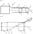
- Figure 1 represents a system for detecting gamma rays or X-rays 2 according to an embodiment of the invention.
- the system 2 comprises a first monolithic non-pixelated detector 4 and a second monolithic non-pixelated detector 6 which are configured for detecting gamma rays or X-rays.
- the first and second detectors 4, 6 are aligned along a main axis 8 of the system 2.
- the first detector 4 has a first detecting surface 10 oriented perpendicularly to the main axis 8 and the second detector has a second detecting surface 12 also oriented perpendicularly to the main axis 8, the second detector 8 being positioned behind the first detector 6 considering the direction of rays entering the system 2 from the first detecting surface.
- the system 2 comprises a control unit 14 connected to the first and second detectors 4, 6.
- the connection is realized by the means of conductive wires 16, but according to a variant of the embodiment, the control unit 14 is connected to the first and second detectors 4, 6 by the means of a wireless protocol such that the conductive wires are not needed.
- the operation of the control unit 14 will be described at a later stage.
- the system 2 comprises a collimation device 18 wrapping at least the first and second detectors 4, 6 and having a collimation direction parallel to the main axis 8 of the system 2.
- the collimation device 18 has the shape of a cylinder which generatrix is parallel to the main axis 8. In this particular embodiment, the collimation device has the general shape of a tube having a width which is less than 10 mm, here equal to 3.5 mm.
- the collimation device 18 is made of a material having a high gamma ray or X-ray absorption coefficient, for example tungsten, lead, molybdenum or a combination thereof. The function of the collimation device 18 will be described at a later stage.
- the system 2 is a portable system in a sense that it can be easily used by a human operator and moved around a source of gamma rays or X-rays.
- the system 2 can be compared to a flashlight which can be easily manipulated with one hand. To this end, the system 2 weighs less than 1 kg, preferably less than 500 g.
- Figure 2 shows the geometrical configuration of the first and second detectors 4, 6 within the system 2.
- the first and second detectors 4, 6 have a same width W and are spaced by a distance D defined by the distance separating the first detecting surface 10 from the second detecting surface 12 along the main axis 8.
- the width W and the distance D are determined so that the max angle ⁇ max is lower than 20°, preferably lower than 10°.
- the value of the max angle ⁇ max can be lowered by increasing the value of the distance D, i.e. by further distancing the first detector 4 from the second detector 6.
- the system 2 may be used to carry out a method for detecting gamma rays or X-rays which will now be described.
- An example of application of the invention is the detection of gamma rays or X-rays in medical surgery for the detection and ablation of tissues marked by a radioactive element, in which it is needed to detect the radiation in a specific direction, for which a collimation must be involved.
- an “event” refers to the detection of an ionizing particle in the first detector in coincidence with the detection of a particle in the second detector within a time frame of 2 ns.
- the limit energy E lim is determined so that the limit angle ⁇ lim is lower than 30°, preferably lower than 10°.
- the gamma ray or X-ray must pass through both the first and second detectors 4, 6. Therefore, the incident ray must have an incident angle with respect to the main axis 8 of the system 2 which is lower than or equal to ⁇ max , previously introduced, when propagating from the first detecting surface 10 to the second detecting surface 12.
- the limit energy E lim , the width W and the distance D are determined so that the collimation angle ⁇ coll is lower than 40°, preferably lower than 20°.
- the collimation obtained by the system 2 is thus a combination of a geometrical collimation, obtained by the geometrical configuration of the first and second detectors 4,6, and an electronical collimation, obtained by the thresholding of the energy E 1 deposited in the first detector 4.
- the limit energy E lim , the width W and the distance D are parameters of the system 2 which allows to calibrate the collimation, i.e. the collimation angle ⁇ coll , obtained by the system 2.
- the system 2 is therefore calibrated to detect the gamma rays or X-rays coming from a source or object close to the main axis 8 of the system 2. It is understood that such sources can be selected by choosing the orientation of the main axis 8, i.e., by choosing the orientation of the system 2.
- the collimation device 18 allows for a third level of collimation by blocking the gamma rays or X-rays coming from directions having an incident angle greater than the collimation angle ⁇ coll , or even greater than the max angle ⁇ max , so as to prevent the control unit 14 from processing useless data.
- the first monolithic non-pixelated detector may be replaced by a semi conductor. More generally, both the first and second detectors can be formed by either a direct conversion type of detector, i.e. semi conductor, or an indirect conversion type of detector, i.e. scintillators or plastics, pixelized or not.
Landscapes
- Physics & Mathematics (AREA)
- Health & Medical Sciences (AREA)
- Life Sciences & Earth Sciences (AREA)
- General Physics & Mathematics (AREA)
- High Energy & Nuclear Physics (AREA)
- Molecular Biology (AREA)
- Spectroscopy & Molecular Physics (AREA)
- Measurement Of Radiation (AREA)
Abstract
This method for detecting gamma rays or X-rays involves the use of a system for measuring gamma rays or X-rays (2) comprising:
- a first detector (4),
- a second detector (6) positioned behind the first detector (4), and
- a control unit (14) connected to the first and second detectors (4, 6) and configured to select events consisting of the detection of an ionizing particle in the first detector in coincidence with the detection of a particle in the second detector within 2 ns, the method comprising the step consisting of determining if an energy E1 deposited by the ionizing particle in the first detector (4) is lower than the threshold energy value, or limit energy, Elim.
- a first detector (4),
- a second detector (6) positioned behind the first detector (4), and
- a control unit (14) connected to the first and second detectors (4, 6) and configured to select events consisting of the detection of an ionizing particle in the first detector in coincidence with the detection of a particle in the second detector within 2 ns, the method comprising the step consisting of determining if an energy E1 deposited by the ionizing particle in the first detector (4) is lower than the threshold energy value, or limit energy, Elim.
Description
- The invention relates to the detection of gamma rays or X-rays. More precisely, the invention relates to a system for detecting gamma rays or X-rays and to a method for detecting gamma rays or X-rays involving the use of such a system.
- In nuclear medicine, it is known to acquire data, like images, of internal structures or functions of a patient's body by using one or more gamma camera or X-ray camera detector heads to detect radiation emitted by a radiopharmaceutical that has been injected into the patient's body. A control unit controls the camera detector heads to acquire data and then processes the acquired data to generate images.
- Existing gamma cameras commonly utilize a heavy lead collimator, a planar scintillation crystal, and a coarse array of bulky photomultiplier tubes. The collimator absorbs all incident gamma photons except those traveling in a specific direction at each cell in the collimator in order to reconstruct a meaningful planar image of an object located in a specific direction with respect to the camera. Collimators with different acceptance geometries are available but must be physically exchanged with a cumbersome transport mechanism capable of supporting their substantial weight.
- A collimator drastically reduces the counting efficiency of the gamma camera. It adds great weight to the camera detector heads which, in turn, must be supported by a very heavy gantry. Exchanging collimators requires time and labor, thereby reducing patient throughput. The bulky exchange mechanism occupies a sizeable space and is subject to mechanical misalignment, thereby requiring service calls.
- The document
WO0188493A1 - In the view of above, there exists a need for a system for detecting gamma rays or X-rays coming from a specific direction which is lightweight, easy to manipulate, and which does not involve a heavy load on the control unit like image construction of the Compton deconvolution camera.
- To this end, it is provided according to the invention a method for detecting gamma rays or X-rays involving the use of a system for measuring gamma rays or X-rays comprising:
- a first detector, configured for detecting gamma rays or X-rays, having a first detecting surface oriented perpendicularly to a main axis of the system, the first detector having a width W,
- a second detector, configured for detecting gamma rays or X-rays, positioned behind the first detector at a distance D thereof, having a second detecting surface oriented perpendicularly to the main axis of the system, the second detector having a width equal to the width W of the first detector,
- a control unit connected to the first and second detectors and configured to select events consisting of the detection of an ionizing particle in the first detector in coincidence with the detection of a particle in the second detector within 2 ns, the method comprising the step consisting of determining if an energy E1 deposited by the ionizing particle in the first detector is lower than a predetermined threshold energy value, or limit energy, Elim.
- The configuration of the system for detecting gamma rays or X-rays allows to have a double collimation along the main axis without needing a physical collimator. A geometrical collimation is obtained by the geometrical configuration of the first and second detectors, determined by the parameters formed by the width W and the distance D. An electronical collimation is obtained by the thresholding of the energy E1. Indeed, an event as defined above results from a Compton scattering occurring at the first detecting surface, the angle of the Compton scattering being an increasing function of the energy E1 deposited in the first detector. Thus, thresholding the energy E1 is equivalent to thresholding the angle of the Compton scattering occurring at the first detecting surface considered by the control unit. The collimation of the system is thus obtained without the use of a bulky collimator similar to the one of the prior art previously discussed, making the system compact, lightweight and easy to manipulate.
- In addition, the electronical collimation is realized with thresholding operations without the need of generating a Compton deconvolution image of the object in front of the system. It is thus understood that the invention needs far less calculations and mathematical operations from the control unit compared to the prior art document presented above. In other words, the invention puts less pressure on the control unit compared to the prior art document presented above, making it simpler to implement.
- Advantageously, a limit angle θlim, corresponding to the Compton scattering angle for a particle depositing an energy Elim in the first detector, is defined by the following equation:

- Thus, the electronical collimation can be accurately configured to only detect gamma rays or X-rays not departing to much from the main axis of the system.
- Advantageously, the limit energy Elim is determined so that θlim is lower than 30°, preferably lower than 10°.
- Advantageously, a max angle θmax, corresponding to the maximum angle measured from the main axis characterizing a particle passing through both the first and second detectors, is defined by the following equation:

- Thus, the geometrical collimation can be accurately configured to only detect gamma rays or X-rays not departing to much from the main axis of the system.
- Advantageously, the width W and the distance D are determined so that the max angle θmax is lower than 20°, preferably lower than 10°.
- Preferably, the limit energy Elim, the width W and the distance D are determined so that a collimation angle θcoll, defined as:

- Thus, the global collimation of the system can be accurately configured to only detect gamma rays or X-rays not departing to much from the main axis of the system.
- It is also provided according to the invention a system for detecting gamma rays or X-rays, comprising:
- a first monolithic non-pixelated detector, configured for detecting gamma rays or X-rays, having a first detecting surface oriented perpendicularly to a main axis of the system, the first detector having a width W,
- a second monolithic non-pixelated detector, configured for detecting gamma rays or X-rays, positioned behind the first detector at a distance D thereof, having a second detecting surface oriented perpendicularly to the main axis of the system, the second detector having a width equal to the width W of the first detector,
- a control unit connected to the first and second detectors and configured to select events consisting of the detection of an ionizing particle in the first detector in coincidence with the detection of a particle in the second detector within 2 ns and configured to carry out a method for detecting gamma rays or X-rays as described above.
- Advantageously, the system further comprises a collimation device wrapping at least the first and second detectors and having a collimation direction parallel to the main axis of the system.
- The collimation device provides an optional third level of collimation, allowing an even more precise collimation of the system. Moreover, the collimation device serves as a housing for the system, making it easier to handle and manipulate the system.
- Advantageously, the collimation device has the shape of a tube.
- The collimation device is thus easy to conceive.
- Preferably, the collimation device has a width which is less than 10 mm.
- The collimation device is thus much less bulky than the collimation device of the prior art.
- Advantageously, the system is a portable system weighing less than 1 kg, preferably less than 500 g.
- The system is thus easy to handle, which allows it to be easily used by a human operator and moved around a source of gamma rays or X-rays.
- Other features and advantages would appear by reading the following description, given as an illustrative and non-restrictive example, and with the annexed drawings in which:
-
Figure 1 is a schematical view of a system for detecting gamma rays or X-rays according to an embodiment of the invention, and -
Figure 2 is a drawing illustrating the collimation allowed by the system for detecting gamma rays or X-rays according tofigure 1 . -
Figure 1 represents a system for detecting gamma rays orX-rays 2 according to an embodiment of the invention. - The
system 2 comprises a first monolithic non-pixelated detector 4 and a second monolithicnon-pixelated detector 6 which are configured for detecting gamma rays or X-rays. The first andsecond detectors 4, 6 are aligned along a main axis 8 of thesystem 2. The first detector 4 has a first detectingsurface 10 oriented perpendicularly to the main axis 8 and the second detector has a second detectingsurface 12 also oriented perpendicularly to the main axis 8, the second detector 8 being positioned behind thefirst detector 6 considering the direction of rays entering thesystem 2 from the first detecting surface. - The
system 2 comprises acontrol unit 14 connected to the first andsecond detectors 4, 6. Here, the connexion is realized by the means ofconductive wires 16, but according to a variant of the embodiment, thecontrol unit 14 is connected to the first andsecond detectors 4, 6 by the means of a wireless protocol such that the conductive wires are not needed. The operation of thecontrol unit 14 will be described at a later stage. - The
system 2 comprises acollimation device 18 wrapping at least the first andsecond detectors 4, 6 and having a collimation direction parallel to the main axis 8 of thesystem 2. Thecollimation device 18 has the shape of a cylinder which generatrix is parallel to the main axis 8. In this particular embodiment, the collimation device has the general shape of a tube having a width which is less than 10 mm, here equal to 3.5 mm. Thecollimation device 18 is made of a material having a high gamma ray or X-ray absorption coefficient, for example tungsten, lead, molybdenum or a combination thereof. The function of thecollimation device 18 will be described at a later stage. - The
system 2 is a portable system in a sense that it can be easily used by a human operator and moved around a source of gamma rays or X-rays. Thesystem 2 can be compared to a flashlight which can be easily manipulated with one hand. To this end, thesystem 2 weighs less than 1 kg, preferably less than 500 g. -
Figure 2 shows the geometrical configuration of the first andsecond detectors 4, 6 within thesystem 2. The first andsecond detectors 4, 6 have a same width W and are spaced by a distance D defined by the distance separating the first detectingsurface 10 from the second detectingsurface 12 along the main axis 8. Given the configuration of the first andsecond detectors 4, 6, aray 20, being a gamma ray or an X-ray, passing through both of thedetectors 4, 6 has an angle θ with respect to the main axis 8 which is lower than or equal to a max angle θmax defined by the following equation:
second detector 6. - The
system 2 may be used to carry out a method for detecting gamma rays or X-rays which will now be described. An example of application of the invention is the detection of gamma rays or X-rays in medical surgery for the detection and ablation of tissues marked by a radioactive element, in which it is needed to detect the radiation in a specific direction, for which a collimation must be involved. - Here, an "event" refers to the detection of an ionizing particle in the first detector in coincidence with the detection of a particle in the second detector within a time frame of 2 ns. When an event is detected by the means of the
detectors 4, 6 and thecontrol unit 14, it is very likely that a Compton interaction has occurred in the first detector 4. Thecontrol unit 14 performs, continuously or at regular times intervals, the detection of such events. - If we note E1 the energy deposited in the first detector 4 by a gamma ray or an X-ray, itself having an energy that we note E, then the angle of Compton scattering θC corresponding to the Compton interaction that has occurred in the first detector 4 is defined by the following equation:

- The
control unit 14 commands the first detector 4 so as to only select the events for which the energy deposited in the first detector E1 is lower or equal to a predetermined level of energy, or limit energy, Elim. Because the θC equation above is an increasing function of the energy E1, this thresholding allows thesystem 2 to only consider the events for which the angle of Compton scattering θC is lower than or equal to a limit angle θlim defined by the following equation:
- Furthermore, for an event to actually occur, the gamma ray or X-ray must pass through both the first and
second detectors 4, 6. Therefore, the incident ray must have an incident angle with respect to the main axis 8 of thesystem 2 which is lower than or equal to θmax, previously introduced, when propagating from the first detectingsurface 10 to the second detectingsurface 12. - By combining the thresholding performed by the
control unit 14 and the geometrical condition for an event to occur, thesystem 2 only selects the gamma rays or X-ray having an incident angle with respect to the main axis 8 of thesystem 2 which is lower than or equal to a collimation angle θcoll of thesystem 2 which is the sum of the max angle θmax and the limit angle θlim, i.e.:
- Here, the limit energy Elim, the width W and the distance D are determined so that the collimation angle θcoll is lower than 40°, preferably lower than 20°. The collimation obtained by the
system 2 is thus a combination of a geometrical collimation, obtained by the geometrical configuration of the first andsecond detectors 4,6, and an electronical collimation, obtained by the thresholding of the energy E1 deposited in the first detector 4. In other words, the limit energy Elim, the width W and the distance D are parameters of thesystem 2 which allows to calibrate the collimation, i.e. the collimation angle θcoll, obtained by thesystem 2. Thesystem 2 is therefore calibrated to detect the gamma rays or X-rays coming from a source or object close to the main axis 8 of thesystem 2. It is understood that such sources can be selected by choosing the orientation of the main axis 8, i.e., by choosing the orientation of thesystem 2. - In addition, the
collimation device 18 allows for a third level of collimation by blocking the gamma rays or X-rays coming from directions having an incident angle greater than the collimation angle θcoll, or even greater than the max angle θmax, so as to prevent thecontrol unit 14 from processing useless data. - The here-above embodiments are illustrative and not restrictive embodiments. Obviously, many modifications and variations of the present invention are possible in the light of the above teachings without deviating from its inventive concept. It has therefore to be understood that the invention may be practiced otherwise that as specifically described.
- The first monolithic non-pixelated detector may be replaced by a semi conductor. More generally, both the first and second detectors can be formed by either a direct conversion type of detector, i.e. semi conductor, or an indirect conversion type of detector, i.e. scintillators or plastics, pixelized or not.
-
- 2: system for detecting gamma rays or X-rays
- 4: first detector
- 6: second detector
- 8: main axis
- 10: first detecting surface
- 12: second detecting surface
- 14: control unit
- 16: conductive wires
- 18: collimation device
- 20: ray
Claims (11)
- Method for detecting gamma rays or X-rays involving the use of a system for measuring gamma rays or X-rays (2) comprising:- a first detector (4), configured for detecting gamma rays or X-rays, having a first detecting surface (10) oriented perpendicularly to a main axis (8) of the system (2), the first detector (4) having a width W,- a second detector (6), configured for detecting gamma rays or X-rays, positioned behind the first detector (4) at a distance D thereof, having a second detecting surface (12) oriented perpendicularly to the main axis (8) of the system (2), the second detector (6) having a width equal to the width W of the first detector (4),- a control unit (14) connected to the first and second detectors (4, 6) and configured to select events consisting of the detection of an ionizing particle in the first detector in coincidence with the detection of a particle in the second detector within 2 ns,the method comprising the step consisting of determining if an energy E1 deposited by the ionizing particle in the first detector (4) is lower than a predetermined threshold energy value, or limit energy, Elim.
- Method for detecting gamma rays or X-rays according to the preceding claim, wherein a limit angle θlim, corresponding to the Compton scattering angle for a particle depositing an energy Elim in the first detector (4), is defined by the following equation:

- Method for detecting gamma rays or X-rays according to the preceding claim, wherein the limit energy Elim is determined so that the limit angle θlim is lower than 30°, preferably lower than 10°.
- Method for detecting gamma rays or X-rays according to any of the preceding claims, wherein a max angle θmax, corresponding to the maximum angle measured from the main axis (8) characterizing a particle passing through both the first and second detectors (4, 6), is defined by the following equation:

- Method for detecting gamma rays or X-rays according to the preceding claim, wherein the width W and the distance D are determined so that the max angle θmax is lower than 20°, preferably lower than 10°.
- Method for detecting gamma rays or X-rays according to at least claims 2 and 4, wherein the limit energy Elim, the width W and the distance D are determined so that a collimation angle θcall, defined as the sum of the max angle θmax and the limit angle θlim, is lower than or equal to 40°, preferably lower than 20°.
- System for detecting gamma rays or X-rays (2), comprising:- a first monolithic non-pixelated detector (4), configured for detecting gamma rays or X-rays, having a first detecting surface (10) oriented perpendicularly to a main axis (8) of the system (2), the first detector (4) having a width W,- a second monolithic non-pixelated detector (4), configured for detecting gamma rays or X-rays, positioned behind the first detector (4) at a distance D thereof, having a second detecting surface (12) oriented perpendicularly to the main axis (8) of the system (2), the second detector (6) having a width equal to the width W of the first detector (4),- a control unit (14) connected to the first and second detectors (4, 6) and configured to select events consisting of the detection of an ionizing particle in the first detector (4) in coincidence with the detection of a particle in the second detector (6) within 2 ns and configured to carry out a method for detecting gamma rays or X-rays according to any of the preceding claims.
- System for detecting gamma rays or X-rays (2) according to claim 7, further comprising a collimation device (18) wrapping at least the first and second detectors (4, 6) and having a collimation direction parallel to the main axis (8) of the system (2).
- System for detecting gamma rays or X-rays (2) according to the preceding claim, wherein the collimation device (18) has the shape of a tube.
- System for detecting gamma rays or X-rays (2) according to the preceding claim, wherein the collimation device (18) has a width which is less than 10 mm.
- System for detecting gamma rays or X-rays (2) according to any of claims 7 to 10, wherein the system (2) is a portable system weighing less than 1 kg, preferably less than 500 g.
Priority Applications (2)
| Application Number | Priority Date | Filing Date | Title |
|---|---|---|---|
| EP23306507.7A EP4521143A1 (en) | 2023-09-11 | 2023-09-11 | System for detecting gamma rays or x-rays with improved collimation |
| PCT/EP2024/075264 WO2025056552A1 (en) | 2023-09-11 | 2024-09-10 | System for detecting gamma rays or x-rays with improved collimation |
Applications Claiming Priority (1)
| Application Number | Priority Date | Filing Date | Title |
|---|---|---|---|
| EP23306507.7A EP4521143A1 (en) | 2023-09-11 | 2023-09-11 | System for detecting gamma rays or x-rays with improved collimation |
Publications (1)
| Publication Number | Publication Date |
|---|---|
| EP4521143A1 true EP4521143A1 (en) | 2025-03-12 |
Family
ID=88839888
Family Applications (1)
| Application Number | Title | Priority Date | Filing Date |
|---|---|---|---|
| EP23306507.7A Withdrawn EP4521143A1 (en) | 2023-09-11 | 2023-09-11 | System for detecting gamma rays or x-rays with improved collimation |
Country Status (2)
| Country | Link |
|---|---|
| EP (1) | EP4521143A1 (en) |
| WO (1) | WO2025056552A1 (en) |
Citations (2)
| Publication number | Priority date | Publication date | Assignee | Title |
|---|---|---|---|---|
| WO2001088493A1 (en) | 2000-05-17 | 2001-11-22 | Adac Laboratories | Compton deconvolution camera |
| US20230041293A1 (en) * | 2020-01-10 | 2023-02-09 | Terapet Sa | Ion beam emission apparatus and detection system therefor |
-
2023
- 2023-09-11 EP EP23306507.7A patent/EP4521143A1/en not_active Withdrawn
-
2024
- 2024-09-10 WO PCT/EP2024/075264 patent/WO2025056552A1/en active Pending
Patent Citations (3)
| Publication number | Priority date | Publication date | Assignee | Title |
|---|---|---|---|---|
| WO2001088493A1 (en) | 2000-05-17 | 2001-11-22 | Adac Laboratories | Compton deconvolution camera |
| US20020011571A1 (en) * | 2000-05-17 | 2002-01-31 | Lin Gregory Sharat | Compton deconvolution camera |
| US20230041293A1 (en) * | 2020-01-10 | 2023-02-09 | Terapet Sa | Ion beam emission apparatus and detection system therefor |
Non-Patent Citations (2)
| Title |
|---|
| A. ILTIS ET AL: "Temporal Imaging CeBr 3 Compton Camera: A New Concept for Nuclear Decommissioning and Nuclear Waste Management", EPJ WEB OF CONFERENCES, vol. 170, 10 January 2018 (2018-01-10), pages 1 - 5, XP055544293, ISSN: 2101-6275, DOI: 10.1051/epjconf/201817006003 * |
| HMISSI M Z ET AL: "First images from a CeBr3 /LYSO:Ce Temporal Imaging portable Compton camera at 1.3 MeV", 2018 IEEE NUCLEAR SCIENCE SYMPOSIUM AND MEDICAL IMAGING CONFERENCE PROCEEDINGS (NSS/MIC), IEEE, 10 November 2018 (2018-11-10), pages 1 - 3, XP033612849, DOI: 10.1109/NSSMIC.2018.8824429 * |
Also Published As
| Publication number | Publication date |
|---|---|
| WO2025056552A1 (en) | 2025-03-20 |
Similar Documents
| Publication | Publication Date | Title |
|---|---|---|
| US4095107A (en) | Transaxial radionuclide emission camera apparatus and method | |
| US5365069A (en) | Light weight γ-camera head and γ-camera assemblies containing it | |
| US7105825B2 (en) | Single photon emission computed tomography system | |
| EP1325355B1 (en) | Spect gamma camera | |
| US5818050A (en) | Collimator-free photon tomography | |
| US4057727A (en) | Positron imaging system with improved count rate and tomographic capability | |
| US4284895A (en) | Method and apparatus for tomographic examination of an object by penetrating radiation | |
| US6862087B2 (en) | Radiation source position detection method, radiation source position detection system and radiation source position detection probe | |
| EP0583118A2 (en) | Gamma camera | |
| US20020011571A1 (en) | Compton deconvolution camera | |
| EP3876244B1 (en) | Device for the detection of gamma rays with active partitions | |
| US5751000A (en) | Prefilter collimator for PET gamma camera | |
| WO2002018974A1 (en) | Pet device | |
| JP7769338B2 (en) | Apparatus for detecting, identifying, quantifying and/or locating gamma ray and neutron sources simultaneously | |
| Nellemann et al. | Performance characteristics of a dual head SPECT scanner with PET capability | |
| JPH0634712Y2 (en) | X-ray detector | |
| US4437006A (en) | Method and apparatus for measuring radiation in computer-assisted tomography and radiographic applications | |
| KR101677715B1 (en) | Radiation Imaging Method and System | |
| CN101040193B (en) | Detectors for Nuclear Medicine | |
| KR102568800B1 (en) | Radiation detection collimator and radiation detection device using the same | |
| EP3639745B1 (en) | Dual image system suitable for oncological diagnoses and real time guided biopsies | |
| EP0829022B1 (en) | An apparatus for scintigraphic analysis, particularly a mammograph, with sub-millimetric spatial resolution | |
| WO2025056552A1 (en) | System for detecting gamma rays or x-rays with improved collimation | |
| JP2000019254A (en) | Radiation diagnostic equipment | |
| JPH0141950B2 (en) |
Legal Events
| Date | Code | Title | Description |
|---|---|---|---|
| PUAI | Public reference made under article 153(3) epc to a published international application that has entered the european phase |
Free format text: ORIGINAL CODE: 0009012 |
|
| STAA | Information on the status of an ep patent application or granted ep patent |
Free format text: STATUS: THE APPLICATION HAS BEEN PUBLISHED |
|
| AK | Designated contracting states |
Kind code of ref document: A1 Designated state(s): AL AT BE BG CH CY CZ DE DK EE ES FI FR GB GR HR HU IE IS IT LI LT LU LV MC ME MK MT NL NO PL PT RO RS SE SI SK SM TR |
|
| STAA | Information on the status of an ep patent application or granted ep patent |
Free format text: STATUS: THE APPLICATION IS DEEMED TO BE WITHDRAWN |
|
| 18D | Application deemed to be withdrawn |
Effective date: 20250913 |