EP4521095A1 - Method and apparatus for concentrating an analyte - Google Patents
Method and apparatus for concentrating an analyte Download PDFInfo
- Publication number
- EP4521095A1 EP4521095A1 EP23196008.9A EP23196008A EP4521095A1 EP 4521095 A1 EP4521095 A1 EP 4521095A1 EP 23196008 A EP23196008 A EP 23196008A EP 4521095 A1 EP4521095 A1 EP 4521095A1
- Authority
- EP
- European Patent Office
- Prior art keywords
- housing
- sample medium
- plate
- output opening
- flow
- Prior art date
- Legal status (The legal status is an assumption and is not a legal conclusion. Google has not performed a legal analysis and makes no representation as to the accuracy of the status listed.)
- Withdrawn
Links
Images
Classifications
-
- G—PHYSICS
- G01—MEASURING; TESTING
- G01N—INVESTIGATING OR ANALYSING MATERIALS BY DETERMINING THEIR CHEMICAL OR PHYSICAL PROPERTIES
- G01N1/00—Sampling; Preparing specimens for investigation
- G01N1/28—Preparing specimens for investigation including physical details of (bio-)chemical methods covered elsewhere, e.g. G01N33/50, C12Q
- G01N1/40—Concentrating samples
-
- G—PHYSICS
- G01—MEASURING; TESTING
- G01N—INVESTIGATING OR ANALYSING MATERIALS BY DETERMINING THEIR CHEMICAL OR PHYSICAL PROPERTIES
- G01N1/00—Sampling; Preparing specimens for investigation
- G01N1/28—Preparing specimens for investigation including physical details of (bio-)chemical methods covered elsewhere, e.g. G01N33/50, C12Q
- G01N1/40—Concentrating samples
- G01N1/4022—Concentrating samples by thermal techniques; Phase changes
-
- G—PHYSICS
- G01—MEASURING; TESTING
- G01N—INVESTIGATING OR ANALYSING MATERIALS BY DETERMINING THEIR CHEMICAL OR PHYSICAL PROPERTIES
- G01N1/00—Sampling; Preparing specimens for investigation
- G01N1/28—Preparing specimens for investigation including physical details of (bio-)chemical methods covered elsewhere, e.g. G01N33/50, C12Q
- G01N1/40—Concentrating samples
- G01N1/405—Concentrating samples by adsorption or absorption
-
- G—PHYSICS
- G01—MEASURING; TESTING
- G01N—INVESTIGATING OR ANALYSING MATERIALS BY DETERMINING THEIR CHEMICAL OR PHYSICAL PROPERTIES
- G01N33/00—Investigating or analysing materials by specific methods not covered by groups G01N1/00 - G01N31/00
- G01N33/18—Water
-
- G—PHYSICS
- G01—MEASURING; TESTING
- G01N—INVESTIGATING OR ANALYSING MATERIALS BY DETERMINING THEIR CHEMICAL OR PHYSICAL PROPERTIES
- G01N1/00—Sampling; Preparing specimens for investigation
- G01N1/28—Preparing specimens for investigation including physical details of (bio-)chemical methods covered elsewhere, e.g. G01N33/50, C12Q
- G01N1/40—Concentrating samples
- G01N1/4022—Concentrating samples by thermal techniques; Phase changes
- G01N2001/4027—Concentrating samples by thermal techniques; Phase changes evaporation leaving a concentrated sample
Definitions
- Natural or treated water may comprise contaminants such as microplastics and/or perfluoroalkyl substances (PFAS).
- PFAS perfluoroalkyl substances
- Monitoring the quality of water, notably of drinking water typically involves measuring the concentration of such contaminants within the water.
- concentration of a contaminant may be relatively low, and may therefore be difficult to measure.
- a contaminant i.e., of an analyte
- the water i.e., within a liquid solution
- the present document addresses the technical problem of increasing the concentration of an analyte within a liquid solution in a defined way, without impacting the stability of the analyte.
- the technical problem is solved by each one of the independent claims. Preferred examples are described in the dependent claims.
- a preconcentration apparatus which is configured to increase the concentration of an analyte within a liquid solution.
- Example analytes are a contaminant such as a microplastic, a pesticide and/or a PFAS.
- the liquid solution may comprise water.
- the apparatus comprises a housing which encloses an interior that is configured to take up a sample medium imbibed with the liquid solution of the analyte.
- the sample medium may be configured to guide liquid (notably towards the output opening of the housing).
- the sample medium may comprise fibers and/or may comprise a fibrous material.
- the sample medium may comprise cellulose.
- the apparatus is configured to generate a flow of gaseous fluid (e.g., of air) through the interior of the housing towards the (possibly single) output opening of the housing, such that the liquid solution is moved within the sample medium towards a concentration area of the sample medium, wherein the concentration area is located at (e.g., directly adjacent to and/or facing) the output opening of the housing.
- the concentration area may correspond to 10% or less of the surface of the sample medium.
- the liquid solution may be pushed by the gaseous fluid towards the output opening of the housing. At the output opening the liquid may evaporate, thereby leaving behind the analyte within the sample medium. This process may be continued for a certain (possibly predefined) time duration, notably until a substantial fraction (e.g., 90% or more) of the liquid solution has evaporated from the sample medium.
- the housing typically comprises one or more input openings which are each configured to guide gaseous fluid into the interior of the housing, whereas the (single) output opening is configured to guide gaseous fluid out of the interior of the housing.
- the one or more input openings are each located at a remote and/or opposite side of the housing with respect to the output opening.
- the apparatus may comprise a vacuum pump which is configured to suck gaseous fluid through the output opening out of the interior of the housing, thereby increasing the concentration of the analyte in a particularly reliable manner.
- the housing is preferably configured to apply a pressure onto the sample medium which is placed within the interior of the housing. As a result of this, the sample medium is prevented from being moved by the flow of gaseous fluid. Furthermore, the flow of gaseous fluid is forced to flow through the sample medium. By doing this, the concentration of the analyte may be increased in a particularly reliable manner.
- the housing may comprise a first plate and a second plate, which are located on opposite sides of the sample medium.
- the two plates may be pressed towards each other, to apply a pressure onto the sample medium.
- the first plate and the second plate may each be made up of acrylic.
- the housing may comprise one or more clamps configured to press the first plate and the second plate towards each other.
- the output opening may be implemented as a hole within the first plate.
- the one or more input openings may be located at the edge of the first plate and of the second plate. Furthermore, the one or more input openings may be formed by the gap between the first plate and the second plate.
- a method for increasing the concentration of an analyte within a liquid solution comprises placing a sample medium imbibed with the liquid solution into the interior of a housing. Furthermore, the method comprises generating a flow of gaseous fluid through the interior of the housing towards an output opening of the housing, such that the liquid solution is moved within the sample medium towards a concentration area of the sample medium, which is located at the output opening of the housing. The method may further comprise causing a pressure onto the sample medium (e.g., using a first plate and a second plate of the housing), such that the sample medium is prevented from being moved by the flow of gaseous fluid, and/or such that the flow of gaseous fluid is forced to flow through the sample medium.
- a pressure onto the sample medium e.g., using a first plate and a second plate of the housing
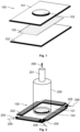
- Fig. 1 shows an example apparatus 100 which is configured to increase the concentration of an analyte in a pre-determined concentration area of a sample medium 105.
- the sample medium 105 is configured to take up the analyte solution, such that the analyte solution can move and/or flow around within the sample medium 105.
- the sample medium 105 may e.g., comprise cellulose.
- the apparatus 100 comprises plates 101, 102, in between which the sample medium 105 may be placed.
- the apparatus 100 comprises a first (and/or upper) plate 101 and a second (and/or lower) plate 102.
- the first plate 101 comprises an output opening 103, wherein the output opening 103 is positioned at the concentration area of the sample medium 105, i.e., the area of the sample medium 105, within which the concentration of the analyte is increased by the apparatus 100.
- the location of the output opening 103 within the first plate 101 defines the location of the concentration area. In particular, the location of the concentration area corresponds to the location of the output opening 103.
- the first and second plate 101, 102 form a housing of the apparatus 100, for taking up the sample medium 105.
- the first and the second plate 101, 102 may be coupled with one another using one or more sealing clamps 202.
- the sealing clamps 202 may be placed around the edges of the first and the second plate 101, 102.
- the sealing clamps 202 may be configured to press the first and the second plate 101, 102 together, such that the sample medium 105 is held in a defined and stable position and/or such that there is substantially no gap between the first plate 101 and the sample medium 105 and between the second plate 102 and the sample medium 105.
- the sealing clamps 202 at the edges of the first and the second plate 101, 102 may be part of the housing of the apparatus 100, for taking up the sample medium 105.
- the sealing clamps 202 may have a reduced length compared to the respective edges of the first and the second plate 101, 102, such that at the corners of the plates 101, 102 input openings 205 are created, wherein the input openings 205 allow a gaseous drying fluid 206, such as air, to enter the gap between the first and the second plate 101, 102.
- the housing of the apparatus 100 comprises input openings 205 which are configured to let a gaseous drying fluid 206 enter the interior of the housing, in which the sample medium 105 is located.
- the apparatus 100 shown in Fig. 2 is configured to generate a flow of gaseous drying fluid 205 through the sample medium 105 that is located between the two plates 101, 102.
- the flow of drying fluid 205 enters the sample medium 105 at remote ends (e.g., at the corners and/or the edges of the sample medium 105) and traverses the sample medium 105 towards the concentration area, before leaving the sample medium 105 at the concentration area of the sample medium 105 (wherein the concentration area is located below the output opening 103 of the first plate 101).
- the flow of drying fluid 206 is generated using a vacuum pump (not shown) which is coupled to a vacuum nozzle 200 that is placed above the output opening 103 of the first plate 101.
- the vacuum pump may be coupled to the vacuum nozzle 200 using a connector 201.
- the drying fluid 206 e.g., air
- the drying fluid 206 is sucked through the output opening 103 of the first plate 101, thereby creating a depression at the output opening 103 of the first plate 101.
- This depression causes gaseous drying fluid 206 and analyte solution to be sucked through the sample medium 105 towards the output opening 103, thereby increasing the amount of analyte solution at the concentration area (compared to the amount of analyte solution in the remote areas of the sample medium 105).
- the depression at the output opening 103 and the flow of drying fluid out of the sample medium 105 and through the output opening 103 causes the liquid component of the analyte solution (e.g., water) to be evaporated at the concentration area, thereby gradually increasing the concentration of the analyte at the concentration area.
- the analyte solution e.g., water
- the flow of gaseous drying fluid 206 may be maintained for a certain time duration (e.g., until the sample medium 105 is substantially dry). Typically, increasing the time duration increase the concentration of the analyte within the concentration area, until reaching a certain saturation level.
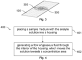
- Fig. 3 shows a sample medium 105 subsequent to processing within the preconcentration apparatus 100. In can be seen that the concentration of analyte is increased within the opening area 303 of the sample medium 105, which corresponds to the output opening 103 of the first plate 101. Furthermore, the concentration area 300 is illustrated, which exhibits a particularly high concentration of the analyte. The concentration area 300 may be located at the center of the opening area 303.
- a preconcentration method which does not subject the liquid sample to relatively extreme conditions of temperature and/or voltage.
- a preconcentration medium 105 such as cellulose
- Preconcentration may be achieved with multiple different types of medium. Preconcentration of factors 80 to 170 times of the initial sample concentration may be achieved for sample analytes that are dissolved in liquid water. Samples of relatively low volume that contain a mix of solid and liquids can be preconcentrated using the preconcentration method which is described herein.
- a sample soaked cellulose medium 105 is sandwiched between two plates 101, 102. Subsequently, a vacuum is applied during the procedure.
- Fig. 3 shows the resulting preconcentrated sample analyte distribution.
- the preconcentration method comprises the following steps.
- a sample soaked cellulose substrate 105 is clamped between two acrylic sheets 101, 102, the top sheet 101 having a hole 103 in it.
- a vacuum e.g., of pressure 80 kPa (-20 kPa compared to atmospheric pressure) is effected with a vacuum nozzle 200 for a certain time duration (e.g., 30 min) until complete evaporation of the liquid is achieved.
- the (possibly cellulose) sample medium 105 may have one or more of the following roles:
- the (possibly acrylic) plates 101, 102 may have one or more of the following roles:
- the vacuum pump is the primary driver of the preconcentration and isolates the preconcentration area 300, 303 to a location within the sample medium 105, wherein the preconcentration area 300, 303 is delineated by the hole 103 in the plate 105.
- the pump may be configured to supplement a 80 kPa vacuum through the nozzle connection 200, 201 to the plate 101.
- the (possibly) acrylic plates 101, 102 may have dimensions 15 by 10 cm and/or a thickness of 3 mm.
- the hole 103 in the top plate 101 may have a diameter of 16 mm.
- the diameter of the hole 103 is preferably narrower and/or smaller than the width of the sampling medium 105 to constrain all liquid flow to be within the sampling medium 105.
- Bull clips may be used as clamps 202 to constrain the sampling medium 105 to be flat and held between the plates 101, 102.
- Fig. 4 shows a flow chart of an example method 400 for increasing the concentration of an analyte within a liquid solution.
- the method 400 comprises placing 401 a (fibrous) sample medium 105 which is imbibed with the liquid solution into the interior of a housing 101, 102, 202.
- the housing 101, 102, 202 may comprise two plates 101, 102 (one on each side of the sample medium 105), which are configured to apply a pressure onto the sample medium 105 (to hold the sample medium 105 in a fixed position).
- the method 400 further comprises generating 402 a flow of gaseous fluid 206 (e.g., of air) through the interior of the housing 101, 102, 202 towards an output opening 103 of the housing 101, 102, 202, such that the liquid solution is moved within the (fibrous) sample medium 105 towards a concentration area 300, 303 of the sample medium 105, wherein the concentration area 300, 303 is located at the output opening 103 of the housing 101, 102, 202.
- the output opening 103 may be a hole in the first plate 101 of the housing 101, 102, 105.
- a pressure may be caused onto the sample medium 105 using the first plate 101 and the second plate 102 of the housing 101, 102, 202.
- the sample medium 105 is prevented from being moved by the flow of gaseous fluid 206.
- the flow of gaseous fluid 206 is forced to flow through the sample medium 105.
- the liquid solution is moved towards the concentration area 303, 303. Furthermore, the liquid (e.g., the water) within the liquid solution evaporates at the concentration area 300, 303. As a result of this, the concentration of the analyte is increased in a localized manner within the concentration area 300, 303.
- the concentration area 300, 303 may represent 10% or less of the surface of the sample medium 105.
Landscapes
- Health & Medical Sciences (AREA)
- Life Sciences & Earth Sciences (AREA)
- Chemical & Material Sciences (AREA)
- General Health & Medical Sciences (AREA)
- Physics & Mathematics (AREA)
- Analytical Chemistry (AREA)
- Biochemistry (AREA)
- General Physics & Mathematics (AREA)
- Immunology (AREA)
- Pathology (AREA)
- Food Science & Technology (AREA)
- Medicinal Chemistry (AREA)
- Engineering & Computer Science (AREA)
- Sampling And Sample Adjustment (AREA)
Abstract
A preconcentration apparatus (100) is described, which is configured to increase the concentration of an analyte within a liquid solution. The apparatus (100) comprises a housing (101, 102, 202) which encloses an interior that is configured to take up a sample medium (105) imbibed with the liquid solution of the analyte. The apparatus (100) is configured to generate a flow of gaseous fluid (206) through the interior of the housing (101, 102, 202) towards an output opening (103) of the housing (101, 102, 202), such that the liquid solution is moved within the sample medium (105) towards a concentration area (300, 303) of the sample medium (105), which is located at the output opening (103) of the housing (101, 102, 202).
Description
- The present document relates to a method and a corresponding apparatus, which are directed at increasing the concentration of an analyte within a liquid solution.
- Natural or treated water may comprise contaminants such as microplastics and/or perfluoroalkyl substances (PFAS). Monitoring the quality of water, notably of drinking water, typically involves measuring the concentration of such contaminants within the water. The concentration of a contaminant may be relatively low, and may therefore be difficult to measure.
- Hence, it may be beneficial to increase the concentration of a contaminant, i.e., of an analyte, within the water, i.e., within a liquid solution, in a defined way, thereby enabling a precise measurement of the concentration. The present document addresses the technical problem of increasing the concentration of an analyte within a liquid solution in a defined way, without impacting the stability of the analyte. The technical problem is solved by each one of the independent claims. Preferred examples are described in the dependent claims.
- According to an aspect, a preconcentration apparatus is described, which is configured to increase the concentration of an analyte within a liquid solution. Example analytes are a contaminant such as a microplastic, a pesticide and/or a PFAS. The liquid solution may comprise water.
- The apparatus comprises a housing which encloses an interior that is configured to take up a sample medium imbibed with the liquid solution of the analyte. The sample medium may be configured to guide liquid (notably towards the output opening of the housing). The sample medium may comprise fibers and/or may comprise a fibrous material. In particular, the sample medium may comprise cellulose.
- The apparatus is configured to generate a flow of gaseous fluid (e.g., of air) through the interior of the housing towards the (possibly single) output opening of the housing, such that the liquid solution is moved within the sample medium towards a concentration area of the sample medium, wherein the concentration area is located at (e.g., directly adjacent to and/or facing) the output opening of the housing. The concentration area may correspond to 10% or less of the surface of the sample medium.
- The liquid solution may be pushed by the gaseous fluid towards the output opening of the housing. At the output opening the liquid may evaporate, thereby leaving behind the analyte within the sample medium. This process may be continued for a certain (possibly predefined) time duration, notably until a substantial fraction (e.g., 90% or more) of the liquid solution has evaporated from the sample medium.
- As a result of this, a substantial increase of the concentration of the analyte may be achieved by
- concentrating the liquid solution within a relatively small concentration area; and
- evaporating the liquid from the liquid solution.
- The housing typically comprises one or more input openings which are each configured to guide gaseous fluid into the interior of the housing, whereas the (single) output opening is configured to guide gaseous fluid out of the interior of the housing. The one or more input openings are each located at a remote and/or opposite side of the housing with respect to the output opening. As a result of this, a flow of gaseous fluid through the entire sample medium is caused, thereby further increasing the concentration of the analyte.
- The apparatus may comprise a vacuum pump which is configured to suck gaseous fluid through the output opening out of the interior of the housing, thereby increasing the concentration of the analyte in a particularly reliable manner.
- The housing is preferably configured to apply a pressure onto the sample medium which is placed within the interior of the housing. As a result of this, the sample medium is prevented from being moved by the flow of gaseous fluid. Furthermore, the flow of gaseous fluid is forced to flow through the sample medium. By doing this, the concentration of the analyte may be increased in a particularly reliable manner.
- The housing may comprise a first plate and a second plate, which are located on opposite sides of the sample medium. The two plates may be pressed towards each other, to apply a pressure onto the sample medium. The first plate and the second plate may each be made up of acrylic. The housing may comprise one or more clamps configured to press the first plate and the second plate towards each other. The output opening may be implemented as a hole within the first plate. The one or more input openings may be located at the edge of the first plate and of the second plate. Furthermore, the one or more input openings may be formed by the gap between the first plate and the second plate. As a result of this, a particularly efficient and reliable preconcentration apparatus may be provided.
- According to a further aspect, a method for increasing the concentration of an analyte within a liquid solution is described. The method comprises placing a sample medium imbibed with the liquid solution into the interior of a housing. Furthermore, the method comprises generating a flow of gaseous fluid through the interior of the housing towards an output opening of the housing, such that the liquid solution is moved within the sample medium towards a concentration area of the sample medium, which is located at the output opening of the housing. The method may further comprise causing a pressure onto the sample medium (e.g., using a first plate and a second plate of the housing), such that the sample medium is prevented from being moved by the flow of gaseous fluid, and/or such that the flow of gaseous fluid is forced to flow through the sample medium.
- It should be noted that the methods and systems including its preferred embodiments as outlined in the present document may be used stand-alone or in combination with the other methods and systems disclosed in this document. In addition, the features outlined in the context of an apparatus are also applicable to a corresponding method. Furthermore, all aspects of the method and apparatus outlined in the present document may be arbitrarily combined. In particular, the features of the claims may be combined with one another in an arbitrary manner.
- The invention is explained below in an exemplary manner with reference to the accompanying drawings, wherein
- Figure 1
- illustrates a housing for a sample medium of the analyte solution, wherein the housing comprises an output opening at a concentration area of the sample medium;
- Figure 2
- shows the use of a vacuum pump for generating a flow of a gaseous drying fluid through the interior of the housing;
- Figure 3
- illustrated the sample medium with an increased concentration of the analyte at the concentration area; and
- Figure 4
- shows a flow chart of an example method for increasing the concentration of an analyte.
- As outlined above, the present document is directed at increasing the concentration of an analyte within an analyte and/or liquid solution in an efficient, precise and deterministic manner. In this context,
Fig. 1 shows anexample apparatus 100 which is configured to increase the concentration of an analyte in a pre-determined concentration area of asample medium 105. Thesample medium 105 is configured to take up the analyte solution, such that the analyte solution can move and/or flow around within thesample medium 105. Thesample medium 105 may e.g., comprise cellulose. - The
apparatus 100 comprisesplates sample medium 105 may be placed. In particular, theapparatus 100 comprises a first (and/or upper)plate 101 and a second (and/or lower)plate 102. Thefirst plate 101 comprises an output opening 103, wherein theoutput opening 103 is positioned at the concentration area of thesample medium 105, i.e., the area of thesample medium 105, within which the concentration of the analyte is increased by theapparatus 100. The location of the output opening 103 within thefirst plate 101 defines the location of the concentration area. In particular, the location of the concentration area corresponds to the location of theoutput opening 103. The first andsecond plate apparatus 100, for taking up thesample medium 105. - As illustrated in
Fig. 2 , the first and thesecond plate second plate second plate sample medium 105 is held in a defined and stable position and/or such that there is substantially no gap between thefirst plate 101 and thesample medium 105 and between thesecond plate 102 and thesample medium 105. The sealing clamps 202 at the edges of the first and thesecond plate apparatus 100, for taking up thesample medium 105. - The sealing clamps 202 may have a reduced length compared to the respective edges of the first and the
second plate plates input openings 205 are created, wherein theinput openings 205 allow agaseous drying fluid 206, such as air, to enter the gap between the first and thesecond plate apparatus 100 comprisesinput openings 205 which are configured to let agaseous drying fluid 206 enter the interior of the housing, in which thesample medium 105 is located. - The
apparatus 100 shown inFig. 2 is configured to generate a flow of gaseous dryingfluid 205 through thesample medium 105 that is located between the twoplates fluid 205 enters thesample medium 105 at remote ends (e.g., at the corners and/or the edges of the sample medium 105) and traverses thesample medium 105 towards the concentration area, before leaving thesample medium 105 at the concentration area of the sample medium 105 (wherein the concentration area is located below theoutput opening 103 of the first plate 101). In the example shown inFig. 2 , the flow of dryingfluid 206 is generated using a vacuum pump (not shown) which is coupled to avacuum nozzle 200 that is placed above theoutput opening 103 of thefirst plate 101. The vacuum pump may be coupled to thevacuum nozzle 200 using aconnector 201. - Using the vacuum pump, the drying fluid 206 (e.g., air) is sucked through the
output opening 103 of thefirst plate 101, thereby creating a depression at theoutput opening 103 of thefirst plate 101. This depression causes gaseous dryingfluid 206 and analyte solution to be sucked through thesample medium 105 towards theoutput opening 103, thereby increasing the amount of analyte solution at the concentration area (compared to the amount of analyte solution in the remote areas of the sample medium 105). Furthermore, the depression at theoutput opening 103 and the flow of drying fluid out of thesample medium 105 and through theoutput opening 103 causes the liquid component of the analyte solution (e.g., water) to be evaporated at the concentration area, thereby gradually increasing the concentration of the analyte at the concentration area. - The flow of gaseous drying
fluid 206 may be maintained for a certain time duration (e.g., until thesample medium 105 is substantially dry). Typically, increasing the time duration increase the concentration of the analyte within the concentration area, until reaching a certain saturation level.Fig. 3 shows asample medium 105 subsequent to processing within thepreconcentration apparatus 100. In can be seen that the concentration of analyte is increased within theopening area 303 of thesample medium 105, which corresponds to theoutput opening 103 of thefirst plate 101. Furthermore, theconcentration area 300 is illustrated, which exhibits a particularly high concentration of the analyte. Theconcentration area 300 may be located at the center of theopening area 303. - Hence, a preconcentration method is described, which does not subject the liquid sample to relatively extreme conditions of temperature and/or voltage. A preconcentration medium 105 (such as cellulose) may be used, which is easily available. Preconcentration may be achieved with multiple different types of medium. Preconcentration of factors 80 to 170 times of the initial sample concentration may be achieved for sample analytes that are dissolved in liquid water. Samples of relatively low volume that contain a mix of solid and liquids can be preconcentrated using the preconcentration method which is described herein.
- In the described preconcentration procedure a sample soaked
cellulose medium 105 is sandwiched between twoplates Fig. 3 shows the resulting preconcentrated sample analyte distribution. - The preconcentration method comprises the following steps. In a first step, a sample soaked
cellulose substrate 105 is clamped between twoacrylic sheets top sheet 101 having ahole 103 in it. A vacuum, e.g., of pressure 80 kPa (-20 kPa compared to atmospheric pressure), is effected with avacuum nozzle 200 for a certain time duration (e.g., 30 min) until complete evaporation of the liquid is achieved. - The (possibly cellulose)
sample medium 105 may have one or more of the following roles: - The
sample medium 105 controls the direction into which the sample is able to flow. - The
sample medium 105 influences the directional flow of the liquid solution due to the orientation of (possibly cellulose) fibres. - The (possibly cellulose) fibre spacing determines the filtration effectiveness of the
sampling medium 105. Hence, thesample medium 105 may be configured to filter out (relatively large) components which are carried by the liquid solution. - The (possibly acrylic)
plates - The
plates sampling medium 105 flat. - The
hole 103 in thetop plate 101 restricts the flow of the liquid solution driven byair 206. This delineates the sampleanalyte preconcentration area sample medium 105. - The vacuum pump is the primary driver of the preconcentration and isolates the
preconcentration area sample medium 105, wherein thepreconcentration area hole 103 in theplate 105. The pump may be configured to supplement a 80 kPa vacuum through thenozzle connection plate 101. - The (possibly)
acrylic plates hole 103 in thetop plate 101 may have a diameter of 16 mm. The diameter of thehole 103 is preferably narrower and/or smaller than the width of thesampling medium 105 to constrain all liquid flow to be within thesampling medium 105. Bull clips may be used asclamps 202 to constrain thesampling medium 105 to be flat and held between theplates -
Fig. 4 shows a flow chart of anexample method 400 for increasing the concentration of an analyte within a liquid solution. Themethod 400 comprises placing 401 a (fibrous)sample medium 105 which is imbibed with the liquid solution into the interior of ahousing housing plates 101, 102 (one on each side of the sample medium 105), which are configured to apply a pressure onto the sample medium 105 (to hold thesample medium 105 in a fixed position). - The
method 400 further comprises generating 402 a flow of gaseous fluid 206 (e.g., of air) through the interior of thehousing output opening 103 of thehousing sample medium 105 towards aconcentration area sample medium 105, wherein theconcentration area output opening 103 of thehousing output opening 103 may be a hole in thefirst plate 101 of thehousing - As indicated above, a pressure may be caused onto the
sample medium 105 using thefirst plate 101 and thesecond plate 102 of thehousing sample medium 105 is prevented from being moved by the flow ofgaseous fluid 206. Furthermore, the flow ofgaseous fluid 206 is forced to flow through thesample medium 105. - The liquid solution is moved towards the
concentration area concentration area concentration area concentration area sample medium 105. - It should be noted that the description and drawings merely illustrate the principles of the proposed methods and systems. Those skilled in the art will be able to implement various arrangements that, although not explicitly described or shown herein, embody the principles of the invention and are included within its spirit and scope. Furthermore, all examples and embodiment outlined in the present document are principally intended expressly to be only for explanatory purposes to help the reader in understanding the principles of the proposed methods and systems. Furthermore, all statements herein providing principles, aspects, and embodiments of the invention, as well as specific examples thereof, are intended to encompass equivalents thereof.
Claims (12)
- A preconcentration apparatus (100) which is configured to increase a concentration of an analyte within a liquid solution; wherein- the apparatus (100) comprises a housing (101, 102, 202) which encloses an interior that is configured to take up a sample medium (105) imbibed with the liquid solution of the analyte; and- the apparatus (100) is configured to generate a flow of gaseous fluid (206) through the interior of the housing (101, 102, 202) towards an output opening (103) of the housing (101, 102, 202), such that the liquid solution is moved within the sample medium (105) towards a concentration area (300, 303) of the sample medium (105), which is located at the output opening (103) of the housing (101, 102, 202).
- The preconcentration apparatus (100) of claim 1, wherein- the housing (101, 102, 202) comprises one or more input openings (205) which are each configured to guide gaseous fluid (206) into the interior of the housing (101, 102, 202);- the output opening (103) is configured to guide gaseous fluid (206) out of the interior of the housing (101, 102, 202); and- the one or more input openings (205) are each located at a remote and/or opposite side of the housing (101, 102, 202) with respect to the output opening (103).
- The preconcentration apparatus (100) of any previous claim, wherein the apparatus (100) comprise a vacuum pump configured to suck gaseous fluid (206) through the output opening (103) out of the interior of the housing (101, 102, 202).
- The preconcentration apparatus (100) of any previous claim, wherein the housing (101, 102, 202) is configured to apply a pressure onto the sample medium (105) which is placed within the interior of the housing (101, 102, 202), such that- the sample medium (105) is prevented from being moved by the flow of gaseous fluid (206); and- the flow of gaseous fluid (206) is forced to flow through the sample medium (105).
- The preconcentration apparatus (100) of any previous claim, wherein the housing (101, 102, 202) comprises a first plate (101) and a second plate (102), which are located on opposite sides of the sample medium (105) and which are pressed towards each other, to apply a pressure onto the sample medium (105).
- The preconcentration apparatus (100) of claim 5, wherein the housing (101, 102, 202) comprises one or more clamps (202) configured to press the first plate (101) and the second plate (102) towards each other.
- The preconcentration apparatus (100) of any of claims 5 to 6, wherein the output opening (103) is a hole within the first plate (101).
- The preconcentration apparatus (100) of any of claims 5 to 7, wherein the first plate (101) and the second plate (102) are each made up of acrylic.
- The preconcentration apparatus (100) of any of claims 5 to 8, wherein the housing (101, 102, 202) comprises one or more input openings (205) which- are located at an edge of the first plate (101) and of the second plate (102); and/or- are formed by a gap between the first plate (101) and the second plate (102).
- The preconcentration apparatus (100) of any previous claim, wherein- the sample medium (105) is configured to guide liquid;- the sample medium (105) comprises fibers and/or comprises a fibrous material; and/or- the sample medium (105) comprises cellulose.
- A method (400) for increasing a concentration of an analyte within a liquid solution; wherein the method (400) comprises- placing (401) a sample medium (105) imbibed with the liquid solution into an interior of a housing (101, 102, 202); and- generating (402) a flow of gaseous fluid (206) through the interior of the housing (101, 102, 202) towards an output opening (103) of the housing (101, 102, 202), such that the liquid solution is moved within the sample medium (105) towards a concentration area (300, 303) of the sample medium (105), which is located at the output opening (103) of the housing (101, 102, 202).
- The method (400) of claims 11, wherein the method (400) comprises causing a pressure onto the sample medium (105) using a first plate (101) and a second plate (102) of the housing (101, 102, 202), such that- the sample medium (105) is prevented from being moved by the flow of gaseous fluid (206); and- the flow of gaseous fluid (206) is forced to flow through the sample medium (105).
Priority Applications (1)
| Application Number | Priority Date | Filing Date | Title |
|---|---|---|---|
| EP23196008.9A EP4521095A1 (en) | 2023-09-07 | 2023-09-07 | Method and apparatus for concentrating an analyte |
Applications Claiming Priority (1)
| Application Number | Priority Date | Filing Date | Title |
|---|---|---|---|
| EP23196008.9A EP4521095A1 (en) | 2023-09-07 | 2023-09-07 | Method and apparatus for concentrating an analyte |
Publications (1)
| Publication Number | Publication Date |
|---|---|
| EP4521095A1 true EP4521095A1 (en) | 2025-03-12 |
Family
ID=87971849
Family Applications (1)
| Application Number | Title | Priority Date | Filing Date |
|---|---|---|---|
| EP23196008.9A Withdrawn EP4521095A1 (en) | 2023-09-07 | 2023-09-07 | Method and apparatus for concentrating an analyte |
Country Status (1)
| Country | Link |
|---|---|
| EP (1) | EP4521095A1 (en) |
Citations (8)
| Publication number | Priority date | Publication date | Assignee | Title |
|---|---|---|---|---|
| US5698774A (en) * | 1996-08-30 | 1997-12-16 | Safety-Kleen Corp. | Apparatus and method for determining concentrations of oil or other non-volatile contaminants in cleaning solvents |
| EP1454121A1 (en) * | 2001-11-19 | 2004-09-08 | Biosensor Applications Sweden AB | Transfer of a sample from a solid support into a liquid. |
| US20050252859A1 (en) * | 2004-05-13 | 2005-11-17 | Bruker Biospin Gmbh | Drying SPE cartridges |
| US20080241956A1 (en) * | 2007-03-30 | 2008-10-02 | Fujifilm Corporation | Method for detecting analyte and biochip |
| US20080311672A1 (en) * | 2007-06-12 | 2008-12-18 | Dionex Corporation | Membrane based concentrators |
| US9709582B1 (en) * | 2015-01-18 | 2017-07-18 | Hound Labs, Inc. | Method for target substance detection and measurement |
| WO2020076330A1 (en) * | 2018-10-11 | 2020-04-16 | Xinova, LLC | Concentration of water contaminants via rapid dispensing by microdispenser |
| WO2023060006A2 (en) * | 2021-09-28 | 2023-04-13 | The Regents Of The University Of California | Methods and devices for using airflow-driven, evaporative gradients |
-
2023
- 2023-09-07 EP EP23196008.9A patent/EP4521095A1/en not_active Withdrawn
Patent Citations (8)
| Publication number | Priority date | Publication date | Assignee | Title |
|---|---|---|---|---|
| US5698774A (en) * | 1996-08-30 | 1997-12-16 | Safety-Kleen Corp. | Apparatus and method for determining concentrations of oil or other non-volatile contaminants in cleaning solvents |
| EP1454121A1 (en) * | 2001-11-19 | 2004-09-08 | Biosensor Applications Sweden AB | Transfer of a sample from a solid support into a liquid. |
| US20050252859A1 (en) * | 2004-05-13 | 2005-11-17 | Bruker Biospin Gmbh | Drying SPE cartridges |
| US20080241956A1 (en) * | 2007-03-30 | 2008-10-02 | Fujifilm Corporation | Method for detecting analyte and biochip |
| US20080311672A1 (en) * | 2007-06-12 | 2008-12-18 | Dionex Corporation | Membrane based concentrators |
| US9709582B1 (en) * | 2015-01-18 | 2017-07-18 | Hound Labs, Inc. | Method for target substance detection and measurement |
| WO2020076330A1 (en) * | 2018-10-11 | 2020-04-16 | Xinova, LLC | Concentration of water contaminants via rapid dispensing by microdispenser |
| WO2023060006A2 (en) * | 2021-09-28 | 2023-04-13 | The Regents Of The University Of California | Methods and devices for using airflow-driven, evaporative gradients |
Non-Patent Citations (1)
| Title |
|---|
| WANG EDWARD ET AL: "Using airflow-driven, evaporative gradients to improve sensitivity and fluid control in colorimetric paper-based assays", LAB ON A CHIP, vol. 21, no. 21, 1 January 2021 (2021-01-01), UK, pages 4249 - 4261, XP093078933, ISSN: 1473-0197, Retrieved from the Internet <URL:http://pubs.rsc.org/en/content/articlepdf/2021/LC/D1LC00542A> DOI: 10.1039/D1LC00542A * |
Similar Documents
| Publication | Publication Date | Title |
|---|---|---|
| JP3133328B2 (en) | Viable count method | |
| US5580434A (en) | Interface apparatus for capillary electrophoresis to a matrix-assisted-laser-desorption-ionization mass spectrometer | |
| JP3915677B2 (en) | Chip for mass spectrometry, laser desorption ionization time-of-flight mass spectrometer and mass spectrometry system using the same | |
| WO2019102350A1 (en) | Methods and systems utilizing ultrasound-assisted sampling interfaces for mass spectrometric analysis | |
| EP0773055A2 (en) | Method and apparatus for handling particles by acoustic radiation | |
| US20110114837A1 (en) | Ion mobility spectrometer | |
| EP3714480B1 (en) | Methods and systems for feedback control of direct sampling interfaces for mass spectrometric analysis | |
| JPH06318445A (en) | Sample holder for electron microscope | |
| GB2349349A (en) | Variable volume vessel for assay purposes | |
| CN102448602A (en) | Microfluidic chip and gas-liquid phase separation method using the microfluidic chip | |
| KR20180106950A (en) | Separation of liquid in droplets and sedimented material enclosed therein | |
| CN107589571A (en) | The detection means and detection method of panel frame glue intensity | |
| JP2010533841A (en) | Test patch apparatus and method | |
| CN107924799B (en) | The observation auxiliary unit of charged particle microscope and the sample observation method for using the observation auxiliary unit | |
| CN113049546B (en) | A microfluidic ion detection chip with bubble brightening structure and detection method thereof | |
| EP1486777B1 (en) | Sensor format and construction method for capillary-filled diagnostic sensor | |
| WO2020044564A1 (en) | Analysis method, analysis device, and program | |
| JP4241006B2 (en) | Laser desorption ionization mass spectrometry method and sample plate used therefor | |
| CN107796862A (en) | External pressurized Capillary Electrophoresis interface arrangement and the method for detecting material | |
| US20090074619A1 (en) | Device for measuring total organic carbon | |
| KR20090007031A (en) | Vacuum Chuck of Polarizing Film Inspection System | |
| JPH03224602A (en) | Device for adjusting dissolved gas concentration in liquid | |
| JP5544759B2 (en) | Sample analysis method using mass spectrometry | |
| US7935536B2 (en) | System for water removal and solvent evaporation | |
| CN114509463B (en) | A method for preparing double samples based on transmission electron microscope support film |
Legal Events
| Date | Code | Title | Description |
|---|---|---|---|
| PUAI | Public reference made under article 153(3) epc to a published international application that has entered the european phase |
Free format text: ORIGINAL CODE: 0009012 |
|
| STAA | Information on the status of an ep patent application or granted ep patent |
Free format text: STATUS: THE APPLICATION HAS BEEN PUBLISHED |
|
| AK | Designated contracting states |
Kind code of ref document: A1 Designated state(s): AL AT BE BG CH CY CZ DE DK EE ES FI FR GB GR HR HU IE IS IT LI LT LU LV MC ME MK MT NL NO PL PT RO RS SE SI SK SM TR |
|
| STAA | Information on the status of an ep patent application or granted ep patent |
Free format text: STATUS: THE APPLICATION IS DEEMED TO BE WITHDRAWN |
|
| 18D | Application deemed to be withdrawn |
Effective date: 20250913 |