EP4521042A1 - Refrigerating apparatus and method for assembling a refrigerating apparatus - Google Patents
Refrigerating apparatus and method for assembling a refrigerating apparatus Download PDFInfo
- Publication number
- EP4521042A1 EP4521042A1 EP24196350.3A EP24196350A EP4521042A1 EP 4521042 A1 EP4521042 A1 EP 4521042A1 EP 24196350 A EP24196350 A EP 24196350A EP 4521042 A1 EP4521042 A1 EP 4521042A1
- Authority
- EP
- European Patent Office
- Prior art keywords
- cover
- rear wall
- plug
- refrigerating apparatus
- plug structures
- Prior art date
- Legal status (The legal status is an assumption and is not a legal conclusion. Google has not performed a legal analysis and makes no representation as to the accuracy of the status listed.)
- Pending
Links
Images



Classifications
-
- F—MECHANICAL ENGINEERING; LIGHTING; HEATING; WEAPONS; BLASTING
- F25—REFRIGERATION OR COOLING; COMBINED HEATING AND REFRIGERATION SYSTEMS; HEAT PUMP SYSTEMS; MANUFACTURE OR STORAGE OF ICE; LIQUEFACTION SOLIDIFICATION OF GASES
- F25D—REFRIGERATORS; COLD ROOMS; ICE-BOXES; COOLING OR FREEZING APPARATUS NOT OTHERWISE PROVIDED FOR
- F25D23/00—General constructional features
- F25D23/06—Walls
- F25D23/069—Cooling space dividing partitions
-
- F—MECHANICAL ENGINEERING; LIGHTING; HEATING; WEAPONS; BLASTING
- F25—REFRIGERATION OR COOLING; COMBINED HEATING AND REFRIGERATION SYSTEMS; HEAT PUMP SYSTEMS; MANUFACTURE OR STORAGE OF ICE; LIQUEFACTION SOLIDIFICATION OF GASES
- F25D—REFRIGERATORS; COLD ROOMS; ICE-BOXES; COOLING OR FREEZING APPARATUS NOT OTHERWISE PROVIDED FOR
- F25D23/00—General constructional features
- F25D23/06—Walls
- F25D23/065—Details
-
- F—MECHANICAL ENGINEERING; LIGHTING; HEATING; WEAPONS; BLASTING
- F25—REFRIGERATION OR COOLING; COMBINED HEATING AND REFRIGERATION SYSTEMS; HEAT PUMP SYSTEMS; MANUFACTURE OR STORAGE OF ICE; LIQUEFACTION SOLIDIFICATION OF GASES
- F25D—REFRIGERATORS; COLD ROOMS; ICE-BOXES; COOLING OR FREEZING APPARATUS NOT OTHERWISE PROVIDED FOR
- F25D23/00—General constructional features
- F25D23/06—Walls
- F25D23/065—Details
- F25D23/067—Supporting elements
Definitions
- the present invention pertains to a refrigerating apparatus, in particular to a domestic refrigerating apparatus such as a refrigerator or a freezer.
- the invention further pertains to a method for assembling a refrigerating apparatus.
- a storage compartment where food or other items are stored, is cooled by circulating air between the storage compartment and an evaporator chamber in which an evaporator as part of a coolant circuit is accommodated.
- a cover is positioned adjacent to a rear wall of the storage compartment, wherein the cover defines cooling channels that direct the air along the rear wall towards exhaust openings that open into the storage compartment.
- DE 10 2020 203 080 A1 discloses a refrigerator comprising a container that defines a storage compartment, and a cover that defines air distribution channels for distributing air within the storage compartment.
- the cover is attached to a rear wall of the container through four snap fit connections on the cover and four matching snap fit connections on the rear wall.
- a fixing shaft with a head protrudes from the rear wall, which is introduced in a form fitting manner into an undercut recess of the cover.
- the head and shaft are first introduced into the recess of the cover by moving the cover in a direction perpendicular to the rear wall. Subsequently, the cover is moved parallel to the rear wall to insert the head into the undercut of the recess and to engage the snap fit connections of the cover and the rear wall.
- a further refrigerator comprising a cover attached to a rear wall of a storage compartment is described in WO 2019 / 233760 A1 .
- the present invention provides a refrigerating apparatus in accordance with claim 1, and a method in accordance with claim 15.
- Advantageous embodiments are subject to the dependent claims and the description, referring to the drawings.
- a refrigerating apparatus includes a container that defines a storage compartment for receiving items to be cooled, the container including a rear wall, which has an inner surface facing the storage compartment, wherein multiple first plug structures are formed on the inner surface along a perimeter of the rear wall.
- the refrigerating apparatus further includes a cover having a first surface that faces the storage compartment, and an opposite second surface that faces the inner surface of the rear wall. Channels for directing an air flow to a perimeter of the cover are defined between the cover and the rear wall.
- Multiple second plug structures are formed integrally with the cover on the side of the second surface along the perimeter of the cover.
- Each of the first plug structures is configured for being positively connected to one of the second plug structures by engaging the first and second plug structures in a depth direction that extends transverse to the rear wall.
- a method for assembling a refrigerating apparatus according to the first aspect of the invention.
- the method includes positioning the cover in the storage compartment defined by the container so that each second plug structure of the cover faces one first plug structure of the rear wall of the container, and snapping together the first and second plug structures to fix the cover to the rear wall by moving the cover towards the rear wall along the depth direction.
- the cover and the rear wall with integrally formed fixing structures in the form of matching or corresponding snap fit connectors that allow snapping together the cover and the rear wall by moving the cover towards the rear wall only in one direction, i.e. without change in the direction of movement. Therefore, the rear wall is provided with first plug structures along its end regions or perimeter, and the cover, which may have a rectangular or substantially rectangular circumference or perimeter, is provided with second plug structures matching the first plug structures along its perimeter.
- the first and second plug structures may each define undercuts with respect to a depth direction perpendicular to the rear wall, wherein the undercuts of the first plug structures are formed complementary to the undercuts of the second plug structures so that the first and second plug structures are configured to engage in a form fitting fashion.
- One of the advantages of the present invention is that, due to the first and second plug structures being configured for being positively connected to each other by engaging the first and second plug structures in the depth direction fixing or attaching the cover to the rear wall can be achieved by simply moving the cover towards the rear wall, i.e. along the depth direction, without changing the direction of movement. Thereby, assembling is eased and, for example, may be easier performed by a robot or similar automated device.
- the refrigerating apparatus may be a domestic refrigerating apparatus such as a refrigerator, a freezer, or a combined refrigerator and freezer.
- the container may comprise a bottom and a ceiling that extend from the rear wall in the depth direction and are spaced to each other in a vertical direction.
- the container may comprise first and second sidewalls extending between the bottom and the ceiling in the vertical direction and being spaced in a transverse direction.
- the first plug structures may be formed by recesses of the inner surface, each recess defining an undercut with respect to the depth direction, and wherein the second plug structures are formed by elastic hooks, each hook being configured to snap into one of the undercuts.
- the hooks may, for example, include an elastic shaft protruding from second surface of the cover and a hook portion protruding laterally from the shaft.
- the hook portion is configured to engage into the undercut of the recess.
- the hook portion may comprise an included surface facing away from the second surface of the cover, said inclined surface being configured to slide along an edge of the recess to elastically bend or deform the shaft during movement of the cover towards the rear wall.
- the hooks and recesses provide an efficient and reliable snap-fit connection that can easily be assembled and is advantageous for equalizing tolerances in the positions of the first and second plug structures.
- a third plug structure may be arranged in a central region of the rear wall on its inner surface, and a fourth plug structure may be integrally formed with the cover and positioned on the side of the second surface in a central region of the cover, wherein the third plug structure is configured for being positively connected to the fourth plug structure by engaging the third and fourth plug structures in the depth direction.
- the third plug structure may include a shaft protruding from the inner surface of the rear wall and a head positioned on an end of the shaft facing away from the inner surface
- the fourth plug structure may include opposing elastic hooks configured to snap about and engage the head, e.g.by surrounding the head.
- the hooks each may have an elastic shaft and a hook portion protruding laterally from the shaft towards the respective other shaft. Thereby, the hooks may enclose or grip the head from opposing sides which makes the connection more reliable.
- the third plug structure may be formed separate from the rear wall and may be positioned in an opening of the rear wall.
- the shape of the container i.e. its rear wall
- the third plug structure may be formed as an insert in the required shape and simply mounted in the opening of the rear wall.
- the third plug structure includes a sealing that contacts an outer surface of the rear wall in a region surrounding the opening, wherein the outer surface of the rear wall is covered by an insulating foam.
- the container may be surrounded by an insulating foam.
- the foam is reliably prevented from entering the storage compartment by the sealing, which may be in the form of a sealing lip overlapping the outer surface of the rear wall. Further, the sealing is pressed against the outer surface of the rear wall by the foam and, thereby, is also held in position by the foam which further eases assembling of the apparatus.
- the cover has a substantially rectangular perimeter, with first sides extending along a vertical direction, for example along the side walls, and second sides extending along a transverse direction, for example along the ceiling and the bottom.
- At least two second plug structures may be arranged on each first side, wherein at least one second plug structure is arranged on one, preferably on only one of the second sides. That is, two or more plug structures may be provides on the vertical sides of the cover, wherein on the horizontal or transversely extending sides at least one plug structure may be positioned.
- the refrigerating apparatus may comprise a housing arranged on the rear wall of the container, the housing including at least one pin that is arranged in an upper end region of the housing.
- the cover may extend in a vertical direction, which is transverse to the depth direction, and has at least one recess formed in its first surface arranged in a lower end region with respect to the vertical direction.
- the upper end region of the housing overlaps the lower end region of the cover, and the pin of the housing engages the recess of the cover, wherein the housing is fixed to the container, e.g. by snap-fit connectors.
- the recess of the cover in the vertically lower end region into which the pin of the housing is inserted defines the position of the cover and the housing relative to each other. Further, the cover is clamped between the housing and the rear wall at its lower end region which further prevents unintended disassembling of the cover from the rear wall.
- the rear wall of the container may include a pocket formed in its inner surface, wherein the recess of the cover defines a protrusion on the second surface of the cover, and wherein the protrusion of the cover protrudes into the pocket of the rear wall.
- the housing together with a lower portion of the rear wall may define an evaporator chamber in which an evaporator is accommodated.
- the evaporator may be in the form of an MCHE evaporator, that is, a so called "Micro Channel Heat Exchanger".
- the evaporator is part of a coolant circuit in which coolant circulates, wherein the coolant evaporates and receives heat in the evaporator and condenses and discharges heat to the environment in a condenser.
- the evaporator chamber may be in fluid communication with the channels defined on the second surface of the cover.
- the channels may open into the storage compartment at the perimeter of the cover.
- a fan may be provided, e.g. in the space defined between the housing and the rear wall, the fan being configured to circulate air between the evaporator chamber and the storage compartment through the channels and a suction opening provided in the housing.
- the cover may include a cover member facing the storage compartment, and an insulating member arranged between the inner surface of the rear wall and the cover member, wherein the channels are defined between the cover member and the inner surface of the rear wall and/or between the insulating member and the inner surface of the rear wall.
- the cover member may be made of a plastic material and may have a thickness in a range between 0.8 mm and 2.5 mm.
- the second plug structures may be integrally formed with the cover member.
- snapping together the first and second plug structures may include linearly moving the cover in the depth direction.
- the cover may me moved along a curved trajectory, preferably a uniformly curved, e.g. circular trajectory, having a directional component parallel to the depth direction.
- Figs. 1 and 2 exemplarily shows a refrigerating apparatus 100 in the form of a domestic refrigerator. It should be understood the invention is not limited to refrigerators but may also be employed in freezers or similar. As visible from Figs. 1 and 2 , the refrigerating apparatus 100 includes a container 1, a cover 2, and an optional housing 3. Further, the refrigerating apparatus 100 comprises a coolant circuit of which only an evaporator 4 is shown in Fig. 2 .
- the container 1 defines a storage compartment 10 for receiving items to be cooled such as food, beverages, medicine or similar items.
- the container 1 includes a rear wall 11 extending in a vertical direction V and limiting the storage compartment with respect to a depth direction T that extends transverse to the vertical direction V. Further, the container 1 includes a bottom 14 and a ceiling 15, both extending in the depth direction T and limiting the storage compartment 10 with respect to the vertical direction V. Additionally, first sidewall 16 and second side wall 17 extend in the vertical direction V between the bottom 14 and the ceiling 15 and limit the storage compartment 10 with respect to a transverse direction C.
- the container 1, i.e. its walls [KI(1] may be formed from a plastic material, e.g. in a molding process, or from a metal material, e.g. in a deep drawing process.
- the cover 2 has an areal expanse. As shown in Fig. 1 , the cover 2 may have a substantially rectangular perimeter or circumference. As schematically shown in Fig. 2 , the cover 2 may substantially be plate shaped. In particular, the cover 2 may include a cover member 27 and an insulating member 28.
- the cover member 27 may be in the form of a plate having a first surface of the cover member 27a and a second surface of the cover member 27b.
- the cover member 27 may be made of a plastic material.
- a thickness of the cover member 27, measured between a first surface of the cover member 27a and a second surface of the cover member 27b, may be in a range between 0.8 mm and 2.5 mm.
- the insulating member 28 may be made of a thermally insulating material, e.g. of expanded polystyrol (EPS). The insulating member 28 is fixed, e.g. bonded, to the second surface of the cover member 27b.
- EPS expanded polystyrol
- the cover 2 is arranged on the rear wall 11 and, as will be explained in more detail below, is attached to the rear wall 11.
- the insulating member 28 faces an inner surface of the rear wall 11a
- the cover member 27 faces the storage compartment 10.
- the first surface of the cover member 27a forms a first surface of the cover 2a oriented towards the storage compartment 10.
- a second surface of the cover 2b oriented towards the inner surface of the rear wall 11a is partially formed by a surface of the insulating member 28 and by the second surface of the cover member 27b.
- a channel 20 is defined between the insulating member 28 and the rear wall 11.
- a channel 20 may be defined between the cover member 27 and the rear wall 11. Of course more than one channel 20 may be provided.
- the channels 20 are in fluid communication with the storage compartment 10 and are provided for directing an air flow to a perimeter of the cover 2. For example, as shown in Fig. 1 , the cover 2 may extend in the transverse direction C between the opposing sidewalls 16, 17, wherein a gap may be left between the respective sidewall 16, 17 and an edge of the cover 2. Through this gap, air may be discharged from the channels 20 into the storage compartment 10.
- the cover 2 is positioned on the rear wall 11 such that first or long sides of the rectangular perimeter extend in the vertical direction V and second or short sides of the rectangular perimeter extend in the transverse direction C.
- the cover 2 is attached to the rear wall 11 at multiple sites along its perimeter.
- the rear wall 11 and the cover 2 may be fixed to each other via multiple first plug structures 12 and second plug structures 22 along the perimeter of the rear wall 11 and the cover 2.
- central regions of the rear wall 11 and the cover 2 may be coupled by third plug structures 13 and fourth plug structures 23.
- three second plug structures 22 may be arranged on each first side of the cover 2, and on the second side of the cover 2 adjacent to the ceiling 15, two second plug structures 22 may be provided.
- a lower end region of the cover 2 facing the bottom 14 may be attached to the rear wall 11 by means of the housing 3 as will be explained in more detail below.
- Fig. 2 exemplarily shows two fourth plug structures 23 arranged in the central region of the cover 2. However, only one or more than two fourth plug structures 23 may be provided.
- Fig. 3 schematically illustrates attachment of the cover 2 in its vertically upper peripheral region to the rear wall 11.
- all first plug structures 12 and second plug structures 22 may be formed identically. Therefore, Fig. 3 is representative for all first plug structures 12 and second plug structures 22.
- the first plug structures 12 are formed on the inner surface of the rear wall 11a along a perimeter of the rear wall 11. As exemplarily shown in Fig. 3 , each first plug structure 12 may be formed by a recess of the inner surface of the rear wall 11a, wherein said recess defines an undercut 12A with respect to the depth direction T.
- the second plug structures 22 are integrally formed with the cover 2, in particular, with the second surface of the cover member 27b.
- the second plug structures 22 are formed integrally with the cover 2 on the side of the second surface of the cover 2b along the perimeter of the cover 2.
- the second plug structures 22 may be formed by elastic hooks, wherein each hook is configured to snap into one of the undercuts 12A.
- the hooks may, for example, include an elastic second shaft 22A protruding from second surface of the cover member 27b, and a first hook portion 22B protruding laterally from the second shaft 22A.
- the first hook portion 22B engages or protrudes into the undercut 12A of the recess.
- the cover 2 as a hole can be moved towards the rear wall 11 in a linear direction of movement DM, as shown in Fig. 7 , or along a curved trajectory as direction of movement DM, as shown in Fig. 8 .
- the hook snaps together with the recess and thereby attaches the cover 2 in a form fitting fashion to the rear wall 11.
- the first plug structure 12 is not limited to a recess, and the second plug structure 22 is not limited to a hook.
- each of the first plug structures 12 is configured for being positively connected to one of the second plug structures 22 by engaging the first plug structure 12 and second plug structures 22 in the depth direction T.
- Fig. 4 exemplarily shows attachment of the cover 2 in its central region to the rear wall 11 of the container 1.
- the third plug structure 13 is arranged in a central region of the rear wall 11 on the inner surface of the rear wall 11a.
- the third plug structure 13 may protrude from the inner surface of the rear wall 11a along the depth direction T, as exemplarily shown in Fig. 4 .
- the third plug structure 13 may include a first shaft 13A protruding from the inner surface of the rear wall 11a and a head 13B positioned on an end of the first shaft 13A facing away from the inner surface of the rear wall 11a.
- the first shaft 13A may, for example, be split into two second pins 131 that are elastically deformable so as to be able to approach each other.
- the head 13B generally, has a diameter larger than the first shaft 13A so that the head 13B laterally protrudes from the first shaft 13A.
- one third hook portion 132 may by formed on the end of each second pin 131, wherein the third hook portions 132 together form the head 13B.
- Fig. 4 shows a third plug structure 13 which is formed as a part separate from the rear wall 11.
- the third plug structure 13 may include a plate 133 from which the first shaft 13A protrudes, wherein the plate 133 is positioned on the inner surface of the rear wall 11a and covers an opening 11C formed in the rear wall 11.
- a sealing 13C may be formed on the circumference of the plate 133, wherein the sealing 13C extends through the opening 11D and contacts an outer surface of the rear wall 11b in a region surrounding the opening 11C.
- the sealing 13C may have a collar that extends through the opening 11C and a lip that laterally extends from the collar and contacts the outer surface of the rear wall 11b.
- the outer surface of the rear wall 11b may be covered by an insulating foam 6.
- the sealing 13C prevents that the foam 6 enters through the opening 11C of the rear wall.
- the foam rigidly attaches the third plug structure 13 to the rear wall.
- a third pin 134 may protrude from the plate 133 on a side opposite to the first shaft 13A into the foam material 6. Thereby, the third plug structure 13 is even more reliably held in position.
- the fourth plug structure 23 may be integrally formed with the second surface of the cover member 27b, as exemplarily shown in Fig. 4 .
- the fourth plug structure 23 may include opposing elastic hooks configured to snap about and engage the head 13B of the third plug structure 13.
- the hooks forming the third plug structure 13 for example, each may have an elastic third shaft 23A and a second hook portion 23B protruding laterally from the third shaft 23A towards the respective other third shaft 23A.
- the second hook portions 23B engage, i.e. clamp about the head 13B, namely the third hook portions 132 of the third plug structure 13.
- the third hook portions 132 of the third plug structure 13 and the second hook portions 23B of the fourth plug structure 23 slide on each other so that the third shafts 23A or second pins 131 elastically deform.
- the second hook portions 23B of the fourth plug structure 23 are moved beyond the third hook portions 132 of the third plug structure 13, the second hook portion 23B and third hook portions 132snap in and positively engage.
- the third plug structures 13 and fourth plug structures 23 are not limited to the configuration described above. Generally, the third plug structure 13 is configured for being positively connected to the fourth plug structure 23 by engaging the third plug structures 13 and fourth plug structures 23 in the depth direction T.
- Fig. 5 illustrates attachment of the cover 2 in its vertically lower peripheral region to the rear wall 11 of the container 1.
- the cover 2 in its lower end region, may be attached to the rear wall 11 by means of the housing 3.
- the housing 3, generally, is arranged on the rear wall 11 of the container 1 in a lower end portion of the rear wall 11 that faces the bottom 14.
- the housing 3 is attached or fixed to the container 1.
- snap fit connectors may be used to attach the housing 3 to the container 1.
- the housing 3, together with the lower end portion of the rear wall 11, defines an evaporator chamber 33, in which the evaporator 4 is accommodated.
- the evaporator chamber 33 is in fluid communication with the storage compartment 10, for example, through an intake opening 31, and with the channels 20, e.g. via an exhaust opening 32. Air may be conveyed through the evaporator chamber 33 by a fan 5.
- the fan 5 may suck air from the storage compartment 10 into the evaporator chamber 33 where the coolant flowing in the evaporator 4 draws heat from the air.
- the fan 5 further may discharge the air into the channels 20 from which it is exhausted again into the storage compartment 10.
- an upper end region of the housing 3, with respect to the vertical direction V, may overlap the lower end region of the cover 2.
- the cover member 27, in the lower end region may be formed to define multiple steps, to define a recess 25 on its first surface of the cover member 27a and a corresponding protrusion 26 on its second surface of the cover member 27b, as exemplarily shown in Fig. 5 .
- the cover 2 may have at least one recess 25 formed in its first surface of the cover 2a arranged in a lower end region with respect to the vertical direction V.
- the recess 25 of the cover 2 may optionally define a protrusion 26 on the second surface of the cover 2b.
- the housing 3 may comprise a first pin 30 in its upper end region, wherein the first pin 30 protrudes into the recess 25 of the cover.
- first plug structure 12 and second plug structure 22 are engaged or snapped together to fix the cover 2 to the rear wall 11.
- the cover 2 is moved towards the rear wall 11 along the depth direction T.
- This step of snapping together M2 may include linearly moving the cover 2 in the depth direction, as indicated in Fig. 6 by arrow of direction of movement DM indicating a linear path or direction of movement of the cover 2.
- the second plug structures 22, e.g. the hooks approach and engage the first plug structures 12, e.g. the recesses with the undercuts 12A.
- all first plug structure 12 and second plug structures 22 may be engaged at substantially simultaneously.
- the cover 2 may be moved in step of snapping together M2 along a curved trajectory having a directional component parallel to the depth direction T. As shown in Fig. 2 , this movement may be a rotational movement about an axis of rotation AR extending in the transverse direction C. Thereby, the second plug structures 22 adjacent to the axis of rotation AR are introduced smoothly into the respective first plug structures 12.
- the direction of movement is along the depth direction t, and the path of movement is continuous without changes in the direction.
- the cover 2 can be attached to the rear wall 11 easily in an automated process, e.g. carried out by a robot or similar.
- Step of snapping together M2 may include engaging or snapping together the third plug structures 13 and the fourth plug structures 23 by moving the cover 2 towards the rear wall 11 along the depth direction T as described above.
Landscapes
- Engineering & Computer Science (AREA)
- Chemical & Material Sciences (AREA)
- Combustion & Propulsion (AREA)
- Physics & Mathematics (AREA)
- Mechanical Engineering (AREA)
- Thermal Sciences (AREA)
- General Engineering & Computer Science (AREA)
- Cold Air Circulating Systems And Constructional Details In Refrigerators (AREA)
Abstract
A refrigerating apparatus includes a container that defines a storage compartment for receiving items to be cooled. The container includes a rear wall, which has an inner surface facing the storage compartment, wherein multiple first plug structures are formed on the inner surface along a perimeter of the rear wall. The refrigerating apparatus further includes a cover having a first surface that faces the storage compartment, and an opposite second surface that faces the inner surface of the rear wall. Channels for directing an air flow to a perimeter of the cover are defined between the cover and the rear wall. Multiple second plug structures are formed integrally with the cover on the side of the second surface along the perimeter of the cover. Each of the first plug structures is configured for being positively connected to one of the second plug structures by engaging the first and second plug structures in a depth direction that extends transverse to the rear wall.
Description
- The present invention pertains to a refrigerating apparatus, in particular to a domestic refrigerating apparatus such as a refrigerator or a freezer. The invention further pertains to a method for assembling a refrigerating apparatus.
- In today's domestic refrigerating appliances, a storage compartment, where food or other items are stored, is cooled by circulating air between the storage compartment and an evaporator chamber in which an evaporator as part of a coolant circuit is accommodated. To achieve a uniform distribution of cold air within the storage compartment, a cover is positioned adjacent to a rear wall of the storage compartment, wherein the cover defines cooling channels that direct the air along the rear wall towards exhaust openings that open into the storage compartment. This configuration of the appliance requires attaching the cover to the rear wall or another part of the container that defines the storage compartment.
-
DE 10 2020 203 080 A1 - A further refrigerator comprising a cover attached to a rear wall of a storage compartment is described in
WO 2019 / 233760 A1 . - It is one of the objects of the present invention to provide improved solutions for attaching a cover to a container that defines a storage compartment of a refrigerating apparatus. In particular, it is an object to find solutions that ease assembling of the refrigerating apparatus.
- To this end, the present invention provides a refrigerating apparatus in accordance with
claim 1, and a method in accordance withclaim 15. Advantageous embodiments are subject to the dependent claims and the description, referring to the drawings. - According to a first aspect of the invention, a refrigerating apparatus includes a container that defines a storage compartment for receiving items to be cooled, the container including a rear wall, which has an inner surface facing the storage compartment, wherein multiple first plug structures are formed on the inner surface along a perimeter of the rear wall. The refrigerating apparatus further includes a cover having a first surface that faces the storage compartment, and an opposite second surface that faces the inner surface of the rear wall. Channels for directing an air flow to a perimeter of the cover are defined between the cover and the rear wall. Multiple second plug structures are formed integrally with the cover on the side of the second surface along the perimeter of the cover. Each of the first plug structures is configured for being positively connected to one of the second plug structures by engaging the first and second plug structures in a depth direction that extends transverse to the rear wall.
- According to a second aspect of the invention, a method for assembling a refrigerating apparatus according to the first aspect of the invention is provided. The method includes positioning the cover in the storage compartment defined by the container so that each second plug structure of the cover faces one first plug structure of the rear wall of the container, and snapping together the first and second plug structures to fix the cover to the rear wall by moving the cover towards the rear wall along the depth direction.
- It is one of the ideas of the present invention to provide the cover and the rear wall with integrally formed fixing structures in the form of matching or corresponding snap fit connectors that allow snapping together the cover and the rear wall by moving the cover towards the rear wall only in one direction, i.e. without change in the direction of movement. Therefore, the rear wall is provided with first plug structures along its end regions or perimeter, and the cover, which may have a rectangular or substantially rectangular circumference or perimeter, is provided with second plug structures matching the first plug structures along its perimeter. The first and second plug structures may each define undercuts with respect to a depth direction perpendicular to the rear wall, wherein the undercuts of the first plug structures are formed complementary to the undercuts of the second plug structures so that the first and second plug structures are configured to engage in a form fitting fashion.
- One of the advantages of the present invention is that, due to the first and second plug structures being configured for being positively connected to each other by engaging the first and second plug structures in the depth direction fixing or attaching the cover to the rear wall can be achieved by simply moving the cover towards the rear wall, i.e. along the depth direction, without changing the direction of movement. Thereby, assembling is eased and, for example, may be easier performed by a robot or similar automated device.
- According to some embodiments, the refrigerating apparatus may be a domestic refrigerating apparatus such as a refrigerator, a freezer, or a combined refrigerator and freezer.
- According to some embodiments, the container may comprise a bottom and a ceiling that extend from the rear wall in the depth direction and are spaced to each other in a vertical direction. Likewise, the container may comprise first and second sidewalls extending between the bottom and the ceiling in the vertical direction and being spaced in a transverse direction.
- According to some embodiments, the first plug structures may be formed by recesses of the inner surface, each recess defining an undercut with respect to the depth direction, and wherein the second plug structures are formed by elastic hooks, each hook being configured to snap into one of the undercuts. The hooks may, for example, include an elastic shaft protruding from second surface of the cover and a hook portion protruding laterally from the shaft. The hook portion is configured to engage into the undercut of the recess. Optionally, the hook portion may comprise an included surface facing away from the second surface of the cover, said inclined surface being configured to slide along an edge of the recess to elastically bend or deform the shaft during movement of the cover towards the rear wall. The hooks and recesses provide an efficient and reliable snap-fit connection that can easily be assembled and is advantageous for equalizing tolerances in the positions of the first and second plug structures.
- According to some embodiments, a third plug structure may be arranged in a central region of the rear wall on its inner surface, and a fourth plug structure may be integrally formed with the cover and positioned on the side of the second surface in a central region of the cover, wherein the third plug structure is configured for being positively connected to the fourth plug structure by engaging the third and fourth plug structures in the depth direction. Providing an additional snap-fit connection that attaches the central region of the cover to the rear wall helps in providing a more even or planar first surface of the cover because deformations are reduced.
- According to some embodiments, the third plug structure may include a shaft protruding from the inner surface of the rear wall and a head positioned on an end of the shaft facing away from the inner surface, and the fourth plug structure may include opposing elastic hooks configured to snap about and engage the head, e.g.by surrounding the head. For example, the hooks each may have an elastic shaft and a hook portion protruding laterally from the shaft towards the respective other shaft. Thereby, the hooks may enclose or grip the head from opposing sides which makes the connection more reliable.
- According to some embodiments, the third plug structure may be formed separate from the rear wall and may be positioned in an opening of the rear wall. Thereby, the shape of the container, i.e. its rear wall, can be kept simple which eases manufacturing of the container, for example, in a plastic molding process. On the other hand, the third plug structure may be formed as an insert in the required shape and simply mounted in the opening of the rear wall.
- According to some embodiments, the third plug structure includes a sealing that contacts an outer surface of the rear wall in a region surrounding the opening, wherein the outer surface of the rear wall is covered by an insulating foam. The container may be surrounded by an insulating foam. The foam is reliably prevented from entering the storage compartment by the sealing, which may be in the form of a sealing lip overlapping the outer surface of the rear wall. Further, the sealing is pressed against the outer surface of the rear wall by the foam and, thereby, is also held in position by the foam which further eases assembling of the apparatus.
- According to some embodiments, the cover has a substantially rectangular perimeter, with first sides extending along a vertical direction, for example along the side walls, and second sides extending along a transverse direction, for example along the ceiling and the bottom. At least two second plug structures may be arranged on each first side, wherein at least one second plug structure is arranged on one, preferably on only one of the second sides. That is, two or more plug structures may be provides on the vertical sides of the cover, wherein on the horizontal or transversely extending sides at least one plug structure may be positioned.
- According to some embodiments, the refrigerating apparatus may comprise a housing arranged on the rear wall of the container, the housing including at least one pin that is arranged in an upper end region of the housing. The cover may extend in a vertical direction, which is transverse to the depth direction, and has at least one recess formed in its first surface arranged in a lower end region with respect to the vertical direction. The upper end region of the housing overlaps the lower end region of the cover, and the pin of the housing engages the recess of the cover, wherein the housing is fixed to the container, e.g. by snap-fit connectors. The recess of the cover in the vertically lower end region into which the pin of the housing is inserted defines the position of the cover and the housing relative to each other. Further, the cover is clamped between the housing and the rear wall at its lower end region which further prevents unintended disassembling of the cover from the rear wall.
- According to some embodiments, the rear wall of the container may include a pocket formed in its inner surface, wherein the recess of the cover defines a protrusion on the second surface of the cover, and wherein the protrusion of the cover protrudes into the pocket of the rear wall. Thereby, the position of the cover relative to the rear wall with respect to the vertical direction is clearly defined and assembling is further eased.
- According to some embodiments, the housing together with a lower portion of the rear wall may define an evaporator chamber in which an evaporator is accommodated. The evaporator may be in the form of an MCHE evaporator, that is, a so called "Micro Channel Heat Exchanger". The evaporator is part of a coolant circuit in which coolant circulates, wherein the coolant evaporates and receives heat in the evaporator and condenses and discharges heat to the environment in a condenser.
- According to some embodiments, the evaporator chamber may be in fluid communication with the channels defined on the second surface of the cover. For example, the channels may open into the storage compartment at the perimeter of the cover. A fan may be provided, e.g. in the space defined between the housing and the rear wall, the fan being configured to circulate air between the evaporator chamber and the storage compartment through the channels and a suction opening provided in the housing.
- According to some embodiments, the cover may include a cover member facing the storage compartment, and an insulating member arranged between the inner surface of the rear wall and the cover member, wherein the channels are defined between the cover member and the inner surface of the rear wall and/or between the insulating member and the inner surface of the rear wall.
- According to some embodiments, the cover member may be made of a plastic material and may have a thickness in a range between 0.8 mm and 2.5 mm.
- According to some embodiments, the second plug structures may be integrally formed with the cover member.
- According to embodiments of the method, snapping together the first and second plug structures may include linearly moving the cover in the depth direction. Alternatively, the cover may me moved along a curved trajectory, preferably a uniformly curved, e.g. circular trajectory, having a directional component parallel to the depth direction.
- Features and advantages disclosed in connection with one aspect of the invention are also disclosed for the other aspect of the invention.
- The invention will be explained in greater detail with reference to exemplary embod-iments depicted in the drawings as appended.
- Fig. 1
- schematically illustrates a front view of a refrigerating apparatus in accordance with an embodiment of the invention.
- Fig. 2
- illustrates a sectional view along line A-A shown in
Fig. 1 . - Fig. 3
- schematically illustrates attachment of a cover in its upper peripheral region to a rear wall of a container of a refrigerating apparatus in accordance with an embodiment of the invention.
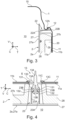
- Fig. 4
- schematically illustrates attachment of a cover in its central region to the rear wall of the container of a refrigerating apparatus in accordance with an embodiment of the invention.
- Fig. 5
- illustrates attachment of a cover in its lower peripheral region to the rear wall of the container of a refrigerating apparatus in accordance with an embodiment of the invention.
- Fig. 6
- schematically illustrates a flow chart of a method for assembling a refrigerating apparatus in accordance with an embodiment of the invention.
- Fig. 7
- schematically illustrates a step of the method for assembling the refrigerating apparatus in accordance with an embodiment of the invention.
- Fig. 8
- schematically illustrates the same step of the method shown in
Fig. 7 in accordance with another embodiment of the invention. - The drawings illustrate the embodiments of the present invention and together with the description serve to explain the principles of the invention. Like reference numerals designate corresponding similar parts.
-
Figs. 1 and 2 exemplarily shows arefrigerating apparatus 100 in the form of a domestic refrigerator. It should be understood the invention is not limited to refrigerators but may also be employed in freezers or similar. As visible fromFigs. 1 and 2 , the refrigeratingapparatus 100 includes acontainer 1, acover 2, and anoptional housing 3. Further, the refrigeratingapparatus 100 comprises a coolant circuit of which only anevaporator 4 is shown inFig. 2 . - The
container 1 defines astorage compartment 10 for receiving items to be cooled such as food, beverages, medicine or similar items. Thecontainer 1 includes arear wall 11 extending in a vertical direction V and limiting the storage compartment with respect to a depth direction T that extends transverse to the vertical direction V. Further, thecontainer 1 includes a bottom 14 and aceiling 15, both extending in the depth direction T and limiting thestorage compartment 10 with respect to the vertical direction V. Additionally,first sidewall 16 andsecond side wall 17 extend in the vertical direction V between the bottom 14 and theceiling 15 and limit thestorage compartment 10 with respect to a transverse direction C. Thecontainer 1, i.e. its walls[KI(1], may be formed from a plastic material, e.g. in a molding process, or from a metal material, e.g. in a deep drawing process. - The
cover 2 has an areal expanse. As shown inFig. 1 , thecover 2 may have a substantially rectangular perimeter or circumference. As schematically shown inFig. 2 , thecover 2 may substantially be plate shaped. In particular, thecover 2 may include acover member 27 and an insulatingmember 28. Thecover member 27 may be in the form of a plate having a first surface of thecover member 27a and a second surface of thecover member 27b. For example, thecover member 27 may be made of a plastic material. A thickness of thecover member 27, measured between a first surface of thecover member 27a and a second surface of thecover member 27b, may be in a range between 0.8 mm and 2.5 mm. The insulatingmember 28 may be made of a thermally insulating material, e.g. of expanded polystyrol (EPS). The insulatingmember 28 is fixed, e.g. bonded, to the second surface of thecover member 27b. - As is schematically shown in
Fig. 2 , thecover 2 is arranged on therear wall 11 and, as will be explained in more detail below, is attached to therear wall 11. As visible fromFig. 2 , the insulatingmember 28 faces an inner surface of therear wall 11a, and thecover member 27 faces thestorage compartment 10. The first surface of thecover member 27a forms a first surface of thecover 2a oriented towards thestorage compartment 10. A second surface of thecover 2b oriented towards the inner surface of therear wall 11a is partially formed by a surface of the insulatingmember 28 and by the second surface of thecover member 27b. As schematically shown inFig. 2 , achannel 20 is defined between the insulatingmember 28 and therear wall 11. Additionally or alternatively, achannel 20 may be defined between thecover member 27 and therear wall 11. Of course more than onechannel 20 may be provided. Thechannels 20 are in fluid communication with thestorage compartment 10 and are provided for directing an air flow to a perimeter of thecover 2. For example, as shown inFig. 1 , thecover 2 may extend in the transverse direction C between the opposingsidewalls respective sidewall cover 2. Through this gap, air may be discharged from thechannels 20 into thestorage compartment 10. - The
cover 2 is positioned on therear wall 11 such that first or long sides of the rectangular perimeter extend in the vertical direction V and second or short sides of the rectangular perimeter extend in the transverse direction C. - The
cover 2 is attached to therear wall 11 at multiple sites along its perimeter. As is only symbolically illustrated inFig. 1 , therear wall 11 and thecover 2 may be fixed to each other via multiplefirst plug structures 12 andsecond plug structures 22 along the perimeter of therear wall 11 and thecover 2. Optionally, central regions of therear wall 11 and thecover 2 may be coupled bythird plug structures 13 andfourth plug structures 23. As exemplarily shown inFig. 1 , threesecond plug structures 22 may be arranged on each first side of thecover 2, and on the second side of thecover 2 adjacent to theceiling 15, twosecond plug structures 22 may be provided. A lower end region of thecover 2 facing the bottom 14 may be attached to therear wall 11 by means of thehousing 3 as will be explained in more detail below. Generally, at least twosecond plug structures 22 may arranged on each first side, and at least onesecond plug structure 22 may arranged on one, preferably on only one of the second sides. Further,Fig. 2 exemplarily shows twofourth plug structures 23 arranged in the central region of thecover 2. However, only one or more than twofourth plug structures 23 may be provided. -
Fig. 3 schematically illustrates attachment of thecover 2 in its vertically upper peripheral region to therear wall 11. Generally, allfirst plug structures 12 andsecond plug structures 22 may be formed identically. Therefore,Fig. 3 is representative for allfirst plug structures 12 andsecond plug structures 22. Thefirst plug structures 12 are formed on the inner surface of therear wall 11a along a perimeter of therear wall 11. As exemplarily shown inFig. 3 , eachfirst plug structure 12 may be formed by a recess of the inner surface of therear wall 11a, wherein said recess defines an undercut 12A with respect to the depth direction T. Thesecond plug structures 22 are integrally formed with thecover 2, in particular, with the second surface of thecover member 27b. Generally, multiplesecond plug structures 22 are formed integrally with thecover 2 on the side of the second surface of thecover 2b along the perimeter of thecover 2. As exemplarily shown inFig. 3 , thesecond plug structures 22 may be formed by elastic hooks, wherein each hook is configured to snap into one of theundercuts 12A. The hooks may, for example, include an elasticsecond shaft 22A protruding from second surface of thecover member 27b, and afirst hook portion 22B protruding laterally from thesecond shaft 22A. Thefirst hook portion 22B, as shown inFig. 3 , engages or protrudes into the undercut 12A of the recess. For connecting the hook and the recess, thecover 2 as a hole can be moved towards therear wall 11 in a linear direction of movement DM, as shown inFig. 7 , or along a curved trajectory as direction of movement DM, as shown inFig. 8 . In both cases, the hook snaps together with the recess and thereby attaches thecover 2 in a form fitting fashion to therear wall 11. - The
first plug structure 12 is not limited to a recess, and thesecond plug structure 22 is not limited to a hook. Generally, each of thefirst plug structures 12 is configured for being positively connected to one of thesecond plug structures 22 by engaging thefirst plug structure 12 andsecond plug structures 22 in the depth direction T. -
Fig. 4 exemplarily shows attachment of thecover 2 in its central region to therear wall 11 of thecontainer 1. Thethird plug structure 13 is arranged in a central region of therear wall 11 on the inner surface of therear wall 11a. For example, thethird plug structure 13 may protrude from the inner surface of therear wall 11a along the depth direction T, as exemplarily shown inFig. 4 . As shown inFig. 4 , thethird plug structure 13 may include afirst shaft 13A protruding from the inner surface of therear wall 11a and ahead 13B positioned on an end of thefirst shaft 13A facing away from the inner surface of therear wall 11a. Thefirst shaft 13A may, for example, be split into twosecond pins 131 that are elastically deformable so as to be able to approach each other. Thehead 13B, generally, has a diameter larger than thefirst shaft 13A so that thehead 13B laterally protrudes from thefirst shaft 13A. As shown inFig. 4 , for example, onethird hook portion 132 may by formed on the end of eachsecond pin 131, wherein thethird hook portions 132 together form thehead 13B. -
Fig. 4 , by way of example only, shows athird plug structure 13 which is formed as a part separate from therear wall 11. However, the invention is not limited thereto. As shown inFig. 4 , thethird plug structure 13 may include aplate 133 from which thefirst shaft 13A protrudes, wherein theplate 133 is positioned on the inner surface of therear wall 11a and covers anopening 11C formed in therear wall 11. Asealing 13C may be formed on the circumference of theplate 133, wherein the sealing 13C extends through theopening 11D and contacts an outer surface of therear wall 11b in a region surrounding theopening 11C. As shown inFig. 4 , thesealing 13C may have a collar that extends through theopening 11C and a lip that laterally extends from the collar and contacts the outer surface of therear wall 11b. The outer surface of therear wall 11b may be covered by an insulatingfoam 6. The sealing 13C prevents that thefoam 6 enters through theopening 11C of the rear wall. Further, the foam rigidly attaches thethird plug structure 13 to the rear wall. Optionally, athird pin 134 may protrude from theplate 133 on a side opposite to thefirst shaft 13A into thefoam material 6. Thereby, thethird plug structure 13 is even more reliably held in position. - The
fourth plug structure 23 may be integrally formed with the second surface of thecover member 27b, as exemplarily shown inFig. 4 . As further shown inFig. 4 , thefourth plug structure 23 may include opposing elastic hooks configured to snap about and engage thehead 13B of thethird plug structure 13. Similar to the second plug structures, the hooks forming thethird plug structure 13, for example, each may have an elasticthird shaft 23A and asecond hook portion 23B protruding laterally from thethird shaft 23A towards the respective otherthird shaft 23A. Thesecond hook portions 23B engage, i.e. clamp about thehead 13B, namely thethird hook portions 132 of thethird plug structure 13. When the cover2 is moved along the depth direction T towards therear wall 11, thethird hook portions 132 of thethird plug structure 13 and thesecond hook portions 23B of thefourth plug structure 23 slide on each other so that thethird shafts 23A orsecond pins 131 elastically deform. When thesecond hook portions 23B of thefourth plug structure 23 are moved beyond thethird hook portions 132 of thethird plug structure 13, thesecond hook portion 23B and third hook portions 132snap in and positively engage. - The
third plug structures 13 andfourth plug structures 23 are not limited to the configuration described above. Generally, thethird plug structure 13 is configured for being positively connected to thefourth plug structure 23 by engaging thethird plug structures 13 andfourth plug structures 23 in the depth direction T. -
Fig. 5 illustrates attachment of thecover 2 in its vertically lower peripheral region to therear wall 11 of thecontainer 1. As shown inFig. 5 , thecover 2, in its lower end region, may be attached to therear wall 11 by means of thehousing 3. - The
housing 3, generally, is arranged on therear wall 11 of thecontainer 1 in a lower end portion of therear wall 11 that faces the bottom 14. Thehousing 3 is attached or fixed to thecontainer 1. For example, snap fit connectors (not shown) may be used to attach thehousing 3 to thecontainer 1. As visible, for example, inFig. 2 , thehousing 3, together with the lower end portion of therear wall 11, defines anevaporator chamber 33, in which theevaporator 4 is accommodated. Theevaporator chamber 33 is in fluid communication with thestorage compartment 10, for example, through anintake opening 31, and with thechannels 20, e.g. via anexhaust opening 32. Air may be conveyed through theevaporator chamber 33 by afan 5. For example, thefan 5 may suck air from thestorage compartment 10 into theevaporator chamber 33 where the coolant flowing in theevaporator 4 draws heat from the air. Thefan 5 further may discharge the air into thechannels 20 from which it is exhausted again into thestorage compartment 10. - As shown in
Fig. 5 , an upper end region of thehousing 3, with respect to the vertical direction V, may overlap the lower end region of thecover 2. Thecover member 27, in the lower end region, may be formed to define multiple steps, to define arecess 25 on its first surface of thecover member 27a and a correspondingprotrusion 26 on its second surface of thecover member 27b, as exemplarily shown inFig. 5 . Generally, thecover 2 may have at least onerecess 25 formed in its first surface of thecover 2a arranged in a lower end region with respect to the vertical direction V. Likewise, therecess 25 of thecover 2 may optionally define aprotrusion 26 on the second surface of thecover 2b. As shown inFig. 5 , thehousing 3 may comprise afirst pin 30 in its upper end region, wherein thefirst pin 30 protrudes into therecess 25 of the cover. - As is further shown in
Fig. 5 , therear wall 11 may include apocket 11D formed in its inner surface of therear wall 11a, wherein theoptional protrusion 26 of thecover 2 protrudes into thepocket 11D of therear wall 11. -
Fig. 6 shows a flow chart of a method M for assembling the refrigeratingapparatus 100. In a first step, in other words positioning M1, thecover 2 is positioned in the storage compartment so that eachsecond plug structure 22 of thecover 2 faces onefirst plug structure 12 of therear wall 11 of thecontainer 1. - In a further step in other word snapping together M2, the
first plug structure 12 andsecond plug structure 22 are engaged or snapped together to fix thecover 2 to therear wall 11. To engage thefirst plug structure 12 andsecond plug structure 22, thecover 2 is moved towards therear wall 11 along the depth direction T. This step of snapping together M2 may include linearly moving thecover 2 in the depth direction, as indicated inFig. 6 by arrow of direction of movement DM indicating a linear path or direction of movement of thecover 2. As a result of this movement, thesecond plug structures 22, e.g. the hooks, approach and engage thefirst plug structures 12, e.g. the recesses with theundercuts 12A. By linearly moving thecover 2, allfirst plug structure 12 andsecond plug structures 22 may be engaged at substantially simultaneously. - Alternatively, the
cover 2 may be moved in step of snapping together M2 along a curved trajectory having a directional component parallel to the depth direction T. As shown inFig. 2 , this movement may be a rotational movement about an axis of rotation AR extending in the transverse direction C. Thereby, thesecond plug structures 22 adjacent to the axis of rotation AR are introduced smoothly into the respectivefirst plug structures 12. - In both alternatives, the direction of movement is along the depth direction t, and the path of movement is continuous without changes in the direction. Thereby, the
cover 2 can be attached to therear wall 11 easily in an automated process, e.g. carried out by a robot or similar. - Step of snapping together M2, further, may include engaging or snapping together the
third plug structures 13 and thefourth plug structures 23 by moving thecover 2 towards therear wall 11 along the depth direction T as described above. - Although specific embodiments have been illustrated and described herein, it will be appreciated by those of ordinary skill in the art that a variety of alternate and/or equivalent implementations may be substituted for the specific embodiments shown and described without departing from the scope of the present invention. Generally, this application is intended to cover any adaptations or variations of the specific embodiments discussed herein.
-
- 1 container
- 2 cover
- 2a first surface of the cover
- 2b second surface of the cover
- 3 housing
- 4 evaporator
- 5 fan
- 6 foam material
- 10 storage compartment
- 11 rear wall
- 11a inner surface of the rear wall
- 11b outer surface of the rear wall
- 11C opening
- 11D pocket
- 12 first plug structure
- 12A undercut
- 13 third plug structure
- 13A first shaft
- 13B head
- 13C sealing
- 14 bottom
- 15 ceiling
- 16 first sidewall
- 17 second side wall
- 20 channel
- 22 second plug structure
- 22A second shaft
- 22B first hook portion
- 23 fourth plug structure
- 23A third shaft
- 23B second hook portion
- 25 recess
- 26 protrusion
- 27 cover member
- 27a first surface of the cover member
- 27b second surface of the cover member
- 28 insulating member
- 30 first pin
- 31 intake opening
- 32 exhaust opening
- 33 evaporator chamber
- 100 refrigerating apparatus
- 131 second pins
- 132 third hook portions
- 133 plate
- 134 third pin
- AR axis of rotation
- C transverse direction
- DM direction of movement
- M method
- M1 positioning
- M2 snapping together
- T depth direction
- V vertical direction
Claims (15)
- A refrigerating apparatus (100), in particular, a domestic refrigerating apparatus, comprising:a container (1) that defines a storage compartment (10) for receiving items to be cooled, the container (1) including a rear wall (11) which has an inner surface of the rear wall (11a) facing the storage compartment (10), wherein multiple first plug structures (12) are formed on the inner surface of the rear wall (11a) along a perimeter of the rear wall (11); anda cover (2) having a first surface of the cover (2a) that faces the storage compartment (10), and an opposite second surface of the cover (2b) that faces the inner surface of the rear wall (11a) of the rear wall (11), wherein channels (20) for directing an air flow to a perimeter of the cover (2) are defined between the cover (2) and the rear wall (11);characterized in thatmultiple second plug structures (22) are formed integrally with the cover (2) on the side of the second surface of the cover (2b) along the perimeter of the cover (2), andeach of the first plug structures (12) is configured for being positively connected to one of the second plug structures (22) by engaging the first plug structures (12) and second plug structures (22) in a depth direction (T) that extends transverse to the rear wall (11).
- The refrigerating apparatus (100) of claim 1, wherein the first plug structures (12) are formed by recesses of the inner surface of the rear wall (11a), each recess defining an undercut (12A) with respect to the depth direction (T), and wherein the second plug structures (22) are formed by elastic hooks, each hook being configured to snap into one of the undercuts (12A).
- The refrigerating apparatus (100) of claim 1 or 2, wherein a third plug structure (13) is arranged in a central region of the rear wall (11) on its inner surface of the rear wall (11a), wherein a fourth plug structure (23) is integrally formed with the cover (2) and positioned on the side of the second surface of the cover (2b) in a central region of the cover (2), and wherein the third plug structure (13) is configured for being positively connected to the fourth plug structure (23) by engaging the third plug structures (13) and fourth plug structures (23) in the depth direction (T).
- The refrigerating apparatus (100) of claim 3, wherein the third plug structure (13) includes a first shaft (13A) protruding from the inner surface of the rear wall (11a) and a head (13B) positioned on an end of the first shaft (13A) facing away from the inner surface of the rear wall (11a), and wherein the fourth plug structure (23) includes opposing elastic hooks configured to snap about and engage the head (13B).
- The refrigerating apparatus (100) of claim 3 or 4, wherein the third plug structure (13) is formed separate from the rear wall (11) and positioned in an opening (11C) of the rear wall (11).
- The refrigerating apparatus (100) of claim 5, wherein the third plug structure (13) includes a sealing (13C) that contacts an outer surface of the rear wall (11b) in a region surrounding the opening (11C), wherein the outer surface of the rear wall (11b) is covered by an insulating foam (6).
- The refrigerating apparatus (100) of any one of the preceding claims, wherein the cover (2) has a substantially rectangular perimeter, with first sides extending along a vertical direction (V) and second sides extending along a transverse direction (C), wherein at least two second plug structures (22) are arranged on each first side, and wherein at least one second plug structure (22) is arranged on one, preferably on only one of the second sides.
- The refrigerating apparatus (100) of any one of the preceding claims, further comprising:a housing (3) arranged on the rear wall (11) of the container (1), the housing (3) including at least one first pin (30) that is arranged in an upper end region of the housing (3);wherein the cover (2) extends in a vertical direction (V), which is transverse to the depth direction (T), and has at least one recess (25) formed in its first surface of the cover (2a) arranged in a lower end region with respect to the vertical direction (V),wherein the upper end region of the housing (3) overlaps the lower end region of the cover (2), and the first pin (30) of the housing (3) engages the recess (25) of the cover (2), andwherein the housing (3) is fixed to the container (1).
- The refrigerating apparatus (100) of claim 8, wherein the rear wall (11) of the container (1) includes a pocket (11D) formed in its inner surface of the rear wall (11a), wherein the recess (25) of the cover (2) defines a protrusion (26) on the second surface of the cover (2b), wherein the protrusion (26) protrudes into the pocket (11D) of the rear wall (11).
- The refrigerating apparatus (100) of claim 8 or 9, wherein the housing (3) together with a lower portion of the rear wall (11) defines an evaporator chamber (33) in which an evaporator (4) is accommodated.
- The refrigerating apparatus (100) of claim 10, wherein the evaporator chamber (33) is in fluid communication with the channels defined on the second surface of the cover (2b).
- The refrigerating apparatus (100) of any one of the preceding claims, wherein the cover (2) includes a cover member (27) facing the storage compartment (10), and an insulating member (28) arranged between the inner surface of the rear wall (11a) and the cover member (27), wherein the channels (20) are defined between the cover member (27) and the inner surface of the rear wall (11a) and/or between the insulating member (28) and the inner surface of the rear wall (11a).
- The refrigerating apparatus (100) of claim 12, wherein the cover member (27) is made of a plastic material and has a thickness in a range between 0.8 mm and 2.5 mm.
- The refrigerating apparatus (100) of claim 12 or 13, wherein the second plug structures (22) are integrally formed with the cover member (27).
- A method (M) for assembling the refrigerating apparatus of any one of the preceding claims, the method (M) comprising:positioning (M1) the cover (2) in the storage compartment (10) defined by the container (1) so that each second plug structure (22) of the cover faces one first plug structure (12) of the rear wall (11) of the container (1); andsnapping together (M2) the first plug structures (12) and the second plug structures (22) to fix the cover (2) to the rear wall (11) by moving the cover (2) towards the rear wall (11) along the depth direction (T), e.g. linearly in the depth direction or along a curved trajectory having a directional component parallel to the depth direction.
Applications Claiming Priority (1)
| Application Number | Priority Date | Filing Date | Title |
|---|---|---|---|
| TR202311174 | 2023-09-08 |
Publications (1)
| Publication Number | Publication Date |
|---|---|
| EP4521042A1 true EP4521042A1 (en) | 2025-03-12 |
Family
ID=92542874
Family Applications (1)
| Application Number | Title | Priority Date | Filing Date |
|---|---|---|---|
| EP24196350.3A Pending EP4521042A1 (en) | 2023-09-08 | 2024-08-26 | Refrigerating apparatus and method for assembling a refrigerating apparatus |
Country Status (1)
| Country | Link |
|---|---|
| EP (1) | EP4521042A1 (en) |
Citations (7)
| Publication number | Priority date | Publication date | Assignee | Title |
|---|---|---|---|---|
| JP2013164259A (en) * | 2013-05-28 | 2013-08-22 | Panasonic Corp | Refrigerator |
| CN204176999U (en) * | 2014-10-10 | 2015-02-25 | 合肥美的电冰箱有限公司 | Wind cooling refrigerator |
| US20180164021A1 (en) * | 2016-12-09 | 2018-06-14 | Bsh Hausgeraete Gmbh | Household refrigerator with specific cover system in a receiving space for food |
| EP2691712B1 (en) * | 2011-03-28 | 2019-08-21 | BSH Hausgeräte GmbH | Refrigerator having an integrally formed air channel |
| WO2019233760A1 (en) | 2018-06-06 | 2019-12-12 | V-Zug Ag | Refrigeration appliance with active air circulation |
| EP3262357B1 (en) * | 2015-02-23 | 2020-03-11 | BSH Hausgeräte GmbH | Cooling device |
| DE102020203080A1 (en) | 2020-03-11 | 2021-09-16 | BSH Hausgeräte GmbH | Refrigeration device with air distributor |
-
2024
- 2024-08-26 EP EP24196350.3A patent/EP4521042A1/en active Pending
Patent Citations (8)
| Publication number | Priority date | Publication date | Assignee | Title |
|---|---|---|---|---|
| EP2691712B1 (en) * | 2011-03-28 | 2019-08-21 | BSH Hausgeräte GmbH | Refrigerator having an integrally formed air channel |
| JP2013164259A (en) * | 2013-05-28 | 2013-08-22 | Panasonic Corp | Refrigerator |
| CN204176999U (en) * | 2014-10-10 | 2015-02-25 | 合肥美的电冰箱有限公司 | Wind cooling refrigerator |
| EP3262357B1 (en) * | 2015-02-23 | 2020-03-11 | BSH Hausgeräte GmbH | Cooling device |
| US20180164021A1 (en) * | 2016-12-09 | 2018-06-14 | Bsh Hausgeraete Gmbh | Household refrigerator with specific cover system in a receiving space for food |
| WO2019233760A1 (en) | 2018-06-06 | 2019-12-12 | V-Zug Ag | Refrigeration appliance with active air circulation |
| DE102020203080A1 (en) | 2020-03-11 | 2021-09-16 | BSH Hausgeräte GmbH | Refrigeration device with air distributor |
| US20230137690A1 (en) * | 2020-03-11 | 2023-05-04 | BSH Hausgeräte GmbH | Refrigeration appliance having an air distributor |
Similar Documents
| Publication | Publication Date | Title |
|---|---|---|
| EP3864355B1 (en) | Refrigerator | |
| US10337774B2 (en) | Refrigeration appliance with an internal evaporator | |
| EP3532781B1 (en) | Skin condenser design integrated in the refrigerator back | |
| US20220042736A1 (en) | Refrigerated compartment air distribution assembly | |
| US20180164029A1 (en) | Household refrigeration appliance with specific mounting of a cover plate to a receiving space for foodstuffs and method of installing a cover plate | |
| CN111902685B (en) | Household appliance with wall with integrated protruding coupling element coupled to a backing member mounted thereon and method of mounting a coupling element on the wall | |
| AU2021343048B2 (en) | Refrigerator | |
| CN105814380A (en) | Domestic refrigeration appliance having a machine room and a ventilator housing mounted on a beam of the machine room and method for installing such a ventilator in the machine room | |
| KR102891179B1 (en) | Refrigerator | |
| JP7136651B2 (en) | refrigerator | |
| TR2023011174A1 (en) | A COOLING APPARATUS AND A METHOD FOR ASSEMBLY OF THE COOLING APPARATUS | |
| US20260126234A1 (en) | Air duct attachment hook system | |
| CN107965966A (en) | No-frost refrigeration device | |
| CN224136167U (en) | refrigerator | |
| EP4040094A1 (en) | Apparatus for producing dairy products, and refrigerator including same | |
| CN223191915U (en) | Refrigerator and vehicle | |
| EP4650692A1 (en) | Refrigerating appliance | |
| EP4495515A1 (en) | Refrigerator | |
| EP4212803B1 (en) | Heat-insulated housing of a household refrigeration appliance | |
| US20250146734A1 (en) | Refrigeration appliance, heat exchanger assembly for a refrigeration appliance, method for mounting a fan in a housing, and method for producing a heat exchanger assembly | |
| CN220959090U (en) | Air duct cover plate assembly and refrigerator | |
| EP4290162A1 (en) | Domestic cooling appliance comprising a reinforcement part | |
| CN120947258A (en) | Refrigeration appliances | |
| EP4417882A1 (en) | Ceiling-type air conditioner | |
| CN210141729U (en) | Refrigerator with a door |
Legal Events
| Date | Code | Title | Description |
|---|---|---|---|
| PUAI | Public reference made under article 153(3) epc to a published international application that has entered the european phase |
Free format text: ORIGINAL CODE: 0009012 |
|
| STAA | Information on the status of an ep patent application or granted ep patent |
Free format text: STATUS: THE APPLICATION HAS BEEN PUBLISHED |
|
| AK | Designated contracting states |
Kind code of ref document: A1 Designated state(s): AL AT BE BG CH CY CZ DE DK EE ES FI FR GB GR HR HU IE IS IT LI LT LU LV MC ME MK MT NL NO PL PT RO RS SE SI SK SM TR |
|
| STAA | Information on the status of an ep patent application or granted ep patent |
Free format text: STATUS: REQUEST FOR EXAMINATION WAS MADE |
|
| 17P | Request for examination filed |
Effective date: 20250912 |