EP4521007A1 - A kind of self-locking mechanism for the manual override - Google Patents
A kind of self-locking mechanism for the manual override Download PDFInfo
- Publication number
- EP4521007A1 EP4521007A1 EP24196430.3A EP24196430A EP4521007A1 EP 4521007 A1 EP4521007 A1 EP 4521007A1 EP 24196430 A EP24196430 A EP 24196430A EP 4521007 A1 EP4521007 A1 EP 4521007A1
- Authority
- EP
- European Patent Office
- Prior art keywords
- locking
- operating member
- valve actuator
- axis
- operating
- Prior art date
- Legal status (The legal status is an assumption and is not a legal conclusion. Google has not performed a legal analysis and makes no representation as to the accuracy of the status listed.)
- Pending
Links
Images





Classifications
-
- F—MECHANICAL ENGINEERING; LIGHTING; HEATING; WEAPONS; BLASTING
- F16—ENGINEERING ELEMENTS AND UNITS; GENERAL MEASURES FOR PRODUCING AND MAINTAINING EFFECTIVE FUNCTIONING OF MACHINES OR INSTALLATIONS; THERMAL INSULATION IN GENERAL
- F16K—VALVES; TAPS; COCKS; ACTUATING-FLOATS; DEVICES FOR VENTING OR AERATING
- F16K35/00—Means to prevent accidental or unauthorised actuation
- F16K35/02—Means to prevent accidental or unauthorised actuation to be locked or disconnected by means of a pushing or pulling action
- F16K35/027—Means to prevent accidental or unauthorised actuation to be locked or disconnected by means of a pushing or pulling action the locking mechanism being actuated by pushing or pulling the valve actuator, the valve actuator being rotated subsequently to bring the valve closure element in the desired position
-
- F—MECHANICAL ENGINEERING; LIGHTING; HEATING; WEAPONS; BLASTING
- F16—ENGINEERING ELEMENTS AND UNITS; GENERAL MEASURES FOR PRODUCING AND MAINTAINING EFFECTIVE FUNCTIONING OF MACHINES OR INSTALLATIONS; THERMAL INSULATION IN GENERAL
- F16K—VALVES; TAPS; COCKS; ACTUATING-FLOATS; DEVICES FOR VENTING OR AERATING
- F16K35/00—Means to prevent accidental or unauthorised actuation
-
- F—MECHANICAL ENGINEERING; LIGHTING; HEATING; WEAPONS; BLASTING
- F16—ENGINEERING ELEMENTS AND UNITS; GENERAL MEASURES FOR PRODUCING AND MAINTAINING EFFECTIVE FUNCTIONING OF MACHINES OR INSTALLATIONS; THERMAL INSULATION IN GENERAL
- F16K—VALVES; TAPS; COCKS; ACTUATING-FLOATS; DEVICES FOR VENTING OR AERATING
- F16K31/00—Actuating devices; Operating means; Releasing devices
- F16K31/44—Mechanical actuating means
- F16K31/60—Handles
-
- F—MECHANICAL ENGINEERING; LIGHTING; HEATING; WEAPONS; BLASTING
- F16—ENGINEERING ELEMENTS AND UNITS; GENERAL MEASURES FOR PRODUCING AND MAINTAINING EFFECTIVE FUNCTIONING OF MACHINES OR INSTALLATIONS; THERMAL INSULATION IN GENERAL
- F16K—VALVES; TAPS; COCKS; ACTUATING-FLOATS; DEVICES FOR VENTING OR AERATING
- F16K35/00—Means to prevent accidental or unauthorised actuation
- F16K35/02—Means to prevent accidental or unauthorised actuation to be locked or disconnected by means of a pushing or pulling action
- F16K35/022—Means to prevent accidental or unauthorised actuation to be locked or disconnected by means of a pushing or pulling action the locking mechanism being actuated by a separate actuating element
-
- F—MECHANICAL ENGINEERING; LIGHTING; HEATING; WEAPONS; BLASTING
- F16—ENGINEERING ELEMENTS AND UNITS; GENERAL MEASURES FOR PRODUCING AND MAINTAINING EFFECTIVE FUNCTIONING OF MACHINES OR INSTALLATIONS; THERMAL INSULATION IN GENERAL
- F16K—VALVES; TAPS; COCKS; ACTUATING-FLOATS; DEVICES FOR VENTING OR AERATING
- F16K35/00—Means to prevent accidental or unauthorised actuation
- F16K35/02—Means to prevent accidental or unauthorised actuation to be locked or disconnected by means of a pushing or pulling action
- F16K35/022—Means to prevent accidental or unauthorised actuation to be locked or disconnected by means of a pushing or pulling action the locking mechanism being actuated by a separate actuating element
- F16K35/025—Means to prevent accidental or unauthorised actuation to be locked or disconnected by means of a pushing or pulling action the locking mechanism being actuated by a separate actuating element said actuating element being operated manually (e.g. a push-button located in the valve actuator)
Definitions
- the present invention relates to the field of valves, and in particular to a valve actuator.
- a valve actuator is a machine for driving a valve.
- the valve actuator is generally provided with a manual operating mechanism.
- the manual operating mechanism is used to manually drive a valve stem of the valve.
- the manual operating mechanism of the existing valve actuator cannot be locked after the operation is completed, and it is difficult to maintain the valve stem in a fixed position.
- An objective of the present invention is to provide a valve actuator, of which a manual operating mechanism can be locked after operation.
- the present invention provides a valve actuator, which includes a support body, an operating member and a locking member.
- the support body is provided with a plurality of locking structures.
- the plurality of locking structures are distributed in a circumferential direction, with an axis surrounded by the circumferential direction being defined as a first axis.
- the operating member is rotatably connected to the support body about the first axis.
- the locking member is movably connected to the operating member.
- the operating member can rotate relative to the support body to a plurality of locked positions. Each locked position corresponds to one of the locking structures. When the operating member is in the locked position, the locking member can move relative to the operating member to engage with the corresponding locking structure to prevent the operating member from rotating relative to the support body.
- the valve actuator can enable locking and unlocking of the operating member by means of the locking structures and the locking member.
- a movement trajectory of the locking member relative to the operating member is configured to be gradually away from the first axis in the circumferential direction.
- the valve actuator further includes a locking drive member.
- the locking drive member is rotatably connected to the operating member about the first axis. The locking drive member can push the locking member to move relative to the operating member by rotating relative to the operating member. This can facilitate operation.
- the movement trajectory of the locking member relative to the operating member is a straight line trajectory or an arc trajectory perpendicular to the first axis. This makes the overall structure more compact and helps save space.
- the locking drive member is provided with a driving hole extending therethrough in a first direction, the first direction being parallel to the first axis.
- the driving hole extends in a radial direction of rotation of the operating member.
- the locking member passes through the driving hole.
- the locking drive member rotating relative to the operating member can push the locking member to move relative to the operating member by means of a wall of the driving hole.
- the operating member includes a rotating shaft portion.
- the rotating shaft portion is rotatably inserted in the support body about the first axis.
- the locking drive member includes an annular pivoting portion.
- the pivoting portion is rotatably sleeved on the rotating shaft portion.
- an annular groove extending in the circumferential direction is recessed from a surface of the rotating shaft portion.
- An inner edge of the pivoting portion is provided with a plurality of hooks.
- the plurality of hooks are distributed in the circumferential direction and form a snap-fit connection with a wall of the annular groove to prevent the locking drive member from moving relative to the operating member in a direction parallel to the first axis.
- the operating member includes a knob portion.
- a circumferential outer surface of the knob portion is provided with a notch.
- a front end of the locking drive member in a radial direction of rotation of the operating member is provided with an operating portion.
- the operating portion is arranged in the notch. This facilitates operation and can also make the overall structure more compact.
- the locking drive member is provided with a first limiting structure
- the operating member is provided with a second limiting structure.
- One of the first limiting structure and the second limiting structure is a protrusion, and the other thereof is provided with a groove mating with the protrusion.
- the limiting position corresponds to a state where the locking member is engaged with the locking structure or to a state where the locking member is disengaged from the locking structure. In this way, a stuck feeling can be generated when the operating member rotates to the limiting position, and it is helpful to keep the locking drive member in the limiting position.
- the locking structures are slots. When the operating member is located in the locked position, the locking member can move to be inserted into the corresponding slot to prevent the operating member from rotating relative to the support body. Such a structure is easy to manufacture and has a good stability.
- the operating member includes a knob portion.
- the support body has a top face opposite the knob portion in a first direction, the first direction being parallel to the first axis.
- the slots are recessed from a part of the top face that is opposite the knob portion in the first direction.
- the locking member is arranged between the knob portion and the top face in the first direction. This makes the overall structure more compact and helps save space.
- a cross section of the slot perpendicular to an insertion direction of the locking member is in the shape of a triangle with an apex oriented in an opposite direction of the first direction.
- a cross section of an end, which is configured to be inserted into the slot, of the locking member perpendicular to the insertion direction of the locking member is in the shape of a triangle with an apex oriented in the opposite direction of the first direction.
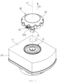
- FIG. 1 is a schematic structural diagram of an exemplary embodiment of a valve actuator.
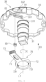
- FIG. 2 is an exploded view of the valve actuator shown in FIG. 1 .
- FIG. 3 is a schematic view of a partial structure of the valve actuator shown in FIG. 1 .
- FIG. 4 is an exploded view of the structure shown in FIG. 3 .
- the valve actuator includes a support body 10, an operating member 30 and a locking member 50.
- the support body 10 is provided with a plurality of locking structures 12.
- FIG. 2 only schematically shows one of the locking structures 12.
- the locking structure 12 is, for example, a slot.
- the plurality of locking structures 12 are distributed in a circumferential direction C, with an axis C surrounded by the circumferential direction being defined as a first axis L1.
- the plurality of locking structures 12 are continuously arranged in a ring shape in the circumferential direction C, but are not limited thereto.
- the number of locking structures 12 may be adjusted as required, or the locking structures may be arranged at intervals.
- the operating member 30 is rotatably connected to the support body 10 about the first axis L1.
- the operating member 30 is configured to be manually operated by an operator to drive a valve stem of the valve to rotate.
- the valve actuator for example, further includes a transmission structure and an electric mechanism.
- the rotating operating member 30 may, for example, drive the valve stem of the valve to rotate by means of the transmission structure, and the electric mechanism may, for example, also drive the valve stem of the valve to rotate by means of the transmission structure.
- the locking member 50 is movably connected to the operating member 30.
- the operating member 30 is provided with a slide groove 331, and the locking member 50 is inserted in the slide groove 331 and can slide in the slide groove 331.
- Such a structure is simple and is easy to manufacture. However, it is not limited to this.
- the locking member 50 may be movably connected to the operating member 30 via other structures.
- the operating member 30 can rotate relative to the support body 10 to a plurality of locked positions. Each locked position corresponds to one of the locking structures 12.
- the locking member 50 can move relative to the operating member 30 to engage with the corresponding locking structure 12 to prevent the operating member 30 from rotating relative to the support body 10.
- FIG. 5 is a schematic view of the structure shown in FIG. 3 in another state. Referring to FIGS 3 and 5 , specifically, when the operating member 30 is in the locked position, the locking member 50 can slide along the slide groove 331 from the position shown in FIG. 5 to the position shown in FIG. 3 , so as to be inserted into the slot of one of the locking structures 12.
- the operating member 30 After insertion, the operating member 30 can be prevented from rotating relative to the support body 10 by the mutual abutment between the locking member 50 and a wall of the slot, and the rotation position of the operating member 30 is locked.
- the locking member 50 slides along the slide groove 331 from the position shown in FIG. 3 to the position shown in FIG. 5 , and the locking member 50 is disengaged from the slot of the locking structure 12, and the operating member 30 is unlocked and can rotate relative to the support body 10.
- the valve actuator of this exemplary embodiment can enable locking and unlocking of the operating member.
- the locking structure 12 is a slot, which is easy to manufacture and has a good stability.
- the locking structure 12 may be other structures than the slot.
- the locking structure 12 is configured as a hole, and the locking member 50 is provided with a pin that can be inserted into the hole.
- the locking structure 12 is configured as a hole, and the locking member 50 is provided with a pin that can be inserted into the hole.
- it is not limited to this.
- a movement trajectory of the locking member 50 relative to the operating member 30 is configured to be gradually away from the first axis L1 in the circumferential direction C.
- the movement trajectory of the locking member 50 relative to the operating member 30 (embodied as an extension trajectory of the slide groove 331) is, but is not limited to, a straight line trajectory perpendicular to the first axis L1.
- the movement trajectory of the locking member 50 relative to the operating member 30 may be an arc trajectory perpendicular to the first axis L1.
- the movement trajectory of the locking member 50 relative to the operating member 30 being perpendicular to the first axis L1 is conducive to saving space. However, it is not limited to this. In other exemplary embodiments, the movement trajectory of the locking member 50 relative to the operating member 30 may not be perpendicular to the first axis L1.
- the valve actuator further includes a locking drive member 70.
- the locking drive member 70 is rotatably connected to the operating member 30 about the first axis L1.
- the locking drive member 70 can push the locking member 50 to move relative to the operating member 30 by rotating relative to the operating member 30.
- the locking drive member 70 is provided with a driving hole 71 extending therethrough in a first direction D1.
- the first direction D1 is parallel to the first axis L1.
- the driving hole 71 extends in a radial direction of rotation of the operating member 30, and the radial direction of rotation of the operating member 30 is a radial direction with the first axis L1 as the axis.
- the locking member 50 passes through the driving hole 71.
- the locking drive member 70 rotating relative to the operating member 30 can push the locking member 50 to move relative to the operating member 30 by means of a wall of the driving hole 71.
- Such a structure is simple, is easy to manufacture and has a good stability.
- the operating member 30 includes a rotating shaft portion 31 and a knob portion 33.
- the rotating shaft portion 31 is rotatably inserted in the support body 10 about the first axis L1.
- the knob portion 33 is located on a front side (i.e., an upper side in FIGS 3 to 5 ) of the rotating shaft portion 31 in the first direction D1 and is fixedly connected to the rotating shaft portion 31.
- the slide groove 331 is recessed in the first direction D1 from a rear end face (i.e., a lower end face in FIGS 3 to 5 ) of the knob portion 33 in the first direction D1.
- the locking member 50 has an upper end inserted in the slide groove 331, and a lower end configured to engage with the locking structure 12 to prevent the operating member 30 from rotating relative to the support body 10.
- the locking drive member 70 is arranged on a rear side (i.e., a lower side in FIGS 3 to 5 ) of the knob portion 33 in the first direction D1. This makes the overall structure more compact and helps save space.
- the locking drive member 70 includes an annular pivoting portion 72.
- the pivoting portion 72 is rotatably sleeved on the rotating shaft portion 31. Such a structure saves space and facilitates assembly.
- an annular groove 311 extending in the circumferential direction C is recessed from a surface of the rotating shaft portion 31.
- An inner edge of the pivoting portion 72 is provided with two hooks 721.
- the two hooks 721 are evenly distributed in the circumferential direction C and form a snap-fit connection with a wall of the annular groove 311 to prevent the locking drive member 70 from moving relative to the operating member 30 in a direction parallel to the first axis L1.
- the rotating shaft portion 31 is inserted into a central hole of the pivoting portion 72 in an opposite direction of the first direction D1 until the hooks 721 form a snap-fit connection with the wall of the annular groove 311, and the assembly of the two is completed.
- the number of hooks 721 may be adjusted as required. Such a structure can facilitate assembly.
- a circumferential outer surface of the knob portion 33 is provided with a notch 332.
- a front end of the locking drive member 70 in a radial direction of rotation of the operating member 30 is provided with an operating portion 73.
- the operating portion 73 is arranged in the notch 332. This facilitates operation and can also make the overall structure more compact.
- the locking drive member 70 is provided with two first limiting structures, and the operating member 30 is provided with two second limiting structures.
- One first limiting structure and one second limiting structure form a limiting group.
- One of the first limiting structure and the second limiting structure is a protrusion 81, and the other thereof is provided with a groove 82 mating with the protrusion 81.
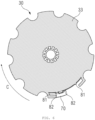
- FIG. 6 is a cross-sectional view along VI-VI in FIG. 3 .
- the protrusion 81 is provided on the knob portion 33
- the groove 82 is provided on the locking drive member 70.
- FIG. 6 it is not limited to this.
- FIG. 6 to FIG. 8 sequentially show three states of the locking drive member 70 rotating in an opposite direction of the circumferential direction C.
- FIG. 6 corresponds to the state shown in FIG. 3 (i.e., corresponding to the state where the locking member 50 is engaged with the locking structure 12)
- FIG. 8 corresponds to the state shown in FIG. 5 (i.e., corresponding to the state where the locking member 50 is disengaged from the locking structure 12).
- the protrusion 81 on the left side is embedded in the groove 82 on the left side to prevent the locking drive member 70 from rotating relative to the operating member 30.
- a wall, against which the protrusion 81 on the left side abuts, of the groove 82 on the left side can be elastically deformed to allow the locking drive member 70 to continue to rotate.
- the protrusion 81 on the right side is embedded in the groove 82 on the right side to prevent the locking drive member 70 from rotating relative to the operating member 30.
- a wall, against which the protrusion 81 on the right side abuts, of the groove 82 on the right side can be elastically deformed to allow the locking drive member 70 to continue to rotate.
- a stuck feeling can be generated when the operating member rotates to the two limiting positions shown in FIG. 6 and FIG. 8 , and it is helpful to keep the locking drive member in the two limiting positions.
- the number of first limiting structures and the number of second limiting structures may be adjusted as required, for example, both are set to one.
- the support body 10 has a top face 11 opposite the knob portion 33 in the first direction D1.
- the slots of the locking structures 12 are recessed from a part of the top face 11 that is opposite the knob portion 33 in the first direction D1.
- the locking member 50 is arranged between the knob portion 33 and the top face 11 in the first direction D1. This makes the overall structure more compact and helps save space.
Landscapes
- Engineering & Computer Science (AREA)
- General Engineering & Computer Science (AREA)
- Mechanical Engineering (AREA)
- Preventing Unauthorised Actuation Of Valves (AREA)
Abstract
A valve actuator includes a support body (10), an operating member (30) and a locking member (50). The support body is provided with a plurality of locking structures (12). The plurality of locking structures are distributed in a circumferential direction (C), with an axis surrounded by the circumferential direction being defined as a first axis (L1). The operating member is rotatably connected to the support body about the first axis. The locking member is movably connected to the operating member. The operating member can rotate relative to the support body to a plurality of locked positions. Each locked position corresponds to one of the locking structures. When the operating member is in the locked position, the locking member can move relative to the operating member to engage with the corresponding locking structure to prevent the operating member from rotating relative to the support body. The valve actuator can enable locking and unlocking of the operating member.
Description
- The present invention relates to the field of valves, and in particular to a valve actuator.
- A valve actuator is a machine for driving a valve. The valve actuator is generally provided with a manual operating mechanism. The manual operating mechanism is used to manually drive a valve stem of the valve. The manual operating mechanism of the existing valve actuator cannot be locked after the operation is completed, and it is difficult to maintain the valve stem in a fixed position.
- An objective of the present invention is to provide a valve actuator, of which a manual operating mechanism can be locked after operation.
- The present invention provides a valve actuator, which includes a support body, an operating member and a locking member. The support body is provided with a plurality of locking structures. The plurality of locking structures are distributed in a circumferential direction, with an axis surrounded by the circumferential direction being defined as a first axis. The operating member is rotatably connected to the support body about the first axis. The locking member is movably connected to the operating member. The operating member can rotate relative to the support body to a plurality of locked positions. Each locked position corresponds to one of the locking structures. When the operating member is in the locked position, the locking member can move relative to the operating member to engage with the corresponding locking structure to prevent the operating member from rotating relative to the support body.
- The valve actuator can enable locking and unlocking of the operating member by means of the locking structures and the locking member.
- In another exemplary embodiment of the valve actuator, a movement trajectory of the locking member relative to the operating member is configured to be gradually away from the first axis in the circumferential direction. The valve actuator further includes a locking drive member. The locking drive member is rotatably connected to the operating member about the first axis. The locking drive member can push the locking member to move relative to the operating member by rotating relative to the operating member. This can facilitate operation.
- In still another exemplary embodiment of the valve actuator, the movement trajectory of the locking member relative to the operating member is a straight line trajectory or an arc trajectory perpendicular to the first axis. This makes the overall structure more compact and helps save space.
- In a further exemplary embodiment of the valve actuator, the locking drive member is provided with a driving hole extending therethrough in a first direction, the first direction being parallel to the first axis. The driving hole extends in a radial direction of rotation of the operating member. The locking member passes through the driving hole. The locking drive member rotating relative to the operating member can push the locking member to move relative to the operating member by means of a wall of the driving hole. Such a structure is simple, is easy to manufacture and has a good stability.
- In a further exemplary embodiment of the valve actuator, the operating member includes a rotating shaft portion and a knob portion. The rotating shaft portion is rotatably inserted in the support body about the first axis. The knob portion is located on a front side of the rotating shaft portion in the first direction and is fixedly connected to the rotating shaft portion. A rear end face of the knob portion in the first direction is provided with a slide groove recessed in the first direction. The locking member is inserted in the slide groove and can slide in the slide groove. The locking drive member is arranged on a rear side of the knob portion in the first direction. This makes the overall structure more compact and helps save space.
- In a further exemplary embodiment of the valve actuator, the operating member includes a rotating shaft portion. The rotating shaft portion is rotatably inserted in the support body about the first axis. The locking drive member includes an annular pivoting portion. The pivoting portion is rotatably sleeved on the rotating shaft portion. Such a structure saves space and facilitates assembly.
- In a further exemplary embodiment of the valve actuator, an annular groove extending in the circumferential direction is recessed from a surface of the rotating shaft portion. An inner edge of the pivoting portion is provided with a plurality of hooks. The plurality of hooks are distributed in the circumferential direction and form a snap-fit connection with a wall of the annular groove to prevent the locking drive member from moving relative to the operating member in a direction parallel to the first axis. Such a structure can facilitate assembly.
- In a further exemplary embodiment of the valve actuator, the operating member includes a knob portion. A circumferential outer surface of the knob portion is provided with a notch. A front end of the locking drive member in a radial direction of rotation of the operating member is provided with an operating portion. The operating portion is arranged in the notch. This facilitates operation and can also make the overall structure more compact.
- In a further exemplary embodiment of the valve actuator, the locking drive member is provided with a first limiting structure, and the operating member is provided with a second limiting structure. One of the first limiting structure and the second limiting structure is a protrusion, and the other thereof is provided with a groove mating with the protrusion. When the locking drive member is located in a limiting position relative to the operating member, the protrusion is embedded in the groove to prevent the locking drive member from rotating relative to the operating member. During rotation of the locking drive member into or out of the limiting position, a wall, against which the protrusion abuts, of the groove can be elastically deformed to allow the locking drive member to continue to rotate. The limiting position corresponds to a state where the locking member is engaged with the locking structure or to a state where the locking member is disengaged from the locking structure. In this way, a stuck feeling can be generated when the operating member rotates to the limiting position, and it is helpful to keep the locking drive member in the limiting position.
- In a further exemplary embodiment of the valve actuator, the locking structures are slots. When the operating member is located in the locked position, the locking member can move to be inserted into the corresponding slot to prevent the operating member from rotating relative to the support body. Such a structure is easy to manufacture and has a good stability.
- In a further exemplary embodiment of the valve actuator, the operating member includes a knob portion. The support body has a top face opposite the knob portion in a first direction, the first direction being parallel to the first axis. The slots are recessed from a part of the top face that is opposite the knob portion in the first direction. The locking member is arranged between the knob portion and the top face in the first direction. This makes the overall structure more compact and helps save space.
- In a further exemplary embodiment of the valve actuator, a cross section of the slot perpendicular to an insertion direction of the locking member is in the shape of a triangle with an apex oriented in an opposite direction of the first direction. A cross section of an end, which is configured to be inserted into the slot, of the locking member perpendicular to the insertion direction of the locking member is in the shape of a triangle with an apex oriented in the opposite direction of the first direction. Such a structure has a good stability and can also facilitate the arrangement of a larger number of slots, thereby improving the accuracy of manual control of the valve actuator.
- The following accompanying drawings merely illustratively describe and explain the present invention and do not limit the scope of the present invention.
-
FIG. 1 is a schematic structural diagram of an exemplary embodiment of a valve actuator. -
FIG. 2 is an exploded view of the valve actuator shown inFIG. 1 . -
FIG. 3 is a schematic view of a partial structure of the valve actuator shown inFIG. 1 . -
FIG. 4 is an exploded view of the structure shown inFIG. 3 . -
FIG. 5 is a schematic view of the structure shown inFIG. 3 in another state. -
FIGS 6 to 8 illustrate a mating relationship between a protrusion and a groove when a locking drive member is in different rotation positions. - Description of reference signs:
- 10 support body
- 11 top face
- 12 locking structure
- 30 operating member
- 31 rotating shaft portion
- 311 annular groove
- 33 knob portion
- 331 slide groove
- 332 notch
- 50 locking member
- 70 locking drive member
- 71 driving hole
- 72 pivoting portion
- 721 hook
- 73 operating portion
- 81 protrusion
- 82 groove
- C circumferential direction
- L1 first axis
- D1 first direction
- For the sake of better understanding of the technical features, objects and effects of the present invention, particular embodiments of the present invention will now be described by reference to the accompanying drawings, and in the drawings like numerals refer to components with the same structure or with similar structure but the same function.
- The term "exemplary" herein means "serving as an example, instance or description", and any "exemplary" illustration and embodiment herein should not be interpreted as a more preferred or a more advantageous technical solution.
- The terms "first", "second", etc. herein do not indicate their importance or order, etc., but are only used to indicate the differences between them for the convenience of description of the document.
- For clarity of the drawings, only the relevant parts of the present invention are schematically shown throughout the drawings, but they do not represent the actual structure of a product.
-
FIG. 1 is a schematic structural diagram of an exemplary embodiment of a valve actuator.FIG. 2 is an exploded view of the valve actuator shown inFIG. 1 .FIG. 3 is a schematic view of a partial structure of the valve actuator shown inFIG. 1 .FIG. 4 is an exploded view of the structure shown inFIG. 3 . As shown inFIGS 1 to 4 , the valve actuator includes asupport body 10, an operatingmember 30 and a lockingmember 50. - As shown in
FIG. 2 , thesupport body 10 is provided with a plurality of lockingstructures 12.FIG. 2 only schematically shows one of the lockingstructures 12. In this exemplary embodiment, the lockingstructure 12 is, for example, a slot. The plurality of lockingstructures 12 are distributed in a circumferential direction C, with an axis C surrounded by the circumferential direction being defined as a first axis L1. In this exemplary embodiment, the plurality of lockingstructures 12 are continuously arranged in a ring shape in the circumferential direction C, but are not limited thereto. In other exemplary embodiments, the number of lockingstructures 12 may be adjusted as required, or the locking structures may be arranged at intervals. - As shown in
FIGS 1 and2 , the operatingmember 30 is rotatably connected to thesupport body 10 about the first axis L1. The operatingmember 30 is configured to be manually operated by an operator to drive a valve stem of the valve to rotate. The valve actuator, for example, further includes a transmission structure and an electric mechanism. Therotating operating member 30 may, for example, drive the valve stem of the valve to rotate by means of the transmission structure, and the electric mechanism may, for example, also drive the valve stem of the valve to rotate by means of the transmission structure. - The locking
member 50 is movably connected to the operatingmember 30. Specifically, as shown inFIGS 3 and4 , the operatingmember 30 is provided with aslide groove 331, and the lockingmember 50 is inserted in theslide groove 331 and can slide in theslide groove 331. Such a structure is simple and is easy to manufacture. However, it is not limited to this. In other exemplary embodiments, the lockingmember 50 may be movably connected to the operatingmember 30 via other structures. - The operating
member 30 can rotate relative to thesupport body 10 to a plurality of locked positions. Each locked position corresponds to one of the lockingstructures 12. When the operatingmember 30 is in the locked position, the lockingmember 50 can move relative to the operatingmember 30 to engage with the corresponding lockingstructure 12 to prevent the operatingmember 30 from rotating relative to thesupport body 10.FIG. 5 is a schematic view of the structure shown inFIG. 3 in another state. Referring toFIGS 3 and5 , specifically, when the operatingmember 30 is in the locked position, the lockingmember 50 can slide along theslide groove 331 from the position shown inFIG. 5 to the position shown inFIG. 3 , so as to be inserted into the slot of one of the lockingstructures 12. After insertion, the operatingmember 30 can be prevented from rotating relative to thesupport body 10 by the mutual abutment between the lockingmember 50 and a wall of the slot, and the rotation position of the operatingmember 30 is locked. When the operatingmember 30 needs to be rotated, the lockingmember 50 slides along theslide groove 331 from the position shown inFIG. 3 to the position shown inFIG. 5 , and the lockingmember 50 is disengaged from the slot of the lockingstructure 12, and the operatingmember 30 is unlocked and can rotate relative to thesupport body 10. The valve actuator of this exemplary embodiment can enable locking and unlocking of the operating member. - In this exemplary embodiment, the locking
structure 12 is a slot, which is easy to manufacture and has a good stability. In other exemplary embodiments, the lockingstructure 12 may be other structures than the slot. For example, the lockingstructure 12 is configured as a hole, and the lockingmember 50 is provided with a pin that can be inserted into the hole. However, it is not limited to this. - In an exemplary embodiment, a movement trajectory of the locking
member 50 relative to the operatingmember 30 is configured to be gradually away from the first axis L1 in the circumferential direction C. Specifically, as shown inFIG. 4 , in this exemplary embodiment, the movement trajectory of the lockingmember 50 relative to the operating member 30 (embodied as an extension trajectory of the slide groove 331) is, but is not limited to, a straight line trajectory perpendicular to the first axis L1. In other exemplary embodiments, the movement trajectory of the lockingmember 50 relative to the operatingmember 30 may be an arc trajectory perpendicular to the first axis L1. The movement trajectory of the lockingmember 50 relative to the operatingmember 30 being perpendicular to the first axis L1 is conducive to saving space. However, it is not limited to this. In other exemplary embodiments, the movement trajectory of the lockingmember 50 relative to the operatingmember 30 may not be perpendicular to the first axis L1. - As shown in
FIGS 3 to 5 , the valve actuator further includes a lockingdrive member 70. The lockingdrive member 70 is rotatably connected to the operatingmember 30 about the first axis L1. The lockingdrive member 70 can push the lockingmember 50 to move relative to the operatingmember 30 by rotating relative to the operatingmember 30. Specifically, the lockingdrive member 70 is provided with a drivinghole 71 extending therethrough in a first direction D1. The first direction D1 is parallel to the first axis L1. The drivinghole 71 extends in a radial direction of rotation of the operatingmember 30, and the radial direction of rotation of the operatingmember 30 is a radial direction with the first axis L1 as the axis. The lockingmember 50 passes through the drivinghole 71. The lockingdrive member 70 rotating relative to the operatingmember 30 can push the lockingmember 50 to move relative to the operatingmember 30 by means of a wall of the drivinghole 71. Such a structure is simple, is easy to manufacture and has a good stability. - As shown in
FIGS 3 to 5 , in an exemplary embodiment, the operatingmember 30 includes arotating shaft portion 31 and aknob portion 33. Therotating shaft portion 31 is rotatably inserted in thesupport body 10 about the first axis L1. Theknob portion 33 is located on a front side (i.e., an upper side inFIGS 3 to 5 ) of therotating shaft portion 31 in the first direction D1 and is fixedly connected to therotating shaft portion 31. Theslide groove 331 is recessed in the first direction D1 from a rear end face (i.e., a lower end face inFIGS 3 to 5 ) of theknob portion 33 in the first direction D1. The lockingmember 50 has an upper end inserted in theslide groove 331, and a lower end configured to engage with the lockingstructure 12 to prevent the operatingmember 30 from rotating relative to thesupport body 10. The lockingdrive member 70 is arranged on a rear side (i.e., a lower side inFIGS 3 to 5 ) of theknob portion 33 in the first direction D1. This makes the overall structure more compact and helps save space. - As shown in
FIGS 3 to 5 , in an exemplary embodiment, the lockingdrive member 70 includes anannular pivoting portion 72. The pivotingportion 72 is rotatably sleeved on therotating shaft portion 31. Such a structure saves space and facilitates assembly. - As shown in
FIG. 4 , in an exemplary embodiment, anannular groove 311 extending in the circumferential direction C is recessed from a surface of therotating shaft portion 31. An inner edge of the pivotingportion 72 is provided with twohooks 721. The twohooks 721 are evenly distributed in the circumferential direction C and form a snap-fit connection with a wall of theannular groove 311 to prevent thelocking drive member 70 from moving relative to the operatingmember 30 in a direction parallel to the first axis L1. During assembly, therotating shaft portion 31 is inserted into a central hole of the pivotingportion 72 in an opposite direction of the first direction D1 until thehooks 721 form a snap-fit connection with the wall of theannular groove 311, and the assembly of the two is completed. In other exemplary embodiments, the number ofhooks 721 may be adjusted as required. Such a structure can facilitate assembly. - As shown in
FIGS 1 to 3 , in an exemplary embodiment, a circumferential outer surface of theknob portion 33 is provided with anotch 332. A front end of the lockingdrive member 70 in a radial direction of rotation of the operatingmember 30 is provided with an operatingportion 73. The operatingportion 73 is arranged in thenotch 332. This facilitates operation and can also make the overall structure more compact. - In an exemplary embodiment, the locking
drive member 70 is provided with two first limiting structures, and the operatingmember 30 is provided with two second limiting structures. One first limiting structure and one second limiting structure form a limiting group. One of the first limiting structure and the second limiting structure is aprotrusion 81, and the other thereof is provided with agroove 82 mating with theprotrusion 81.FIG. 6 is a cross-sectional view along VI-VI inFIG. 3 . As shown inFIG. 6 , in this exemplary embodiment, theprotrusion 81 is provided on theknob portion 33, and thegroove 82 is provided on the lockingdrive member 70. However, it is not limited to this. As shown inFIG. 6 , theprotrusion 81 on the left side and thegroove 82 on the left side form a limiting group, and theprotrusion 81 on the right side and thegroove 82 on the right side form another limiting group.FIG. 6 to FIG. 8 sequentially show three states of the lockingdrive member 70 rotating in an opposite direction of the circumferential direction C.FIG. 6 corresponds to the state shown inFIG. 3 (i.e., corresponding to the state where the lockingmember 50 is engaged with the locking structure 12), andFIG. 8 corresponds to the state shown inFIG. 5 (i.e., corresponding to the state where the lockingmember 50 is disengaged from the locking structure 12). - When the locking
drive member 70 moves to the position shown inFIG. 6 relative to the operatingmember 30, theprotrusion 81 on the left side is embedded in thegroove 82 on the left side to prevent thelocking drive member 70 from rotating relative to the operatingmember 30. During rotation of the lockingdrive member 70 into or out of the position shown inFIG. 6 , a wall, against which theprotrusion 81 on the left side abuts, of thegroove 82 on the left side can be elastically deformed to allow the lockingdrive member 70 to continue to rotate. When the lockingdrive member 70 moves to the position shown inFIG. 8 relative to the operatingmember 30, theprotrusion 81 on the right side is embedded in thegroove 82 on the right side to prevent thelocking drive member 70 from rotating relative to the operatingmember 30. During rotation of the lockingdrive member 70 into or out of the position shown inFIG. 8 , a wall, against which theprotrusion 81 on the right side abuts, of thegroove 82 on the right side can be elastically deformed to allow the lockingdrive member 70 to continue to rotate. In this way, a stuck feeling can be generated when the operating member rotates to the two limiting positions shown inFIG. 6 andFIG. 8 , and it is helpful to keep the locking drive member in the two limiting positions. In other exemplary embodiments, the number of first limiting structures and the number of second limiting structures may be adjusted as required, for example, both are set to one. - As shown in
FIG. 2 , in an exemplary embodiment, thesupport body 10 has atop face 11 opposite theknob portion 33 in the first direction D1. The slots of the lockingstructures 12 are recessed from a part of thetop face 11 that is opposite theknob portion 33 in the first direction D1. The lockingmember 50 is arranged between theknob portion 33 and thetop face 11 in the first direction D1. This makes the overall structure more compact and helps save space. - As shown in
FIG. 2 , in an exemplary embodiment, a cross section of the slot of the lockingstructure 12 perpendicular to an insertion direction of the lockingmember 50 is in the shape of a triangle with an apex oriented in an opposite direction of the first direction D1. As shown inFIG. 4 , a cross section of an end (i.e., a lower end inFIG. 4 ), which is configured to be inserted into the slot, of the lockingmember 50 perpendicular to the insertion direction of the lockingmember 50 is also in the shape of a triangle with an apex oriented in the opposite direction of the first direction D1. Such a structure has a good stability and can also facilitate the arrangement of a larger number of slots, thereby improving the accuracy of manual control of the valve actuator. - It should be understood that, although the specification is described according to various embodiments, not each of the embodiments contains only one independent technical solution. This description of the specification is merely for the sake of clarity. Those skilled in the art should consider the specification as a whole, and the technical solutions in the various embodiments can also be combined as appropriate to form other embodiments that can be understood by those skilled in the art.
- The series of detailed descriptions set forth above are merely specific illustrations of feasible embodiments of the present invention, and are not intended to limit the scope of protection of the present invention. Equivalent implementations or variations without departing from the technical spirit of the present invention, such as combinations, divisions, or repetitions of the features, should fall within the scope of protection of the present invention.
Claims (12)
- A valve actuator, comprising:a support body (10) provided with a plurality of locking structures (12), the plurality of locking structures (12) being distributed in a circumferential direction (C), and an axis surrounded by the circumferential direction (C) being defined as a first axis (L1);an operating member (30) rotatably connected to the support body (10) about the first axis (L1); anda locking member (50) movably connected to the operating member (30), wherein the operating member (30) is rotatable relative to the support body (10) to a plurality of locked positions,each locked position corresponds to one of the locking structures (12), and when the operating member (30) is located in the locked position, the locking member (50) is movable relative to the operating member (30) to engage with the corresponding locking structure (12) to prevent the operating member (30) from rotating relative to the support body (10).
- The valve actuator of claim 1, wherein a movement trajectory of the locking member (50) relative to the operating member (30) is configured to be gradually away from the first axis (L1) in the circumferential direction (C), and the valve actuator further comprises a locking drive member (70), the locking drive member (70) being rotatably connected to the operating member (30) about the first axis (L1), and the locking drive member (70) being capable of pushing the locking member (50) to move relative to the operating member (30) by rotating relative to the operating member (30).
- The valve actuator of claim 2, wherein the movement trajectory of the locking member (50) relative to the operating member (30) is a straight line trajectory or an arc trajectory perpendicular to the first axis (L1).
- The valve actuator of claim 2, wherein the locking drive member (70) is provided with a driving hole (71) extending therethrough in a first direction (D1), the first direction (D1) being parallel to the first axis (L1), the driving hole (71) extending in a radial direction of rotation of the operating member (30), the locking member (50) passes through the driving hole (71), and the locking drive member (70) rotating relative to the operating member (30) is capable of pushing the locking member (50) to move relative to the operating member (30) by means of a wall of the driving hole (71).
- The valve actuator of claim 4, wherein the operating member (30) comprises a rotating shaft portion (31) and a knob portion (33), the rotating shaft portion (31) being rotatably inserted in the support body (10) about the first axis (L1), the knob portion (33) being located on a front side of the rotating shaft portion (31) in the first direction (D1) and being fixedly connected to the rotating shaft portion (31), a rear end face of the knob portion (33) in the first direction (D1) being provided with a slide groove (331) recessed in the first direction (D1), the locking member (50) is inserted in the slide groove (331) and is slidable in the slide groove (331), and the locking drive member (70) is arranged on a rear side of the knob portion (33) in the first direction (D1).
- The valve actuator of claim 2, wherein the operating member (30) comprises a rotating shaft portion (31), the rotating shaft portion (31) being rotatably inserted in the support body (10) about the first axis (L1), and the locking drive member (70) comprises an annular pivoting portion (72), the pivoting portion (72) being rotatably sleeved on the rotating shaft portion (31).
- The valve actuator of claim 6, wherein an annular groove (311) extending in the circumferential direction (C) is recessed from a surface of the rotating shaft portion (31), and an inner edge of the pivoting portion (72) is provided with a plurality of hooks (721), the plurality of hooks (721) being distributed in the circumferential direction (C) and forming a snap-fit connection with a wall of the annular groove (311) to prevent the locking drive member (70) from moving relative to the operating member (30) in a direction parallel to the first axis (L1) .
- The valve actuator of claim 2, wherein the operating member (30) comprises a knob portion (33), a circumferential outer surface of the knob portion (33) being provided with a notch (332), and a front end of the locking drive member (70) in a radial direction of rotation of the operating member (30) is provided with an operating portion (73), the operating portion (73) being arranged in the notch (332).
- The valve actuator of claim 2, wherein the locking drive member (70) is provided with a first limiting structure, and the operating member (30) is provided with a second limiting structure; one of the first limiting structure and the second limiting structure is a protrusion (81), and the other thereof is provided with a groove (82) mating with the protrusion (81); when the locking drive member (70) is located in a limiting position relative to the operating member (30), the protrusion (81) is embedded in the groove (82) to prevent the locking drive member (70) from rotating relative to the operating member (30); during rotation of the locking drive member (70) into or out of the limiting position, a wall, against which the protrusion (81) abuts, of the groove (82) is elastically deformable to allow the locking drive member (70) to continue to rotate; and the limiting position corresponds to a state where the locking member (50) is engaged with the locking structure (12) or to a state where the locking member (50) is disengaged from the locking structure (12) .
- The valve actuator of claim 1, wherein the locking structures (12) are slots, and when the operating member (30) is located in the locked position, the locking member (50) is movable to be inserted into the corresponding slot to prevent the operating member (30) from rotating relative to the support body (10).
- The valve actuator of claim 10, wherein the operating member (30) comprises a knob portion (33), the support body (10) has a top face (11) opposite the knob portion (33) in a first direction (D1), the first direction (D1) being parallel to the first axis (L1), the slots are recessed from a part of the top face (11) that is opposite the knob portion (33) in the first direction (D1), and the locking member (50) is arranged between the knob portion (33) and the top face (11) in the first direction (D1).
- The valve actuator of claim 11, wherein a cross section of the slot perpendicular to an insertion direction of the locking member (50) is in the shape of a triangle with an apex oriented in an opposite direction of the first direction (D1), and a cross section of an end, which is configured to be inserted into the slot, of the locking member (50) perpendicular to the insertion direction of the locking member (50) is in the shape of a triangle with an apex oriented in the opposite direction of the first direction (D1).
Applications Claiming Priority (1)
| Application Number | Priority Date | Filing Date | Title |
|---|---|---|---|
| CN202311142031.6A CN119572799A (en) | 2023-09-05 | 2023-09-05 | Valve actuator |
Publications (1)
| Publication Number | Publication Date |
|---|---|
| EP4521007A1 true EP4521007A1 (en) | 2025-03-12 |
Family
ID=92712519
Family Applications (1)
| Application Number | Title | Priority Date | Filing Date |
|---|---|---|---|
| EP24196430.3A Pending EP4521007A1 (en) | 2023-09-05 | 2024-08-26 | A kind of self-locking mechanism for the manual override |
Country Status (3)
| Country | Link |
|---|---|
| US (1) | US20250075822A1 (en) |
| EP (1) | EP4521007A1 (en) |
| CN (1) | CN119572799A (en) |
Families Citing this family (1)
| Publication number | Priority date | Publication date | Assignee | Title |
|---|---|---|---|---|
| CN120626813A (en) * | 2025-08-18 | 2025-09-12 | 江苏正良船用附件有限公司 | A valve actuator capable of realizing mechanical locking |
Citations (5)
| Publication number | Priority date | Publication date | Assignee | Title |
|---|---|---|---|---|
| US20100243930A1 (en) * | 2009-03-30 | 2010-09-30 | Long Ross E | Manual valve operators having a lockout device |
| US8267372B2 (en) * | 2008-12-19 | 2012-09-18 | Ckd Corporation | Cover-equipped manual valve |
| US10437278B2 (en) * | 2016-02-15 | 2019-10-08 | Electrolux Home Products, Inc. | Safety control lockout knob |
| KR20190142968A (en) * | 2018-06-19 | 2019-12-30 | 주식회사 유니락 | Locking valve |
| EP4086492A1 (en) * | 2020-01-02 | 2022-11-09 | Siemens Schweiz AG | Control valve |
Family Cites Families (4)
| Publication number | Priority date | Publication date | Assignee | Title |
|---|---|---|---|---|
| US1049662A (en) * | 1911-11-07 | 1913-01-07 | John F Brown | Safety-valve. |
| US2912218A (en) * | 1955-02-11 | 1959-11-10 | Crawford K Stillwagon | Valve |
| US9709189B2 (en) * | 2014-02-28 | 2017-07-18 | Itt Manufacturing Enterprises Llc | Final position locking feature of multi-turn rotational device having an axially translating wheel or a clocked lock passage gear |
| US20210222792A1 (en) * | 2020-01-22 | 2021-07-22 | Spartan Pumps Inc. | Butterfly valve locking mechanism and butterfly valve incorporating the same |
-
2023
- 2023-09-05 CN CN202311142031.6A patent/CN119572799A/en active Pending
-
2024
- 2024-08-26 EP EP24196430.3A patent/EP4521007A1/en active Pending
- 2024-09-05 US US18/825,178 patent/US20250075822A1/en active Pending
Patent Citations (5)
| Publication number | Priority date | Publication date | Assignee | Title |
|---|---|---|---|---|
| US8267372B2 (en) * | 2008-12-19 | 2012-09-18 | Ckd Corporation | Cover-equipped manual valve |
| US20100243930A1 (en) * | 2009-03-30 | 2010-09-30 | Long Ross E | Manual valve operators having a lockout device |
| US10437278B2 (en) * | 2016-02-15 | 2019-10-08 | Electrolux Home Products, Inc. | Safety control lockout knob |
| KR20190142968A (en) * | 2018-06-19 | 2019-12-30 | 주식회사 유니락 | Locking valve |
| EP4086492A1 (en) * | 2020-01-02 | 2022-11-09 | Siemens Schweiz AG | Control valve |
Also Published As
| Publication number | Publication date |
|---|---|
| US20250075822A1 (en) | 2025-03-06 |
| CN119572799A (en) | 2025-03-07 |
Similar Documents
| Publication | Publication Date | Title |
|---|---|---|
| US20100180732A1 (en) | Variable Gear Ratio Ratchet | |
| US20250075822A1 (en) | Valve actuator | |
| JP6157518B2 (en) | Centrifuge kit and centrifuge | |
| JP2014040923A (en) | Operation device for automatic manual gear box | |
| US20170254370A1 (en) | Dual rate of release on selectable clutch pawls | |
| US20210131478A1 (en) | Screwable device with retractable thread sections | |
| JP2004521298A (en) | Single shaft type shift device | |
| US8172713B2 (en) | Rotation output device | |
| WO2008152534A2 (en) | Double action socket wrench | |
| US20060169007A1 (en) | Resettable lock | |
| EP0927426B2 (en) | Control knob used for household appliances | |
| US11369406B2 (en) | Medical device | |
| US8328204B2 (en) | Trigger-style PTO-actuation | |
| AU2014202700B2 (en) | Operating attachment for operating a push button and/or switch | |
| US20200079247A1 (en) | Recliner mechanism | |
| US12540786B2 (en) | Modular AR-type safety selector with lever mounting pins | |
| US11293543B2 (en) | Vehicle transmission | |
| EP2004383A1 (en) | Releasable actuator rod assembly for a moving core element | |
| US3951007A (en) | Cams | |
| KR20010050072A (en) | Lock handle device for retractable door | |
| EP3884910A1 (en) | Stent delivery system and handling device for a stent delivery system | |
| CN223464019U (en) | Traction wheel locking structure and endoscope | |
| CN114483938B (en) | Gear selection and shifting actuator for transmission and transmission | |
| US4574603A (en) | Dial-type combination lock | |
| CN220045968U (en) | Safety structure for gear adjustment and anastomat |
Legal Events
| Date | Code | Title | Description |
|---|---|---|---|
| PUAI | Public reference made under article 153(3) epc to a published international application that has entered the european phase |
Free format text: ORIGINAL CODE: 0009012 |
|
| STAA | Information on the status of an ep patent application or granted ep patent |
Free format text: STATUS: THE APPLICATION HAS BEEN PUBLISHED |
|
| AK | Designated contracting states |
Kind code of ref document: A1 Designated state(s): AL AT BE BG CH CY CZ DE DK EE ES FI FR GB GR HR HU IE IS IT LI LT LU LV MC ME MK MT NL NO PL PT RO RS SE SI SK SM TR |
|
| STAA | Information on the status of an ep patent application or granted ep patent |
Free format text: STATUS: REQUEST FOR EXAMINATION WAS MADE |
|
| 17P | Request for examination filed |
Effective date: 20250403 |