EP4521003A1 - Control method for carrying out a gear shift in a transmission provided with a dual clutch gearbox - Google Patents
Control method for carrying out a gear shift in a transmission provided with a dual clutch gearbox Download PDFInfo
- Publication number
- EP4521003A1 EP4521003A1 EP24199160.3A EP24199160A EP4521003A1 EP 4521003 A1 EP4521003 A1 EP 4521003A1 EP 24199160 A EP24199160 A EP 24199160A EP 4521003 A1 EP4521003 A1 EP 4521003A1
- Authority
- EP
- European Patent Office
- Prior art keywords
- torque
- gear
- control method
- instant
- value
- Prior art date
- Legal status (The legal status is an assumption and is not a legal conclusion. Google has not performed a legal analysis and makes no representation as to the accuracy of the status listed.)
- Granted
Links
Images


Classifications
-
- F—MECHANICAL ENGINEERING; LIGHTING; HEATING; WEAPONS; BLASTING
- F16—ENGINEERING ELEMENTS AND UNITS; GENERAL MEASURES FOR PRODUCING AND MAINTAINING EFFECTIVE FUNCTIONING OF MACHINES OR INSTALLATIONS; THERMAL INSULATION IN GENERAL
- F16H—GEARING
- F16H61/00—Control functions within control units of change-speed- or reversing-gearings for conveying rotary motion ; Control of exclusively fluid gearing, friction gearing, gearings with endless flexible members or other particular types of gearing
- F16H61/68—Control functions within control units of change-speed- or reversing-gearings for conveying rotary motion ; Control of exclusively fluid gearing, friction gearing, gearings with endless flexible members or other particular types of gearing specially adapted for stepped gearings
- F16H61/684—Control functions within control units of change-speed- or reversing-gearings for conveying rotary motion ; Control of exclusively fluid gearing, friction gearing, gearings with endless flexible members or other particular types of gearing specially adapted for stepped gearings without interruption of drive
- F16H61/688—Control functions within control units of change-speed- or reversing-gearings for conveying rotary motion ; Control of exclusively fluid gearing, friction gearing, gearings with endless flexible members or other particular types of gearing specially adapted for stepped gearings without interruption of drive with two inputs, e.g. selection of one of two torque-flow paths by clutches
-
- B—PERFORMING OPERATIONS; TRANSPORTING
- B60—VEHICLES IN GENERAL
- B60W—CONJOINT CONTROL OF VEHICLE SUB-UNITS OF DIFFERENT TYPE OR DIFFERENT FUNCTION; CONTROL SYSTEMS SPECIALLY ADAPTED FOR HYBRID VEHICLES; ROAD VEHICLE DRIVE CONTROL SYSTEMS FOR PURPOSES NOT RELATED TO THE CONTROL OF A PARTICULAR SUB-UNIT
- B60W10/00—Conjoint control of vehicle sub-units of different type or different function
- B60W10/04—Conjoint control of vehicle sub-units of different type or different function including control of propulsion units
- B60W10/06—Conjoint control of vehicle sub-units of different type or different function including control of propulsion units including control of combustion engines
-
- B—PERFORMING OPERATIONS; TRANSPORTING
- B60—VEHICLES IN GENERAL
- B60W—CONJOINT CONTROL OF VEHICLE SUB-UNITS OF DIFFERENT TYPE OR DIFFERENT FUNCTION; CONTROL SYSTEMS SPECIALLY ADAPTED FOR HYBRID VEHICLES; ROAD VEHICLE DRIVE CONTROL SYSTEMS FOR PURPOSES NOT RELATED TO THE CONTROL OF A PARTICULAR SUB-UNIT
- B60W10/00—Conjoint control of vehicle sub-units of different type or different function
- B60W10/04—Conjoint control of vehicle sub-units of different type or different function including control of propulsion units
- B60W10/08—Conjoint control of vehicle sub-units of different type or different function including control of propulsion units including control of electric propulsion units, e.g. motors or generators
-
- B—PERFORMING OPERATIONS; TRANSPORTING
- B60—VEHICLES IN GENERAL
- B60W—CONJOINT CONTROL OF VEHICLE SUB-UNITS OF DIFFERENT TYPE OR DIFFERENT FUNCTION; CONTROL SYSTEMS SPECIALLY ADAPTED FOR HYBRID VEHICLES; ROAD VEHICLE DRIVE CONTROL SYSTEMS FOR PURPOSES NOT RELATED TO THE CONTROL OF A PARTICULAR SUB-UNIT
- B60W10/00—Conjoint control of vehicle sub-units of different type or different function
- B60W10/10—Conjoint control of vehicle sub-units of different type or different function including control of change-speed gearings
- B60W10/11—Stepped gearings
- B60W10/113—Stepped gearings with two input flow paths, e.g. double clutch transmission selection of one of the torque flow paths by the corresponding input clutch
-
- B—PERFORMING OPERATIONS; TRANSPORTING
- B60—VEHICLES IN GENERAL
- B60W—CONJOINT CONTROL OF VEHICLE SUB-UNITS OF DIFFERENT TYPE OR DIFFERENT FUNCTION; CONTROL SYSTEMS SPECIALLY ADAPTED FOR HYBRID VEHICLES; ROAD VEHICLE DRIVE CONTROL SYSTEMS FOR PURPOSES NOT RELATED TO THE CONTROL OF A PARTICULAR SUB-UNIT
- B60W30/00—Purposes of road vehicle drive control systems not related to the control of a particular sub-unit, e.g. of systems using conjoint control of vehicle sub-units
- B60W30/18—Propelling the vehicle
- B60W30/19—Improvement of gear change, e.g. by synchronisation or smoothing gear shift
-
- F—MECHANICAL ENGINEERING; LIGHTING; HEATING; WEAPONS; BLASTING
- F16—ENGINEERING ELEMENTS AND UNITS; GENERAL MEASURES FOR PRODUCING AND MAINTAINING EFFECTIVE FUNCTIONING OF MACHINES OR INSTALLATIONS; THERMAL INSULATION IN GENERAL
- F16H—GEARING
- F16H61/00—Control functions within control units of change-speed- or reversing-gearings for conveying rotary motion ; Control of exclusively fluid gearing, friction gearing, gearings with endless flexible members or other particular types of gearing
- F16H61/04—Smoothing ratio shift
- F16H61/0403—Synchronisation before shifting
-
- B—PERFORMING OPERATIONS; TRANSPORTING
- B60—VEHICLES IN GENERAL
- B60W—CONJOINT CONTROL OF VEHICLE SUB-UNITS OF DIFFERENT TYPE OR DIFFERENT FUNCTION; CONTROL SYSTEMS SPECIALLY ADAPTED FOR HYBRID VEHICLES; ROAD VEHICLE DRIVE CONTROL SYSTEMS FOR PURPOSES NOT RELATED TO THE CONTROL OF A PARTICULAR SUB-UNIT
- B60W2710/00—Output or target parameters relating to a particular sub-units
- B60W2710/08—Electric propulsion units
- B60W2710/083—Torque
-
- F—MECHANICAL ENGINEERING; LIGHTING; HEATING; WEAPONS; BLASTING
- F16—ENGINEERING ELEMENTS AND UNITS; GENERAL MEASURES FOR PRODUCING AND MAINTAINING EFFECTIVE FUNCTIONING OF MACHINES OR INSTALLATIONS; THERMAL INSULATION IN GENERAL
- F16H—GEARING
- F16H61/00—Control functions within control units of change-speed- or reversing-gearings for conveying rotary motion ; Control of exclusively fluid gearing, friction gearing, gearings with endless flexible members or other particular types of gearing
- F16H61/04—Smoothing ratio shift
- F16H61/0403—Synchronisation before shifting
- F16H2061/0422—Synchronisation before shifting by an electric machine, e.g. by accelerating or braking the input shaft
-
- F—MECHANICAL ENGINEERING; LIGHTING; HEATING; WEAPONS; BLASTING
- F16—ENGINEERING ELEMENTS AND UNITS; GENERAL MEASURES FOR PRODUCING AND MAINTAINING EFFECTIVE FUNCTIONING OF MACHINES OR INSTALLATIONS; THERMAL INSULATION IN GENERAL
- F16H—GEARING
- F16H61/00—Control functions within control units of change-speed- or reversing-gearings for conveying rotary motion ; Control of exclusively fluid gearing, friction gearing, gearings with endless flexible members or other particular types of gearing
- F16H61/04—Smoothing ratio shift
- F16H2061/0425—Bridging torque interruption
- F16H2061/0433—Bridging torque interruption by torque supply with an electric motor
-
- F—MECHANICAL ENGINEERING; LIGHTING; HEATING; WEAPONS; BLASTING
- F16—ENGINEERING ELEMENTS AND UNITS; GENERAL MEASURES FOR PRODUCING AND MAINTAINING EFFECTIVE FUNCTIONING OF MACHINES OR INSTALLATIONS; THERMAL INSULATION IN GENERAL
- F16H—GEARING
- F16H63/00—Control outputs from the control unit to change-speed- or reversing-gearings for conveying rotary motion or to other devices than the final output mechanism
- F16H63/40—Control outputs from the control unit to change-speed- or reversing-gearings for conveying rotary motion or to other devices than the final output mechanism comprising signals other than signals for actuating the final output mechanisms
- F16H63/50—Signals to an engine or motor
-
- Y—GENERAL TAGGING OF NEW TECHNOLOGICAL DEVELOPMENTS; GENERAL TAGGING OF CROSS-SECTIONAL TECHNOLOGIES SPANNING OVER SEVERAL SECTIONS OF THE IPC; TECHNICAL SUBJECTS COVERED BY FORMER USPC CROSS-REFERENCE ART COLLECTIONS [XRACs] AND DIGESTS
- Y02—TECHNOLOGIES OR APPLICATIONS FOR MITIGATION OR ADAPTATION AGAINST CLIMATE CHANGE
- Y02T—CLIMATE CHANGE MITIGATION TECHNOLOGIES RELATED TO TRANSPORTATION
- Y02T10/00—Road transport of goods or passengers
- Y02T10/60—Other road transportation technologies with climate change mitigation effect
- Y02T10/62—Hybrid vehicles
Definitions
- the present invention relates to a control method for carrying out a gear shift in a transmission provided with a clutch gearbox.
- the present invention is advantageously applied to a transmission provided with a dual-clutch gearbox, to which the following discussion will explicitly refer without losing its generality.
- the current gear couples the secondary shaft to a primary shaft while the following gear couples the secondary shaft to the other primary shaft; consequently, the gear shift takes place by crossing the two clutches, i.e. by opening the clutch associated with the current gear and simultaneously closing the clutch associated with the following gear.
- the clutch associated with the current gear When the clutch associated with the following gear starts to transmit the torque to the drive wheels, the clutch associated with the current gear is progressively opened, causing the two clutches to cross; as the clutch associated with the following gear increases the torque transmitted to the drive wheels, the clutch associated with the current gear decreases the torque transmitted to the drive wheels in a complementary manner so that the transmission of the torque to the drive wheels is never interrupted.
- Patent Application JP2021079877A describes a control method for carrying out a gear shift in a transmission provided with a clutch gearbox and a rotating electric machine that is controlled to generate a torque that simulates the gear shift operation of the automatic transmission.
- Patent Application DE10308690A1 describes a gear shift strategy for a dual-clutch gearbox in a car that is also provided with a rotating electric machine.
- the aim of the present invention is to provide a control method for carrying out a gear shift in a transmission provided with a clutch gearbox, which control method allows to increase driving pleasure and whose implementation is, at the same time, simple and cost-effective.
- a control method for carrying out a gear shift in a transmission provided with a clutch gearbox, according to what claimed in the appended claims.
- number 1 globally denotes a road vehicle (specifically a car) provided with two front wheels 2 and two rear drive wheels 3.
- the road vehicle 1 comprises an internal combustion engine 4, which is arranged in the front, has a drive shaft 5 and produces a drive torque T E that is transmitted to the rear drive wheels 3 via a manual automatic transmission 6.
- the transmission 6 comprises a dual-clutch gearbox 7 arranged at the rear and a transmission shaft 8 connecting the drive shaft 5 to an inlet of the gearbox 7.
- the road vehicle 1 comprises at least one reversible electric machine 11 (i.e. one that can work either as an electric motor by absorbing electrical energy and generating a mechanical drive torque, or as an electric generator by absorbing mechanical energy and generating electrical energy).
- the shaft of the electric machine 11 is connected to the gearbox 7, but alternatively the shaft of the electric machine 11 could be connected to the drive shaft 5 of the internal combustion engine 4, to the rear wheels 3 or to the front wheels 2 (which then become potentially drive wheels).
- the electric machine 11 is controlled by a corresponding AC/DC power electronic converter (i.e. an " inverter ”) that is connected to an electrical energy storage system provided with chemical batteries; i.e. the DC-AC power electronic converter is bidirectional and comprises a direct current side that is connected to the electrical energy storage system and a three-phase alternating side that is connected to the electric machine 11.
- a corresponding AC/DC power electronic converter i.e. an " inverter ”
- the DC-AC power electronic converter is bidirectional and comprises a direct current side that is connected to the electrical energy storage system and a three-phase alternating side that is connected to the electric machine 11.
- the dual-clutch gearbox 7 comprises a pair of primary shafts 12 that are coaxial to each other, independent and inserted one inside the other.
- the dual-clutch gearbox 7 comprises two coaxial clutches 13, each of which is adapted to connect a respective primary shaft 12 to the drive shaft 5 of the internal combustion engine 4 through the interposition of the transmission shaft 8.
- each clutch 13 is in an oil bath and is therefore commanded under pressure (i.e. the degree to which the clutch 13 opens/closes is determined by the pressure of the oil within the clutch 13); according to an alternative embodiment, each clutch 13 is dry and is therefore commanded in position (i.e. the degree to which the clutch 13 opens/closes is determined by the position of a movable element of the clutch 13).
- the dual-clutch gearbox 7 comprises a single secondary shaft 14 connected to the differential 9 that transmits motion to the rear drive wheels 3; according to an alternative and equivalent embodiment, the dual-clutch gearbox 7 comprises two secondary shafts 14 both connected to the differential 9. In the embodiment shown in the enclosed figures, the shaft of the electric machine 11 is connected to the secondary shaft 14 of the gearbox 7.
- the vehicle 1 comprises a cockpit, within which a driving position is formed with a steering wheel 18, an accelerator pedal 19 and a brake pedal 20.
- the driver's place also comprises an upshift command 21 and a downshift command 22, which, as will be explained later, can be used by the driver to select a gear (generally in the case of performance driving on a circuit).
- the commands 21 and 22 comprise two paddles that are connected to the steering wheel 18 and are arranged behind the rim of the steering wheel 18 to be activated without taking the hands off the steering wheel 18.
- the road vehicle 1 comprises a control unit 23 that, among other things, oversees the operation of the internal combustion engine 4, the dual-clutch gearbox 7, and the electric machine 11.
- the control unit 23 In use, i.e. while the vehicle 1 is running, the control unit 23 detects a position of the accelerator pedal 19 and a position of the brake pedal 20 to determine the driver's wishes about the gear modes. In addition, the control unit 23 detects an actuation of the upshift command 21 and an actuation of the downshift command 22 to determine the selected gear; that is, the selected gear is decided according to the actions on the upshift command 21 and downshift command 22.
- the control unit 23 determines a torque objective T E to be generated by the internal combustion engine 4 and a torque objective T M to be generated by the electric machine 11 depending on the position of the accelerator pedal 7 and depending on the selected gear; it is important to note that the torque objective T M can be positive (by operating the electric machine 11 as an engine) or it can be negative (by operating the electric machine 11 as a generator). In general, the torque objective T M is positive when the accelerator pedal 7 is at least partially pressed and is negative when the accelerator pedal 7 is released.
- control unit 23 drives the internal combustion engine 4 to pursue the torque objective T E and drives the electric machine 11 to pursue the torque objective T M .
- a clutch 13A In an initial situation (i.e. before the gear shift), a clutch 13A is closed to transmit motion to a primary shaft 12A, which in turn transmits motion to the secondary shaft 14 via the current gear A that is engaged; a clutch 13B, on the other hand, is open and thus isolates a primary shaft 12B from the transmission shaft 8.
- the following gear B is engaged to connect through the gear B the primary shaft 12B to the secondary shaft 14.
- the gear shift is performed by opening the clutch 13A to disconnect the primary shaft 12A (thus the gear A) from the transmission shaft 8 (i.e., from the drive shaft 5 of the internal combustion engine 4) and simultaneously closing the clutch 13B to connect the primary shaft 12B (thus the gear B) to the transmission shaft 8 (i.e. to the drive shaft 5 of the internal combustion engine 4).
- Figure 3 shows the modes of an upshift and conventional gear shift, wherein at instant t 0 the driver sends the gear-shift command (by acting on the upshift command 21).
- the control unit 23 receives the gear-shift command from the driver (instant t 0 )
- the control unit 23 immediately starts closing the clutch 13B associated with the following gear B; however, before the clutch 13B associated with the following gear B can start to transmit the torque to the rear drive wheels 3 it is necessary to wait a certain filling time interval t R during which the filling of the oil inside the clutch 13B is completed.
- the torque transfer between the two clutches 13 takes place, i.e. the torque transmitted by the clutch 13A progressively falls and at the same time the torque transmitted by the clutch 13B progressively rises, resulting in a crossover between the two clutches 13.
- the clutch 13A is opened at the same time as the clutch 13B is fully closed so that a symmetrical crossover is obtained, which allows the overall torque transmitted to the rear drive wheels 3 (and thus the torque generated by the internal combustion engine 4) to remain constant.
- the clutch 13A is fully open (thus no longer transmitting the torque) while the clutch 13B is fully closed (thus transmitting all the drive torque) .
- the longitudinal acceleration ⁇ of the vehicle 1 is in first approximation constant and equal to the value ⁇ A immediately before the gear shift, it decreases progressively towards the value ⁇ B during the gear shift, and is in first approximation constant and equal to the value ⁇ B immediately after the gear shift.
- the decrease in the longitudinal acceleration ⁇ of the vehicle 1 during the gear shift is due to the fact that the drive torque T E generated by the internal combustion engine 4, which remains essentially constant, is transmitted with a progressively decreasing gear ratio (gear A is shorter than gear B) and thus a progressively decreasing drive torque is applied to the rear drive wheels 3.
- the rotation speed ⁇ E of the drive shaft 5 of the internal combustion engine 4 is equal to the rotation speed ⁇ A imposed by the gear ratio of the current gear A before the gear shift, it decreases progressively towards the rotation speed ⁇ B imposed by the gear ratio of the following gear B during the gear shift, and is equal to the rotation speed ⁇ B after the gear shift.
- the rotation speed ⁇ E of the drive shaft 5 is kept constant and equal to the rotation speed ⁇ A , and then is only decreased after the clutch 13A is fully open; this mode of controlling the rotation speed ⁇ E of the drive shaft 5 is intended to prevent the clutch 13A from becoming braking, i.e. generating a braking torque at the rear drive wheels 3.
- the control unit of the internal combustion engine 4 In order to decrease the rotation speed ⁇ E of the shaft 5 of the internal combustion engine 4 after the complete opening of the clutch 13A, the control unit of the internal combustion engine 4, upon indication of the control unit 23, temporarily decreases the drive torque T E generated by the internal combustion engine 4 while keeping the torque transmitted by the clutch 13B constant; as a result, a difference is created between the drive torque T E generated by the internal combustion engine 4 and the torque transmitted by the clutch 13B (which is higher than the drive torque T E generated by the internal combustion engine 4), and this difference has the effect of decreasing the rotation speed ⁇ E of the engine shaft 5 which passes from the initial value ⁇ A imposed by the gear ratio of the current gear A to the final value ⁇ B imposed by the gear ratio of the following gear B.
- the rear drive wheels 3 receive both the mechanical energy generated by the internal combustion engine 4 and part of the kinetic energy possessed by the drive shaft 5 which slows down as a result. It is important to note that the temporary decrease in the drive torque T E generated by the internal combustion engine 4 has no effect on the longitudinal acceleration ⁇ of the vehicle 1, as the torque transmitted by the clutch 13B to the rear drive wheels 3 remains constant.
- the electric machine 11 Throughout the gear shift, the electric machine 11 always delivers the same torque, which therefore always remains constant (either a positive value, a null value or a negative value). In other words, the electric machine 11 does not participate in any way in the operations that are carried out for gear shifting and therefore does not change its behaviour in any way during gear shifting.
- Figure 4 shows the modes of an upshift and innovative gear shift, wherein at instant t 0 the driver sends the gear-shift command (by acting on the upshift command 21).
- the upshift and innovative gear shift shown in Figure 4 is, in terms of controlling the position of the clutches 13A and 13B and the control of the internal combustion engine 4 (i.e. the generation of the drive torque T E ), entirely similarly to the upshift and conventional gear shift shown in Figure 3 and described above.
- the electric machine 11 is controlled differently and becomes an important player in the gear shift.
- the control unit 23 adds an additional torque profile T add (shown in Figure 7 ) to the torque objective T M of the electric machine 11 which is impulsive and temporary and temporarily changes the development of the torque objective T M .
- the control unit 23 adds the additional torque profile T add to the torque objective T M , which temporarily modifies the torque objective T M ; in other words, throughout the duration of the additional torque profile T add (which starts at instant t 0 and ends at instant t 3 ), the torque objective T M is modified to become a modified torque objective T M .
- Figure 5 shows the modes of a downshift and conventional gear shift, wherein at instant t 0 the driver sends the gear-shift command (acting on the downshift command 22); the downshift and conventional gear shift shown in Figure 5 is entirely similar to the upshift and conventional gear shift shown in Figure 3 and described above, with the difference that the longitudinal deceleration ⁇ of the vehicle 1 (i.e. the longitudinal acceleration ⁇ of the vehicle 1 having a negative value) progressively rises (in absolute value) from a lower initial value ⁇ A (in absolute value) towards a higher final value ⁇ B (in absolute value) .
- the increase (in absolute value) in the longitudinal deceleration ⁇ of the vehicle 1 during the gear shift is due to the fact that the braking torque T E (i.e.
- the rotation speed ⁇ E of the drive shaft 5 of the internal combustion engine 4 is equal to the rotation speed ⁇ A imposed by the gear ratio of the current gear A before the gear shift, it rises progressively towards the rotation speed ⁇ B imposed by the gear ratio of the following gear B during the gear shift, and is equal to the rotation speed ⁇ B after the gear shift.
- the rotation speed ⁇ E of the drive shaft 5 is kept constant and equal to the rotation speed ⁇ A and then is only increased after the clutch 13A is fully open.
- the electric machine 11 Throughout the gear shift, the electric machine 11 always delivers the same torque, which therefore always remains constant (either a positive value, a null value or a negative value). In other words, the electric machine 11 does not participate in any way in the operations that are carried out for gear shifting and therefore does not change its behaviour in any way during gear shifting.
- Figure 6 shows the modes of a downshift and innovative gear shift, wherein at instant t 0 the driver sends the gear-shift command (by acting on the downshift command 22).
- the downshift and innovative gear shift shown in Figure 6 is, in terms of controlling the position of the clutches 13A and 13B and the control of the internal combustion engine 4 (i.e. the generation of drive torque T E ), entirely similar to the downshift and conventional gear shift shown in Figure 5 and described above.
- the electric machine 11 is controlled differently and becomes an important player in the gear shift.
- the control unit 23 adds an additional torque profile T add (shown in Figure 8 ) to the torque objective T M of the electric machine 11 which is impulsive and temporary and temporarily changes the development of the torque objective T M .
- the control unit 23 adds the additional torque profile T add to the torque objective T M , which temporarily modifies the torque objective T M ; in other words, throughout the duration of the additional torque profile T add (starting at instant t 1 and ending at instant t 3 ), the torque objective T M is modified to become a modified torque objective T M .
- control unit 23 adds, at each variation in the selected gear, an additional torque profile T add (shown in Figures 7 and 8 ) to the torque objective T M of the electric machine 11, which is impulsive and temporary and temporarily modifies the development of the torque objective.
- the additional torque profile T add comprises a start segment W having a first sign and an end segment X that immediately follows the start segment W and has a second sign opposite to the first sign; i.e., the additional torque profile T add involves alternating a torque increase/decrease with a subsequent torque decrease/increase.
- each segment W or X entails a torque increase, in absolute value, from zero to a maximum value T addMAX or T addmin and a following torque decrease from the maximum value T addMAX or T addmin to zero.
- each segment W or X comprises at least one linear variation over time and at least one exponential variation over time.
- the start segment W entails an always positive torque and the end segment X entails an always negative torque.
- the start segment W entails an exponential torque increase from zero (at instant t 0 ) to a maximum positive value T addMAX immediately followed by a linear decrease in torque from the maximum positive value T addMAX to zero (at instant t 4 ); on the other hand, the end segment X provides a linear torque decrease from zero (at instant t 4 ) to a minimum negative value T addmin immediately followed by an exponential increase from the minimum negative value T addmin to zero (at instant t 3 ).
- the linear torque decrease from zero (at instant t 4 ) to the minimum negative value T addmin entails a higher initial slope followed by a lower final slope; i.e. the decrease is always linear but with a differentiated decrease speed (slope, first derivative in time): initially faster and subsequently slower.
- the start segment W entails an always negative torque and the end segment X entails an always positive torque.
- the start segment W entails an exponential torque decrease from zero (at instant t 0 ) to a negative minimum value T addmin immediately followed by a linear torque increase from the negative minimum value T addmin to zero (at instant t 4 ); on the other hand, the end segment X entails a toque increase from zero (at instant t 4 ) to a positive maximum value T addMAX value immediately followed by an exponential decrease from the positive maximum value T addMAX to zero (at instant t 3 ).
- the linear torque increase from zero (at instant t 4 ) to the maximum positive value T addMAX entails a linear increase immediately followed by an exponential increase.
- the maximum value T addMAX and the minimum value T addmin are constant in absolute value.
- the maximum value T addMAX and the minimum value T addmin are, in absolute value, variable, e.g. as a function of the absolute value of the drive torque objective T M ; i.e., the maximum value T addMAX and the minimum value T addmin are in absolute value parametrised to the absolute value of the drive torque objective T M .
- the maximum value T addMAX is, in absolute value, greater than the minimum value T addmin .
- the maximum value T addMAX is, in absolute value, smaller than the minimum value T addmin .
- the additional torque profile T add starts at instant t 0 and ends at instant t 3 .
- an absolute maximum (corresponding to the maximum value T addMAX ) of the additional torque profile T add during the start segment W is reached between instant t 0 and instant t 1 (i.e. after instant t 0 and before instant t 1 ).
- an absolute maximum (corresponding to the minimum value T addmin ) of the additional torque profile T add during the end segment X is reached at instant t 2 (i.e. exactly coinciding with instant t 2 ).
- the start segment W ends, and then the end segment X starts between instant t 1 and instant t 2 (i.e. after instant t 1 and before instant t 2 ).
- the automatic manual transmission 6 comprises a dual-clutch gearbox 7; according to a different embodiment not shown, the automatic manual transmission 6 comprises a single-clutch gearbox 7.
- At least one clutch 13 in order to change the drive gear from a current gear A to a subsequent gear B, at least one clutch 13 must be opened and closed, and during the gear shift, an additional torque profile T add is added to the torque objective T M of the electric machine 11 which is impulsive and temporary and temporarily modifies the development of the torque objective T M .
- control method described above has many advantages.
- the control method described above increases the driving pleasure, by virtue of the fact that the jerk given by the gear shift typical of a conventional car provided with an internal combustion engine and a single-clutch gearbox is obtained.
- the control method described above makes it possible to simulate the sporting effect of accelerometric variations typical of a single-clutch gearbox in a very realistic and engaging manner; furthermore, the control method described above makes it possible to create innovative accelerometric variations that cannot be physically achieved by a clutch gearbox, providing the driver with new and potentially very rewarding driving sensations.
- control method described above is simple and cost-effective to implement, as it does not require the addition of any physical components and can be completely software-implemented by exploiting the architectures already existing on board road vehicles 1. It is important to note that the method described above does not consume either a high computing capacity or a large amount of memory, and therefore its implementation is possible in a known control unit with no need for upgrades or enhancements.
Landscapes
- Engineering & Computer Science (AREA)
- Mechanical Engineering (AREA)
- General Engineering & Computer Science (AREA)
- Chemical & Material Sciences (AREA)
- Combustion & Propulsion (AREA)
- Transportation (AREA)
- Automation & Control Theory (AREA)
- Control Of Transmission Device (AREA)
Abstract
Description
- This patent application claims priority from
Italian patent application no. 102023000018561 filed on September 11, 2023 - The present invention relates to a control method for carrying out a gear shift in a transmission provided with a clutch gearbox.
- The present invention is advantageously applied to a transmission provided with a dual-clutch gearbox, to which the following discussion will explicitly refer without losing its generality.
- An automatic manual transmission (commonly referred to as "AMT") provided with a dual-clutch gearbox comprises: a pair of primary shafts that are coaxial to each other, independent of each other and inserted one inside the other; two coaxial clutches, each of which is suitable for connecting a respective primary shaft to a drive shaft of an internal combustion engine; and at least one secondary shaft that transmits motion to the drive wheels and that can be coupled to the primary shafts by means of respective pairs of gearwheels, each of which defines a gear.
- During a gear shift, the current gear couples the secondary shaft to a primary shaft while the following gear couples the secondary shaft to the other primary shaft; consequently, the gear shift takes place by crossing the two clutches, i.e. by opening the clutch associated with the current gear and simultaneously closing the clutch associated with the following gear.
- When the clutch associated with the following gear starts to transmit the torque to the drive wheels, the clutch associated with the current gear is progressively opened, causing the two clutches to cross; as the clutch associated with the following gear increases the torque transmitted to the drive wheels, the clutch associated with the current gear decreases the torque transmitted to the drive wheels in a complementary manner so that the transmission of the torque to the drive wheels is never interrupted.
- However, the average driver is accustomed to the sensations conveyed by a traditional single-clutch gearbox and therefore expects to perceive a "torque hole" (i.e. an "acceleration hole" or a "deceleration hole") during a gear shift followed by an increase in the drive torque (i.e. acceleration) at the end of an upshift or an increase in the braking torque (i.e. deceleration) at the end of a downshift.
- In contrast, in a standard gear shift of a dual-clutch gearbox, during an upshift one only feels a progressive decrease in the longitudinal acceleration of the road vehicle due to the progressive lengthening of the gear ratio of the drive torque generated by the internal combustion engine, and during a downshift one only feels a progressive increase in the longitudinal deceleration of the road vehicle due to the progressive shortening of the gear ratio of the resistant torque (the so-called "engine brake") generated by the internal combustion engine. This gear shifting mode is excellent from a performance perspective, but causes the exact opposite feeling in most drivers, namely that it is detrimental for performance.
- It is important to note that the opinion expressed by drivers must be carefully taken into account even when technically wrong, as the vast majority of drivers purchase cars (and especially high-performance sports cars that are used primarily for "fun" driving rather than to satisfy mobility needs) on the basis of their own perceptions and beliefs and not on the basis of objective criteria. In other words, the most important thing is not that the car is actually high-performing, but that the car is perceived by drivers as being high-performing and, above all, that it is perceived by drivers as funny and engaging to drive.
- Patent Application
JP2021079877A - Patent Application
DE10308690A1 describes a gear shift strategy for a dual-clutch gearbox in a car that is also provided with a rotating electric machine. - The aim of the present invention is to provide a control method for carrying out a gear shift in a transmission provided with a clutch gearbox, which control method allows to increase driving pleasure and whose implementation is, at the same time, simple and cost-effective.
- According to the present invention, a control method is provided for carrying out a gear shift in a transmission provided with a clutch gearbox, according to what claimed in the appended claims.
- The claims describe preferred embodiments of the present invention forming an integral part of the present disclosure.
- The present invention will now be described with reference to the enclosed drawings, showing some nonlimiting embodiments thereof, wherein:
-
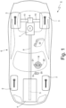
Figure 1 is a schematic and plan view of a rear-wheel drive vehicle provided with an automatic manual transmission that is controlled according to the control method of the present invention; -
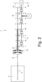
Figure 2 is a schematic view of the automatic manual transmission ofFigure 1 provided with a dual-clutch gearbox; -
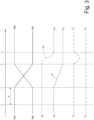
Figure 3 shows the time evolution during an upshift and conventional gear shift of the torques transmitted by the two clutches of the dual-clutch gearbox, the rotation speed of an engine drive shaft, the longitudinal acceleration of the vehicle, a torque objective of an internal combustion engine, and a torque objective of an electric machine; -
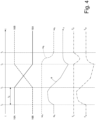
Figure 4 shows the time evolution during an upshift and innovative gear shift of the torques transmitted by the two clutches of the dual-clutch gearbox, the rotation speed of an engine drive shaft, the longitudinal acceleration of the vehicle, a torque objective of an internal combustion engine, and a torque objective of an electric machine; -
Figure 5 shows the time evolution during a downshift and conventional gear shift of the torques transmitted by the two clutches of the dual-clutch gearbox, the rotation speed of an engine drive shaft, the longitudinal acceleration of the vehicle, a torque objective of an internal combustion engine, and a torque objective of an electric machine; -
Figure 6 shows the time evolution during a downshift and innovative gear shift of the torques transmitted by the two clutches of the dual-clutch gearbox, the rotation speed of an engine drive shaft, the longitudinal acceleration of the vehicle, a torque objective of an internal combustion engine, and a torque objective of an electric machine; -
Figure 7 is a graph showing on an enlarged scale the time evolution of an additional torque profile ofFigure 4 ; and -
Figure 8 is a graph showing on an enlarged scale the time evolution of an additional torque profile ofFigure 6 . - In
Figure 1 , number 1 globally denotes a road vehicle (specifically a car) provided with twofront wheels 2 and tworear drive wheels 3. - The road vehicle 1 comprises an
internal combustion engine 4, which is arranged in the front, has adrive shaft 5 and produces a drive torque TE that is transmitted to therear drive wheels 3 via a manualautomatic transmission 6. Thetransmission 6 comprises a dual-clutch gearbox 7 arranged at the rear and atransmission shaft 8 connecting thedrive shaft 5 to an inlet of the gearbox 7. A self-locking differential 9, from which a pair ofaxle shafts 10 depart, each of which is integral to arear drive wheel 3, is connected in cascade to the gearbox 7. - In addition, the road vehicle 1 comprises at least one reversible electric machine 11 (i.e. one that can work either as an electric motor by absorbing electrical energy and generating a mechanical drive torque, or as an electric generator by absorbing mechanical energy and generating electrical energy). In the embodiment shown in the accompanying Figures, the shaft of the
electric machine 11 is connected to the gearbox 7, but alternatively the shaft of theelectric machine 11 could be connected to thedrive shaft 5 of theinternal combustion engine 4, to therear wheels 3 or to the front wheels 2 (which then become potentially drive wheels). - The
electric machine 11 is controlled by a corresponding AC/DC power electronic converter (i.e. an "inverter") that is connected to an electrical energy storage system provided with chemical batteries; i.e. the DC-AC power electronic converter is bidirectional and comprises a direct current side that is connected to the electrical energy storage system and a three-phase alternating side that is connected to theelectric machine 11. - As shown in
Figure 2 , the dual-clutch gearbox 7 comprises a pair ofprimary shafts 12 that are coaxial to each other, independent and inserted one inside the other. In addition, the dual-clutch gearbox 7 comprises twocoaxial clutches 13, each of which is adapted to connect a respectiveprimary shaft 12 to thedrive shaft 5 of theinternal combustion engine 4 through the interposition of thetransmission shaft 8. According to an alternative embodiment, eachclutch 13 is in an oil bath and is therefore commanded under pressure (i.e. the degree to which theclutch 13 opens/closes is determined by the pressure of the oil within the clutch 13); according to an alternative embodiment, eachclutch 13 is dry and is therefore commanded in position (i.e. the degree to which theclutch 13 opens/closes is determined by the position of a movable element of the clutch 13). - The dual-clutch gearbox 7 comprises a single
secondary shaft 14 connected to thedifferential 9 that transmits motion to therear drive wheels 3; according to an alternative and equivalent embodiment, the dual-clutch gearbox 7 comprises twosecondary shafts 14 both connected to thedifferential 9. In the embodiment shown in the enclosed figures, the shaft of theelectric machine 11 is connected to thesecondary shaft 14 of the gearbox 7. - As shown in
Figure 1 , the vehicle 1 comprises a cockpit, within which a driving position is formed with asteering wheel 18, anaccelerator pedal 19 and abrake pedal 20. The driver's place also comprises anupshift command 21 and adownshift command 22, which, as will be explained later, can be used by the driver to select a gear (generally in the case of performance driving on a circuit). Preferably, thecommands steering wheel 18 and are arranged behind the rim of thesteering wheel 18 to be activated without taking the hands off thesteering wheel 18. - The road vehicle 1 comprises a
control unit 23 that, among other things, oversees the operation of theinternal combustion engine 4, the dual-clutch gearbox 7, and theelectric machine 11. - In use, i.e. while the vehicle 1 is running, the
control unit 23 detects a position of theaccelerator pedal 19 and a position of thebrake pedal 20 to determine the driver's wishes about the gear modes. In addition, thecontrol unit 23 detects an actuation of theupshift command 21 and an actuation of thedownshift command 22 to determine the selected gear; that is, the selected gear is decided according to the actions on theupshift command 21 anddownshift command 22. - Furthermore, in use, the
control unit 23 determines a torque objective TE to be generated by theinternal combustion engine 4 and a torque objective TM to be generated by theelectric machine 11 depending on the position of the accelerator pedal 7 and depending on the selected gear; it is important to note that the torque objective TM can be positive (by operating theelectric machine 11 as an engine) or it can be negative (by operating theelectric machine 11 as a generator). In general, the torque objective TM is positive when the accelerator pedal 7 is at least partially pressed and is negative when the accelerator pedal 7 is released. - In other words, the
control unit 23 drives theinternal combustion engine 4 to pursue the torque objective TE and drives theelectric machine 11 to pursue the torque objective TM. - The modes of performing a gear shift from the current gear A to the following gear B when the driver acts on the
upshift command 21 ordownshift command 22 is described hereinafter. - In an initial situation (i.e. before the gear shift), a clutch 13A is closed to transmit motion to a primary shaft 12A, which in turn transmits motion to the
secondary shaft 14 via the current gear A that is engaged; a clutch 13B, on the other hand, is open and thus isolates a primary shaft 12B from thetransmission shaft 8. Before starting the upshift, the following gear B is engaged to connect through the gear B the primary shaft 12B to thesecondary shaft 14. When the driver sends the gear-shift command via thecommands drive shaft 5 of the internal combustion engine 4) and simultaneously closing the clutch 13B to connect the primary shaft 12B (thus the gear B) to the transmission shaft 8 (i.e. to thedrive shaft 5 of the internal combustion engine 4). -
Figure 3 shows the modes of an upshift and conventional gear shift, wherein at instant t0 the driver sends the gear-shift command (by acting on the upshift command 21). As soon as thecontrol unit 23 receives the gear-shift command from the driver (instant t0), thecontrol unit 23 immediately starts closing the clutch 13B associated with the following gear B; however, before the clutch 13B associated with the following gear B can start to transmit the torque to therear drive wheels 3 it is necessary to wait a certain filling time interval tR during which the filling of the oil inside the clutch 13B is completed. - From the instant t0 in which the
control unit 23 immediately starts to close the clutch 13B to the instant t1 in which, after the filling time tR has elapsed, the clutch 13B is filled with oil and is ready to start transmitting the torque, nothing happens to the dynamics of the road vehicle 1, i.e. all of the driving torque TE generated by theinternal combustion engine 4 is transmitted entirely by the clutch 13A as it was before the start of the gear shift. At instant t1 the opening of the clutch 13A is commanded; it is important to note that the opening of the clutch 13A associated with the current gear A occurs without any delay, as the clutch 13A is already full of oil under pressure and only has to be emptied of some of the oil at this step. - Between instants t1 and t2 the torque transfer between the two
clutches 13 takes place, i.e. the torque transmitted by the clutch 13A progressively falls and at the same time the torque transmitted by the clutch 13B progressively rises, resulting in a crossover between the twoclutches 13. Preferably (but not compulsorily), the clutch 13A is opened at the same time as the clutch 13B is fully closed so that a symmetrical crossover is obtained, which allows the overall torque transmitted to the rear drive wheels 3 (and thus the torque generated by the internal combustion engine 4) to remain constant. At instant t2, the clutch 13A is fully open (thus no longer transmitting the torque) while the clutch 13B is fully closed (thus transmitting all the drive torque) . - The longitudinal acceleration α of the vehicle 1 is in first approximation constant and equal to the value αA immediately before the gear shift, it decreases progressively towards the value αB during the gear shift, and is in first approximation constant and equal to the value αB immediately after the gear shift. The decrease in the longitudinal acceleration α of the vehicle 1 during the gear shift is due to the fact that the drive torque TE generated by the
internal combustion engine 4, which remains essentially constant, is transmitted with a progressively decreasing gear ratio (gear A is shorter than gear B) and thus a progressively decreasing drive torque is applied to therear drive wheels 3. - The rotation speed ωE of the
drive shaft 5 of theinternal combustion engine 4 is equal to the rotation speed ωA imposed by the gear ratio of the current gear A before the gear shift, it decreases progressively towards the rotation speed ωB imposed by the gear ratio of the following gear B during the gear shift, and is equal to the rotation speed ωB after the gear shift. As shown inFigure 3 , up to the instant t2 wherein the clutch 13A is fully open the rotation speed ωE of thedrive shaft 5 is kept constant and equal to the rotation speed ωA, and then is only decreased after the clutch 13A is fully open; this mode of controlling the rotation speed ωE of thedrive shaft 5 is intended to prevent the clutch 13A from becoming braking, i.e. generating a braking torque at therear drive wheels 3. - In order to decrease the rotation speed ωE of the
shaft 5 of theinternal combustion engine 4 after the complete opening of the clutch 13A, the control unit of theinternal combustion engine 4, upon indication of thecontrol unit 23, temporarily decreases the drive torque TE generated by theinternal combustion engine 4 while keeping the torque transmitted by the clutch 13B constant; as a result, a difference is created between the drive torque TE generated by theinternal combustion engine 4 and the torque transmitted by the clutch 13B (which is higher than the drive torque TE generated by the internal combustion engine 4), and this difference has the effect of decreasing the rotation speed ωE of theengine shaft 5 which passes from the initial value ωA imposed by the gear ratio of the current gear A to the final value ωB imposed by the gear ratio of the following gear B. In other words, for a short time therear drive wheels 3 receive both the mechanical energy generated by theinternal combustion engine 4 and part of the kinetic energy possessed by thedrive shaft 5 which slows down as a result. It is important to note that the temporary decrease in the drive torque TE generated by theinternal combustion engine 4 has no effect on the longitudinal acceleration α of the vehicle 1, as the torque transmitted by the clutch 13B to therear drive wheels 3 remains constant. - Throughout the gear shift, the
electric machine 11 always delivers the same torque, which therefore always remains constant (either a positive value, a null value or a negative value). In other words, theelectric machine 11 does not participate in any way in the operations that are carried out for gear shifting and therefore does not change its behaviour in any way during gear shifting. -
Figure 4 shows the modes of an upshift and innovative gear shift, wherein at instant t0 the driver sends the gear-shift command (by acting on the upshift command 21). - The upshift and innovative gear shift shown in
Figure 4 is, in terms of controlling the position of the clutches 13A and 13B and the control of the internal combustion engine 4 (i.e. the generation of the drive torque TE), entirely similarly to the upshift and conventional gear shift shown inFigure 3 and described above. On the other hand, during the upshift and innovative gear shift shown inFigure 4 , theelectric machine 11 is controlled differently and becomes an important player in the gear shift. During gear shifting, thecontrol unit 23 adds an additional torque profile Tadd (shown inFigure 7 ) to the torque objective TM of theelectric machine 11 which is impulsive and temporary and temporarily changes the development of the torque objective TM. In other words, when at instant t0 the driver selects a higher gear (as shown inFigure 4 ), thecontrol unit 23 adds the additional torque profile Tadd to the torque objective TM, which temporarily modifies the torque objective TM; in other words, throughout the duration of the additional torque profile Tadd (which starts at instant t0 and ends at instant t3), the torque objective TM is modified to become a modified torque objective TM. -
Figure 5 shows the modes of a downshift and conventional gear shift, wherein at instant t0 the driver sends the gear-shift command (acting on the downshift command 22); the downshift and conventional gear shift shown inFigure 5 is entirely similar to the upshift and conventional gear shift shown inFigure 3 and described above, with the difference that the longitudinal deceleration α of the vehicle 1 (i.e. the longitudinal acceleration α of the vehicle 1 having a negative value) progressively rises (in absolute value) from a lower initial value αA (in absolute value) towards a higher final value αB (in absolute value) . The increase (in absolute value) in the longitudinal deceleration α of the vehicle 1 during the gear shift is due to the fact that the braking torque TE (i.e. the engine brake which results in a negative drive torque TE) due to theinternal combustion engine 4 remaining essentially constant is transmitted with a progressively increasing gear ratio (gear A is longer than gear B) and thus a progressively increasing braking torque (in absolute value) is applied to therear drive wheels 3. - The rotation speed ωE of the
drive shaft 5 of theinternal combustion engine 4 is equal to the rotation speed ωA imposed by the gear ratio of the current gear A before the gear shift, it rises progressively towards the rotation speed ωB imposed by the gear ratio of the following gear B during the gear shift, and is equal to the rotation speed ωB after the gear shift. As shown inFigure 5 , up to the instant t2 when the clutch 13A is fully open, the rotation speed ωE of thedrive shaft 5 is kept constant and equal to the rotation speed ωA and then is only increased after the clutch 13A is fully open. - Throughout the gear shift, the
electric machine 11 always delivers the same torque, which therefore always remains constant (either a positive value, a null value or a negative value). In other words, theelectric machine 11 does not participate in any way in the operations that are carried out for gear shifting and therefore does not change its behaviour in any way during gear shifting. -
Figure 6 shows the modes of a downshift and innovative gear shift, wherein at instant t0 the driver sends the gear-shift command (by acting on the downshift command 22). - The downshift and innovative gear shift shown in
Figure 6 is, in terms of controlling the position of the clutches 13A and 13B and the control of the internal combustion engine 4 (i.e. the generation of drive torque TE), entirely similar to the downshift and conventional gear shift shown inFigure 5 and described above. On the other hand, during the downshift and innovative gear shift shown inFigure 6 , theelectric machine 11 is controlled differently and becomes an important player in the gear shift. During gear shifting, thecontrol unit 23 adds an additional torque profile Tadd (shown inFigure 8 ) to the torque objective TM of theelectric machine 11 which is impulsive and temporary and temporarily changes the development of the torque objective TM. In other words, when at instant t0 the driver selects a lower gear (as shown inFigure 6 ), thecontrol unit 23 adds the additional torque profile Tadd to the torque objective TM, which temporarily modifies the torque objective TM; in other words, throughout the duration of the additional torque profile Tadd (starting at instant t1 and ending at instant t3), the torque objective TM is modified to become a modified torque objective TM. - Summarising the above, in use, the
control unit 23 adds, at each variation in the selected gear, an additional torque profile Tadd (shown inFigures 7 and8 ) to the torque objective TM of theelectric machine 11, which is impulsive and temporary and temporarily modifies the development of the torque objective. - In other words, as shown in
Figures 7 and8 , when at instant t0, the driver selects a higher gear (as shown inFigures 4 and7 ) or a lower gear (as shown inFigures 6 and8 ), thecontrol unit 23 adds the additional torque profile Tadd to the torque objective TM of theelectric machine 11 which temporarily modifies the torque objective TM; i.e. throughout the duration of the additional torque profile Tadd (starting at instant t0 and ending at instant t3), the torque objective TM is modified to become a modified torque objective TM. - As best shown in
Figures 7 and8 , the additional torque profile Tadd comprises a start segment W having a first sign and an end segment X that immediately follows the start segment W and has a second sign opposite to the first sign; i.e., the additional torque profile Tadd involves alternating a torque increase/decrease with a subsequent torque decrease/increase. - Preferably, each segment W or X entails a torque increase, in absolute value, from zero to a maximum value TaddMAX or Taddmin and a following torque decrease from the maximum value TaddMAX or Taddmin to zero.
- Preferably, each segment W or X comprises at least one linear variation over time and at least one exponential variation over time.
- According to what shown in
Figure 7 , if the gear shift is up, the start segment W entails an always positive torque and the end segment X entails an always negative torque. In particular, the start segment W entails an exponential torque increase from zero (at instant t0) to a maximum positive value TaddMAX immediately followed by a linear decrease in torque from the maximum positive value TaddMAX to zero (at instant t4); on the other hand, the end segment X provides a linear torque decrease from zero (at instant t4) to a minimum negative value Taddmin immediately followed by an exponential increase from the minimum negative value Taddmin to zero (at instant t3). - According to the preferred (but non-binding) embodiment shown in
Figure 7 , the linear torque decrease from zero (at instant t4) to the minimum negative value Taddmin entails a higher initial slope followed by a lower final slope; i.e. the decrease is always linear but with a differentiated decrease speed (slope, first derivative in time): initially faster and subsequently slower. - According to what shown in
Figure 8 , if the gear shift is down, the start segment W entails an always negative torque and the end segment X entails an always positive torque. In particular, the start segment W entails an exponential torque decrease from zero (at instant t0) to a negative minimum value Taddmin immediately followed by a linear torque increase from the negative minimum value Taddmin to zero (at instant t4); on the other hand, the end segment X entails a toque increase from zero (at instant t4) to a positive maximum value TaddMAX value immediately followed by an exponential decrease from the positive maximum value TaddMAX to zero (at instant t3). - According to the preferred (but not binding) embodiment shown in
Figure 8 , the linear torque increase from zero (at instant t4) to the maximum positive value TaddMAX entails a linear increase immediately followed by an exponential increase. - According to a possible embodiment, the maximum value TaddMAX and the minimum value Taddmin are constant in absolute value. According to a different embodiment, the maximum value TaddMAX and the minimum value Taddmin are, in absolute value, variable, e.g. as a function of the absolute value of the drive torque objective TM; i.e., the maximum value TaddMAX and the minimum value Taddmin are in absolute value parametrised to the absolute value of the drive torque objective TM.
- According to a possible embodiment and as shown in
Figure 7 , in the case of upshifting, the maximum value TaddMAX is, in absolute value, greater than the minimum value Taddmin. - According to a possible embodiment and as shown in
Figure 8 , in the case of downshifting, the maximum value TaddMAX is, in absolute value, smaller than the minimum value Taddmin. - According to a possible embodiment and as shown in
Figures 4 and6 , the additional torque profile Tadd starts at instant t0 and ends at instant t3. - According to a possible embodiment and as shown in
Figures 4 and6 , an absolute maximum (corresponding to the maximum value TaddMAX) of the additional torque profile Tadd during the start segment W is reached between instant t0 and instant t1 (i.e. after instant t0 and before instant t1). - According to a possible embodiment and as shown in
Figures 4 and6 , 17 an absolute maximum (corresponding to the minimum value Taddmin) of the additional torque profile Tadd during the end segment X is reached at instant t2 (i.e. exactly coinciding with instant t2). - According to a possible embodiment and as shown in
Figures 4 and6 , the start segment W ends, and then the end segment X starts between instant t1 and instant t2 (i.e. after instant t1 and before instant t2). In the preferred embodiment shown in the appended Figures, the automaticmanual transmission 6 comprises a dual-clutch gearbox 7; according to a different embodiment not shown, the automaticmanual transmission 6 comprises a single-clutch gearbox 7. In any case, in order to change the drive gear from a current gear A to a subsequent gear B, at least one clutch 13 must be opened and closed, and during the gear shift, an additional torque profile Tadd is added to the torque objective TM of theelectric machine 11 which is impulsive and temporary and temporarily modifies the development of the torque objective TM. - The embodiments described herein can be combined with each other without departing from the scope of protection of the present invention.
- The control method described above has many advantages.
- First and foremost, the control method described above increases the driving pleasure, by virtue of the fact that the jerk given by the gear shift typical of a conventional car provided with an internal combustion engine and a single-clutch gearbox is obtained. In other words, the control method described above makes it possible to simulate the sporting effect of accelerometric variations typical of a single-clutch gearbox in a very realistic and engaging manner; furthermore, the control method described above makes it possible to create innovative accelerometric variations that cannot be physically achieved by a clutch gearbox, providing the driver with new and potentially very rewarding driving sensations.
- In other words, if during an up/down gear shift one only feels a more or less progressive decrease/increase in the longitudinal acceleration/deceleration of the vehicle 1 the sensation transmitted to the driver is flat and little involving as it is associated with modest performance (as it reminds of the sensations transmitted by an automatic transmission which is considered, rightly or wrongly, as extremely little sporty and performing); on the other hand, by creating, thanks to the addition of the additional torque profile Tadd to the torque objective TM generated by the
electric machine 11, an impulsive and clearly perceptible variation in the drive torque applied to the drive wheels when gearshifting, it is possible to transmit very pleasant and involving sensations to the driver. - Finally, the control method described above is simple and cost-effective to implement, as it does not require the addition of any physical components and can be completely software-implemented by exploiting the architectures already existing on board road vehicles 1. It is important to note that the method described above does not consume either a high computing capacity or a large amount of memory, and therefore its implementation is possible in a known control unit with no need for upgrades or enhancements.
-
- 1
- road vehicle
- 2
- front wheels
- 3
- rear wheels
- 4
- internal combustion engine
- 5
- drive shaft
- 6
- transmission
- 7
- gearbox
- 8
- transmission shaft
- 9
- differential
- 10
- axle shafts
- 11
- electric machine
- 12
- primary shafts
- 13
- clutches
- 14
- secondary shaft
- 15
- primary gearwheel
- 16
- secondary gearwheel
- 17
- synchronisers
- 18
- steering wheel
- 19
- accelerator pedal
- 20
- brake pedal
- 21
- upshift command
- 22
- downshift command
- 23
- control unit
- ωe
- rotation speed
- ωA
- rotation speed
- ωB
- rotation speed
- A
- previous gear
- B
- following gear
- tR
- filling time
- t0
- instant
- t1
- instant
- t2
- instant
- t3
- instant
- t4
- instant
- TE
- torque
- TM
- torque
- Tadd
- additional torque profile
- TaddMAX
- maximum value
- Taddmin
- minimum value
- W
- start segment
- X
- end segment
Claims (17)
- A control method to carry out a gear shift in a transmission (6) provided with a dual-clutch gearbox (7) and in a road vehicle (1) comprising an internal combustion engine (4) and at least one reversible electric machine (11); the dual-clutch gearbox (7) has two primary shafts (12), at least one secondary shaft (14) connected to drive wheels (3), and two clutches (13), each of which is interposed between a drive shaft (5) of the engine (4) and a corresponding primary shaft (12); the control method comprises the steps of:receiving a gear-shift command from a current gear (A) to a following gear (B);opening a first clutch (13A) associated with the current gear (A) and simultaneously closing a second clutch (13B) associated with the following gear (B);controlling, only and exclusively during the gear shift, the electric machine (11) to generate an additional torque profile (Tadd) which is impulsive and comprises a start segment (W) having a first sign and an end segment(X), which immediately follows the start segment (W) and has a second sign, which is contrary to the first sign;the control method is characterised in that if the gear shift is up the start segment (W) entails for an always positive torque and the final segment (X) entails an always negative torque, and if the gear shift is down the start segment (W) entails an always negative torque and the end segment (X) entails an always positive torque.
- The control method according to claim 1, wherein each segment (W, X) entails a torque increase, in absolute value, from zero to a maximum value (TaddMAX, Taddmin) and a following torque decrease from the maximum value (TaddMAX, Taddmin) to zero.
- The control method according to claim 1 or 2, wherein each segment (W, X) comprises at least one linear variation over time and at least one exponential variation over time.
- The control method according to claim 1, 2 or 3, wherein if the gear shift is up:the start segment (W) entails an exponential torque increase from zero to a maximum positive value (TaddMAX) immediately followed by a linear torque decrease from the maximum positive value (TaddMAX) to zero; andthe end segment (X) entails a linear torque decrease from zero to a minimum negative value (Taddmin) immediately followed by an exponential increase from the minimum negative value (Taddmin) to zero.
- The control method according to claim 4, wherein the linear torque decreases from zero to the minimum negative value (Taddmin) entails a greater start slope followed by a smaller end slope.
- The control method according to claim 4 or 5, wherein the maximum value (TaddMAX) is, in absolute value, greater than the minimum value (Taddmin).
- The control method according to one of claims 1 to 6, wherein if the gear shift is down:the start segment (W) entails an exponential torque decrease from zero to a minimum negative value (Taddmin) immediately followed by a linear torque increase from the minimum negative value (Taddmin) to zero; andthe end segment (X) entails a torque increase from zero to a maximum positive value (TaddMAX) immediately followed by an exponential decrease from the maximum positive value (TaddMAX) to zero.
- The control method according to claim 7, wherein the linear torque increase from zero to the maximum positive value (TaddMAX) entails a linear increase immediately followed by an exponential increase.
- The control method according to claim 7 or 8, wherein the maximum value (TaddMAX) is, in absolute value, smaller than the minimum value (Taddmin).
- The control method according to any one of the claims from 1 to 9, wherein the torque objective (TM) is positive, when an accelerator pedal (7) is at least partially pressed, and is negative, when the accelerator pedal (7) is released.
- The control method according to any one of the claims from 1 to 10 and comprising the steps of:opening the first clutch (13A) associated with the current gear (A) and closing the second clutch (13B) associated with the following gear (B) in a same first instant (t1); andcompleting the opening of the first clutch (13A) associated with the current gear (A) and completing the closing of the second clutch (13B) associated with the following gear (B) in a same second instant (t2) following the first instant (t1).
- The control method according to claim 11 and comprising the steps of:generating a gear-shift command at a third instant (t0) prior to the first instant (t1); andstarting the additional torque profile (Tadd) at the third instant (t0).
- The control method according to claim 12, wherein a maximum, in absolute value, of the additional torque profile (Tadd) during the start segment (W) is reached between the third instant (t0) and the first instant (t1).
- The control method according to claim 11, 12 or 13 and comprising the steps of:keeping the rotation speed (ωE) of the drive shaft (5) constant and equal to a start value (ωA) set by the gear ratio of the current gear (A) until the second instant (T2), wherein the opening of the first clutch (13A) is completed;varying progressively after the second instant (t2) the rotation speed (ωE) of the engine shaft (5) from the initial value (ωA) imposed by the gear ratio of the current gear (A) to a final value (ωB) imposed by the gear ratio of the following gear (B) until a fourth instant (t3) following the second instant (t2) at which the synchronisation of the speed (ωE) of rotation of the engine shaft (5) is completed; andterminating the additional torque profile (Tadd) at the fourth instant (t3).
- The control method according to any one of the claims 11 to 14, wherein the start segment (W) ends, and then the end segment (X) starts between the first instant (t1) and the second instant (t2).
- The control method according to any one of the claims from 11 to 15, wherein a maximum, in absolute value, of the additional torque profile (Tadd) during the end segment (X) is reached at the second instant (t2).
- The control method according to any one of the claims from 1 to 16 and comprising the steps of:determining a torque objective (TM) to be generated by the electric machine (11) irrespective of the gear shift;controlling the electric machine (11) so as to pursue the torque objective (TM); andadding, only and exclusively during the gear shift, to the torque objective (TM), the additional torque profile (Tadd), which is impulsive and temporarily changes the development of the torque objective (TM).
Applications Claiming Priority (1)
| Application Number | Priority Date | Filing Date | Title |
|---|---|---|---|
| IT102023000018561A IT202300018561A1 (en) | 2023-09-11 | 2023-09-11 | CONTROL METHOD FOR PERFORMING A GEAR CHANGE IN A TRANSMISSION EQUIPPED WITH A FRICTION GEAR CHANGE |
Publications (2)
| Publication Number | Publication Date |
|---|---|
| EP4521003A1 true EP4521003A1 (en) | 2025-03-12 |
| EP4521003B1 EP4521003B1 (en) | 2026-04-01 |
Family
ID=88690129
Family Applications (1)
| Application Number | Title | Priority Date | Filing Date |
|---|---|---|---|
| EP24199160.3A Active EP4521003B1 (en) | 2023-09-11 | 2024-09-09 | Control method for carrying out a gear shift in a transmission provided with a dual clutch gearbox |
Country Status (3)
| Country | Link |
|---|---|
| US (1) | US12320421B2 (en) |
| EP (1) | EP4521003B1 (en) |
| IT (1) | IT202300018561A1 (en) |
Families Citing this family (1)
| Publication number | Priority date | Publication date | Assignee | Title |
|---|---|---|---|---|
| IT202300018561A1 (en) | 2023-09-11 | 2025-03-11 | Ferrari Spa | CONTROL METHOD FOR PERFORMING A GEAR CHANGE IN A TRANSMISSION EQUIPPED WITH A FRICTION GEAR CHANGE |
Citations (5)
| Publication number | Priority date | Publication date | Assignee | Title |
|---|---|---|---|---|
| DE10308690A1 (en) | 2002-03-07 | 2003-10-30 | Luk Lamellen & Kupplungsbau | Gear changing strategy for automobile dual-clutch gearbox has input shaft of inactive parallel drive train increased during gear pre-selection |
| US20050164829A1 (en) * | 2004-01-27 | 2005-07-28 | Luk Lamellen Und Kupplungsbau Beteiligungs Kg | Method for upshifting of a parallel shaft gear |
| US20180112770A1 (en) * | 2015-05-04 | 2018-04-26 | Volvo Truck Corporation | Method for disengaging an inactive gear of a dual clutch transmission and a corresponding transmission |
| JP2021079877A (en) | 2019-11-21 | 2021-05-27 | アイシン・エィ・ダブリュ株式会社 | Drive device for vehicle |
| IT202300018561A1 (en) | 2023-09-11 | 2025-03-11 | Ferrari Spa | CONTROL METHOD FOR PERFORMING A GEAR CHANGE IN A TRANSMISSION EQUIPPED WITH A FRICTION GEAR CHANGE |
Family Cites Families (8)
| Publication number | Priority date | Publication date | Assignee | Title |
|---|---|---|---|---|
| JP2002526326A (en) * | 1998-10-02 | 2002-08-20 | ルーク ラメレン ウント クツプルングスバウ ベタイリグングス コマンディートゲゼルシャフト | Transmission having at least two shafts and an electric machine or automatic disc clutch |
| US6832978B2 (en) * | 2003-02-21 | 2004-12-21 | Borgwarner, Inc. | Method of controlling a dual clutch transmission |
| EP1507103B1 (en) * | 2003-08-14 | 2006-04-05 | Getrag Ford Transmissions GmbH | Method for shifting dual clutches |
| DE102010008754B4 (en) * | 2010-02-15 | 2025-02-06 | Dr. Ing. H.C. F. Porsche Aktiengesellschaft | drive system, in particular for a motor vehicle |
| US9365204B2 (en) * | 2013-12-12 | 2016-06-14 | GM Global Technology Operations LLC | Method and apparatus for torque arbitration and shaping in a multi-mode powertrain system |
| KR101558688B1 (en) * | 2013-12-13 | 2015-10-07 | 현대자동차주식회사 | Transmission for vehicle |
| US10967848B2 (en) * | 2016-10-31 | 2021-04-06 | Ford Global Technologies, Llc | Methods and systems for operating a driveline of a hybrid vehicle powertrain |
| KR102574116B1 (en) * | 2018-11-09 | 2023-09-05 | 현대자동차주식회사 | Vehicle and method for controlling the vehicle |
-
2023
- 2023-09-11 IT IT102023000018561A patent/IT202300018561A1/en unknown
-
2024
- 2024-09-09 US US18/828,218 patent/US12320421B2/en active Active
- 2024-09-09 EP EP24199160.3A patent/EP4521003B1/en active Active
Patent Citations (5)
| Publication number | Priority date | Publication date | Assignee | Title |
|---|---|---|---|---|
| DE10308690A1 (en) | 2002-03-07 | 2003-10-30 | Luk Lamellen & Kupplungsbau | Gear changing strategy for automobile dual-clutch gearbox has input shaft of inactive parallel drive train increased during gear pre-selection |
| US20050164829A1 (en) * | 2004-01-27 | 2005-07-28 | Luk Lamellen Und Kupplungsbau Beteiligungs Kg | Method for upshifting of a parallel shaft gear |
| US20180112770A1 (en) * | 2015-05-04 | 2018-04-26 | Volvo Truck Corporation | Method for disengaging an inactive gear of a dual clutch transmission and a corresponding transmission |
| JP2021079877A (en) | 2019-11-21 | 2021-05-27 | アイシン・エィ・ダブリュ株式会社 | Drive device for vehicle |
| IT202300018561A1 (en) | 2023-09-11 | 2025-03-11 | Ferrari Spa | CONTROL METHOD FOR PERFORMING A GEAR CHANGE IN A TRANSMISSION EQUIPPED WITH A FRICTION GEAR CHANGE |
Also Published As
| Publication number | Publication date |
|---|---|
| IT202300018561A1 (en) | 2025-03-11 |
| EP4521003B1 (en) | 2026-04-01 |
| US20250084922A1 (en) | 2025-03-13 |
| US12320421B2 (en) | 2025-06-03 |
Similar Documents
| Publication | Publication Date | Title |
|---|---|---|
| US7094176B2 (en) | Method for carrying out gear shifting in a twin-clutch gearbox | |
| JP3415123B2 (en) | Apparatus and method for active transmission synchronization and shifting | |
| US20130035817A1 (en) | Land vehicle driven by an electric or hydraulic motor | |
| WO2020025860A1 (en) | A control arrangement of an electric car | |
| ITUB20153377A1 (en) | CONTROL METHOD FOR THE EXECUTION OF A GEAR CHANGE IN A TRANSMISSION PROVIDED WITH A DOUBLE CLUTCH CHANGE | |
| CN100532890C (en) | Transmission control device and automobile transmission device | |
| EP4521003B1 (en) | Control method for carrying out a gear shift in a transmission provided with a dual clutch gearbox | |
| JP4887058B2 (en) | Control apparatus and control method for automobile | |
| KR20060041679A (en) | Method and apparatus for shift stage switching control in a parallel transmission of a vehicle | |
| EP2947355B1 (en) | Starting clutch control device for automatic transmission | |
| KR20250094865A (en) | Torque control system and method for drive system of electric vehicle | |
| US12606031B2 (en) | Method to control an electric road vehicle | |
| JP2013022999A (en) | Power transmission control device for vehicle | |
| CN116890657A (en) | Control method for an electric road vehicle driven by a driver and related road vehicles | |
| CN100487273C (en) | Automobile controller, automobile control method and automatic transmission | |
| EP1205685B1 (en) | Automatic transmission for vehicles | |
| CN112572446B (en) | Method of controlling a shift to a lower gear with the accelerator pedal released | |
| JP7572821B2 (en) | Method for controlling the execution of a shift to a lower gear while the accelerator pedal is released in a drivetrain having a dual clutch servo-assisted transmission - Patent 7336963 | |
| CN112572447B (en) | Method of controlling the shift to a higher gear with the accelerator pedal released | |
| JP7536578B2 (en) | Method for automatically controlling a drivetrain having a servo-assisted transmission - Patents.com | |
| JP7750075B2 (en) | Automatic transmission control device | |
| EP4520578A1 (en) | Control method for an electric road vehicle and related road vehicle | |
| ITUB20153395A1 (en) | CONTROL METHOD FOR THE EXECUTION OF A GEAR CHANGE IN A TRANSMISSION PROVIDED WITH A DOUBLE CLUTCH CHANGE | |
| EP4416025A1 (en) | Down-shift acceleration overshoot compensation in automotive electronic longitudinal dynamics control of autonomous motor vehicles | |
| JP2006226206A (en) | Control device and control method for automatic transmission |
Legal Events
| Date | Code | Title | Description |
|---|---|---|---|
| PUAI | Public reference made under article 153(3) epc to a published international application that has entered the european phase |
Free format text: ORIGINAL CODE: 0009012 |
|
| STAA | Information on the status of an ep patent application or granted ep patent |
Free format text: STATUS: THE APPLICATION HAS BEEN PUBLISHED |
|
| AK | Designated contracting states |
Kind code of ref document: A1 Designated state(s): AL AT BE BG CH CY CZ DE DK EE ES FI FR GB GR HR HU IE IS IT LI LT LU LV MC ME MK MT NL NO PL PT RO RS SE SI SK SM TR |
|
| STAA | Information on the status of an ep patent application or granted ep patent |
Free format text: STATUS: REQUEST FOR EXAMINATION WAS MADE |
|
| 17P | Request for examination filed |
Effective date: 20250708 |
|
| GRAP | Despatch of communication of intention to grant a patent |
Free format text: ORIGINAL CODE: EPIDOSNIGR1 |
|
| STAA | Information on the status of an ep patent application or granted ep patent |
Free format text: STATUS: GRANT OF PATENT IS INTENDED |
|
| RIC1 | Information provided on ipc code assigned before grant |
Ipc: F16H 61/688 20060101AFI20251007BHEP Ipc: B60W 30/19 20120101ALI20251007BHEP Ipc: B60W 10/06 20060101ALI20251007BHEP Ipc: B60W 10/08 20060101ALI20251007BHEP Ipc: B60W 10/113 20120101ALI20251007BHEP |
|
| INTG | Intention to grant announced |
Effective date: 20251031 |
|
| GRAS | Grant fee paid |
Free format text: ORIGINAL CODE: EPIDOSNIGR3 |
|
| GRAA | (expected) grant |
Free format text: ORIGINAL CODE: 0009210 |
|
| STAA | Information on the status of an ep patent application or granted ep patent |
Free format text: STATUS: THE PATENT HAS BEEN GRANTED |
|
| AK | Designated contracting states |
Kind code of ref document: B1 Designated state(s): AL AT BE BG CH CY CZ DE DK EE ES FI FR GB GR HR HU IE IS IT LI LT LU LV MC ME MK MT NL NO PL PT RO RS SE SI SK SM TR |
|
| REG | Reference to a national code |
Ref country code: CH Ref legal event code: F10 Free format text: ST27 STATUS EVENT CODE: U-0-0-F10-F00 (AS PROVIDED BY THE NATIONAL OFFICE) Effective date: 20260401 Ref country code: GB Ref legal event code: FG4D |
|
| REG | Reference to a national code |
Ref country code: DE Ref legal event code: R096 Ref document number: 602024003613 Country of ref document: DE |
|
| REG | Reference to a national code |
Ref country code: IE Ref legal event code: FG4D |