EP4520994A1 - Brake dust filter system - Google Patents
Brake dust filter system Download PDFInfo
- Publication number
- EP4520994A1 EP4520994A1 EP23195574.1A EP23195574A EP4520994A1 EP 4520994 A1 EP4520994 A1 EP 4520994A1 EP 23195574 A EP23195574 A EP 23195574A EP 4520994 A1 EP4520994 A1 EP 4520994A1
- Authority
- EP
- European Patent Office
- Prior art keywords
- brake dust
- filter system
- dust filter
- particle
- airflow
- Prior art date
- Legal status (The legal status is an assumption and is not a legal conclusion. Google has not performed a legal analysis and makes no representation as to the accuracy of the status listed.)
- Granted
Links
Images



Classifications
-
- F—MECHANICAL ENGINEERING; LIGHTING; HEATING; WEAPONS; BLASTING
- F16—ENGINEERING ELEMENTS AND UNITS; GENERAL MEASURES FOR PRODUCING AND MAINTAINING EFFECTIVE FUNCTIONING OF MACHINES OR INSTALLATIONS; THERMAL INSULATION IN GENERAL
- F16D—COUPLINGS FOR TRANSMITTING ROTATION; CLUTCHES; BRAKES
- F16D65/00—Parts or details
- F16D65/0031—Devices for retaining friction material debris, e.g. dust collectors or filters
Definitions
- the present invention refers to a brake dust filter system for a vehicle, the brake dust filter system comprising:
- Brake dust filters are used to capture brake dust emerging from wheel brakes of vehicles. By capturing the brake dust, staining of components arranged adjacent to the wheel brake, such as rims, can be avoided. Furthermore, pollution of the environment by the brake dust can be reduced. Release of brake dust into the environment is increasingly seen as problematic, since brake dust contributes to the fine dust emission of the vehicle, which is considered harmful for living beings.
- US 9,726,241 B2 discloses a nonpolluting brake assembly comprising a rotor, a pad comprising friction material capable of releasing particles resulting from abrasion, an autonomous suction device for drawing off said particles which comprises an intake opening arranged in the immediate vicinity of the pad and the rotor, a collection chamber for collecting the particles, an impeller driven by the rotor by means of a roller pressing on the rotor, for drawing off the particles through the opening and propelling them into the collection chamber, such that the particles are trapped as close as possible to their emission.
- the collection chamber may comprise a filter of fibrous media.
- EP 2 585 730 B1 discloses a disc brake comprising a brake caliper, which overlaps a brake disc and in which are arranged brake pads provided with friction linings, each of which can be pressed with its friction lining on both sides against friction rings of the brake disc, the friction rings being covered outside the region of overlap of the friction linings by a housing, which is stationary with respect to the brake caliper and is connected to a suction device.
- the housing consists of two covering parts covering the respective friction ring in the manner of hoods, and a dust removal device is provided between the housing and the suction device.
- the dust removal device arranged between the suction device and the housing preferably consists of a coarse dust separator arranged first in the direction of the housing, through which the contaminated, extracted air is led to a fine dust filter, which is connected upstream of the suction device, preferably a suction fan, while a muffler is provided downstream of the suction fan, through which the purified air is led outside.
- a brake dust filter system for a vehicle is provided.
- the vehicle can be e.g. a road vehicle, a rail vehicle, or an airplane.
- the vehicle generally has wheels.
- the vehicle has at least one wheel brake assembly, typically one wheel brake assembly per wheel.
- the wheel brake assembly can comprise drum brakes as well as disc brakes.
- the brake dust filter system comprises at least one suction port configured to be positioned near a wheel brake assembly of the vehicle in an installed state of the brake dust filter system.
- the at least one suction port is arranged at a suction bracket at least partially engaging around a brake disk.
- the suction bracket can be part of a brake caliper or can be mounted to a brake caliper.
- the brake dust filter system further comprises a duct arrangement and an airflow generation device configured to generate an airflow from the at least one suction port through the duct arrangement towards the airflow generation device.
- the airflow generation device is configured to generate an airflow that allows sucking particles generated by the wheel brake assembly into the at least one suction port.
- the duct arrangement fluidically couples the at least one suction port and the airflow generation device.
- the airflow generation device which is connected to the at least one suction port, significantly reduces the amount of brake dust particles that may escape into the environment.
- the duct arrangement comprises at least one air duct (e.g. a pipe or a hose).
- the airflow generation device may be a suction pump.
- the airflow generation device may comprise an impeller.
- the brake dust filter system comprises a particle filter element fluidically coupled to the duct arrangement and arranged downstream of the at least one suction port.
- the filter element may comprise a filter medium body of pleated filter paper. Alternatively or additionally, the filter element may comprise a filter medium body of porous foam.
- the particle filter element is arranged such that the airflow passes through the particle filter element.
- the particle filter element is configured to retain at least a portion of particles contained in the airflow out of said the airflow.
- the airflow generation device may be arranged upstream of the particle filter element.
- the duct arrangement extends beyond the airflow generation device in flow direction.
- the airflow generation device is preferably arranged downstream of the particle filter element.
- the airflow generation device is exposed to few brake dust particles (preferably, only a negligible amount of brake dust particles passes the particle filter element). Consequently, wear and tear of the airflow generation device is reduced.
- the particle filter element may comprise a coarse filter medium body and a fine filter medium body arranged downstream of the coarse filter medium body. In this way, a particular high retention rate of even very small brake dust particles (e.g. having an equivalent diameter of less than 1 ⁇ m) can be obtained.
- the brake dust filter system comprises an inertial separator fluidically coupled to the duct arrangement and arranged upstream of the particle filter element and downstream of the at least one suction port.
- the inertial separator comprises:
- the inertial separator reduces the amount of larger brake dust particles (e.g. having an equivalent diameter of more than 1 ⁇ m, in particular more than 2.5 ⁇ m), which are led to the particle filter element. These larger particles would clog the particle filter element in relatively short time. Thus, by providing the inertial separator, service intervals can be prolonged, and maintenance cost can be reduced.
- larger brake dust particles e.g. having an equivalent diameter of more than 1 ⁇ m, in particular more than 2.5 ⁇ m
- the raw air inlet serves to connect the inertial separator to the at least one suction port.
- one air duct is arranged between each suction port and each raw air inlet. It is understood that multiple suction ports can be connected to one common raw air inlet using appropriate ducting.
- Particles separated from the airflow in the inertial separator are ejected through the at least one particle outlet. Thus, these particles do not accumulate inside the inertial separator and do not clog the inertial separator.
- the airflow purified from the larger particles is fed to the particle filter element through the at least one air outlet.
- one air duct to the particle filter element is provided for each air outlet of the inertial separator.
- Multiple air outlets at the inertial separator and air ducts to the particle filter element may increase the separation efficiency of the inertial separator and/or the particle filter element.
- the at least one particle outlet is connected to a particle collection chamber.
- Brake dust particles which have been separated from the airflow in the inertial separator, enter the particle collection chamber through the at least one particle outlet and they are retained inside the particle collection chamber.
- the particle collection chamber is arranged below the inertial separator. This simplifies guiding the particles into the particle collection chamber. The particles may just fall into the particle collection chamber due to gravitation.
- the particle collection chamber may have a volume of at least 0.3 I, preferably at least 0.4 I, particularly preferably at least 0.5 I.
- the particle collection chamber may have a volume of at most 1 I, preferably at most 0.75 I. These volumes have been found to allow for reasonable intervals, e.g. every 25.000 km for a road vehicle, between emptying the particle collection chamber, while keeping its dimensions limited. For railway application the chamber volume can be up to 3 L.
- the efficiency of the brake dust filter system can be increased.
- particle filter elements which are capable of retaining very fine particles, can be employed without and excessive clogging of the particle filter element and without the need for frequent replacement thereof.
- a vehicle comprising the brake dust filter system may have one such system per axis or one system for all of its wheels.
- a brake system comprising at least one wheel brake assembly and the brake dust filter system may have one such brake dust filter system for one wheel brake assembly, for two-wheel brake assemblies or for four-wheel brake assemblies.
- the inertial separator is received in a separator housing, and the separator housing comprises the raw air inlet and the at least one air outlet.
- the separator housing comprises the raw air inlet and the at least one air outlet.
- the raw air inlet and the at least one air outlet may be provided as ports, which are coupled to the duct arrangement.
- the separator housing comprises a detachable cover for the particle collection chamber. This facilitates emptying the particle collection chamber during routine maintenance.
- the cover is screwed to a housing body of the separator housing.
- the cover and the housing body may each comprise mating threads.
- the raw air inlet and the at least one air outlet are comprised at an upper side of the separator housing.
- This arrangement requires the airflow to change its direction inside the separator housing, which supports the separation efficiency of the inertial separator.
- the at least one air outlet being arranged above the inertial separator and the particle collection chamber being arranged below the inertial separator, the risk of particles, which have already been separated from the airflow, being sucked out of the particle collection chamber and fed to the particle filter element is significantly reduced.
- the particle filter element may be received in a filter housing, and the filter housing comprises at least one connection port coupled to the duct arrangement.
- the filter housing comprises at least one connection port coupled to the duct arrangement.
- multiple connection ports are provided at the filter housing. Multiple connection may contribute to establish a uniform flow pattern through the particle filter element. This allows better exploiting the entire particle accumulation capacity of the particle filter element.
- the airflow generation device may be attached to the filter housing. It is also conceivable, that the airflow generation device be received inside the filter housing, in particular downstream of the particle filter element.
- the inertial separator comprises at least one cyclone separator.
- Cyclone separators have been found to be efficient in separation of brake dust particles. Further, it was found that the separation efficiency of cyclone separators does not significantly decrease upon permanent exposure to brake dust.
- the cyclone separator may be an axial cyclone separator or a tangential cyclone separator. In an axial cyclone separator, the inflow of air is in axial direction of the cyclone. In a tangential cyclone separator, the inflow of air is in tangential direction of the cyclone.
- the raw air inlet is fluidically coupled to multiple cyclone separators through multiple flow windows, wherein the cyclone separators are arranged around the raw air inlet.
- the cyclone separators are arranged around the raw air inlet.
- one raw air inlet or the one raw air inlet is surrounded by multiple flow windows and by multiple cyclone separators.
- multiple cyclone separators and flow windows are provided for each raw air inlet.
- One or multiple flow windows may be provided per cyclone separator. This design provides for a particular high separation efficiency in the inertial separator.
- the inertial separator comprises a nozzle structure, which is fluidically coupled to the raw air inlet, and at least one baffle structure, which is arranged to be encountered by the (particle-laden) airflow after passing through the nozzle structure.
- the at least one baffle structure may be referred to as a structure deflector plate.
- the nozzle structure accelerates the particle-laden airflow passing through its nozzle holes.
- a diameter of nozzle holes of the nozzle structure is preferably at least 2 mm and/or at most 3 mm.
- a distance of the at least one baffle structure to the nozzle structure may be at least 1 mm and/or at most 3 mm, preferably 2 mm. It has been found that these dimensions allow for a high separation efficiency, which is maintained during continuous exposure of the inertial separator to brake dust.
- the at least one baffle structure may comprise spikes facing towards the nozzle structure.
- the spikes provide for an efficient deceleration of the brake dust particles, while allowing the air to travel along the spiked surface of the at least one baffle structure. This design further increases the separation efficiency of the inertial separator.
- the nozzle structure may comprise a center pipe with radially oriented nozzle holes, preferably wherein the center pipe has a polygonal, e.g. hexagonal, cross section.
- Compact outer dimensions of an inertial separator can be obtained with this design, while the inertial separator allows for high volume flow and high separation rates.
- the center pipe is generally closed at its axial end remote from the raw air inlet. Thus, the airflow is forced to pass through the nozzle holes.
- the at least one baffle structure may surround the center pipe, preferably wherein multiple baffle plates are arranged in a polygonal, e.g. hexagonal, shape.
- a basically square angle of incidence of the airflow passing through each of the nozzle holes on the associated baffle plate can be established with this design.
- Figure 1 shows a brake dust filter system 10 arranged at two-wheel brake assemblies 12, which are disk brakes in the depicted embodiment.
- the wheel brake assemblies 12 are part of a vehicle having wheels, such as a passenger car (not depicted).
- the wheel brake assemblies 12 each comprise a brake disk 14 and a caliper 16 engaging around the associated brake disk 14.
- a suction bracket 18 of the brake dust filter system 10 is attached to each of the brake calipers 16 and engages around the associated brake disk 14.
- Each suction bracket 18 provides two suction ports 20 arranged on either side of the brake disk 14.
- the suction brackets 18 with the suction ports 20 are arranged behind the brake calipers 16 with respect to a usual direction of rotation of the brake disk 14 (vehicle traveling forward).
- the brake dust filter system 10 further comprises an inertial separator 22, a particle filter element 24 and an airflow generation device 26.
- a duct arrangement 28 comprising several air ducts 30, 32, here flexible hoses, fluidically connects the suction brackets 18 to the inertial separator 22 and the inertial separator 22 to the partricle filter element 24.
- the filter housing 34 has two connection ports 36 which each receive one of the air ducts 32, which lead pre-cleaned air from the inertial separator 22 to the particle filter element 24.
- a raw air inlet 44 is provided at the center of an upper side 46 of a separator housing 48.
- the raw air inlet 44 comprises two inlet ports 50 each for connecting one of the air ducts 30 coming from the suction ports 20.
- the particle collection chamber 70 is formed in the separator housing 48 and is arranged below the cyclone separators 58.
- the separator housing 48 comprises a housing body 72 and a cover 74. Mating threads are provided on the housing body 72 and the cover 74. In the mounted state, the cover 74 closes the particle collection chamber 70 at the bottom. When the cover 74 is unscrewed from the housing body 72, the particle collection chamber 70 can be emptied.
- a baffle structure 86 surrounds the center pipe 76.
- the baffle structure 86 comprises six baffle plates 88.
- the baffle structure 86 is designed as a cricumferentially closed baffle pipe with polygonal cross section, which baffle pipe surronds the center pipe 76.
- the baffle plates 88 are mounted or formed inside the baffle pipe.
- Each baffle plate 88 has a multitude of spikes 90 facing towards the center pipe 76.
Landscapes
- Engineering & Computer Science (AREA)
- General Engineering & Computer Science (AREA)
- Mechanical Engineering (AREA)
- Separating Particles In Gases By Inertia (AREA)
Abstract
Description
- The present invention refers to a brake dust filter system for a vehicle, the brake dust filter system comprising:
- at least one suction port configured to be positioned near a wheel brake assembly of the vehicle in an installed state of the brake dust filter system;
- a duct arrangement;
- an airflow generation device configured to generate an airflow from the at least one suction port through the duct arrangement towards the airflow generation device; and
- a particle filter element fluidically coupled to the duct arrangement and arranged downstream of the at least one suction port.
- A brake dust filter system of this kind is known e.g. from
EP 2 585 730 B1 . - Brake dust filters are used to capture brake dust emerging from wheel brakes of vehicles. By capturing the brake dust, staining of components arranged adjacent to the wheel brake, such as rims, can be avoided. Furthermore, pollution of the environment by the brake dust can be reduced. Release of brake dust into the environment is increasingly seen as problematic, since brake dust contributes to the fine dust emission of the vehicle, which is considered harmful for living beings.
- Passive brake dust filters use the immanent airflow caused by the motion of the vehicle or the rotation of the brakes to direct brake dust laden air through a filter device. Active brake dust filter systems use additional devices, such as impellers, to force the brake dust particle laden airflow through a filter device.
-
US 9,726,241 B2 -
EP 2 084 423 B1 describes a filter arrangement for brake dust retention systems on braking devices for motor vehicle wheels, with a suction device on the respective braking device and with a filter element in the suction path for the air enriched with the brake dust. In order to achieve a simple and inexpensive solution also with regard to the maintenance of the filter arrangement, a filter element already present in the motor vehicle, namely an exhaust gas filter or a filter for the interior ventilation, is used as a filter element to form a common one-piece filter element. -
EP 2 585 730 B1 , already mentioned above, discloses a disc brake comprising a brake caliper, which overlaps a brake disc and in which are arranged brake pads provided with friction linings, each of which can be pressed with its friction lining on both sides against friction rings of the brake disc, the friction rings being covered outside the region of overlap of the friction linings by a housing, which is stationary with respect to the brake caliper and is connected to a suction device. The housing consists of two covering parts covering the respective friction ring in the manner of hoods, and a dust removal device is provided between the housing and the suction device. The dust removal device arranged between the suction device and the housing preferably consists of a coarse dust separator arranged first in the direction of the housing, through which the contaminated, extracted air is led to a fine dust filter, which is connected upstream of the suction device, preferably a suction fan, while a muffler is provided downstream of the suction fan, through which the purified air is led outside. - It is an object of the invention to provide a brake dust filter system with high dust retention efficiency, which requires little maintenance.
- This is achieved by a brake dust filter system according to claim 1. Advantageous embodiments are given in the subclaims and the description.
- In accordance with the invention, a brake dust filter system for a vehicle is provided. The vehicle can be e.g. a road vehicle, a rail vehicle, or an airplane. The vehicle generally has wheels. Generally, the vehicle has at least one wheel brake assembly, typically one wheel brake assembly per wheel. The wheel brake assembly can comprise drum brakes as well as disc brakes.
- The brake dust filter system comprises at least one suction port configured to be positioned near a wheel brake assembly of the vehicle in an installed state of the brake dust filter system. Preferably, the at least one suction port is arranged at a suction bracket at least partially engaging around a brake disk. In particular, the suction bracket can be part of a brake caliper or can be mounted to a brake caliper.
- The brake dust filter system further comprises a duct arrangement and an airflow generation device configured to generate an airflow from the at least one suction port through the duct arrangement towards the airflow generation device. In other words, the airflow generation device is configured to generate an airflow that allows sucking particles generated by the wheel brake assembly into the at least one suction port. The duct arrangement fluidically couples the at least one suction port and the airflow generation device. The airflow generation device, which is connected to the at least one suction port, significantly reduces the amount of brake dust particles that may escape into the environment. The duct arrangement comprises at least one air duct (e.g. a pipe or a hose). The airflow generation device may be a suction pump. The airflow generation device may comprise an impeller.
- The brake dust filter system comprises a particle filter element fluidically coupled to the duct arrangement and arranged downstream of the at least one suction port. The filter element may comprise a filter medium body of pleated filter paper. Alternatively or additionally, the filter element may comprise a filter medium body of porous foam. The particle filter element is arranged such that the airflow passes through the particle filter element. The particle filter element is configured to retain at least a portion of particles contained in the airflow out of said the airflow.
- The airflow generation device may be arranged upstream of the particle filter element. In this embodiment, the duct arrangement extends beyond the airflow generation device in flow direction.
- However, the airflow generation device is preferably arranged downstream of the particle filter element. In this embodiment, the airflow generation device is exposed to few brake dust particles (preferably, only a negligible amount of brake dust particles passes the particle filter element). Consequently, wear and tear of the airflow generation device is reduced.
- The particle filter element may comprise a coarse filter medium body and a fine filter medium body arranged downstream of the coarse filter medium body. In this way, a particular high retention rate of even very small brake dust particles (e.g. having an equivalent diameter of less than 1 µm) can be obtained.
- According to the invention, the brake dust filter system comprises an inertial separator fluidically coupled to the duct arrangement and arranged upstream of the particle filter element and downstream of the at least one suction port. The inertial separator comprises:
- a raw air inlet for the airflow from the at least one suction port;
- at least one particle outlet for particles that are separated from the airflow by the intertial separator; and
- at least one air outlet for the airflow towards the particle filter element.
- The inertial separator reduces the amount of larger brake dust particles (e.g. having an equivalent diameter of more than 1 µm, in particular more than 2.5 µm), which are led to the particle filter element. These larger particles would clog the particle filter element in relatively short time. Thus, by providing the inertial separator, service intervals can be prolonged, and maintenance cost can be reduced.
- The raw air inlet serves to connect the inertial separator to the at least one suction port. Preferably, one air duct is arranged between each suction port and each raw air inlet. It is understood that multiple suction ports can be connected to one common raw air inlet using appropriate ducting.
- Particles separated from the airflow in the inertial separator are ejected through the at least one particle outlet. Thus, these particles do not accumulate inside the inertial separator and do not clog the inertial separator.
- The airflow purified from the larger particles is fed to the particle filter element through the at least one air outlet. Preferably, one air duct to the particle filter element is provided for each air outlet of the inertial separator. Multiple air outlets at the inertial separator and air ducts to the particle filter element may increase the separation efficiency of the inertial separator and/or the particle filter element.
- The at least one particle outlet is connected to a particle collection chamber. Brake dust particles, which have been separated from the airflow in the inertial separator, enter the particle collection chamber through the at least one particle outlet and they are retained inside the particle collection chamber. Preferably, the particle collection chamber is arranged below the inertial separator. This simplifies guiding the particles into the particle collection chamber. The particles may just fall into the particle collection chamber due to gravitation.
- The particle collection chamber may have a volume of at least 0.3 I, preferably at least 0.4 I, particularly preferably at least 0.5 I. The particle collection chamber may have a volume of at most 1 I, preferably at most 0.75 I. These volumes have been found to allow for reasonable intervals, e.g. every 25.000 km for a road vehicle, between emptying the particle collection chamber, while keeping its dimensions limited. For railway application the chamber volume can be up to 3 L.
- In summary, by providing the inertial separator, which removes in particular larger particles form the airflow, the efficiency of the brake dust filter system can be increased. In particular, particle filter elements, which are capable of retaining very fine particles, can be employed without and excessive clogging of the particle filter element and without the need for frequent replacement thereof.
- A vehicle comprising the brake dust filter system may have one such system per axis or one system for all of its wheels. A brake system comprising at least one wheel brake assembly and the brake dust filter system may have one such brake dust filter system for one wheel brake assembly, for two-wheel brake assemblies or for four-wheel brake assemblies.
- Preferably, the inertial separator is received in a separator housing, and the separator housing comprises the raw air inlet and the at least one air outlet. This facilitates connecting the inertial separator to the at least one suction port, to the particle filter element and to the particle collection chamber. The raw air inlet and the at least one air outlet may be provided as ports, which are coupled to the duct arrangement.
- In a particularly preferred embodiment, the separator housing comprises a detachable cover for the particle collection chamber. This facilitates emptying the particle collection chamber during routine maintenance. Preferably, the cover is screwed to a housing body of the separator housing. The cover and the housing body may each comprise mating threads.
- Preferably, the raw air inlet and the at least one air outlet are comprised at an upper side of the separator housing. This arrangement requires the airflow to change its direction inside the separator housing, which supports the separation efficiency of the inertial separator. Further, with the at least one air outlet being arranged above the inertial separator and the particle collection chamber being arranged below the inertial separator, the risk of particles, which have already been separated from the airflow, being sucked out of the particle collection chamber and fed to the particle filter element is significantly reduced.
- The particle filter element may be received in a filter housing, and the filter housing comprises at least one connection port coupled to the duct arrangement. Preferably, multiple connection ports are provided at the filter housing. Multiple connection may contribute to establish a uniform flow pattern through the particle filter element. This allows better exploiting the entire particle accumulation capacity of the particle filter element.
- The airflow generation device may be attached to the filter housing. It is also conceivable, that the airflow generation device be received inside the filter housing, in particular downstream of the particle filter element.
- In a particularly preferred embodiment, the inertial separator comprises at least one cyclone separator. Cyclone separators have been found to be efficient in separation of brake dust particles. Further, it was found that the separation efficiency of cyclone separators does not significantly decrease upon permanent exposure to brake dust. The cyclone separator may be an axial cyclone separator or a tangential cyclone separator. In an axial cyclone separator, the inflow of air is in axial direction of the cyclone. In a tangential cyclone separator, the inflow of air is in tangential direction of the cyclone.
- Preferably, the raw air inlet is fluidically coupled to multiple cyclone separators through multiple flow windows, wherein the cyclone separators are arranged around the raw air inlet. In other words, one raw air inlet or the one raw air inlet is surrounded by multiple flow windows and by multiple cyclone separators. In particular, multiple cyclone separators and flow windows are provided for each raw air inlet. One or multiple flow windows may be provided per cyclone separator. This design provides for a particular high separation efficiency in the inertial separator.
- Another preferred embodiment provides that the inertial separator comprises a nozzle structure, which is fluidically coupled to the raw air inlet, and at least one baffle structure, which is arranged to be encountered by the (particle-laden) airflow after passing through the nozzle structure. The at least one baffle structure may be referred to as a structure deflector plate. The nozzle structure accelerates the particle-laden airflow passing through its nozzle holes. When the airflow with the particles encounters the at least one baffle structure, the (heavy) particles hit the so-called structure deflector plate, while the airflow (without heavy particles or at least with less particles) is directed to the at least one air outlet.
- A diameter of nozzle holes of the nozzle structure is preferably at least 2 mm and/or at most 3 mm. A distance of the at least one baffle structure to the nozzle structure (measured in flow direction of the airflow through the nozzle holes) may be at least 1 mm and/or at most 3 mm, preferably 2 mm. It has been found that these dimensions allow for a high separation efficiency, which is maintained during continuous exposure of the inertial separator to brake dust.
- The at least one baffle structure may comprise spikes facing towards the nozzle structure. The spikes provide for an efficient deceleration of the brake dust particles, while allowing the air to travel along the spiked surface of the at least one baffle structure. This design further increases the separation efficiency of the inertial separator.
- The nozzle structure may comprise a center pipe with radially oriented nozzle holes, preferably wherein the center pipe has a polygonal, e.g. hexagonal, cross section. Compact outer dimensions of an inertial separator can be obtained with this design, while the inertial separator allows for high volume flow and high separation rates. The center pipe is generally closed at its axial end remote from the raw air inlet. Thus, the airflow is forced to pass through the nozzle holes.
- The at least one baffle structure may surround the center pipe, preferably wherein multiple baffle plates are arranged in a polygonal, e.g. hexagonal, shape. A basically square angle of incidence of the airflow passing through each of the nozzle holes on the associated baffle plate can be established with this design. Thereby, the efficacy of the at least one baffle structure in decelerating the brake dust particles is enhanced.
- Other advantages and features of the invention will be appreciated from the following description of embodiments of the invention with reference to the figures of the drawing, which show significant details, and from the claims. The individual features, as described above or explained below, may each be implemented individually or implemented together in any useful combination in variants of the invention.
-
Fig. 1 shows a brake dust filter system according to the invention arranged at two disk brakes, in a schematic perspective view. -
Fig. 2 shows a particle filter element and an airflow generation device of the brake dust filter system ofFig. 1 , in a schematic partially sectional view. -
Fig. 3 shows an inertial separator of the brake dust filter system ofFig. 1 , in a schematic side view, wherein the inertial separator is a multi-cyclone separator. -
Fig. 4 shows the inertial separator ofFig. 3 in a schematic sectional view. -
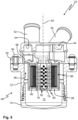
Fig. 5 shows an inertial separator for a brake dust filter system according to the invention, in a schematic sectional view, wherein the inertial separator comprises a nozzle structure and a baffle structure. -
Fig. 6 shows the inertial separator ofFig. 5 in a schematic perspective view, wherein a cover of a particle collection chamber has been removed. -
Figure 1 shows a brakedust filter system 10 arranged at two-wheel brake assemblies 12, which are disk brakes in the depicted embodiment. Thewheel brake assemblies 12 are part of a vehicle having wheels, such as a passenger car (not depicted). Thewheel brake assemblies 12 each comprise abrake disk 14 and acaliper 16 engaging around the associatedbrake disk 14. - A
suction bracket 18 of the brakedust filter system 10 is attached to each of thebrake calipers 16 and engages around the associatedbrake disk 14. Eachsuction bracket 18 provides twosuction ports 20 arranged on either side of thebrake disk 14. Thesuction brackets 18 with thesuction ports 20 are arranged behind thebrake calipers 16 with respect to a usual direction of rotation of the brake disk 14 (vehicle traveling forward). - The brake
dust filter system 10 further comprises aninertial separator 22, aparticle filter element 24 and anairflow generation device 26. Aduct arrangement 28 comprisingseveral air ducts suction brackets 18 to theinertial separator 22 and theinertial separator 22 to thepartricle filter element 24. - In the depicted embodiment, the
airflow generation device 26 is contained in afilter housing 34 of theparticle filter element 24, see alsoFigure 2 . Thefilter housing 34 has adetachable housing cover 35, to which theairflow generation device 26 is attached. Theairflow generation device 26, here a scution pump, is arranged downstream of theparticle filter element 24. - In this embodiment, the
filter housing 34 has twoconnection ports 36 which each receive one of theair ducts 32, which lead pre-cleaned air from theinertial separator 22 to theparticle filter element 24. - In the depicted embodiment, the
particle filter element 24 comprises a coarse filtermedium body 38, for instance a foam body, and a fine filtermedium body 40, for instance made from pleated filter paper. Thefilter media bodies body 38 upstream of the fine filtermedium body 40. - Purified air is released into the environment through a
clean air outlet 42, which is arranged downstream of theparticle filter element 24 and theairflow generation device 26. -
Figures 3 and4 show theinertial separator 22 in an enlarged side view or sectional view, respectively. - A
raw air inlet 44 is provided at the center of anupper side 46 of aseparator housing 48. In this embodiment, theraw air inlet 44 comprises twoinlet ports 50 each for connecting one of theair ducts 30 coming from thesuction ports 20. - In the depicted embodiment, the two
air ducts 32 leading to theparticle filter element 24 are each connected to anoutlet port 52. Eachoutlet port 52 defines anair outlet 54 for the airflow, form which in particular large particles have been removed in theinertial separator 22. Bothair outlets 54 are in fluidic communication with anannular outlet chamber 56 at top of theseparator housing 48, cf.Figure 4 . Theoutlet chamber 56 is arranged just below theupper side 46 of theseparator housing 48 with theoutlet ports 52 protruding from theupper side 46. - In the embodiment of
Figures 3 and4 , theinertial separator 22 comprises several, here six,cyclone separators 58. The cyclone separators 58 are arranged around theraw air inlet 44 with respect to a central (vertical)axis 60 of theseparator housing 48. For each of thecyclone separators 58, at least oneflow window 62 provides fluid communication to theraw air inlet 44, seeFigure 4 . - The raw airflow from the
suction ports 20 enters thecyclone separators 58 in a basically tangential direction with respect to anaxis 64 of a downwardly taperedcyclone chamber 66 of thecyclone separators 58. A spiral downward oriented flow pattern evolves in eachcyclone separator 58. Especially heavy brake dust particles are pressed aigainst the walls of thecyclone chambers 66, which results in deceleration of the particles. For eachcyclone separator 58, aparticle outlet 68 is provided at a lower end of therespective cyclone chamber 66. Under the influence of gravity, the particles will fall through theparticle outlets 68 into a commonparticle collection chamber 70. The purified air rises in a central region of thecyclone chambers 66, enters theannular outlet chamber 56 and is sucked towards the particle filter element 24 (seeFigures 1 and 2 ) by theairflow generation device 26. - The
particle collection chamber 70 is formed in theseparator housing 48 and is arranged below thecyclone separators 58. In the depicted embodiment, theseparator housing 48 comprises ahousing body 72 and acover 74. Mating threads are provided on thehousing body 72 and thecover 74. In the mounted state, thecover 74 closes theparticle collection chamber 70 at the bottom. When thecover 74 is unscrewed from thehousing body 72, theparticle collection chamber 70 can be emptied. -
Figures 5 and6 show an inertial separator 22', which can be used instead ofinertial separator 22 with the brakedust filter system 10 ofFigure 1 . - In the embodiment of
Figures 5 and6 , the raw airflow from thesuction ports 20 is fed into acenter pipe 76 through two raw air inlets 44 (one of which is visible inFigure 5 ; note that the inertial separator 22' is symmetrical to the section plane (drawing plane) ofFigure 5 ). Thecenter pipe 76 extends alongaxis 60 and is closed at itslower end 78. In this embodiment, thecenter pipe 76 has a hexagonal cross section, cf.Figure 6 . - The
center pipe 76 provides anozzle structure 80. Nozzle holes 82 are provided on side faces 84 of thecenter pipe 76. - A
baffle structure 86 surrounds thecenter pipe 76. In this embiment, thebaffle structure 86 comprises sixbaffle plates 88. Here, thebaffle structure 86 is designed as a cricumferentially closed baffle pipe with polygonal cross section, which baffle pipe surronds thecenter pipe 76. Thebaffle plates 88 are mounted or formed inside the baffle pipe. Eachbaffle plate 88 has a multitude ofspikes 90 facing towards thecenter pipe 76. - The raw airflow, which is fed into the
center pipe 76, is accelerated through the nozzle holes 82 towards thebaffle structure 86. Especially heavy brake dust particles will hit thebaffle plates 88 and are decelerated by contact with thespikes 90. An annularpariticle outlet 68 is formed between thecenter pipe 76 and thebaffle structure 86 at their lower ends. The particles fall through theparticle outlet 68 and are collected in aparticle collection chamber 70. - As in the embodiment of
Figures 3 and4 , theparticle collection chamber 70 is defined by acover 74, which is screwed to ahousing body 72 ofseparator housing 48. - An
upper housing part 92 may be fixed to thehousing body 72, e.g. by means ofbolts 94. Thenozzle structure 80 and thebaffle structure 86 are fixed to theupper housing part 92, e.g. glued or welded. - With inertial separator 22', the airflow is directed through the
particle outlet 68 into theparticle collection chamber 70. From theparticle collection chamber 70, the air containing less particles rises into anannular space 96, which is formed between the radially outer side of thebaffle structure 86 and the inner side of thehousing body 72. From theannular space 96, the pre-cleaned airflow enters into theupper housing part 92 at apassage 98, seeFigure 5 . From there, the airflow is sucked to theparticle filter element 24 through theair outlets 54, as described above. - In summary, the invention relates to an active brake dust filter system. An airflow containing brake dust particles is sucked into a duct arrangement by an airflow generation device. The airflow is first entered into an inertial separator. At least part of the brake dust particles, in particular a heavy fraction of the brake dust particles, is separated from the airflow in the inertial separator and expelled into a particle collection chamber. Secondly, the airflow containing less brake dust particles is led through a particle filter element to remove even more brake dust particles from the airflow. The cleaned airflow may be released into an environment. The ineratial separator reduces the amount of particles to be captured by the particle filter element. This allows to use a particle filter element capable of retaining even small brake dust particles while maintaining reasonably long service intervalls for exchanging the particle filter element. The particles collection chamber may be emptied during service.
-
- Brake
dust filter system 10 -
Wheel brake assemblie 12 -
Brake disk 14 -
Caliper 16 -
Suction bracket 18 -
Suction port 20 -
Inertial separator 22; 22' -
Particle filter element 24 -
Airflow generation device 26 -
Duct arrangement 28 -
Air ducts -
Filter housing 34 -
Housing cover 35 -
Connection ports 36 - Coarse filter
medium body 38 - Fine filter
medium body 40 -
Clean air outlet 42 -
Raw air inlet 44 -
Upper side 46 -
Separator housing 48 -
Inlet ports 50 -
Outlet port 52 -
Air outlet 54 -
Outlet chamber 56 -
Cyclone separators 58 -
Axis 60 of theseparator housing 48 -
Flow window 62 -
Axis 64 of a taperedcyclone chamber 66 -
Tapered cyclone chamber 66 -
Particle outlet 68 -
Particle collection chamber 70 -
Housing body 72 -
Cover 74 -
Center pipe 76 -
Lower end 78 -
Nozzle structure 80 - Nozzle holes 82
- Side faces 84
-
Baffle structure 86 -
Baffle plates 88 -
Spikes 90 -
Upper housing part 92 -
Bolts 94 -
Annular space 96 -
Passage 98
Claims (15)
- A brake dust filter system (10) for a vehicle, the brake dust filter system (10) comprising:at least one suction port (20) configured to be positioned near a wheel brake assembly (12) of the vehicle in an installed state of the brake dust filter system (10);a duct arrangement (28);an airflow generation device (26) configured to generate an airflow from the at least one suction port (20) through the duct arrangement (28) towards the airflow generation device (26);a particle filter element (24) fluidically coupled to the duct arrangement (28) and arranged downstream of the at least one suction port (20); andan inertial separator (22; 22') fluidically coupled to the duct arrangement (28) and arranged upstream of the particle filter element (24) and downstream of the at least one suction port (20), the inertial separator (22; 22') comprising:a raw air inlet (44) for the airflow from the at least one suction port (20);at least one particle outlet (68) for particles that are separated from the airflow by the inertial separator (22; 22'); andat least one air outlet (54) for the airflow towards the particle filter element (24),wherein the particle outlet (68) is connected to a particle collection chamber (70).
- The brake dust filter system (10) according to claim 1, wherein the particle collection chamber (70) is arranged below the inertial separator (22; 22').
- The brake dust filter system (10) according to one of the preceding claims, wherein the inertial separator (22; 22') is received in a separator housing (48), and
the separator housing (48) comprises the raw air inlet (44) and the at least one air outlet (54). - The brake dust filter system (10) according to claim 3, wherein the separator housing (48) comprises a detachable cover (74) for the particle collection chamber (70).
- The brake dust filter system (10) according claim 3 or 4, wherein the raw air inlet (44) and the at least one air outlet (54) are comprised at an upper side (46) of the separator housing (48).
- The brake dust filter system (10) according to one of the preceding claims, wherein the airflow generation device (26) is arranged downstream of the particle filter element (24).
- The brake dust filter system (10) according to one of the preceding claims, wherein the particle filter element (24) comprises a coarse filter medium body (38) and a fine filter medium body (40) arranged downstream of the coarse filter medium body (38).
- The brake dust filter system (10) according to one of the preceding claims, wherein the particle filter element (24) is received in a filter housing (34), and
the filter housing (34) comprises at least one connection port (36) coupled to the duct arrangement (28). - The brake dust filter system (10) according to one of the preceding claims, wherein the at least one suction port (20) is arranged at a suction bracket (18) at least partially engaging around a brake disk (14).
- The brake dust filter system (10) according to one of the preceding claims, wherein the inertial separator (22) comprises at least one cyclone separator (58).
- The brake dust filter system (10) according to claim 10, wherein the raw air inlet (44) is fluidically coupled to multiple cyclone separators (58) through multiple flow windows (62), and
the multiple cyclone separators (58) are arranged around the raw air inlet (44). - The brake dust filter system (10) according to one of the preceding claims, wherein the inertial separator (22') comprises a nozzle structure (80) fluidically coupled to the raw air inlet (44), and at least one baffle structure (86) arranged to be encountered by the airflow after passing through the nozzle structure (80).
- The brake dust filter system (10) according to claim 12, wherein the nozzle structure (80) comprises a center pipe (76) with radially oriented nozzle holes (82).
- The brake dust filter system (10) according to claim 13, wherein the at least one baffle structure (86) surrounds the center pipe (76).
- The brake dust filter system (10) according to one of claims 12 to 14, wherein the at least one baffle structure (86) comprises spikes (90) facing towards the nozzle structure (80).
Priority Applications (1)
| Application Number | Priority Date | Filing Date | Title |
|---|---|---|---|
| EP23195574.1A EP4520994B1 (en) | 2023-09-06 | 2023-09-06 | Brake dust filter system |
Applications Claiming Priority (1)
| Application Number | Priority Date | Filing Date | Title |
|---|---|---|---|
| EP23195574.1A EP4520994B1 (en) | 2023-09-06 | 2023-09-06 | Brake dust filter system |
Publications (2)
| Publication Number | Publication Date |
|---|---|
| EP4520994A1 true EP4520994A1 (en) | 2025-03-12 |
| EP4520994B1 EP4520994B1 (en) | 2026-04-08 |
Family
ID=87933542
Family Applications (1)
| Application Number | Title | Priority Date | Filing Date |
|---|---|---|---|
| EP23195574.1A Active EP4520994B1 (en) | 2023-09-06 | 2023-09-06 | Brake dust filter system |
Country Status (1)
| Country | Link |
|---|---|
| EP (1) | EP4520994B1 (en) |
Citations (7)
| Publication number | Priority date | Publication date | Assignee | Title |
|---|---|---|---|---|
| US20100139033A1 (en) * | 2007-12-06 | 2010-06-10 | Sergey Makarov | Dual Stage Cyclonic Dust Collector |
| EP2084423B1 (en) | 2006-10-27 | 2010-07-14 | Mann + Hummel GmbH | Filter arrangement for brake-dust retaining systems |
| US20130105252A1 (en) * | 2010-06-24 | 2013-05-02 | Knorr-Bremse Systeme Fuer Nutzfahrzeuge Gmbh | Disc Brake |
| CN103511137A (en) * | 2013-10-08 | 2014-01-15 | 潍柴动力股份有限公司 | Desert air filter and vehicle with same |
| US9726241B2 (en) | 2012-11-08 | 2017-08-08 | Tallano Technologie | Brake assembly with particle capture |
| US20200355230A1 (en) * | 2017-11-06 | 2020-11-12 | Sogefi Filtration | Filtration device and use of said device for separating and collecting brake dust |
| US20220252117A1 (en) * | 2019-03-11 | 2022-08-11 | Sogefi Filtration | Separating device and use of the device for separating and collecting brake dust |
-
2023
- 2023-09-06 EP EP23195574.1A patent/EP4520994B1/en active Active
Patent Citations (8)
| Publication number | Priority date | Publication date | Assignee | Title |
|---|---|---|---|---|
| EP2084423B1 (en) | 2006-10-27 | 2010-07-14 | Mann + Hummel GmbH | Filter arrangement for brake-dust retaining systems |
| US20100139033A1 (en) * | 2007-12-06 | 2010-06-10 | Sergey Makarov | Dual Stage Cyclonic Dust Collector |
| US20130105252A1 (en) * | 2010-06-24 | 2013-05-02 | Knorr-Bremse Systeme Fuer Nutzfahrzeuge Gmbh | Disc Brake |
| EP2585730B1 (en) | 2010-06-24 | 2016-01-13 | KNORR-BREMSE Systeme für Nutzfahrzeuge GmbH | Disc brake |
| US9726241B2 (en) | 2012-11-08 | 2017-08-08 | Tallano Technologie | Brake assembly with particle capture |
| CN103511137A (en) * | 2013-10-08 | 2014-01-15 | 潍柴动力股份有限公司 | Desert air filter and vehicle with same |
| US20200355230A1 (en) * | 2017-11-06 | 2020-11-12 | Sogefi Filtration | Filtration device and use of said device for separating and collecting brake dust |
| US20220252117A1 (en) * | 2019-03-11 | 2022-08-11 | Sogefi Filtration | Separating device and use of the device for separating and collecting brake dust |
Also Published As
| Publication number | Publication date |
|---|---|
| EP4520994B1 (en) | 2026-04-08 |
Similar Documents
| Publication | Publication Date | Title |
|---|---|---|
| CN113613973B (en) | Separating device and use of a device for separating and collecting brake dust | |
| JP7336103B2 (en) | Filtration device and its use for separating and collecting brake dust | |
| US4832709A (en) | Rotary separator with a bladeless intermediate portion | |
| US20140054121A1 (en) | Brake Dust Collector for Motor Vehicles | |
| EP1268038B1 (en) | Intake air cleaning apparatus | |
| US20220397168A1 (en) | Brake Dust Particle Filter, Disc Brake Assembly, Use of a Filter, and Method for Filtering Air Laden with Brake Dust | |
| CN108386464A (en) | Device for absorption brake dust particles and the motor vehicles with disk brake | |
| US11420137B2 (en) | Effluent processing apparatus for a vehicle air brake charging system | |
| KR102631279B1 (en) | Dust collecting apparatus for brake of vehicle | |
| KR20190045437A (en) | Dust collector installed at wheel of vehicle | |
| EP4520994B1 (en) | Brake dust filter system | |
| GB2199267A (en) | A gas separating apparatus | |
| EP0122795B1 (en) | Filter for removing particulates suspended in a fluid, e.g. gaseous medium | |
| CN212508590U (en) | Multi-unit air filtering device | |
| CN116174153A (en) | Industrial environment-friendly dust remover | |
| EP4570349A1 (en) | Air filter having particle collection chamber for pre-separated particles inside filter element | |
| EP4570348A1 (en) | Air filter having particle collection chamber for pre-separated particles inside filter element | |
| EP4379229B1 (en) | A brake air through flow and brake dust collector system for a brake installation, vehicle brake system and method for purifying brake air from a vehicle brake system | |
| US20220401968A1 (en) | Multicyclone separator | |
| EP4414579A1 (en) | Disc brake assembly and brake dust particle filter (bdpf) for active suction due to inner ventilation | |
| KR102959461B1 (en) | Dust removal system for drum brake | |
| JP2025513236A (en) | Apparatus for trapping liquid particles in a gas stream | |
| KR102772616B1 (en) | Dust collecting apparatus for vehicle | |
| CN114251204B (en) | Multi-unit air filtering device | |
| CN211358173U (en) | Special dust collector for railway track grinding wagon |
Legal Events
| Date | Code | Title | Description |
|---|---|---|---|
| PUAI | Public reference made under article 153(3) epc to a published international application that has entered the european phase |
Free format text: ORIGINAL CODE: 0009012 |
|
| STAA | Information on the status of an ep patent application or granted ep patent |
Free format text: STATUS: THE APPLICATION HAS BEEN PUBLISHED |
|
| AK | Designated contracting states |
Kind code of ref document: A1 Designated state(s): AL AT BE BG CH CY CZ DE DK EE ES FI FR GB GR HR HU IE IS IT LI LT LU LV MC ME MK MT NL NO PL PT RO RS SE SI SK SM TR |
|
| STAA | Information on the status of an ep patent application or granted ep patent |
Free format text: STATUS: REQUEST FOR EXAMINATION WAS MADE |
|
| 17P | Request for examination filed |
Effective date: 20250825 |
|
| GRAP | Despatch of communication of intention to grant a patent |
Free format text: ORIGINAL CODE: EPIDOSNIGR1 |
|
| STAA | Information on the status of an ep patent application or granted ep patent |
Free format text: STATUS: GRANT OF PATENT IS INTENDED |
|
| RIC1 | Information provided on ipc code assigned before grant |
Ipc: F16D 65/00 20060101AFI20251008BHEP |
|
| INTG | Intention to grant announced |
Effective date: 20251027 |
|
| GRAS | Grant fee paid |
Free format text: ORIGINAL CODE: EPIDOSNIGR3 |
|
| GRAA | (expected) grant |
Free format text: ORIGINAL CODE: 0009210 |
|
| STAA | Information on the status of an ep patent application or granted ep patent |
Free format text: STATUS: THE PATENT HAS BEEN GRANTED |
|
| AK | Designated contracting states |
Kind code of ref document: B1 Designated state(s): AL AT BE BG CH CY CZ DE DK EE ES FI FR GB GR HR HU IE IS IT LI LT LU LV MC ME MK MT NL NO PL PT RO RS SE SI SK SM TR |
|
| REG | Reference to a national code |
Ref country code: CH Ref legal event code: F10 Free format text: ST27 STATUS EVENT CODE: U-0-0-F10-F00 (AS PROVIDED BY THE NATIONAL OFFICE) Effective date: 20260408 Ref country code: GB Ref legal event code: FG4D |
|
| REG | Reference to a national code |
Ref country code: DE Ref legal event code: R096 Ref document number: 602023014781 Country of ref document: DE |
|
| REG | Reference to a national code |
Ref country code: IE Ref legal event code: FG4D |