EP4520993A1 - Speed control device and vehicle - Google Patents
Speed control device and vehicle Download PDFInfo
- Publication number
- EP4520993A1 EP4520993A1 EP24197874.1A EP24197874A EP4520993A1 EP 4520993 A1 EP4520993 A1 EP 4520993A1 EP 24197874 A EP24197874 A EP 24197874A EP 4520993 A1 EP4520993 A1 EP 4520993A1
- Authority
- EP
- European Patent Office
- Prior art keywords
- shift cam
- control device
- speed control
- wheel
- vehicle
- Prior art date
- Legal status (The legal status is an assumption and is not a legal conclusion. Google has not performed a legal analysis and makes no representation as to the accuracy of the status listed.)
- Pending
Links
Images






Classifications
-
- F—MECHANICAL ENGINEERING; LIGHTING; HEATING; WEAPONS; BLASTING
- F16—ENGINEERING ELEMENTS AND UNITS; GENERAL MEASURES FOR PRODUCING AND MAINTAINING EFFECTIVE FUNCTIONING OF MACHINES OR INSTALLATIONS; THERMAL INSULATION IN GENERAL
- F16D—COUPLINGS FOR TRANSMITTING ROTATION; CLUTCHES; BRAKES
- F16D59/00—Self-acting brakes, e.g. coming into operation at a predetermined speed
-
- B—PERFORMING OPERATIONS; TRANSPORTING
- B60—VEHICLES IN GENERAL
- B60B—VEHICLE WHEELS; CASTORS; AXLES FOR WHEELS OR CASTORS; INCREASING WHEEL ADHESION
- B60B33/00—Castors in general ; Anti-clogging castors
- B60B33/0078—Castors in general ; Anti-clogging castors characterised by details of the wheel braking mechanism
-
- B—PERFORMING OPERATIONS; TRANSPORTING
- B60—VEHICLES IN GENERAL
- B60B—VEHICLE WHEELS; CASTORS; AXLES FOR WHEELS OR CASTORS; INCREASING WHEEL ADHESION
- B60B33/00—Castors in general ; Anti-clogging castors
- B60B33/0078—Castors in general ; Anti-clogging castors characterised by details of the wheel braking mechanism
- B60B33/0084—Castors in general ; Anti-clogging castors characterised by details of the wheel braking mechanism acting on axle end
-
- B—PERFORMING OPERATIONS; TRANSPORTING
- B62—LAND VEHICLES FOR TRAVELLING OTHERWISE THAN ON RAILS
- B62B—HAND-PROPELLED VEHICLES, e.g. HAND CARTS OR PERAMBULATORS; SLEDGES
- B62B3/00—Hand carts having more than one axis carrying transport wheels; Steering devices therefor; Equipment therefor
-
- B—PERFORMING OPERATIONS; TRANSPORTING
- B62—LAND VEHICLES FOR TRAVELLING OTHERWISE THAN ON RAILS
- B62B—HAND-PROPELLED VEHICLES, e.g. HAND CARTS OR PERAMBULATORS; SLEDGES
- B62B5/00—Accessories or details specially adapted for hand carts
- B62B5/002—Adaptations for moving the carts by wheel chair users or other disabled persons
-
- B—PERFORMING OPERATIONS; TRANSPORTING
- B62—LAND VEHICLES FOR TRAVELLING OTHERWISE THAN ON RAILS
- B62B—HAND-PROPELLED VEHICLES, e.g. HAND CARTS OR PERAMBULATORS; SLEDGES
- B62B5/00—Accessories or details specially adapted for hand carts
- B62B5/04—Braking mechanisms; Locking devices against movement
- B62B5/048—Hub brakes; drum brakes
-
- B—PERFORMING OPERATIONS; TRANSPORTING
- B62—LAND VEHICLES FOR TRAVELLING OTHERWISE THAN ON RAILS
- B62B—HAND-PROPELLED VEHICLES, e.g. HAND CARTS OR PERAMBULATORS; SLEDGES
- B62B9/00—Accessories or details specially adapted for children's carriages or perambulators
- B62B9/08—Braking mechanisms; Locking devices against movement
-
- F—MECHANICAL ENGINEERING; LIGHTING; HEATING; WEAPONS; BLASTING
- F16—ENGINEERING ELEMENTS AND UNITS; GENERAL MEASURES FOR PRODUCING AND MAINTAINING EFFECTIVE FUNCTIONING OF MACHINES OR INSTALLATIONS; THERMAL INSULATION IN GENERAL
- F16D—COUPLINGS FOR TRANSMITTING ROTATION; CLUTCHES; BRAKES
- F16D2127/00—Auxiliary mechanisms
- F16D2127/001—Auxiliary mechanisms for automatic or self-acting brake operation
- F16D2127/002—Auxiliary mechanisms for automatic or self-acting brake operation speed-responsive
Definitions
- the present invention relates to a speed control device and a vehicle.
- a vehicle such as a rollator used to assist a user in walking may be equipped with a speed control device for controlling the rotation speed of a vehicle wheel (see, for example, Patent Literature 1).
- the speed control device is installed on a vehicle wheel.
- the speed control device includes, for example, a brake drum, a brake shoe, an elastic member, a contact member, a cam, and an adjustment gear.
- the brake shoe contacts the inner circumferential surface of the brake drum.
- the elastic member biases the brake shoe.
- the cam applies a force in the compressive direction to the elastic member via the contact member.
- the adjustment gear sets the position of the cam in the rotational direction to adjust the force with which the contact member presses the elastic member.
- Patent Literature 1 Japanese Patent Application Publication No. 2022-59838
- a larger adjustment range of braking force is being considered for the speed control device. If the adjustment range of the braking force can be larger, it is possible, for example, to apply the braking force during high speed traveling. However, in the structure of conventional speed control devices, it was difficult to enlarge the adjustment range of braking force.
- One aspect of the present invention provides a speed control device and a vehicle capable of enlarging the adjustment range of braking force.
- a speed control device is a speed control device provided on a vehicle wheel rotating around a rotation axis so as to control rotation speed of the vehicle wheel, the speed control device comprising: a brake drum; a brake shoe for reducing the rotation speed of the vehicle wheel by a braking force produced by contact with an inner circumference of the brake drum; an elastic member having one end and another end, the elastic member being configured to bias the brake shoe via the one end; a contact member provided on the other end of the elastic member; a shift cam provided so as to be rotatable around the rotation axis and configured to increase or reduce a force of the contact member pressing the elastic member in accordance with a rotational position of the shift cam; and an adjustment gear operated by an external input to rotate the shift cam, so as to set the rotational position of the shift cam to adjust the force pressing the elastic member.
- the shift cam has a larger diameter than the adjustment gear.
- the outer diameter of the shift cam is larger than the outer diameter of the adjustment gear, allowing for a larger adjustment range of the braking force. This also allows for a greater degree of freedom in setting the braking force.
- the braking force can be set such that it is applied during traveling at a higher speed than it was before.
- the speed control device may further comprise a cover plate covering at least the shift cam.
- the cover plate may have at least one window formed therein for indicating the rotational position of the shift cam.
- the window can indicate the braking force of the centrifugal brake so that it can be grasped easily. Therefore, works such as setting of the rotation speed of the vehicle wheel on which the centrifugal brake is activated can be easily performed.
- the at least one window may comprise a plurality of windows.
- the plurality of windows may be located at different positions along a rotational direction of the shift cam, and a number of windows overlapping the shift cam may change in accordance with the rotational position of the shift cam. In this case, it is possible to indicate the braking force of the centrifugal brake so that it can be grasped more easily.
- the shift cam may have a position indicator for indicating the rotational position of the shift cam.
- the at least one window may be formed such that the position indicator is visible. In this case, it is possible to indicate the braking force of the centrifugal brake so that it can be grasped more easily.
- a vehicle according to one aspect of the invention comprises: the speed control device described above; and a vehicle wheel having the speed control device provided thereon. Since the vehicle is equipped with the speed control device, the adjustment range of the braking force can be larger. This allows for a greater degree of freedom in setting the braking force.
- One aspect of the present invention makes is possible to enlarge the adjustment range of braking force.
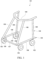
- Fig. 1 is a schematic diagram of a rollator 101, or a vehicle according to an embodiment.
- the rollator 101 is used, for example, to assist a user in walking.
- the vertical direction is defined as it is when the rollator 101 is used.
- the front direction is defined as the traveling direction of the rollator 101 being used, and the rear direction is defined as the opposite to the traveling direction.
- the vehicle width direction of the rollator 101 is defined as the direction orthogonal to the vertical direction and the front-rear direction.
- the rollator 101 includes a body 102, a plurality of vehicle wheels 103, and a handling portion 104.
- the body 102 includes a lower frame 105 and a plurality of vertical frames 106.
- the lower frame 105 includes a front frame 107 and two side frames 108.
- the side frames 108 extend rearward from the ends of the front frame 107.
- the plurality of vertical frames 106 extend upward from the front and rear of the side frames 108.
- the vehicle wheels 103 are located at the front and rear of the side frames 108.
- the handling portion 104 is U-shaped.
- the handling portion 104 is connected to the upper ends of the vertical frames 106.
- the rollator 101 travels as the user pushes the handling portion 104 with his or her hand.
- the rollator 101 is an example of the vehicle.
- the vehicle is not limited to a rollator, but can also be, for example, a cart for transporting luggage or a buggy for carrying an infant.
- Fig. 2 is an exploded perspective view of a speed control device 1 and a vehicle wheel 103 according to a first embodiment.
- Fig. 3 is a plan view showing a centrifugal brake unit 13 included in the speed control device 1.
- Fig. 4 is a plan view showing a cover plate 28 included in the speed control device 1.
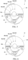
- Figs. 5 to 8 are plan views each showing a part of the speed control device 1.
- the vehicle wheels 103 are mounted on brackets 109 provided at the lower portions of the front and rear of the side frames 108.
- the vehicle wheels 103 are thus secured to the body 102 via the brackets 109.
- the plurality of vehicle wheels 103 provided on the body 102 are configured in the same manner. Therefore, only one of the vehicle wheels 103 will be hereinafter described, and the other vehicle wheels 103 will not be described.
- the vehicle wheel 103 includes an axle 21 supported by the bracket 109, a disc-shaped wheel 50 rotatably supported by the axle 21, and a tire 51 mounted on the outer circumference of the wheel 50.
- the axle 21 protrudes from the bracket 109 toward the outside in the vehicle width direction.
- the axle 21 is positioned so that the axial direction of the axle 21 coincides with the vehicle width direction.
- the central axis that extends through the center of the axle 21 in the vehicle width direction is the rotation axis 20.
- the vehicle wheel 103 rotates around the rotation axis 20.
- the directions intersecting the rotation axis 20 are defined as the radial directions
- the direction circling around the rotation axis 20 is defined as the circumferential direction.
- the wheel 50 includes a first wheel plate 60 and a second wheel plate 70 that overlap in the axial direction of the axle 21.
- the first wheel plate 60 and the second wheel plate 70 have a disc-like outer shape and are rotatably supported by the axle 21.
- the first wheel plate 60 is located closer to the bracket 109 than is the second wheel plate 70.
- the first wheel plate 60 includes a first housing portion 61 having a bottomed cylindrical shape and opening toward the second wheel plate 70, a first rim 62 having a cylindrical shape and positioned to surround the first housing portion 61 externally in the radial direction, and a plurality of first spokes 63 connecting the first housing portion 61 and the first rim 62 in the radial direction.
- the first housing portion 61 includes a first bottom wall 61a having a disc-like shape and a first circumferential wall 61b that protrudes from the outer edge of the first bottom wall 61a toward the second wheel plate 70 and extends all along the outer edge of the first bottom wall 61a.
- the inner space of the first housing portion 61 serves as a first housing space R1, which is open toward the second wheel plate 70.
- the first bottom wall 61a includes a bearing housing 64 that houses a bearing (not shown).
- the bearing housing 64 is positioned coaxially with the rotation axis 20 and formed cylindrically to protrude inward in the vehicle width direction. The first wheel plate 60 is thus rotatably supported by the axle 21 via the bearing housed in the bearing housing 64.
- first bottom wall 61a has a plurality of first planetary support pins 65 integrally formed thereon.
- first planetary support pins 65 are formed at regular intervals in the circumferential direction around the rotation axis 20.
- the first planetary support pins 65 are formed to protrude from the first bottom wall 61a toward the second wheel plate 70.
- the first planetary support pins 65 constitute a part of the speed control device 1.
- Three first spokes 63 are formed at regular intervals in the circumferential direction around the rotation axis 20.
- the first spokes 63 are formed to extend radially outward from the outer circumference of the first circumferential wall 61b and is connected to the inner circumference of the first rim 62.
- the first spokes 63 are formed so that their circumferential width along the circumferential direction is gradually smaller toward the radially outward direction.
- the number and shape of the first spokes 63 are not limited to these, but may be changed as needed.
- the first spokes 63 each have a bolt insertion hole 63a that extends through the first spokes 63 in the vehicle width direction.
- the second housing portion 71 includes a second bottom wall 71a having a disc-like shape and a second circumferential wall 71b that protrudes from the outer edge of the second bottom wall 71a toward the first wheel plate 60 and extends all along the outer edge of the second bottom wall 71a.
- the inner space of the second housing portion 71 serves as a second housing space (not shown), which is open toward the first wheel plate 60.
- the second bottom wall 71a has an opening 19 that extends through the second bottom wall 71a in the vehicle width direction.
- the opening 19 serves as a viewing window for externally viewing a window 40 of the cover plate 28, which will be described later.
- the second bottom wall 71a has a cover mounting portion 75 integrally formed thereon.
- the cover mounting portion 75 has a cylindrical shape and protrudes outward in the vehicle width direction.
- the opening 19 is positioned inside the cover mounting portion 75.
- the second housing portion 71 configured as described above, is formed in a bottomed cylindrical shape having the same outer diameter as the first housing portion 61.
- the second housing portion 71 is opposed to the first housing portion 61 from the outside in the vehicle width direction.
- Three second spokes 73 are formed at regular intervals in the circumferential direction around the rotation axis 20.
- the second spokes 73 are formed to extend radially outward from the outer circumference of the second circumferential wall 71b and is connected to the inner circumference of the second rim 72.
- the second spokes 73 are formed so that their circumferential width along the circumferential direction is gradually smaller toward the radially outward direction.
- the second spokes 73 are formed in the same number, shape, size, etc. as the first spokes 63, and are opposed to the first spokes 63 from the outside in the vehicle width direction.
- the second spokes 73 each have a bolt hole (threaded hole) (not shown) that is open toward the inside in the vehicle width direction.
- the bolt holes are opposed in the vehicle width direction to the bolt insertion holes 63a formed in the first spokes 63.
- the first wheel plate 60 and the second wheel plate 70 coaxially overlap with each other and are fastened together by bolts (not shown).
- the first wheel plate 60 and the second wheel plate 70 are integrated together to constitute the wheel 50.
- the bolts are screwed into the bolt holes from the inside in the vehicle width direction through the bolt insertion holes 63a.
- the first wheel plate 60 and the second wheel plate 70 are assembled together so that the opening of the first housing space R1 and the opening of the second housing space overlap with each other.
- an inner housing space R is formed inside the wheel 50 by the first housing space R1 and the second housing space.
- the first wheel plate 60 and the second wheel plate 70 are assembled together so that the first spokes 63 and the second spokes 73 are assembled together to serve as spokes 55.
- the tire 51 is integrally formed to surround the wheel 50 externally in the radial direction, the wheel 50 being constituted by the first wheel plate 60 and the second wheel plate 70 assembled together. Specifically, the tire 51 is assembled to the wheel 50 with its inner circumference in contact with the outer circumference of the wheel 50 (the outer circumference of the first rim 62 in the first wheel plate 60 and the outer circumference of the second rim 72 in the second wheel plate 70) from the outside in the radial direction.
- the speed control device 1 is positioned in the inner housing space R of the wheel 50 described above.
- the speed control device 1 includes a planetary gear mechanism 80, an internal gear 90, a brake drum 11, a centrifugal brake unit 13, and a cap 15.
- the planetary gear mechanism 80 has a two-stage configuration and is mainly located in the first housing space R1 of the first wheel plate 60.
- the planetary gear mechanism 80 includes a first-stage gear mechanism 110 and a second-stage gear mechanism 120.
- the first-stage gear mechanism 110 is located on the first bottom wall 61a of the first housing portion 61
- the second-stage gear mechanism 120 is located on the outer side of the first-stage gear mechanism 110 in the vehicle width direction.
- the first-stage gear mechanism 110 includes a first sun gear (not shown) rotatably supported on the axle 21, and a plurality of first planetary gears 111 arranged around the first sun gear.
- the first sun gear is formed integrally with a second planetary carrier 122, which will be described later.
- Three first planetary gears 111 are arranged at regular intervals in the circumferential direction around the rotation axis 20 and are each meshed with the first sun gear.
- the first planetary gears 111 are rotatably supported by the first planetary support pins 65 integrally formed on the first bottom wall 61a of the first housing portion 61.
- the first bottom wall 61a serves as a planetary carrier that rotatably supports the plurality of first planetary gears 111.
- the second-stage gear mechanism 120 includes a second sun gear (not shown) rotatably supported on the axle 21, a plurality of second planetary gears 121 arranged around the second sun gear, and a second planetary carrier 122 that rotatably supports the plurality of second planetary gears 121.
- the second sun gear is formed integrally with a support plate 29 (described later) included in the centrifugal brake unit 13, and is positioned in line with the first sun gear in the vehicle width direction.
- the second planetary carrier 122 includes a disc-shaped carrier plate 123 and second planetary support pins 124 protruding from the carrier plate 123 toward the outside in the vehicle width direction.
- the carrier plate 123 has the first sun gear formed thereon, protruding toward the inside in the vehicle width direction.
- Three second planetary support pins 124 are formed at regular intervals in the circumferential direction around the rotation axis 20, so as to correspond to the first planetary support pins 65.
- the second planetary support pins 124 constitute a part of the speed control device 2.
- Three second planetary gears 121 are arranged at regular intervals in the circumferential direction around the rotation axis 20 and are each meshed with the second sun gear.
- the second planetary gears 121 are rotatably supported by the second planetary support pins 124 formed on the second planetary carrier 122.
- the internal gear 90 is formed in a cylindrical shape surrounding the first planetary gears 111 of the first-stage gear mechanism 110 and the second planetary gears 121 of the second-stage gear mechanism 120.
- the internal gear 90 has internal teeth continuously formed on the entire inner circumference.
- the internal gear meshes with the first planetary gears 111 and the second planetary gears 121.
- the brake drum 11 is positioned on the outer side of the internal gear 90 in the vehicle width direction.
- the brake drum 11 is formed in a bottomed cylindrical shape including a cylindrical portion 11a and a bottom portion 11b, with the opening facing inward (toward the internal gear 90) in the vehicle width direction.
- the cylindrical portion 11a of the brake drum 11 surrounds the internal gear 90 externally in the radial direction.
- the inner circumference of the cylindrical portion 11a is fitted on the outer circumference of the internal gear 90.
- a through hole (not shown) is formed in the middle of the bottom portion 11b, to extend through the bottom portion 11b in the vehicle width direction.
- the through hole is coaxial with the rotation axis 20.
- the through hole receives a bush provided on the axle 21 for example, and press-fitted in the through hole.
- the brake drum 11 is integrally fixed to the axle 21. Therefore, the internal gear 90 is integrally fixed to the axle 21 via the brake drum 11.
- the bottom portion 11b has a plurality of operation windows 11c that extend through the bottom portion 11b in the vehicle width direction. This arrangement allows communication between the outside of the vehicle wheel 103 and the inside of the brake drum 11 through the operation windows 11c and the opening 19 formed in the second wheel plate 70.
- the cap 15 is removably attached to the cover mounting portion 75 of the second wheel plate 70. Thus, the cap 15 normally covers the opening 19.
- the centrifugal brake unit 13 is positioned on the inner side of the brake drum 11, while being positioned on the outer side of the planetary gear mechanism 80 in the vehicle width direction. Specifically, the centrifugal brake unit 13 is positioned between the second-stage gear mechanism 120 and the bottom portion 11b of the brake drum 11, and is located inside the cylindrical portion 11a of the brake drum 11.
- the centrifugal brake unit 13 is a mechanism for generating a braking force of the centrifugal brake between the centrifugal brake unit 13 and the brake drum 11.
- the centrifugal brake unit 13 is rotatable around the rotation axis 20.
- the centrifugal brake unit 13 includes two brake shoes 23, two springs 24 (elastic members), two contact members 25, a shift cam 26, two adjustment gears 27, a cover plate 28, and a support plate 29.
- Fig. 3 does not show the axle 21.
- each of the brake shoes 23 is shaped like a long plate extending along the circumferential direction around the rotation axis 20.
- the brake shoe 23 is rotatably supported by the support plate 29 via a rotating shaft 31.
- the rotating shaft 31 is located at a position off the longitudinally middle portion of the brake shoe 23 toward one end of the brake shoe 23.
- the one end of the brake shoe 23 is biased by the spring 24 outward in the radial direction of the support plate 29.
- the two brake shoes 23 are positioned opposite to each other in the radial direction of the support plate 29, with the center of the support plate 29 (rotation axis 20) interposed therebetween.
- the brake shoes 23 shown in Fig. 2 and the brake shoes 23 shown in Fig. 3 use different rotating shafts 31 but have the same basic configuration and operation, with only the difference in rotational direction.
- Each of the brake shoes 23 has an outer peripheral surface that is curved along its longitudinal direction.
- a pad 30 is attached to the outer peripheral surface of the other end of the brake shoe 23.
- the pad 30 is provided on the opposite side to the one end at which the brake shoe 23 is biased by the spring 24, with the rotating shaft 31 positioned between the pad 30 and the one end.
- the brake shoe 23 rotates around the rotating shaft 31 to bring the pad 30 into contact with the inner circumference of the cylindrical portion 11a of the brake drum 11.
- the brake shoe 23 reduces the rotation speed of the vehicle wheel 103 by the braking force produced by contact with the inner circumference of the brake drum 11.
- the spring 24 is, for example, a coil spring, having one end and the other end.
- the spring 24 is provided between the one end of the brake shoe 23 and the contact member 25.
- the spring 24 extends along the radial direction of the support plate 29.
- the one end of the spring 24 is in contact with the one end of the brake shoe 23 and biases the one end of the brake shoe 23 outward in the radial direction of the support plate 29.
- the two springs 24 are positioned opposite to each other in the radial direction of the support plate 29, with the center of the support plate 29 (rotation axis 20) interposed therebetween.
- the spring 24 restricts the contact between the brake drum 11 and the brake shoe 23, resulting in a smaller braking force.
- the spring 24 allows contact between the brake drum 11 and the brake shoe 23, resulting in a larger braking force.
- the spring 24 is covered by a protective cover 22 attached to the support plate 29.
- the protective cover 22 which prevents dust and other particles from adhering to the spring 24.
- Fig. 2 shows the protective cover 22 covering the spring 24.
- Each of the contact members 25 is provided at the other end of the spring 24 (the part opposite to the one end).
- the two contact members 25 are positioned opposite to each other in the radial direction of the support plate 29, with the center of the support plate 29 (rotation axis 20) interposed therebetween.
- the contact members 25 are movable along the direction of expansion and contraction of the spring 24.
- the shift cam 26 is mounted to the support plate 29 so as to be rotatable around the rotation axis 20.
- the shift cam 26 is in direct or indirect contact with the contact members 25.
- the shift cam 26 increases or reduces the force with which the contact members 25 press the springs 24.
- the shift cam 26 has two meshing portions 32 at two locations on its outer edge.
- the meshing portions 32 have a plurality of teeth 32a.
- the two meshing portions 32 are positioned opposite to each other in the radial direction of the support plate 29, with the center of the shift cam 26 (rotation axis 20) interposed therebetween.
- the shift cam 26 has two cam portions 33 (drive portions) at two locations on its outer edge other than the meshing portions 32.
- Each of the cam portions 33 has a plurality of engagement steps 34 at different distances from the rotation axis 20.
- the plurality of engagement steps 34 include a first engagement step 34a, a second engagement step 34b, a third engagement step 34c, and a fourth engagement step 34d.
- the first engagement step 34a, the second engagement step 34b, the third engagement step 34c, and the fourth engagement step 34d are collectively referred to as "the engagement steps 34a to 34d".
- the second engagement step 34b is formed at a larger distance from the rotation axis 20 than the first engagement step 34a.
- the third engagement step 34c is formed at a larger distance from the rotation axis 20 than the second engagement step 34b.
- the fourth engagement step 34d is formed at a larger distance from the rotation axis 20 than the third engagement step 34c.
- the engagement steps 34a to 34d can engage with the contact member 25.
- the force of the spring 24 pressing the brake shoe 23 is slightly larger than when the contact member 25 engages with the first engagement step 34a. Therefore, the brake shoe 23 is allowed to rotate when subjected to a large centrifugal force. Therefore, when the rotation speed of the vehicle wheel 103 is relatively high, the brake shoe 23 contacts the inner circumference of the brake drum 11 to exert a braking force.
- the engagement steps 34a to 34d are provided along the circumferential direction around the center of the shift cam 26 (rotation axis 20) and are arranged in the circumferential direction in this order. Therefore, the cam portion 33 allows selection from the engagement steps 34a to 34d in accordance with the rotational position of the shift cam 26, thereby increasing or reducing the force pressing the spring 24.
- the two cam portions 33 are positioned opposite to each other in the radial direction of the support plate 29, with the center of the shift cam 26 (rotation axis 20) interposed therebetween.
- Each of the adjustment gears 27 has a plurality of teeth 27a that mesh with the meshing portion 32 of the shift cam 26.
- the adjustment gear 27 is rotatably supported by the support plate 29.
- the adjustment gear 27 has an engagement hole that can be engaged with a rotating tool such as a hexagonal wrench.
- the adjustment gear 27 is capable of transmitting to the cam portion 33 the force input from the outside via the rotating tool engaged in the engagement hole.
- the adjustment gear 27 can rotate the shift cam 26 relative to the support plate 29.
- the adjustment gear 27 is operated (rotated) by an external input to rotate the shift cam 26, thereby setting the rotational position of the shift cam 26 to adjust the force with which the contact member 25 presses the spring 24.
- the two adjustment gears 27 are positioned opposite to each other in the radial direction of the support plate 29, with the center of the support plate 29 (rotation axis 20) interposed therebetween.
- the shift cam 26 has an outer diameter (shift cam diameter) D1 as the maximum outer diameter.
- the outer diameter D1 is the outer diameter at the meshing portions 32.
- the adjustment gears 27 have an outer diameter (adjustment gear diameter) D2 as the maximum outer diameter.
- the outer diameter D1 of the shift cam 26 is larger than the outer diameter D2 of the adjustment gears 27. Therefore, the formula D1 > D2 holds.
- the ratio of D1 to D2 (D1/D2) is preferably 3 or larger. If the ratio of D1 to D2 (D1/D2) falls within this range, the adjustment range of the braking force can be larger.
- the ratio of D1 to D2 (D1/D2) may be, for example, 10 or smaller. If the ratio of D1 to D2 (D1/D2) falls within this range, the size of the shift cam 26 can be reduced. Thus, the size of the speed control device 1 can be reduced.
- the cover plate 28 is shaped like a disc and is positioned on the outer side of the support plate 29 in the vehicle width direction. As shown in Figs. 2 and 5 , the cover plate 28 covers the entire centrifugal brake unit 13 and is integrally assembled to the support plate 29. Fig. 5 shows only a part of the cover plate 28 in a simplified manner. The same applies to Figs. 6 to 8 .
- the cover plate 28 has a different color than the shift cam 26. For example, the color of the cover plate 28 has a different brightness than that of the shift cam 26. For example, the color of the cover plate 28 is darker than that of the shift cam 26.
- the cover plate 28 has a plurality of windows 40.
- the windows 40 extend through the cover plate 28 in the thickness direction.
- the plurality of windows 40 include a first window 40a, a second window 40b, a third window 40c, and a fourth window 40d.
- the first window 40a, the second window 40b, the third window 40c, and the fourth window 40d are collectively referred to as "the windows 40a to 40d".
- the windows 40a to 40d are arranged along the circumferential direction of the support plate 29.
- the windows 40a to 40d are located at different positions along the rotational direction of the shift cam 26.
- the windows 40a to 40d are arranged in this order along the circumferential direction of the support plate 29 and spaced apart in the circumferential direction of the support plate 29.
- the windows 40a to 40d have a circular shape, for example.
- the sizes (e.g., inner diameters) of the windows 40a to 40d may be the same or different from each other.
- the sizes (e.g., inner diameters) of the windows 40a to 40d may be larger or smaller in this order.
- Fig. 5 shows that the contact member 25 engages with the first engagement step 34a.
- the shift cam 26 is positioned to overlap all of the four windows 40a to 40d.
- the shift cam 26 is positioned to encompass all of the four windows 40a to 40d in plan view. Therefore, the shift cam 26 is visible through the four windows 40a to 40d. Since the cover plate 28 has a different color than the shift cam 26, the shift cam 26 is easily visible through the window 40a.
- Fig. 6 shows that the adjustment gear 27 is operated to rotate the shift cam 26, such that the contact member 25 engages with the second engagement step 34b.
- the shift cam 26 is positioned to overlap three of the four windows 40a to 40d, namely, the windows 40b to 40d. Therefore, the shift cam 26 is visible through the three windows 40b to 40d.
- Fig. 7 shows that the adjustment gear 27 is operated to rotate the shift cam 26, such that the contact member 25 engages with the third engagement step 34c.
- the shift cam 26 is positioned to overlap two of the four windows 40a to 40d, namely, the windows 40c and 40d. Therefore, the shift cam 26 is visible through the two windows 40c and 40d.
- Fig. 8 shows that the adjustment gear 27 is operated to rotate the shift cam 26, such that the contact member 25 engages with the fourth engagement step 34d.
- the shift cam 26 is positioned to overlap one of the four windows 40a to 40d, namely, the window 40d. Therefore, the shift cam 26 is visible through the window 40d.
- the number of windows 40 through which the shift cam 26 is visible changes depending on the rotational position of the shift cam 26.
- the windows 40 can indicate the rotational position of the shift cam 26.
- the support plate 29 has a circular shape for example, and rotatably supports the brake shoes 23. Further, the support plate 29 rotatably supports the shift cam 26 and the adjustment gears 27. Still further, the support plate 29 has a second sun gear (not shown) formed thereon, which protrudes inward in the vehicle width direction. As mentioned above, the plurality (three) of second planetary gears 121 included in the second-stage gear mechanism 120 mesh with the second sun gear. Thus, as shown in Fig. 2 , the two-stage planetary gear mechanism 80 is able to transmit the rotational force of the wheel 50 to the support plate 29.
- FIG. 1 A description is given of example operation of the speed control device 1 configured as described above.
- the vehicle wheels 103 rotate and the rollator 101 moves.
- the rotational force is transmitted to the support plate 29 of the centrifugal brake unit 13.
- the support plate 29 rotates around the rotation axis 20 of the axle 21 (see Fig. 3 ).
- the rotation speed of the vehicle wheel 103 When the rotation speed of the vehicle wheel 103 is below a predetermined value, the rotation speed of the support plate 29 is also low. Therefore, the brake shoe 23 does not contact the inner circumference of the brake drum 11, and the braking force of the centrifugal brake is kept low.
- the support plate 29 rotates at a high speed. Therefore, the brake shoe 23 is rotated by the centrifugal force around the rotating shaft 31 against the elastic force of the spring 24, elastically deforming the spring 24 so that the spring 24 is compressed.
- the pad 30 of the brake shoe 23 can be pressed against the inner circumference of the brake drum 11. As a result, the braking force of the centrifugal brake can be increased, and the speed of the vehicle wheel 103 can be reduced.
- the cap 15 is removed from the second wheel plate 70.
- the adjustment gear 27 shown in Fig. 3 is then rotated using a rotating tool such as a hexagonal wrench. Rotating the shift cam 26 with the adjustment gear 27 allows selection of the engagement step 34 engaged by the contact member 25 from the engagement steps 34a to 34d (see Figs. 5 to 8 ).
- the force with which the contact member 25 presses the spring 24 can be adjusted, and the braking force of the centrifugal brake can be set.
- the outer diameter D1 of the shift cam 26 is larger than the outer diameter D2 of the adjustment gears 27, as shown in Fig. 3 . Since the outer diameter D1 of the shift cam 26 is larger, the outer edge of the shift cam 26 can be longer. This allows for larger differences between the distances from the rotating axis 20 to the plurality of engagement steps 34 (34a to 34d) of the shift cam 26, thus allowing for a larger adjustment range of the braking force. In addition, the number of engagement steps 34 can be increased, allowing for a greater degree of freedom in setting the braking force. Thus, for example, the braking force can be set such that it is applied during traveling at a higher speed than it was before.
- the cover plate 28 has the windows 40 indicating the rotational position of the shift cam 26, making it easy to grasp the braking force of the centrifugal brake. Therefore, works such as setting of the rotation speed of the vehicle wheel 103 on which the centrifugal brake is activated can be easily performed.
- the number of windows 40 overlapping the shift cam 26 changes in accordance with the rotational position of the shift cam 26, thus making it easy to grasp the braking force of the centrifugal brake.
- the adjustment range of the braking force can be larger. This allows for a greater degree of freedom in setting the braking force.
- the braking force can be set such that it is applied during traveling at a higher speed than it was before.
- Fig. 9 is a plan view of a part of a speed control device 201 according to a second embodiment.
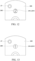
- Figs. 10 to 13 are plan views each showing a part of the speed control device 201.
- Fig. 14 is a plan view showing a part of a shift cam 226.
- the same elements as those of the speed control device 1 according to the first embodiment are denoted by the same reference numerals, and detailed description thereof will be omitted.
- the outer diameter D201 of the shift cam 226 is larger than the outer diameter D202 of the adjustment gears 27.
- a plurality of position indicators 241 are formed in the surface of the shift cam 226 of the centrifugal brake unit 213.
- the position indicators 241 indicate the rotational position of the shift cam 226.
- the position indicators 241 are located at different positions along the rotational direction of the shift cam 226.
- the position indicators 241 represent, for example, numbers.
- the position indicators 241 include position indicators 241a to 241d. In this embodiment, the position indicators 241a to 241d represent different numbers: "4", "3", "2", and "1".
- the cover plate 228 has one window 240 formed therein.
- Fig. 10 shows that the contact member 25 engages with the first engagement step 34a shown in Fig. 9 .
- the window 240 is positioned to overlap the position indicator 241a. Therefore, the position indicator 241a is visible through the window 240.
- Fig. 11 shows that the adjustment gear 27 is operated to rotate the shift cam 226, such that the contact member 25 engages with the second engagement step 34b shown in Fig. 9 . In this state, the position indicator 241b is visible through the window 240.
- Fig. 12 shows that the adjustment gear 27 is operated to rotate the shift cam 226, such that the contact member 25 engages with the third engagement step 34c shown in Fig. 9 .
- the position indicator 241c is visible through the window 240.
- Fig. 13 shows that the adjustment gear 27 is operated to rotate the shift cam 226, such that the contact member 25 engages with the fourth engagement step 34d shown in Fig. 9 .
- the position indicator 241d is visible through the window 240.
- the visible position indicator 241 changes depending on the rotational position of the shift cam 226.
- the window 240 can indicate the rotational position of the shift cam 226.
- each of the portions of the outer edge of the shift cam 226 that are located between the adjacent ones of the engagement steps 34 has a first portion 242 and a second portion 243.
- the first portion 242 and the second portion 243 have, for example, a straight shape.
- the first portion 242 and the second portion 243 formed between the nth and the (n+1)th engagement steps 34 (n is an integer equal to or greater than one)
- the first portion 242 is continuous to the nth engagement step 34.
- the second portion 243 is continuous to the (n+1)th engagement step 34. Therefore, the second portion 243 is closer to the (n+1)th engagement step 34 than is the first portion 242.
- the second portion 243 has a larger inclination angle with respect to the radial direction of the shift cam 226 than the first portion 242.
- the outer diameter D201 of the shift cam 226 is larger than the outer diameter D202 of the adjustment gears 27, as shown in Fig. 9 . Therefore, as with the speed control device 1 according to the first embodiment, the adjustment range of the braking force can be larger. This allows for a greater degree of freedom in setting the braking force. Thus, for example, the braking force can be set such that it is applied during traveling at a high speed.
- the cover plate 228 has the window 240 indicating the rotational position of the shift cam 226, making it easy to grasp the braking force of the centrifugal brake. Therefore, works such as setting of the rotation speed of the vehicle wheel 103 on which the centrifugal brake is activated can be easily performed.
- the window 240 can display the position indicators 241, making it easy to grasp the braking force of the centrifugal brake.
- the speed control device 201 can have a reduced number of window 240, which is advantageous in downsizing the device.
- a first portion 242 and a second portion 243 are formed between the nth engagement step 34 (n is an integer equal to or greater than one) and the (n+1)th engagement step 34, and the second portion 243 has a larger inclination angle. Therefore, when the contact member 25 shifts from the nth engagement step 34 to the (n+1)th engagement step 34, the radial movement distance can be secured in the first portion 242 where the load from the spring 24 is small. Therefore, in the second portion 243, where the load from the spring 24 is larger, the contact member 25 can be shifted to the (n+1)th engagement step 34 with a relatively low force. Therefore, the contact member 25 can be easily shifted from the nth engagement step 34 to the (n+1)th engagement step 34.
- the elastic member was a spring 24 (coil spring), but the elastic member may be composed of any element that can bias the brake shoe outward.
- the shape of the windows is not limited particularly.
- the windows may be shaped like a polygon such as a rectangle, or an ellipse.
- One or more (any plural number of) brake shoes may be provided.
- the planetary gear mechanism 80 has a two-stage configuration with a first-stage gear mechanism 110 and a second-stage gear mechanism 120, but this configuration is not limitative. A single-stage configuration is also acceptable.
- the above embodiments of the speed control devices 1 and 201 were described, by way of an example, to include the first wheel plate 60 and the second wheel plate 70 assembled together to constitute the wheel 50. Furthermore, the above embodiments of the speed control devices 1 and 201 were described, by way of an example, to be located in the inner housing space R constituted by the first housing space R1 of the first wheel plate 60 and the second housing space of the second wheel plate 70.
- the vehicle wheel 103 may be constituted by a single wheel and the speed control device assembled together.
- An example of this case is described below as a variation.
- the vehicle wheel 103 includes a wheel structure 17, which corresponds to the single wheel, and a tire 18.
- Fig. 15 does not show the axle 21.
- the wheel structure 17 includes a rim 251 and a disc 252.
- the rim 251 has a cylindrical shape.
- the tire 18 is attached to the rim 251.
- the disc 252 includes a mounting portion 253 and a plurality of spokes 254.
- Fig. 16 is a six-sided view of the vehicle wheel 103.
- Part (A) of Fig. 16 is a front view of the vehicle wheel 103.
- Part (B) of Fig. 16 is a left side view of the vehicle wheel 103.
- Part (C) of Fig. 16 is a right side view of the vehicle wheel 103.
- Part (D) of Fig. 16 is a top view of the vehicle wheel 103.
- Part (E) of Fig. 16 is a bottom view of the vehicle wheel 103.
- Part (F) of Fig. 16 is a rear view of the vehicle wheel 103.
- Fig. 17 is a perspective view of the vehicle wheel 103.
- the mounting portion 253 is mounted, for example, to a hub (not shown).
- the mounting portion 253 is located in the middle of the vehicle wheel 103, as viewed from the direction parallel to the rotation axis 20.
- the plurality of spokes 254 radiate from the mounting portion 253 to the rim 251.
- the spokes 254 connect between the mounting portion 253 and the rim 251.
- the number of spokes 254 provided is, for example, three or larger. As viewed from the direction parallel to the rotation axis 20, the width of each spoke 254 is gradually smaller toward the radially outward direction.
- the speed control device 250 in this case includes a brake drum 11, a housing 12, a centrifugal brake unit 13, a planetary gear mechanism 14, and a cap 15.
- the planetary gear mechanism 14 has a single-stage configuration.
- the brake drum 11 includes a tube 11A having a cylindrical shape.
- the brake drum 11 is fixed to the end of the axle (not shown).
- the housing 12 has a cylindrical shape.
- the housing 12 is attached to one end of brake drum 11.
- the cap 15 is removably attached to the outer surface of the wheel structure 17.
- the centrifugal brake unit 13 is provided inside the tube 11A of the brake drum 11.
- the centrifugal brake unit 13 is a mechanism for generating a braking force of the centrifugal brake between the centrifugal brake unit 13 and the brake drum 11.
- the centrifugal brake unit 13 is rotatable around the rotation axis 20.
- the wheel structure 17 is rotatable relative to the rotation axis 20. Thus, when the wheel structure 17 rotates, the rotational force is transmitted to the centrifugal brake unit 13 via the planetary gear mechanism 14.
- the wheel structure 17 has an opening 19 through which the window 40 of the cover plate 28 is visible.
- the vehicle wheel 103 and the speed control device 250 configured in this manner can also produce the same effects as in the above embodiments.
Landscapes
- Engineering & Computer Science (AREA)
- Mechanical Engineering (AREA)
- Chemical & Material Sciences (AREA)
- Combustion & Propulsion (AREA)
- Transportation (AREA)
- General Engineering & Computer Science (AREA)
- Health & Medical Sciences (AREA)
- Public Health (AREA)
- Braking Arrangements (AREA)
Abstract
A speed control device (1, 201, 250) according to the invention includes: a brake drum (11); a brake shoe (23) for reducing the rotation speed of the vehicle wheel (103) by a braking force produced by contact with an inner circumference of the brake drum (11); an elastic member (24) configured to bias the brake shoe (23); a contact member (25); a shift cam (26, 226) configured to increase or reduce a force of the contact member (25) pressing the elastic member (24); and an adjustment gear (27) for setting the rotational position of the shift cam (26, 226) to adjust the force pressing the elastic member (24). The outer diameter (D1, D201) of the shift cam (26, 226) is larger than the outer diameter (D2, D202) of the adjustment gear (27).
Description
- The present invention relates to a speed control device and a vehicle.
- For example, a vehicle such as a rollator used to assist a user in walking may be equipped with a speed control device for controlling the rotation speed of a vehicle wheel (see, for example, Patent Literature 1).
- The speed control device is installed on a vehicle wheel. The speed control device includes, for example, a brake drum, a brake shoe, an elastic member, a contact member, a cam, and an adjustment gear. The brake shoe contacts the inner circumferential surface of the brake drum. The elastic member biases the brake shoe. The cam applies a force in the compressive direction to the elastic member via the contact member. The adjustment gear sets the position of the cam in the rotational direction to adjust the force with which the contact member presses the elastic member.
- Patent Literature 1:
Japanese Patent Application Publication No. 2022-59838 - A larger adjustment range of braking force is being considered for the speed control device. If the adjustment range of the braking force can be larger, it is possible, for example, to apply the braking force during high speed traveling. However, in the structure of conventional speed control devices, it was difficult to enlarge the adjustment range of braking force.
- One aspect of the present invention provides a speed control device and a vehicle capable of enlarging the adjustment range of braking force.
- A speed control device according to one aspect of the invention is a speed control device provided on a vehicle wheel rotating around a rotation axis so as to control rotation speed of the vehicle wheel, the speed control device comprising: a brake drum; a brake shoe for reducing the rotation speed of the vehicle wheel by a braking force produced by contact with an inner circumference of the brake drum; an elastic member having one end and another end, the elastic member being configured to bias the brake shoe via the one end; a contact member provided on the other end of the elastic member; a shift cam provided so as to be rotatable around the rotation axis and configured to increase or reduce a force of the contact member pressing the elastic member in accordance with a rotational position of the shift cam; and an adjustment gear operated by an external input to rotate the shift cam, so as to set the rotational position of the shift cam to adjust the force pressing the elastic member. The shift cam has a larger diameter than the adjustment gear.
- In the speed control device, the outer diameter of the shift cam is larger than the outer diameter of the adjustment gear, allowing for a larger adjustment range of the braking force. This also allows for a greater degree of freedom in setting the braking force. Thus, for example, the braking force can be set such that it is applied during traveling at a higher speed than it was before.
- The speed control device may further comprise a cover plate covering at least the shift cam. The cover plate may have at least one window formed therein for indicating the rotational position of the shift cam. In this case, the window can indicate the braking force of the centrifugal brake so that it can be grasped easily. Therefore, works such as setting of the rotation speed of the vehicle wheel on which the centrifugal brake is activated can be easily performed.
- In the speed control device, the at least one window may comprise a plurality of windows. The plurality of windows may be located at different positions along a rotational direction of the shift cam, and a number of windows overlapping the shift cam may change in accordance with the rotational position of the shift cam. In this case, it is possible to indicate the braking force of the centrifugal brake so that it can be grasped more easily.
- In the speed control device, the shift cam may have a position indicator for indicating the rotational position of the shift cam. The at least one window may be formed such that the position indicator is visible. In this case, it is possible to indicate the braking force of the centrifugal brake so that it can be grasped more easily.
- A vehicle according to one aspect of the invention comprises: the speed control device described above; and a vehicle wheel having the speed control device provided thereon. Since the vehicle is equipped with the speed control device, the adjustment range of the braking force can be larger. This allows for a greater degree of freedom in setting the braking force.
- One aspect of the present invention makes is possible to enlarge the adjustment range of braking force.
-
-
Fig. 1 is a schematic diagram of a rollator, or a vehicle according to an embodiment. -
Fig. 2 is an exploded perspective view of a speed control device and a vehicle wheel according to a first embodiment. -
Fig. 3 is a plan view of a centrifugal brake unit shown inFig. 2 . -
Fig. 4 is a plan view of the cover plate shown inFig. 2 . -
Fig. 5 is a plan view of a part of a speed control device according to the first embodiment. -
Fig. 6 is a plan view of a part of the speed control device according to the first embodiment. -
Fig. 7 is a plan view of a part of the speed control device according to the first embodiment. -
Fig. 8 is a plan view of a part of the speed control device according to the first embodiment. -
Fig. 9 is a plan view of a part of a speed control device according to a second embodiment. -
Fig. 10 is a plan view of a part of the speed control device according to the second embodiment. -
Fig. 11 is a plan view of a part of the speed control device according to the second embodiment. -
Fig. 12 is a plan view of a part of the speed control device according to the second embodiment. -
Fig. 13 is a plan view of a part of the speed control device according to the second embodiment. -
Fig. 14 is a plan view showing a part of a shift cam of the speed control device according to the second embodiment. -
Fig. 15 is an exploded perspective view showing a variation of the speed control device and the vehicle wheel according to the embodiment. -
Fig. 16 is a six-sided view of the vehicle wheel shown inFig. 15 . -
Fig. 17 is a perspective view of the vehicle wheel shown inFig. 15 . - A speed control device according to the embodiments of the present invention will be hereinafter described in detail with reference to the drawings.
-
Fig. 1 is a schematic diagram of arollator 101, or a vehicle according to an embodiment. Therollator 101 is used, for example, to assist a user in walking. For this embodiment, the vertical direction is defined as it is when therollator 101 is used. The front direction is defined as the traveling direction of therollator 101 being used, and the rear direction is defined as the opposite to the traveling direction. Further, the vehicle width direction of therollator 101 is defined as the direction orthogonal to the vertical direction and the front-rear direction. - The
rollator 101 includes abody 102, a plurality ofvehicle wheels 103, and ahandling portion 104. Thebody 102 includes alower frame 105 and a plurality ofvertical frames 106. Thelower frame 105 includes afront frame 107 and two side frames 108. The side frames 108 extend rearward from the ends of thefront frame 107. The plurality ofvertical frames 106 extend upward from the front and rear of the side frames 108. Thevehicle wheels 103 are located at the front and rear of the side frames 108. The handlingportion 104 is U-shaped. The handlingportion 104 is connected to the upper ends of thevertical frames 106. - The
rollator 101 travels as the user pushes the handlingportion 104 with his or her hand. For this embodiment, therollator 101 is an example of the vehicle. However, the vehicle is not limited to a rollator, but can also be, for example, a cart for transporting luggage or a buggy for carrying an infant. -
Fig. 2 is an exploded perspective view of aspeed control device 1 and avehicle wheel 103 according to a first embodiment.Fig. 3 is a plan view showing acentrifugal brake unit 13 included in thespeed control device 1.Fig. 4 is a plan view showing acover plate 28 included in thespeed control device 1.Figs. 5 to 8 are plan views each showing a part of thespeed control device 1. - As shown in
Fig. 1 , thevehicle wheels 103 are mounted onbrackets 109 provided at the lower portions of the front and rear of the side frames 108. Thevehicle wheels 103 are thus secured to thebody 102 via thebrackets 109. The plurality ofvehicle wheels 103 provided on thebody 102 are configured in the same manner. Therefore, only one of thevehicle wheels 103 will be hereinafter described, and theother vehicle wheels 103 will not be described. - As shown in
Figs. 1 and2 , thevehicle wheel 103 includes anaxle 21 supported by thebracket 109, a disc-shapedwheel 50 rotatably supported by theaxle 21, and atire 51 mounted on the outer circumference of thewheel 50. Theaxle 21 protrudes from thebracket 109 toward the outside in the vehicle width direction. Theaxle 21 is positioned so that the axial direction of theaxle 21 coincides with the vehicle width direction. The central axis that extends through the center of theaxle 21 in the vehicle width direction is therotation axis 20. Thus, thevehicle wheel 103 rotates around therotation axis 20. In a view along therotation axis 20, the directions intersecting therotation axis 20 are defined as the radial directions, and the direction circling around therotation axis 20 is defined as the circumferential direction. - The
wheel 50 includes afirst wheel plate 60 and asecond wheel plate 70 that overlap in the axial direction of theaxle 21. Thefirst wheel plate 60 and thesecond wheel plate 70 have a disc-like outer shape and are rotatably supported by theaxle 21. - The
first wheel plate 60 is located closer to thebracket 109 than is thesecond wheel plate 70. Thefirst wheel plate 60 includes afirst housing portion 61 having a bottomed cylindrical shape and opening toward thesecond wheel plate 70, afirst rim 62 having a cylindrical shape and positioned to surround thefirst housing portion 61 externally in the radial direction, and a plurality offirst spokes 63 connecting thefirst housing portion 61 and thefirst rim 62 in the radial direction. - The
first housing portion 61 includes a firstbottom wall 61a having a disc-like shape and a firstcircumferential wall 61b that protrudes from the outer edge of the firstbottom wall 61a toward thesecond wheel plate 70 and extends all along the outer edge of the firstbottom wall 61a. The inner space of thefirst housing portion 61 serves as a first housing space R1, which is open toward thesecond wheel plate 70. The firstbottom wall 61a includes a bearinghousing 64 that houses a bearing (not shown). The bearinghousing 64 is positioned coaxially with therotation axis 20 and formed cylindrically to protrude inward in the vehicle width direction. Thefirst wheel plate 60 is thus rotatably supported by theaxle 21 via the bearing housed in the bearinghousing 64. - In addition, the first
bottom wall 61a has a plurality of first planetary support pins 65 integrally formed thereon. In the example shown, three first planetary support pins 65 are formed at regular intervals in the circumferential direction around therotation axis 20. The first planetary support pins 65 are formed to protrude from the firstbottom wall 61a toward thesecond wheel plate 70. The first planetary support pins 65 constitute a part of thespeed control device 1. - Three
first spokes 63 are formed at regular intervals in the circumferential direction around therotation axis 20. Thefirst spokes 63 are formed to extend radially outward from the outer circumference of the firstcircumferential wall 61b and is connected to the inner circumference of thefirst rim 62. Thefirst spokes 63 are formed so that their circumferential width along the circumferential direction is gradually smaller toward the radially outward direction. The number and shape of thefirst spokes 63 are not limited to these, but may be changed as needed. Thefirst spokes 63 each have abolt insertion hole 63a that extends through thefirst spokes 63 in the vehicle width direction. - The
second wheel plate 70 includes asecond housing portion 71 having a bottomed cylindrical shape and opening toward thefirst wheel plate 60, asecond rim 72 having a cylindrical shape and positioned to surround thesecond housing portion 71 externally in the radial direction, and a plurality ofsecond spokes 73 connecting thesecond housing portion 71 and thesecond rim 72 in the radial direction. - The
second housing portion 71 includes a secondbottom wall 71a having a disc-like shape and a secondcircumferential wall 71b that protrudes from the outer edge of the secondbottom wall 71a toward thefirst wheel plate 60 and extends all along the outer edge of the secondbottom wall 71a. The inner space of thesecond housing portion 71 serves as a second housing space (not shown), which is open toward thefirst wheel plate 60. - In addition, the second
bottom wall 71a has anopening 19 that extends through the secondbottom wall 71a in the vehicle width direction. Theopening 19 serves as a viewing window for externally viewing awindow 40 of thecover plate 28, which will be described later. In addition, the secondbottom wall 71a has acover mounting portion 75 integrally formed thereon. Thecover mounting portion 75 has a cylindrical shape and protrudes outward in the vehicle width direction. Thus, theopening 19 is positioned inside thecover mounting portion 75. - The
second housing portion 71, configured as described above, is formed in a bottomed cylindrical shape having the same outer diameter as thefirst housing portion 61. Thesecond housing portion 71 is opposed to thefirst housing portion 61 from the outside in the vehicle width direction. - Three
second spokes 73 are formed at regular intervals in the circumferential direction around therotation axis 20. Thesecond spokes 73 are formed to extend radially outward from the outer circumference of the secondcircumferential wall 71b and is connected to the inner circumference of thesecond rim 72. Thesecond spokes 73 are formed so that their circumferential width along the circumferential direction is gradually smaller toward the radially outward direction. In particular, thesecond spokes 73 are formed in the same number, shape, size, etc. as thefirst spokes 63, and are opposed to thefirst spokes 63 from the outside in the vehicle width direction. - The
second spokes 73 each have a bolt hole (threaded hole) (not shown) that is open toward the inside in the vehicle width direction. The bolt holes are opposed in the vehicle width direction to thebolt insertion holes 63a formed in thefirst spokes 63. - The
first wheel plate 60 and thesecond wheel plate 70, configured as described above, coaxially overlap with each other and are fastened together by bolts (not shown). Thus, thefirst wheel plate 60 and thesecond wheel plate 70 are integrated together to constitute thewheel 50. The bolts are screwed into the bolt holes from the inside in the vehicle width direction through thebolt insertion holes 63a. In addition, thefirst wheel plate 60 and thesecond wheel plate 70 are assembled together so that the opening of the first housing space R1 and the opening of the second housing space overlap with each other. With this arrangement, an inner housing space R is formed inside thewheel 50 by the first housing space R1 and the second housing space. In addition, thefirst wheel plate 60 and thesecond wheel plate 70 are assembled together so that thefirst spokes 63 and thesecond spokes 73 are assembled together to serve asspokes 55. - The
tire 51 is integrally formed to surround thewheel 50 externally in the radial direction, thewheel 50 being constituted by thefirst wheel plate 60 and thesecond wheel plate 70 assembled together. Specifically, thetire 51 is assembled to thewheel 50 with its inner circumference in contact with the outer circumference of the wheel 50 (the outer circumference of thefirst rim 62 in thefirst wheel plate 60 and the outer circumference of thesecond rim 72 in the second wheel plate 70) from the outside in the radial direction. - The
speed control device 1 is positioned in the inner housing space R of thewheel 50 described above. Thespeed control device 1 includes aplanetary gear mechanism 80, aninternal gear 90, abrake drum 11, acentrifugal brake unit 13, and acap 15. - The
planetary gear mechanism 80 has a two-stage configuration and is mainly located in the first housing space R1 of thefirst wheel plate 60. Theplanetary gear mechanism 80 includes a first-stage gear mechanism 110 and a second-stage gear mechanism 120. The first-stage gear mechanism 110 is located on the firstbottom wall 61a of thefirst housing portion 61, and the second-stage gear mechanism 120 is located on the outer side of the first-stage gear mechanism 110 in the vehicle width direction. - The first-
stage gear mechanism 110 includes a first sun gear (not shown) rotatably supported on theaxle 21, and a plurality of firstplanetary gears 111 arranged around the first sun gear. The first sun gear is formed integrally with a secondplanetary carrier 122, which will be described later. Three firstplanetary gears 111 are arranged at regular intervals in the circumferential direction around therotation axis 20 and are each meshed with the first sun gear. In addition, the firstplanetary gears 111 are rotatably supported by the first planetary support pins 65 integrally formed on the firstbottom wall 61a of thefirst housing portion 61. Thus, the firstbottom wall 61a serves as a planetary carrier that rotatably supports the plurality of firstplanetary gears 111. - The second-
stage gear mechanism 120 includes a second sun gear (not shown) rotatably supported on theaxle 21, a plurality of secondplanetary gears 121 arranged around the second sun gear, and a secondplanetary carrier 122 that rotatably supports the plurality of secondplanetary gears 121. The second sun gear is formed integrally with a support plate 29 (described later) included in thecentrifugal brake unit 13, and is positioned in line with the first sun gear in the vehicle width direction. - The second
planetary carrier 122 includes a disc-shapedcarrier plate 123 and second planetary support pins 124 protruding from thecarrier plate 123 toward the outside in the vehicle width direction. Thecarrier plate 123 has the first sun gear formed thereon, protruding toward the inside in the vehicle width direction. Three second planetary support pins 124 are formed at regular intervals in the circumferential direction around therotation axis 20, so as to correspond to the first planetary support pins 65. The second planetary support pins 124 constitute a part of thespeed control device 2. Three secondplanetary gears 121 are arranged at regular intervals in the circumferential direction around therotation axis 20 and are each meshed with the second sun gear. In addition, the secondplanetary gears 121 are rotatably supported by the second planetary support pins 124 formed on the secondplanetary carrier 122. - The
internal gear 90 is formed in a cylindrical shape surrounding the firstplanetary gears 111 of the first-stage gear mechanism 110 and the secondplanetary gears 121 of the second-stage gear mechanism 120. Theinternal gear 90 has internal teeth continuously formed on the entire inner circumference. The internal gear meshes with the firstplanetary gears 111 and the secondplanetary gears 121. - The
brake drum 11 is positioned on the outer side of theinternal gear 90 in the vehicle width direction. Thebrake drum 11 is formed in a bottomed cylindrical shape including acylindrical portion 11a and abottom portion 11b, with the opening facing inward (toward the internal gear 90) in the vehicle width direction. Thecylindrical portion 11a of thebrake drum 11 surrounds theinternal gear 90 externally in the radial direction. The inner circumference of thecylindrical portion 11a is fitted on the outer circumference of theinternal gear 90. Thus, theinternal gear 90 and thebrake drum 11 are assembled together. - A through hole (not shown) is formed in the middle of the
bottom portion 11b, to extend through thebottom portion 11b in the vehicle width direction. The through hole is coaxial with therotation axis 20. In addition, the through hole receives a bush provided on theaxle 21 for example, and press-fitted in the through hole. Thus, thebrake drum 11 is integrally fixed to theaxle 21. Therefore, theinternal gear 90 is integrally fixed to theaxle 21 via thebrake drum 11. In addition, thebottom portion 11b has a plurality ofoperation windows 11c that extend through thebottom portion 11b in the vehicle width direction. This arrangement allows communication between the outside of thevehicle wheel 103 and the inside of thebrake drum 11 through theoperation windows 11c and theopening 19 formed in thesecond wheel plate 70. - The
cap 15 is removably attached to thecover mounting portion 75 of thesecond wheel plate 70. Thus, thecap 15 normally covers theopening 19. - The
centrifugal brake unit 13 is positioned on the inner side of thebrake drum 11, while being positioned on the outer side of theplanetary gear mechanism 80 in the vehicle width direction. Specifically, thecentrifugal brake unit 13 is positioned between the second-stage gear mechanism 120 and thebottom portion 11b of thebrake drum 11, and is located inside thecylindrical portion 11a of thebrake drum 11. Thecentrifugal brake unit 13 is a mechanism for generating a braking force of the centrifugal brake between thecentrifugal brake unit 13 and thebrake drum 11. Thecentrifugal brake unit 13 is rotatable around therotation axis 20. - As shown in
Figs. 3 and4 , thecentrifugal brake unit 13 includes twobrake shoes 23, two springs 24 (elastic members), twocontact members 25, ashift cam 26, two adjustment gears 27, acover plate 28, and asupport plate 29.Fig. 3 does not show theaxle 21. - As shown in
Fig. 3 , each of thebrake shoes 23 is shaped like a long plate extending along the circumferential direction around therotation axis 20. Thebrake shoe 23 is rotatably supported by thesupport plate 29 via a rotatingshaft 31. The rotatingshaft 31 is located at a position off the longitudinally middle portion of thebrake shoe 23 toward one end of thebrake shoe 23. The one end of thebrake shoe 23 is biased by thespring 24 outward in the radial direction of thesupport plate 29. The twobrake shoes 23 are positioned opposite to each other in the radial direction of thesupport plate 29, with the center of the support plate 29 (rotation axis 20) interposed therebetween. - The
brake shoes 23 shown inFig. 2 and thebrake shoes 23 shown inFig. 3 use differentrotating shafts 31 but have the same basic configuration and operation, with only the difference in rotational direction. - Each of the
brake shoes 23 has an outer peripheral surface that is curved along its longitudinal direction. Apad 30 is attached to the outer peripheral surface of the other end of thebrake shoe 23. Thepad 30 is provided on the opposite side to the one end at which thebrake shoe 23 is biased by thespring 24, with the rotatingshaft 31 positioned between thepad 30 and the one end. When the rotation speed of thevehicle wheel 103 is high, thebrake shoe 23 rotates around the rotatingshaft 31 to bring thepad 30 into contact with the inner circumference of thecylindrical portion 11a of thebrake drum 11. Thebrake shoe 23 reduces the rotation speed of thevehicle wheel 103 by the braking force produced by contact with the inner circumference of thebrake drum 11. - The
spring 24 is, for example, a coil spring, having one end and the other end. Thespring 24 is provided between the one end of thebrake shoe 23 and thecontact member 25. Thespring 24 extends along the radial direction of thesupport plate 29. The one end of thespring 24 is in contact with the one end of thebrake shoe 23 and biases the one end of thebrake shoe 23 outward in the radial direction of thesupport plate 29. The two springs 24 are positioned opposite to each other in the radial direction of thesupport plate 29, with the center of the support plate 29 (rotation axis 20) interposed therebetween. - When the rotation speed of the
vehicle wheel 103 is below a predetermined value, thespring 24 restricts the contact between thebrake drum 11 and thebrake shoe 23, resulting in a smaller braking force. When the rotation speed of thevehicle wheel 103 exceeds the predetermined value mentioned above, thespring 24 allows contact between thebrake drum 11 and thebrake shoe 23, resulting in a larger braking force. Thespring 24 is covered by aprotective cover 22 attached to thesupport plate 29. Thus, thespring 24 is protected by theprotective cover 22, which prevents dust and other particles from adhering to thespring 24.Fig. 2 shows theprotective cover 22 covering thespring 24. - Each of the
contact members 25 is provided at the other end of the spring 24 (the part opposite to the one end). The twocontact members 25 are positioned opposite to each other in the radial direction of thesupport plate 29, with the center of the support plate 29 (rotation axis 20) interposed therebetween. Thecontact members 25 are movable along the direction of expansion and contraction of thespring 24. - The
shift cam 26 is mounted to thesupport plate 29 so as to be rotatable around therotation axis 20. Theshift cam 26 is in direct or indirect contact with thecontact members 25. Theshift cam 26 increases or reduces the force with which thecontact members 25 press thesprings 24. - The
shift cam 26 has two meshingportions 32 at two locations on its outer edge. The meshingportions 32 have a plurality ofteeth 32a. The two meshingportions 32 are positioned opposite to each other in the radial direction of thesupport plate 29, with the center of the shift cam 26 (rotation axis 20) interposed therebetween. - The
shift cam 26 has two cam portions 33 (drive portions) at two locations on its outer edge other than the meshingportions 32. Each of thecam portions 33 has a plurality of engagement steps 34 at different distances from therotation axis 20. The plurality of engagement steps 34 include afirst engagement step 34a, asecond engagement step 34b, athird engagement step 34c, and afourth engagement step 34d. For this embodiment, thefirst engagement step 34a, thesecond engagement step 34b, thethird engagement step 34c, and thefourth engagement step 34d are collectively referred to as "the engagement steps 34a to 34d". - The
second engagement step 34b is formed at a larger distance from therotation axis 20 than thefirst engagement step 34a. Thethird engagement step 34c is formed at a larger distance from therotation axis 20 than thesecond engagement step 34b. Thefourth engagement step 34d is formed at a larger distance from therotation axis 20 than thethird engagement step 34c. The engagement steps 34a to 34d can engage with thecontact member 25. - When the
contact member 25 engages with thefirst engagement step 34a (seeFig. 3 ), the force of thespring 24 pressing thebrake shoe 23 is smallest. Therefore, thebrake shoe 23 is allowed to rotate with a relatively small centrifugal force. Therefore, when the rotation speed of thevehicle wheel 103 is relatively low, thebrake shoe 23 contacts the inner circumference of thebrake drum 11 to exert a braking force. - When the
contact member 25 engages with thesecond engagement step 34b, the force of thespring 24 pressing thebrake shoe 23 is slightly larger than when thecontact member 25 engages with thefirst engagement step 34a. Therefore, thebrake shoe 23 is allowed to rotate when subjected to a large centrifugal force. Therefore, when the rotation speed of thevehicle wheel 103 is relatively high, thebrake shoe 23 contacts the inner circumference of thebrake drum 11 to exert a braking force. - When the
contact member 25 engages with thethird engagement step 34c, the force of thespring 24 pressing thebrake shoe 23 is still larger. Therefore, the braking force is exerted when the rotation speed of thevehicle wheel 103 is higher than when thecontact member 25 engages with thesecond engagement step 34b. When thecontact member 25 engages with thefourth engagement step 34d, the force of thespring 24 pressing thebrake shoe 23 is yet larger. Therefore, the braking force is exerted when the rotation speed of thevehicle wheel 103 is higher than when thecontact member 25 engages with thethird engagement step 34c. - The engagement steps 34a to 34d are provided along the circumferential direction around the center of the shift cam 26 (rotation axis 20) and are arranged in the circumferential direction in this order. Therefore, the
cam portion 33 allows selection from the engagement steps 34a to 34d in accordance with the rotational position of theshift cam 26, thereby increasing or reducing the force pressing thespring 24. The twocam portions 33 are positioned opposite to each other in the radial direction of thesupport plate 29, with the center of the shift cam 26 (rotation axis 20) interposed therebetween. - Each of the adjustment gears 27 has a plurality of
teeth 27a that mesh with the meshingportion 32 of theshift cam 26. Theadjustment gear 27 is rotatably supported by thesupport plate 29. Theadjustment gear 27 has an engagement hole that can be engaged with a rotating tool such as a hexagonal wrench. Theadjustment gear 27 is capable of transmitting to thecam portion 33 the force input from the outside via the rotating tool engaged in the engagement hole. - Thus, the
adjustment gear 27 can rotate theshift cam 26 relative to thesupport plate 29. Theadjustment gear 27 is operated (rotated) by an external input to rotate theshift cam 26, thereby setting the rotational position of theshift cam 26 to adjust the force with which thecontact member 25 presses thespring 24. The two adjustment gears 27 are positioned opposite to each other in the radial direction of thesupport plate 29, with the center of the support plate 29 (rotation axis 20) interposed therebetween. - The
shift cam 26 has an outer diameter (shift cam diameter) D1 as the maximum outer diameter. The outer diameter D1 is the outer diameter at the meshingportions 32. The adjustment gears 27 have an outer diameter (adjustment gear diameter) D2 as the maximum outer diameter. The outer diameter D1 of theshift cam 26 is larger than the outer diameter D2 of the adjustment gears 27. Therefore, the formula D1 > D2 holds. The ratio of D1 to D2 (D1/D2) is preferably 3 or larger. If the ratio of D1 to D2 (D1/D2) falls within this range, the adjustment range of the braking force can be larger. The ratio of D1 to D2 (D1/D2) may be, for example, 10 or smaller. If the ratio of D1 to D2 (D1/D2) falls within this range, the size of theshift cam 26 can be reduced. Thus, the size of thespeed control device 1 can be reduced. - As shown in
Figs. 2 and4 , thecover plate 28 is shaped like a disc and is positioned on the outer side of thesupport plate 29 in the vehicle width direction. As shown inFigs. 2 and5 , thecover plate 28 covers the entirecentrifugal brake unit 13 and is integrally assembled to thesupport plate 29.Fig. 5 shows only a part of thecover plate 28 in a simplified manner. The same applies toFigs. 6 to 8 . Thecover plate 28 has a different color than theshift cam 26. For example, the color of thecover plate 28 has a different brightness than that of theshift cam 26. For example, the color of thecover plate 28 is darker than that of theshift cam 26. - As shown in
Figs. 4 and5 , thecover plate 28 has a plurality ofwindows 40. Thewindows 40 extend through thecover plate 28 in the thickness direction. The plurality ofwindows 40 include afirst window 40a, asecond window 40b, athird window 40c, and afourth window 40d. For this embodiment, thefirst window 40a, thesecond window 40b, thethird window 40c, and thefourth window 40d are collectively referred to as "thewindows 40a to 40d". - The
windows 40a to 40d are arranged along the circumferential direction of thesupport plate 29. Thus, thewindows 40a to 40d are located at different positions along the rotational direction of theshift cam 26. In addition, thewindows 40a to 40d are arranged in this order along the circumferential direction of thesupport plate 29 and spaced apart in the circumferential direction of thesupport plate 29. When thecap 15 is removed, thewindows 40a to 40d are visible from the outside through theopening 19 in thesecond wheel plate 70 and theoperation windows 11c in the brake drum 11 (seeFig. 2 ). - The
windows 40a to 40d have a circular shape, for example. The sizes (e.g., inner diameters) of thewindows 40a to 40d may be the same or different from each other. The sizes (e.g., inner diameters) of thewindows 40a to 40d may be larger or smaller in this order. -
Fig. 5 shows that thecontact member 25 engages with thefirst engagement step 34a. In this state, theshift cam 26 is positioned to overlap all of the fourwindows 40a to 40d. In other words, theshift cam 26 is positioned to encompass all of the fourwindows 40a to 40d in plan view. Therefore, theshift cam 26 is visible through the fourwindows 40a to 40d. Since thecover plate 28 has a different color than theshift cam 26, theshift cam 26 is easily visible through thewindow 40a. -
Fig. 6 shows that theadjustment gear 27 is operated to rotate theshift cam 26, such that thecontact member 25 engages with thesecond engagement step 34b. In this state, theshift cam 26 is positioned to overlap three of the fourwindows 40a to 40d, namely, thewindows 40b to 40d. Therefore, theshift cam 26 is visible through the threewindows 40b to 40d. -
Fig. 7 shows that theadjustment gear 27 is operated to rotate theshift cam 26, such that thecontact member 25 engages with thethird engagement step 34c. In this state, theshift cam 26 is positioned to overlap two of the fourwindows 40a to 40d, namely, thewindows shift cam 26 is visible through the twowindows -
Fig. 8 shows that theadjustment gear 27 is operated to rotate theshift cam 26, such that thecontact member 25 engages with thefourth engagement step 34d. In this state, theshift cam 26 is positioned to overlap one of the fourwindows 40a to 40d, namely, thewindow 40d. Therefore, theshift cam 26 is visible through thewindow 40d. - As shown in
Figs. 5 to 8 , the number ofwindows 40 through which theshift cam 26 is visible changes depending on the rotational position of theshift cam 26. Thus, thewindows 40 can indicate the rotational position of theshift cam 26. - As shown in
Fig. 3 , thesupport plate 29 has a circular shape for example, and rotatably supports thebrake shoes 23. Further, thesupport plate 29 rotatably supports theshift cam 26 and the adjustment gears 27. Still further, thesupport plate 29 has a second sun gear (not shown) formed thereon, which protrudes inward in the vehicle width direction. As mentioned above, the plurality (three) of secondplanetary gears 121 included in the second-stage gear mechanism 120 mesh with the second sun gear. Thus, as shown inFig. 2 , the two-stageplanetary gear mechanism 80 is able to transmit the rotational force of thewheel 50 to thesupport plate 29. - A description is given of example operation of the
speed control device 1 configured as described above. As shown inFig. 1 , when the handlingportion 104 of therollator 101 is pushed by the user, thevehicle wheels 103 rotate and therollator 101 moves. As thevehicle wheels 103 rotate, the rotational force is transmitted to thesupport plate 29 of thecentrifugal brake unit 13. Thus, thesupport plate 29 rotates around therotation axis 20 of the axle 21 (seeFig. 3 ). - When the rotation speed of the
vehicle wheel 103 is below a predetermined value, the rotation speed of thesupport plate 29 is also low. Therefore, thebrake shoe 23 does not contact the inner circumference of thebrake drum 11, and the braking force of the centrifugal brake is kept low. On the other hand, when the rotation speed of thevehicle wheel 103 exceeds the predetermined value, thesupport plate 29 rotates at a high speed. Therefore, thebrake shoe 23 is rotated by the centrifugal force around the rotatingshaft 31 against the elastic force of thespring 24, elastically deforming thespring 24 so that thespring 24 is compressed. Thus, thepad 30 of thebrake shoe 23 can be pressed against the inner circumference of thebrake drum 11. As a result, the braking force of the centrifugal brake can be increased, and the speed of thevehicle wheel 103 can be reduced. - As shown in
Fig. 2 , in order to change the rotation speed of thevehicle wheel 103 on which the centrifugal brake is activated, thecap 15 is removed from thesecond wheel plate 70. Theadjustment gear 27 shown inFig. 3 is then rotated using a rotating tool such as a hexagonal wrench. Rotating theshift cam 26 with theadjustment gear 27 allows selection of theengagement step 34 engaged by thecontact member 25 from the engagement steps 34a to 34d (seeFigs. 5 to 8 ). Thus, the force with which thecontact member 25 presses thespring 24 can be adjusted, and the braking force of the centrifugal brake can be set. - In the
speed control device 1, the outer diameter D1 of theshift cam 26 is larger than the outer diameter D2 of the adjustment gears 27, as shown inFig. 3 . Since the outer diameter D1 of theshift cam 26 is larger, the outer edge of theshift cam 26 can be longer. This allows for larger differences between the distances from the rotatingaxis 20 to the plurality of engagement steps 34 (34a to 34d) of theshift cam 26, thus allowing for a larger adjustment range of the braking force. In addition, the number of engagement steps 34 can be increased, allowing for a greater degree of freedom in setting the braking force. Thus, for example, the braking force can be set such that it is applied during traveling at a higher speed than it was before. - In the
speed control device 1, thecover plate 28 has thewindows 40 indicating the rotational position of theshift cam 26, making it easy to grasp the braking force of the centrifugal brake. Therefore, works such as setting of the rotation speed of thevehicle wheel 103 on which the centrifugal brake is activated can be easily performed. - In the
speed control device 1, the number ofwindows 40 overlapping theshift cam 26 changes in accordance with the rotational position of theshift cam 26, thus making it easy to grasp the braking force of the centrifugal brake. - Since the
rollator 101 is equipped with thespeed control device 1, the adjustment range of the braking force can be larger. This allows for a greater degree of freedom in setting the braking force. Thus, for example, the braking force can be set such that it is applied during traveling at a higher speed than it was before. -
Fig. 9 is a plan view of a part of aspeed control device 201 according to a second embodiment.Figs. 10 to 13 are plan views each showing a part of thespeed control device 201.Fig. 14 is a plan view showing a part of ashift cam 226. For this embodiment, the same elements as those of thespeed control device 1 according to the first embodiment (seeFig. 3 ) are denoted by the same reference numerals, and detailed description thereof will be omitted. - As shown in
Fig. 9 , the outer diameter D201 of theshift cam 226 is larger than the outer diameter D202 of the adjustment gears 27. - In the
speed control device 201, a plurality ofposition indicators 241 are formed in the surface of theshift cam 226 of thecentrifugal brake unit 213. Theposition indicators 241 indicate the rotational position of theshift cam 226. Theposition indicators 241 are located at different positions along the rotational direction of theshift cam 226. Theposition indicators 241 represent, for example, numbers. Theposition indicators 241 includeposition indicators 241a to 241d. In this embodiment, theposition indicators 241a to 241d represent different numbers: "4", "3", "2", and "1". As shown inFig. 10 , thecover plate 228 has onewindow 240 formed therein. -
Fig. 10 shows that thecontact member 25 engages with thefirst engagement step 34a shown inFig. 9 . In this state, thewindow 240 is positioned to overlap theposition indicator 241a. Therefore, theposition indicator 241a is visible through thewindow 240.Fig. 11 shows that theadjustment gear 27 is operated to rotate theshift cam 226, such that thecontact member 25 engages with thesecond engagement step 34b shown inFig. 9 . In this state, theposition indicator 241b is visible through thewindow 240. -
Fig. 12 shows that theadjustment gear 27 is operated to rotate theshift cam 226, such that thecontact member 25 engages with thethird engagement step 34c shown inFig. 9 . In this state, theposition indicator 241c is visible through thewindow 240.Fig. 13 shows that theadjustment gear 27 is operated to rotate theshift cam 226, such that thecontact member 25 engages with thefourth engagement step 34d shown inFig. 9 . In this state, theposition indicator 241d is visible through thewindow 240. - As shown in
Figs. 10 to 13 , thevisible position indicator 241 changes depending on the rotational position of theshift cam 226. Thus, thewindow 240 can indicate the rotational position of theshift cam 226. - As shown in
Fig. 14 , each of the portions of the outer edge of theshift cam 226 that are located between the adjacent ones of the engagement steps 34 has afirst portion 242 and asecond portion 243. Thefirst portion 242 and thesecond portion 243 have, for example, a straight shape. As to thefirst portion 242 and thesecond portion 243 formed between the nth and the (n+1)th engagement steps 34 (n is an integer equal to or greater than one), thefirst portion 242 is continuous to thenth engagement step 34. Thesecond portion 243 is continuous to the (n+1)th engagement step 34. Therefore, thesecond portion 243 is closer to the (n+1)th engagement step 34 than is thefirst portion 242. Thesecond portion 243 has a larger inclination angle with respect to the radial direction of theshift cam 226 than thefirst portion 242. - In the
speed control device 201, the outer diameter D201 of theshift cam 226 is larger than the outer diameter D202 of the adjustment gears 27, as shown inFig. 9 . Therefore, as with thespeed control device 1 according to the first embodiment, the adjustment range of the braking force can be larger. This allows for a greater degree of freedom in setting the braking force. Thus, for example, the braking force can be set such that it is applied during traveling at a high speed. - In the
speed control device 201, thecover plate 228 has thewindow 240 indicating the rotational position of theshift cam 226, making it easy to grasp the braking force of the centrifugal brake. Therefore, works such as setting of the rotation speed of thevehicle wheel 103 on which the centrifugal brake is activated can be easily performed. - In the
speed control device 201, thewindow 240 can display theposition indicators 241, making it easy to grasp the braking force of the centrifugal brake. Thespeed control device 201 can have a reduced number ofwindow 240, which is advantageous in downsizing the device. - In the
speed control device 201, as shown inFig. 14 , afirst portion 242 and asecond portion 243 are formed between the nth engagement step 34 (n is an integer equal to or greater than one) and the (n+1)th engagement step 34, and thesecond portion 243 has a larger inclination angle. Therefore, when thecontact member 25 shifts from thenth engagement step 34 to the (n+1)th engagement step 34, the radial movement distance can be secured in thefirst portion 242 where the load from thespring 24 is small. Therefore, in thesecond portion 243, where the load from thespring 24 is larger, thecontact member 25 can be shifted to the (n+1)th engagement step 34 with a relatively low force. Therefore, thecontact member 25 can be easily shifted from thenth engagement step 34 to the (n+1)th engagement step 34. - In the above description of the embodiments of the invention, the features of the embodiments and the combinations thereof are mere examples. The embodiments can be modified by adding, omitting and replacing some or all of the features without departing from the scope of the invention. The present invention is not limited by the embodiments.
- For example, in the above embodiments of the
speed control devices speed control devices planetary gear mechanism 80 has a two-stage configuration with a first-stage gear mechanism 110 and a second-stage gear mechanism 120, but this configuration is not limitative. A single-stage configuration is also acceptable. - Further, the above embodiments of the
speed control devices first wheel plate 60 and thesecond wheel plate 70 assembled together to constitute thewheel 50. Furthermore, the above embodiments of thespeed control devices first wheel plate 60 and the second housing space of thesecond wheel plate 70. - However, these cases are not limitative. For example, the
vehicle wheel 103 may be constituted by a single wheel and the speed control device assembled together. An example of this case is described below as a variation. - As shown in
Figs. 15 to 17 , thevehicle wheel 103 includes awheel structure 17, which corresponds to the single wheel, and atire 18.Fig. 15 does not show theaxle 21. Thewheel structure 17 includes arim 251 and adisc 252. Therim 251 has a cylindrical shape. Thetire 18 is attached to therim 251. Thedisc 252 includes a mountingportion 253 and a plurality ofspokes 254. -
Fig. 16 is a six-sided view of thevehicle wheel 103. Part (A) ofFig. 16 is a front view of thevehicle wheel 103. Part (B) ofFig. 16 is a left side view of thevehicle wheel 103. Part (C) ofFig. 16 is a right side view of thevehicle wheel 103. Part (D) ofFig. 16 is a top view of thevehicle wheel 103. Part (E) ofFig. 16 is a bottom view of thevehicle wheel 103. Part (F) ofFig. 16 is a rear view of thevehicle wheel 103.Fig. 17 is a perspective view of thevehicle wheel 103. - The mounting
portion 253 is mounted, for example, to a hub (not shown). The mountingportion 253 is located in the middle of thevehicle wheel 103, as viewed from the direction parallel to therotation axis 20. The plurality ofspokes 254 radiate from the mountingportion 253 to therim 251. Thespokes 254 connect between the mountingportion 253 and therim 251. The number ofspokes 254 provided is, for example, three or larger. As viewed from the direction parallel to therotation axis 20, the width of each spoke 254 is gradually smaller toward the radially outward direction. - As shown in
Fig. 15 , thespeed control device 250 in this case includes abrake drum 11, ahousing 12, acentrifugal brake unit 13, aplanetary gear mechanism 14, and acap 15. Theplanetary gear mechanism 14 has a single-stage configuration. Thebrake drum 11 includes atube 11A having a cylindrical shape. Thebrake drum 11 is fixed to the end of the axle (not shown). Thehousing 12 has a cylindrical shape. Thehousing 12 is attached to one end ofbrake drum 11. Thecap 15 is removably attached to the outer surface of thewheel structure 17. - The
centrifugal brake unit 13 is provided inside thetube 11A of thebrake drum 11. Thecentrifugal brake unit 13 is a mechanism for generating a braking force of the centrifugal brake between thecentrifugal brake unit 13 and thebrake drum 11. Thecentrifugal brake unit 13 is rotatable around therotation axis 20. - The
wheel structure 17 is rotatable relative to therotation axis 20. Thus, when thewheel structure 17 rotates, the rotational force is transmitted to thecentrifugal brake unit 13 via theplanetary gear mechanism 14. Thewheel structure 17 has anopening 19 through which thewindow 40 of thecover plate 28 is visible. - The
vehicle wheel 103 and thespeed control device 250 configured in this manner can also produce the same effects as in the above embodiments. -
- 1, 201, 250 speed control device
- 11 brake drum
- 20 rotation axis
- 23 brake shoe
- 24 spring (elastic member)
- 25 contact member
- 26, 226 shift cam
- 27 adjustment gear
- 28, 228 cover plate
- 40, 40a to 40d, 240 window
- 241, 241a to 241d position indicator
- 103 vehicle wheel
- D1, D201 outer diameter (diameter of shift cam)
- D2, D202 outer diameter (diameter of adjustment gear)
Claims (5)
- A speed control device (1, 201, 250) provided on a vehicle wheel (103) rotating around a rotation axis (20) so as to control rotation speed of the vehicle wheel (103), the speed control device (1, 201, 250) comprising:a brake drum (11);a brake shoe (23) for reducing the rotation speed of the vehicle wheel (103) by a braking force produced by contact with an inner circumference of the brake drum (11);an elastic member (24) having one end and another end, the elastic member (24) being configured to bias the brake shoe (23) via the one end;a contact member (25) provided on the other end of the elastic member (24);a shift cam (26, 226) provided so as to be rotatable around the rotation axis (20) and configured to increase or reduce a force of the contact member (25) pressing the elastic member (24) in accordance with a rotational position of the shift cam (26, 226); andan adjustment gear (27) operated by an external input to rotate the shift cam (26, 226), so as to set the rotational position of the shift cam (26, 226) to adjust the force pressing the elastic member (24),wherein the shift cam (26, 226) has a larger diameter than the adjustment gear.
- The speed control device (1, 201, 250) of claim 1, further comprising:a cover plate (28, 228) covering at least the shift cam (26, 226),wherein the cover plate (28, 228) has at least one window (40, 240) formed therein for indicating the rotational position of the shift cam (26, 226).
- The speed control device (1, 201, 250) of claim 2,wherein the at least one window (40, 240) comprises a plurality of windows (40a to 40d),wherein the plurality of windows (40a to 40d) are located at different positions along a rotational direction of the shift cam (26, 226), andwherein a number of windows (40a to 40d) overlapping the shift cam (26, 226) changes in accordance with the rotational position of the shift cam (26, 226).
- The speed control device (1, 201, 250) of claim 2,wherein the shift cam (26, 226) has a position indicator (241, 241a to 241d) for indicating the rotational position of the shift cam (26, 226), andwherein the at least one window (40, 240) is formed such that the position indicator (241, 241a to 241d) is visible.
- A vehicle (101) comprising:the speed control device (1, 201, 250) of any one of claims 1 to 4; anda vehicle wheel (103) having the speed control device (1, 201, 250) provided thereon.
Applications Claiming Priority (2)
| Application Number | Priority Date | Filing Date | Title |
|---|---|---|---|
| JP2023147038 | 2023-09-11 | ||
| JP2024113947A JP2025040398A (en) | 2023-09-11 | 2024-07-17 | Speed control devices and vehicles |
Publications (1)
| Publication Number | Publication Date |
|---|---|
| EP4520993A1 true EP4520993A1 (en) | 2025-03-12 |
Family
ID=92633799
Family Applications (1)
| Application Number | Title | Priority Date | Filing Date |
|---|---|---|---|
| EP24197874.1A Pending EP4520993A1 (en) | 2023-09-11 | 2024-09-02 | Speed control device and vehicle |
Country Status (2)
| Country | Link |
|---|---|
| EP (1) | EP4520993A1 (en) |
| CN (1) | CN119590142A (en) |
Citations (2)
| Publication number | Priority date | Publication date | Assignee | Title |
|---|---|---|---|---|
| JP2016090055A (en) * | 2014-10-30 | 2016-05-23 | 株式会社ニックス | Centrifugal force brake device and hand-operated propulsion vehicle |
| JP2022059838A (en) | 2020-10-02 | 2022-04-14 | 株式会社幸和製作所 | Deceleration wheel |
-
2024
- 2024-09-02 CN CN202411216733.9A patent/CN119590142A/en active Pending
- 2024-09-02 EP EP24197874.1A patent/EP4520993A1/en active Pending
Patent Citations (2)
| Publication number | Priority date | Publication date | Assignee | Title |
|---|---|---|---|---|
| JP2016090055A (en) * | 2014-10-30 | 2016-05-23 | 株式会社ニックス | Centrifugal force brake device and hand-operated propulsion vehicle |
| JP2022059838A (en) | 2020-10-02 | 2022-04-14 | 株式会社幸和製作所 | Deceleration wheel |
Also Published As
| Publication number | Publication date |
|---|---|
| CN119590142A (en) | 2025-03-11 |
Similar Documents
| Publication | Publication Date | Title |
|---|---|---|
| US9835213B2 (en) | Actuator for an electric parking brake system | |
| CN101553380B (en) | Adjustment device, in particular for a vehicle seat | |
| US9987952B2 (en) | Seat pumping device for vehicle | |
| EP2762742B1 (en) | Vehicle speed control device and vehicle equipped with vehicle speed control device | |
| US20080264705A1 (en) | Wheel assembly with integral electric motor | |
| US20170305499A1 (en) | Adjustable friction ring transmission for a vehicle operable using motor power and/or pedal power | |
| US20170225704A1 (en) | Steering device | |
| EP3715676A1 (en) | Shift operation assisting device and hub-embedded transmission having same | |
| JP6779427B2 (en) | Centrifugal braking device and manual propulsion vehicle equipped with it | |
| US20120172171A1 (en) | Multistage transmission | |
| WO1997000658A1 (en) | Manual electric wheelchair | |
| EP1226371A1 (en) | Gear assembly | |
| JP7640743B2 (en) | Torque screwdriver | |
| CN100410137C (en) | Built-in shifting hub for bicycles | |
| JP4959837B1 (en) | Electric hub device and electric bicycle | |
| JPH11192992A (en) | Interior trim shift hub for bicycle | |
| JP5279882B2 (en) | Electric vehicle hub device and electric bicycle | |
| JP2011105210A (en) | Final reduction gear of working vehicle | |
| JP2025040398A (en) | Speed control devices and vehicles | |
| CN119590142A (en) | Speed restraint device and vehicle | |
| EP1391325B1 (en) | Bicycle hub with an outside-accessible brake force adjusting mechanism | |
| JP3204930B2 (en) | Interior gear hub for bicycle | |
| JP3444582B2 (en) | Electric wheelchair | |
| CN111845199B (en) | Wheel unit for a manually driven vehicle and wheel assembly for a manually driven vehicle | |
| JP4625818B2 (en) | Device for mounting the module carrier on the steering wheel of an automobile |
Legal Events
| Date | Code | Title | Description |
|---|---|---|---|
| PUAI | Public reference made under article 153(3) epc to a published international application that has entered the european phase |
Free format text: ORIGINAL CODE: 0009012 |
|
| STAA | Information on the status of an ep patent application or granted ep patent |
Free format text: STATUS: REQUEST FOR EXAMINATION WAS MADE |
|
| 17P | Request for examination filed |
Effective date: 20240902 |
|
| AK | Designated contracting states |
Kind code of ref document: A1 Designated state(s): AL AT BE BG CH CY CZ DE DK EE ES FI FR GB GR HR HU IE IS IT LI LT LU LV MC ME MK MT NL NO PL PT RO RS SE SI SK SM TR |