EP4520976A1 - Turbo compressor - Google Patents
Turbo compressor Download PDFInfo
- Publication number
- EP4520976A1 EP4520976A1 EP22942832.1A EP22942832A EP4520976A1 EP 4520976 A1 EP4520976 A1 EP 4520976A1 EP 22942832 A EP22942832 A EP 22942832A EP 4520976 A1 EP4520976 A1 EP 4520976A1
- Authority
- EP
- European Patent Office
- Prior art keywords
- bearing
- rotary shaft
- housing
- impeller
- turbo compressor
- Prior art date
- Legal status (The legal status is an assumption and is not a legal conclusion. Google has not performed a legal analysis and makes no representation as to the accuracy of the status listed.)
- Pending
Links
Images









Classifications
-
- F—MECHANICAL ENGINEERING; LIGHTING; HEATING; WEAPONS; BLASTING
- F04—POSITIVE - DISPLACEMENT MACHINES FOR LIQUIDS; PUMPS FOR LIQUIDS OR ELASTIC FLUIDS
- F04D—NON-POSITIVE-DISPLACEMENT PUMPS
- F04D17/00—Radial-flow pumps, e.g. centrifugal pumps; Helico-centrifugal pumps
- F04D17/08—Centrifugal pumps
- F04D17/10—Centrifugal pumps for compressing or evacuating
- F04D17/12—Multi-stage pumps
-
- F—MECHANICAL ENGINEERING; LIGHTING; HEATING; WEAPONS; BLASTING
- F04—POSITIVE - DISPLACEMENT MACHINES FOR LIQUIDS; PUMPS FOR LIQUIDS OR ELASTIC FLUIDS
- F04D—NON-POSITIVE-DISPLACEMENT PUMPS
- F04D29/00—Details, component parts, or accessories
- F04D29/05—Shafts or bearings, or assemblies thereof, specially adapted for elastic fluid pumps
- F04D29/056—Bearings
- F04D29/057—Bearings hydrostatic; hydrodynamic
-
- F—MECHANICAL ENGINEERING; LIGHTING; HEATING; WEAPONS; BLASTING
- F04—POSITIVE - DISPLACEMENT MACHINES FOR LIQUIDS; PUMPS FOR LIQUIDS OR ELASTIC FLUIDS
- F04D—NON-POSITIVE-DISPLACEMENT PUMPS
- F04D17/00—Radial-flow pumps, e.g. centrifugal pumps; Helico-centrifugal pumps
- F04D17/08—Centrifugal pumps
- F04D17/10—Centrifugal pumps for compressing or evacuating
-
- F—MECHANICAL ENGINEERING; LIGHTING; HEATING; WEAPONS; BLASTING
- F04—POSITIVE - DISPLACEMENT MACHINES FOR LIQUIDS; PUMPS FOR LIQUIDS OR ELASTIC FLUIDS
- F04D—NON-POSITIVE-DISPLACEMENT PUMPS
- F04D25/00—Pumping installations or systems
- F04D25/02—Units comprising pumps and their driving means
- F04D25/06—Units comprising pumps and their driving means the pump being electrically driven
- F04D25/0606—Units comprising pumps and their driving means the pump being electrically driven the electric motor being specially adapted for integration in the pump
-
- F—MECHANICAL ENGINEERING; LIGHTING; HEATING; WEAPONS; BLASTING
- F04—POSITIVE - DISPLACEMENT MACHINES FOR LIQUIDS; PUMPS FOR LIQUIDS OR ELASTIC FLUIDS
- F04D—NON-POSITIVE-DISPLACEMENT PUMPS
- F04D29/00—Details, component parts, or accessories
- F04D29/05—Shafts or bearings, or assemblies thereof, specially adapted for elastic fluid pumps
- F04D29/051—Axial thrust balancing
- F04D29/0513—Axial thrust balancing hydrostatic; hydrodynamic thrust bearings
-
- F—MECHANICAL ENGINEERING; LIGHTING; HEATING; WEAPONS; BLASTING
- F16—ENGINEERING ELEMENTS AND UNITS; GENERAL MEASURES FOR PRODUCING AND MAINTAINING EFFECTIVE FUNCTIONING OF MACHINES OR INSTALLATIONS; THERMAL INSULATION IN GENERAL
- F16C—SHAFTS; FLEXIBLE SHAFTS; ELEMENTS OR CRANKSHAFT MECHANISMS; ROTARY BODIES OTHER THAN GEARING ELEMENTS; BEARINGS
- F16C17/00—Sliding-contact bearings for exclusively rotary movement
- F16C17/12—Sliding-contact bearings for exclusively rotary movement characterised by features not related to the direction of the load
- F16C17/24—Sliding-contact bearings for exclusively rotary movement characterised by features not related to the direction of the load with devices affected by abnormal or undesired positions, e.g. for preventing overheating, for safety
-
- F—MECHANICAL ENGINEERING; LIGHTING; HEATING; WEAPONS; BLASTING
- F04—POSITIVE - DISPLACEMENT MACHINES FOR LIQUIDS; PUMPS FOR LIQUIDS OR ELASTIC FLUIDS
- F04D—NON-POSITIVE-DISPLACEMENT PUMPS
- F04D25/00—Pumping installations or systems
- F04D25/02—Units comprising pumps and their driving means
- F04D25/06—Units comprising pumps and their driving means the pump being electrically driven
-
- F—MECHANICAL ENGINEERING; LIGHTING; HEATING; WEAPONS; BLASTING
- F04—POSITIVE - DISPLACEMENT MACHINES FOR LIQUIDS; PUMPS FOR LIQUIDS OR ELASTIC FLUIDS
- F04D—NON-POSITIVE-DISPLACEMENT PUMPS
- F04D29/00—Details, component parts, or accessories
- F04D29/05—Shafts or bearings, or assemblies thereof, specially adapted for elastic fluid pumps
- F04D29/056—Bearings
-
- F—MECHANICAL ENGINEERING; LIGHTING; HEATING; WEAPONS; BLASTING
- F04—POSITIVE - DISPLACEMENT MACHINES FOR LIQUIDS; PUMPS FOR LIQUIDS OR ELASTIC FLUIDS
- F04D—NON-POSITIVE-DISPLACEMENT PUMPS
- F04D29/00—Details, component parts, or accessories
- F04D29/26—Rotors specially for elastic fluids
- F04D29/28—Rotors specially for elastic fluids for centrifugal or helico-centrifugal pumps for radial-flow or helico-centrifugal pumps
- F04D29/284—Rotors specially for elastic fluids for centrifugal or helico-centrifugal pumps for radial-flow or helico-centrifugal pumps for compressors
- F04D29/286—Rotors specially for elastic fluids for centrifugal or helico-centrifugal pumps for radial-flow or helico-centrifugal pumps for compressors multi-stage rotors
-
- F—MECHANICAL ENGINEERING; LIGHTING; HEATING; WEAPONS; BLASTING
- F04—POSITIVE - DISPLACEMENT MACHINES FOR LIQUIDS; PUMPS FOR LIQUIDS OR ELASTIC FLUIDS
- F04D—NON-POSITIVE-DISPLACEMENT PUMPS
- F04D29/00—Details, component parts, or accessories
- F04D29/58—Cooling; Heating; Diminishing heat transfer
- F04D29/5806—Cooling the drive system
-
- F—MECHANICAL ENGINEERING; LIGHTING; HEATING; WEAPONS; BLASTING
- F16—ENGINEERING ELEMENTS AND UNITS; GENERAL MEASURES FOR PRODUCING AND MAINTAINING EFFECTIVE FUNCTIONING OF MACHINES OR INSTALLATIONS; THERMAL INSULATION IN GENERAL
- F16C—SHAFTS; FLEXIBLE SHAFTS; ELEMENTS OR CRANKSHAFT MECHANISMS; ROTARY BODIES OTHER THAN GEARING ELEMENTS; BEARINGS
- F16C17/00—Sliding-contact bearings for exclusively rotary movement
- F16C17/02—Sliding-contact bearings for exclusively rotary movement for radial load only
- F16C17/024—Sliding-contact bearings for exclusively rotary movement for radial load only with flexible leaves to create hydrodynamic wedge, e.g. radial foil bearings
-
- F—MECHANICAL ENGINEERING; LIGHTING; HEATING; WEAPONS; BLASTING
- F16—ENGINEERING ELEMENTS AND UNITS; GENERAL MEASURES FOR PRODUCING AND MAINTAINING EFFECTIVE FUNCTIONING OF MACHINES OR INSTALLATIONS; THERMAL INSULATION IN GENERAL
- F16C—SHAFTS; FLEXIBLE SHAFTS; ELEMENTS OR CRANKSHAFT MECHANISMS; ROTARY BODIES OTHER THAN GEARING ELEMENTS; BEARINGS
- F16C2360/00—Engines or pumps
- F16C2360/23—Gas turbine engines
- F16C2360/24—Turbochargers
Definitions
- a sixth aspect of the disclosure is to provide a turbo compressor that is capable of minimizing damage to a thrust bearing in a situation where high-pressure refrigerant or liquid refrigerant flows into a diffuser and a large axial load is applied.
- a journal bearing may include a gas foil bearing mounted on an inner circumferential surface of a bearing housing, and support a radial load of a rotary shaft with an air gap from the rotary shaft.
- a journal bearing safety device may be provided on the inner circumferential surface of the bearing housing.
- the journal bearing safety device may be configured to limit a radial movement range of the rotary shaft to within an elastic deformation range of the journal bearing.
- a stopper may be formed to protrude from the inner circumferential surface of the bearing housing toward the rotary shaft. The stopper may be in contact with the rotary shaft to limit the radial movement of the rotary shaft.
- the stopper may integrally protrude from the inner circumferential surface of the bearing housing, so that any additional component for suppressing damage to the journal bearing is not required. This may result in reducing the number of components and the number of assembly processes, and greatly contributing to reducing manufacturing costs.
- the radial movement of the rotary shaft may be stopped by the stopper before the rotary shaft comes into contact with the bump detachment suppression ring, thereby suppressing damage to the rotary shaft due to contact between the rotary shaft and the bump detachment suppression ring.
- stop rings, ball bearings, and needle bearings may be applied.
- Grooves may be formed in the inner circumferential surface of the bearing housing, such that the stop rings, ball bearings, and needle bearings may be coupled.
- the grooves may be arranged adjacent to the front or rear end of the inner circumferential surface of the bearing housing, and thus the stop rings, ball bearings, and needle bearings may be easily assembled into or disassembled from the grooves.
- the ball bearings and the needle bearings may be spaced circumferentially apart along the inner circumferential surface of the bearing housing. Accordingly, the ball bearings and the needle bearings may have a smaller area of contact with the rotary shaft than the stop ring extending circumferentially along the inner circumferential surface of the bearing housing. Therefore, even when the rotary shaft exhibits abnormal behavior due to external impact, etc., the ball bearing or the needle bearing may reduce the contact area through a point-contact or line-contact with the rotary shaft, thereby minimizing damages to the journal bearing and the rotary shaft.
- the stopper, the stop ring, the ball bearing, and the needle bearing may each have a surface on which a wear-resistant coating layer is formed, thereby minimizing damages to the journal bearing and the rotary shaft due to the contact with the rotary shaft.
- the stopper, the stop ring, the ball bearing, and the needle bearing may limit a radial movement range of the rotary shaft to within an elastic deformation range of the journal bearing, so there may be an advantage of facilitating alignment between the journal bearing and the rotary shaft.
- a bypass passage may be formed such that a diffuser of an impeller casing and the inside of a housing communicate with each other.
- the bypass passage may bypass some of high-pressure refrigerant or liquid refrigerant, which flows into a compression part (the diffuser), to be introduced into the housing.
- bypassed refrigerant may form an oil film between a thrust bearing and a thrust runner.
- the bypassed refrigerant may lubricate the thrust bearing, thereby suppressing damage to the thrust bearing, which is caused by an axial load applied to the rotary shaft.
- the bypass passage may bypass some of liquid refrigerant to be introduced into the housing, thereby minimizing the introduction of the liquid refrigerant into the compression part (the diffuser).
- the bypass passage and an opening and closing valve for opening and closing the same may be installed inside the diffuser or bearing housing, which may reduce the number of components, contribute to miniaturization, and reduce manufacturing costs.
- assembly and disassembly may be facilitated by employing a structure in which only the opening and closing valve and a valve link are additionally mounted and assembled inside the bearing housing.
- the bypassed refrigerant may move in an opposite direction to a shaft-moving direction of the rotary shaft, thereby offsetting axial force. This may provide the advantage of allowing easy alignment between the thrust bearing and the rotary shaft without the need for additional components.
- axial direction means an axial direction of a rotary shaft.
- radial direction means a radial direction of the rotary shaft.
- FIG. 1 is a schematic view of one example illustrating a turbo compressor according to the disclosure.
- FIG. 2 is a partial enlarged view of a part II in FIG. 1 .
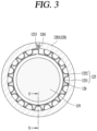
- FIG. 3 is a conceptual view of a journal bearing 124 in FIG. 2 viewed in an axial direction.
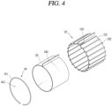
- FIG. 4 is an exploded perspective view of the journal bearing 124 in FIG. 3 .
- a turbo compressor according to the disclosure may include a housing 100, a motor part 120, a rotary shaft 119, an impeller 123, an impeller casing 110, a bearing housing 128, a thrust bearing 127, and a journal bearing 124.
- the housing 100 may be formed in a cylindrical shape.
- the housing 100 may define the appearance of the turbo compressor.
- Both sides of the housing 100 may be fastened to the impeller casing 110.
- An accommodation space may be defined inside the housing 100.
- the accommodation space of the housing 100 may be divided into a first space 117 and a second space 118.
- the first space 117 and the second space 118 may be partitioned by a barrier wall 116.
- the barrier wall 116 may protrude radially from an inner circumferential surface of the housing 100 toward the rotary shaft 119.
- the barrier wall 116 may extend along the inner circumferential surface of the housing 100 in a circumferential direction.
- the barrier wall 116 may be formed in a circular plate shape having a preset thickness.
- a shaft penetration hole may be formed through a central portion of the barrier wall 116 such that the rotary shaft 119 passes through it.
- the barrier wall 116 may be positioned radially apart from the rotary shaft 119 at a preset interval.
- the barrier wall 116 may be disposed to be biased from a longitudinal center of the housing 100 in one direction.
- the first space 117 may be formed to be open toward one side of the housing 100, and the second space 118 may be formed to be open toward another side of the housing 100.
- the first space 117 and the second space 118 may have different volumes from each other.
- the volume of the first space 117 may be smaller than the volume of the second space 118.
- the motor part 120 to be explained later may be received in the second space 118 that has a relatively large volume.
- a portion of a first bearing housing 1281, which will be described later, may be received in the first space 117.
- a second bearing housing 1282, which will be described later, may be received in the second space 118.
- the rotary shaft 119 may be horizontally disposed in the first space 117 and the second space 118, to axially pass through a radial center portion of the housing 100.
- the motor part 120 may include a stator 121 and a rotor 122.
- the stator 121 may include a stator core 1211 and a stator coil 1212.
- the stator core 1211 may be formed in a cylindrical shape by stacking a plurality of electrical steel sheets.
- the stator core 1211 may be provided with a plurality of teeth formed therein to protrude toward the rotary shaft 119 in the radial direction.
- a plurality of slots may be formed between the plurality of teeth.
- the plurality of teeth and the plurality of slots may be arranged alternately in the circumferential direction of the stator core 1211 and may be spaced apart from each other in the circumferential direction.
- the stator coil 1212 may be wound on the stator core 1211 through the slots 102.
- stator coil 1212 When power is applied to the stator coil 1212, a magnetic field may be generated around the stator coil 1212.
- the rotor 122 may be arranged inside the stator 121.
- the rotor 122 may be positioned apart from the stator 121 with an air gap therebetween.
- the rotor 122 may be mounted on the rotary shaft 119 to be rotatable relative to the stator 121.
- the rotor 122 may include a rotor core and permanent magnets 1221.
- the rotor core may be mounted to be rotatable together with the rotary shaft 119 or may be omitted.
- the permanent magnets 1221 may be mounted on the rotary shaft 119.
- the permanent magnets 1221 may be arranged on the rotary shaft 119 or the rotor core to radially overlap an inner surface of the stator 121 with an air gap. In the embodiment disclosed herein, the permanent magnets 1221 are shown mounted on the rotary shaft 119.
- a rotor support portion may be disposed on the rotary shaft 119.
- the rotor support portion may be positioned on an axial center of the rotary shaft 119.
- the rotor support portion may be formed to be recessed into or protrude from the rotary shaft 119 in the radial direction.
- the corresponding permanent magnet 1221 may be mounted to be received in the rotor support portion, or may be fixed between the plurality of rotor support portions so that its axial movement is limited by the protruded rotor support portions. In the embodiment disclosed herein, it is illustrated that the rotor support portions protrude radially from the rotary shaft 119, and the corresponding permanent magnet 1221 is fixedly positioned between the plurality of rotor support portions.
- the permanent magnet 1221 may be formed in a ring shape.
- the permanent magnet 1221 may have an inner diameter that is equal to a diameter of the rotary shaft 119.
- the permanent magnet 1221 may have an outer diameter that is smaller than an inner diameter of the stator core.
- the rotor 122 may rotate relative to the stator 121 by electromagnetic interaction between the stator 121 and the rotor 122.
- the rotary shaft 119 may transmit rotational force to an impeller 123 to be described later while rotating together with the rotor 122.
- the rotary shaft 119 may be supported at both ends by bearings.
- the bearings may include a first bearing and a second bearing.
- the first bearing may be configured to support one side of the rotary shaft 119.
- the first bearing may be disposed between the motor part 120 and a first-stage impeller 123 to be described later.
- the bearings may include a journal bearing 124 that supports a radial load of the rotary shaft 119 and a thrust bearing 127 that supports an axial load of the rotary shaft 119.
- the first bearing may include a first journal bearing 1241, a first thrust bearing 1271, and a second thrust bearing 1272.
- the second bearing may include a second journal bearing 1242.
- the bearing housing 128 may include a first bearing housing 1281 and a second bearing housing 1282.
- the first bearing housing 1281 may be configured to support the first bearing. However, the second thrust bearing 1272 may be supported on the barrier wall 116.
- the first bearing housing 1281 may be formed in a cylindrical shape.
- the first bearing housing 1281 may have a circular pocket formed radially inward.
- the first bearing housing 1281 may be positioned between a first impeller casing 111 to be described later and the barrier wall 116 of the housing 100. A portion of the first bearing housing 1281 may be accommodated in the first space 117 of the housing 100, and another portion of the first bearing housing 1281 may be accommodated inside the first impeller casing 111.
- the first bearing housing 1281 may be press-fitted to the inside of the first impeller casing 111 and the housing 100.
- a first shaft hole may be formed inside the first bearing housing 1281 so that the rotary shaft 119 passes through it.
- the first shaft hole may have a diameter greater than the rotary shaft 119.
- the first bearing may be mounted on the first bearing housing 1281.
- the first journal bearing 1241 may be mounted to be received radially inside the first bearing housing 1281.
- the first thrust bearing 1271 may be mounted on an axial rear surface of the first bearing housing 1281.
- a thrust runner 129 may be disposed on the rotary shaft 119.
- the thrust runner 129 may protrude radially from the rotary shaft 119 to the first space 117.
- the thrust runner 129 may rotate together with the rotary shaft 119.
- the second thrust bearing 1272 may be mounted on the barrier wall 116.
- the second thrust bearing 1272 may be arranged spaced apart from an opposite side of the first thrust bearing 1271 with the thrust runner 129 therebetween.
- the second thrust bearing 1252 may be arranged axially spaced apart from another axial side surface of the thrust runner 129.
- the second bearing housing 1282 may be configured to include a bearing receiving portion and a radial extension portion.
- a second shaft hole formed in a cylindrical shape is provided inside the bearing receiving portion.
- the rotary shaft 119 may pass axially through the second shaft hole.
- An outer circumferential surface of the bearing receiving portion may be inclined with respect to the axial direction.
- the second journal bearing 1242 may be mounted on an inner surface of the bearing receiving portion.
- the second journal bearing 1242 may be arranged radially spaced apart from the rotary shaft 119 with a gap therebetween.
- the radial extension portion may extend from an outer circumferential portion of the bearing receiving portion to protrude radially outward.
- the radial extension portion may extend in a circular plate shape along the circumferential direction.
- the radial extension portion may be coupled to the inside of another end of the housing 100.
- the bearing receiving portion may protrude axially from the radial extension portion toward the second space 118 of the housing 100.
- first journal bearing 1241 and the second journal bearing 1242 may support the radial load of the rotary shaft 119.
- the first thrust bearing 1271 and the second thrust bearing 1272 may support the axial load of the rotary shaft 119 with the thrust runner 129 therebetween.
- journal bearing 124 and the thrust bearing 127 may each be implemented as a gas foil bearing.
- the gas foil bearing is configured to support the rotary shaft 119 by means of a working fluid.
- the working fluid may be refrigerant, air, etc.
- the gas foil bearing may be arranged spaced apart from the rotary shaft 119 with a preset gap (air gap).
- a gas foil bearing may rotatably support the rotary shaft 119 by using a working fluid filled in the gap between the rotary shaft 119 and the bearing.
- the bearing according to the disclosure may be spaced apart from the rotary shaft 119, to thus rotatably support the rotary shaft 119 in a non-contact manner. Accordingly, as the rotary shaft 119 rotates at high speed, an air gap may be stably formed between the rotary shaft 119 and the bearing, and the center of the rotary shaft 119 may be positioned at the center of the bearing. When the rotation speed increases, pressure of the air gap may increase by centrifugal force, thereby improving a shaft support capacity and implementing a high-efficiency compressor without friction. Noise and wear may also be reduced, thereby extending the lifespan of the bearing.
- the bearing according to the disclosure does not require lubricant, so there is no need for lubricant replacement and maintenance costs.
- the gas foil bearing may be made of an elastic material.
- the gas foil bearing includes a bump foil 125 and a cover foil 126.
- the bump foil 125 may be formed in an embossed shape and have elasticity.
- the cover foil 126 may be disposed to cover the bump foil 125.
- the bump foil 125 may include a curved portion 1251 and a connecting portion 1252.
- the curved portion 1251 may be formed in a semicircular shape.
- the curved portion 1251 and the connecting portion 1252 may each be provided in plurality.
- the bump foil 125 may have a structure in which a thin steel plate is rolled into a cylindrical shape.
- the plurality of curved portions 1251 and connecting portions 1252 may be arranged alternately along the circumferential direction.
- the curved portion 1251 may be arranged to face an outer circumferential surface of the rotary shaft 119.
- the curved portion 1251 may be formed to be convex toward the rotary shaft 119.
- the connecting portion 1252 may be configured to connect the curved portions 1251 that are adjacent to each other in the circumferential direction.
- the connecting portion 1252 may be arranged to be contactable with the inner circumferential surface of the bearing housing 128.
- the connecting portion 1252 may circumferentially extend along the inner circumferential surface of the bearing housing 128.
- the bump foil 125 may include a bump fixing portion 1253.
- the bump fixing portion 1253 is provided on one end of the bump foil 125. Another end of the bump foil 125, which is cylindrically rolled, may be arranged adjacent to the bump fixing portion 1253.
- the bump fixing portion 1253 may be formed to be bent radially outward from the connecting portion 1252.
- a fixing groove 1283 for fixing the bump foil 125 may be formed in the inner circumferential surface of the bearing housing 128.
- the bump fixing portion 1253 may be inserted into the fixing groove 1283.
- the cover foil 126 may include a cover fixing portion 1261.
- the cover foil 126 may have a structure in which a thin steel plate is rolled into a cylindrical shape so that both ends are placed adjacent to each other.
- the cover fixing portion 1261 may be disposed on another end of the cover foil 126 that is rolled into the cylindrical shape.
- the cover fixing portion 1261 may be arranged to face the bump fixing portion 1253.
- the cover fixing portion 1261 may be inserted into the fixing groove 1283 to fix the cover foil 126 to the bearing housing 128.
- the bump foil 125 may be arranged to surround the cover foil 126.
- the cover foil 126 may extend in the circumferential direction to be in contact with a vertex of the curved portion 1251 formed in the semicircular shape that is convex toward the rotary shaft 119.
- the rotary shaft 119 may move radially to be in contact with the cover foil 126.
- the cover foil 126 may transmit force received from the rotary shaft 119 to the bump foil 125.
- the bump foil 125 may be deformed within an elastic range by the force transmitted through the cover foil 126.
- an extra space may be formed between the cover fixing portion 1261 and another end of the bump foil 125, so that the bump foil 125 and the cover foil 126 may be elastically deformed.
- An extra space may also be formed between the cover fixing portion 1261 and one end of the cover foil 126.
- the turbo compressor may compress refrigerant in multiple stages depending on the number of impellers 123.
- the turbo compressor is implemented as a two-stage compressor.
- the impeller 123 may be classified into a first impeller 1231 to an Nth impeller according to a compression order of refrigerant.
- the impeller 123 is shown as including a first impeller 1231 and a second impeller 1232.
- the first impeller 1231 may be named a first-stage impeller 123
- the second impeller 1232 may be named a second-stage impeller 123.
- first impeller 1231 and the second impeller 1232 are separately distinguished in the specification, a description of the configuration of the impeller 123 may also be applied to the first impeller 1231 and the second impeller 1232.
- a fluid such as refrigerant and/or air may be subjected to a first-stage compression in the first impeller 1231 and a second-stage compression in the second impeller 1232.
- the impeller 123 may be mounted on the rotary shaft 119 to be rotatable together with the rotary shaft 119.
- the impeller 123 may rotate by receiving force from the motor part 120 through the rotary shaft 119.
- the impeller 123 may suction a fluid such as refrigerant and compress the fluid such as the refrigerant while rotating together with the rotary shaft 119.
- a first impeller support portion and a second impeller support portion may be disposed on both ends of the rotary shaft 119.
- the first impeller support portion may have a diameter smaller than the diameter of the rotary shaft 119 and may protrude axially from one end of the rotary shaft 119.
- the first impeller support portion may be press-fitted to the inside of a hub 123a of the first impeller 1231.
- the second impeller support portion may have a diameter smaller than the diameter of the rotary shaft 119 and may protrude axially from another end of the rotary shaft 119.
- the second impeller support portion may be press-fitted to the inside of a hub 123a of the second impeller 1232.
- the impeller 123 may include a hub 123a and a plurality of blades 123b.
- the hub 123a may include a through hole formed through an inside thereof and the rotary shaft 119 may pass through the through hole.
- the hub 123a may be formed in a conical shape.
- An outer circumferential surface of the hub 123a may be formed to be inclined with respect to the axial direction.
- a diameter of the hub 123a may be formed to increase from one axial side of the hub 123a to another axial side of the hub 123a.
- the plurality of blades 123b may protrude spirally from the outer circumferential surface of the hub 123a.
- the plurality of blades 123b may be arranged spaced apart from each other in the circumferential direction of the hub 123a.
- the impeller 123 may suction gas such as refrigerant in the axial direction and discharge the suctioned gas in a centrifugal direction of the impeller 123.
- a first impeller casing 111 may be fastened to one side of the housing 100.
- An axial rear surface of the first impeller casing 111 may be covered with the first bearing housing 1281 received in one side of the housing 100.
- a second impeller casing 112 may be fastened to another side of the housing 100.
- An axial rear surface of the second impeller casing 112 may be covered with the second bearing housing 1282 received in another side of the housing 100.
- the axial rear surfaces of the first impeller casing 111 and the second impeller casing 112 refer to the downstream side of the impeller casing 110 based on a flow direction of refrigerant.
- the first impeller casing 111 may include a suction port 113a, 113b, a diffuser 114a, 114b, and a discharge port 115a, 115b.
- the suction port 113a, 113b may be formed through a center of the first impeller casing 111 in the axial direction. One side of the suction port 113a, 113b may communicate with the outside of the first impeller casing 111, and another side of the suction port 113a, 113b may communicate with the inside of the first impeller casing 111.
- the first impeller 1231 may be received inside the suction port 113a, 113b.
- the first impeller 1231 may be mounted on the first impeller support portion and may rotate together with the rotary shaft 119.
- the suction port 113a, 113b may be formed so that its diameter decreases from one axial side to another axial side. Accordingly, a flow rate of refrigerant that is suctioned through the suction port 113a, 113b may increase.
- the diffuser 114a, 114b may be formed to be axially recessed into the axial rear surface of the first impeller casing 111.
- the diffuser 114a, 114b may be formed inside the first impeller casing 111.
- the diffuser 114a, 114b may be arranged between the suction port 113a, 113b and the discharge port 115a, 115b.
- the diffuser 114a, 114b may be formed to extend in a spiral direction from the suction port 113a, 113b.
- the diffuser 114a, 114b may be connected to communicate with the suction port 113a, 113b and the discharge port 115a, 115b.
- the diffuser 114a, 114b may be formed so that a size of a passage (flow path) increases from the suction port 113a, 113b to the discharge port 115a, 115b.
- the diffuser 114a, 114b may increase pressure of refrigerant by converting kinetic energy of the refrigerant suctioned through the suction port 113a, 113b into pressure energy.
- the discharge port 115a, 115b may be disposed on an outer circumferential portion of the first impeller casing 111.
- the discharge port 115a, 115b may extend radially from the diffuser 114a, 114b.
- a discharge pipe may be formed to protrude outward from the outer circumferential portion of the first impeller casing 111.
- the discharge pipe may be connected such that one side thereof communicates with the discharge port 115a, 115b and another side communicates with the outside of the first impeller casing 111.
- the discharge pipe of the first impeller casing 111 may be connected to the suction port 113a, 113b of the second impeller casing 112 through a connection pipe (not illustrated).
- One part may be a suction part 111a, 112a.
- the suction part 111a, 112a may be formed to have a T-like cross-sectional shape.
- the suction part 111a, 112a may be configured with a radial portion extending in the radial direction and an axial portion extending in the axial direction.
- the suction port 113a, 113b may be formed inside the axial portion of the suction part 111a, 112a.
- Another part may be a diffuser part 111b, 112b.
- the diffuser part 111b, 112b may be formed to surround an outer circumference and a rear surface of the radial portion of the suction part 111a, 112a and an outer circumferential surface of the axial portion.
- the suction part 111a, 112a and the diffuser part 111b, 112b may be coupled to each other.
- the rear surface of the radial portion of the suction part 111a, 112a refers to a downstream surface based on a suction direction of refrigerant.
- a radial sealing member and an axial sealing member may be provided.
- the radial sealing member may be disposed between the bearing housing 128 and the impeller 123. In the embodiment disclosed herein, the radial sealing member is shown arranged between the first bearing housing 1281 and the impeller 123.
- the radial sealing member may be configured with a first radial sealing portion 130 and a second radial sealing portion 134.
- first radial sealing portion 130 may be arranged on one axial side surface of the first bearing housing 1281.
- the first radial sealing portion 130 may be formed integrally on one axial side surface of the first bearing housing 1281 or may be coupled to the one axial side surface of the first bearing housing 1281.
- the first radial sealing portion 130 is shown coupled to one axial side surface of the first bearing housing 1281.
- a sealing portion receiving groove 131 in which the first radial sealing portion 130 is received, may be formed to be axially recessed into the one axial side surface of the first bearing housing 1281.
- the first radial sealing portion 130 may include a plurality of sealing grooves 132 and a plurality of first land portions 133.
- the plurality of sealing grooves 132 may be formed to be axially recessed into one axial side surface (front surface) of the first radial sealing portion 130 in an opposite direction to the impeller 123.
- the plurality of sealing grooves 132 may extend along the circumferential direction of the first radial sealing portion 130.
- the front surface of the first radial sealing portion 130 may refer to a surface facing the impeller 123.
- the plurality of sealing grooves 132 may be arranged in a spaced manner in the radial direction of the first radial sealing portion 130.
- the plurality of sealing grooves 132 may be arranged to overlap the impeller 123 in the axial direction.
- the plurality of first land portions 133 may be arranged between the plurality of sealing grooves 132.
- the plurality of sealing grooves 132 and the plurality of first land portions 133 may be alternately arranged in the radial direction of the first radial sealing portion 130.
- Each of the plurality of sealing grooves 132 and the plurality of first land portions 133 may be formed in an annular shape. However, a radial width of the sealing groove 132 and a radial thickness of the first land portion 133 may be formed differently.
- a second radial sealing portion 134 may be disposed on another axial side surface (rear surface) of the first impeller 1231.
- the rear surface of the first impeller 1231 may be a surface facing the first radial sealing portion 130.
- the second radial sealing portion 134 may be arranged at a downstream side of the first impeller 1231 based on a flow direction of refrigerant.
- the second radial sealing portion 134 may rotate together with the first impeller 1231.
- the second radial sealing portion 134 may include a plurality of sealing protrusions 135.
- the plurality of sealing protrusions 135 may be formed to protrude axially from another axial side surface of the hub 123a of the first impeller 1231 toward the first radial sealing portion 130.
- the plurality of sealing protrusions 135 may be received in the plurality of sealing grooves 132, respectively.
- the sealing protrusion 135 may be received in the sealing groove 132, but may be arranged to be spaced apart from an inner surface of the sealing groove 132 with preset intervals in the axial direction and the radial direction.
- the sealing protrusion 135 may extend along the circumferential direction of the hub 123a and may be formed in an annular shape.
- the plurality of sealing protrusions 135 and the plurality of first land portions 133 may be arranged to overlap each other in the radial direction.
- the impeller 123 when the impeller 123 rotates, the plurality of blades 123b may rotate around the hub 123a, so that the impeller 123 may discharge refrigerant suctioned through a space between the plurality of blades 123b toward the diffuser 114a, 114b in the radial direction.
- the plurality of sealing protrusions 135 and first land portions 133 may act as flow resistance for the refrigerant, which flows from the diffuser 114a, 114b toward the downstream side of the impeller 123, thereby suppressing the refrigerant from flowing backward to a radial inside through a gap between the sealing groove 132 of the first radial sealing portion 130 and the rear surface of the impeller 123.
- the radial sealing member may also be equally applied between the second bearing housing 1282 and the second impeller 1232.
- the axial sealing member may be disposed between the second bearing housing 1282 and the second impeller casing 112.
- the axial sealing member may be configured with a first axial sealing portion 136 and a second axial sealing portion.
- the first axial sealing portion 136 may be disposed inside the diffuser part 111b, 112b of the second impeller casing 112.
- the first axial sealing portion 136 may be coupled between the second bearing housing 1282 and the diffuser part 111b, 112b of the second impeller casing 112.
- the first axial sealing portion 136 may include a plurality of sealing grooves.
- the plurality of sealing grooves may be formed to be radially recessed into an inner surface of the first axial sealing portion 136, more specifically, into an inner surface of the bearing receiving portion.
- the sealing groove may be formed in an annular shape.
- the sealing groove may extend circumferentially along an inner circumference of the first axial sealing portion 136.
- the plurality of sealing grooves may be disposed to be axially spaced apart from one another inside the first axial sealing portion 136.
- a plurality of second land portions may be positioned between the plurality of sealing grooves.
- the plurality of sealing grooves and the plurality of second land portions may be arranged alternately to be spaced apart from each other along the axial direction in the inner surface of the first axial sealing portion 136.
- the second axial sealing portion may be disposed on another side of the rotary shaft 119.
- the second axial sealing portion may rotate together with the first impeller 1231.
- the second axial sealing portion may be arranged to overlap the sealing groove in the radial direction to be received in the sealing groove.
- the second axial sealing portion may include a plurality of sealing protrusions.
- the plurality of sealing protrusions may be formed to protrude radially outward from an outer circumferential surface of the rotary shaft 119 toward the inner surfaces of the sealing grooves.
- the plurality of sealing protrusions may be formed in an annular shape.
- the plurality of sealing protrusions may be arranged axially spaced apart from one another on the rotary shaft 119.
- the plurality of sealing protrusions and the plurality of second land portions may be alternately arranged along the axial direction of the rotary shaft 119.
- the plurality of sealing protrusions and the plurality of second land portions may be arranged to be spaced apart from each other at a preset interval.
- the plurality of second land portions are positioned radially apart from the rotary shaft 119 at a preset interval.
- the plurality of sealing protrusions are positioned radially spaced apart from the inner surface of the first axial sealing portion 136 at a preset interval.
- the plurality of sealing protrusions and the plurality of second land portions may be arranged to overlap each other in the axial direction.
- the plurality of blades 123b may rotate around the hub 123a, so that the second impeller 1232 may axially suction refrigerant through a space between the plurality of blades 123b.
- the plurality of sealing protrusions and the plurality of second land portions may act as flow resistance of refrigerant, which flows through the gap between the first axial sealing portion 136 and the rotary shaft 119, thereby suppressing leakage of the refrigerant through the gap between the inner surface of the first axial sealing portion 136 and the rotary shaft 119.
- the axial sealing member may also be applied equally between the first bearing housing 1281 and one side of the rotary shaft 119.
- FIG. 5 is a cross-sectional view taken along the line V-V in FIG. 4 , which is also a conceptual view for explaining a journal bearing safety device 1 according to one embodiment.
- the disclosure may cope with an abnormal behavior due to an abnormal operation caused by external impact, liquid refrigerant, etc.
- the bump foil 125 of the journal bearing 124 may support a radial load by spring characteristics, but when subjected to an impact exceeding a certain level, the bump foil 125 undergoes plastic deformation.
- the turbo compressor according to the disclosure may include a journal bearing safety device having a structure that is capable of minimizing plastic deformation of the journal bearing 124 and suppressing damage to the rotary shaft 119.
- journal bearing 124 is shown implemented as a gas foil bearing.
- the journal bearing 124 may include a bump foil 125, a cover foil 126, a bump detachment suppression ring 141, and a stopper 143.
- the bump detachment suppression ring 141 may be formed in a shape of a ring with one side open.
- the bump detachment suppression ring 141 may include a ring body 1411 and an inner hole 1412.
- the ring body 1411 may define the exterior of the bump detachment suppression ring 141.
- the ring body 1411 may be formed in a circular ring shape. One side of the ring body 1411 may be open in the radial direction.
- the ring body 1411 may have a circular cross-sectional shape.
- the circular inner hole 1412 may be formed inside the ring body 1411. A diameter of the inner hole 1412 may be larger than a diameter of the rotary shaft 119.
- the bump detachment suppression ring 141 may be formed in a C-like shape and may thusly be named a C-ring.
- the bump detachment suppression ring 141 may be mounted on the first bearing housing 1281.
- the bump detachment suppression ring 141 may be configured to suppress the bump foil 125 and the cover foil 126 from being detached in the axial direction.
- the bump detachment suppression ring 141 may be arranged on one side of the bump foil 125.
- the bump detachment suppression ring 141 may be disposed to protrude radially inward based on the inner circumferential surface of the first bearing housing 1281 on which the bump foil 125 is mounted.
- a ring groove 142 may be formed in one side of the first bearing housing 1281 to be concave in the radial direction.
- the ring groove 142 may be formed continuously in the circumferential direction along the inner circumferential surface of the first bearing housing 1281.
- the bump detachment suppression ring 141 may be coupled by being inserted into the ring groove 142. A portion of the bump detachment suppression ring 141 may be received in the ring groove 142, and the bump detachment suppression ring 141 may be formed to protrude from the ring groove 142 toward the rotary shaft 119.
- the stopper 143 may be formed to protrude from the inner circumferential surface of the first bearing housing 1281 toward the rotary shaft 119.
- the stopper 143 may be positioned axially opposite to the bump detachment suppression ring 141.
- the journal bearing 124 may be disposed between the stopper 143 and the bump detachment suppression ring 141.
- the stopper 143 and the bump detachment suppression ring 141 may be arranged to overlap a portion of the bump foil 125 in the axial direction, thereby suppressing the journal bearing 124 from moving in the axial direction.
- a protrusion height h1 of the stopper 143 may be lower than a bump height H of the bump foil 125 based on the inner circumferential surface of the first bearing housing 1281 on which the journal bearing 124 is mounted.
- the bump height H of the bump foil 125 refers to a distance from the inner circumferential surface of the first bearing housing 1281 to a vertex of the curved portion 1251 of the bump foil 125 in the radial direction toward the rotary shaft 119.
- the protrusion height h1 of the stopper 143 refers to a length from the inner circumferential surface of the first bearing housing 128 to the top of the stopper 143 in the radial direction toward the rotary shaft 119.
- the protrusion height h1 of the stopper 143 may limit the maximum elastic deformation of the bump foil 125 in the radial direction.
- the protrusion height h1 of the stopper 143 may also limit the radial movement distance of the rotary shaft 119.
- the stopper 143 may allow elastic deformation of the bump foil 125 in the radial direction within a certain range, but suppress damage due to small deformation of the journal bearing even when an impact exceeding a certain level is applied to the journal bearing 124.
- the protrusion height h1 of the stopper 143 may be higher than a protrusion height h2 of the bump detachment suppression ring 141.
- the protrusion height h2 of the bump detachment suppression ring 141 refers to a length from the inner circumferential surface of the first bearing housing 1281 to the highest point of a circular cross-section of the ring body 1411, which protrudes outwardly from the ring groove 142.
- the rotary shaft 119 may be brought into contact with the bump detachment suppression ring 141 before in contact with the stopper 143, during the radial movement of the rotary shaft 119.
- the rotary shaft 119 may be damaged, for example, scratched, due to the contact with the bump detachment suppression ring 141.
- the stopper 143 may suppress damage to the rotary shaft 119 by suppressing the contact between the rotary shaft 119 and the bump detachment suppression ring 141 during the radial movement of the rotary shaft 119.
- the stopper 143 may include a wear-resistant coating layer made of polytetrafluoroethylene (PTFE), etc.
- PTFE polytetrafluoroethylene
- the wear-resistant coating layer By forming the wear-resistant coating layer on an outer surface of the stopper 143, self-lubricating characteristics may be secured, and thus the stopper 143 may not cause damage to the rotary shaft 119 even when it is in contact with the rotary shaft 119.
- the protrusion height h1 of the stopper 143 may be formed in the range of 40 to 50% of the bump height H.
- the bump foil may be elastically deformed in the range of 50 to 60% of the bump height H.
- the protrusion height h1 of the stopper 143 is less than 40% of the bump height H and is lower than the protrusion height h2 of the bump detachment suppression ring 141, there may be a problem in that the rotary shaft 119 is damaged, due to being brought into contact with the bump detachment suppression ring 141 before in contact with the stopper 143, during the radial movement of the rotary shaft 119.
- the stopper 143 may be formed integrally with the first bearing housing 1281 or may be provided separately from the first bearing housing 1281 and coupled to the first bearing housing 1281. In the embodiment disclosed herein, the stopper 143 is shown formed integrally with the first bearing housing 1281.
- the bump detachment suppression ring 141 and stopper 143 may be applied not only to the journal bearing 124 of the first bearing but also to the journal bearing 124 of the second bearing. Since the journal bearing 124 of the second bearing is equal or similar to the journal bearing 124 of the first bearing, a redundant description will be omitted.
- the stopper 143 may be configured with a first stopper and a second stopper.
- the first stopper may be disposed on one side of the journal bearing 124, and the second stopper may be disposed on another side of the journal bearing 124.
- the journal bearing 124 may be arranged between the first stopper and the second stopper.
- the first stopper and the second stopper may be formed to protrude from the inner circumferential surface of the bearing housing 128 toward the rotary shaft 119.
- the first stopper and the second stopper may come into contact with the rotary shaft 119.
- the first stopper and the second stopper may limit the radial movement range of the rotary shaft 119 to within the elastic deformation range of the journal bearing 124.
- the first stopper and the second stopper may suppress the journal bearing 124 from being axially separated from the inner circumferential surface of the bearing housing 128.
- the bump detachment suppression ring 141 may be omitted.
- the first stopper and the second stopper may each have an outer surface on which a wear-resistant coating layer such as PTFE is formed.
- FIG. 6 is a conceptual view illustrating that a journal bearing safety device 2 according to another embodiment is mounted on the first bearing housing 1281 when viewed in an axial direction.
- FIG. 7 is a cross-sectional view taken along the line VII-VII in FIG. 6 .
- FIG. 8 is an enlarged view of a part VIII in FIG. 7 .
- This embodiment differs from the embodiment of FIG. 5 in that a stop ring 144 is mounted on the first bearing housing 1281.
- the stop ring 144 may be formed in a circular ring shape.
- the stop ring 144 may be formed in the shape of a closed loop.
- the stop ring 144 may extend continuously along the circumferential direction.
- the stop ring 144 includes a stop ring body 1411 formed in a shape of a closed loop, and an axial through hole formed inside the stop ring body 1411.
- the axial through hole of the stop ring 144 may have a diameter larger than the diameter of the rotary shaft 119.
- the stop ring body 1411 may have a circular cross-sectional shape.
- a first ring mounting groove 1451 and a second ring mounting groove 1452 may be concavely formed in the first bearing housing 1281.
- the first and second ring mounting grooves 1451 and 1452 may be axially spaced apart from each other in the inner circumferential surface of the first bearing housing 1281, on which the journal bearing 124 is mounted.
- the first stop ring 1441 and the second stop ring 1441 may be mounted in the first ring mounting groove 1451 and the second ring mounting groove 1452, respectively.
- a protrusion height h1 of the stop ring 144 may be lower than the bump height H of the gas foil bearing (the bump foil 125) based on the inner circumferential surface of the first bearing housing 1281, on which the journal bearing 124 is mounted.
- the stop ring 131 may further protrude toward the rotary shaft 119 than the inner circumferential surface of the first bearing housing 100, thereby limiting the journal bearing 124 from moving in the axial direction.
- the stop ring 131 may limit the radial movement distance of the rotary shaft 119 to within the elastic deformation range of the journal bearing 124 even when an impact is applied to the bump foil 125 of the journal bearing 124 due to the radial movement of the rotary shaft 119.
- first and second stop rings 1441 and 1442 are shown arranged on both sides of the journal bearing 124.
- the disclosure is not limited to this, and the stop ring 144 may be disposed on one side of the journal bearing 124, and the bump detachment suppression ring 141 may be disposed on another side of the journal bearing 124.
- the protrusion height h1 of the stop ring 131 may preferably be 40 to 50% of the bump height H of the bump foil 125 of the journal bearing 124.
- a wear-resistant coating layer may be formed on an outer surface of the stop ring 131.
- the ring mounting groove 1451, 1452 may be positioned adjacent to one end of the inner circumferential surface of the bearing housing 128.
- the first ring mounting groove 1451 may be formed in a front end portion of the inner circumferential surface of the bearing housing 128 facing the impeller 123, and the second ring mounting groove 1452 may be formed in a rear end portion of the inner circumferential surface of the bearing housing 128 facing an opposite direction to the impeller 123.
- the stop ring 131 may be easily assembled into or disassembled from the ring mounting groove 1451, 1452.
- a chamfer portion 146 may be formed on one end of the inner circumferential surface of the bearing housing 128.
- the ring mounting groove 1451, 1452 may be disposed adjacent to the chamfer portion 146. Through this, the stop ring 131 may be easily assembled into and disassembled from the ring mounting groove 1451, 1452 through the chamfer portion 146.
- a radial sealing portion receiving groove 131 for receiving the first radial sealing portion 130 may be formed in the front surface of the first bearing housing 1281.
- An O-ring mounting groove 148 may be formed in an inner surface of the radial sealing portion receiving groove 131.
- An O-ring may be mounted in the O-ring mounting groove 148 to maintain airtightness between the first radial sealing portion 130 and the first bearing housing 1281.
- a fastening hole 149 may be formed in an outer circumferential portion of the first bearing housing 1281.
- the fastening hole 149 may be formed through the first bearing housing 1281 in the axial direction.
- a fastening member such as a screw may be fastened through the fastening hole 149.
- the fastening member may fasten the first bearing housing 1281 to the housing 100.
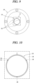
- FIG. 9 is a conceptual view illustrating that a journal bearing safety device 3 according to still another embodiment is mounted on a first bearing housing 1281 when viewed in an axial direction.
- FIG. 10 is an enlarged view of a part X in FIG. 9 .
- This embodiment differs from the embodiments of FIGS. 1 to 8 in that a ball bearing 150 is used as a safety device to suppress damage to the journal bearing 124.
- the ball bearing 150 may be formed in a spherical shape.
- the ball bearing 150 may be provided in plurality.
- a ball receiving groove 151 may be formed in the inner circumferential surface of the first bearing housing 1281.
- the ball receiving groove 151 may be formed to surround and support the ball bearing 150.
- the ball receiving groove 151 may be provided in plurality.
- the plurality of ball bearings 150 may be configured with a first ball bearing 1501 and a second ball bearing 1502.
- the first and second ball bearings 1501 and 1502 may be axially spaced apart from each other on the inner circumferential surface of the first bearing housing 1281 with the journal bearing 124 interposed therebetween.
- the plurality of ball bearings 150 may be arranged at uniform intervals along the circumferential direction.
- the ball bearing 150 may be provided by three sets, each of which includes the first ball bearing 1501 and the second ball bearing 1502.
- the three sets of ball bearings 150 may be arranged apart from one another at an interval of 120 degrees in the circumferential direction.
- FIG. 11 is a conceptual view illustrating that a journal bearing safety device 4 according to still another embodiment is mounted on the first bearing housing 1281 when viewed in an axial direction.
- FIG. 12 is an enlarged view of a part XII in FIG. 11 .
- This embodiment differs from the embodiments of FIGS. 1 to 8 in that a needle bearing 152 is used as a safety device to suppress damage to the journal bearing 124.
- the needle bearing 152 may be formed in the shape of a cylindrical roller whose length is long compared to its diameter.
- the needle bearing 152 may be provided in plurality.
- the plurality of needle bearings 152 may be configured with a first needle bearing 1521 and a second needle bearing 1522.
- the first and second needle bearings 1521 and 1522 may be axially spaced apart from each other on the inner circumferential surface of the first bearing housing 1281 with the journal bearing 124 interposed therebetween.
- a needle receiving groove 153 may be formed in the inner circumferential surface of the first bearing housing 1281.
- the needle receiving groove 153 may be formed to surround and support the needle bearing 152.
- the needle receiving groove 153 may be provided in plurality.
- the needle bearing 152 may be provided by a plurality of sets, each of which includes a first needle bearing 1521 and a second needle bearing 1522.
- the plurality of needle bearings 152 may be arranged at uniform intervals along the circumferential direction.
- the stop ring 131, the ball bearing 150, and the needle bearing 152 of the journal bearing safety devices have been described as being arranged on one side and the another side of the journal bearing 124, respectively, but any one of the stop ring 131, the ball bearing 150, and the needle bearing 152 and the bump detachment suppression ring may be arranged on one side and another side of the journal bearing 124, respectively.
- the journal bearing safety device may alternatively be configured by a combination of two different safety devices that are selected from among the stopper 143, the stop ring 131, the ball bearing 150, and the needle bearing 152.
- the journal bearing 124 may include a gas foil bearing mounted on the inner circumferential surface of the bearing housing 128, and may support the radial load of the rotary shaft 119 while forming an air gap from the rotary shaft 119.
- the journal bearing safety device may be provided on the inner circumferential surface of the bearing housing 128.
- the journal bearing safety device may be configured to limit the radial movement range of the rotary shaft 119 to within the elastic deformation range of the journal bearing 124.
- the stopper 143 may be formed to protrude from the inner circumferential surface of the bearing housing 128 toward the rotary shaft 119.
- the stopper 143 may be in contact with the rotary shaft 119 to limit the radial movement of the rotary shaft 119. Accordingly, the stopper 143 may limit the radial movement distance of the rotary shaft 119, thereby suppressing plastic deformation of the journal bearing 124 even when the rotary shaft 119 exhibits abnormal behavior due to an abnormal operation, which is caused by external impact or liquid refrigerant, while the journal bearing 124 supports the radial load of the rotary shaft 119.
- stopper 143 protrudes integrally from the inner circumferential surface of the bearing housing 128, there is no need to assemble additional components to suppress damage to the journal bearing 124. This may result in reducing the number of components and assembly processes, and also greatly reducing manufacturing costs.
- stopper 143 may form a structure protruding from the inner circumferential surface of the bearing housing 128, thereby improving durability through structural simplification.
- the protrusion height h1 of the stopper 143 protruding from the inner circumferential surface of the bearing housing 128 may be lower than the bump height H from the inner circumferential surface of the bearing housing 128 to the vertex of the curved portion 1251 of the gas foil bearing in the radial direction, and may be higher than the height h2 of the bump detachment suppression ring 141 protruding from the ring groove 142 toward the rotary shaft 119 based on the inner circumferential surface of the bearing housing 128.
- the radial movement of the rotary shaft 119 may be stopped by the stopper 143 before being in contact with the bump detachment suppression ring 141, thereby suppressing damage to the rotary shaft 119 due to the contact between the rotary shaft 119 and the bump detachment suppression ring 141.
- journal bearing safety device stop rings 131, ball bearings 150, and needle bearings 152 may be applied.
- Grooves may be formed in the inner circumferential surface of the bearing housing 128 such that the stop ring 131, the ball bearing 150, and the needle bearing 152 are coupled.
- the grooves may be arranged adjacent to the front or rear end of the inner circumferential surface of the bearing housing 128, and thus the stop ring 131, ball bearing 150, and needle bearing 152 may be easily assembled into or disassembled from the grooves.
- the ball bearings 150 and the needle bearings 152 may be spaced apart circumferentially along the inner circumferential surface of the bearing housing 128. Accordingly, the ball bearing 150 and the needle bearing 152 may have smaller contact areas with the rotary shaft 119 than the stop ring 131 extending circumferentially along the inner circumferential surface of the bearing housing 128.
- the ball bearing 150 or the needle bearing 152 may reduce the contact area through a point-contact or line-contact with the rotary shaft 119, thereby minimizing damages to the journal bearing 124 and the rotary shaft 119.
- the stopper 143, the stop ring 131, the ball bearing 150, and the needle bearing 152 may each have a surface on which the wear-resistant coating layer is formed, thereby minimizing damages to the journal bearing 124 and the rotary shaft 119 due to the contact with the rotary shaft 119.
- the stopper 143, the stop ring 131, the ball bearing 150, and the needle bearing 152 may also limit the radial movement range of the rotary shaft 119 to within the elastic deformation range of the journal bearing 124, thereby facilitating alignment between the journal bearing 124 and the rotary shaft 119.
- FIG. 13 is a conceptual view for explaining the configuration of a turbo compressor according to another embodiment.
- a turbo compressor according to the disclosure may include a housing 200, a motor part 220, a rotary shaft 219, an impeller 228, an impeller casing 211, 212, a bearing housing 128, a thrust bearing 227, and a journal bearing 224.
- the housing 200 may be formed in a cylindrical shape.
- the housing 200 may define the appearance of the turbo compressor.
- Both sides of the housing 200 may be fastened to the impeller casing 211, 212.
- An accommodation space may be defined inside the housing 200.
- the accommodation space of the housing 200 may be divided into a first space 217 and a second space 218.
- the first space 217 and the second space 218 may be partitioned by a barrier wall 216.
- the barrier wall 216 may protrude radially from an inner circumferential surface of the housing 200 toward the rotary shaft 219.
- the barrier wall 216 may extend along the inner circumferential surface of the housing 200 in a circumferential direction.
- the barrier wall 216 may be formed in a circular plate shape having a preset thickness.
- a shaft penetration hole may be formed through a central portion of the barrier wall 216 such that the rotary shaft 219 passes through it.
- the barrier wall 216 may be positioned radially apart from the rotary shaft 219 at a preset interval.
- the barrier wall 216 may be disposed to be biased from a longitudinal center of the housing 200 in one direction.
- the first space 217 may be formed to be open toward one side of the housing 200, and the second space 218 may be formed to be open toward another side of the housing 200.
- the first space 217 and the second space 218 may have different volumes from each other.
- the volume of the first space 217 may be smaller than the volume of the second space 218.
- the motor part 220 to be explained later may be received in the second space 218 that has a relatively large volume.
- a portion of a first bearing housing 2281, which will be described later, may be received in the first space 217.
- a second bearing housing 2282, which will be described later, may be received in the second space 218.
- the rotary shaft 219 may be horizontally disposed in the first space 217 and the second space 218, to axially pass through a radial center portion of the housing 200.
- the motor part 220 includes a stator 221 and a rotor 222.
- the stator 221 may include a stator core 2211 and a stator coil 2212.
- the stator core 2211 may be formed in a cylindrical shape by stacking a plurality of electrical steel sheets.
- the stator core 2211 may be provided with a plurality of teeth formed therein to protrude toward the rotary shaft 219 in the radial direction.
- a plurality of slots may be formed between the plurality of teeth.
- the plurality of teeth and the plurality of slots may be arranged alternately in the circumferential direction of the stator core 2211 and may be spaced apart from each other in the circumferential direction.
- the stator coil 2212 may be wound on the stator core 2211 through the slots 102.
- stator coil 2212 When power is applied to the stator coil 2212, a magnetic field may be generated around the stator coil 2212.
- the rotor 222 may be arranged inside the stator 221.
- the rotor 222 may be positioned apart from the stator 221 with an air gap therebetween.
- the rotor 222 may be mounted on the rotary shaft 219 to be rotatable relative to the stator 221.
- the rotor 222 may include a rotor core and permanent magnets 2221.
- the rotor core may be mounted to be rotatable together with the rotary shaft 219 or may be omitted.
- the permanent magnets 2221 may be mounted on the rotary shaft 219.
- the permanent magnets 2221 may be arranged on the rotary shaft 219 or the rotor core to radially overlap an inner surface of the stator 221 with an air gap. In the embodiment disclosed herein, the permanent magnets 2221 are shown mounted on the rotary shaft 219.
- a rotor support portion may be disposed on the rotary shaft 219.
- the rotor support portion may be positioned on an axial center of the rotary shaft 219.
- the rotor support portion may be formed to be recessed into or protrude from the rotary shaft 219 in the radial direction.
- the corresponding permanent magnet 2221 may be mounted to be received in the rotor support portion, or may be fixed between the plurality of rotor support portions so that its axial movement is limited by the protruded rotor support portions. In the embodiment disclosed herein, it is illustrated that the rotor support portions protrude radially from the rotary shaft 219, and the corresponding permanent magnet 2221 is fixedly positioned between the plurality of rotor support portions.
- the permanent magnet 2221 may be formed in a cylindrical ring shape.
- the permanent magnet 2221 may have an inner diameter that is equal to a diameter of the rotary shaft 219.
- the permanent magnet 2221 may have an outer diameter that is smaller than an inner diameter of the stator core.
- the rotor 222 may rotate relative to the stator 221 by electromagnetic interaction between the stator 221 and the rotor 222.
- the rotary shaft 219 may transmit rotational force to an impeller 223 to be described later while rotating together with the rotor 222.
- the rotary shaft 219 may be supported at both ends by bearings.
- the bearings may include a first bearing and a second bearing.
- the first bearing may be configured to support one side of the rotary shaft 219.
- the first bearing may be disposed between the motor part 220 and a first-stage impeller to be described later.
- the first-stage impeller may be called a first impeller 2231.
- the second bearing may be configured to support the other side of the rotary shaft 219.
- the second bearing may be disposed between the motor part 220 and a second-stage impeller to be described later.
- the second-stage impeller may be called a second impeller 2232.
- the bearings may include a journal bearing 224 that supports a radial load of the rotary shaft 219, and a thrust bearing 227 that supports an axial load of the rotary shaft 219.
- the first bearing may include a first journal bearing 2241, a first thrust bearing 2271, and a second thrust bearing 2272.
- the second bearing may include a second journal bearing 2242.
- the bearing housing 228 may include a first bearing housing 2281 and a second bearing housing 2282.
- the first bearing housing 2281 may be configured to support the first bearing. However, the second thrust bearing 2272 may be supported on the barrier wall 216.
- the first bearing housing 2281 may be formed in a cylindrical shape.
- the first bearing housing 2281 may have a circular pocket formed radially inward.
- the first bearing housing 2281 may be positioned between a first impeller casing 211 to be described later and the barrier wall 216 of the housing 200. A portion of the first bearing housing 2281 may be accommodated in the first space 217 of the housing 200, and another portion of the first bearing housing 2281 may be accommodated inside the first impeller casing 211.
- the first bearing housing 2281 may be press-fitted to the inside of the first impeller casing 211.
- a first shaft hole may be formed inside the first bearing housing 2281 so that the rotary shaft 219 passes through it.
- the first shaft hole may have a diameter larger than the rotary shaft 219.
- the first bearing may be mounted on the first bearing housing 2281.
- the first journal bearing 2241 may be mounted to be received radially inside the first bearing housing 2281.
- the second bearing housing 2282 may be configured to include a bearing receiving portion and a radial extension portion.
- a second shaft hole formed in a cylindrical shape may be provided inside the bearing receiving portion.
- the rotary shaft 219 may pass axially through the second shaft hole.
- An outer circumferential surface of the bearing receiving portion may be inclined with respect to the axial direction.
- the second journal bearing 2242 may be mounted on an inner surface of the bearing receiving portion.
- the second journal bearing 2242 may be arranged radially spaced apart from the rotary shaft 219 with a gap therebetween.
- the radial extension portion may extend from an outer circumferential portion of the bearing receiving portion to protrude radially outward.
- the radial extension portion may extend in a circular plate shape along the circumferential direction.
- the radial extension portion may be coupled to the inside of another end of the housing 200.
- the bearing receiving portion may protrude axially from the radial extension portion toward the second space 218 of the housing 200.
- first journal bearing 2241 and the second journal bearing 2242 may support the radial load of the rotary shaft 219.
- the first thrust bearing 2271 may be mounted on an axial rear surface of the first bearing housing 2281.
- a thrust runner 229 may be disposed on the rotary shaft 219.
- the thrust runner 229 may protrude radially from the rotary shaft 219 to the first space 217.
- the thrust runner 229 may rotate together with the rotary shaft 219.
- the first thrust bearing 2271 may be arranged axially spaced apart at an interval from one axial side surface of the thrust runner 229.
- the second thrust bearing 2272 may be mounted on the barrier wall 216.
- the second thrust bearing 2272 may be arranged spaced apart from an opposite side of the first thrust bearing 2271 with the thrust runner 229 therebetween.
- the second thrust bearing 2272 may be arranged axially spaced apart at an interval from another axial side surface of the thrust runner 229.
- the first thrust bearing 2271 and the second thrust bearing 2272 may support the axial load of the rotary shaft 219 with the thrust runner 229 therebetween.
- journal bearing 224 and the thrust bearing 227 may each be implemented as a gas foil bearing.
- the gas foil bearing may be configured to support the rotary shaft 219 by means of a working fluid.
- the working fluid may be refrigerant, air, etc.
- the working fluid may be refrigerant.
- the gas foil bearing may be arranged spaced apart from the rotary shaft 219 with a preset gap (air gap).
- a gas foil bearing may rotatably support the rotary shaft 219 by using a working fluid filled in the gap between the rotary shaft 219 and the bearing.
- the bearing according to the disclosure may be spaced apart from the rotary shaft 219, to thus rotatably support the rotary shaft 219 in a non-contact manner. Accordingly, as the rotary shaft 219 rotates at high speed, an air gap may be stably formed between the rotary shaft 219 and the bearing, and the center of the rotary shaft 219 may be aligned with the center of the bearing. When the rotation speed increases, pressure of the air gap may increase by centrifugal force, thereby improving a shaft support capacity and implementing a high-efficiency compressor without friction. Noise and wear may also be reduced, thereby extending the lifespan of the bearing.
- the bearing according to the disclosure does not require lubricant, so there is no need for lubricant replacement and maintenance costs.
- FIG. 14 is a conceptual view of a thrust bearing 227 in FIG. 13 viewed in an axial direction.
- FIG. 15 is a cross-sectional view taken along the line XV-XV (curve in a circumferential direction) in FIG. 14 .
- the thrust bearing 227 may be configured as a gas foil bearing.
- the thrust bearing 227 may be arranged to overlap the thrust runner 229 in the axial direction.
- the thrust bearing 227 may be configured with a first thrust bearing 2271 and a second thrust bearing 2272 according to installation positions.
- the first thrust bearing 2271 may be mounted on the rear surface of the first bearing housing 2281.
- the front surface of the first bearing housing 2281 may be positioned toward the first impeller 2231, and the rear surface of the first bearing housing 2281 may be positioned toward the thrust runner 229.
- the second thrust bearing 2272 may be mounted on a front surface of the barrier wall 216.
- the front surface of the barrier wall 216 may be positioned toward the thrust runner 229, and the rear surface of the barrier wall 216 may be positioned toward the motor part 220.
- the first thrust bearing 2271 and the second thrust bearing 2272 may be arranged axially apart from the thrust runner 229 at preset intervals.
- thrust bearing 227 will be equally applied to the first thrust bearing 2271 and the second thrust bearing 2272.
- the thrust bearing 227 may include a bump foil 2273, a cover foil 2274, and a bearing plate 2278.
- the bump foil 2273 may be an elastic structure.
- the bump foil 2273 may be configured by forming a metal film in an embossed shape.
- One side of the bump foil 2273 may be fixed to the bearing plate 2278, and another side of the bump foil 2273 may be a free end.
- the bump foil 2273 may be configured with a plurality of curved portions 2273a and a plurality of connecting portions 2273b.
- the curved portion 2273a may be formed in an arcuate shape or a semicircular shape.
- the connecting portion 2273b may be formed in a flat shape.
- the connecting portion 2273b may be configured to connect one end and another end of two curved portions 2273a which are adjacent to each other.
- the plurality of curved portions 2273a and the plurality of connecting portions 2273b may be arranged alternately along one direction.
- the plurality of curved portions 2273a and connecting portions 2273b may be formed as one body.
- the plurality of curved portions 2273a and the plurality of connecting portions 2273b are shown alternately arranged along the circumferential direction of the thrust bearing 227.
- the plurality of curved surfaces 2273a may be formed with the same radius.
- the plurality of curved portions 2273a may be formed convexly in the same direction.
- the plurality of curved portions 2273a may be formed convexly toward the cover foil 2274 on the bearing plate 2278.
- a direction in which the plurality of curved portions 2273a are formed convexly may be determined depending on a direction in which the bearing supports an axial load.
- the curved portion 2273a may be formed convexly in the axial direction, and as for the journal bearing, the curved portion 2273a may be formed convexly in the radial direction.
- the curved portion 2273a of the thrust bearing 227 may be formed to be convex in the axial direction.
- the cover foil 2274 may be disposed to cover the bump foil 2273.
- the cover foil 2274 may be named a top foil in that it is positioned to be contactable with the highest point of the bump foil 2273.
- the cover foil 2274 may be arranged to face the thrust runner 229 and to be axially spaced apart from the thrust runner 229.
- the cover foil 2274 may include a cover extension portion 2275, a cover inclined portion 272, and a cover fixing portion 2277.
- the cover extension portion 2275 may be positioned to be contactable with the highest point of the curved portion 2273a of the bump foil 2273.
- the cover fixing portion 2277 may be formed in a flat shape to fix the cover foil 2274 to the base plate.
- the cover inclined portion 2276 may be formed to be inclined at a preset angle with respect to the bearing plate 2278 to connect the cover extension portion 2275 and the cover fixing portion 2277.
- the bearing plate 2278 may be configured to fix the thrust bearing 227 to the first bearing housing 2281 or the barrier wall 216.
- the cover fixing portion 2277 of the cover foil 2274 may be fixed to the bearing plate 2278, and the cover extension portion 2275 of the cover foil 2274 may be a free end.
- the bearing plate 2278 may be formed as a circular plate.
- a through hole may be formed through the bearing plate 2278 so that the rotary shaft 219 may be inserted therethrough.
- the through hole of the bearing plate 2278 may have a diameter larger than the diameter of the rotary shaft 219.
- the cover foils 2274 may each be formed in a fan shape to have a size slightly smaller than 1/6 of the bearing plate 2278.
- the plurality of cover foils 2274 may be spaced apart in the circumferential direction of the bearing plate 2278, and one side of each cover foil 2274 may be fixed to the bearing plate 2278.
- the size of the cover foil 2274 is not limited thereto.
- the plurality of bump foils 2273 may be positioned inside the cover foils 2274 divided into six equal parts along the circumferential direction of the bearing plate 2278.
- the bump foils 2273 may extend in the circumferential direction of the bearing plate 2278.
- the plurality of bump foils 2273 may be disposed spaced apart from one another in the radial direction of the bearing plate 2278. However, the bump foil 2273 may be formed to correspond to the size of the cover foil 2274, and one bump foil 2273 may be provided for each cover foil 2274.
- the first thrust bearing 2271 and the second thrust bearing 2272 may rotatably support the axial load of the rotary shaft 219 by utilizing elastic force of the bump foil 2273.
- the turbo compressor may compress refrigerant in multiple stages depending on the number of impellers 128.
- the turbo compressor is implemented as a two-stage compressor.
- the impeller 223 may be classified into a first impeller 2231 to an Nth impeller according to a compression order of refrigerant.
- the impeller 223 is shown including a first impeller 2231 and a second impeller 2232.
- the first impeller 2231 may be named a first-stage impeller 123
- the second impeller 2232 may be named a second-stage impeller.
- first impeller 2231 and the second impeller 2232 are separately distinguished in the specification, a description of the configuration of the impeller 223 may also be applied to the first impeller 2231 and the second impeller 2232.
- a fluid such as refrigerant and/or air may be subjected to a first-stage compression in the first impeller 2231 and a second-stage compression in the second impeller 2232.
- the impeller 223 may be mounted on the rotary shaft 219 to be rotatable together with the rotary shaft 219.
- the impeller 223 may rotate by receiving force from the motor part 220 through the rotary shaft 219.
- the impeller 223 may suction a fluid such as refrigerant and compress the fluid such as the refrigerant during rotation together with the rotary shaft 219.
- a first impeller support portion and a second impeller support portion may be disposed on both ends of the rotary shaft 219.
- the first impeller support portion may have a diameter smaller than the diameter of the rotary shaft 219 and may protrude axially from one end of the rotary shaft 219.
- the first impeller support portion may be press-fitted to the inside of a hub 223a of the first impeller 2231.
- the second impeller support portion may have a diameter smaller than the diameter of the rotary shaft 219 and may protrude axially from another end of the rotary shaft 219.
- the second impeller support portion may be press-fitted to the inside of a hub 223a of the second impeller 2232.
- the impeller 223 may include a hub 223a and a plurality of blades 223b.
- the hub 223a may include a through hole formed through an inside thereof and the rotary shaft 219 may pass through the through hole.
- the hub 223a may be formed in a conical shape.
- An outer circumferential surface of the hub 223a may be formed to be inclined with respect to the axial direction.
- the hub 223a may be formed such that a diameter thereof increases from the front end of the hub 223a to the rear end in the axial direction with respect to a suction direction of a working fluid.
- the plurality of blades 223b may protrude spirally from the outer circumferential surface of the hub 223a.
- the plurality of blades 223b may be arranged spaced apart from each other in the circumferential direction of the hub 223a.
- the impeller 223 may suction gas such as refrigerant in the axial direction and discharge the suctioned gas in a centrifugal direction of the impeller 223.
- a first impeller casing 211 may be fastened to one side of the housing 200.
- An axial rear surface of the first impeller casing 211 may be covered with the first bearing housing 2281 received in one side of the housing 200.
- a second impeller casing 112 may be fastened to another side of the housing 200.
- An axial rear surface of the second impeller casing 112 may be covered with the second bearing housing 2282 received in another side of the housing 200.
- the axial rear surfaces of the first impeller casing 211 and the second impeller casing 112 refer to the downstream side of the impeller casing based on a flow direction of refrigerant.
- the first impeller casing 211 may include a suction port 213a, 213b, a diffuser 214a, 214b, and a discharge port 215a, 215b.
- the suction port 213a, 213b may be formed through a center of the first impeller casing 211 in the axial direction. One side of the suction port 213a, 213b may communicate with the outside of the first impeller casing 211, and another side of the suction port 213a, 213b may communicate with the inside of the first impeller casing 211.
- the first impeller 2231 may be received inside the suction port 213a, 213b.
- the first impeller 2231 may be mounted on the first impeller support portion and may rotate together with the rotary shaft 219.
- the suction port 213a, 213b may be formed so that its diameter decreases from one axial side to another axial side. Accordingly, a flow rate of refrigerant that is suctioned through the suction port 213a, 213b may increase.
- the diffuser 214a, 214b may be formed to be axially recessed into the axial rear surface of the first impeller casing 211.
- the diffuser 214a, 214b may be formed inside the first impeller casing 211.
- the diffuser 214a, 214b may be arranged between the suction port 213a, 213b and the discharge port 215a, 215b.
- the diffuser 214a, 214b may be formed to extend in a spiral direction from the suction port 213a, 213b.
- the diffuser 214a, 214b may be connected to communicate with the suction port 213a, 213b and the discharge port 215a, 215b.
- the diffuser 214a, 214b may be formed so that a size of a passage (flow path) increases from the suction port 213a, 213b to the discharge port 215a, 215b.
- the diffuser 214a, 214b may increase pressure of refrigerant by converting kinetic energy of the refrigerant suctioned through the suction port 213a, 213b into pressure energy.
- the discharge port 215a, 215b may be disposed on an outer peripheral portion of the first impeller casing 211.
- the discharge port 215a, 215b may extend radially from the diffuser 214a, 214b.
- a discharge pipe may be formed to protrude outward from the outer circumferential portion of the first impeller casing 211.
- the discharge pipe may be connected such that one side thereof communicates with the discharge port 215a, 215b and another side communicates with the outside of the first impeller casing 211.
- the second impeller casing 112 may include a suction port 213a, 213b, a diffuser 214a, 214b, and a discharge port 215a, 215b.
- the suction port 213a, 213b, the diffuser 214a, 214b, and the discharge port 215a, 215b of the second impeller casing 112 are equal or similar to the suction port 213a, 213b, the diffuser 214a, 214b, and the discharge port 215a, 215b of the first impeller casing 211, so a redundant description will be omitted.
- the discharge pipe of the first impeller casing 211 may be connected to the suction port 213a, 213b of the second impeller casing 112 through a connection pipe (not illustrated).
- Each of the first impeller casing 211 and the second impeller casing 112 may be configured to be separated into two parts.
- One part may be a suction part 211a, 212a.
- the suction part 211a, 212a may be formed to have a T-like cross-sectional shape.
- the suction part 211a, 212a may be configured with a radial portion extending in the radial direction and an axial portion extending in the axial direction.
- the suction port 213a, 213b may be formed inside the axial portion of the suction part 211a, 212a.
- a downstream portion of the suction part 211a, 212a may be formed to be curved in an arcuate shape.
- the downstream portion of the suction part 211a, 212a may be configured to receive the impeller 223.
- Another part may be a diffuser part 211b, 212b.
- the diffuser part 211b, 212b may be formed to surround an outer circumference and a rear surface of the radial portion of the suction part 211a, 212a and an outer circumferential surface of the axial portion.
- the suction part 211a, 212a and the diffuser part 211b, 212b may be coupled to each other.
- the rear surface of the radial portion of the suction part 211a, 212a refers to a downstream surface based on a suction direction of refrigerant.
- a radial sealing member and an axial sealing member may be provided.
- the radial sealing member may be disposed between the bearing housing 228 and the impeller 223.
- the radial sealing member is shown arranged between the first bearing housing 2281 and the impeller 223.
- the radial sealing member may be configured with a first radial sealing portion 230 and a second radial sealing portion 234.
- first radial sealing portion 230 may be arranged on one axial side surface of the first bearing housing 2281.
- the first radial sealing portion 230 may be formed integrally on one axial side surface of the first bearing housing 2281 or may be coupled to the one axial side surface of the first bearing housing 2281.
- the first radial sealing portion 230 is shown coupled to one axial side surface of the first bearing housing 2281.
- a sealing portion receiving groove 231, in which the first radial sealing portion 230 is received may be formed to be axially recessed into the one axial side surface of the first bearing housing 2281.
- the first radial sealing portion 230 may include a plurality of sealing grooves 232 and a plurality of first land portions 233.
- the plurality of sealing grooves 232 may be formed to be axially recessed into one axial side surface (front surface) of the first radial sealing portion 230 in an opposite direction to the impeller 223.
- the plurality of sealing grooves 232 may extend along the circumferential direction of the first radial sealing portion 230.
- the front surface of the first radial sealing portion 230 may refer to a surface facing the impeller 223.
- the plurality of sealing grooves 232 may be arranged in a spaced manner in the radial direction of the first radial sealing portion 230.
- the plurality of sealing grooves 232 may be arranged to overlap the impeller 223 in the axial direction.
- the plurality of first land portions 233 may be arranged between the plurality of sealing grooves 232.
- the plurality of sealing grooves 232 and the plurality of first land portions 233 may be alternately arranged in the radial direction of the first radial sealing portion 230.
- Each of the plurality of sealing grooves 232 and the plurality of first land portions 233 may be formed in an annular shape. However, a radial width of the sealing groove 232 and a radial thickness of the first land portion 233 may be formed differently.
- a second radial sealing portion 234 may be disposed on another axial side surface (rear surface) of the first impeller 2231.
- the rear surface of the first impeller 2231 may be a surface facing the first radial sealing portion 230.
- the second radial sealing portion 234 may be arranged at a downstream side of the first impeller 2231 based on a flow direction of refrigerant.
- the second radial sealing portion 234 may rotate together with the first impeller 2231.
- the second radial sealing portion 234 may include a plurality of sealing protrusions 235.
- the plurality of sealing protrusions 235 may be formed to protrude axially from the another axial side surface of the hub 223a of the first impeller 2231 toward the first radial sealing portion 230.
- the plurality of sealing protrusions 235 may be received in the plurality of sealing grooves 232, respectively.
- the sealing protrusion 235 may be received in the sealing groove 232, but may be arranged to be spaced apart from an inner surface of the sealing groove 232 at preset intervals in the axial direction and the radial direction.
- the sealing protrusion 235 may extend along the circumferential direction of the hub 223a and may be formed in an annular shape.
- the plurality of sealing protrusions 235 and the plurality of first land portions 233 may be arranged to overlap each other in the radial direction.
- the plurality of blades 223b may rotate around the hub 223a, so that the impeller 223 may discharge refrigerant suctioned through a space between the plurality of blades 223b toward the diffuser 214a, 214b in the radial direction.
- the plurality of sealing protrusions 235 and first land portions 233 may act as flow resistance of refrigerant, which flows from the diffuser 214a, 214b toward the downstream side of the impeller 223, thereby suppressing the refrigerant from flowing backward to a radial inside through a gap between the sealing groove 232 of the first radial sealing portion 230 and the rear surface of the impeller 223.
- the radial sealing member may also be equally applied between the second bearing housing 2282 and the second impeller 2232.
- the axial sealing member may be disposed between the second bearing housing 2282 and the second impeller casing 112.
- the axial sealing member may be configured with a first axial sealing portion 236 and a second axial sealing portion.
- the first axial sealing portion 236 may be disposed inside the diffuser part 211b, 212b of the second impeller casing 112.
- the first axial sealing portion 236 may be coupled between the second bearing housing 2282 and the diffuser part 211b, 212b of the second impeller casing 112.
- the first axial sealing portion 236 may include a plurality of sealing grooves.
- the plurality of sealing grooves may be formed to be radially recessed into an inner surface of the first axial sealing portion 236, more specifically, into an inner surface of the bearing receiving portion.
- the sealing groove may be formed in an annular shape.
- the sealing groove may extend circumferentially along an inner circumference of the first axial sealing portion 236.
- the plurality of sealing grooves may be disposed to be axially spaced apart from one another inside the first axial sealing portion 236.
- a plurality of second land portions may be positioned between the plurality of sealing grooves.
- the plurality of sealing grooves and the plurality of second land portions may be arranged alternately to be spaced apart from each other along the axial direction in the inner surface of the first axial sealing portion 236.
- the second axial sealing portion may be disposed on another side of the rotary shaft 219.
- the second axial sealing portion may rotate together with the first impeller 2231.
- the second axial sealing portion may be arranged to overlap the sealing groove in the radial direction to be received in the sealing groove.
- the second axial sealing portion may include a plurality of sealing protrusions.
- the plurality of sealing protrusions may be formed to protrude radially outward from an outer circumferential surface of the rotary shaft 219 toward the inner surfaces of the sealing grooves.
- the plurality of sealing protrusions may be formed in an annular shape.
- the plurality of sealing protrusions may be arranged axially spaced apart from one another on the rotary shaft 219.
- the plurality of sealing protrusions and the plurality of second land portions may be alternately arranged along the axial direction of the rotary shaft 219.
- the plurality of sealing protrusions and the plurality of second land portions may be arranged to be spaced apart from each other at a preset interval.
- the plurality of second land portions may be positioned radially apart from the rotary shaft 219 at a preset interval.
- the plurality of sealing protrusions may be positioned radially spaced apart from the inner surface of the first axial sealing portion 236 at a preset interval.
- the plurality of sealing protrusions and the plurality of second land portions may be arranged to overlap each other in the axial direction.
- the plurality of blades 223b may rotate around the hub 223a, so that the second impeller 2232 may axially suction refrigerant through a space between the plurality of blades 223b.
- the plurality of sealing protrusions and the plurality of second land portions may act as flow resistance of refrigerant, which flows through the gap between the first axial sealing portion 236 and the rotary shaft 219, thereby suppressing leakage of the refrigerant through the gap between the inner surface of the first axial sealing portion 236 and the rotary shaft 219.
- the axial sealing member may also be applied equally between the first bearing housing 2281 and one side of the rotary shaft 219.
- FIG. 16 is a conceptual view for explaining the thrust bearing safety device 1 by enlarging a part XVI in FIG. 13 .
- FIG. 17 is a conceptual view illustrating a more specific embodiment of the thrust bearing safety device 1 in FIG. 16 .
- FIG. 18 is a cross-sectional view of the thrust bearing safety device 1 in FIG. 17 before operation.
- FIG. 19 is a conceptual view of the thrust bearing safety device 1 in FIG. 16 after operation.
- FIG. 20 is a detailed conceptual view of the thrust bearing safety device 1 in FIG. 19 after operation.
- FIG. 21 is a detailed cross-sectional view of the thrust bearing safety device 1 in FIG. 20 after operation.
- FIG. 22 is a conceptual view taken along the line XXII-XXII in FIG. 21 to explain a coupled state between an opening and closing valve 238 and a hinge pin 241.
- the suction port of the first impeller casing 211 may be connected to an evaporator or accumulator (or gas-liquid separator) of a refrigeration cycle device.
- the suction port of the second impeller casing 112 may be connected to the discharge port of the first impeller casing 211.
- Pressure of refrigerant suctioned into the second impeller 2232 (or the second-stage impeller) may be greater than pressure of refrigerant suctioned into the first impeller 2231.
- the axial load acting on one side of the rotary shaft 219 on which the first impeller 2231 is mounted may be smaller than the axial load acting on another side of the rotary shaft 219 on which the second impeller 2232 is mounted.
- the rotary shaft 219 may move axially from the first impeller 2231 toward the second impeller 2232.
- the thrust runner 229 may move toward the first bearing housing 2281, and may damage an oil film, which is formed in the gap between the first thrust bearing 2271 mounted on the first bearing housing 2281 and the thrust runner 229, or may cause damage to the first thrust bearing 2271 by applying an impact to the first thrust bearing 2271.
- a bypass passage 237 may be disposed.
- the bypass passage 237 may be formed such that the diffuser 214a, 214b of the first impeller casing 211 communicates with the inside of the housing.
- bypass passage 237 may communicate with the diffuser 214a, 214b of the first impeller casing 211, and another side of the bypass passage 237 may be connected to communicate with the first space 217 of the housing.
- the another side of the bypass passage 237 may be connected to communicate with a gap between the first thrust bearing 2271 and the thrust runner 229.
- the first bearing housing 2281 may include a first radial extension portion 2281a, a second radial extension portion 2281b, and an axial connection portion 2281c.
- the axial connection portion 2281c may be formed in a cylindrical shape.
- a first shaft hole may be formed through the inside of the axial connection portion 2281c so that the rotary shaft 219 passes through it.
- the first radial extension portion 2281a may extend radially from one side of the axial connection portion 2281c and may be formed in a circular plate shape.
- the second radial extension portion 2281b may extend radially from another side of the axial connection portion 2281c and may be formed in a circular plate shape.
- the first radial extension portion 2281a and the second radial extension portion 2281b may be arranged spaced apart from each other in the axial direction.
- a front surface of the first radial extension portion 2281a may be arranged to face the first diffuser 214a of the first impeller casing 211, and a rear surface of the first radial extension portion 2281a may be arranged to face the second radial extension portion 2281b.
- a front surface of the second radial extension portion 2281b may be arranged to face the rear surface of the first radial extension portion 2281a, and a rear surface of the second radial extension portion 2281b may be arranged to face the first thrust bearing 2271 or the thrust runner 229.
- the axial connection portion 2281c may extend in the axial direction, to connect the first radial extension portion 2281a and the second radial extension portion 2281b.
- a first journal bearing may be mounted on an inner circumferential surface of the axial connection portion 2281c.
- the bypass passage 237 may be configured with a first bypass passage 2371 and a second bypass passage 2372.
- the first bypass passage 2371 may be provided in the first radial extension portion 2281a.
- the first bypass passage 2371 may extend axially in the first radial extension portion 2281a.
- the first bypass passage 2371 may be formed axially through the first radial extension portion 2281a.
- the second bypass passage 2372 may be provided in the second radial extension portion 2281b.
- the second bypass passage 2372 may extend axially to the second radial extension portion 2281b.
- the second bypass passage 2372 may be formed axially through the second radial extension portion 2281b.
- the first bypass passage 2371 and the second bypass passage 2372 may be arranged in a line along the axial direction.
- first bypass passage 2371 may be directly connected to communicate with the first diffuser 214a of the first impeller casing 211 or indirectly connected to communicate with the first diffuser 214a of the first impeller casing 211 through a communication passage 2373.
- one side of the first bypass passage 2371 is shown connected to communicate with the second diffuser 214a, 214b of the first impeller casing 211 through the communication passage 2373.
- the communication passage 2373 may be formed axially through the first radial sealing portion 230. One side of the communication passage 2373 may be connected to communicate with the first diffuser 214a of the first impeller casing 211, and another side of the communication passage 2373 may communicate with one side of the first bypass passage 2371.
- the communication passage 2373 may be omitted when the first radial sealing portion 230 is formed integrally with the first bearing housing 2281. Alternatively, the first bypass passage 2371 may extend further to where the connection passage 2373 has been located.
- Another side of the first bypass passage 2371 may be connected to communicate with the first space 217 of the housing.
- One side of the second bypass passage 2372 may be arranged axially to face the another side of the first bypass passage 2371 and may be connected to communicate with the first space 217 of the housing. Another side of the second bypass passage 2372 may be connected to communicate with the first thrust bearing 2271 or the gap between the first thrust bearing 2271 and the thrust runner 229.
- the bypass passage 237 may communicate the first diffuser 214a and the inside of the housing, so that some of refrigerant moving to the first diffuser 214a are bypassed to the inside of the housing through the bypass passage 237.
- Internal pressure of the first diffuser 214a may decrease and internal pressure of the housing may increase. In particular, pressure of the gap between the first thrust bearing 2271 and the thrust runner 229 may increase.
- the first diffuser 214a and the inside of the housing may achieve pressure equilibrium through the bypass passage 237.
- an oil film formed in the gap between the first thrust bearing 2271 and the thrust runner 229 may not be damaged and the gap may be constantly maintained.
- the oil film may perform a lubricating function at a boundary between the thrust bearing 227 and the thrust runner 229.
- refrigerant transferred through the bypass passage 237 may perform a lubricating function between the thrust bearing 227 and the thrust runner 229.
- the refrigerant transferred through the bypass passage 237 may reduce a thrust transferred through the thrust runner 229.
- the opening and closing valve 238 may be mounted on the first diffuser 214a or the first bearing housing 2281. In the embodiment disclosed herein, the opening and closing valve 238 is shown mounted on the first bearing housing 2281.
- the opening and closing valve 238 may be configured to open and close the bypass passage 237.
- the opening and closing valve 238 may be arranged adjacent to the first bypass passage 2371 to open and close the first bypass passage 2371.
- the opening and closing valve 238 may move between a first position where it closes the bypass passage 237 and a second position where it opens the bypass passage 237.
- the opening and closing valve 238 may be configured to perform linear motion or rotary motion. This embodiment illustrates a case where the opening and closing valve 238 is configured to perform rotary motion.
- the opening and closing valve 238 may selectively open and close the bypass passage 237.
- the opening and closing valve 238 may be actuated when high pressure refrigerant or liquid refrigerant flows into the diffuser 214a, 214b and a large axial load is applied accordingly.
- the opening and closing valve 238 may open the bypass passage 237 when a large axial load is applied, and close the bypass passage 237 when axial loads applied to both ends of the rotary shaft 219 are balanced.
- the opening and closing valve 238 may be configured to be actuated through contact with the thrust runner 229.
- the opening and closing valve 238 may use the axial movement of the thrust runner 229 as a power source.
- the opening and closing valve 238 may include a valve link 239.
- valve link 239 may be coupled to one side of the opening and closing valve 238, and another side of the valve link 239 may be spaced apart from the thrust runner 229 with a gap therebetween to be contactable with the front surface of the thrust runner 229.
- the valve link 239 may include a link body 2391 and a valve coupling portion 2392.
- the link body 2391 may be formed in a cylindrical shape.
- the valve coupling portion 2392 may protrude toward the opening and closing valve 238 from one side surface of the link body 2391.
- the valve coupling portion 2392 may be formed in various shapes, such as a cylindrical shape or a rectangular shape.
- a diameter of the link body 2391 may be larger than a diameter of the valve coupling portion 2392.
- the valve coupling portion 2392 may be fastened to one side of the opening and closing valve 238 by a connection pin 240.
- the first bearing housing 2281 may include a valve receiving portion 242.
- the valve receiving portion 242 may be formed axially through the first radial extension portion 2281a.
- a valve guide groove 243 may be formed on a lower side of the valve receiving portion 242.
- the valve guide groove 243 may be formed to communicate with the space of the valve receiving portion 242 and the bypass passage 237.
- the valve guide groove 243 may be formed to correspond to a trajectory of a path along which the another side of the opening and closing valve 238 rotates.
- valve guide groove 243 may avoid interference between the first bearing housing 2281 and the opening and closing valve 238.
- the valve guide groove 243 may not only guide the rotation of the opening and closing valve 238, but also minimize refrigerant leakage through the bypass passage 237.
- the opening and closing valve 238 may include a valve body 2381 and a passage opening and closing portion 2382.
- the valve body 2381 may define the body of the opening and closing valve 238.
- a fastening hole 2383 may be formed in one side of the valve body 2381.
- a connection pin 240 may be coupled to the fastening hole 2383.
- the fastening hole 2383 may be formed so that a length thereof in the radial direction (a direction perpendicular to the axial direction) is longer than an axial width to allow for upper and lower clearance of the connection pin 240.
- the valve body 2381 may include a hinge hole to which a hinge pin 241 is fastened.
- One side of the hinge pin 241 may be hinge-coupled to the hinge hole of the valve body 2381, and another side of the hinge pin 241 may be fastened to the inside of the valve receiving portion 242 of the first bearing housing 2281.
- a torsion spring 244 may be disposed on the hinge pin 241.
- the torsion spring 244 may be formed in a helical coil shape.
- the disclosure is not limited to the torsion spring 244, and elastic members of different structures may be applied to return the opening and closing valve 238 to its original position.
- the torsion spring 244 may be mounted on the hinge pin 241 so that the hinge pin 241 is inserted into the inside of the torsion spring 244.
- One end of the torsion spring 244 may be fastened to the hinge pin 241, and another end of the torsion spring 244 may be fastened to the first bearing housing 2281.
- the torsion spring 244 may store elastic force when the opening and closing valve 238 rotates around the hinge pin 241 from a closing position to an opening position, and move the opening and closing valve 238 to its original position (the closing position) by the elastic force when the axial load acting on the opening and closing valve 238 is released.
- the passage opening and closing portion 2382 may be formed on the another side of the valve body 2381.
- the passage opening and closing portion 2382 may be formed in a triangular shape or a conical shape.
- the passage opening and closing portion 2382 may open and close the bypass passage 237 and may be formed in various shapes.
- a distance between one end (facing the fastening hole 2383) of the opening and closing valve 238 and the hinge pin 241 may be shorter than a distance between another end (the passage opening and closing portion 2382) of the opening and closing valve 238 and the hinge pin 241.
- a movement distance (rotation angle) of one end portion of the opening and closing valve 238 is short (small)
- a movement distance (rotation angle) of another end (the passage opening and closing portion 2382) of the opening and closing valve 238 may increase. This may improve sensitivity and response speed of the opening and closing valve 238.
- the opening and closing valve 238 may be configured to be selectively contactable with the thrust runner 229 through the valve link 239.
- the valve link 239 may be disposed at a preset gap from the thrust runner 229 to face the same.
- the gap between the valve link 239 and the thrust runner 229 may be smaller than or equal to the gap between the first thrust bearing 2271 and the thrust runner 229.
- the gap between the valve link 239 and the thrust runner 229 is shown to be smaller than the gap between the first thrust bearing 2271 and the thrust runner 229.
- the thrust runner 229 when the thrust runner 229 moves in the axial direction, the thrust runner 229 may first come into contact with the valve link 239 before coming into contact with the first thrust bearing 2271.
- An actuation start time of the opening and closing valve 238 may be the same as the time when the contact is made between the valve link 239 and the thrust runner 229.
- the opening and closing valve 238 may quickly respond to the axial load transmitted through the thrust runner 229.
- the opening and closing valve 238 does not require an electrical power source (electrical energy) such as a motor for actuating the opening and closing valve 238a as well as a separate detection member for detecting the abnormal behavior of the rotary shaft 219.
- an electrical power source electrical energy
- a motor for actuating the opening and closing valve 238a as well as a separate detection member for detecting the abnormal behavior of the rotary shaft 219.
- the rotation angle of the opening and closing valve 238 may increase and the rotation speed may become fast, so the sensitivity of the opening and closing valve 238 may be improved.
- FIG. 23 is a conceptual view of a thrust bearing safety device 2 according to another embodiment before operation.
- FIG. 24 is a conceptual view of the thrust bearing safety device 2 in FIG. 23 after operation.
- This embodiment differs from the embodiments of FIGS. 13 to 22 in that the opening and closing valve 338 is actuated using magnetic force of a magnet 345.
- the opening and closing valve 338 may include a valve link 339.
- the valve link 339 may connect the opening and closing valve 338 and the thrust runner 229.
- One side of the valve link 339 may be coupled with the opening and closing valve 338, and another side of the valve link 339 may be spaced apart from the thrust runner 229 with a certain gap.
- the gap between the another end of the valve link 339 and the thrust runner 229 may be smaller than or equal to the gap between the first thrust bearing 2271 and the thrust runner 229.
- the gap between the another end of the valve link 339 and the thrust runner 229 is shown to be smaller than the gap between the first thrust bearing 2271 and the thrust runner 229.
- a first magnet 3451 may be mounted on the thrust runner 229.
- the first magnet 3451 may be arranged axially in a line to be spaced apart from the valve link 339.
- a first magnet mounting groove may be formed in the thrust runner 229. The first magnet mounting groove may be arranged to face the valve link 339 in the axial direction.
- One side of the first magnet 3451 may be exposed outside the thrust runner 229 toward the valve link 339.
- the exposed one side surface of the first magnet 3451 may be flush with the front surface of the thrust runner 229.
- a second magnet 3452 may be mounted on another side of the valve link 339.
- the second magnet 3452 may be arranged axially to face the first magnet 3451.
- a second magnet mounting groove in which the second magnet 3452 is mounted may be formed in the another side of the valve link 339.
- the second magnet mounting groove may be formed to be open in a direction toward the first magnet 3451.
- One side surface of the second magnet 3452 may be exposed toward the first magnet 3451.
- the exposed one side surface of the second magnet 3452 may be flush with the end surface of the valve link 339.
- the first magnet 3451 and the second magnet 3452 may be configured to exert an attractive force on each other.
- the second magnet 3452 may be optionally applied to the valve link 339.
- valve link 339 when the valve link 339 is formed of a metal material, an attractive force may be applied between the first magnet 3451 and the valve link 339, so the second magnet 3452 may be omitted.
- the valve link 339 is formed of a nonmetal material on which no magnetic force acts, the second magnet 3452 may be applied.
- the first magnet 3451 and the second magnet 3452 may be arranged apart from each other with a preset gap.
- the preset gap between the first magnet 3451 and the second magnet 3452 may be formed to be greater than a distance at which the magnetic force (attractive force) is applicable between the magnets 345 at a neutral position of the thrust runner 229.
- the neutral position of the thrust runner 229 may refer to that a radial center line of the thrust runner 229 is located at a half (1/2) point of the axial distance between the first thrust bearing 2271 and the second thrust bearing 2272.
- the thrust runner 229 may be located at the neutral position.
- the opening and closing valve 338 may always be actuated by the attractive force between the first magnet 3451 and the second magnet 3452 even though the axial load of the thrust runner 229 is not applied by being biased in one direction. Therefore, the opening and closing valve 338 may be open even under normal conditions.
- the axial load of the thrust runner 229 acting in the one direction may refer to that the axial load of the thrust runner 229 acts from the second impeller 2232 toward the first impeller 2231.
- the distance at which the magnetic force acts between the first magnet 3451 and the second magnet 3452 may be shorter than the distance between the first thrust bearing 2271 and the thrust runner 229.
- the gap between the first magnet 3451 and the second magnet 3452 may be larger than the gap between the first thrust bearing 2271 and the thrust runner 229.
- One side of the opening and closing valve 338 may be coupled to the valve link 339 by a connection pin.
- the passage opening and closing portion may be disposed on another side of the opening and closing valve 338, to open and close the bypass passage 237.
- the another side of the opening and closing valve 338 may be positioned lower than the one side of the opening and closing valve 338.
- the hinge pin may be arranged between the one side and the another side of the opening and closing valve 338.
- the passage opening and closing portion of the opening and closing valve 338 may be positioned lower than the hinge pin.
- the rotary shaft 219 may move abnormally in the axial direction toward the first impeller 2231.
- the gap between the first magnet 3451 and the second magnet 3452 may become narrower than a distance at which magnetic force may act between the first magnet 3451 and the second magnet 3452.
- valve link 339 may move to the first magnet 3451 by attractive force between the first magnet 3451 and the second magnet 3452.
- the opening and closing valve 338 may rotate around the hinge pin to open the bypass passage 237.
- a portion of high-pressure refrigerant or liquid refrigerant, which flows into the first diffuser 214a, may be introduced into the housing through the bypass passage 237, so that pressure inside the first diffuser 214a and the housing may be equalized.
- the high-pressure refrigerant or liquid refrigerant may flow into the first thrust bearing 2271 along the bypass passage 237 and form an oil film between the first thrust bearing 2271 and the thrust runner 229.
- the high-pressure refrigerant, etc. may also offset the axial load of the thrust runner 229 that is biased in one direction.
- the torsion spring 244 mounted on the hinge pin of the opening and closing valve 338 may return to its original position by overcoming the attractive force of the magnet 345 by using its elastic force.
- FIG. 25 is a conceptual view of a thrust bearing safety device 3 according to still another embodiment.
- FIG. 26 is a conceptual view for explaining an operating state of the thrust bearing safety device 3 by enlarging a part XXVI in FIG. 25 .
- This embodiment differs from the embodiments of FIGS. 13 to 24 described above in that the bypass passage 237 is open and closed using a differential pressure valve 446.
- the differential pressure valve 446 may be disposed in the diffuser part 111b of the first impeller casing 211 or the first bearing housing 2281. In the embodiment disclosed herein, the differential pressure valve 446 is shown mounted on the first bearing housing 2281.
- the differential pressure valve 446 may be configured to selectively open and close the bypass passage 237.
- the differential pressure valve 446 may include a valve housing 447, a diaphragm 449, an opening and closing plunger 450, and a return spring 451.
- the valve housing 447 may be formed in a hollow cylindrical shape.
- a diaphragm 449, a plurality of connection rods 4541 and 4542, and an opening and closing plunger 450 may be received inside the valve housing 447.
- the diaphragm 449 may divide a receiving space inside the valve housing 447 into a first receiving portion 4471 and a second receiving portion 4472.
- the diaphragm 449 may be installed to be slidable along the longitudinal direction inside the valve housing 447 depending on a pressure difference between the first receiving portion 4471 and the second receiving portion 4472.
- a first communication port 4481 may be formed in one side of the valve housing 447. One side of the first communication port 4481 may be connected to communicate with the first diffuser 214a of the first impeller casing 211, and another side of the first communication port 4481 may be connected to communicate with the first receiving portion 4471 of the valve housing 447.
- high-pressure refrigerant suctioned into the first diffuser 214a may flow into the first receiving portion 4471 of the valve housing 447 through the first communication port 4481.
- a second communication hole 4482 may be formed in another side of the valve housing 447.
- One side of the second communication port 4482 may be connected to communicate with the second receiving portion 4472 of the valve housing 447, and another side of the second communication port 4482 may be connected to communicate with the first space 217 of the housing.
- refrigerant introduced into the first space 217 of the housing may flow into the second receiving portion 4472 of the valve housing 447 through the second communication port 4482.
- Volumes of the first receiving portion 4471 and the second receiving portion 4472 may vary depending on a sliding direction of the diaphragm 449.
- the opening and closing plunger 450 may be formed in a cylindrical shape.
- the opening and closing plunger 450 may be slidably coupled to the valve housing 447 to be drawn out of the valve housing 447 or inserted into the first receiving portion 4471 of the valve housing 447.
- the opening and closing plunger 450 may be connected to the diaphragm 449 by the first connection rod 4541.
- the opening and closing plunger may move in the longitudinal direction of the valve housing 447 together with the diaphragm 449 according to a pressure difference between the first receiving portion 4471 and the second receiving portion 4472.
- a spring housing 452 may be disposed above the valve housing 447.
- the return spring 451 may be received inside the spring housing 452.
- a pressing plate 453 may be coupled to be slidable along the longitudinal direction of the spring housing 452.
- the return spring 451 may be disposed between the pressing plate 453 and an inner surface of the spring housing 452.
- the pressing plate 453 may be configured to press the return spring 451.
- the return spring 451 may return the pressing plate 453 to its original position by elastic force when pressing force of the pressing plate 453 is released.
- the second connection rod 4542 may be formed to extend vertically through the valve housing 447 and the spring housing 452.
- the second connection rod 4542 may connect the diaphragm 449 and the pressing plate 453.
- the pressing plate 453 may move vertically together with the diaphragm 449.
- Pressure of refrigerant suctioned into the first diffuser 214a may be higher than pressure of refrigerant inside the first space 217 of the housing.
- pressure of refrigerant flowing from the first diffuser 214a into the first receiving portion 4471 through the first communication port 4481 may be greater than pressure of refrigerant flowing from the first space 217 of the housing into the second receiving portion 4472 through the second communication port 4482.
- the diaphragm 449 may move upward due to a pressure difference between the first receiving portion 4471 and the second receiving portion 4472.
- the opening and closing plunger 450 may move upward together with the diaphragm 449, thereby opening the bypass passage 237.
- the pressing plate 453 may also move upward together with the diaphragm 449 and press the return spring 451.
- the return spring 451 may be compressed by receiving pressing force from the pressing plate 453.
- High-pressure refrigerant may move into the housing through the bypass passage 237, so that the first diffuser 214a and the inside of the housing may achieve pressure equilibrium.
- the refrigerant moving along the bypass passage 237 may maintain an oil film between the first thrust bearing 2271 and the thrust runner 229.
- liquid refrigerant flows into the first diffuser 214a, some of the liquid refrigerant may move to the bypass passage 237, thereby reducing an amount of liquid refrigerant that is suctioned into the first diffuser 214a.
- the first receiving portion 4471 and the second receiving portion 4472 may also achieve pressure equilibrium therebetween.
- the pressing force of the pressing plate 453 may also be released, and the diaphragm 449 may move downward to its original position by the elastic force of the return spring 451.
- the opening and closing plunger 450 may move downward together with the diaphragm 449, thereby closing the bypass passage 237.
- FIG. 27 is a conceptual view of a thrust bearing safety device 4 according to still another embodiment.
- FIG. 28 is a conceptual view for explaining an operating state of the thrust bearing safety device 4 by enlarging a part XXVIII in FIG. 27 .
- This embodiment differs from the embodiments of FIGS. 13 to 26 described above in that the bypass passage 237 is open and closed using a bimetal valve 555.
- the bimetal valve 555 may be disposed in the diffuser part 111b of the first impeller casing 211 or the first bearing housing 2281. In the embodiment disclosed herein, the bimetal valve 555 is shown mounted inside the first bearing housing 2281.
- the bimetal valve 555 may include a first bimetal 5551, a second bimetal 5552, and a connection band 5553.
- the first bimetal 5551 and the second bimetal 5552 may be made of a metal material.
- the first bimetal 5551 and the second bimetal 5552 may have different thermal expansion coefficients.
- the first bimetal 5551 may have a greater thermal expansion coefficient than the second bimetal 5552.
- the first bimetal 5551 may be arranged toward the first diffuser 214a.
- the second bimetal 5552 may be arranged toward the inside of the housing.
- the first bimetal 5551 and the second bimetal 5552 may be arranged to overlap each other in the axial direction.
- connection band 5553 may be provided in plurality.
- the plurality of connection bands 5553 may connect both sides of the first bimetal 5551 and the second bimetal 5552, respectively.
- the connecting band 5553 may be configured to allow the corresponding bimetal 5551, 5552 to be thermally expanded in the longitudinal direction while suppressing the bimetal from being separated.
- each of the first and second bimetals 5551 and 5552 may be fixed to the inner surface of the first bearing housing 2281. Another end of each of the first and second bimetals 5551 and 5552 may be formed as a free end.
- each of the first and second bimetals 5551 and 5552 may be configured to open and close the bypass passage 237.
- the bimetal valve 555 may be actuated depending on a preset temperature of refrigerant.
- High-temperature and high-pressure refrigerant may be suctioned into the first diffuser 214a.
- the bimetal valve 555 may be positioned toward the first diffuser 214a and receive heat from the refrigerant suctioned into the first diffuser 214a.
- the first bimetal 5551 may have a greater thermal expansion coefficient than the second bimetal 5552, so the first bimetal 5551 may be expanded in length more than the second bimetal 5552.
- the first bimetal 5551 may be curved toward the second bimetal 5552.
- the bimetal valve 555 may open the bypass passage 237.
- the bimetal valve 555 may return to its original position to close the bypass passage 237 again.
- FIG. 29 is a conceptual view of a thrust bearing safety device 5 according to still another embodiment.
- This embodiment differs from the foregoing embodiments illustrated in FIGS. 13 to 28 in that an opening and closing valve 638 is configured in an electrical manner.
- An electric opening and closing valve 638 may be actuated using electric energy.
- the opening and closing valve 638 may be actuated by receiving power from a motor part such as a small motor.
- a detection member such as a switch 601 may be disposed on one end portion of the valve link.
- the switch 601 may output an electrical signal in response to a contact.
- the switch 601 may be mounted on the one end portion of the valve link to face the thrust runner 229.
- the detection member may be implemented as a pressure sensor 602.
- the pressure sensor 602 may be disposed between the thrust runner 229 and the first thrust bearing 2271.
- the pressure sensor 602 may be configured to detect pressure between the thrust runner 229 and the first thrust bearing 2271.
- a controller 603 may control the actuation of the opening and closing valve 638 by receiving a detection signal from the switch 601 or the pressure sensor 602.
- the switch 601 may detect a contact or non-contact with the thrust runner 229, or the pressure sensor 602 may measure pressure between the thrust runner 229 and the first thrust bearing 2271.
- the switch 601 When the switch 601 comes into contact with the thrust runner 229 or a measured pressure value is greater than a preset pressure value, the actuation of the opening and closing valve 638 may be initiated.
- the controller 603 may actuate the opening and closing valve 638 by receiving a detection signal from the switch 601 or the pressure sensor 602.
- the opening and closing valve 638 may open and close the bypass passage 237 by receiving power from a valve actuating unit.
- the bypass passage 237 may be formed to connect the diffuser 214a, 214b of the impeller casing 110 and the inside of the housing in a communicating manner.
- the bypass passage 237 may bypass some of high-pressure refrigerant or liquid refrigerant, which flows into the compression part (the diffuser 214a, 214b), to be delivered into the housing 200.
- bypassed refrigerant may form an oil film between the thrust bearing 227 and the thrust runner 229. Through this, the bypassed refrigerant may lubricate the thrust bearing 227, thereby suppressing damage to the thrust bearing 227, which is caused by the axial load acting on the rotary shaft 219.
- the bypass passage 237 may bypass some of the liquid refrigerant to flow into the housing 200, thereby minimizing the introduction of the liquid refrigerant into the compression part (the diffuser 214a, 214b).
- bypass passage 237 and the opening and closing valve 238, 338, 638 for opening and closing the same may be installed inside the diffuser 214a, 214b or the bearing housing 228, which may result in reducing the number of components, contributing to miniaturization, and reducing manufacturing costs.
- opening and closing valve 238, 338, 638 is actuated through a mechanical mechanism by contact with the thrust runner 229 along with an axial movement of the rotary shaft 219, a structure may be simplified and an installation space may be minimized.
- Bypassed refrigerant may move in an opposite direction to a moving direction of the rotary shaft 219, thereby offsetting axial force. This may provide an advantage of allowing easy alignment between the thrust bearing 227 and the rotary shaft 219 without the need of additional components.
Landscapes
- Engineering & Computer Science (AREA)
- General Engineering & Computer Science (AREA)
- Mechanical Engineering (AREA)
- Physics & Mathematics (AREA)
- Fluid Mechanics (AREA)
- Structures Of Non-Positive Displacement Pumps (AREA)
Abstract
Description
- The present disclosure relates to a turbo compressor having a bearing safety device.
- In general, a compressor is a device widely used in home appliances and industries. The compressor receives power from a power generation device such as an electric motor or turbine to compress air, refrigerant, or other various working gases.
- The compressor includes a turbo compressor. The turbo compressor applies centrifugal force by rotating a disk wheel (hereinafter, referred to as an impeller), and converts some of velocity energy into pressure energy to compress a working gas.
- For example, a turbo compressor may be used in a chiller system that supplies chilled water to where it is needed. The chiller system cools chilled water by heat exchange between refrigerant circulating in a refrigerant cycle and the chilled water circulating in a corresponding place where it is needed.
- Meanwhile,
Korean Patent Registration Publication No. 10-1746896 - Patent Document 1 is an invention regarding a retaining ring that fixes a rotary shaft in an axial direction when a compressor turbine and impeller are damaged.
- According to the invention of Patent Document 1, when turbine and impeller of a compressor are damaged, damaged components may be scattered to outside a housing and difficult to be disassembled. To solve these problems, the retaining ring fixes the shaft in the axial direction to suppress separation of the shaft, and facilitate disassembly and assembly of the impeller and turbine when the impeller and turbine are damaged.
- However, Patent Document 1 has a problem in that additional components such as the retaining ring and a retaining ring housing should be assembled, which increases the number of components and manufacturing costs.
- Additionally, there is a problem in that it is difficult to align the retaining ring and the shaft when assembling the retaining ring.
- Meanwhile, a multi-stage turbo compressor may compress refrigerant plural times by using a plurality of impellers and a plurality of diffusers. At this time, as the compression is carried out more times, pressure of the refrigerant increases.
- For example, a first-stage impeller may be mounted on one side of a rotary shaft, and a second-stage impeller may be mounted on another side of the rotary shaft.
- A pressure difference occurs between refrigerant suctioned into the first-stage impeller and refrigerant suctioned into the second-stage impeller.
- Due to this, different axial loads are applied to both ends of the rotary shaft of the compressor. Accordingly, pressure is applied from a second-stage compression part (including impeller and diffuser) having a large axial load to a first-stage compression part having a relatively small axial load.
- Therefore, there is a problem in that an axially-biased load acting on the rotary shaft causes damage to a thrust bearing that supports the axial load.
- In particular, when liquid refrigerant is suctioned into an impeller, it may cause serious damage to a bearing.
- A thrust bearing structure of a turbo compressor is disclosed in
Korean Patent Registration No. 10-0253247 - In
Patent Document 2, refrigerant gas, which is discharged to a refrigeration cycle device via a second compression chamber of first and second compression chambers of a hermetic container, in which a drive part is disposed, is partially bypassed toward rear surfaces of first and second impellers, and a drive shaft is axially supported by pushing force of the bypassed (introduced) refrigerant gas. - For example, force that pushes the first impeller due to suction force during a first-stage compression of compression gas is offset by the compression gas introduced into the rear surface of the first impeller, whereas force that pushes the second impeller due to suction force during a second-stage compression of the compression gas is offset by the compression gas introduced into the rear surface of the second impeller. Thus, both the impellers are not biased to any one direction with respect to the axial direction of the drive shaft.
- However, in
Patent Document 2, a first retention container, a second retention container, a first bypass pipe, and a second bypass pipe should be disposed outside the turbo compressor to bypass a portion of the refrigerant gas discharged from the second compression chamber to the rear surfaces of the first and second impellers. This makes the structure of the compressor complicated and requires a large installation space of the compressor. - A first aspect of the disclosure is to provide a turbo compressor capable of minimizing damage to a journal bearing even when an external impact exceeding an elastic deformation range of the journal bearing is applied to the journal bearing.
- A second aspect of the disclosure is to provide a turbo compressor that does not need to assemble additional components and achieves a reduction of the number of components and manufacturing costs.
- A third aspect of the disclosure is to provide a turbo compressor having a simple structure.
- A fourth aspect of the disclosure is to provide a turbo compressor having a structure that is easy to be assembled and disassembled.
- A fifth aspect of the disclosure is to provide a turbo compressor having a structure in which a journal bearing and a shaft are easily aligned.
- A sixth aspect of the disclosure is to provide a turbo compressor that is capable of minimizing damage to a thrust bearing in a situation where high-pressure refrigerant or liquid refrigerant flows into a diffuser and a large axial load is applied.
- A seventh aspect of the disclosure is to provide a turbo compressor that is capable of minimizing an amount of liquid refrigerant flowing into a diffuser.
- An eighth aspect of the disclosure is to provide a turbo compressor having a structure that is simple and capable of minimizing an installation space.
- A ninth aspect of the disclosure is to provide a turbo compressor having a structure in which a thrust bearing and a shaft are easily aligned.
- As a result of intensive research, the inventors of the disclosure have found that the first to ninth aspects may be achieved by the following embodiments of the disclosure.
- (1) According to one embodiment, a turbo compressor includes: a housing; a rotary shaft rotatably mounted inside the housing; an impeller configured to rotate by being coupled to the rotary shaft; a bearing configured to rotatably support the rotary shaft; and a bearing housing coupled to the housing and configured to support the bearing, wherein the bearing includes: a journal bearing including a gas foil bearing mounted on an inner circumferential surface of the bearing housing, surrounding the rotary shaft, and spaced apart from the rotary shaft with an air gap, the journal bearing supporting a radial load of the rotary shaft; and a journal bearing safety device disposed in the bearing housing, and configured to limit a radial movement distance of the rotary shaft to within an elastic deformation range of the journal bearing. With this configuration, the journal bearing safety device may suppress damage to the journal bearing by limiting a radial movement range of the rotary shaft to within an elastic deformation range of the journal bearing.
- (2) In item (1), the gas foil bearing may include: a bump foil including a plurality of curved portions formed convexly toward the rotary shaft, and a connecting portion connecting the plurality of curved portions adjacent to each other; and a cover foil arranged to cover an inside of the bump foil. With this configuration, the gas foil bearing may efficiently perform a role of a journal bearing, that is, support a radial load of the rotary shaft at high speeds, by using a working fluid even without oil, and also implement a high-efficiency compressor without friction.
- (3) In item (1), the journal bearing safety device may include a stopper formed to protrude toward the rotary shaft from the inner circumferential surface of the bearing housing. With this configuration, the stopper may integrally protrude from the inner circumferential surface of the bearing housing, so that any additional component for suppressing damage to the journal bearing is not required. This may result in reducing the number of components, the number of assembly processes, and may also greatly contribute to reducing manufacturing costs.
- (4) In item (3), the stopper may be formed to extend circumferentially along the inner circumferential surface of the bearing housing. With this configuration, since the stopper surrounds the rotary shaft in a closed loop form with an air gap from the rotary shaft, damage to the journal bearing may be suppressed radially in all directions even when the rotary shaft exhibits abnormal behavior due to external impact.
- (5) In item (3), the journal bearing may further include a bump detachment suppression ring disposed on one side of the gas foil bearing and configured to suppress the gas foil bearing from being axially detached, and the gas foil bearing may be arranged between the bump detachment suppression ring and the stopper. This may result in suppressing an axial detachment of the journal bearing by using the bump detachment suppression ring, and also suppressing damage to the journal bearing due to contact with the rotary shaft by using the stopper.
- (6) In item (5), the gas foil bearing may include a bump foil having a curved portion formed convexly toward the rotary shaft, the bump foil may have a bump height to a vertex of the curved portion radially inward from the inner circumferential surface of the bearing housing, and a protrusion height of the stopper may be lower than the bump height and higher than a height of the bump detachment suppression ring protruding toward the rotary shaft based on the inner circumferential surface of the bearing housing. With this configuration, the stopper may suppress damage to the rotary shaft due to contact between the rotary shaft and the bump detachment suppression ring when the rotary shaft moves in the radial direction.
- (7) In item (3), the stopper may include: a first stopper disposed on one axial side of the journal bearing; and a second stopper disposed on another axial side of the journal bearing. With this configuration, the stopper may suppress damage to the journal bearing as well as axial detachment of the journal bearing.
- (8) In item (1), the gas foil bearing may include a bump foil having a curved portion formed convexly toward the rotary shaft, the bump foil may have a bump height to a vertex of the curved portion radially inward from the inner circumferential surface of the bearing housing, and the journal bearing safety device may include a stopper protruding from the inner circumferential surface of the bearing housing toward the rotary shaft, and having a protrusion height lower than the bump height. With this configuration, the stopper may allow for elastic deformation of the journal bearing, but suppress plastic deformation of the journal bearing.
- (9) In item (8), the protrusion height of the stopper may preferably be in the range of 40 to 50% of the bump height. With this configuration, the protrusion height of the stopper may be applied in an optimal range to allow for elastic deformation of the journal bearing and simultaneously suppress plastic deformation of the journal bearing.
- (10) In item (3), the stopper may have an outer surface on which a wear-resistant coating layer is formed. Through this, the stopper may suppress damage to the rotary shaft even when it comes into contact with the rotary shaft.
- (11) In item (1), the journal bearing safety device may include: a ring mounting groove formed concavely in the inner circumferential surface of the bearing housing along a circumferential direction; and a stop ring extending in a circumferential direction to surround the rotary shaft with an air gap from the rotary shaft, and mounted in the ring mounting groove. With this configuration, the stop ring, which is another embodiment of the journal bearing safety device, may suppress plastic deformation of the journal bearing and simultaneously be easily assembled to or disassembled from the inner circumferential surface of the bearing housing.
- (12) In item (11), the stop ring may include: a first stop ring disposed on one axial side of the journal bearing; and a second stop ring disposed on another axial side of the journal bearing. With this configuration, the first and second stop rings may be arranged on both axial sides of the journal bearing, respectively, thereby suppressing damage to the journal bearing as well as axial detachment of the journal bearing.
- (13) In item (1), the journal bearing safety device may include: a plurality of ball receiving grooves concavely formed in the inner circumferential surface of the bearing housing; and a plurality of ball bearings spaced apart from the rotary shaft in a circumferential direction with an air gap, and mounted in the ball receiving grooves. With this configuration, the ball ring, which is still another embodiment of the journal bearing safety device, may suppress plastic deformation of the journal bearing and simultaneously be easily assembled to or disassembled from the inner circumferential surface of the bearing housing.
- (14) In item (1), the journal bearing safety device may include: a plurality of needle receiving grooves concavely formed on an inner circumferential surface of the bearing housing; and a plurality of needle bearings spaced apart from the rotary shaft in a circumferential direction with an air gap, and mounted in the needle receiving grooves. With this configuration, the needle ring, which is still another embodiment of the journal bearing safety device, may suppress plastic deformation of the journal bearing and simultaneously be easily assembled to or disassembled from the inner circumferential surface of the bearing housing.
- (15) In item (1), the turbo compressor may further include a thrust runner protruding radially from the rotary shaft, and the bearing may further include a thrust bearing including a gas foil bearing spaced apart from the thrust runner with an air gap, and configured to support an axial load of the rotary shaft. Through this, the thrust bearing may support the axial load of the rotary shaft, so as to stably support the rotary shaft together with the journal bearing during high-speed rotation.
- (16) In item (1), the turbo compressor may further include: an impeller casing receiving the impeller therein, and comprising a diffuser extending spirally from one side of the impeller to compress refrigerant suctioned by the impeller; and a bypass passage formed between an inside of the diffuser and an inside of the housing, so that a portion of refrigerant flowing into the diffuser is bypassed to the inside of the housing.
With this configuration, since pressure equilibrium may be achieved between the diffuser and the housing, a difference between pressure of refrigerant suctioned into the first impeller and pressure of refrigerant suctioned into the second impeller may be minimized. - (17) In item (16), the bearing may include a thrust bearing configured to support an axial load of the rotary shaft, and one side of the bypass passage may communicate with the diffuser, while another side of the bypass passage may communicate with the thrust bearing.
With this configuration, damage to the thrust bearing, which is caused by an axial pressure difference between both ends of the rotary shaft, may be suppressed. - (18) In item (16), the bypass passage may be formed through an inside of the bearing housing, and configured such that one side thereof communicates with the diffuser and another side communicates with the inside of the housing.
With this configuration, liquid refrigerant flowing into the diffuser may be minimized. - (19) In item (16), the bearing housing may include: an axial connection portion formed to surround the rotary shaft; a first radial extension portion extending radially from one side of the axial connection portion; and a second radial extension portion extending radially from another side of the axial connection portion, and the bypass passage may be formed through the first radial extension portion.
With this configuration, the structure of the bypass passage may be simplified. - (20) In item (19), the bypass passage may include: a first bypass passage formed through the first radial extension portion in one direction; and a second bypass passage formed through the second radial extension portion in the one direction.
This may facilitate the passage connection between the first bypass passage and the second bypass passage. - (21) In item (20), a diameter of the second bypass passage may be greater than or equal to a diameter of the first bypass passage.
With this configuration, there is a synergistic effect in which a working fluid may be easily transferred from the first bypass passage to the second bypass passage. - (22) In item (16), the turbo compressor may further include an opening and closing valve installed on one side of the bypass passage and configured to open and close the bypass passage.
With this configuration, the bypass passage and the opening and closing valve may be provided inside the bearing housing, thereby reducing the number of components and manufacturing costs. - (23) In item (22), the turbo compressor may further include a valve link having one side coupled with the opening and closing valve, another side spaced apart from the rotary shaft to be contactable with the rotary shaft, the valve link transmitting axial movement power of the rotary shaft to the opening and closing valve when the rotary shaft moves in the axial direction.
With this configuration, the opening and closing valve may be mechanically actuated by axial movement of the rotary shaft and contact with the rotary shaft, so the structure may be simplified and an installation space may be minimized. - (24) In item (23), the turbo compressor may further include: a thrust runner extending radially from the rotary shaft; and a thrust bearing disposed on the bearing housing at a gap from the thrust runner, including a bump foil and a cover foil covering the bump foil, and configured to support an axial load of the rotary shaft, and a gap between the valve link and the thrust runner may be smaller than or equal to the gap between the thrust bearing and the thrust runner.
With this configuration, when the rotary shaft moves in the axial direction, the thrust runner may first be in contact with the valve link before being in contact with the thrust bearing, which may be effective in suppressing damage to the thrust bearing. - (25) In item (16), the turbo compressor may further include: a thrust runner extending radially from the rotary shaft; and an opening and closing valve installed to open and close the bypass passage, and the opening and closing valve may include: a valve body having a passage opening and closing portion formed on one end thereof to open and close the bypass passage; a valve link rotatably connected to another end of the valve body, and brought into contact with the thrust runner when the thrust runner moves axially to transfer axial movement power of the thrust runner to the another end of the valve body; and a hinge pin hinge-coupled between the one end and the another end of the valve body to serve as a central axis for rotation of the valve body.
With this configuration, when a distance between one end of the valve body and the hinge pin is greater than a distance between another end of the valve body and the hinge pin, the rotation of the valve body may increase compared to the axial movement distance of the valve link, so that the responsiveness of the opening and closing valve may be faster. - (26) In item (25), the turbo compressor may further include an elastic member mounted on the hinge pin so that the valve body returns to an original position thereof, and the elastic member may be a torsion spring, one end of which is coupled to the bearing housing and another end of which is coupled to the rotary shaft.
With this configuration, the torsion spring may apply elastic force in a direction that resists against a rotational direction of the hinge pin, thereby facilitating the valve body to return to its original position. - (27) In item (16), the turbo compressor may further include: a thrust runner extending radially from the rotary shaft; an opening and closing valve installed to open and close the bypass passage formed inside the bearing housing; a valve link one side of which is coupled to the opening and closing valve and another side of which is spaced apart from the thrust runner to be selectively contactable; and magnets mounted on an end portion of the valve link and the thrust runner facing the end portion, respectively, and configured to selectively move the valve link, and the opening and closing valve may be open and closed by using magnetic force of the magnets.
With this configuration, the opening and closing valve may be pulled toward the thrust runner by magnetic force, which may facilitate the opening and closing valve to be actuated before the thrust runner comes into contact with the thrust bearing. The magnet may be applied to each of the valve link and the thrust runner, or may be selectively applied to either the valve link or the thrust runner. - (28) In item (16), the turbo compressor may further include an opening and closing valve installed to open and close the bypass passage formed inside the diffuser or the bearing housing, and the opening and closing valve may be implemented as a differential pressure valve actuated by a pressure difference between the diffuser and the inside of the housing.
With this configuration, the differential pressure valve may be actuated by using a pressure difference between the diffuser and the housing without having to come into contact with the thrust runner, which may result in minimizing the number of components and greatly contributing to the simplification of the structure. This may also enhance the degree of freedom in an installation location. For example, there is an advantage in that the opening and closing valve may be installed easily without being restricted by location, such as the diffuser or inside of the housing. - (29) In item (16), the turbo compressor may further include an opening and closing valve installed to open and close the bypass passage formed inside the diffuser or the bearing housing, and the opening and closing valve may be implemented as a bimetal valve actuated according to temperature of refrigerant suctioned into the diffuser.
With this configuration, the bimetal valve may be configured to be actuated according to temperature of refrigerant suctioned into the diffuser, and various valve structures may be configured, as needed, together with the differential pressure valve. - (30) In any one of items (16) to (29), the impeller may include: a first impeller rotatably coupled to one end of the rotary shaft; and a second impeller rotatably coupled to another end of the rotary shaft, the diffuser may include: a first diffuser configured to compress a working fluid suctioned through the first impeller; and a second diffuser configured to recompress the compressed working fluid suctioned from the first diffuser through the second impeller, and one side of the bypass passage may communicate with the first diffuser while another side of the bypass passage may communicate with the inside of the housing.
- Through this, it may be possible to actively respond to a phenomenon in which the axial load of the rotary shaft is biased to one side, that is, from the second impeller toward the first impeller, when the rotary shaft exhibits abnormal behavior.
- According to one or more embodiments, the following effects may be obtained.
- First, a journal bearing may include a gas foil bearing mounted on an inner circumferential surface of a bearing housing, and support a radial load of a rotary shaft with an air gap from the rotary shaft. A journal bearing safety device may be provided on the inner circumferential surface of the bearing housing. The journal bearing safety device may be configured to limit a radial movement range of the rotary shaft to within an elastic deformation range of the journal bearing. In one embodiment, a stopper may be formed to protrude from the inner circumferential surface of the bearing housing toward the rotary shaft. The stopper may be in contact with the rotary shaft to limit the radial movement of the rotary shaft. Accordingly, the stopper may limit the radial movement distance of the rotary shaft, thereby suppressing plastic deformation of the journal bearing even when the rotary shaft exhibits abnormal behavior due to an abnormal operation, which is caused by external impact or liquid refrigerant, while the journal bearing supports the radial load of the rotary shaft.
- Second, the stopper may integrally protrude from the inner circumferential surface of the bearing housing, so that any additional component for suppressing damage to the journal bearing is not required. This may result in reducing the number of components and the number of assembly processes, and greatly contributing to reducing manufacturing costs.
- Third, the stopper may form a structure protruding from the inner circumferential surface of the bearing housing, thereby improving durability through structural simplification.
- Fourth, a protrusion height of the stopper protruding from the inner circumferential surface of the bearing housing may be lower than a bump height, which is defined from the inner circumferential surface of the bearing housing to a vertex of a curved portion of the gas foil bearing in the radial direction, and may be higher than a height of a bump detachment suppression ring protruding from a ring groove toward the rotary shaft based on the inner circumferential surface of the bearing housing. Accordingly, even when the rotary shaft exhibits abnormal behavior, the radial movement of the rotary shaft may be stopped by the stopper before the rotary shaft comes into contact with the bump detachment suppression ring, thereby suppressing damage to the rotary shaft due to contact between the rotary shaft and the bump detachment suppression ring.
- Fifth, as other embodiments of a journal bearing safety device, stop rings, ball bearings, and needle bearings may be applied. Grooves may be formed in the inner circumferential surface of the bearing housing, such that the stop rings, ball bearings, and needle bearings may be coupled. The grooves may be arranged adjacent to the front or rear end of the inner circumferential surface of the bearing housing, and thus the stop rings, ball bearings, and needle bearings may be easily assembled into or disassembled from the grooves.
- Sixth, the ball bearings and the needle bearings may be spaced circumferentially apart along the inner circumferential surface of the bearing housing. Accordingly, the ball bearings and the needle bearings may have a smaller area of contact with the rotary shaft than the stop ring extending circumferentially along the inner circumferential surface of the bearing housing. Therefore, even when the rotary shaft exhibits abnormal behavior due to external impact, etc., the ball bearing or the needle bearing may reduce the contact area through a point-contact or line-contact with the rotary shaft, thereby minimizing damages to the journal bearing and the rotary shaft.
- Seventh, the stopper, the stop ring, the ball bearing, and the needle bearing may each have a surface on which a wear-resistant coating layer is formed, thereby minimizing damages to the journal bearing and the rotary shaft due to the contact with the rotary shaft.
- Eighth, the stopper, the stop ring, the ball bearing, and the needle bearing may limit a radial movement range of the rotary shaft to within an elastic deformation range of the journal bearing, so there may be an advantage of facilitating alignment between the journal bearing and the rotary shaft.
- Ninth, a bypass passage may be formed such that a diffuser of an impeller casing and the inside of a housing communicate with each other. The bypass passage may bypass some of high-pressure refrigerant or liquid refrigerant, which flows into a compression part (the diffuser), to be introduced into the housing.
- This may achieve pressure equilibrium between the diffuser and the housing, thereby minimizing a difference between axial pressure on a first impeller side and axial pressure on a second impeller side.
- Tenth, some of the bypassed refrigerant may form an oil film between a thrust bearing and a thrust runner. Through this, the bypassed refrigerant may lubricate the thrust bearing, thereby suppressing damage to the thrust bearing, which is caused by an axial load applied to the rotary shaft.
- Eleventh, when liquid refrigerant is introduced into the diffuser, the bypass passage may bypass some of liquid refrigerant to be introduced into the housing, thereby minimizing the introduction of the liquid refrigerant into the compression part (the diffuser).
- Twelfth, the bypass passage and an opening and closing valve for opening and closing the same may be installed inside the diffuser or bearing housing, which may reduce the number of components, contribute to miniaturization, and reduce manufacturing costs.
- Thirteenth, since the opening and closing valve is actuated through a mechanical mechanism by contact with the thrust runner along with an axial movement of the rotary shaft, a structure may be simplified and an installation space may be minimized.
- Fourteenth, assembly and disassembly may be facilitated by employing a structure in which only the opening and closing valve and a valve link are additionally mounted and assembled inside the bearing housing.
- Fifteenth, the bypassed refrigerant may move in an opposite direction to a shaft-moving direction of the rotary shaft, thereby offsetting axial force. This may provide the advantage of allowing easy alignment between the thrust bearing and the rotary shaft without the need for additional components.
-
-
FIG. 1 is a schematic view of one example illustrating a turbo compressor according to the disclosure. -
FIG. 2 is a partial enlarged view of a part II inFIG. 1 . -
FIG. 3 is a conceptual view of a journal bearing inFIG. 2 viewed in an axial direction. -
FIG. 4 is an exploded perspective view of the journal bearing inFIG. 3 . -
FIG. 5 is a cross-sectional view taken along the line V-V inFIG. 4 , which is also a conceptual view for explaining a journal bearing safety device 1 according to one embodiment. -
FIG. 6 is a conceptual view illustrating that a journal bearingsafety device 2 according to another embodiment is mounted on a first bearing housing when viewed in an axial direction. -
FIG. 7 is a cross-sectional view taken along the line VII-VII inFIG. 6 . -
FIG. 8 is an enlarged view of a part VIII inFIG. 7 . -
FIG. 9 is a conceptual view illustrating that a journal bearingsafety device 3 according to still another embodiment is mounted on a first bearing housing when viewed in an axial direction. -
FIG. 10 is an enlarged view of a part X inFIG. 9 . -
FIG. 11 is a conceptual view illustrating that a journal bearingsafety device 4 according to still another embodiment is mounted on a first bearing housing when viewed in an axial direction. -
FIG. 12 is an enlarged view of a part XII inFIG. 11 . -
FIG. 13 is a conceptual view for explaining the configuration of a turbo compressor according to another embodiment. -
FIG. 14 is a conceptual view of a thrust bearing inFIG. 13 viewed in an axial direction. -
FIG. 15 is a cross-sectional view taken along the line XV-XV (curve in a circumferential direction) inFIG. 14 . -
FIG. 16 is a conceptual view for explaining the thrust bearing safety device 1 by enlarging a part XVI inFIG. 13 . -
FIG. 17 is a conceptual view illustrating a more specific embodiment of the thrust bearing safety device 1 inFIG. 16 . -
FIG. 18 is a cross-sectional view of the thrust bearing safety device 1 inFIG. 17 before operation. -
FIG. 19 is a conceptual view of the thrust bearing safety device 1 inFIG. 16 after operation. -
FIG. 20 is a detailed conceptual view of the thrust bearing safety device 1 inFIG. 19 after operation. -
FIG. 21 is a detailed cross-sectional view of the thrust bearing safety device 1 inFIG. 20 after operation. -
FIG. 22 is a conceptual view taken along the line XXII-XXII inFIG. 21 to explain a coupled state between an opening and closing valve and a hinge pin. -
FIG. 23 is a conceptual view of a thrustbearing safety device 2 according to another embodiment before operation. -
FIG. 24 is a conceptual view of the thrust bearingsafety device 2 inFIG. 23 after operation. -
FIG. 25 is a conceptual view of a thrustbearing safety device 3 according to still another embodiment. -
FIG. 26 is a conceptual view for explaining an operating state of the thrust bearingsafety device 3 by enlarging a part XXVI inFIG. 25 . -
FIG. 27 is a conceptual view of a thrustbearing safety device 4 according to still another embodiment. -
FIG. 28 is a conceptual view for explaining an operating state of the thrust bearingsafety device 4 by enlarging a part XXVIII inFIG. 27 . -
FIG. 29 is a conceptual view of a thrust bearing safety device 5 according to still another embodiment. - Hereinafter, a turbo compressor according to an embodiment of the disclosure will be described in detail with reference to the accompanying drawings.
- In the following description, a description of some components will be omitted to clarify features of the present disclosure.
- It will be understood that when an element is referred to as being "connected with" another element, the element may be connected with the another element or intervening elements may also be present.
- In contrast, when an element is referred to as being "directly connected with" another element, there are no intervening elements present.
- A singular representation as used herein may include a plural representation unless it represents a definitely different meaning from the context.
- The term "axial direction" as used herein means an axial direction of a rotary shaft.
- The term "radial direction" as used herein means a radial direction of the rotary shaft.
- Hereinafter, a turbo compressor according to an embodiment will be described in detail with reference to the accompanying drawings.
-
FIG. 1 is a schematic view of one example illustrating a turbo compressor according to the disclosure. -
FIG. 2 is a partial enlarged view of a part II inFIG. 1 . -
FIG. 3 is a conceptual view of a journal bearing 124 inFIG. 2 viewed in an axial direction. -
FIG. 4 is an exploded perspective view of the journal bearing 124 inFIG. 3 . - A turbo compressor according to the disclosure may include a
housing 100, amotor part 120, arotary shaft 119, animpeller 123, animpeller casing 110, a bearinghousing 128, athrust bearing 127, and ajournal bearing 124. - The
housing 100 may be formed in a cylindrical shape. Thehousing 100 may define the appearance of the turbo compressor. - Both sides of the
housing 100 may be fastened to theimpeller casing 110. - An accommodation space may be defined inside the
housing 100. The accommodation space of thehousing 100 may be divided into afirst space 117 and asecond space 118. Thefirst space 117 and thesecond space 118 may be partitioned by abarrier wall 116. - The
barrier wall 116 may protrude radially from an inner circumferential surface of thehousing 100 toward therotary shaft 119. Thebarrier wall 116 may extend along the inner circumferential surface of thehousing 100 in a circumferential direction. Thebarrier wall 116 may be formed in a circular plate shape having a preset thickness. - A shaft penetration hole may be formed through a central portion of the
barrier wall 116 such that therotary shaft 119 passes through it. - The
barrier wall 116 may be positioned radially apart from therotary shaft 119 at a preset interval. - The
barrier wall 116 may be disposed to be biased from a longitudinal center of thehousing 100 in one direction. - The
first space 117 may be formed to be open toward one side of thehousing 100, and thesecond space 118 may be formed to be open toward another side of thehousing 100. - The
first space 117 and thesecond space 118 may have different volumes from each other. The volume of thefirst space 117 may be smaller than the volume of thesecond space 118. - The
motor part 120 to be explained later may be received in thesecond space 118 that has a relatively large volume. A portion of afirst bearing housing 1281, which will be described later, may be received in thefirst space 117. Asecond bearing housing 1282, which will be described later, may be received in thesecond space 118. - The
rotary shaft 119 may be horizontally disposed in thefirst space 117 and thesecond space 118, to axially pass through a radial center portion of thehousing 100. - The
motor part 120 may include astator 121 and arotor 122. Thestator 121 may include astator core 1211 and astator coil 1212. Thestator core 1211 may be formed in a cylindrical shape by stacking a plurality of electrical steel sheets. - The
stator core 1211 may be provided with a plurality of teeth formed therein to protrude toward therotary shaft 119 in the radial direction. A plurality of slots may be formed between the plurality of teeth. The plurality of teeth and the plurality of slots may be arranged alternately in the circumferential direction of thestator core 1211 and may be spaced apart from each other in the circumferential direction. - The
stator coil 1212 may be wound on thestator core 1211 through the slots 102. - When power is applied to the
stator coil 1212, a magnetic field may be generated around thestator coil 1212. - The
rotor 122 may be arranged inside thestator 121. Therotor 122 may be positioned apart from thestator 121 with an air gap therebetween. Therotor 122 may be mounted on therotary shaft 119 to be rotatable relative to thestator 121. - The
rotor 122 may include a rotor core andpermanent magnets 1221. The rotor core may be mounted to be rotatable together with therotary shaft 119 or may be omitted. When the rotor core is omitted, thepermanent magnets 1221 may be mounted on therotary shaft 119. - The
permanent magnets 1221 may be arranged on therotary shaft 119 or the rotor core to radially overlap an inner surface of thestator 121 with an air gap. In the embodiment disclosed herein, thepermanent magnets 1221 are shown mounted on therotary shaft 119. - A rotor support portion may be disposed on the
rotary shaft 119. The rotor support portion may be positioned on an axial center of therotary shaft 119. The rotor support portion may be formed to be recessed into or protrude from therotary shaft 119 in the radial direction. - The corresponding
permanent magnet 1221 may be mounted to be received in the rotor support portion, or may be fixed between the plurality of rotor support portions so that its axial movement is limited by the protruded rotor support portions. In the embodiment disclosed herein, it is illustrated that the rotor support portions protrude radially from therotary shaft 119, and the correspondingpermanent magnet 1221 is fixedly positioned between the plurality of rotor support portions. - The
permanent magnet 1221 may be formed in a ring shape. Thepermanent magnet 1221 may have an inner diameter that is equal to a diameter of therotary shaft 119. Thepermanent magnet 1221 may have an outer diameter that is smaller than an inner diameter of the stator core. - With the configuration, when power is applied to the
stator 121, therotor 122 may rotate relative to thestator 121 by electromagnetic interaction between thestator 121 and therotor 122. - The
rotary shaft 119 may transmit rotational force to animpeller 123 to be described later while rotating together with therotor 122. - The
rotary shaft 119 may be supported at both ends by bearings. The bearings may include a first bearing and a second bearing. - The first bearing may be configured to support one side of the
rotary shaft 119. The first bearing may be disposed between themotor part 120 and a first-stage impeller 123 to be described later. - The second bearing may be configured to support another side of the
rotary shaft 119. The second bearing may be disposed between themotor part 120 and a second-stage impeller 123 to be described later. - The bearings may include a journal bearing 124 that supports a radial load of the
rotary shaft 119 and athrust bearing 127 that supports an axial load of therotary shaft 119. - The first bearing may include a
first journal bearing 1241, afirst thrust bearing 1271, and asecond thrust bearing 1272. - The second bearing may include a
second journal bearing 1242. - The bearing
housing 128 may include afirst bearing housing 1281 and asecond bearing housing 1282. - The
first bearing housing 1281 may be configured to support the first bearing. However, thesecond thrust bearing 1272 may be supported on thebarrier wall 116. - The
first bearing housing 1281 may be formed in a cylindrical shape. Thefirst bearing housing 1281 may have a circular pocket formed radially inward. - The
first bearing housing 1281 may be positioned between afirst impeller casing 111 to be described later and thebarrier wall 116 of thehousing 100. A portion of thefirst bearing housing 1281 may be accommodated in thefirst space 117 of thehousing 100, and another portion of thefirst bearing housing 1281 may be accommodated inside thefirst impeller casing 111. - The
first bearing housing 1281 may be press-fitted to the inside of thefirst impeller casing 111 and thehousing 100. - A first shaft hole may be formed inside the
first bearing housing 1281 so that therotary shaft 119 passes through it. The first shaft hole may have a diameter greater than therotary shaft 119. - The first bearing may be mounted on the
first bearing housing 1281. - The first journal bearing 1241 may be mounted to be received radially inside the
first bearing housing 1281. - The
first thrust bearing 1271 may be mounted on an axial rear surface of thefirst bearing housing 1281. - A
thrust runner 129 may be disposed on therotary shaft 119. Thethrust runner 129 may protrude radially from therotary shaft 119 to thefirst space 117. Thethrust runner 129 may rotate together with therotary shaft 119. - The
first thrust bearing 1271 may be arranged axially spaced apart from one axial side surface of thethrust runner 129. - The
second thrust bearing 1272 may be mounted on thebarrier wall 116. Thesecond thrust bearing 1272 may be arranged spaced apart from an opposite side of thefirst thrust bearing 1271 with thethrust runner 129 therebetween. - The
second thrust bearing 1252 may be arranged axially spaced apart from another axial side surface of thethrust runner 129. - The
second bearing housing 1282 may be configured to include a bearing receiving portion and a radial extension portion. - A second shaft hole formed in a cylindrical shape is provided inside the bearing receiving portion. The
rotary shaft 119 may pass axially through the second shaft hole. An outer circumferential surface of the bearing receiving portion may be inclined with respect to the axial direction. - The second journal bearing 1242 may be mounted on an inner surface of the bearing receiving portion. The second journal bearing 1242 may be arranged radially spaced apart from the
rotary shaft 119 with a gap therebetween. - The radial extension portion may extend from an outer circumferential portion of the bearing receiving portion to protrude radially outward. The radial extension portion may extend in a circular plate shape along the circumferential direction.
- The radial extension portion may be coupled to the inside of another end of the
housing 100. - The bearing receiving portion may protrude axially from the radial extension portion toward the
second space 118 of thehousing 100. - According to this configuration, the
first journal bearing 1241 and the second journal bearing 1242 may support the radial load of therotary shaft 119. - The
first thrust bearing 1271 and thesecond thrust bearing 1272 may support the axial load of therotary shaft 119 with thethrust runner 129 therebetween. - The
journal bearing 124 and thethrust bearing 127 according to the embodiment may each be implemented as a gas foil bearing. - The gas foil bearing is configured to support the
rotary shaft 119 by means of a working fluid. - The working fluid may be refrigerant, air, etc. The gas foil bearing may be arranged spaced apart from the
rotary shaft 119 with a preset gap (air gap). - A gas foil bearing may rotatably support the
rotary shaft 119 by using a working fluid filled in the gap between therotary shaft 119 and the bearing. - The bearing according to the disclosure may be spaced apart from the
rotary shaft 119, to thus rotatably support therotary shaft 119 in a non-contact manner. Accordingly, as therotary shaft 119 rotates at high speed, an air gap may be stably formed between therotary shaft 119 and the bearing, and the center of therotary shaft 119 may be positioned at the center of the bearing. When the rotation speed increases, pressure of the air gap may increase by centrifugal force, thereby improving a shaft support capacity and implementing a high-efficiency compressor without friction. Noise and wear may also be reduced, thereby extending the lifespan of the bearing. The bearing according to the disclosure does not require lubricant, so there is no need for lubricant replacement and maintenance costs. - The gas foil bearing may be made of an elastic material. The gas foil bearing includes a
bump foil 125 and acover foil 126. - The
bump foil 125 may be formed in an embossed shape and have elasticity. Thecover foil 126 may be disposed to cover thebump foil 125. - The
bump foil 125 may include acurved portion 1251 and a connectingportion 1252. Thecurved portion 1251 may be formed in a semicircular shape. Thecurved portion 1251 and the connectingportion 1252 may each be provided in plurality. - When the journal bearing 124 is implemented as a gas foil bearing, the
bump foil 125 may have a structure in which a thin steel plate is rolled into a cylindrical shape. - The plurality of
curved portions 1251 and connectingportions 1252 may be arranged alternately along the circumferential direction. - The
curved portion 1251 may be arranged to face an outer circumferential surface of therotary shaft 119. Thecurved portion 1251 may be formed to be convex toward therotary shaft 119. - The connecting
portion 1252 may be configured to connect thecurved portions 1251 that are adjacent to each other in the circumferential direction. - The connecting
portion 1252 may be arranged to be contactable with the inner circumferential surface of the bearinghousing 128. The connectingportion 1252 may circumferentially extend along the inner circumferential surface of the bearinghousing 128. - The
bump foil 125 may include abump fixing portion 1253. Thebump fixing portion 1253 is provided on one end of thebump foil 125. Another end of thebump foil 125, which is cylindrically rolled, may be arranged adjacent to thebump fixing portion 1253. - The
bump fixing portion 1253 may be formed to be bent radially outward from the connectingportion 1252. - A fixing groove 1283 for fixing the
bump foil 125 may be formed in the inner circumferential surface of the bearinghousing 128. Thebump fixing portion 1253 may be inserted into the fixing groove 1283. - The
cover foil 126 may include acover fixing portion 1261. Thecover foil 126 may have a structure in which a thin steel plate is rolled into a cylindrical shape so that both ends are placed adjacent to each other. Thecover fixing portion 1261 may be disposed on another end of thecover foil 126 that is rolled into the cylindrical shape. - The
cover fixing portion 1261 may be arranged to face thebump fixing portion 1253. Thecover fixing portion 1261 may be inserted into the fixing groove 1283 to fix thecover foil 126 to the bearinghousing 128. - The
bump foil 125 may be arranged to surround thecover foil 126. Thecover foil 126 may extend in the circumferential direction to be in contact with a vertex of thecurved portion 1251 formed in the semicircular shape that is convex toward therotary shaft 119. - The
rotary shaft 119 may move radially to be in contact with thecover foil 126. Thecover foil 126 may transmit force received from therotary shaft 119 to thebump foil 125. Thebump foil 125 may be deformed within an elastic range by the force transmitted through thecover foil 126. - When the
bump fixing portion 1253 and thecover fixing portion 1261 are fixed inside the fixing groove 1283, an extra space may be formed between thecover fixing portion 1261 and another end of thebump foil 125, so that thebump foil 125 and thecover foil 126 may be elastically deformed. An extra space may also be formed between thecover fixing portion 1261 and one end of thecover foil 126. - The turbo compressor may compress refrigerant in multiple stages depending on the number of
impellers 123. In the embodiment disclosed herein, the turbo compressor is implemented as a two-stage compressor. - The
impeller 123 may be classified into afirst impeller 1231 to an Nth impeller according to a compression order of refrigerant. In the embodiment disclosed herein, theimpeller 123 is shown as including afirst impeller 1231 and asecond impeller 1232. Thefirst impeller 1231 may be named a first-stage impeller 123, and thesecond impeller 1232 may be named a second-stage impeller 123. - Unless the
first impeller 1231 and thesecond impeller 1232 are separately distinguished in the specification, a description of the configuration of theimpeller 123 may also be applied to thefirst impeller 1231 and thesecond impeller 1232. - A fluid such as refrigerant and/or air may be subjected to a first-stage compression in the
first impeller 1231 and a second-stage compression in thesecond impeller 1232. - The
impeller 123 may be mounted on therotary shaft 119 to be rotatable together with therotary shaft 119. Theimpeller 123 may rotate by receiving force from themotor part 120 through therotary shaft 119. - The
impeller 123 may suction a fluid such as refrigerant and compress the fluid such as the refrigerant while rotating together with therotary shaft 119. - A first impeller support portion and a second impeller support portion may be disposed on both ends of the
rotary shaft 119. - The first impeller support portion may have a diameter smaller than the diameter of the
rotary shaft 119 and may protrude axially from one end of therotary shaft 119. The first impeller support portion may be press-fitted to the inside of ahub 123a of thefirst impeller 1231. - The second impeller support portion may have a diameter smaller than the diameter of the
rotary shaft 119 and may protrude axially from another end of therotary shaft 119. The second impeller support portion may be press-fitted to the inside of ahub 123a of thesecond impeller 1232. - The
impeller 123 may include ahub 123a and a plurality ofblades 123b. - The
hub 123a may include a through hole formed through an inside thereof and therotary shaft 119 may pass through the through hole. Thehub 123a may be formed in a conical shape. An outer circumferential surface of thehub 123a may be formed to be inclined with respect to the axial direction. A diameter of thehub 123a may be formed to increase from one axial side of thehub 123a to another axial side of thehub 123a. - The plurality of
blades 123b may protrude spirally from the outer circumferential surface of thehub 123a. The plurality ofblades 123b may be arranged spaced apart from each other in the circumferential direction of thehub 123a. - According to this configuration, the
impeller 123 may suction gas such as refrigerant in the axial direction and discharge the suctioned gas in a centrifugal direction of theimpeller 123. - A
first impeller casing 111 may be fastened to one side of thehousing 100. An axial rear surface of thefirst impeller casing 111 may be covered with thefirst bearing housing 1281 received in one side of thehousing 100. - A
second impeller casing 112 may be fastened to another side of thehousing 100. An axial rear surface of thesecond impeller casing 112 may be covered with thesecond bearing housing 1282 received in another side of thehousing 100. The axial rear surfaces of thefirst impeller casing 111 and thesecond impeller casing 112 refer to the downstream side of theimpeller casing 110 based on a flow direction of refrigerant. - The
first impeller casing 111 may include asuction port diffuser discharge port - The
suction port first impeller casing 111 in the axial direction. One side of thesuction port first impeller casing 111, and another side of thesuction port first impeller casing 111. - The
first impeller 1231 may be received inside thesuction port first impeller 1231 may be mounted on the first impeller support portion and may rotate together with therotary shaft 119. - The
suction port suction port - The
diffuser first impeller casing 111. Thediffuser first impeller casing 111. Thediffuser suction port discharge port - The
diffuser suction port diffuser suction port discharge port diffuser suction port discharge port - According to this configuration, as the size of the passage in the
diffuser impeller 123 may increase while passing through thediffuser - That is, the
diffuser suction port - The
discharge port first impeller casing 111. Thedischarge port diffuser first impeller casing 111. - The discharge pipe may be connected such that one side thereof communicates with the
discharge port first impeller casing 111. - The
second impeller casing 112 may include asuction port diffuser discharge port suction port diffuser discharge port second impeller casing 112 are equal or similar to thesuction port diffuser discharge port first impeller 1231, so a redundant description will be omitted. - However, for a second-stage compression, the discharge pipe of the
first impeller casing 111 may be connected to thesuction port second impeller casing 112 through a connection pipe (not illustrated). - Each of the
first impeller casing 111 and thesecond impeller casing 112 may be configured to be separated into two parts. - One part may be a
suction part suction part suction part suction port suction part - A downstream portion of the
suction part suction part impeller 123. - Another part may be a
diffuser part diffuser part suction part suction part diffuser part - The rear surface of the radial portion of the
suction part - To suppress refrigerant leakage, a radial sealing member and an axial sealing member may be provided.
- The radial sealing member may be disposed between the bearing
housing 128 and theimpeller 123. In the embodiment disclosed herein, the radial sealing member is shown arranged between thefirst bearing housing 1281 and theimpeller 123. - The radial sealing member may be configured with a first
radial sealing portion 130 and a secondradial sealing portion 134. - For example, the first
radial sealing portion 130 may be arranged on one axial side surface of thefirst bearing housing 1281. - The first
radial sealing portion 130 may be formed integrally on one axial side surface of thefirst bearing housing 1281 or may be coupled to the one axial side surface of thefirst bearing housing 1281. - In the embodiment disclosed herein, the first
radial sealing portion 130 is shown coupled to one axial side surface of thefirst bearing housing 1281. To this end, a sealingportion receiving groove 131, in which the firstradial sealing portion 130 is received, may be formed to be axially recessed into the one axial side surface of thefirst bearing housing 1281. - The first
radial sealing portion 130 may include a plurality of sealing grooves 132 and a plurality offirst land portions 133. - The plurality of sealing grooves 132 may be formed to be axially recessed into one axial side surface (front surface) of the first
radial sealing portion 130 in an opposite direction to theimpeller 123. The plurality of sealing grooves 132 may extend along the circumferential direction of the firstradial sealing portion 130. - The front surface of the first
radial sealing portion 130 may refer to a surface facing theimpeller 123. - The plurality of sealing grooves 132 may be arranged in a spaced manner in the radial direction of the first
radial sealing portion 130. - The plurality of sealing grooves 132 may be arranged to overlap the
impeller 123 in the axial direction. - The plurality of
first land portions 133 may be arranged between the plurality of sealing grooves 132. - The plurality of sealing grooves 132 and the plurality of
first land portions 133 may be alternately arranged in the radial direction of the firstradial sealing portion 130. - Each of the plurality of sealing grooves 132 and the plurality of
first land portions 133 may be formed in an annular shape. However, a radial width of the sealing groove 132 and a radial thickness of thefirst land portion 133 may be formed differently. - A second
radial sealing portion 134 may be disposed on another axial side surface (rear surface) of thefirst impeller 1231. The rear surface of thefirst impeller 1231 may be a surface facing the firstradial sealing portion 130. - The second
radial sealing portion 134 may be arranged at a downstream side of thefirst impeller 1231 based on a flow direction of refrigerant. The secondradial sealing portion 134 may rotate together with thefirst impeller 1231. - The second
radial sealing portion 134 may include a plurality of sealingprotrusions 135. - The plurality of sealing
protrusions 135 may be formed to protrude axially from another axial side surface of thehub 123a of thefirst impeller 1231 toward the firstradial sealing portion 130. The plurality of sealingprotrusions 135 may be received in the plurality of sealing grooves 132, respectively. - The sealing
protrusion 135 may be received in the sealing groove 132, but may be arranged to be spaced apart from an inner surface of the sealing groove 132 with preset intervals in the axial direction and the radial direction. - The sealing
protrusion 135 may extend along the circumferential direction of thehub 123a and may be formed in an annular shape. - The plurality of sealing
protrusions 135 and the plurality offirst land portions 133 may be arranged to overlap each other in the radial direction. - According to this configuration, as the plurality of sealing
protrusions 135 and the plurality offirst land portions 133 are arranged to overlap each other in the radial direction, leakage of refrigerant discharged from theimpeller 123 to thediffuser - For example, when the
impeller 123 rotates, the plurality ofblades 123b may rotate around thehub 123a, so that theimpeller 123 may discharge refrigerant suctioned through a space between the plurality ofblades 123b toward thediffuser - Here, the plurality of sealing
protrusions 135 andfirst land portions 133 may act as flow resistance for the refrigerant, which flows from thediffuser impeller 123, thereby suppressing the refrigerant from flowing backward to a radial inside through a gap between the sealing groove 132 of the firstradial sealing portion 130 and the rear surface of theimpeller 123. - The radial sealing member may also be equally applied between the
second bearing housing 1282 and thesecond impeller 1232. - The axial sealing member may be disposed between the
second bearing housing 1282 and thesecond impeller casing 112. The axial sealing member may be configured with a firstaxial sealing portion 136 and a second axial sealing portion. - The first
axial sealing portion 136 may be disposed inside thediffuser part second impeller casing 112. The firstaxial sealing portion 136 may be coupled between thesecond bearing housing 1282 and thediffuser part second impeller casing 112. - The first
axial sealing portion 136 may include a plurality of sealing grooves. The plurality of sealing grooves may be formed to be radially recessed into an inner surface of the firstaxial sealing portion 136, more specifically, into an inner surface of the bearing receiving portion. - The sealing groove may be formed in an annular shape. The sealing groove may extend circumferentially along an inner circumference of the first
axial sealing portion 136. - The plurality of sealing grooves may be disposed to be axially spaced apart from one another inside the first
axial sealing portion 136. A plurality of second land portions may be positioned between the plurality of sealing grooves. The plurality of sealing grooves and the plurality of second land portions may be arranged alternately to be spaced apart from each other along the axial direction in the inner surface of the firstaxial sealing portion 136. - The second axial sealing portion may be disposed on another side of the
rotary shaft 119. The second axial sealing portion may rotate together with thefirst impeller 1231. The second axial sealing portion may be arranged to overlap the sealing groove in the radial direction to be received in the sealing groove. - The second axial sealing portion may include a plurality of sealing protrusions.
- The plurality of sealing protrusions may be formed to protrude radially outward from an outer circumferential surface of the
rotary shaft 119 toward the inner surfaces of the sealing grooves. The plurality of sealing protrusions may be formed in an annular shape. - The plurality of sealing protrusions may be arranged axially spaced apart from one another on the
rotary shaft 119. - The plurality of sealing protrusions and the plurality of second land portions may be alternately arranged along the axial direction of the
rotary shaft 119. The plurality of sealing protrusions and the plurality of second land portions may be arranged to be spaced apart from each other at a preset interval. - The plurality of second land portions are positioned radially apart from the
rotary shaft 119 at a preset interval. - The plurality of sealing protrusions are positioned radially spaced apart from the inner surface of the first
axial sealing portion 136 at a preset interval. - The plurality of sealing protrusions and the plurality of second land portions may be arranged to overlap each other in the axial direction.
- According to this configuration, as the plurality of sealing protrusions and the plurality of second land portions are arranged to overlap each other in the axial direction, leakage of fluid such as refrigerant suctioned by the
second impeller 1232 may be suppressed. - For example, when the
second impeller 1232 rotates, the plurality ofblades 123b may rotate around thehub 123a, so that thesecond impeller 1232 may axially suction refrigerant through a space between the plurality ofblades 123b. - Here, the plurality of sealing protrusions and the plurality of second land portions may act as flow resistance of refrigerant, which flows through the gap between the first
axial sealing portion 136 and therotary shaft 119, thereby suppressing leakage of the refrigerant through the gap between the inner surface of the firstaxial sealing portion 136 and therotary shaft 119. - The axial sealing member may also be applied equally between the
first bearing housing 1281 and one side of therotary shaft 119. -
FIG. 5 is a cross-sectional view taken along the line V-V inFIG. 4 , which is also a conceptual view for explaining a journal bearing safety device 1 according to one embodiment. - The disclosure may cope with an abnormal behavior due to an abnormal operation caused by external impact, liquid refrigerant, etc.
- The
bump foil 125 of the journal bearing 124 may support a radial load by spring characteristics, but when subjected to an impact exceeding a certain level, thebump foil 125 undergoes plastic deformation. - The turbo compressor according to the disclosure may include a journal bearing safety device having a structure that is capable of minimizing plastic deformation of the journal bearing 124 and suppressing damage to the
rotary shaft 119. - In an embodiment disclosed herein, the journal bearing 124 is shown implemented as a gas foil bearing.
- The journal bearing 124 may include a
bump foil 125, acover foil 126, a bumpdetachment suppression ring 141, and astopper 143. - The configuration of the
bump foil 125 and thecover foil 126 will be understood by the foregoing description. - The bump
detachment suppression ring 141 may be formed in a shape of a ring with one side open. The bumpdetachment suppression ring 141 may include aring body 1411 and aninner hole 1412. Thering body 1411 may define the exterior of the bumpdetachment suppression ring 141. - The
ring body 1411 may be formed in a circular ring shape. One side of thering body 1411 may be open in the radial direction. Thering body 1411 may have a circular cross-sectional shape. - The circular
inner hole 1412 may be formed inside thering body 1411. A diameter of theinner hole 1412 may be larger than a diameter of therotary shaft 119. - The bump
detachment suppression ring 141 may be formed in a C-like shape and may thusly be named a C-ring. - The bump
detachment suppression ring 141 may be mounted on thefirst bearing housing 1281. The bumpdetachment suppression ring 141 may be configured to suppress thebump foil 125 and thecover foil 126 from being detached in the axial direction. - The bump
detachment suppression ring 141 may be arranged on one side of thebump foil 125. The bumpdetachment suppression ring 141 may be disposed to protrude radially inward based on the inner circumferential surface of thefirst bearing housing 1281 on which thebump foil 125 is mounted. - A ring groove 142 may be formed in one side of the
first bearing housing 1281 to be concave in the radial direction. The ring groove 142 may be formed continuously in the circumferential direction along the inner circumferential surface of thefirst bearing housing 1281. - The bump
detachment suppression ring 141 may be coupled by being inserted into the ring groove 142. A portion of the bumpdetachment suppression ring 141 may be received in the ring groove 142, and the bumpdetachment suppression ring 141 may be formed to protrude from the ring groove 142 toward therotary shaft 119. - The
stopper 143 may be formed to protrude from the inner circumferential surface of thefirst bearing housing 1281 toward therotary shaft 119. Thestopper 143 may be positioned axially opposite to the bumpdetachment suppression ring 141. - The journal bearing 124 may be disposed between the
stopper 143 and the bumpdetachment suppression ring 141. - The
stopper 143 and the bumpdetachment suppression ring 141 may be arranged to overlap a portion of thebump foil 125 in the axial direction, thereby suppressing the journal bearing 124 from moving in the axial direction. - A protrusion height h1 of the
stopper 143 may be lower than a bump height H of thebump foil 125 based on the inner circumferential surface of thefirst bearing housing 1281 on which the journal bearing 124 is mounted. - Here, the bump height H of the
bump foil 125 refers to a distance from the inner circumferential surface of thefirst bearing housing 1281 to a vertex of thecurved portion 1251 of thebump foil 125 in the radial direction toward therotary shaft 119. - The protrusion height h1 of the
stopper 143 refers to a length from the inner circumferential surface of thefirst bearing housing 128 to the top of thestopper 143 in the radial direction toward therotary shaft 119. - The protrusion height h1 of the
stopper 143 may limit the maximum elastic deformation of thebump foil 125 in the radial direction. The protrusion height h1 of thestopper 143 may also limit the radial movement distance of therotary shaft 119. - According to this configuration, the
stopper 143 may allow elastic deformation of thebump foil 125 in the radial direction within a certain range, but suppress damage due to small deformation of the journal bearing even when an impact exceeding a certain level is applied to thejournal bearing 124. - The protrusion height h1 of the
stopper 143 may be higher than a protrusion height h2 of the bumpdetachment suppression ring 141. - Here, the protrusion height h2 of the bump
detachment suppression ring 141 refers to a length from the inner circumferential surface of thefirst bearing housing 1281 to the highest point of a circular cross-section of thering body 1411, which protrudes outwardly from the ring groove 142. - When the protrusion height h1 of the
stopper 143 is lower than the protrusion height h2 of the bumpdetachment suppression ring 141, therotary shaft 119 may be brought into contact with the bumpdetachment suppression ring 141 before in contact with thestopper 143, during the radial movement of therotary shaft 119. - The
rotary shaft 119 may be damaged, for example, scratched, due to the contact with the bumpdetachment suppression ring 141. - Accordingly, the
stopper 143 may suppress damage to therotary shaft 119 by suppressing the contact between therotary shaft 119 and the bumpdetachment suppression ring 141 during the radial movement of therotary shaft 119. - The
stopper 143 may include a wear-resistant coating layer made of polytetrafluoroethylene (PTFE), etc. - By forming the wear-resistant coating layer on an outer surface of the
stopper 143, self-lubricating characteristics may be secured, and thus thestopper 143 may not cause damage to therotary shaft 119 even when it is in contact with therotary shaft 119. - The protrusion height h1 of the
stopper 143 may be formed in the range of 40 to 50% of the bump height H. The bump foil may be elastically deformed in the range of 50 to 60% of the bump height H. - When the protrusion height h1 of the
stopper 143 exceeds 50% of the bump height H, there may be a disadvantage in that the elastic deformation range of the journal bearing 124 is reduced and thereby the radial movement range of therotary shaft 119 is reduced. - When the protrusion height h1 of the
stopper 143 is less than 40% of the bump height H and is lower than the protrusion height h2 of the bumpdetachment suppression ring 141, there may be a problem in that therotary shaft 119 is damaged, due to being brought into contact with the bumpdetachment suppression ring 141 before in contact with thestopper 143, during the radial movement of therotary shaft 119. - The
stopper 143 may be formed integrally with thefirst bearing housing 1281 or may be provided separately from thefirst bearing housing 1281 and coupled to thefirst bearing housing 1281. In the embodiment disclosed herein, thestopper 143 is shown formed integrally with thefirst bearing housing 1281. - The bump
detachment suppression ring 141 andstopper 143 may be applied not only to the journal bearing 124 of the first bearing but also to the journal bearing 124 of the second bearing. Since the journal bearing 124 of the second bearing is equal or similar to the journal bearing 124 of the first bearing, a redundant description will be omitted. - The
stopper 143 may be configured with a first stopper and a second stopper. - The first stopper may be disposed on one side of the journal bearing 124, and the second stopper may be disposed on another side of the
journal bearing 124. - The journal bearing 124 may be arranged between the first stopper and the second stopper.
- The first stopper and the second stopper may be formed to protrude from the inner circumferential surface of the bearing
housing 128 toward therotary shaft 119. - The first stopper and the second stopper may come into contact with the
rotary shaft 119. - The first stopper and the second stopper may limit the radial movement range of the
rotary shaft 119 to within the elastic deformation range of thejournal bearing 124. - The first stopper and the second stopper may suppress the journal bearing 124 from being axially separated from the inner circumferential surface of the bearing
housing 128. In this instance, the bumpdetachment suppression ring 141 may be omitted. - The first stopper and the second stopper may each have an outer surface on which a wear-resistant coating layer such as PTFE is formed.
-
FIG. 6 is a conceptual view illustrating that a journal bearingsafety device 2 according to another embodiment is mounted on thefirst bearing housing 1281 when viewed in an axial direction. -
FIG. 7 is a cross-sectional view taken along the line VII-VII inFIG. 6 . -
FIG. 8 is an enlarged view of a part VIII inFIG. 7 . - This embodiment differs from the embodiment of
FIG. 5 in that astop ring 144 is mounted on thefirst bearing housing 1281. - The
stop ring 144 may be formed in a circular ring shape. Thestop ring 144 may be formed in the shape of a closed loop. Thestop ring 144 may extend continuously along the circumferential direction. - The
stop ring 144 includes astop ring body 1411 formed in a shape of a closed loop, and an axial through hole formed inside thestop ring body 1411. The axial through hole of thestop ring 144 may have a diameter larger than the diameter of therotary shaft 119. Thestop ring body 1411 may have a circular cross-sectional shape. - The
stop ring 144 may be configured with afirst stop ring 1441 and asecond stop ring 1442. Thefirst stop ring 1441 and thesecond stop ring 1442 may be arranged spaced apart from each other in the axial direction. The journal bearing 124 may be disposed between thefirst stop ring 1441 and thesecond stop ring 1442. - A first
ring mounting groove 1451 and a secondring mounting groove 1452 may be concavely formed in thefirst bearing housing 1281. The first and secondring mounting grooves first bearing housing 1281, on which the journal bearing 124 is mounted. - The
first stop ring 1441 and thesecond stop ring 1441 may be mounted in the firstring mounting groove 1451 and the secondring mounting groove 1452, respectively. - A portion of the
stop ring 131 may be received in the ring mounting groove, and another portion of thestop ring 131 may protrude to the outside of the ring mounting groove. - A protrusion height h1 of the
stop ring 144 may be lower than the bump height H of the gas foil bearing (the bump foil 125) based on the inner circumferential surface of thefirst bearing housing 1281, on which the journal bearing 124 is mounted. - The
stop ring 131 may further protrude toward therotary shaft 119 than the inner circumferential surface of thefirst bearing housing 100, thereby limiting the journal bearing 124 from moving in the axial direction. - The
stop ring 131 may limit the radial movement distance of therotary shaft 119 to within the elastic deformation range of the journal bearing 124 even when an impact is applied to thebump foil 125 of the journal bearing 124 due to the radial movement of therotary shaft 119. - In the embodiment disclosed herein, the first and second stop rings 1441 and 1442 are shown arranged on both sides of the
journal bearing 124. However, the disclosure is not limited to this, and thestop ring 144 may be disposed on one side of the journal bearing 124, and the bumpdetachment suppression ring 141 may be disposed on another side of thejournal bearing 124. - In this instance, the protrusion height h1 of the
stop ring 131 may be shorter than the bump height H of thebump foil 125 of the journal bearing 124 based on the inner circumferential surface of thefirst bearing housing 1281 and higher than the height h2 of the bumpdetachment suppression ring 141. - The protrusion height h1 of the
stop ring 131 may preferably be 40 to 50% of the bump height H of thebump foil 125 of thejournal bearing 124. A wear-resistant coating layer may be formed on an outer surface of thestop ring 131. - The
ring mounting groove housing 128. - The first
ring mounting groove 1451 may be formed in a front end portion of the inner circumferential surface of the bearinghousing 128 facing theimpeller 123, and the secondring mounting groove 1452 may be formed in a rear end portion of the inner circumferential surface of the bearinghousing 128 facing an opposite direction to theimpeller 123. - According to this configuration, when the
ring mounting groove housing 128, thestop ring 131 may be easily assembled into or disassembled from thering mounting groove - Additionally, a
chamfer portion 146 may be formed on one end of the inner circumferential surface of the bearinghousing 128. Thering mounting groove chamfer portion 146. Through this, thestop ring 131 may be easily assembled into and disassembled from thering mounting groove chamfer portion 146. - A radial sealing
portion receiving groove 131 for receiving the firstradial sealing portion 130 may be formed in the front surface of thefirst bearing housing 1281. - An O-
ring mounting groove 148 may be formed in an inner surface of the radial sealingportion receiving groove 131. An O-ring may be mounted in the O-ring mounting groove 148 to maintain airtightness between the firstradial sealing portion 130 and thefirst bearing housing 1281. - A
fastening hole 149 may be formed in an outer circumferential portion of thefirst bearing housing 1281. Thefastening hole 149 may be formed through thefirst bearing housing 1281 in the axial direction. A fastening member such as a screw may be fastened through thefastening hole 149. The fastening member may fasten thefirst bearing housing 1281 to thehousing 100. - Since other components are the same as or similar to those in the embodiment of
FIGS. 1 to 5 , a redundant description will be omitted. -
FIG. 9 is a conceptual view illustrating that a journal bearingsafety device 3 according to still another embodiment is mounted on afirst bearing housing 1281 when viewed in an axial direction. -
FIG. 10 is an enlarged view of a part X inFIG. 9 . - This embodiment differs from the embodiments of
FIGS. 1 to 8 in that aball bearing 150 is used as a safety device to suppress damage to thejournal bearing 124. - The
ball bearing 150 may be formed in a spherical shape. Theball bearing 150 may be provided in plurality. - A ball receiving groove 151 may be formed in the inner circumferential surface of the
first bearing housing 1281. The ball receiving groove 151 may be formed to surround and support theball bearing 150. The ball receiving groove 151 may be provided in plurality. - The plurality of
ball bearings 150 may be configured with a first ball bearing 1501 and a second ball bearing 1502. - The first and second ball bearings 1501 and 1502 may be axially spaced apart from each other on the inner circumferential surface of the
first bearing housing 1281 with the journal bearing 124 interposed therebetween. - The plurality of
ball bearings 150 may be arranged at uniform intervals along the circumferential direction. - In the embodiment disclosed herein, the
ball bearing 150 may be provided by three sets, each of which includes the first ball bearing 1501 and the second ball bearing 1502. The three sets ofball bearings 150 may be arranged apart from one another at an interval of 120 degrees in the circumferential direction. - Since other components are the same as or similar to those in the embodiment of
FIGS. 1 to 8 , a redundant description will be omitted. -
FIG. 11 is a conceptual view illustrating that a journal bearingsafety device 4 according to still another embodiment is mounted on thefirst bearing housing 1281 when viewed in an axial direction. -
FIG. 12 is an enlarged view of a part XII inFIG. 11 . - This embodiment differs from the embodiments of
FIGS. 1 to 8 in that aneedle bearing 152 is used as a safety device to suppress damage to thejournal bearing 124. - The
needle bearing 152 may be formed in the shape of a cylindrical roller whose length is long compared to its diameter. Theneedle bearing 152 may be provided in plurality. - The plurality of
needle bearings 152 may be configured with afirst needle bearing 1521 and asecond needle bearing 1522. - The first and
second needle bearings first bearing housing 1281 with the journal bearing 124 interposed therebetween. - A
needle receiving groove 153 may be formed in the inner circumferential surface of thefirst bearing housing 1281. Theneedle receiving groove 153 may be formed to surround and support theneedle bearing 152. Theneedle receiving groove 153 may be provided in plurality. - The
needle bearing 152 may be provided by a plurality of sets, each of which includes afirst needle bearing 1521 and asecond needle bearing 1522. The plurality ofneedle bearings 152 may be arranged at uniform intervals along the circumferential direction. - Since other components are the same as or similar to those in the embodiment of
FIGS. 1 to 10 , a redundant description will be omitted. - In the embodiments of
FIGS. 6 to 11 described above, thestop ring 131, theball bearing 150, and theneedle bearing 152 of the journal bearing safety devices have been described as being arranged on one side and the another side of the journal bearing 124, respectively, but any one of thestop ring 131, theball bearing 150, and theneedle bearing 152 and the bump detachment suppression ring may be arranged on one side and another side of the journal bearing 124, respectively. - The journal bearing safety device may alternatively be configured by a combination of two different safety devices that are selected from among the
stopper 143, thestop ring 131, theball bearing 150, and theneedle bearing 152. - Therefore, according to the disclosure, the journal bearing 124 may include a gas foil bearing mounted on the inner circumferential surface of the bearing
housing 128, and may support the radial load of therotary shaft 119 while forming an air gap from therotary shaft 119. - The journal bearing safety device may be provided on the inner circumferential surface of the bearing
housing 128. The journal bearing safety device may be configured to limit the radial movement range of therotary shaft 119 to within the elastic deformation range of thejournal bearing 124. - In one embodiment, the
stopper 143 may be formed to protrude from the inner circumferential surface of the bearinghousing 128 toward therotary shaft 119. Thestopper 143 may be in contact with therotary shaft 119 to limit the radial movement of therotary shaft 119. Accordingly, thestopper 143 may limit the radial movement distance of therotary shaft 119, thereby suppressing plastic deformation of the journal bearing 124 even when therotary shaft 119 exhibits abnormal behavior due to an abnormal operation, which is caused by external impact or liquid refrigerant, while the journal bearing 124 supports the radial load of therotary shaft 119. - In addition, since the
stopper 143 protrudes integrally from the inner circumferential surface of the bearinghousing 128, there is no need to assemble additional components to suppress damage to thejournal bearing 124. This may result in reducing the number of components and assembly processes, and also greatly reducing manufacturing costs. - In addition, the
stopper 143 may form a structure protruding from the inner circumferential surface of the bearinghousing 128, thereby improving durability through structural simplification. - Further, the protrusion height h1 of the
stopper 143 protruding from the inner circumferential surface of the bearinghousing 128 may be lower than the bump height H from the inner circumferential surface of the bearinghousing 128 to the vertex of thecurved portion 1251 of the gas foil bearing in the radial direction, and may be higher than the height h2 of the bumpdetachment suppression ring 141 protruding from the ring groove 142 toward therotary shaft 119 based on the inner circumferential surface of the bearinghousing 128. - Accordingly, even in the event of abnormal behavior of the
rotary shaft 119, the radial movement of therotary shaft 119 may be stopped by thestopper 143 before being in contact with the bumpdetachment suppression ring 141, thereby suppressing damage to therotary shaft 119 due to the contact between therotary shaft 119 and the bumpdetachment suppression ring 141. - Moreover, as other embodiments of the journal bearing safety device, stop rings 131,
ball bearings 150, andneedle bearings 152 may be applied. - Grooves may be formed in the inner circumferential surface of the bearing
housing 128 such that thestop ring 131, theball bearing 150, and theneedle bearing 152 are coupled. The grooves may be arranged adjacent to the front or rear end of the inner circumferential surface of the bearinghousing 128, and thus thestop ring 131,ball bearing 150, andneedle bearing 152 may be easily assembled into or disassembled from the grooves. - Further, the
ball bearings 150 and theneedle bearings 152 may be spaced apart circumferentially along the inner circumferential surface of the bearinghousing 128. Accordingly, theball bearing 150 and theneedle bearing 152 may have smaller contact areas with therotary shaft 119 than thestop ring 131 extending circumferentially along the inner circumferential surface of the bearinghousing 128. - Therefore, even when the
rotary shaft 119 exhibits abnormal behavior due to external impact, etc., theball bearing 150 or theneedle bearing 152 may reduce the contact area through a point-contact or line-contact with therotary shaft 119, thereby minimizing damages to the journal bearing 124 and therotary shaft 119. - The
stopper 143, thestop ring 131, theball bearing 150, and theneedle bearing 152 may each have a surface on which the wear-resistant coating layer is formed, thereby minimizing damages to the journal bearing 124 and therotary shaft 119 due to the contact with therotary shaft 119. - The
stopper 143, thestop ring 131, theball bearing 150, and theneedle bearing 152 may also limit the radial movement range of therotary shaft 119 to within the elastic deformation range of the journal bearing 124, thereby facilitating alignment between the journal bearing 124 and therotary shaft 119. - Hereinafter, a turbo compressor according to another embodiment will be described in detail with reference to the accompanying drawings.
-
FIG. 13 is a conceptual view for explaining the configuration of a turbo compressor according to another embodiment. - A turbo compressor according to the disclosure may include a
housing 200, amotor part 220, arotary shaft 219, animpeller 228, animpeller casing housing 128, athrust bearing 227, and ajournal bearing 224. - The
housing 200 may be formed in a cylindrical shape. Thehousing 200 may define the appearance of the turbo compressor. - Both sides of the
housing 200 may be fastened to theimpeller casing - An accommodation space may be defined inside the
housing 200. The accommodation space of thehousing 200 may be divided into afirst space 217 and asecond space 218. Thefirst space 217 and thesecond space 218 may be partitioned by abarrier wall 216. - The
barrier wall 216 may protrude radially from an inner circumferential surface of thehousing 200 toward therotary shaft 219. Thebarrier wall 216 may extend along the inner circumferential surface of thehousing 200 in a circumferential direction. Thebarrier wall 216 may be formed in a circular plate shape having a preset thickness. - A shaft penetration hole may be formed through a central portion of the
barrier wall 216 such that therotary shaft 219 passes through it. - The
barrier wall 216 may be positioned radially apart from therotary shaft 219 at a preset interval. - The
barrier wall 216 may be disposed to be biased from a longitudinal center of thehousing 200 in one direction. - The
first space 217 may be formed to be open toward one side of thehousing 200, and thesecond space 218 may be formed to be open toward another side of thehousing 200. - The
first space 217 and thesecond space 218 may have different volumes from each other. The volume of thefirst space 217 may be smaller than the volume of thesecond space 218. - The
motor part 220 to be explained later may be received in thesecond space 218 that has a relatively large volume. A portion of afirst bearing housing 2281, which will be described later, may be received in thefirst space 217. Asecond bearing housing 2282, which will be described later, may be received in thesecond space 218. - The
rotary shaft 219 may be horizontally disposed in thefirst space 217 and thesecond space 218, to axially pass through a radial center portion of thehousing 200. - The
motor part 220 includes astator 221 and arotor 222. Thestator 221 may include astator core 2211 and astator coil 2212. Thestator core 2211 may be formed in a cylindrical shape by stacking a plurality of electrical steel sheets. - The
stator core 2211 may be provided with a plurality of teeth formed therein to protrude toward therotary shaft 219 in the radial direction. A plurality of slots may be formed between the plurality of teeth. The plurality of teeth and the plurality of slots may be arranged alternately in the circumferential direction of thestator core 2211 and may be spaced apart from each other in the circumferential direction. - The
stator coil 2212 may be wound on thestator core 2211 through the slots 102. - When power is applied to the
stator coil 2212, a magnetic field may be generated around thestator coil 2212. - The
rotor 222 may be arranged inside thestator 221. Therotor 222 may be positioned apart from thestator 221 with an air gap therebetween. Therotor 222 may be mounted on therotary shaft 219 to be rotatable relative to thestator 221. - The
rotor 222 may include a rotor core andpermanent magnets 2221. The rotor core may be mounted to be rotatable together with therotary shaft 219 or may be omitted. When the rotor core is omitted, thepermanent magnets 2221 may be mounted on therotary shaft 219. - The
permanent magnets 2221 may be arranged on therotary shaft 219 or the rotor core to radially overlap an inner surface of thestator 221 with an air gap. In the embodiment disclosed herein, thepermanent magnets 2221 are shown mounted on therotary shaft 219. - A rotor support portion may be disposed on the
rotary shaft 219. The rotor support portion may be positioned on an axial center of therotary shaft 219. The rotor support portion may be formed to be recessed into or protrude from therotary shaft 219 in the radial direction. - The corresponding
permanent magnet 2221 may be mounted to be received in the rotor support portion, or may be fixed between the plurality of rotor support portions so that its axial movement is limited by the protruded rotor support portions. In the embodiment disclosed herein, it is illustrated that the rotor support portions protrude radially from therotary shaft 219, and the correspondingpermanent magnet 2221 is fixedly positioned between the plurality of rotor support portions. - The
permanent magnet 2221 may be formed in a cylindrical ring shape. Thepermanent magnet 2221 may have an inner diameter that is equal to a diameter of therotary shaft 219. Thepermanent magnet 2221 may have an outer diameter that is smaller than an inner diameter of the stator core. - With the configuration, when power is applied to the
stator 221, therotor 222 may rotate relative to thestator 221 by electromagnetic interaction between thestator 221 and therotor 222. - The
rotary shaft 219 may transmit rotational force to animpeller 223 to be described later while rotating together with therotor 222. - The
rotary shaft 219 may be supported at both ends by bearings. The bearings may include a first bearing and a second bearing. - The first bearing may be configured to support one side of the
rotary shaft 219. The first bearing may be disposed between themotor part 220 and a first-stage impeller to be described later. The first-stage impeller may be called afirst impeller 2231. - The second bearing may be configured to support the other side of the
rotary shaft 219. The second bearing may be disposed between themotor part 220 and a second-stage impeller to be described later. The second-stage impeller may be called asecond impeller 2232. - The bearings may include a journal bearing 224 that supports a radial load of the
rotary shaft 219, and athrust bearing 227 that supports an axial load of therotary shaft 219. - The first bearing may include a
first journal bearing 2241, afirst thrust bearing 2271, and asecond thrust bearing 2272. - The second bearing may include a
second journal bearing 2242. - The bearing
housing 228 may include afirst bearing housing 2281 and asecond bearing housing 2282. - The
first bearing housing 2281 may be configured to support the first bearing. However, thesecond thrust bearing 2272 may be supported on thebarrier wall 216. - The
first bearing housing 2281 may be formed in a cylindrical shape. Thefirst bearing housing 2281 may have a circular pocket formed radially inward. - The
first bearing housing 2281 may be positioned between afirst impeller casing 211 to be described later and thebarrier wall 216 of thehousing 200. A portion of thefirst bearing housing 2281 may be accommodated in thefirst space 217 of thehousing 200, and another portion of thefirst bearing housing 2281 may be accommodated inside thefirst impeller casing 211. - The
first bearing housing 2281 may be press-fitted to the inside of thefirst impeller casing 211. - A first shaft hole may be formed inside the
first bearing housing 2281 so that therotary shaft 219 passes through it. The first shaft hole may have a diameter larger than therotary shaft 219. - The first bearing may be mounted on the
first bearing housing 2281. - The first journal bearing 2241 may be mounted to be received radially inside the
first bearing housing 2281. - The
second bearing housing 2282 may be configured to include a bearing receiving portion and a radial extension portion. - A second shaft hole formed in a cylindrical shape may be provided inside the bearing receiving portion. The
rotary shaft 219 may pass axially through the second shaft hole. An outer circumferential surface of the bearing receiving portion may be inclined with respect to the axial direction. - The second journal bearing 2242 may be mounted on an inner surface of the bearing receiving portion. The second journal bearing 2242 may be arranged radially spaced apart from the
rotary shaft 219 with a gap therebetween. - The radial extension portion may extend from an outer circumferential portion of the bearing receiving portion to protrude radially outward. The radial extension portion may extend in a circular plate shape along the circumferential direction.
- The radial extension portion may be coupled to the inside of another end of the
housing 200. - The bearing receiving portion may protrude axially from the radial extension portion toward the
second space 218 of thehousing 200. - According to this configuration, the
first journal bearing 2241 and the second journal bearing 2242 may support the radial load of therotary shaft 219. - The
first thrust bearing 2271 may be mounted on an axial rear surface of thefirst bearing housing 2281. - A
thrust runner 229 may be disposed on therotary shaft 219. Thethrust runner 229 may protrude radially from therotary shaft 219 to thefirst space 217. Thethrust runner 229 may rotate together with therotary shaft 219. - The
first thrust bearing 2271 may be arranged axially spaced apart at an interval from one axial side surface of thethrust runner 229. - The
second thrust bearing 2272 may be mounted on thebarrier wall 216. Thesecond thrust bearing 2272 may be arranged spaced apart from an opposite side of thefirst thrust bearing 2271 with thethrust runner 229 therebetween. - The
second thrust bearing 2272 may be arranged axially spaced apart at an interval from another axial side surface of thethrust runner 229. - The
first thrust bearing 2271 and thesecond thrust bearing 2272 may support the axial load of therotary shaft 219 with thethrust runner 229 therebetween. - The
journal bearing 224 and thethrust bearing 227 according to the embodiment may each be implemented as a gas foil bearing. - The gas foil bearing may be configured to support the
rotary shaft 219 by means of a working fluid. - The working fluid may be refrigerant, air, etc. In the embodiment disclosed herein, the working fluid may be refrigerant.
- The gas foil bearing may be arranged spaced apart from the
rotary shaft 219 with a preset gap (air gap). - A gas foil bearing may rotatably support the
rotary shaft 219 by using a working fluid filled in the gap between therotary shaft 219 and the bearing. - The bearing according to the disclosure may be spaced apart from the
rotary shaft 219, to thus rotatably support therotary shaft 219 in a non-contact manner. Accordingly, as therotary shaft 219 rotates at high speed, an air gap may be stably formed between therotary shaft 219 and the bearing, and the center of therotary shaft 219 may be aligned with the center of the bearing. When the rotation speed increases, pressure of the air gap may increase by centrifugal force, thereby improving a shaft support capacity and implementing a high-efficiency compressor without friction. Noise and wear may also be reduced, thereby extending the lifespan of the bearing. The bearing according to the disclosure does not require lubricant, so there is no need for lubricant replacement and maintenance costs. -
FIG. 14 is a conceptual view of athrust bearing 227 inFIG. 13 viewed in an axial direction. -
FIG. 15 is a cross-sectional view taken along the line XV-XV (curve in a circumferential direction) inFIG. 14 . - The
thrust bearing 227 may be configured as a gas foil bearing. Thethrust bearing 227 may be arranged to overlap thethrust runner 229 in the axial direction. - The
thrust bearing 227 may be configured with afirst thrust bearing 2271 and a second thrust bearing 2272 according to installation positions. - The
first thrust bearing 2271 may be mounted on the rear surface of thefirst bearing housing 2281. The front surface of thefirst bearing housing 2281 may be positioned toward thefirst impeller 2231, and the rear surface of thefirst bearing housing 2281 may be positioned toward thethrust runner 229. - The
second thrust bearing 2272 may be mounted on a front surface of thebarrier wall 216. The front surface of thebarrier wall 216 may be positioned toward thethrust runner 229, and the rear surface of thebarrier wall 216 may be positioned toward themotor part 220. - The
first thrust bearing 2271 and thesecond thrust bearing 2272 may be arranged axially apart from thethrust runner 229 at preset intervals. - The description regarding the
thrust bearing 227 will be equally applied to thefirst thrust bearing 2271 and thesecond thrust bearing 2272. - The
thrust bearing 227 may include abump foil 2273, acover foil 2274, and abearing plate 2278. - The
bump foil 2273 may be an elastic structure. Thebump foil 2273 may be configured by forming a metal film in an embossed shape. - One side of the
bump foil 2273 may be fixed to thebearing plate 2278, and another side of thebump foil 2273 may be a free end. - The
bump foil 2273 may be configured with a plurality ofcurved portions 2273a and a plurality of connectingportions 2273b. - The
curved portion 2273a may be formed in an arcuate shape or a semicircular shape. The connectingportion 2273b may be formed in a flat shape. - The connecting
portion 2273b may be configured to connect one end and another end of twocurved portions 2273a which are adjacent to each other. - The plurality of
curved portions 2273a and the plurality of connectingportions 2273b may be arranged alternately along one direction. The plurality ofcurved portions 2273a and connectingportions 2273b may be formed as one body. In the embodiment disclosed herein, the plurality ofcurved portions 2273a and the plurality of connectingportions 2273b are shown alternately arranged along the circumferential direction of thethrust bearing 227. - The plurality of
curved surfaces 2273a may be formed with the same radius. - The plurality of
curved portions 2273a may be formed convexly in the same direction. The plurality ofcurved portions 2273a may be formed convexly toward thecover foil 2274 on thebearing plate 2278. - A direction in which the plurality of
curved portions 2273a are formed convexly may be determined depending on a direction in which the bearing supports an axial load. - For example, as for the
thrust bearing 227, thecurved portion 2273a may be formed convexly in the axial direction, and as for the journal bearing, thecurved portion 2273a may be formed convexly in the radial direction. - The
curved portion 2273a of thethrust bearing 227 may be formed to be convex in the axial direction. - The
cover foil 2274 may be disposed to cover thebump foil 2273. Thecover foil 2274 may be named a top foil in that it is positioned to be contactable with the highest point of thebump foil 2273. - The
cover foil 2274 may be arranged to face thethrust runner 229 and to be axially spaced apart from thethrust runner 229. - The
cover foil 2274 may include acover extension portion 2275, a cover inclined portion 272, and acover fixing portion 2277. - The
cover extension portion 2275 may be positioned to be contactable with the highest point of thecurved portion 2273a of thebump foil 2273. - The
cover fixing portion 2277 may be formed in a flat shape to fix thecover foil 2274 to the base plate. - The cover inclined
portion 2276 may be formed to be inclined at a preset angle with respect to thebearing plate 2278 to connect thecover extension portion 2275 and thecover fixing portion 2277. - The
bearing plate 2278 may be configured to fix the thrust bearing 227 to thefirst bearing housing 2281 or thebarrier wall 216. - The
cover fixing portion 2277 of thecover foil 2274 may be fixed to thebearing plate 2278, and thecover extension portion 2275 of thecover foil 2274 may be a free end. - The
bearing plate 2278 may be formed as a circular plate. A through hole may be formed through thebearing plate 2278 so that therotary shaft 219 may be inserted therethrough. The through hole of thebearing plate 2278 may have a diameter larger than the diameter of therotary shaft 219. - When dividing the
bearing plate 2278 into six equal parts along the circumferential direction, the cover foils 2274 may each be formed in a fan shape to have a size slightly smaller than 1/6 of thebearing plate 2278. The plurality of cover foils 2274 may be spaced apart in the circumferential direction of thebearing plate 2278, and one side of eachcover foil 2274 may be fixed to thebearing plate 2278. However, the size of thecover foil 2274 is not limited thereto. - The plurality of bump foils 2273 may be positioned inside the cover foils 2274 divided into six equal parts along the circumferential direction of the
bearing plate 2278. The bump foils 2273 may extend in the circumferential direction of thebearing plate 2278. - The plurality of bump foils 2273 may be disposed spaced apart from one another in the radial direction of the
bearing plate 2278. However, thebump foil 2273 may be formed to correspond to the size of thecover foil 2274, and onebump foil 2273 may be provided for eachcover foil 2274. - According to this configuration, even when an axial load transmitted to the
rotary shaft 219 by refrigerant suction pressure of theimpeller 223 acts on thethrust runner 229, thefirst thrust bearing 2271 and thesecond thrust bearing 2272 may rotatably support the axial load of therotary shaft 219 by utilizing elastic force of thebump foil 2273. - The turbo compressor may compress refrigerant in multiple stages depending on the number of
impellers 128. In the embodiment disclosed herein, the turbo compressor is implemented as a two-stage compressor. - The
impeller 223 may be classified into afirst impeller 2231 to an Nth impeller according to a compression order of refrigerant. In the embodiment disclosed herein, theimpeller 223 is shown including afirst impeller 2231 and asecond impeller 2232. Thefirst impeller 2231 may be named a first-stage impeller 123, and thesecond impeller 2232 may be named a second-stage impeller. - Unless the
first impeller 2231 and thesecond impeller 2232 are separately distinguished in the specification, a description of the configuration of theimpeller 223 may also be applied to thefirst impeller 2231 and thesecond impeller 2232. - A fluid such as refrigerant and/or air may be subjected to a first-stage compression in the
first impeller 2231 and a second-stage compression in thesecond impeller 2232. - The
impeller 223 may be mounted on therotary shaft 219 to be rotatable together with therotary shaft 219. Theimpeller 223 may rotate by receiving force from themotor part 220 through therotary shaft 219. - The
impeller 223 may suction a fluid such as refrigerant and compress the fluid such as the refrigerant during rotation together with therotary shaft 219. - A first impeller support portion and a second impeller support portion may be disposed on both ends of the
rotary shaft 219. - The first impeller support portion may have a diameter smaller than the diameter of the
rotary shaft 219 and may protrude axially from one end of therotary shaft 219. The first impeller support portion may be press-fitted to the inside of ahub 223a of thefirst impeller 2231. - The second impeller support portion may have a diameter smaller than the diameter of the
rotary shaft 219 and may protrude axially from another end of therotary shaft 219. The second impeller support portion may be press-fitted to the inside of ahub 223a of thesecond impeller 2232. - The
impeller 223 may include ahub 223a and a plurality ofblades 223b. - The
hub 223a may include a through hole formed through an inside thereof and therotary shaft 219 may pass through the through hole. Thehub 223a may be formed in a conical shape. An outer circumferential surface of thehub 223a may be formed to be inclined with respect to the axial direction. Thehub 223a may be formed such that a diameter thereof increases from the front end of thehub 223a to the rear end in the axial direction with respect to a suction direction of a working fluid. - The plurality of
blades 223b may protrude spirally from the outer circumferential surface of thehub 223a. The plurality ofblades 223b may be arranged spaced apart from each other in the circumferential direction of thehub 223a. - According to this configuration, the
impeller 223 may suction gas such as refrigerant in the axial direction and discharge the suctioned gas in a centrifugal direction of theimpeller 223. - A
first impeller casing 211 may be fastened to one side of thehousing 200. An axial rear surface of thefirst impeller casing 211 may be covered with thefirst bearing housing 2281 received in one side of thehousing 200. - A
second impeller casing 112 may be fastened to another side of thehousing 200. An axial rear surface of thesecond impeller casing 112 may be covered with thesecond bearing housing 2282 received in another side of thehousing 200. The axial rear surfaces of thefirst impeller casing 211 and thesecond impeller casing 112 refer to the downstream side of the impeller casing based on a flow direction of refrigerant. - The
first impeller casing 211 may include asuction port diffuser discharge port - The
suction port first impeller casing 211 in the axial direction. One side of thesuction port first impeller casing 211, and another side of thesuction port first impeller casing 211. - The
first impeller 2231 may be received inside thesuction port first impeller 2231 may be mounted on the first impeller support portion and may rotate together with therotary shaft 219. - The
suction port suction port - The
diffuser first impeller casing 211. Thediffuser first impeller casing 211. Thediffuser suction port discharge port - The
diffuser suction port diffuser suction port discharge port diffuser suction port discharge port - According to this configuration, as the size of the passage in the
diffuser impeller 223 may increase while passing through thediffuser - That is, the
diffuser suction port - The
discharge port first impeller casing 211. Thedischarge port diffuser first impeller casing 211. - The discharge pipe may be connected such that one side thereof communicates with the
discharge port first impeller casing 211. - The
second impeller casing 112 may include asuction port diffuser discharge port suction port diffuser discharge port second impeller casing 112 are equal or similar to thesuction port diffuser discharge port first impeller casing 211, so a redundant description will be omitted. - However, for a second-stage compression, the discharge pipe of the
first impeller casing 211 may be connected to thesuction port second impeller casing 112 through a connection pipe (not illustrated). - Each of the
first impeller casing 211 and thesecond impeller casing 112 may be configured to be separated into two parts. - One part may be a
suction part suction part suction part suction port suction part - A downstream portion of the
suction part suction part impeller 223. - Another part may be a
diffuser part 211b, 212b. Thediffuser part 211b, 212b may be formed to surround an outer circumference and a rear surface of the radial portion of thesuction part suction part diffuser part 211b, 212b may be coupled to each other. - The rear surface of the radial portion of the
suction part - To suppress refrigerant leakage, a radial sealing member and an axial sealing member may be provided.
- The radial sealing member may be disposed between the bearing
housing 228 and theimpeller 223. In this embodiment disclosed herein, the radial sealing member is shown arranged between thefirst bearing housing 2281 and theimpeller 223. - The radial sealing member may be configured with a first
radial sealing portion 230 and a secondradial sealing portion 234. - For example, the first
radial sealing portion 230 may be arranged on one axial side surface of thefirst bearing housing 2281. - The first
radial sealing portion 230 may be formed integrally on one axial side surface of thefirst bearing housing 2281 or may be coupled to the one axial side surface of thefirst bearing housing 2281. - In the embodiment disclosed herein, the first
radial sealing portion 230 is shown coupled to one axial side surface of thefirst bearing housing 2281. To this end, a sealingportion receiving groove 231, in which the firstradial sealing portion 230 is received, may be formed to be axially recessed into the one axial side surface of thefirst bearing housing 2281. - The first
radial sealing portion 230 may include a plurality of sealinggrooves 232 and a plurality offirst land portions 233. - The plurality of sealing
grooves 232 may be formed to be axially recessed into one axial side surface (front surface) of the firstradial sealing portion 230 in an opposite direction to theimpeller 223. The plurality of sealinggrooves 232 may extend along the circumferential direction of the firstradial sealing portion 230. - The front surface of the first
radial sealing portion 230 may refer to a surface facing theimpeller 223. - The plurality of sealing
grooves 232 may be arranged in a spaced manner in the radial direction of the firstradial sealing portion 230. - The plurality of sealing
grooves 232 may be arranged to overlap theimpeller 223 in the axial direction. - The plurality of
first land portions 233 may be arranged between the plurality of sealinggrooves 232. - The plurality of sealing
grooves 232 and the plurality offirst land portions 233 may be alternately arranged in the radial direction of the firstradial sealing portion 230. - Each of the plurality of sealing
grooves 232 and the plurality offirst land portions 233 may be formed in an annular shape. However, a radial width of the sealinggroove 232 and a radial thickness of thefirst land portion 233 may be formed differently. - A second
radial sealing portion 234 may be disposed on another axial side surface (rear surface) of thefirst impeller 2231. The rear surface of thefirst impeller 2231 may be a surface facing the firstradial sealing portion 230. - The second
radial sealing portion 234 may be arranged at a downstream side of thefirst impeller 2231 based on a flow direction of refrigerant. The secondradial sealing portion 234 may rotate together with thefirst impeller 2231. - The second
radial sealing portion 234 may include a plurality of sealingprotrusions 235. - The plurality of sealing
protrusions 235 may be formed to protrude axially from the another axial side surface of thehub 223a of thefirst impeller 2231 toward the firstradial sealing portion 230. The plurality of sealingprotrusions 235 may be received in the plurality of sealinggrooves 232, respectively. - The sealing
protrusion 235 may be received in the sealinggroove 232, but may be arranged to be spaced apart from an inner surface of the sealinggroove 232 at preset intervals in the axial direction and the radial direction. - The sealing
protrusion 235 may extend along the circumferential direction of thehub 223a and may be formed in an annular shape. - The plurality of sealing
protrusions 235 and the plurality offirst land portions 233 may be arranged to overlap each other in the radial direction. - According to this configuration, as the plurality of sealing
protrusions 235 and the plurality offirst land portions 233 are arranged to overlap each other in the radial direction, leakage of refrigerant discharged from theimpeller 223 to thediffuser - For example, when the
impeller 223 rotates, the plurality ofblades 223b may rotate around thehub 223a, so that theimpeller 223 may discharge refrigerant suctioned through a space between the plurality ofblades 223b toward thediffuser - Here, the plurality of sealing
protrusions 235 andfirst land portions 233 may act as flow resistance of refrigerant, which flows from thediffuser impeller 223, thereby suppressing the refrigerant from flowing backward to a radial inside through a gap between the sealinggroove 232 of the firstradial sealing portion 230 and the rear surface of theimpeller 223. - The radial sealing member may also be equally applied between the
second bearing housing 2282 and thesecond impeller 2232. - The axial sealing member may be disposed between the
second bearing housing 2282 and thesecond impeller casing 112. The axial sealing member may be configured with a firstaxial sealing portion 236 and a second axial sealing portion. - The first
axial sealing portion 236 may be disposed inside thediffuser part 211b, 212b of thesecond impeller casing 112. The firstaxial sealing portion 236 may be coupled between thesecond bearing housing 2282 and thediffuser part 211b, 212b of thesecond impeller casing 112. - The first
axial sealing portion 236 may include a plurality of sealing grooves. The plurality of sealing grooves may be formed to be radially recessed into an inner surface of the firstaxial sealing portion 236, more specifically, into an inner surface of the bearing receiving portion. - The sealing groove may be formed in an annular shape. The sealing groove may extend circumferentially along an inner circumference of the first
axial sealing portion 236. - The plurality of sealing grooves may be disposed to be axially spaced apart from one another inside the first
axial sealing portion 236. A plurality of second land portions may be positioned between the plurality of sealing grooves. The plurality of sealing grooves and the plurality of second land portions may be arranged alternately to be spaced apart from each other along the axial direction in the inner surface of the firstaxial sealing portion 236. - The second axial sealing portion may be disposed on another side of the
rotary shaft 219. The second axial sealing portion may rotate together with thefirst impeller 2231. The second axial sealing portion may be arranged to overlap the sealing groove in the radial direction to be received in the sealing groove. - The second axial sealing portion may include a plurality of sealing protrusions.
- The plurality of sealing protrusions may be formed to protrude radially outward from an outer circumferential surface of the
rotary shaft 219 toward the inner surfaces of the sealing grooves. The plurality of sealing protrusions may be formed in an annular shape. - The plurality of sealing protrusions may be arranged axially spaced apart from one another on the
rotary shaft 219. - The plurality of sealing protrusions and the plurality of second land portions may be alternately arranged along the axial direction of the
rotary shaft 219. The plurality of sealing protrusions and the plurality of second land portions may be arranged to be spaced apart from each other at a preset interval. - The plurality of second land portions may be positioned radially apart from the
rotary shaft 219 at a preset interval. - The plurality of sealing protrusions may be positioned radially spaced apart from the inner surface of the first
axial sealing portion 236 at a preset interval. - The plurality of sealing protrusions and the plurality of second land portions may be arranged to overlap each other in the axial direction.
- According to this configuration, as the plurality of sealing protrusions and the plurality of second land portions are arranged to overlap each other in the axial direction, leakage of fluid such as refrigerant suctioned by the
second impeller 2232 may be suppressed. - For example, when the
second impeller 2232 rotates, the plurality ofblades 223b may rotate around thehub 223a, so that thesecond impeller 2232 may axially suction refrigerant through a space between the plurality ofblades 223b. - Here, the plurality of sealing protrusions and the plurality of second land portions may act as flow resistance of refrigerant, which flows through the gap between the first
axial sealing portion 236 and therotary shaft 219, thereby suppressing leakage of the refrigerant through the gap between the inner surface of the firstaxial sealing portion 236 and therotary shaft 219. - The axial sealing member may also be applied equally between the
first bearing housing 2281 and one side of therotary shaft 219. -
FIG. 16 is a conceptual view for explaining the thrust bearing safety device 1 by enlarging a part XVI inFIG. 13 . -
FIG. 17 is a conceptual view illustrating a more specific embodiment of the thrust bearing safety device 1 inFIG. 16 . -
FIG. 18 is a cross-sectional view of the thrust bearing safety device 1 inFIG. 17 before operation. -
FIG. 19 is a conceptual view of the thrust bearing safety device 1 inFIG. 16 after operation. -
FIG. 20 is a detailed conceptual view of the thrust bearing safety device 1 inFIG. 19 after operation. -
FIG. 21 is a detailed cross-sectional view of the thrust bearing safety device 1 inFIG. 20 after operation. -
FIG. 22 is a conceptual view taken along the line XXII-XXII inFIG. 21 to explain a coupled state between an opening and closingvalve 238 and ahinge pin 241. - The suction port of the
first impeller casing 211 may be connected to an evaporator or accumulator (or gas-liquid separator) of a refrigeration cycle device. The suction port of thesecond impeller casing 112 may be connected to the discharge port of thefirst impeller casing 211. - Pressure of refrigerant suctioned into the second impeller 2232 (or the second-stage impeller) may be greater than pressure of refrigerant suctioned into the
first impeller 2231. - The axial load acting on one side of the
rotary shaft 219 on which thefirst impeller 2231 is mounted may be smaller than the axial load acting on another side of therotary shaft 219 on which thesecond impeller 2232 is mounted. - The
rotary shaft 219 may move axially from thefirst impeller 2231 toward thesecond impeller 2232. - The
thrust runner 229 may move toward thefirst bearing housing 2281, and may damage an oil film, which is formed in the gap between thefirst thrust bearing 2271 mounted on thefirst bearing housing 2281 and thethrust runner 229, or may cause damage to thefirst thrust bearing 2271 by applying an impact to thefirst thrust bearing 2271. - To solve this problem, a
bypass passage 237 may be disposed. - The
bypass passage 237 may be formed such that thediffuser first impeller casing 211 communicates with the inside of the housing. - One side of the
bypass passage 237 may communicate with thediffuser first impeller casing 211, and another side of thebypass passage 237 may be connected to communicate with thefirst space 217 of the housing. The another side of thebypass passage 237 may be connected to communicate with a gap between thefirst thrust bearing 2271 and thethrust runner 229. - The
first bearing housing 2281 may include a firstradial extension portion 2281a, a secondradial extension portion 2281b, and anaxial connection portion 2281c. - The
axial connection portion 2281c may be formed in a cylindrical shape. A first shaft hole may be formed through the inside of theaxial connection portion 2281c so that therotary shaft 219 passes through it. - The first
radial extension portion 2281a may extend radially from one side of theaxial connection portion 2281c and may be formed in a circular plate shape. The secondradial extension portion 2281b may extend radially from another side of theaxial connection portion 2281c and may be formed in a circular plate shape. - The first
radial extension portion 2281a and the secondradial extension portion 2281b may be arranged spaced apart from each other in the axial direction. - A front surface of the first
radial extension portion 2281a may be arranged to face thefirst diffuser 214a of thefirst impeller casing 211, and a rear surface of the firstradial extension portion 2281a may be arranged to face the secondradial extension portion 2281b. - A front surface of the second
radial extension portion 2281b may be arranged to face the rear surface of the firstradial extension portion 2281a, and a rear surface of the secondradial extension portion 2281b may be arranged to face thefirst thrust bearing 2271 or thethrust runner 229. - The
axial connection portion 2281c may extend in the axial direction, to connect the firstradial extension portion 2281a and the secondradial extension portion 2281b. A first journal bearing may be mounted on an inner circumferential surface of theaxial connection portion 2281c. - The
bypass passage 237 may be configured with afirst bypass passage 2371 and asecond bypass passage 2372. - The
first bypass passage 2371 may be provided in the firstradial extension portion 2281a. Thefirst bypass passage 2371 may extend axially in the firstradial extension portion 2281a. Thefirst bypass passage 2371 may be formed axially through the firstradial extension portion 2281a. - The
second bypass passage 2372 may be provided in the secondradial extension portion 2281b. Thesecond bypass passage 2372 may extend axially to the secondradial extension portion 2281b. Thesecond bypass passage 2372 may be formed axially through the secondradial extension portion 2281b. - The
first bypass passage 2371 and thesecond bypass passage 2372 may be arranged in a line along the axial direction. - One side of the
first bypass passage 2371 may be directly connected to communicate with thefirst diffuser 214a of thefirst impeller casing 211 or indirectly connected to communicate with thefirst diffuser 214a of thefirst impeller casing 211 through acommunication passage 2373. In the embodiment disclosed herein, one side of thefirst bypass passage 2371 is shown connected to communicate with thesecond diffuser first impeller casing 211 through thecommunication passage 2373. - The
communication passage 2373 may be formed axially through the firstradial sealing portion 230. One side of thecommunication passage 2373 may be connected to communicate with thefirst diffuser 214a of thefirst impeller casing 211, and another side of thecommunication passage 2373 may communicate with one side of thefirst bypass passage 2371. - The
communication passage 2373 may be omitted when the firstradial sealing portion 230 is formed integrally with thefirst bearing housing 2281. Alternatively, thefirst bypass passage 2371 may extend further to where theconnection passage 2373 has been located. - Another side of the
first bypass passage 2371 may be connected to communicate with thefirst space 217 of the housing. - One side of the
second bypass passage 2372 may be arranged axially to face the another side of thefirst bypass passage 2371 and may be connected to communicate with thefirst space 217 of the housing. Another side of thesecond bypass passage 2372 may be connected to communicate with thefirst thrust bearing 2271 or the gap between thefirst thrust bearing 2271 and thethrust runner 229. - According to this configuration, the
bypass passage 237 may communicate thefirst diffuser 214a and the inside of the housing, so that some of refrigerant moving to thefirst diffuser 214a are bypassed to the inside of the housing through thebypass passage 237. - Internal pressure of the
first diffuser 214a may decrease and internal pressure of the housing may increase. In particular, pressure of the gap between thefirst thrust bearing 2271 and thethrust runner 229 may increase. - Accordingly, the
first diffuser 214a and the inside of the housing may achieve pressure equilibrium through thebypass passage 237. - In addition, an oil film formed in the gap between the
first thrust bearing 2271 and thethrust runner 229 may not be damaged and the gap may be constantly maintained. The oil film may perform a lubricating function at a boundary between thethrust bearing 227 and thethrust runner 229. - In addition, refrigerant transferred through the
bypass passage 237 may perform a lubricating function between thethrust bearing 227 and thethrust runner 229. - The refrigerant transferred through the
bypass passage 237 may reduce a thrust transferred through thethrust runner 229. - The opening and closing
valve 238 may be mounted on thefirst diffuser 214a or thefirst bearing housing 2281. In the embodiment disclosed herein, the opening and closingvalve 238 is shown mounted on thefirst bearing housing 2281. - The opening and closing
valve 238 may be configured to open and close thebypass passage 237. - The opening and closing
valve 238 may be arranged adjacent to thefirst bypass passage 2371 to open and close thefirst bypass passage 2371. - The opening and closing
valve 238 may move between a first position where it closes thebypass passage 237 and a second position where it opens thebypass passage 237. The opening and closingvalve 238 may be configured to perform linear motion or rotary motion. This embodiment illustrates a case where the opening and closingvalve 238 is configured to perform rotary motion. - The opening and closing
valve 238 may selectively open and close thebypass passage 237. For example, the opening and closingvalve 238 may be actuated when high pressure refrigerant or liquid refrigerant flows into thediffuser - The opening and closing
valve 238 may open thebypass passage 237 when a large axial load is applied, and close thebypass passage 237 when axial loads applied to both ends of therotary shaft 219 are balanced. - The opening and closing
valve 238 may be configured to be actuated through contact with thethrust runner 229. - That is, the opening and closing
valve 238 may use the axial movement of thethrust runner 229 as a power source. - To this end, the opening and closing
valve 238 may include avalve link 239. - One side of the
valve link 239 may be coupled to one side of the opening and closingvalve 238, and another side of thevalve link 239 may be spaced apart from thethrust runner 229 with a gap therebetween to be contactable with the front surface of thethrust runner 229. - The
valve link 239 may include alink body 2391 and avalve coupling portion 2392. - The
link body 2391 may be formed in a cylindrical shape. - The
valve coupling portion 2392 may protrude toward the opening and closingvalve 238 from one side surface of thelink body 2391. Thevalve coupling portion 2392 may be formed in various shapes, such as a cylindrical shape or a rectangular shape. - A diameter of the
link body 2391 may be larger than a diameter of thevalve coupling portion 2392. - This may increase a contactable area of the
link body 2391 with thethrust runner 229. - The
valve coupling portion 2392 may be fastened to one side of the opening and closingvalve 238 by aconnection pin 240. - The
first bearing housing 2281 may include avalve receiving portion 242. Thevalve receiving portion 242 may be formed axially through the firstradial extension portion 2281a. - A
valve guide groove 243 may be formed on a lower side of thevalve receiving portion 242. Thevalve guide groove 243 may be formed to communicate with the space of thevalve receiving portion 242 and thebypass passage 237. - The
valve guide groove 243 may be formed to correspond to a trajectory of a path along which the another side of the opening and closingvalve 238 rotates. - Through this, the
valve guide groove 243 may avoid interference between thefirst bearing housing 2281 and the opening and closingvalve 238. Thevalve guide groove 243 may not only guide the rotation of the opening and closingvalve 238, but also minimize refrigerant leakage through thebypass passage 237. - The opening and closing
valve 238 may include avalve body 2381 and a passage opening andclosing portion 2382. - The
valve body 2381 may define the body of the opening and closingvalve 238. Afastening hole 2383 may be formed in one side of thevalve body 2381. Aconnection pin 240 may be coupled to thefastening hole 2383. Thefastening hole 2383 may be formed so that a length thereof in the radial direction (a direction perpendicular to the axial direction) is longer than an axial width to allow for upper and lower clearance of theconnection pin 240. - The
valve body 2381 may include a hinge hole to which ahinge pin 241 is fastened. - One side of the
hinge pin 241 may be hinge-coupled to the hinge hole of thevalve body 2381, and another side of thehinge pin 241 may be fastened to the inside of thevalve receiving portion 242 of thefirst bearing housing 2281. - A
torsion spring 244 may be disposed on thehinge pin 241. Thetorsion spring 244 may be formed in a helical coil shape. However, the disclosure is not limited to thetorsion spring 244, and elastic members of different structures may be applied to return the opening and closingvalve 238 to its original position. - The
torsion spring 244 may be mounted on thehinge pin 241 so that thehinge pin 241 is inserted into the inside of thetorsion spring 244. - One end of the
torsion spring 244 may be fastened to thehinge pin 241, and another end of thetorsion spring 244 may be fastened to thefirst bearing housing 2281. - According to this configuration, the
torsion spring 244 may store elastic force when the opening and closingvalve 238 rotates around thehinge pin 241 from a closing position to an opening position, and move the opening and closingvalve 238 to its original position (the closing position) by the elastic force when the axial load acting on the opening and closingvalve 238 is released. - The passage opening and
closing portion 2382 may be formed on the another side of thevalve body 2381. The passage opening andclosing portion 2382 may be formed in a triangular shape or a conical shape. The passage opening andclosing portion 2382 may open and close thebypass passage 237 and may be formed in various shapes. - To minimize refrigerant leakage, it may be desirable to minimize the size and cross-sectional area of the passage opening and
closing portion 2382. - A distance between one end (facing the fastening hole 2383) of the opening and closing
valve 238 and thehinge pin 241 may be shorter than a distance between another end (the passage opening and closing portion 2382) of the opening and closingvalve 238 and thehinge pin 241. - Through this, even when a movement distance (rotation angle) of one end portion of the opening and closing
valve 238 is short (small), a movement distance (rotation angle) of another end (the passage opening and closing portion 2382) of the opening and closingvalve 238 may increase. This may improve sensitivity and response speed of the opening and closingvalve 238. - The opening and closing
valve 238 may be configured to be selectively contactable with thethrust runner 229 through thevalve link 239. Thevalve link 239 may be disposed at a preset gap from thethrust runner 229 to face the same. - The gap between the
valve link 239 and thethrust runner 229 may be smaller than or equal to the gap between thefirst thrust bearing 2271 and thethrust runner 229. In the embodiment disclosed herein, the gap between thevalve link 239 and thethrust runner 229 is shown to be smaller than the gap between thefirst thrust bearing 2271 and thethrust runner 229. - According to this configuration, when the
thrust runner 229 moves in the axial direction, thethrust runner 229 may first come into contact with thevalve link 239 before coming into contact with thefirst thrust bearing 2271. - An actuation start time of the opening and closing
valve 238 may be the same as the time when the contact is made between thevalve link 239 and thethrust runner 229. - Accordingly, when abnormal behavior of the rotary shaft occurs due to an abnormal operation, for example, when high-pressure refrigerant or liquid refrigerant flows into the
diffuser valve 238 may quickly respond to the axial load transmitted through thethrust runner 229. - The opening and closing
valve 238 does not require an electrical power source (electrical energy) such as a motor for actuating the opening and closing valve 238a as well as a separate detection member for detecting the abnormal behavior of therotary shaft 219. - In addition, as the axial movement distance of the
thrust runner 229 increases, the rotation angle of the opening and closingvalve 238 may increase and the rotation speed may become fast, so the sensitivity of the opening and closingvalve 238 may be improved. -
FIG. 23 is a conceptual view of a thrustbearing safety device 2 according to another embodiment before operation. -
FIG. 24 is a conceptual view of the thrust bearingsafety device 2 inFIG. 23 after operation. - This embodiment differs from the embodiments of
FIGS. 13 to 22 in that the opening and closingvalve 338 is actuated using magnetic force of amagnet 345. - The opening and closing
valve 338 may include avalve link 339. Thevalve link 339 may connect the opening and closingvalve 338 and thethrust runner 229. One side of thevalve link 339 may be coupled with the opening and closingvalve 338, and another side of thevalve link 339 may be spaced apart from thethrust runner 229 with a certain gap. - The gap between the another end of the
valve link 339 and thethrust runner 229 may be smaller than or equal to the gap between thefirst thrust bearing 2271 and thethrust runner 229. In the embodiment disclosed herein, the gap between the another end of thevalve link 339 and thethrust runner 229 is shown to be smaller than the gap between thefirst thrust bearing 2271 and thethrust runner 229. - A
first magnet 3451 may be mounted on thethrust runner 229. Thefirst magnet 3451 may be arranged axially in a line to be spaced apart from thevalve link 339. A first magnet mounting groove may be formed in thethrust runner 229. The first magnet mounting groove may be arranged to face thevalve link 339 in the axial direction. - One side of the
first magnet 3451 may be exposed outside thethrust runner 229 toward thevalve link 339. The exposed one side surface of thefirst magnet 3451 may be flush with the front surface of thethrust runner 229. - A
second magnet 3452 may be mounted on another side of thevalve link 339. Thesecond magnet 3452 may be arranged axially to face thefirst magnet 3451. A second magnet mounting groove in which thesecond magnet 3452 is mounted may be formed in the another side of thevalve link 339. - The second magnet mounting groove may be formed to be open in a direction toward the
first magnet 3451. - One side surface of the
second magnet 3452 may be exposed toward thefirst magnet 3451. The exposed one side surface of thesecond magnet 3452 may be flush with the end surface of thevalve link 339. - The
first magnet 3451 and thesecond magnet 3452 may be configured to exert an attractive force on each other. - However, the
second magnet 3452 may be optionally applied to thevalve link 339. - For example, when the
valve link 339 is formed of a metal material, an attractive force may be applied between thefirst magnet 3451 and thevalve link 339, so thesecond magnet 3452 may be omitted. When thevalve link 339 is formed of a nonmetal material on which no magnetic force acts, thesecond magnet 3452 may be applied. - The
first magnet 3451 and thesecond magnet 3452 may be arranged apart from each other with a preset gap. - The preset gap between the
first magnet 3451 and thesecond magnet 3452 may be formed to be greater than a distance at which the magnetic force (attractive force) is applicable between themagnets 345 at a neutral position of thethrust runner 229. - Here, the neutral position of the
thrust runner 229 may refer to that a radial center line of thethrust runner 229 is located at a half (1/2) point of the axial distance between thefirst thrust bearing 2271 and thesecond thrust bearing 2272. - That is, when the distance between the
first thrust bearing 2271 and thethrust runner 229 is equal to the distance between thesecond thrust bearing 2272 and thethrust runner 229, thethrust runner 229 may be located at the neutral position. - When a separation distance between the
first magnet 3451 and thesecond magnet 3452 is shorter than or equal to a distance at which a magnetic force is applied between themagnets 345, the opening and closingvalve 338 may always be actuated by the attractive force between thefirst magnet 3451 and thesecond magnet 3452 even though the axial load of thethrust runner 229 is not applied by being biased in one direction. Therefore, the opening and closingvalve 338 may be open even under normal conditions. - The axial load of the
thrust runner 229 acting in the one direction may refer to that the axial load of thethrust runner 229 acts from thesecond impeller 2232 toward thefirst impeller 2231. - The distance at which the magnetic force acts between the
first magnet 3451 and thesecond magnet 3452 may be shorter than the distance between thefirst thrust bearing 2271 and thethrust runner 229. - The gap between the
first magnet 3451 and thesecond magnet 3452 may be larger than the gap between thefirst thrust bearing 2271 and thethrust runner 229. - One side of the opening and closing
valve 338 may be coupled to thevalve link 339 by a connection pin. - The passage opening and closing portion may be disposed on another side of the opening and closing
valve 338, to open and close thebypass passage 237. The another side of the opening and closingvalve 338 may be positioned lower than the one side of the opening and closingvalve 338. - The hinge pin may be arranged between the one side and the another side of the opening and closing
valve 338. - The passage opening and closing portion of the opening and closing
valve 338 may be positioned lower than the hinge pin. - Hereinafter, the actuating status of the opening and closing
valve 338 will be described. - When high-pressure refrigerant or liquid refrigerant is suctioned into the
diffuser rotary shaft 219 may move abnormally in the axial direction toward thefirst impeller 2231. - To cope with this, when the
thrust runner 229 moves axially, the gap between thefirst magnet 3451 and thesecond magnet 3452 may become narrower than a distance at which magnetic force may act between thefirst magnet 3451 and thesecond magnet 3452. - In this instance, the
valve link 339 may move to thefirst magnet 3451 by attractive force between thefirst magnet 3451 and thesecond magnet 3452. - The opening and closing
valve 338 may rotate around the hinge pin to open thebypass passage 237. - A portion of high-pressure refrigerant or liquid refrigerant, which flows into the
first diffuser 214a, may be introduced into the housing through thebypass passage 237, so that pressure inside thefirst diffuser 214a and the housing may be equalized. - The high-pressure refrigerant or liquid refrigerant may flow into the
first thrust bearing 2271 along thebypass passage 237 and form an oil film between thefirst thrust bearing 2271 and thethrust runner 229. - The high-pressure refrigerant, etc. may also offset the axial load of the
thrust runner 229 that is biased in one direction. - As the axial load of the
thrust runner 229 is offset, thetorsion spring 244 mounted on the hinge pin of the opening and closingvalve 338 may return to its original position by overcoming the attractive force of themagnet 345 by using its elastic force. - Since other components are the same as or similar to those in the embodiment of
FIGS. 13 to 22 , a redundant description will be omitted. -
FIG. 25 is a conceptual view of a thrustbearing safety device 3 according to still another embodiment. -
FIG. 26 is a conceptual view for explaining an operating state of the thrust bearingsafety device 3 by enlarging a part XXVI inFIG. 25 . - This embodiment differs from the embodiments of
FIGS. 13 to 24 described above in that thebypass passage 237 is open and closed using adifferential pressure valve 446. - The
differential pressure valve 446 may be disposed in thediffuser part 111b of thefirst impeller casing 211 or thefirst bearing housing 2281. In the embodiment disclosed herein, thedifferential pressure valve 446 is shown mounted on thefirst bearing housing 2281. - The
differential pressure valve 446 may be configured to selectively open and close thebypass passage 237. - The
differential pressure valve 446 may include avalve housing 447, adiaphragm 449, an opening and closingplunger 450, and areturn spring 451. - The
valve housing 447 may be formed in a hollow cylindrical shape. Adiaphragm 449, a plurality ofconnection rods plunger 450 may be received inside thevalve housing 447. - The
diaphragm 449 may divide a receiving space inside thevalve housing 447 into afirst receiving portion 4471 and asecond receiving portion 4472. Thediaphragm 449 may be installed to be slidable along the longitudinal direction inside thevalve housing 447 depending on a pressure difference between thefirst receiving portion 4471 and thesecond receiving portion 4472. - A
first communication port 4481 may be formed in one side of thevalve housing 447. One side of thefirst communication port 4481 may be connected to communicate with thefirst diffuser 214a of thefirst impeller casing 211, and another side of thefirst communication port 4481 may be connected to communicate with thefirst receiving portion 4471 of thevalve housing 447. - According to this configuration, high-pressure refrigerant suctioned into the
first diffuser 214a may flow into thefirst receiving portion 4471 of thevalve housing 447 through thefirst communication port 4481. - A
second communication hole 4482 may be formed in another side of thevalve housing 447. One side of thesecond communication port 4482 may be connected to communicate with thesecond receiving portion 4472 of thevalve housing 447, and another side of thesecond communication port 4482 may be connected to communicate with thefirst space 217 of the housing. - According to this configuration, refrigerant introduced into the
first space 217 of the housing may flow into thesecond receiving portion 4472 of thevalve housing 447 through thesecond communication port 4482. - Volumes of the
first receiving portion 4471 and thesecond receiving portion 4472 may vary depending on a sliding direction of thediaphragm 449. - The opening and closing
plunger 450 may be formed in a cylindrical shape. The opening and closingplunger 450 may be slidably coupled to thevalve housing 447 to be drawn out of thevalve housing 447 or inserted into thefirst receiving portion 4471 of thevalve housing 447. - The opening and closing
plunger 450 may be connected to thediaphragm 449 by thefirst connection rod 4541. The opening and closing plunger may move in the longitudinal direction of thevalve housing 447 together with thediaphragm 449 according to a pressure difference between thefirst receiving portion 4471 and thesecond receiving portion 4472. - A
spring housing 452 may be disposed above thevalve housing 447. - The
return spring 451 may be received inside thespring housing 452. Apressing plate 453 may be coupled to be slidable along the longitudinal direction of thespring housing 452. - The
return spring 451 may be disposed between thepressing plate 453 and an inner surface of thespring housing 452. - The
pressing plate 453 may be configured to press thereturn spring 451. - The
return spring 451 may return thepressing plate 453 to its original position by elastic force when pressing force of thepressing plate 453 is released. - The
second connection rod 4542 may be formed to extend vertically through thevalve housing 447 and thespring housing 452. Thesecond connection rod 4542 may connect thediaphragm 449 and thepressing plate 453. - The
pressing plate 453 may move vertically together with thediaphragm 449. - Hereinafter, the actuating status of the
differential pressure valve 446 will be described. - Pressure of refrigerant suctioned into the
first diffuser 214a may be higher than pressure of refrigerant inside thefirst space 217 of the housing. - In this instance, pressure of refrigerant flowing from the
first diffuser 214a into thefirst receiving portion 4471 through thefirst communication port 4481 may be greater than pressure of refrigerant flowing from thefirst space 217 of the housing into thesecond receiving portion 4472 through thesecond communication port 4482. - The
diaphragm 449 may move upward due to a pressure difference between thefirst receiving portion 4471 and thesecond receiving portion 4472. - The opening and closing
plunger 450 may move upward together with thediaphragm 449, thereby opening thebypass passage 237. - The
pressing plate 453 may also move upward together with thediaphragm 449 and press thereturn spring 451. - The
return spring 451 may be compressed by receiving pressing force from thepressing plate 453. - High-pressure refrigerant may move into the housing through the
bypass passage 237, so that thefirst diffuser 214a and the inside of the housing may achieve pressure equilibrium. - The refrigerant moving along the
bypass passage 237 may maintain an oil film between thefirst thrust bearing 2271 and thethrust runner 229. - When liquid refrigerant flows into the
first diffuser 214a, some of the liquid refrigerant may move to thebypass passage 237, thereby reducing an amount of liquid refrigerant that is suctioned into thefirst diffuser 214a. - When pressure equilibrium is achieved between the
first diffuser 214a and the inside of the housing, thefirst receiving portion 4471 and thesecond receiving portion 4472 may also achieve pressure equilibrium therebetween. - As the pressure difference between the first and
second receiving portions pressing plate 453 may also be released, and thediaphragm 449 may move downward to its original position by the elastic force of thereturn spring 451. - The opening and closing
plunger 450 may move downward together with thediaphragm 449, thereby closing thebypass passage 237. - Since other components are the same as or similar to those in the embodiment of
FIGS. 13 to 24 , a redundant description will be omitted. -
FIG. 27 is a conceptual view of a thrustbearing safety device 4 according to still another embodiment. -
FIG. 28 is a conceptual view for explaining an operating state of the thrust bearingsafety device 4 by enlarging a part XXVIII inFIG. 27 . - This embodiment differs from the embodiments of
FIGS. 13 to 26 described above in that thebypass passage 237 is open and closed using abimetal valve 555. - The
bimetal valve 555 may be disposed in thediffuser part 111b of thefirst impeller casing 211 or thefirst bearing housing 2281. In the embodiment disclosed herein, thebimetal valve 555 is shown mounted inside thefirst bearing housing 2281. - The
bimetal valve 555 may include a first bimetal 5551, a second bimetal 5552, and aconnection band 5553. - The first bimetal 5551 and the second bimetal 5552 may be made of a metal material. The first bimetal 5551 and the second bimetal 5552 may have different thermal expansion coefficients.
- The first bimetal 5551 may have a greater thermal expansion coefficient than the second bimetal 5552.
- The first bimetal 5551 may be arranged toward the
first diffuser 214a. The second bimetal 5552 may be arranged toward the inside of the housing. The first bimetal 5551 and the second bimetal 5552 may be arranged to overlap each other in the axial direction. - The
connection band 5553 may be provided in plurality. The plurality ofconnection bands 5553 may connect both sides of the first bimetal 5551 and the second bimetal 5552, respectively. - The connecting
band 5553 may be configured to allow the corresponding bimetal 5551, 5552 to be thermally expanded in the longitudinal direction while suppressing the bimetal from being separated. - One side of each of the first and second bimetals 5551 and 5552 may be fixed to the inner surface of the
first bearing housing 2281. Another end of each of the first and second bimetals 5551 and 5552 may be formed as a free end. - The another side of each of the first and second bimetals 5551 and 5552 may be configured to open and close the
bypass passage 237. - The
bimetal valve 555 may be actuated depending on a preset temperature of refrigerant. - Hereinafter, the actuating status of the
bimetal valve 555 will be described. - High-temperature and high-pressure refrigerant may be suctioned into the
first diffuser 214a. - The
bimetal valve 555 may be positioned toward thefirst diffuser 214a and receive heat from the refrigerant suctioned into thefirst diffuser 214a. - The first bimetal 5551 may have a greater thermal expansion coefficient than the second bimetal 5552, so the first bimetal 5551 may be expanded in length more than the second bimetal 5552.
- Due to this, the first bimetal 5551 may be curved toward the second bimetal 5552.
- Therefore, the
bimetal valve 555 may open thebypass passage 237. - Also, when the temperature of the refrigerant suctioned into the
first diffuser 214a drops below the preset temperature, thebimetal valve 555 may return to its original position to close thebypass passage 237 again. - Since other components are the same as or similar to those in the embodiment of
FIGS. 13 to 26 , a redundant description will be omitted. -
FIG. 29 is a conceptual view of a thrust bearing safety device 5 according to still another embodiment. - This embodiment differs from the foregoing embodiments illustrated in
FIGS. 13 to 28 in that an opening and closingvalve 638 is configured in an electrical manner. - An electric opening and closing
valve 638 according to the embodiment may be actuated using electric energy. For example, the opening and closingvalve 638 may be actuated by receiving power from a motor part such as a small motor. - In the embodiment, a detection member such as a
switch 601 may be disposed on one end portion of the valve link. Theswitch 601 may output an electrical signal in response to a contact. Theswitch 601 may be mounted on the one end portion of the valve link to face thethrust runner 229. - The detection member may be implemented as a
pressure sensor 602. Thepressure sensor 602 may be disposed between thethrust runner 229 and thefirst thrust bearing 2271. Thepressure sensor 602 may be configured to detect pressure between thethrust runner 229 and thefirst thrust bearing 2271. - A
controller 603 may control the actuation of the opening and closingvalve 638 by receiving a detection signal from theswitch 601 or thepressure sensor 602. - Hereinafter, a method of controlling the electric opening and closing
valve 638 will be described. - The
switch 601 may detect a contact or non-contact with thethrust runner 229, or thepressure sensor 602 may measure pressure between thethrust runner 229 and thefirst thrust bearing 2271. - When the
switch 601 comes into contact with thethrust runner 229 or a measured pressure value is greater than a preset pressure value, the actuation of the opening and closingvalve 638 may be initiated. - The
controller 603 may actuate the opening and closingvalve 638 by receiving a detection signal from theswitch 601 or thepressure sensor 602. - The opening and closing
valve 638 may open and close thebypass passage 237 by receiving power from a valve actuating unit. - Since other components are the same as or similar to those in the embodiment of
FIGS. 13 to 28 , a redundant description will be omitted. - As such, according to the disclosure, the
bypass passage 237 may be formed to connect thediffuser impeller casing 110 and the inside of the housing in a communicating manner. Thebypass passage 237 may bypass some of high-pressure refrigerant or liquid refrigerant, which flows into the compression part (thediffuser housing 200. - This may achieve pressure equilibrium between the
diffuser housing 200, thereby minimizing a difference between axial pressure on the side of thefirst impeller 2231 and axial pressure on the side of thesecond impeller 2232. - Some of the bypassed refrigerant may form an oil film between the
thrust bearing 227 and thethrust runner 229. Through this, the bypassed refrigerant may lubricate thethrust bearing 227, thereby suppressing damage to thethrust bearing 227, which is caused by the axial load acting on therotary shaft 219. - When liquid refrigerant flows into the
diffuser bypass passage 237 may bypass some of the liquid refrigerant to flow into thehousing 200, thereby minimizing the introduction of the liquid refrigerant into the compression part (thediffuser - The
bypass passage 237 and the opening and closingvalve diffuser housing 228, which may result in reducing the number of components, contributing to miniaturization, and reducing manufacturing costs. - Since the opening and closing
valve thrust runner 229 along with an axial movement of therotary shaft 219, a structure may be simplified and an installation space may be minimized. - By employing a structure in which only the opening and closing
valve valve link housing 228, an advantage of easy assembly and disassembly may be obtained. - Bypassed refrigerant may move in an opposite direction to a moving direction of the
rotary shaft 219, thereby offsetting axial force. This may provide an advantage of allowing easy alignment between thethrust bearing 227 and therotary shaft 219 without the need of additional components.
Claims (30)
- A turbo compressor comprising:a housing;a rotary shaft rotatably mounted inside the housing;an impeller configured to rotate by being coupled to the rotary shaft;a bearing configured to rotatably support the rotary shaft; anda bearing housing coupled to the housing and configured to support the bearing,wherein the bearing comprises:a journal bearing comprising a gas foil bearing mounted on an inner circumferential surface of the bearing housing, surrounding the rotary shaft, and spaced apart from the rotary shaft with an air gap, the journal bearing supporting a radial load of the rotary shaft; anda journal bearing safety device disposed in the bearing housing, and configured to limit a radial movement distance of the rotary shaft to within an elastic deformation range of the journal bearing.
- The turbo compressor of claim 1, wherein the gas foil bearing comprises:a bump foil comprising a plurality of curved portions formed convexly toward the rotary shaft, and a connecting portion connecting the plurality of curved portions adjacent to each other; anda cover foil arranged to cover an inside of the bump foil.
- The turbo compressor of claim 1, wherein the journal bearing safety device comprises a stopper formed to protrude toward the rotary shaft from the inner circumferential surface of the bearing housing.
- The turbo compressor of claim 3, wherein the stopper is formed to extend in a circumferential direction along the inner circumferential surface of the bearing housing.
- The turbo compressor of claim 3, wherein the journal bearing further comprises a bump detachment suppression ring disposed on one side of the gas foil bearing and configured to suppress the gas foil bearing from being axially detached, and
the gas foil bearing is arranged between the bump detachment suppression ring and the stopper. - The turbo compressor of claim 5, wherein the gas foil bearing comprises a bump foil having a curved portion formed convexly toward the rotary shaft, the bump foil having a bump height to a vertex of the curved portion radially inward from the inner circumferential surface of the bearing housing, and
a protrusion height of the stopper is lower than the bump height and higher than a height of the bump detachment suppression ring protruding toward the rotary shaft based on the inner circumferential surface of the bearing housing. - The turbo compressor of claim 3, wherein the stopper comprises:a first stopper disposed on one axial side of the journal bearing; anda second stopper disposed on another axial side of the journal bearing.
- The turbo compressor of claim 1, wherein the gas foil bearing comprises a bump foil having a curved portion formed convexly toward the rotary shaft, the bump foil having a bump height to a vertex of the curved portion radially inward from the inner circumferential surface of the bearing housing, and
the journal bearing safety device comprises a stopper protruding from the inner circumferential surface of the bearing housing toward the rotary shaft, and having a protrusion height lower than the bump height. - The turbo compressor of claim 8, wherein the protrusion height of the stopper is 40 to 50% of the bump height.
- The turbo compressor of claim 3, wherein the stopper has an outer surface on which a wear-resistant coating layer is formed.
- The turbo compressor of claim 1, wherein the journal bearing safety device comprises:a ring mounting groove formed concavely in the inner circumferential surface of the bearing housing along a circumferential direction; anda stop ring extending in a circumferential direction to surround the rotary shaft with an air gap from the rotary shaft, and mounted in the ring mounting groove.
- The turbo compressor of claim 11, wherein the stop ring comprises:a first stop ring disposed on one axial side of the journal bearing; anda second stop ring disposed on another axial side of the journal bearing.
- The turbo compressor of claim 1, wherein the journal bearing safety device comprises:a plurality of ball receiving grooves concavely formed in the inner circumferential surface of the bearing housing; anda plurality of ball bearings spaced apart from the rotary shaft in a circumferential direction with an air gap, and mounted in the ball receiving grooves.
- The turbo compressor of claim 1, wherein the journal bearing safety device comprises:a plurality of needle receiving grooves concavely formed in an inner circumferential surface of the bearing housing; anda plurality of needle bearings spaced apart from the rotary shaft in a circumferential direction with an air gap, and mounted in the needle receiving grooves.
- The turbo compressor of claim 1, further comprising a thrust runner protruding radially from the rotary shaft,
wherein the bearing further comprises a thrust bearing comprising a gas foil bearing spaced apart from the thrust runner with an air gap, and configured to support an axial load of the rotary shaft. - The turbo compressor of claim 1, further comprising:an impeller casing receiving the impeller therein, and comprising a diffuser extending spirally from one side of the impeller to compress refrigerant suctioned by the impeller; anda bypass passage formed between an inside of the diffuser and an inside of the housing, so that a portion of refrigerant flowing into the diffuser is bypassed to the inside of the housing.
- The turbo compressor of claim 16, wherein the bearing comprises a thrust bearing configured to support an axial load of the rotary shaft, and
one side of the bypass passage communicates with the diffuser, and another side of the bypass passage communicates with the thrust bearing. - The turbo compressor of claim 16, wherein the bypass passage is formed through the bearing housing, and configured such that one side thereof communicates with the diffuser and another side communicates with the inside of the housing.
- The turbo compressor of claim 16, wherein the bearing housing comprises:an axial connection portion formed to surround the rotary shaft;a first radial extension portion extending radially from one side of the axial connection portion; anda second radial extension portion extending radially from another side of the axial connection portion, andthe bypass passage is formed through the first radial extension portion.
- The turbo compressor of claim 19, wherein the bypass passage comprises:a first bypass passage formed through the first radial extension portion in one direction; anda second bypass passage formed through the second radial extension portion in the one direction.
- The turbo compressor of claim 20, wherein a diameter of the second bypass passage is greater than or equal to a diameter of the first bypass passage.
- The turbo compressor of claim 16, further comprising an opening and closing valve installed on one side of the bypass passage and configured to open and close the bypass passage.
- The turbo compressor of claim 22, further comprising a valve link having one side coupled with the opening and closing valve, another side spaced apart from the rotary shaft to be contactable with the rotary shaft, the valve link transmitting axial movement power of the rotary shaft to the opening and closing valve when the rotary shaft moves in the axial direction.
- The turbo compressor of claim 23, further comprising:a thrust runner extending radially from the rotary shaft; anda thrust bearing disposed on the bearing housing at a gap from the thrust runner, comprising a bump foil and a cover foil covering the bump foil, and configured to support an axial load of the rotary shaft,wherein a gap between the valve link and the thrust runner is smaller than or equal to the gap between the thrust bearing and the thrust runner.
- The turbo compressor of claim 16, further comprising:a thrust runner extending radially from the rotary shaft; andan opening and closing valve installed to open and close the bypass passage,wherein the opening and closing valve comprises:a valve body having a passage opening and closing portion formed on one end thereof to open and close the bypass passage;a valve link rotatably connected to another end of the valve body, and brought into contact with the thrust runner when the thrust runner moves axially, to transfer axial movement power of the thrust runner to the another end of the valve body; anda hinge pin hinge-coupled between the one end and the another end of the valve body to serve as a central axis for rotation of the valve body.
- The turbo compressor of claim 25, further comprising an elastic member mounted on the hinge pin so that the valve body returns to an original position thereof,
wherein the elastic member is a torsion spring, one end of which is coupled to the bearing housing and another end of which is coupled to the rotary shaft. - The turbo compressor of claim 16, further comprising: a thrust runner extending radially from the rotary shaft; andan opening and closing valve installed to open and close the bypass passage formed inside the bearing housing;a valve link one side of which is coupled to the opening and closing valve and another side of which is spaced apart from the thrust runner to be selectively contactable; andmagnets mounted on an end portion of the valve link and the thrust runner facing the end portion, respectively, and configured to selectively move the valve link,wherein the opening and closing valve is open and closed by using magnetic force of the magnets.
- The turbo compressor of claim 16, further comprising an opening and closing valve installed to open and close the bypass passage formed inside the diffuser or the bearing housing,
wherein the opening and closing valve is a differential pressure valve actuated by a pressure difference between the diffuser and the inside of the housing. - The turbo compressor of claim 16, further comprising an opening and closing valve installed to open and close the bypass passage formed inside the diffuser or the bearing housing,
wherein the opening and closing valve is a bimetal valve actuated according to temperature of refrigerant suctioned into the diffuser. - The turbo compressor of any of claims 16 to 29, wherein the impeller comprises:a first impeller rotatably coupled to one end of the rotary shaft; anda second impeller rotatably coupled to another end of the rotary shaft,the diffuser comprises:a first diffuser configured to compress a working fluid suctioned through the first impeller; anda second diffuser configured to recompress the compressed working fluid suctioned from the first diffuser through the second impeller, andone side of the bypass passage communicates with the first diffuser, and another side of the bypass passage communicates with the inside of the housing.
Applications Claiming Priority (3)
| Application Number | Priority Date | Filing Date | Title |
|---|---|---|---|
| KR20220062215 | 2022-05-20 | ||
| KR20220062214 | 2022-05-20 | ||
| PCT/KR2022/010930 WO2023224168A1 (en) | 2022-05-20 | 2022-07-26 | Turbo compressor |
Publications (2)
| Publication Number | Publication Date |
|---|---|
| EP4520976A1 true EP4520976A1 (en) | 2025-03-12 |
| EP4520976A4 EP4520976A4 (en) | 2025-10-29 |
Family
ID=88835518
Family Applications (1)
| Application Number | Title | Priority Date | Filing Date |
|---|---|---|---|
| EP22942832.1A Pending EP4520976A4 (en) | 2022-05-20 | 2022-07-26 | TURBOCTOR |
Country Status (4)
| Country | Link |
|---|---|
| US (1) | US20250347288A1 (en) |
| EP (1) | EP4520976A4 (en) |
| CN (1) | CN119213223A (en) |
| WO (1) | WO2023224168A1 (en) |
Families Citing this family (3)
| Publication number | Priority date | Publication date | Assignee | Title |
|---|---|---|---|---|
| CN117588424A (en) * | 2024-01-19 | 2024-02-23 | 沈阳山图透平技术有限公司 | High-speed magnetic suspension centrifugal integrated process compressor |
| DE102024102696A1 (en) * | 2024-01-31 | 2025-07-31 | Ebm-Papst Mulfingen Gmbh & Co. Kg | Aerodynamic bearing for axial and radial support of a shaft and turbo compressor with such a bearing |
| CN118442336B (en) * | 2024-06-27 | 2024-09-20 | 广东美的暖通设备有限公司 | Centrifugal compressor and control method |
Family Cites Families (12)
| Publication number | Priority date | Publication date | Assignee | Title |
|---|---|---|---|---|
| JP3742851B2 (en) * | 1997-06-20 | 2006-02-08 | ダイキン工業株式会社 | Turbo machine |
| KR100253247B1 (en) | 1998-01-20 | 2000-05-01 | 구자홍 | Thrust bearing construction of turbocompressor |
| KR101091890B1 (en) * | 2004-04-01 | 2011-12-08 | 삼성테크윈 주식회사 | Turbo Compressor |
| US8371799B2 (en) * | 2010-01-13 | 2013-02-12 | Honeywell International Inc. | Turbo compressor/journal foil bearings with axial retainers |
| DE102010043198B4 (en) | 2010-11-01 | 2022-06-02 | Abb Schweiz Ag | Burst protection for an exhaust gas turbocharger |
| JP5817449B2 (en) * | 2011-11-09 | 2015-11-18 | 株式会社Ihi | Radial foil bearing |
| KR102626566B1 (en) * | 2017-01-11 | 2024-01-18 | 엘지전자 주식회사 | Turbo compressor |
| DE102018128299A1 (en) * | 2018-11-13 | 2020-05-14 | Schaeffler Technologies AG & Co. KG | Foil storage |
| US11306726B2 (en) * | 2019-03-11 | 2022-04-19 | Emerson Climate Technologies, Inc. | Foil bearing assembly and compressor including same |
| KR102761650B1 (en) * | 2020-04-27 | 2025-02-03 | 한온시스템 주식회사 | Air compressor for car |
| US11644227B2 (en) * | 2020-09-01 | 2023-05-09 | Emerson Climate Technologies, Inc. | Start-stop control systems and methods for gas foil bearing machine |
| CN114165463B (en) * | 2021-11-04 | 2023-12-12 | 广州市昊志机电股份有限公司 | Centrifugal air compressor and fuel cell system |
-
2022
- 2022-07-26 WO PCT/KR2022/010930 patent/WO2023224168A1/en not_active Ceased
- 2022-07-26 EP EP22942832.1A patent/EP4520976A4/en active Pending
- 2022-07-26 US US18/866,715 patent/US20250347288A1/en active Pending
- 2022-07-26 CN CN202280096210.8A patent/CN119213223A/en active Pending
Also Published As
| Publication number | Publication date |
|---|---|
| US20250347288A1 (en) | 2025-11-13 |
| EP4520976A4 (en) | 2025-10-29 |
| CN119213223A (en) | 2024-12-27 |
| WO2023224168A1 (en) | 2023-11-23 |
Similar Documents
| Publication | Publication Date | Title |
|---|---|---|
| EP4520976A1 (en) | Turbo compressor | |
| CN209781195U (en) | Compressor with a compressor housing having a plurality of compressor blades | |
| EP2245270B1 (en) | Shaft mounted counterweight, method and scroll compressor incorporating same | |
| EP2414682B1 (en) | Contoured check valve disc and scroll compressor incorporating same | |
| EP2242907B1 (en) | Scroll compressor build assembly | |
| KR101473348B1 (en) | Compressor having a shutdown valve | |
| EP2245310B1 (en) | Scroll compressor bodies with scroll tip seals and extended thrust region | |
| KR102626566B1 (en) | Turbo compressor | |
| SE510311C2 (en) | Seashell type machine | |
| US20130251574A1 (en) | Scroll compressor with captured thrust washer | |
| KR20100025539A (en) | Capacitive modulation compressor | |
| EP2250344A1 (en) | Scroll compressor and baffle for same | |
| EP4058675A1 (en) | Co-rotating scroll compressor | |
| EP2475891B1 (en) | Optimized discharge port for scroll compressor with tip seals | |
| KR102571417B1 (en) | Turbo compressor | |
| KR102367893B1 (en) | Turbo compressor | |
| KR20220159795A (en) | Turbo Compressor | |
| US12416308B2 (en) | Compressor with shutdown assembly | |
| KR20100085802A (en) | Scroll compressor | |
| CN121358956A (en) | Turbo compressor | |
| CN117469181A (en) | Centrifugal compressor and refrigerating system | |
| CN116480619A (en) | Sealing system for magnetic levitation centrifugal compressor and magnetic levitation centrifugal compressor |
Legal Events
| Date | Code | Title | Description |
|---|---|---|---|
| STAA | Information on the status of an ep patent application or granted ep patent |
Free format text: STATUS: THE INTERNATIONAL PUBLICATION HAS BEEN MADE |
|
| PUAI | Public reference made under article 153(3) epc to a published international application that has entered the european phase |
Free format text: ORIGINAL CODE: 0009012 |
|
| STAA | Information on the status of an ep patent application or granted ep patent |
Free format text: STATUS: REQUEST FOR EXAMINATION WAS MADE |
|
| 17P | Request for examination filed |
Effective date: 20241202 |
|
| AK | Designated contracting states |
Kind code of ref document: A1 Designated state(s): AL AT BE BG CH CY CZ DE DK EE ES FI FR GB GR HR HU IE IS IT LI LT LU LV MC MK MT NL NO PL PT RO RS SE SI SK SM TR |
|
| RIC1 | Information provided on ipc code assigned before grant |
Ipc: F04D 17/12 20060101AFI20250714BHEP Ipc: F04D 25/06 20060101ALI20250714BHEP Ipc: F04D 29/051 20060101ALI20250714BHEP Ipc: F04D 29/057 20060101ALI20250714BHEP Ipc: F16C 17/02 20060101ALI20250714BHEP Ipc: F16C 32/06 20060101ALI20250714BHEP Ipc: F16C 35/02 20060101ALI20250714BHEP |
|
| DAV | Request for validation of the european patent (deleted) | ||
| DAX | Request for extension of the european patent (deleted) | ||
| A4 | Supplementary search report drawn up and despatched |
Effective date: 20251001 |
|
| RIC1 | Information provided on ipc code assigned before grant |
Ipc: F04D 17/12 20060101AFI20250925BHEP Ipc: F04D 25/06 20060101ALI20250925BHEP Ipc: F04D 29/051 20060101ALI20250925BHEP Ipc: F04D 29/057 20060101ALI20250925BHEP Ipc: F16C 17/02 20060101ALI20250925BHEP |