EP4520954A1 - Device and method of protecting a hydraulic pitch cylinder of a rotor blade for a wind turbine - Google Patents
Device and method of protecting a hydraulic pitch cylinder of a rotor blade for a wind turbine Download PDFInfo
- Publication number
- EP4520954A1 EP4520954A1 EP23195596.4A EP23195596A EP4520954A1 EP 4520954 A1 EP4520954 A1 EP 4520954A1 EP 23195596 A EP23195596 A EP 23195596A EP 4520954 A1 EP4520954 A1 EP 4520954A1
- Authority
- EP
- European Patent Office
- Prior art keywords
- rotor
- rotor blade
- pin
- wind turbine
- opening
- Prior art date
- Legal status (The legal status is an assumption and is not a legal conclusion. Google has not performed a legal analysis and makes no representation as to the accuracy of the status listed.)
- Granted
Links
Images





Classifications
-
- F—MECHANICAL ENGINEERING; LIGHTING; HEATING; WEAPONS; BLASTING
- F03—MACHINES OR ENGINES FOR LIQUIDS; WIND, SPRING, OR WEIGHT MOTORS; PRODUCING MECHANICAL POWER OR A REACTIVE PROPULSIVE THRUST, NOT OTHERWISE PROVIDED FOR
- F03D—WIND MOTORS
- F03D1/00—Wind motors with rotation axis substantially parallel to the air flow entering the rotor
- F03D1/06—Rotors
- F03D1/065—Rotors characterised by their construction elements
- F03D1/0658—Arrangements for fixing wind-engaging parts to a hub
-
- F—MECHANICAL ENGINEERING; LIGHTING; HEATING; WEAPONS; BLASTING
- F03—MACHINES OR ENGINES FOR LIQUIDS; WIND, SPRING, OR WEIGHT MOTORS; PRODUCING MECHANICAL POWER OR A REACTIVE PROPULSIVE THRUST, NOT OTHERWISE PROVIDED FOR
- F03D—WIND MOTORS
- F03D1/00—Wind motors with rotation axis substantially parallel to the air flow entering the rotor
- F03D1/06—Rotors
- F03D1/065—Rotors characterised by their construction elements
- F03D1/0691—Rotors characterised by their construction elements of the hub
-
- F—MECHANICAL ENGINEERING; LIGHTING; HEATING; WEAPONS; BLASTING
- F03—MACHINES OR ENGINES FOR LIQUIDS; WIND, SPRING, OR WEIGHT MOTORS; PRODUCING MECHANICAL POWER OR A REACTIVE PROPULSIVE THRUST, NOT OTHERWISE PROVIDED FOR
- F03D—WIND MOTORS
- F03D7/00—Controlling wind motors
- F03D7/02—Controlling wind motors the wind motors having rotation axis substantially parallel to the air flow entering the rotor
- F03D7/022—Adjusting aerodynamic properties of the blades
- F03D7/0224—Adjusting blade pitch
-
- F—MECHANICAL ENGINEERING; LIGHTING; HEATING; WEAPONS; BLASTING
- F05—INDEXING SCHEMES RELATING TO ENGINES OR PUMPS IN VARIOUS SUBCLASSES OF CLASSES F01-F04
- F05B—INDEXING SCHEME RELATING TO WIND, SPRING, WEIGHT, INERTIA OR LIKE MOTORS, TO MACHINES OR ENGINES FOR LIQUIDS COVERED BY SUBCLASSES F03B, F03D AND F03G
- F05B2260/00—Function
- F05B2260/70—Adjusting of angle of incidence or attack of rotating blades
- F05B2260/79—Bearing, support or actuation arrangements therefor
-
- Y—GENERAL TAGGING OF NEW TECHNOLOGICAL DEVELOPMENTS; GENERAL TAGGING OF CROSS-SECTIONAL TECHNOLOGIES SPANNING OVER SEVERAL SECTIONS OF THE IPC; TECHNICAL SUBJECTS COVERED BY FORMER USPC CROSS-REFERENCE ART COLLECTIONS [XRACs] AND DIGESTS
- Y02—TECHNOLOGIES OR APPLICATIONS FOR MITIGATION OR ADAPTATION AGAINST CLIMATE CHANGE
- Y02E—REDUCTION OF GREENHOUSE GAS [GHG] EMISSIONS, RELATED TO ENERGY GENERATION, TRANSMISSION OR DISTRIBUTION
- Y02E10/00—Energy generation through renewable energy sources
- Y02E10/70—Wind energy
- Y02E10/72—Wind turbines with rotation axis in wind direction
Definitions
- the present invention relates to a device and a method of protecting a hydraulic pitch cylinder of a rotor blade for a wind turbine.
- the wind turbine will pitch the rotor blades out of the wind, thereby decreasing the wind affected area of the rotor blade. This is done by releasing hydraulic pressure in the pitch cylinders which will extend them to their fully extended stroke/position.
- An extreme wind gust could in specific conditions create a pressure on the rotor blade that would tend to axially load the pitch cylinders.
- Previous pitch cylinder designs have been able to absorb this load in existing wind turbines, wherein the pitch cylinders are configured to withstand and receive extreme loads at the stop positions.
- an increase in rotor blade size in recent development projects creates the need to control this extension of the pitch cylinders, as wind turbines can produce loads which would exceed the capacity of the pitch cylinders.
- a device for protecting a hydraulic pitch cylinder of a rotor blade for a wind turbine comprises a base of the rotor blade, the pitch cylinder, which comprises a first bracket at one end and a second bracket at another end, wherein the first bracket is configured to be connected to a rotor of the wind turbine and the second bracket is connected to the base of the rotor blade of the wind turbine, and a mechanical stop device which is configured to mechanically limit a maximum relative rotation between the base of the rotor blade and the rotor of the wind turbine so that a stroke of the pitch cylinder is kept smaller than a maximum permissible or maximum possible stroke of the pitch cylinder.
- maximum permissible or maximum possible stroke of the pitch cylinder may refer to a stroke of the pitch cylinder which can either not physically be exceeded, for example due to an internal mechanical abutment within the cylinder or due to other mechanical restrictions, or which is limited by prescribed use conditions.
- the above mentioned term may also refer to a stroke of the cylinder, which is intentionally reduced or set to a known limit value.
- the pitch cylinder can be designed for loads during normal operation as well as for a number of strokes during its service life. Under all extreme loads, where the deformation of the system would exceed the nominal stroke of the pitch cylinder, the load will be shared by the mechanical stop device and the pitch cylinder.
- the mechanical stop device can be the primary load-bearing element as it usually has a higher stiffness than the pitch cylinder.
- the mechanical stop device comprises a plate having an opening and a pin arranged within the opening with a gap between the pin and the opening.
- the pin is connected to one of the rotor of the wind turbine and the base of the rotor blade, and the plate is connected to the other one of the rotor of the wind turbine and the base of the rotor blade.
- the gap is dimensioned to determine a moving path along which the pin can be moved within the opening so as to limit the maximum relative rotation between the base of the rotor blade and the rotor of the wind turbine.
- the plate absorbs excessive loads by a mechanical function, where the pin engages the opening in the plate by abutting against an abutment surface formed by the opening.
- the plate in turn can be mounted to a reinforcement plate that is mounted on a blade bearing, for example. Under all extreme loads, where the deformation of the system would lead to a pin movement beyond the gap, the load is shared between the mechanical stop device and the pitch cylinder.
- the pin is driven by a first actuator to enter into or retract from the opening.
- the mechanical stop device can thus be activated and deactivated, i.e., flexibly be used.
- the mechanical stop device does not move the pin into the opening during normal pitching to avoid a system wearing against the pin, which minimizes the risk of fretting and noise by an abutment of the pin against an abutment surface of the opening in the plate.
- the opening comprises at least one abutment surface for an abutment of the pin. In an embodiment, the opening comprises a shape of an elongated slot.
- the opening of the plate comprises a non-circular profile to provide a plurality of variable moving paths for the pin in accordance with a plurality of rotational positions of the plate, wherein each moving path is delimited by at least one abutment surface for an abutment of the pin.
- the plate has a circular outer circumference and is rotatably received the base of the rotor blade, for example within a reinforcement member which is connected to the blade bearing.
- the plate is rotatable driven by a second actuator. At higher loads, the plate according to this embodiment is preferred as it may have a larger plate with much more adjustment options.
- the second bracket is connected to the base of the rotor blade of the wind turbine at a location which is arranged radially further inwards than the mechanical stop device.
- the mechanical stop device serves as the primary load-bearing element, both due to the stiffness difference as mentioned above and in addition by a leverage because of the higher radius where the mechanical stop device is arranged.
- the second bracket is connected to the base of the rotor blade by means of bolts passing through elongated holes which are provided in the base of the rotor blade. This enables a further adjustment option for the pitch stroke by slightly shifting or adjusting the second bracket with reference to the base of the rotor blade.
- a wind turbine comprises a rotor having a plurality of rotor blades, each rotor blade being configured to be pitched by a pitch angle about a pitch axis of the rotor blade, the rotor being mounted to a nacelle to rotate about a rotation axis with a rotor speed to drive a generator for producing electrical energy, and the nacelle being mounted to a tower to rotate about a yaw axis.
- the wind turbine comprises the above-described device for protecting the pitch cylinder, wherein the first bracket is connected to the rotor of the wind turbine.
- the base of the rotor blade is connected to a blade bearing, and the pin is connected to the rotor of the wind turbine.
- the plate is replaceable mounted the base of the rotor blade.
- the base can be a reinforcement member which is connected to a blade bearing.
- the wind turbine further comprises a further plate having another opening with another shape or another dimension than the opening, wherein the pin is also configured to be arranged within the other opening with another gap between the pin and the other opening.
- the pin is connected to one of the rotor and the base of the rotor blade, and the further plate is connected to the other one of the rotor and the base of the rotor blade.
- the other opening is dimensioned to determine another moving path along which the pin can be moved so as to limit the maximum relative rotation between the base of the rotor blade and the rotor of the wind turbine so that the stroke of the pitch cylinder is kept smaller than the maximum permissible or maximum possible stroke of the pitch cylinder.
- the plate as well as the further plate are replaceable connectable to the other one of the rotor and the base of the rotor blade.
- a method of protecting a hydraulic pitch cylinder of a rotor blade for a wind turbine by means of the above described device for protecting the pitch cylinder of the rotor blade for the wind turbine comprises a first actuator for driving the pin such that the pin is driven to enter into or retract from the opening.
- the method comprises steps of driving the first actuator to retract the pin from the opening, and pitching the rotor blade, when the pin is retracted from the opening.
- the mechanical stop device can be activated and deactivated, i.e., flexibly be used.
- the mechanical stop device does not move the pin into the opening during normal pitching to avoid a system wearing against the pin, which minimizes the risk of fretting and noise by an abutment of the pin against an abutment surface of the opening in the plate.
- the wind turbine used in the method is embodied as described above.
- Fig. 1 shows a wind turbine 1.
- the wind turbine 1 comprises a nacelle 3 and a tower 2.
- the nacelle 3 is mounted at the top of the tower 2.
- the nacelle 3 is mounted rotatable with regard to the tower 2 by means of a yaw bearing.
- the axis of rotation of the nacelle 3 with regard to the tower 2 is referred to as a yaw axis 9.
- the wind turbine 1 also comprises a rotor 4 with three rotor blades 6 (of which two rotor blades 6 are depicted in Fig. 1 ). Each rotor blade 6 is configured to be pitched by a pitch angle about a pitch axis of the rotor blade 6.
- the rotor 4 is mounted rotatable about a rotation axis 8 (rotor axis) with regard to the nacelle 3 by means of a main bearing 7.
- the generator 5 is accommodated within the nacelle 3.
- the generator 5 is arranged and prepared for converting the rotational energy from the rotor 4 into electrical energy in the shape of an AC power.
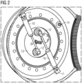
- Fig. 2 shows a device for protecting a hydraulic pitch cylinder 10 of the rotor blade 6 for the wind turbine 1 according to an embodiment.
- the device for protecting the hydraulic pitch cylinder 10 comprises a base 13 of the rotor blade 6 and the pitch cylinder 10, which comprises a first bracket 11 at one end and a second bracket 12 at another end.
- the first bracket 11 is sometimes referred as a rearend pitch cylinder bracket
- the second bracket 11 is sometimes referred as a frontend pitch cylinder bracket.
- the first bracket 11 is connected to the rotor 4 of the wind turbine 1 and the second bracket 12 is connected to the base 13 of the rotor blade 6 of the wind turbine 1.
- the second bracket 12 is connected to the base 13 of the rotor blade 6 of the wind turbine 1 at a location which is arranged radially further inwards than the mechanical stop device 14.
- the device in Fig. 2 comprises two similar pitch cylinders 10.
- Fig. 3 shows the mechanical stop device 14 according to an embodiment
- Fig. 4 shows a cross-section of the mechanical stop device 14 of Fig. 3
- the mechanical stop device 14 comprises a plate 15 having an opening 16 and a pin 17 arranged within the opening 16 with a gap between the pin 17 and the opening 16.
- the pin 17 is connected to the rotor 4
- the plate 15 is connected to the base 13 of the rotor blade 6.
- the pin 17 can be connected to the base 13 of the rotor blade 6, and the plate 15 can be connected to the rotor 4.
- the gap between the pin 17 and the opening 16 is dimensioned to determine a moving path P along which the pin 17 can be moved within the opening 16 so as to limit the maximum relative rotation between the base 13 of the rotor blade 6 and the rotor 4 of the wind turbine 1.
- the pin 17 is driven by a first actuator 21 to enter into or retract from the opening 16.
- the first actuator 21 can be embodied as hydraulic actuator or a solenoid.
- the first actuator 21 can be driven to retract the pin 17 from the opening 16, and the rotor blade 6 can be pitched, when the pin 17 is retracted from the opening 16.
- the mechanical stop device 14 can thus be activated and deactivated, i.e., flexibly be used. During ordinary pitching, a possible deformation of cylinder fittings and reinforcement plates such as the base 13 of the rotor blade 6 can be avoided.
- the mechanical stop device 14 does not move the pin 17 into the opening 16 during normal pitches to stop to avoid a system wearing by the abutting pin 17, which minimizes the risk of fretting and noise by an abutment of the pin 16 against the abutment surface 18 of the opening 16 in the plate 15.
- Fig. 5 shows a plate 15 according to an embodiment
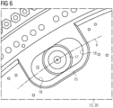
- Fig. 6 shows a plate 15 and a pin 17 according to an embodiment.
- the opening 16 comprises two abutment surfaces 18 at the left-hand side and at the right-hand side for an abutment of the pin 17.
- the opening 16 comprises a shape of an elongated slot.
- the slot can have a curved longitudinal axis.
- Fig. 7 shows another plate 15 and a pin 17 according to an embodiment
- Fig. 8 shows the other plate 15 and the pin 17 according to the embodiment of Fig. 7 at another rotational position.
- the opening 16 comprises a non-circular profile to provide a plurality of variable moving paths P for the pin 17 in accordance with a plurality of rotational positions of the plate 15, wherein each moving path P is delimited by at least one abutment surface 18 for an abutment of the pin 17.
- the plate 15 has a circular outer circumference and is rotatably received within a reinforcement member 20 of the base 13 of the rotor blade 6.
- the plate 15 can be rotatable driven by a second actuator, or it can be manually rotated and fixed at the desired rotational position.
- the plate 15 is rotated at a first rotational position to provide a first moving path P1, and in Fig. 8 , the plate 15 is rotated at a second rotational position to provide a second moving path P2.
- the first and second moving paths P1 and P2 are different from each other.
- the gap between the opening 16 and the pin 17 in Fig. 7 is different from the gap between the opening 16 and the pin 17 in Fig. 8 .
- this embodiment is preferred as the plate 15 is larger than that of Figures 5 and 6 and has many more adjustment options.
- Fig. 9 shows a base 13 of a rotor blade 6 according to an embodiment.
- the base 13 serves as a reinforcement member 20.
- the base 13 comprises a plurality of elongated holes 22.
- the elongated holes 22 are configured to receive bolts for an attachment of the second bracket 11 (frontend pitch cylinder bracket) of Fig. 2 .
- the elongated holes 22 are dimensioned and configured to enable slight shifting or adjusting the second bracket 11 of the pitch cylinder 10. By adjusting or shifting the second bracket 11 of the pitch cylinder 10, the stroke of the pitch cylinder 10 as well as tolerances can be set.
- the elongated holes 22 are preferably arrayed along a circle with equal distances between each other.
- the plate 15 can be replaceable mounted to a reinforcement member 20 of the base 13 of the rotor blade 6, wherein the reinforcement member 20 is connected to a blade bearing 19.
- a further plate (not shown) having another opening with another shape or another dimension than the opening 16 can be connected to the base 13 of the rotor blade 6 instead of the plate 15, wherein the pin 17 is also configured to be arranged within the other opening with another gap between the pin 17 and the other opening.
- the other opening 16 is dimensioned to determine another moving path P along which the pin 17 can be moved so as to limit the maximum relative rotation between the base 13 of the rotor blade 6 and the rotor 4 of the wind turbine 1 so that the stroke of the pitch cylinder 10 is kept smaller than the maximum permissible or maximum possible stroke of the pitch cylinder 10.
- the plate 15 as well as the further plate are replaceable connectable to the base 13 of the rotor blade 6.
- an appropriate plate i.e., either the plate 15 or the further plate, can be selected and connected to the base 13 of the rotor blade 6 (or at the rotor 4) to provide a desired gap between the pin 17 and the opening 16 which enables a desired moving path P of the pin 17.
- an adjustment of the stroke of the pitch cylinder 10 can be achieved, in addition or alternatively to the adjustment option provided in the embodiment having the elongated holes 22 in Fig. 9 .
- a fine adjustment of the stroke of the pitch cylinder 10 can be achieved by at least one of:
- the tolerances of the system can be controlled, and a permanent gap between the pin 17 and the opening 16 can be defined and ensures that the stroke of the pitch cylinder 10 is reduced to a known value.
Landscapes
- Engineering & Computer Science (AREA)
- Life Sciences & Earth Sciences (AREA)
- Sustainable Development (AREA)
- Sustainable Energy (AREA)
- Chemical & Material Sciences (AREA)
- Combustion & Propulsion (AREA)
- Mechanical Engineering (AREA)
- General Engineering & Computer Science (AREA)
- Physics & Mathematics (AREA)
- Fluid Mechanics (AREA)
- Wind Motors (AREA)
Abstract
Description
- The present invention relates to a device and a method of protecting a hydraulic pitch cylinder of a rotor blade for a wind turbine.
- During high winds, the wind turbine will pitch the rotor blades out of the wind, thereby decreasing the wind affected area of the rotor blade. This is done by releasing hydraulic pressure in the pitch cylinders which will extend them to their fully extended stroke/position. An extreme wind gust could in specific conditions create a pressure on the rotor blade that would tend to axially load the pitch cylinders. Previous pitch cylinder designs have been able to absorb this load in existing wind turbines, wherein the pitch cylinders are configured to withstand and receive extreme loads at the stop positions. However, an increase in rotor blade size in recent development projects creates the need to control this extension of the pitch cylinders, as wind turbines can produce loads which would exceed the capacity of the pitch cylinders.
- There may be a need for a device and a method of protecting a hydraulic pitch cylinder of a rotor blade for a wind turbine. This need may be met by the subject matters according to the independent claims. The present invention is further developed as set forth in the dependent claims.
- According to a first aspect of the invention, a device for protecting a hydraulic pitch cylinder of a rotor blade for a wind turbine is provided. The device comprises a base of the rotor blade, the pitch cylinder, which comprises a first bracket at one end and a second bracket at another end, wherein the first bracket is configured to be connected to a rotor of the wind turbine and the second bracket is connected to the base of the rotor blade of the wind turbine, and a mechanical stop device which is configured to mechanically limit a maximum relative rotation between the base of the rotor blade and the rotor of the wind turbine so that a stroke of the pitch cylinder is kept smaller than a maximum permissible or maximum possible stroke of the pitch cylinder.
- In the context of the present invention, the term "maximum permissible or maximum possible stroke of the pitch cylinder" may refer to a stroke of the pitch cylinder which can either not physically be exceeded, for example due to an internal mechanical abutment within the cylinder or due to other mechanical restrictions, or which is limited by prescribed use conditions. The above mentioned term may also refer to a stroke of the cylinder, which is intentionally reduced or set to a known limit value.
- The pitch cylinder can be designed for loads during normal operation as well as for a number of strokes during its service life. Under all extreme loads, where the deformation of the system would exceed the nominal stroke of the pitch cylinder, the load will be shared by the mechanical stop device and the pitch cylinder. The mechanical stop device can be the primary load-bearing element as it usually has a higher stiffness than the pitch cylinder.
- In an embodiment, the mechanical stop device comprises a plate having an opening and a pin arranged within the opening with a gap between the pin and the opening. The pin is connected to one of the rotor of the wind turbine and the base of the rotor blade, and the plate is connected to the other one of the rotor of the wind turbine and the base of the rotor blade. The gap is dimensioned to determine a moving path along which the pin can be moved within the opening so as to limit the maximum relative rotation between the base of the rotor blade and the rotor of the wind turbine.
- The plate absorbs excessive loads by a mechanical function, where the pin engages the opening in the plate by abutting against an abutment surface formed by the opening. The plate in turn can be mounted to a reinforcement plate that is mounted on a blade bearing, for example. Under all extreme loads, where the deformation of the system would lead to a pin movement beyond the gap, the load is shared between the mechanical stop device and the pitch cylinder.
- In an embodiment, the pin is driven by a first actuator to enter into or retract from the opening. Thereby, it is possible to retract the pin from the opening, for instance during an ordinary pitch operation of the rotor blade. The mechanical stop device can thus be activated and deactivated, i.e., flexibly be used. During ordinary pitching, a possible deformation of cylinder fittings and reinforcement plates can be avoided. The mechanical stop device does not move the pin into the opening during normal pitching to avoid a system wearing against the pin, which minimizes the risk of fretting and noise by an abutment of the pin against an abutment surface of the opening in the plate.
- By adjustments of the plate, tolerances of the system can be controlled, and a permanent gap between the pin and opening the plate can be defined and ensures that the stroke of the pitch cylinder is reliably reduced to a known value.
- In an embodiment, the opening comprises at least one abutment surface for an abutment of the pin. In an embodiment, the opening comprises a shape of an elongated slot.
- In an embodiment, the opening of the plate comprises a non-circular profile to provide a plurality of variable moving paths for the pin in accordance with a plurality of rotational positions of the plate, wherein each moving path is delimited by at least one abutment surface for an abutment of the pin. In an embodiment, the plate has a circular outer circumference and is rotatably received the base of the rotor blade, for example within a reinforcement member which is connected to the blade bearing. In an embodiment, the plate is rotatable driven by a second actuator. At higher loads, the plate according to this embodiment is preferred as it may have a larger plate with much more adjustment options.
- In an embodiment, the second bracket is connected to the base of the rotor blade of the wind turbine at a location which is arranged radially further inwards than the mechanical stop device. Thereby, the mechanical stop device serves as the primary load-bearing element, both due to the stiffness difference as mentioned above and in addition by a leverage because of the higher radius where the mechanical stop device is arranged.
- In an embodiment, the second bracket is connected to the base of the rotor blade by means of bolts passing through elongated holes which are provided in the base of the rotor blade. This enables a further adjustment option for the pitch stroke by slightly shifting or adjusting the second bracket with reference to the base of the rotor blade.
- According to a second aspect of the invention, a wind turbine comprises a rotor having a plurality of rotor blades, each rotor blade being configured to be pitched by a pitch angle about a pitch axis of the rotor blade, the rotor being mounted to a nacelle to rotate about a rotation axis with a rotor speed to drive a generator for producing electrical energy, and the nacelle being mounted to a tower to rotate about a yaw axis. The wind turbine comprises the above-described device for protecting the pitch cylinder, wherein the first bracket is connected to the rotor of the wind turbine.
- In an embodiment, the base of the rotor blade is connected to a blade bearing, and the pin is connected to the rotor of the wind turbine.
- In an embodiment, the plate is replaceable mounted the base of the rotor blade. For example, the base can be a reinforcement member which is connected to a blade bearing.
- In an embodiment, the wind turbine further comprises a further plate having another opening with another shape or another dimension than the opening, wherein the pin is also configured to be arranged within the other opening with another gap between the pin and the other opening. The pin is connected to one of the rotor and the base of the rotor blade, and the further plate is connected to the other one of the rotor and the base of the rotor blade. The other opening is dimensioned to determine another moving path along which the pin can be moved so as to limit the maximum relative rotation between the base of the rotor blade and the rotor of the wind turbine so that the stroke of the pitch cylinder is kept smaller than the maximum permissible or maximum possible stroke of the pitch cylinder. The plate as well as the further plate are replaceable connectable to the other one of the rotor and the base of the rotor blade.
- According to a third aspect of the invention, a method of protecting a hydraulic pitch cylinder of a rotor blade for a wind turbine by means of the above described device for protecting the pitch cylinder of the rotor blade for the wind turbine is provided. The device comprises a first actuator for driving the pin such that the pin is driven to enter into or retract from the opening. The method comprises steps of driving the first actuator to retract the pin from the opening, and pitching the rotor blade, when the pin is retracted from the opening.
- Thereby, the mechanical stop device can be activated and deactivated, i.e., flexibly be used. During ordinary pitching, a possible deformation of cylinder fittings and reinforcement plates can be avoided. The mechanical stop device does not move the pin into the opening during normal pitching to avoid a system wearing against the pin, which minimizes the risk of fretting and noise by an abutment of the pin against an abutment surface of the opening in the plate.
- In an embodiment, the wind turbine used in the method is embodied as described above.
- It has to be noted that embodiments of the invention have been described with reference to different subject matters. In particular, some embodiments have been described with reference to apparatus type claims whereas other embodiments have been described with reference to method type claims. However, a person skilled in the art will gather from the above and the following description that, unless other notified, in addition to any combination of features belonging to one type of subject matter also any combination between features relating to different subject matters, in particular between features of the apparatus type claims and features of the method type claims is considered as to be disclosed with this application.
- The aspects defined above and further aspects of the present invention are apparent from the examples of embodiment to be described hereinafter and are explained with reference to the examples of embodiment. The invention will be described in more detail hereinafter with reference to examples of embodiment but to which the invention is not limited.
- Fig. 1
- shows a wind turbine and the different elements thereof;
- Fig. 2
- shows a device for protecting a hydraulic pitch cylinder of a rotor blade for a wind turbine according to an embodiment.
- Fig. 3
- shows a mechanical stop device according to an embodiment.
- Fig. 4
- shows a cross-section of the mechanical stop device of
Fig. 3 . - Fig. 5
- shows a plate according to an embodiment.
- Fig. 6
- shows a plate and a pin according to an embodiment.
- Fig. 7
- shows another plate and a pin according to an embodiment.
- Fig. 8
- shows the other plate and the pin according to the embodiment of
Fig. 7 at another rotational position. - Fig. 9
- shows a base of a rotor blade according to an embodiment.
- The illustrations in the drawings are schematically. It is noted that in different figures, similar or identical elements are provided with the same reference signs.
-
Fig. 1 shows a wind turbine 1. The wind turbine 1 comprises a nacelle 3 and atower 2. The nacelle 3 is mounted at the top of thetower 2. The nacelle 3 is mounted rotatable with regard to thetower 2 by means of a yaw bearing. The axis of rotation of the nacelle 3 with regard to thetower 2 is referred to as a yaw axis 9. - The wind turbine 1 also comprises a rotor 4 with three rotor blades 6 (of which two
rotor blades 6 are depicted inFig. 1 ). Eachrotor blade 6 is configured to be pitched by a pitch angle about a pitch axis of therotor blade 6. The rotor 4 is mounted rotatable about a rotation axis 8 (rotor axis) with regard to the nacelle 3 by means of amain bearing 7. - The wind turbine 1 furthermore comprises a
generator 5. Thegenerator 5 in turn comprises a rotor connecting thegenerator 5 with the rotor 4. If the rotor 4 is connected directly to thegenerator 5, the wind turbine 1 is referred to as a gearless, direct-driven wind turbine. Such agenerator 5 is referred asdirect drive generator 5. As an alternative, the rotor 4 may also be connected to thegenerator 5 via a gear box. This type of wind turbine 1 is referred to as a geared wind turbine. The present invention is suitable for both types of wind turbines 1. - The
generator 5 is accommodated within the nacelle 3. Thegenerator 5 is arranged and prepared for converting the rotational energy from the rotor 4 into electrical energy in the shape of an AC power. -
Fig. 2 shows a device for protecting ahydraulic pitch cylinder 10 of therotor blade 6 for the wind turbine 1 according to an embodiment. The device for protecting thehydraulic pitch cylinder 10 comprises abase 13 of therotor blade 6 and thepitch cylinder 10, which comprises afirst bracket 11 at one end and asecond bracket 12 at another end. Thefirst bracket 11 is sometimes referred as a rearend pitch cylinder bracket, and thesecond bracket 11 is sometimes referred as a frontend pitch cylinder bracket. - The
first bracket 11 is connected to the rotor 4 of the wind turbine 1 and thesecond bracket 12 is connected to thebase 13 of therotor blade 6 of the wind turbine 1. Thesecond bracket 12 is connected to thebase 13 of therotor blade 6 of the wind turbine 1 at a location which is arranged radially further inwards than themechanical stop device 14. The device inFig. 2 comprises twosimilar pitch cylinders 10. - The device for protecting the
hydraulic pitch cylinder 10 further comprises amechanical stop device 14 which is configured to mechanically limit a maximum relative rotation between the base 13 of therotor blade 6 and the rotor 4 of the wind turbine 1 so that a stroke of thepitch cylinder 10 is kept smaller than a maximum permissible or maximum possible stroke of thepitch cylinder 10. -
Fig. 3 shows themechanical stop device 14 according to an embodiment, andFig. 4 shows a cross-section of themechanical stop device 14 ofFig. 3 . Themechanical stop device 14 comprises aplate 15 having anopening 16 and apin 17 arranged within theopening 16 with a gap between thepin 17 and theopening 16. In the present embodiment, thepin 17 is connected to the rotor 4, and theplate 15 is connected to thebase 13 of therotor blade 6. In a modified embodiment, thepin 17 can be connected to thebase 13 of therotor blade 6, and theplate 15 can be connected to the rotor 4. - The gap between the
pin 17 and theopening 16 is dimensioned to determine a moving path P along which thepin 17 can be moved within theopening 16 so as to limit the maximum relative rotation between the base 13 of therotor blade 6 and the rotor 4 of the wind turbine 1. - The
pin 17 is driven by afirst actuator 21 to enter into or retract from theopening 16. Thefirst actuator 21 can be embodied as hydraulic actuator or a solenoid. In operation of the wind turbine 1 and if themechanical stop device 14 is provided with thefirst actuator 21, thefirst actuator 21 can be driven to retract thepin 17 from theopening 16, and therotor blade 6 can be pitched, when thepin 17 is retracted from theopening 16. Themechanical stop device 14 can thus be activated and deactivated, i.e., flexibly be used. During ordinary pitching, a possible deformation of cylinder fittings and reinforcement plates such as thebase 13 of therotor blade 6 can be avoided. Themechanical stop device 14 does not move thepin 17 into theopening 16 during normal pitches to stop to avoid a system wearing by the abuttingpin 17, which minimizes the risk of fretting and noise by an abutment of thepin 16 against theabutment surface 18 of theopening 16 in theplate 15. -
Fig. 5 shows aplate 15 according to an embodiment, andFig. 6 shows aplate 15 and apin 17 according to an embodiment. Theopening 16 comprises twoabutment surfaces 18 at the left-hand side and at the right-hand side for an abutment of thepin 17. In this embodiment, theopening 16 comprises a shape of an elongated slot. In a modified embodiment, particularly in embodiments with long slots, the slot can have a curved longitudinal axis. -
Fig. 7 shows anotherplate 15 and apin 17 according to an embodiment, andFig. 8 shows theother plate 15 and thepin 17 according to the embodiment ofFig. 7 at another rotational position. Theopening 16 comprises a non-circular profile to provide a plurality of variable moving paths P for thepin 17 in accordance with a plurality of rotational positions of theplate 15, wherein each moving path P is delimited by at least oneabutment surface 18 for an abutment of thepin 17. Theplate 15 has a circular outer circumference and is rotatably received within a reinforcement member 20 of thebase 13 of therotor blade 6. Theplate 15 can be rotatable driven by a second actuator, or it can be manually rotated and fixed at the desired rotational position. InFig. 7 , theplate 15 is rotated at a first rotational position to provide a first moving path P1, and inFig. 8 , theplate 15 is rotated at a second rotational position to provide a second moving path P2. The first and second moving paths P1 and P2 are different from each other. Particularly the gap between the opining 16 and thepin 17 inFig. 7 is different from the gap between the opining 16 and thepin 17 inFig. 8 . At higher loads, this embodiment is preferred as theplate 15 is larger than that ofFigures 5 and6 and has many more adjustment options. -
Fig. 9 shows abase 13 of arotor blade 6 according to an embodiment. Thebase 13 serves as a reinforcement member 20. Thebase 13 comprises a plurality ofelongated holes 22. Theelongated holes 22 are configured to receive bolts for an attachment of the second bracket 11 (frontend pitch cylinder bracket) ofFig. 2 . Theelongated holes 22 are dimensioned and configured to enable slight shifting or adjusting thesecond bracket 11 of thepitch cylinder 10. By adjusting or shifting thesecond bracket 11 of thepitch cylinder 10, the stroke of thepitch cylinder 10 as well as tolerances can be set. Theelongated holes 22 are preferably arrayed along a circle with equal distances between each other. - In an embodiment, the
plate 15 can be replaceable mounted to a reinforcement member 20 of thebase 13 of therotor blade 6, wherein the reinforcement member 20 is connected to ablade bearing 19. For example, a further plate (not shown) having another opening with another shape or another dimension than theopening 16 can be connected to thebase 13 of therotor blade 6 instead of theplate 15, wherein thepin 17 is also configured to be arranged within the other opening with another gap between thepin 17 and the other opening. Theother opening 16 is dimensioned to determine another moving path P along which thepin 17 can be moved so as to limit the maximum relative rotation between the base 13 of therotor blade 6 and the rotor 4 of the wind turbine 1 so that the stroke of thepitch cylinder 10 is kept smaller than the maximum permissible or maximum possible stroke of thepitch cylinder 10. - The
plate 15 as well as the further plate are replaceable connectable to thebase 13 of therotor blade 6. Thereby, an appropriate plate, i.e., either theplate 15 or the further plate, can be selected and connected to thebase 13 of the rotor blade 6 (or at the rotor 4) to provide a desired gap between thepin 17 and theopening 16 which enables a desired moving path P of thepin 17. As a result, an adjustment of the stroke of thepitch cylinder 10 can be achieved, in addition or alternatively to the adjustment option provided in the embodiment having theelongated holes 22 inFig. 9 . - In summary, a fine adjustment of the stroke of the
pitch cylinder 10 can be achieved by at least one of: - using the
plate 15 of the embodiment inFigures 7 and8 , wherein theopening 16 comprises a non-circular profile to provide a plurality of variable moving paths P for thepin 17 in accordance with a plurality of rotational positions of theplate 15, wherein each moving path P is delimited by at least oneabutment surface 18 for an abutment of thepin 17. Theplate 15 can be manually rotated, or can be rotatable driven by the second actuator and fixed at the desired rotational position; - selecting and connecting one of at least the
replaceable plate 15 and the replaceable further plate (both can be in accordance with the embodiment ofFigures 5 and6 ) to provide a proper moving path P for thepin 17; - providing a plurality of
elongated holes 22 in thebase 13 of therotor blade 6 to enable slight shifting and adjusting of the attachment position of thesecond bracket 12. - By adjusting the
mechanical stop device 14, the tolerances of the system can be controlled, and a permanent gap between thepin 17 and theopening 16 can be defined and ensures that the stroke of thepitch cylinder 10 is reduced to a known value. - It should be noted that the term "comprising" does not exclude other elements or steps and "a" or "an" does not exclude a plurality. Also elements described in association with different embodiments may be combined. It should also be noted that reference signs in the claims should not be construed as limiting the scope of the claims.
- Independent of the grammatical term usage, individuals with male, female or other gender identities are included within the term.
Claims (15)
- A device for protecting a hydraulic pitch cylinder (10) of a rotor blade (6) for a wind turbine (1), the device comprising:a base (13) of the rotor blade (6);the pitch cylinder (10), which comprises a first bracket (11) at one end and a second bracket (12) at another end, wherein the first bracket (11) is configured to be connected to a rotor (4) of the wind turbine (1) and the second bracket (12) is connected to the base (13) of the rotor blade (6) of the wind turbine (1); anda mechanical stop device (14) which is configured to mechanically limit a maximum relative rotation between the base (13) of the rotor blade (6) and the rotor (4) of the wind turbine (1) so that a stroke of the pitch cylinder (10) is kept smaller than a maximum permissible or maximum possible stroke of the pitch cylinder (10).
- The device according to the preceding claim, whereinthe mechanical stop device (14) comprises a plate (15) having an opening (16) and a pin (17) arranged within the opening (16) with a gap between the pin (17) and the opening (16) ;wherein the pin (17) is connected to one of the rotor (4) and the base (13) of the rotor blade (6), and the plate (15) is connected to the other one of the rotor (4) and the base (13) of the rotor blade (6);wherein the gap is dimensioned to determine a moving path (P) along which the pin (17) can be moved within the opening (16) so as to limit the maximum relative rotation between the base (13) of the rotor blade (6) and the rotor (4) of the wind turbine (1).
- The device according to the preceding claim, wherein
the pin (17) is driven by a first actuator (21) to enter into or retract from the opening (16). - The device according to any one of claims 2 and 3, wherein
the opening (16) comprises at least one abutment surface (18) for an abutment of the pin (17). - The device according to any one of claims 2 to 4, wherein
the opening (16) comprises a shape of an elongated slot. - The device according to any one of claims 2 to 5, wherein
the opening (16) of the plate (15) comprises a non-circular profile to provide a plurality of variable moving paths (P) for the pin (17) in accordance with a plurality of rotational positions of the plate (15), each moving path (P) is delimited by at least one abutment surface (18) for an abutment of the pin (17). - The device according to any one of claims 2 to 6, wherein
wherein the plate (15) has a circular outer circumference and is rotatably received within the base (13) of the rotor blade (6). - The device according to any one of claims 6 and 7, wherein
the plate (15) is rotatable driven by a second actuator. - The device according to any one of claims 2 to 8, wherein
the second bracket (12) is connected to the base (13) of the rotor blade (6) of the wind turbine (1) at a location which is arranged radially further inwards than the mechanical stop device (14). - The device according to any one of claims 2 to 9, wherein
the second bracket (12) is connected to the base (13) of the rotor blade (6) by means of bolts passing through elongated holes (22) which are provided in the base (13) of the rotor blade (6). - A wind turbine (1) comprising a rotor (4) having a plurality of rotor blades (6), each rotor blade (6) being configured to be pitched by a pitch angle about a pitch axis of the rotor blade (6), the rotor (4) being mounted to a nacelle (3) to rotate about a rotation axis (8) with a rotor speed to drive a generator (5) for producing electrical energy, the nacelle (3) being mounted to a tower (2) to rotate about a yaw axis (9),
characterized by
a device for protecting the pitch cylinder (10) according to any one of the preceding claims, wherein the first bracket (11) is connected to the rotor (4) of the wind turbine (1). - The wind turbine according to the preceding claim, wherein
the base (13) of the rotor blade (6) is connected to a blade bearing (19), and the pin (17) is connected to the rotor (4) of the wind turbine (1). - The wind turbine according to any one of claims 11 and 12, wherein
the plate (15) is replaceable mounted to the base (13) of the rotor blade (6). - The wind turbine according to one of claims 11 to 13, further comprising:a further plate having another opening with another shape or another dimension than the opening (16), wherein the pin (17) is also configured to be arranged within the other opening with another gap between the pin (17) and the other opening;wherein the pin (17) is connected to one of the rotor (4) and the base (13) of the rotor blade (6), and the further plate is connected to the other one of the rotor (4) and the base (13) of the rotor blade (6);wherein the other opening (16) is dimensioned to determine another moving path along which the pin (17) can be moved so as to limit the maximum relative rotation between the base (13) of the rotor blade (6) and the rotor (4) of the wind turbine (1) so that the stroke of the pitch cylinder (10) is kept smaller than the maximum permissible or maximum possible stroke of the pitch cylinder (10);wherein the plate (15) as well as the further plate are replaceable connectable to the other one of the rotor (4) and the base (13) of the rotor blade (6).
- A method of protecting a hydraulic pitch cylinder (10) of a rotor blade (6) for a wind turbine (1) by means of the device for protecting a hydraulic pitch cylinder (10) according to any one of claims 1 to 10, wherein the device for protecting a hydraulic pitch cylinder (10) comprises a first actuator (21) for driving the pin (17) such that the pin (17) is driven to enter into or retract from the opening (16), the method comprises steps of:Driving the first actuator (21) to retract the pin (17) from the opening (16); andPitching the rotor blade (6), when the pin (17) is retracted from the opening (16).
Priority Applications (1)
| Application Number | Priority Date | Filing Date | Title |
|---|---|---|---|
| EP23195596.4A EP4520954B1 (en) | 2023-09-06 | 2023-09-06 | Device and method of protecting a hydraulic pitch cylinder of a rotor blade for a wind turbine |
Applications Claiming Priority (1)
| Application Number | Priority Date | Filing Date | Title |
|---|---|---|---|
| EP23195596.4A EP4520954B1 (en) | 2023-09-06 | 2023-09-06 | Device and method of protecting a hydraulic pitch cylinder of a rotor blade for a wind turbine |
Publications (2)
| Publication Number | Publication Date |
|---|---|
| EP4520954A1 true EP4520954A1 (en) | 2025-03-12 |
| EP4520954B1 EP4520954B1 (en) | 2026-04-01 |
Family
ID=87933887
Family Applications (1)
| Application Number | Title | Priority Date | Filing Date |
|---|---|---|---|
| EP23195596.4A Active EP4520954B1 (en) | 2023-09-06 | 2023-09-06 | Device and method of protecting a hydraulic pitch cylinder of a rotor blade for a wind turbine |
Country Status (1)
| Country | Link |
|---|---|
| EP (1) | EP4520954B1 (en) |
Citations (8)
| Publication number | Priority date | Publication date | Assignee | Title |
|---|---|---|---|---|
| EP2290228A2 (en) * | 2009-08-18 | 2011-03-02 | GE Wind Energy (Norway) AS | Blade pitch lock device |
| EP3098441A1 (en) * | 2015-05-27 | 2016-11-30 | Siemens Aktiengesellschaft | Pitch system locking arrangement |
| EP2643585B1 (en) * | 2010-11-26 | 2018-04-11 | Vestas Wind Systems A/S | A pitch system for a wind turbine |
| CN207583556U (en) * | 2017-10-30 | 2018-07-06 | 新疆金风科技股份有限公司 | The vane propeller-changing device and wind power generating set of wind power generating set |
| CN211422826U (en) * | 2020-01-20 | 2020-09-04 | 上海电气风电集团股份有限公司 | A mechanical limit structure for hydraulic pitch system of wind turbine |
| CN211975274U (en) * | 2020-03-12 | 2020-11-20 | 上海电气风电集团股份有限公司 | Hydraulic variable pitch system of wind generating set |
| WO2022268277A1 (en) * | 2021-06-23 | 2022-12-29 | Vestas Wind Systems A/S | A pitch system for a wind turbine blade |
| US20230011388A1 (en) * | 2019-12-20 | 2023-01-12 | Vestas Wind Systems A/S | Improvements relating to the transportation of wind turbine rotor hubs |
-
2023
- 2023-09-06 EP EP23195596.4A patent/EP4520954B1/en active Active
Patent Citations (8)
| Publication number | Priority date | Publication date | Assignee | Title |
|---|---|---|---|---|
| EP2290228A2 (en) * | 2009-08-18 | 2011-03-02 | GE Wind Energy (Norway) AS | Blade pitch lock device |
| EP2643585B1 (en) * | 2010-11-26 | 2018-04-11 | Vestas Wind Systems A/S | A pitch system for a wind turbine |
| EP3098441A1 (en) * | 2015-05-27 | 2016-11-30 | Siemens Aktiengesellschaft | Pitch system locking arrangement |
| CN207583556U (en) * | 2017-10-30 | 2018-07-06 | 新疆金风科技股份有限公司 | The vane propeller-changing device and wind power generating set of wind power generating set |
| US20230011388A1 (en) * | 2019-12-20 | 2023-01-12 | Vestas Wind Systems A/S | Improvements relating to the transportation of wind turbine rotor hubs |
| CN211422826U (en) * | 2020-01-20 | 2020-09-04 | 上海电气风电集团股份有限公司 | A mechanical limit structure for hydraulic pitch system of wind turbine |
| CN211975274U (en) * | 2020-03-12 | 2020-11-20 | 上海电气风电集团股份有限公司 | Hydraulic variable pitch system of wind generating set |
| WO2022268277A1 (en) * | 2021-06-23 | 2022-12-29 | Vestas Wind Systems A/S | A pitch system for a wind turbine blade |
Also Published As
| Publication number | Publication date |
|---|---|
| EP4520954B1 (en) | 2026-04-01 |
Similar Documents
| Publication | Publication Date | Title |
|---|---|---|
| US9239040B2 (en) | Root end assembly configuration for a wind turbine rotor blade and associated forming methods | |
| EP1623111B1 (en) | Wind turbine blade with lift-regulating means | |
| DE102011053712B4 (en) | WIND TURBINE ROTOR BLADE WITH ACTUABLE PROFILE PASSAGES | |
| EP2306002B1 (en) | Systems and methods for assembling a pitch control assembly for use in a wind turbine | |
| EP2643585B1 (en) | A pitch system for a wind turbine | |
| US20140010656A1 (en) | Fixation device | |
| US20110142636A1 (en) | Expansion assembly for a rotor blade of a wind turbine | |
| US9470208B2 (en) | Wind turbine and locking method | |
| EP2352918B1 (en) | Device for adjustment of a rotor blade, wind energy converter, and method for adjusting a rotor blade | |
| EP2463521A2 (en) | Pitch gear | |
| CN101978160A (en) | Active control surfaces for wind turbine blades | |
| WO2012030326A1 (en) | Gear assembly for turbine control actuators | |
| EP3653870B1 (en) | Pitch bearing arrangement | |
| EP4520954B1 (en) | Device and method of protecting a hydraulic pitch cylinder of a rotor blade for a wind turbine | |
| EP4097349B1 (en) | Wind turbine comprising variable swept area and method of controlling a wind turbine | |
| WO2003098034A1 (en) | Wind turbine rotor construction | |
| EP4248088B1 (en) | Method and system for optimizing power output of a wind turbine with yaw misalignment | |
| DE102018113760B4 (en) | Rotor bearing housing and wind turbine with rotor bearing housing | |
| US20130343889A1 (en) | Friction Wheel Drive Train for a Wind Turbine | |
| EP4438889A1 (en) | Hub assembly for a wind turbine having a spacer | |
| US12276260B1 (en) | Pitch assembly for a wind turbine having minimized micro-pitching | |
| CN223676414U (en) | Hub assemblies, wind turbines and wind turbine generators | |
| US11846266B2 (en) | Fastener assembly, wind turbine hub assembly and related methods | |
| EP4077916B1 (en) | A wind turbine with a yaw system | |
| EP4463625B1 (en) | Method and device for individually pitching blades of a wind turbine |
Legal Events
| Date | Code | Title | Description |
|---|---|---|---|
| PUAI | Public reference made under article 153(3) epc to a published international application that has entered the european phase |
Free format text: ORIGINAL CODE: 0009012 |
|
| STAA | Information on the status of an ep patent application or granted ep patent |
Free format text: STATUS: THE APPLICATION HAS BEEN PUBLISHED |
|
| AK | Designated contracting states |
Kind code of ref document: A1 Designated state(s): AL AT BE BG CH CY CZ DE DK EE ES FI FR GB GR HR HU IE IS IT LI LT LU LV MC ME MK MT NL NO PL PT RO RS SE SI SK SM TR |
|
| STAA | Information on the status of an ep patent application or granted ep patent |
Free format text: STATUS: REQUEST FOR EXAMINATION WAS MADE |
|
| 17P | Request for examination filed |
Effective date: 20250829 |
|
| GRAP | Despatch of communication of intention to grant a patent |
Free format text: ORIGINAL CODE: EPIDOSNIGR1 |
|
| STAA | Information on the status of an ep patent application or granted ep patent |
Free format text: STATUS: GRANT OF PATENT IS INTENDED |
|
| RIC1 | Information provided on ipc code assigned before grant |
Ipc: F03D 1/06 20060101AFI20251105BHEP Ipc: F03D 7/02 20060101ALI20251105BHEP |
|
| INTG | Intention to grant announced |
Effective date: 20251120 |
|
| GRAS | Grant fee paid |
Free format text: ORIGINAL CODE: EPIDOSNIGR3 |
|
| GRAA | (expected) grant |
Free format text: ORIGINAL CODE: 0009210 |
|
| STAA | Information on the status of an ep patent application or granted ep patent |
Free format text: STATUS: THE PATENT HAS BEEN GRANTED |
|
| AK | Designated contracting states |
Kind code of ref document: B1 Designated state(s): AL AT BE BG CH CY CZ DE DK EE ES FI FR GB GR HR HU IE IS IT LI LT LU LV MC ME MK MT NL NO PL PT RO RS SE SI SK SM TR |
|
| REG | Reference to a national code |
Ref country code: CH Ref legal event code: F10 Free format text: ST27 STATUS EVENT CODE: U-0-0-F10-F00 (AS PROVIDED BY THE NATIONAL OFFICE) Effective date: 20260401 Ref country code: GB Ref legal event code: FG4D |
|
| REG | Reference to a national code |
Ref country code: IE Ref legal event code: FG4D |
|
| REG | Reference to a national code |
Ref country code: DE Ref legal event code: R096 Ref document number: 602023014373 Country of ref document: DE |