EP4520951A1 - Fuel injector for gaseous fuel and valve assembly for the same - Google Patents
Fuel injector for gaseous fuel and valve assembly for the same Download PDFInfo
- Publication number
- EP4520951A1 EP4520951A1 EP24198328.7A EP24198328A EP4520951A1 EP 4520951 A1 EP4520951 A1 EP 4520951A1 EP 24198328 A EP24198328 A EP 24198328A EP 4520951 A1 EP4520951 A1 EP 4520951A1
- Authority
- EP
- European Patent Office
- Prior art keywords
- plunger
- valve seat
- control mechanism
- valve
- engaged
- Prior art date
- Legal status (The legal status is an assumption and is not a legal conclusion. Google has not performed a legal analysis and makes no representation as to the accuracy of the status listed.)
- Withdrawn
Links
Images


Classifications
-
- F—MECHANICAL ENGINEERING; LIGHTING; HEATING; WEAPONS; BLASTING
- F02—COMBUSTION ENGINES; HOT-GAS OR COMBUSTION-PRODUCT ENGINE PLANTS
- F02M—SUPPLYING COMBUSTION ENGINES IN GENERAL WITH COMBUSTIBLE MIXTURES OR CONSTITUENTS THEREOF
- F02M21/00—Apparatus for supplying engines with non-liquid fuels, e.g. gaseous fuels stored in liquid form
- F02M21/02—Apparatus for supplying engines with non-liquid fuels, e.g. gaseous fuels stored in liquid form for gaseous fuels
- F02M21/0218—Details on the gaseous fuel supply system, e.g. tanks, valves, pipes, pumps, rails, injectors or mixers
- F02M21/0248—Injectors
- F02M21/0251—Details of actuators therefor
- F02M21/0254—Electric actuators, e.g. solenoid or piezoelectric
-
- F—MECHANICAL ENGINEERING; LIGHTING; HEATING; WEAPONS; BLASTING
- F02—COMBUSTION ENGINES; HOT-GAS OR COMBUSTION-PRODUCT ENGINE PLANTS
- F02M—SUPPLYING COMBUSTION ENGINES IN GENERAL WITH COMBUSTIBLE MIXTURES OR CONSTITUENTS THEREOF
- F02M61/00—Fuel-injectors not provided for in groups F02M39/00 - F02M57/00 or F02M67/00
- F02M61/16—Details not provided for in, or of interest apart from, the apparatus of groups F02M61/02 - F02M61/14
- F02M61/20—Closing valves mechanically, e.g. arrangements of springs or weights or permanent magnets; Damping of valve lift
-
- F—MECHANICAL ENGINEERING; LIGHTING; HEATING; WEAPONS; BLASTING
- F02—COMBUSTION ENGINES; HOT-GAS OR COMBUSTION-PRODUCT ENGINE PLANTS
- F02M—SUPPLYING COMBUSTION ENGINES IN GENERAL WITH COMBUSTIBLE MIXTURES OR CONSTITUENTS THEREOF
- F02M21/00—Apparatus for supplying engines with non-liquid fuels, e.g. gaseous fuels stored in liquid form
- F02M21/02—Apparatus for supplying engines with non-liquid fuels, e.g. gaseous fuels stored in liquid form for gaseous fuels
- F02M21/0218—Details on the gaseous fuel supply system, e.g. tanks, valves, pipes, pumps, rails, injectors or mixers
- F02M21/0248—Injectors
-
- F—MECHANICAL ENGINEERING; LIGHTING; HEATING; WEAPONS; BLASTING
- F02—COMBUSTION ENGINES; HOT-GAS OR COMBUSTION-PRODUCT ENGINE PLANTS
- F02M—SUPPLYING COMBUSTION ENGINES IN GENERAL WITH COMBUSTIBLE MIXTURES OR CONSTITUENTS THEREOF
- F02M21/00—Apparatus for supplying engines with non-liquid fuels, e.g. gaseous fuels stored in liquid form
- F02M21/02—Apparatus for supplying engines with non-liquid fuels, e.g. gaseous fuels stored in liquid form for gaseous fuels
- F02M21/0218—Details on the gaseous fuel supply system, e.g. tanks, valves, pipes, pumps, rails, injectors or mixers
- F02M21/0248—Injectors
- F02M21/0257—Details of the valve closing elements, e.g. valve seats, stems or arrangement of flow passages
- F02M21/026—Lift valves, i.e. stem operated valves
- F02M21/0263—Inwardly opening single or multi nozzle valves, e.g. needle valves
-
- F—MECHANICAL ENGINEERING; LIGHTING; HEATING; WEAPONS; BLASTING
- F02—COMBUSTION ENGINES; HOT-GAS OR COMBUSTION-PRODUCT ENGINE PLANTS
- F02M—SUPPLYING COMBUSTION ENGINES IN GENERAL WITH COMBUSTIBLE MIXTURES OR CONSTITUENTS THEREOF
- F02M2200/00—Details of fuel-injection apparatus, not otherwise provided for
- F02M2200/02—Fuel-injection apparatus having means for reducing wear
-
- F—MECHANICAL ENGINEERING; LIGHTING; HEATING; WEAPONS; BLASTING
- F02—COMBUSTION ENGINES; HOT-GAS OR COMBUSTION-PRODUCT ENGINE PLANTS
- F02M—SUPPLYING COMBUSTION ENGINES IN GENERAL WITH COMBUSTIBLE MIXTURES OR CONSTITUENTS THEREOF
- F02M2200/00—Details of fuel-injection apparatus, not otherwise provided for
- F02M2200/30—Fuel-injection apparatus having mechanical parts, the movement of which is damped
- F02M2200/306—Fuel-injection apparatus having mechanical parts, the movement of which is damped using mechanical means
-
- F—MECHANICAL ENGINEERING; LIGHTING; HEATING; WEAPONS; BLASTING
- F02—COMBUSTION ENGINES; HOT-GAS OR COMBUSTION-PRODUCT ENGINE PLANTS
- F02M—SUPPLYING COMBUSTION ENGINES IN GENERAL WITH COMBUSTIBLE MIXTURES OR CONSTITUENTS THEREOF
- F02M2200/00—Details of fuel-injection apparatus, not otherwise provided for
- F02M2200/50—Arrangements of springs for valves used in fuel injectors or fuel injection pumps
-
- F—MECHANICAL ENGINEERING; LIGHTING; HEATING; WEAPONS; BLASTING
- F02—COMBUSTION ENGINES; HOT-GAS OR COMBUSTION-PRODUCT ENGINE PLANTS
- F02M—SUPPLYING COMBUSTION ENGINES IN GENERAL WITH COMBUSTIBLE MIXTURES OR CONSTITUENTS THEREOF
- F02M51/00—Fuel-injection apparatus characterised by being operated electrically
- F02M51/06—Injectors peculiar thereto with means directly operating the valve needle
- F02M51/061—Injectors peculiar thereto with means directly operating the valve needle using electromagnetic operating means
-
- Y—GENERAL TAGGING OF NEW TECHNOLOGICAL DEVELOPMENTS; GENERAL TAGGING OF CROSS-SECTIONAL TECHNOLOGIES SPANNING OVER SEVERAL SECTIONS OF THE IPC; TECHNICAL SUBJECTS COVERED BY FORMER USPC CROSS-REFERENCE ART COLLECTIONS [XRACs] AND DIGESTS
- Y02—TECHNOLOGIES OR APPLICATIONS FOR MITIGATION OR ADAPTATION AGAINST CLIMATE CHANGE
- Y02T—CLIMATE CHANGE MITIGATION TECHNOLOGIES RELATED TO TRANSPORTATION
- Y02T10/00—Road transport of goods or passengers
- Y02T10/10—Internal combustion engine [ICE] based vehicles
- Y02T10/30—Use of alternative fuels, e.g. biofuels
Definitions
- the present disclosure relates generally to a fuel injector for providing gaseous fuel for an internal combustion engine and, more particularly, to a valve assembly for a fuel injector for gaseous fuel.
- Rapid gain of injection quantity at the start of the valve opening for gaseous fuel injectors is significantly greater than the gain of injection quantity at higher injection amounts, which occur while the valve remains open.
- gaseous fuel injectors tend to have high variation between injection events and between injectors.
- rapid gain in the injection quantity at the start of injection tends to make the fuel injector less robust and more sensitive to other forces acting on the fuel injector, such as mechanical friction.
- Gaseous fuel injectors can also result in an undesirable decrease or reduction in the injected quantity of gaseous fuel for extended on times. This can be caused by rebounding of the plunger against the control surface of the fuel injector that limits the displacement of the plunger in the fuel injector. The mechanical rebounding of the plunger promotes an earlier closing of the fuel injector valve and a reduced injection quantity. Therefore, there remains a need for the unique apparatuses, systems, and techniques disclosed herein.
- the present disclosure includes a fuel injector for providing gaseous fuel to a combustion chamber.
- the fuel injector includes an injector body defining a fuel passage therein. The fuel passage extends from a gas inlet to a gas outlet of the injector body.
- the fuel injector includes a valve assembly at least partially located in the fuel passage.
- the valve assembly includes at least one valve that is selectively opened and closed to control gaseous fuel flow through the fuel passage to the combustion chamber.
- the at least one valve includes a valve seat in the fuel passage.
- the at least one valve also includes a plunger that contacts the valve seat to close the at least one valve, and the plunger is displaced from the valve seat to open the at least one valve.
- First and second plunger control mechanisms resist displacement of the plunger away from the valve seat. The first and second plunger control mechanisms are configured to increase resistance to displacement of the plunger from the valve seat during opening of the at least one valve.
- a valve assembly for a fuel injector to selectively provide gaseous fuel flow.
- the valve assembly includes a valve seat including an opening to allow gaseous fuel flow through the opening.
- the valve assembly also includes a plunger that is movable to engage the valve seat to prevent gaseous fuel flow through opening and to disengage the valve seat to permit gaseous fuel flow through the valve seat.
- the valve assembly also includes a first plunger control mechanism engaged to the plunger.
- the first plunger control mechanism is configured to resist displacement of the plunger away from the valve seat during opening of the valve assembly, and to bias the plunger against the valve seat to close the valve assembly.
- the valve assembly further includes a second plunger control mechanism spaced from the plunger when the plunger is engaged to the valve seat. The second plunger control mechanism engages the plunger after the plunger is displaced away from the valve seat to work with the first plunger control mechanism to resist displacement of the plunger away from the valve seat during opening of the valve assembly.
- a fuel injection system 10 including at least one fuel injector 100a, 100b, 100c ... 100n for a respective combustion chamber 14 of an internal combustion engine 12.
- the at least one fuel injector 100a, 100b, 100c ... 100n is in fluid communication with a fuel source 16 containing a gaseous fuel 18, and a fuel tank/regulator 20 and/or common rail 22 to distribute fuel to the injectors 100a, 100b, 100c ... 100n.
- system 10 may include any number of fuel injectors, including one fuel injector.
- Pressurized gaseous fuel 18 is supplied to each of the fuel injectors 100a, 100b, 100c ... 100n from the fuel tank/regulator 20.
- fuel injectors 100a, 100b, 100c ... 100n are described with reference to a fuel injector 100, such as shown in FIGs. 2-10 .
- the fuel injector 100 provides gaseous fuel 18 to combustion chamber 14.
- the fuel injector 100 includes an injector body 101 defining a fuel passage 102 therein.
- the fuel passage 102 extends from a gas inlet 104 to a gas outlet 106 of the body 101.
- the fuel injector 100 includes a valve assembly 160 at least partially located in the fuel passage 102.
- the valve assembly 160 includes at least one valve 162 that is selectively opened and closed to control gaseous fuel flow through the fuel passage 102 to the combustion chamber 14.
- the at least one valve 162 includes a valve seat 168 in the fuel passage 102.
- the at least one valve 162 also includes a plunger 164 that contacts the valve seat 168 to close the at least one valve 162, and the plunger 164 is displaced from the valve seat 168 to open the at least one valve 162.
- the valve 162 includes a first plunger control mechanism 120 and a second plunger control mechanism 130.
- First and second plunger control mechanisms 120, 130 resist displacement of the plunger 164 away from the valve seat 168.
- the first and second plunger control mechanisms 120, 130 are configured to increase resistance to displacement of the plunger 164 from the valve seat 168 during opeing of the at least one valve 162 based on a distance of the plunger 164 from the valve seat 168.
- valve assembly 160 is disclosed for fuel injector 100 to selectively provide gaseous fuel flow.
- the valve assembly 160 includes valve seat 168 including an opening 210 to allow gaseous fuel flow through the opening 210.
- the valve assembly 160 also includes plunger 164 that is movable to engage the valve seat 168 to prevent gaseous fuel flow through opening 210 and to disengage the valve seat 168 to permit gaseous fuel flow through the valve seat 164.
- the valve assembly 160 also includes first plunger control mechanism 120 engaged to the plunger 164.
- the first plunger control mechanism 120 is configured to resist displacement of the plunger 164 away from the valve seat 168 during opening of the valve assembly 160, and to bias the plunger 164 against the valve seat 168 to close the valve assembly 160.
- the valve assembly 160 also includes second plunger control mechanism 130 configured to not resist movement of the plunger 164 from engagement with the valve seat 168.
- the second plunger control mechanism 130 resists the plunger 164 after the plunger 164 is displaced away from the valve seat 168 to work with the first plunger control mechanism 120 to resist displacement of the plunger 164 away from the valve seat 168 during opening of the valve assembly 160.
- an exemplary injector body 101 for an embodiment of fuel injector 100 extends along a longitudinal axis A and includes fuel passage 102 that is defined by the injector body 101.
- Fuel passage 102 provides a gaseous fuel flow path from gas inlet 104 to gas outlet 106.
- gas inlet 104 is a sidewall inlet of injector body 101 that is transverse to longitudinal axis A.
- Gas outlet is located a distal end of injector body 101 and is located on, or extends along, longitudinal axis A.
- proximal or “proximally” refer to an axial location or upstream direction away from gas outlet 106
- distal or disally refers to an axial location or downstream direction toward gas outlet 106.
- valve assembly 160 receives valve assembly 160 therein to control gaseous fuel flow from gas inlet 104 to gas outlet 106.
- Valve assembly 160 may also control combustion gas flow from gas outlet 106 into fuel passage 102.
- Valve assembly 160 may include one or more valves to control gaseous fuel flow from and/or into fuel passage 102.
- valve assembly 160 may include a second valve spaced longitudinally from valve 162.
- valve assembly 160 includes valve 162 having a plunger 164 and a valve seat 168.
- An end face of plunger 164 includes a seal 180 (see FIG. 7 , for example) that sealing engages valve seat 168 when injector 100 is in the closed position, as shown in FIGs. 2 and 4 .
- Gas outlet 106 is opened by axially displacing plunger 164 away from valve seat 168, as shown in FIGs. 3 and 5 .
- valve seat 168 is a radially positioned seat that is sealed by one or more seals that extends around that outer sidewall of plunger 164.
- plunger 164 moves proximally away from valve seat 168 to open valve 162. In other embodiments, plunger 164 moves distally away from valve seat 168 to open valve 162. In still other embodiments, valve seat 168 may be displaced from plunger 164 to open valve 162.
- Fuel injector 100 further includes one or more plunger control mechanisms 120, 130 that resist axial displacement of plunger 164 to open gas outlet 106 and/or bias plunger 164 into sealing engagement with valve seat 168 to close gas outlet 106.
- the plunger control mechanisms 120, 130 may act directly on plunger 164, and/or may act on one or more components connected to or that move with movement of plunger 164, such as an armature, washer, spacer, spring, etc.
- first plunger control mechanism 120 is coupled between injector body 101 and plunger 164.
- First plunger control mechanism 120 includes a first end 122 that may be engaged directly to plunger 164 or engaged to one or more components engaged to plunger 164, such as an armature.
- First plunger control mechanism 120 includes an opposite second end 124 that may be engaged directly to injector body 101 or to one or more components engaged to injector body 101.
- First plunger control mechanism 120 includes at least one biasing element that is configured to provide a variable force resistance to displacement of plunger 164.
- First plunger control mechanism 120 is active at all lift or displacement positions of plunger 164 relative to valve seat 168. The force of resistance provided by first plunger control mechanism 120 can increase as plunger 164 is displaced further from valve seat 168.
- Fuel injector 100 also includes a second plunger control mechanism 130 that is engaged to injector body 101.
- Second plunger control mechanism 130 includes a first end 132 that is spaced from plunger 164 by a gap 126 when plunger 164 is positioned in engagement with valve seat 168.
- the first end 132 of second plunger control mechanism 122 includes a second plunger 136 that is supported directly or indirectly by injector body 101.
- Second plunger control mechanism 122 includes an opposite second end 134 that may be engaged directly to injector body 101 or to one or more components engaged to injector body 101.
- Second plunger control mechanism 130 includes at least one biasing element that is configured to provide a second variable force resistance to displacement of plunger 164 once gap 126 is eliminated that supplements or adds to the resistance provided by first plunger control mechanism 120. Second plunger control mechanism 122 is therefore only active while plunger 164 is spaced from valve seat 168 by a distance that is at least as great as gap 126.
- First plunger control mechanism 120 can include, for example, one or more biasing elements that resist displacement of plunger 164 and bias plunger 164 toward valve seat 168.
- the one or more biasing elements may include, for example, springs, coil springs, wave springs, plungers, dampeners, shims, disks, washers, Belleville washers spacers, and/or other devices that resist, work separately, or work together to control displacement of plunger 164 away from valve seat 168 in response to a fuel injection command.
- Second plunger control mechanism 130 can include, for example include, for example, one or more biasing elements that resist displacement of plunger 164 and bias plunger 164 toward valve seat 168 after plunger 164 is displaced from valve seat 168.
- the one or more biasing elements can include, for example, springs, coil springs, wave springs, plungers, dampeners, shims, disks, washers, Belleville washers spacers, and/or other devices that resist, work separately, or work together to control displacement of plunger 164 away from valve seat 168 after plunger 164 has been initially separated from valve seat 168 in response to a fuel injection command.
- Fuel injector 100 includes injector body 101.
- Injector body 101 can be comprised of multiple parts that are coupled to one another to form injector body 101.
- injector body 101 includes a valve assembly receiving part 140 extending from gas outlet end 106 at a distal end thereof to a proximal end 142, and an actuator mounting part 144 that receives proximal end 142 and is coupled to valve assembly receiving part 140.
- Other embodiments contemplate an injector body 101 made from a single body part, or from more than two body parts.
- Actuator mounting part 144 includes a flanged end 146 to facilitate mounting of the actuator 190 on fuel injector 100.
- a feature may also be provided on the injector body 101 to facilitate injector mounting on engine 12.
- actuator 190 includes an actuation part 192 secured to flanged end 146 with a cap assembly 194.
- Cap assembly 194 includes a retainer 196 positioned in and engaged to mounting part 144, and a cap 198 engaged to retainer 196 to secure actuation part 192 between cap 198 and flanged end 146.
- Actuator 190 also includes an actuated part 200 in actuator mounting part 144 that is engaged to plunger 164.
- Actuator 190 controls the opening of the gaseous fuel flow valve assembly 160, including the valve 162.
- actuator 190 is an electronic actuator, such as a solenoid, that is electronically controlled by energizing and de-energizing a magnetic coil to actively and selectively control opening and closing for valve 162 of valve assembly 160.
- the actuation part 192 is a solenoid
- retainer 196 is a stator
- the actuated part 200 is an armature coupled to plunger 164.
- the actuated part 200 is axially displaced in injector body 101 by actuation part 192 to axially displace plunger 164 away from seat 168 in response to a fuel injection command.
- plunger 162 includes an axially extending stem 170 that extends from valve assembly receiving part 140 into actuator mounting part 144.
- Plunger 162 includes a plunger body 172 at a distal end of stem 170.
- Stem 170 is coupled to the actuated part 200 of actuator 190, such as an armature.
- Body 172 includes an interior chamber 174 and a plurality of sidewall openings 176 that admit gaseous fuel flow into chamber 174.
- the distal end of body 172 includes an end face 178 with a seal 180 ( FIG. 7 ), and a central opening 182 around which seal 180 extends.
- Sidewall openings 176 are in fluid communication with one or more sidewall inlets 148 of valve assembly receiving part 140 to receive gaseous fuel 18 from fuel system 10.
- Valve seat 168 is mounted at a distal end of valve assembly receiving part 140.
- Valve seat 168 includes a seat body 208 with an annular opening 210 that receives gaseous fuel flow when plunger 164 is axially displaced away from valve seat 168.
- seat body 208 includes first and second annular projections 212, 214 that are sealing engaged by seal 180 when plunger 164 is in the closed position.
- Valve seat 168 also includes a flow path 216 from opening 210 to gas outlet 106.
- First plunger control mechanism 120 includes a first biasing element 220, such as a coil spring as illustrated in FIG. 6 .
- Biasing element 220 is engaged to actuated part 200, such as an armature and/or plunger 164, and to a spring guide 222 within retainer 196. Biasing element 220 biases plunger 164 distally so that seal 180 sealingly engages against projections 212, 214 of valve seat 168.
- a second biasing element 230 is spaced from a flange 184 of plunger 164.
- Biasing element 230 may be, for example, a washer, plate, disk, a Belleville washer, spring, or other device used in combination with coil spring 220 to provide the desired variable axial forces to resist displacement of plunger 164.
- dampening elements such as viscoelastic dampening elements, may be employed that act in parallel with coil spring 220 and/or biasing element 230.
- a shim or spacer 232 is provided between a distally facing surface 150 of receiving part 140 and biasing element 230. Shim 232 sets the gap 126 in which biasing element 230 is spaced from plunger 164 in the closed position of plunger 164.
- flange 184 of plunger 164 contacts biasing element 230 to provide additional resistance to axial displacement of plunger 164.
- Biasing element 230 also resists or prevents plunger flange 184 from impacting against or rebounding from surface 150 of valve assembly receiving part 140.
- second plunger control mechanism 130 includes a second biasing element 240, a first shim 242 that spaces biasing element 240 from distally facing surface 150, a second shim 244 that sets a distance biasing element 240 is able to be compressed relative to its free length, and a third shim 246.
- biasing element 240 is a wave spring.
- biasing element 240 is a single turn, overlap wave spring.
- first shim 242 sets the minimum air gap between an armature (for example, actuated part 200) and a stator (for example, retainer 196) of actuator 190.
- third shim 246 sets the distance plunger 164 is lifted before contacting second biasing element 240, the establishing the gap 126 such as shown in FIG. 2 .
- second shim 244 extends axially from first shim 242 along an inner side of biasing element 240. In other embodiments, second shim 244 is located around the outer side of biasing element 240.
- FIG. 9 Another embodiment of second plunger control mechanism 130 is shown in FIG. 9 .
- This embodiment includes a second plunger 136 as part of the second plunger control mechanism 130.
- second plunger control mechanism 130 includes a second biasing element 250, and a second plunger 252 in contact with second biasing element 250.
- Second plunger 252 is a plate in the form of a disc-shaped element with a recessed surface part 266 that receives biasing element 250.
- Second plunger control mechanism 130 also includes a first shim 254 in contact with second plunger 252.
- First shim 254 axially spaces second plunger 252 from a second, distal flange 186 of plunger 164 that is located at or adjacent first end 178 of plunger 164.
- First shim 254 has a height selected to axially space second plunger 252 from second flange 186 of plunger 164 to establish gap 126.
- a shim biasing element 256 extends around second plunger 252 and holds first shim 254 in an axial position in valve assembly receiving part 140 of injector body 101.
- second biasing element 250 and shim biasing element 256 are coil springs.
- Valve assembly receiving part 140 further includes a plunger guide 258 located in valve assembly receiving part 140.
- Plunger guide 258 includes a radial portion 260 extending along distally facing surface 150, and an axial portion 262 extending along passage 264 to guide stem 170. Second biasing element 250 and shim biasing element 256 contact radial portion 260 of plunger guide 258.
- plunger guide 258 is made from hardened, wear resistant metal material.
- first plunger 164 is axially displaced from valve seat 164, and displacement is resisted by biasing element 220 alone.
- Second biasing element 250 works in conjunction with first biasing element 220 to resist axial displacement of plunger 264 away from valve seat 268.
- FIG. 10 illustrates another embodiment of fuel injector 100 that includes a second plunger control mechanism 130 with a second plunger 136.
- second plunger control mechanism 130 includes a second biasing element 270, and a second plunger 272 in contact with second biasing element 270.
- Second plunger 272 is an elongated member with a proximal cap 274 that receives and guides biasing element 270, a stem 276 that extends to a distal end 278, and a flange 282 between stem 276 and cap 274.
- Distal end 278 is spaced proximally from a proximal end of plunger 164 by gap 126.
- Second plunger control mechanism 130 also includes a first shim 280 between flange 282 and an internal lip 197 of retainer 196 that establishes gap 126.
- Second plunger 272 can be movably supported in an axially fixed upper plunger guide 284.
- Biasing element 220 of first plunger control mechanism 120 can be positioned between actuated member 220 and plunger guide 284 to bias plunger 164 into contact with seat 168.
- An optional shim 286 can be provided between valve assembly receiving part 140 actuator mounting part 144 to adjust the minimum axial air gap between actuation part 192 and actuated part 200 of actuator 190.
- first plunger 164 is axially displaced from valve seat 164, and displacement is resisted by biasing element 220 alone.
- Second biasing element 270 works in conjunction with first biasing element 220 to resist axial displacement of plunger 264 away from valve seat 268.
- the first and second plunger control mechanisms 120, 130 are configured to increase resistance to displacement of the plunger 164 away from the valve seat 168 during opening of the at least one valve 162.
- the first and second plunger control mechanisms 120, 130 are configured to so that second plunger control mechanism 130 incrementally or sequentially engages plunger 164 only when plunger 164 is spaced from seat 168 more than a threshold distance, such as gap 126, while first plunger control mechanism 120 is always actively engaged to plunger 164.
- first and second plunger control mechanisms 120, 130 are configured to so that second plunger control mechanism 130 supplements resistance to displacement of plunger 164 that is provided by first plunger control mechanism 120 only when plunger 164 is spaced from seat 168 more than a threshold distance, such as gap 126.
- first and second plunger control mechanisms 120, 130 are configured to so that second plunger control mechanism 130 actively engages plunger 164 only when plunger 164 is spaced from seat 168 more than the threshold distance, such as gap 126, while first plunger control mechanism 120 is always actively engaged to plunger 164.
- the first plunger control mechanism 120 is located in the injector body 101 proximally of the second plunger control mechanism 130. In an embodiment, the first plunger control mechanism 120 is located in the injector body 101 distally of the second plunger control mechanism 130.
- a fuel injector for providing gaseous fuel to a combustion chamber.
- the fuel injector includes an injector body defining a fuel passage therein.
- the fuel passage extends from a gas inlet to a gas outlet of the injector body.
- the fuel injector includes a valve assembly in the fuel passage.
- the valve assembly includes at least one valve that is selectively opened and closed to control gaseous fuel flow through the fuel passage to the combustion chamber.
- the at least one valve includes a valve seat in the fuel passage.
- the at least one valve also includes a plunger that contacts the valve seat to close the at least one valve, and the plunger is displaced from the valve seat to open the at least one valve.
- First and second plunger control mechanisms resist displacement of the plunger away from the valve seat.
- the first and second plunger control mechanisms are configured to increase resistance to displacement of the plunger from the valve seat during opening of the at least one valve based on a distance of the plunger from the valve seat.
- the plunger includes an end face that contacts the valve seat with the at least one valve in the closed position. Only the first plunger control mechanism biases the plunger into contact with the valve seat.
- a gap is formed between the second plunger control mechanism and the plunger with the at least one valve in the closed position.
- the first plunger control mechanism is always coupled to the plunger to bias the plunger toward the closed position against the valve seat and resist displacement of the plunger from the valve seat during opening of the at least one valve.
- the second plunger control mechanism includes a second plunger spaced from the plunger with the at least one valve in the closed position, and a biasing element that resists displacement of the second plunger when the plunger is displaced from the valve seat a sufficient distance to contact the second plunger during opening of the at least one valve.
- an actuator is actuatable to axially displace the plunger to open the at least one valve.
- the plunger includes a first end and an opposite second end, and the plunger includes a flange adjacent the first end and an elongated stem extending to the second end.
- the elongated stem of the plunger is engaged to the actuator, and the first plunger control mechanism is engaged between the actuator and the injector body.
- the second plunger control mechanism includes a second plunger axially spaced from the second end of the plunger when the plunger is in contact with the valve seat. The second end of the plunger contacts the second plunger after displacement of the first end of the plunger away from the valve seat.
- the second plunger control mechanism also includes a biasing element that resists displacement of the second plunger by the plunger as the plunger moves away from the valve seat.
- the second plunger control mechanism includes a plate positioned in the fuel passage and a biasing element between the plate and the injector body.
- the plate is axially spaced from the flange of the plunger when the plunger is in contact with the valve seat.
- the flange of the plunger contacts the plate after displacement of the first end of the plunger away from the valve seat, and the biasing element resists displacement of the plate by the plunger as the plunger moves away from the valve seat.
- the second plunger control mechanism is spaced from the flange of the plunger when the plunger is in contact with the valve seat.
- the first plunger control mechanism resists displacement of the plunger in response to actuation of the actuator to displace the first end of the plunger from the valve seat.
- the flange contacts the second plunger control mechanism after displacement of the first end of the plunger from the valve seat.
- the actuator includes an armature
- the stem of the plunger is engaged to the armature
- the first plunger control mechanism includes a biasing element engaged to the armature to bias the plunger into contact with the valve seat.
- the second plunger control mechanism is located in the fuel passage and is engaged to the injector body.
- the second plunger control mechanism includes at least one of a disc, a Belleville washer, a wave spring, and a coil spring.
- a valve assembly for a fuel injector to selectively provide gaseous fuel flow.
- the valve assembly includes a valve seat including an opening to allow gaseous fuel flow through the valve seat.
- the valve assembly also includes a plunger that is movable to engage the valve seat to prevent gaseous fuel flow through opening and to disengage the valve seat to permit gaseous fuel flow through the valve seat.
- the valve assembly also includes a first plunger control mechanism engaged to the plunger.
- the first plunger control mechanism is configured to resist displacement of the plunger away from the valve seat during opening of the valve assembly, and to bias the plunger against the valve seat to close the valve assembly.
- the valve assembly also includes a second plunger control mechanism configured to not resist movement of the plunger from engagement with the valve seat. The second plunger control mechanism engages the plunger after the plunger is displaced away from the valve seat to work with the first plunger control mechanism to resist displacement of the plunger away from the valve seat during opening of the valve assembly.
- the opening of the valve seat is formed by an annular passage between first and second annular projections, and the plunger extends between a first end and an opposite second end.
- the second end includes an end face, and the end face has an annular seal that sealingly engages the first and second annular projections to close the opening when the plunger is engaged to the valve seat.
- the first plunger control mechanism is a spring that is always engaged to the plunger.
- the second plunger control mechanism includes at least one of a disc, a Belleville washer, a wave spring, and a coil spring that is spaced from the plunger when the plunger is engaged to the valve seat and that engages the plunger only after the plunger is displaced away from the valve seat.
- the plunger includes a stem and a plunger body at a distal end of the stem.
- the first plunger control mechanism is engaged to the stem, and the second plunger control mechanism engages the plunger body to resist displacement of the plunger only after the plunger is displaced away from the valve seat.
- a shim supports the second plunger control mechanism in the spaced relationship from the plunger when the plunger is engaged to the valve seat.
- the second plunger control mechanism includes a second plunger that is spaced from the plunger when the plunger is engaged to the valve seat, and a biasing element engaged to the second plunger.
- the biasing element resists displacement of the second plunger and the plunger in response to the plunger being displaced from the valve seat into contact with the second plunger.
- the second plunger control mechanism includes a plate that is spaced from the plunger when the plunger is engaged to the valve seat, and a biasing element engaged to the plate.
- the biasing element resists displacement of the plate and the plunger in response to the plunger being displaced from the valve seat into contact with the plate.
Landscapes
- Engineering & Computer Science (AREA)
- Chemical & Material Sciences (AREA)
- Combustion & Propulsion (AREA)
- Mechanical Engineering (AREA)
- General Engineering & Computer Science (AREA)
- Chemical Kinetics & Catalysis (AREA)
- General Chemical & Material Sciences (AREA)
- Oil, Petroleum & Natural Gas (AREA)
- Analytical Chemistry (AREA)
- Fuel-Injection Apparatus (AREA)
Abstract
A fuel injector for gaseous fuel is provided. The fuel injector includes at least one valve having a valve seat and a plunger that engages the seat to prevent gaseous fuel flow and is displaced from the seat to permit gaseous fuel flow. Displacement of the plunger away from the seat to open the at least one valve is resisted by a first plunger control mechanism and then a second plunger control mechanism depending on the distance the plunger is lifted from the seat.
Description
- The present application claims priority to, and the benefit of the filing date of,
U.S. Provisional Application Ser. No. 63/580,777 filed on September 6, 2023 - The present disclosure relates generally to a fuel injector for providing gaseous fuel for an internal combustion engine and, more particularly, to a valve assembly for a fuel injector for gaseous fuel.
- It is desirable for fuel injectors for gaseous fuel operated engines to be able to inject gaseous fuel into the combustion chambers of the engine at precisely controlled quantities, rates, and timing. At the start of injection for gaseous fuel injectors, there is a rapid gain or increase in the injected quantity of gaseous fuel. This results from the ballistics of the axial travel of the plunger during opening of the fuel injector valve, and the delay in closing the valve following the end of the commanded on time of the fuel injector.
- Rapid gain of injection quantity at the start of the valve opening for gaseous fuel injectors is significantly greater than the gain of injection quantity at higher injection amounts, which occur while the valve remains open. As a result, gaseous fuel injectors tend to have high variation between injection events and between injectors. In addition, the rapid gain in the injection quantity at the start of injection tends to make the fuel injector less robust and more sensitive to other forces acting on the fuel injector, such as mechanical friction.
- Gaseous fuel injectors can also result in an undesirable decrease or reduction in the injected quantity of gaseous fuel for extended on times. This can be caused by rebounding of the plunger against the control surface of the fuel injector that limits the displacement of the plunger in the fuel injector. The mechanical rebounding of the plunger promotes an earlier closing of the fuel injector valve and a reduced injection quantity. Therefore, there remains a need for the unique apparatuses, systems, and techniques disclosed herein.
- For the purposes of clearly, concisely and exactly describing illustrative embodiments of the present disclosure, the manner, and process of making and using the same, and to enable the practice, making and use of the same, reference will now be made to certain exemplary embodiments, including those illustrated in the figures, and specific language will be used to describe the same. It shall nevertheless be understood that no limitation of the scope of the invention is thereby created and that the invention includes and protects such alterations, modifications, and further applications of the exemplary embodiments as would occur to one skilled in the art.
- The present disclosure includes a fuel injector for providing gaseous fuel to a combustion chamber. The fuel injector includes an injector body defining a fuel passage therein. The fuel passage extends from a gas inlet to a gas outlet of the injector body. The fuel injector includes a valve assembly at least partially located in the fuel passage. The valve assembly includes at least one valve that is selectively opened and closed to control gaseous fuel flow through the fuel passage to the combustion chamber. The at least one valve includes a valve seat in the fuel passage. The at least one valve also includes a plunger that contacts the valve seat to close the at least one valve, and the plunger is displaced from the valve seat to open the at least one valve. First and second plunger control mechanisms resist displacement of the plunger away from the valve seat. The first and second plunger control mechanisms are configured to increase resistance to displacement of the plunger from the valve seat during opening of the at least one valve.
- In an embodiment, a valve assembly is disclosed for a fuel injector to selectively provide gaseous fuel flow. The valve assembly includes a valve seat including an opening to allow gaseous fuel flow through the opening. The valve assembly also includes a plunger that is movable to engage the valve seat to prevent gaseous fuel flow through opening and to disengage the valve seat to permit gaseous fuel flow through the valve seat. The valve assembly also includes a first plunger control mechanism engaged to the plunger. The first plunger control mechanism is configured to resist displacement of the plunger away from the valve seat during opening of the valve assembly, and to bias the plunger against the valve seat to close the valve assembly. The valve assembly further includes a second plunger control mechanism spaced from the plunger when the plunger is engaged to the valve seat. The second plunger control mechanism engages the plunger after the plunger is displaced away from the valve seat to work with the first plunger control mechanism to resist displacement of the plunger away from the valve seat during opening of the valve assembly.
- This summary is not intended to identify key or essential features of the claimed subject matter, nor is it intended to be used as an aid in limiting the scope of the claimed subject matter. Further embodiments, forms, objects, features, advantages, aspects, and benefits shall become apparent from the following description and drawings.
- The description herein makes reference to the accompanying drawings wherein like numerals refer to like parts throughout the several views, and wherein:
-
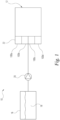
FIG. 1 is a schematic view of a fuel injection system. -
FIG. 2 is schematic section view of a fuel injector in a closed condition according to an embodiment of the present disclosure. -
FIG. 3 is the fuel injector ofFIG. 2 in an open condition. -
FIG. 4 is schematic section view of a fuel injector in a closed condition according to another embodiment of the present disclosure. -
FIG. 5 is the fuel injector ofFIG. 4 in an open condition. -
FIG. 6 is a longitudinal section view of a fuel injector according an embodiment of the present disclosure. -
FIG. 7 is a longitudinal section view of a valve assembly that can be implemented in the fuel injector ofFIG. 6 according to an embodiment of the present disclosure. -
FIG. 8 is a longitudinal section view of a valve assembly that can be implemented in the fuel injector ofFIG. 6 according to another embodiment of the present disclosure. -
FIG. 9 is a longitudinal section view of a valve assembly that can be implemented in the fuel injector ofFIG. 6 according to another embodiment of the present disclosure. -
FIG. 10 is a longitudinal section view of a fuel injector with a valve assembly according another embodiment of the present disclosure. - With reference to
FIG. 1 , there is illustrated afuel injection system 10 including at least onefuel injector internal combustion engine 12. The at least onefuel injector fuel source 16 containing agaseous fuel 18, and a fuel tank/regulator 20 and/orcommon rail 22 to distribute fuel to theinjectors FIG. 1 ,system 10 may include any number of fuel injectors, including one fuel injector. Pressurizedgaseous fuel 18 is supplied to each of thefuel injectors regulator 20. In the discussion that follows,fuel injectors fuel injector 100, such as shown inFIGs. 2-10 . - In an embodiment, the
fuel injector 100 providesgaseous fuel 18 to combustion chamber 14. Thefuel injector 100 includes aninjector body 101 defining afuel passage 102 therein. Thefuel passage 102 extends from agas inlet 104 to agas outlet 106 of thebody 101. Thefuel injector 100 includes avalve assembly 160 at least partially located in thefuel passage 102. Thevalve assembly 160 includes at least onevalve 162 that is selectively opened and closed to control gaseous fuel flow through thefuel passage 102 to the combustion chamber 14. - The at least one
valve 162 includes avalve seat 168 in thefuel passage 102. The at least onevalve 162 also includes aplunger 164 that contacts thevalve seat 168 to close the at least onevalve 162, and theplunger 164 is displaced from thevalve seat 168 to open the at least onevalve 162. Thevalve 162 includes a firstplunger control mechanism 120 and a secondplunger control mechanism 130. First and secondplunger control mechanisms plunger 164 away from thevalve seat 168. The first and secondplunger control mechanisms plunger 164 from thevalve seat 168 during opeing of the at least onevalve 162 based on a distance of theplunger 164 from thevalve seat 168. - In an embodiment,
valve assembly 160 is disclosed forfuel injector 100 to selectively provide gaseous fuel flow. Thevalve assembly 160 includesvalve seat 168 including anopening 210 to allow gaseous fuel flow through theopening 210. Thevalve assembly 160 also includesplunger 164 that is movable to engage thevalve seat 168 to prevent gaseous fuel flow throughopening 210 and to disengage thevalve seat 168 to permit gaseous fuel flow through thevalve seat 164. Thevalve assembly 160 also includes firstplunger control mechanism 120 engaged to theplunger 164. The firstplunger control mechanism 120 is configured to resist displacement of theplunger 164 away from thevalve seat 168 during opening of thevalve assembly 160, and to bias theplunger 164 against thevalve seat 168 to close thevalve assembly 160. Thevalve assembly 160 also includes secondplunger control mechanism 130 configured to not resist movement of theplunger 164 from engagement with thevalve seat 168. The secondplunger control mechanism 130 resists theplunger 164 after theplunger 164 is displaced away from thevalve seat 168 to work with the firstplunger control mechanism 120 to resist displacement of theplunger 164 away from thevalve seat 168 during opening of thevalve assembly 160. - Referring to
FIGs. 2-5 , anexemplary injector body 101 for an embodiment offuel injector 100 extends along a longitudinal axis A and includesfuel passage 102 that is defined by theinjector body 101.Fuel passage 102 provides a gaseous fuel flow path fromgas inlet 104 togas outlet 106. In the illustrated embodiment,gas inlet 104 is a sidewall inlet ofinjector body 101 that is transverse to longitudinal axis A. Gas outlet is located a distal end ofinjector body 101 and is located on, or extends along, longitudinal axis A. In the present disclosure, "proximal" or "proximally" refer to an axial location or upstream direction away fromgas outlet 106, and "distal" or "distally" refers to an axial location or downstream direction towardgas outlet 106. - The
fuel passage 102 receivesvalve assembly 160 therein to control gaseous fuel flow fromgas inlet 104 togas outlet 106.Valve assembly 160 may also control combustion gas flow fromgas outlet 106 intofuel passage 102.Valve assembly 160 may include one or more valves to control gaseous fuel flow from and/or intofuel passage 102. For example,valve assembly 160 may include a second valve spaced longitudinally fromvalve 162. - In the illustrated embodiment,
valve assembly 160 includesvalve 162 having aplunger 164 and avalve seat 168. An end face ofplunger 164 includes a seal 180 (seeFIG. 7 , for example) that sealing engagesvalve seat 168 wheninjector 100 is in the closed position, as shown inFIGs. 2 and 4 .Gas outlet 106 is opened by axially displacingplunger 164 away fromvalve seat 168, as shown inFIGs. 3 and 5 . Other embodiments contemplate thatvalve seat 168 is a radially positioned seat that is sealed by one or more seals that extends around that outer sidewall ofplunger 164. - In the illustrated embodiments,
plunger 164 moves proximally away fromvalve seat 168 to openvalve 162. In other embodiments,plunger 164 moves distally away fromvalve seat 168 to openvalve 162. In still other embodiments,valve seat 168 may be displaced fromplunger 164 to openvalve 162. -
Fuel injector 100 further includes one or moreplunger control mechanisms plunger 164 to opengas outlet 106 and/orbias plunger 164 into sealing engagement withvalve seat 168 to closegas outlet 106. As used herein, theplunger control mechanisms plunger 164, and/or may act on one or more components connected to or that move with movement ofplunger 164, such as an armature, washer, spacer, spring, etc. - In
FIGs. 2-5 , firstplunger control mechanism 120 is coupled betweeninjector body 101 andplunger 164. Firstplunger control mechanism 120 includes afirst end 122 that may be engaged directly toplunger 164 or engaged to one or more components engaged toplunger 164, such as an armature. Firstplunger control mechanism 120 includes an oppositesecond end 124 that may be engaged directly toinjector body 101 or to one or more components engaged toinjector body 101. - The
first end 122 of firstplunger control mechanism 120 moves with movement ofplunger 120 in response to actuation ofplunger 164, and thesecond end 124 of firstplunger control mechanism 120 is fixed relative toinjector body 101. Firstplunger control mechanism 120 includes at least one biasing element that is configured to provide a variable force resistance to displacement ofplunger 164. Firstplunger control mechanism 120 is active at all lift or displacement positions ofplunger 164 relative tovalve seat 168. The force of resistance provided by firstplunger control mechanism 120 can increase asplunger 164 is displaced further fromvalve seat 168. -
Fuel injector 100 also includes a secondplunger control mechanism 130 that is engaged toinjector body 101. Secondplunger control mechanism 130 includes afirst end 132 that is spaced fromplunger 164 by agap 126 whenplunger 164 is positioned in engagement withvalve seat 168. In an embodiment, such as shown inFIG. 3-4 , thefirst end 132 of secondplunger control mechanism 122 includes asecond plunger 136 that is supported directly or indirectly byinjector body 101. Secondplunger control mechanism 122 includes an oppositesecond end 134 that may be engaged directly toinjector body 101 or to one or more components engaged toinjector body 101. - The
first end 132 and/orsecond plunger 136 of secondplunger control mechanism 130 does not move with, or does not resist movement of,plunger 164 upon initial actuation ofplunger 120 to displace it fromvalve seat 168. Therefore, only firstplunger control mechanism 120 resists initial displacement ofplunger 164. Whenplunger 164 has travelled fromvalve seat 168 by a distance corresponding to gap 126 as shown inFIGs. 3 and 5 , thefirst end 132 and/orsecond plunger 136 of secondplunger control mechanism 122contacts plunger 164. Secondplunger control mechanism 130 includes at least one biasing element that is configured to provide a second variable force resistance to displacement ofplunger 164 oncegap 126 is eliminated that supplements or adds to the resistance provided by firstplunger control mechanism 120. Secondplunger control mechanism 122 is therefore only active whileplunger 164 is spaced fromvalve seat 168 by a distance that is at least as great asgap 126. - First
plunger control mechanism 120 can include, for example, one or more biasing elements that resist displacement ofplunger 164 andbias plunger 164 towardvalve seat 168. The one or more biasing elements may include, for example, springs, coil springs, wave springs, plungers, dampeners, shims, disks, washers, Belleville washers spacers, and/or other devices that resist, work separately, or work together to control displacement ofplunger 164 away fromvalve seat 168 in response to a fuel injection command. - Second
plunger control mechanism 130 can include, for example include, for example, one or more biasing elements that resist displacement ofplunger 164 andbias plunger 164 towardvalve seat 168 afterplunger 164 is displaced fromvalve seat 168. The one or more biasing elements can include, for example, springs, coil springs, wave springs, plungers, dampeners, shims, disks, washers, Belleville washers spacers, and/or other devices that resist, work separately, or work together to control displacement ofplunger 164 away fromvalve seat 168 afterplunger 164 has been initially separated fromvalve seat 168 in response to a fuel injection command. - Referring to
FIG. 6 , an exemplary embodiment ofgaseous fuel injector 100 is shown in whichvalve assembly 160 including theplunger control mechanisms Fuel injector 100 includesinjector body 101.Injector body 101 can be comprised of multiple parts that are coupled to one another to forminjector body 101. In the illustrated embodiment,injector body 101 includes a valveassembly receiving part 140 extending fromgas outlet end 106 at a distal end thereof to aproximal end 142, and anactuator mounting part 144 that receivesproximal end 142 and is coupled to valveassembly receiving part 140. Other embodiments contemplate aninjector body 101 made from a single body part, or from more than two body parts. -
Actuator mounting part 144 includes aflanged end 146 to facilitate mounting of theactuator 190 onfuel injector 100. A feature may also be provided on theinjector body 101 to facilitate injector mounting onengine 12. In an embodiment,actuator 190 includes anactuation part 192 secured toflanged end 146 with acap assembly 194.Cap assembly 194 includes aretainer 196 positioned in and engaged to mountingpart 144, and acap 198 engaged toretainer 196 to secureactuation part 192 betweencap 198 andflanged end 146.Actuator 190 also includes anactuated part 200 inactuator mounting part 144 that is engaged toplunger 164. -
Actuator 190 controls the opening of the gaseous fuelflow valve assembly 160, including thevalve 162. In an embodiment,actuator 190 is an electronic actuator, such as a solenoid, that is electronically controlled by energizing and de-energizing a magnetic coil to actively and selectively control opening and closing forvalve 162 ofvalve assembly 160. In an embodiment, theactuation part 192 is a solenoid,retainer 196 is a stator, and theactuated part 200 is an armature coupled toplunger 164. Theactuated part 200 is axially displaced ininjector body 101 byactuation part 192 to axially displaceplunger 164 away fromseat 168 in response to a fuel injection command. - In the illustrated embodiment,
plunger 162 includes anaxially extending stem 170 that extends from valveassembly receiving part 140 intoactuator mounting part 144.Plunger 162 includes aplunger body 172 at a distal end ofstem 170.Stem 170 is coupled to theactuated part 200 ofactuator 190, such as an armature.Body 172 includes aninterior chamber 174 and a plurality ofsidewall openings 176 that admit gaseous fuel flow intochamber 174. The distal end ofbody 172 includes anend face 178 with a seal 180 (FIG. 7 ), and acentral opening 182 around whichseal 180 extends.Sidewall openings 176 are in fluid communication with one or more sidewall inlets 148 of valveassembly receiving part 140 to receivegaseous fuel 18 fromfuel system 10. -
Valve seat 168 is mounted at a distal end of valveassembly receiving part 140.Valve seat 168 includes aseat body 208 with anannular opening 210 that receives gaseous fuel flow whenplunger 164 is axially displaced away fromvalve seat 168. In an embodiment, such as shown inFIG. 7 ,seat body 208 includes first and secondannular projections seal 180 whenplunger 164 is in the closed position.Valve seat 168 also includes aflow path 216 from opening 210 togas outlet 106. - First
plunger control mechanism 120 includes afirst biasing element 220, such as a coil spring as illustrated inFIG. 6 .Biasing element 220 is engaged to actuatedpart 200, such as an armature and/orplunger 164, and to aspring guide 222 withinretainer 196.Biasing element 220 biases plunger 164 distally so thatseal 180 sealingly engages againstprojections valve seat 168. - In an embodiment of second
plunger control mechanism 130, shown more clearly inFIG. 7 , asecond biasing element 230 is spaced from aflange 184 ofplunger 164.Biasing element 230 may be, for example, a washer, plate, disk, a Belleville washer, spring, or other device used in combination withcoil spring 220 to provide the desired variable axial forces to resist displacement ofplunger 164. In further embodiments, dampening elements, such as viscoelastic dampening elements, may be employed that act in parallel withcoil spring 220 and/or biasingelement 230. - In an embodiment, a shim or
spacer 232 is provided between adistally facing surface 150 of receivingpart 140 and biasingelement 230.Shim 232 sets thegap 126 in which biasingelement 230 is spaced fromplunger 164 in the closed position ofplunger 164. Whenplunger 164 is displaced againstcoil spring 220 to sufficiently to closegap 126, as shown inFIG. 7 ,flange 184 ofplunger 164contacts biasing element 230 to provide additional resistance to axial displacement ofplunger 164.Biasing element 230 also resists or preventsplunger flange 184 from impacting against or rebounding fromsurface 150 of valveassembly receiving part 140. - Another embodiment of second
plunger control mechanism 130 is shown inFIG. 8 . InFIG. 8 , secondplunger control mechanism 130 includes asecond biasing element 240, afirst shim 242 thatspaces biasing element 240 from distally facingsurface 150, asecond shim 244 that sets adistance biasing element 240 is able to be compressed relative to its free length, and athird shim 246. In an embodiment, biasingelement 240 is a wave spring. In an embodiment, biasingelement 240 is a single turn, overlap wave spring. - In an embodiment,
first shim 242 sets the minimum air gap between an armature (for example, actuated part 200) and a stator (for example, retainer 196) ofactuator 190. In an embodiment,third shim 246 sets thedistance plunger 164 is lifted before contactingsecond biasing element 240, the establishing thegap 126 such as shown inFIG. 2 . - In the illustrated embodiment,
second shim 244 extends axially fromfirst shim 242 along an inner side of biasingelement 240. In other embodiments,second shim 244 is located around the outer side of biasingelement 240. Whenplunger 164 is actuated,flange 184 ofplunger 164 first compresses first biasingelement 220 ofplunger control mechanism 120 to closegap 126.Plunger 164 then contacts second biasingelement 240 of secondplunger control mechanism 130, and continues to displace away fromvalve seat 168 by compressing biasingelements flange 184 contactssecond shim 244. - Another embodiment of second
plunger control mechanism 130 is shown inFIG. 9 . This embodiment includes asecond plunger 136 as part of the secondplunger control mechanism 130. InFIG. 9 , secondplunger control mechanism 130 includes asecond biasing element 250, and asecond plunger 252 in contact withsecond biasing element 250.Second plunger 252 is a plate in the form of a disc-shaped element with a recessed surface part 266 that receives biasingelement 250. - Second
plunger control mechanism 130 also includes afirst shim 254 in contact withsecond plunger 252.First shim 254 axially spacessecond plunger 252 from a second,distal flange 186 ofplunger 164 that is located at or adjacentfirst end 178 ofplunger 164.First shim 254 has a height selected to axially spacesecond plunger 252 fromsecond flange 186 ofplunger 164 to establishgap 126. Ashim biasing element 256 extends aroundsecond plunger 252 and holdsfirst shim 254 in an axial position in valveassembly receiving part 140 ofinjector body 101. In the illustrated embodiment,second biasing element 250 andshim biasing element 256 are coil springs. - Valve
assembly receiving part 140 further includes aplunger guide 258 located in valveassembly receiving part 140.Plunger guide 258 includes aradial portion 260 extending along distally facingsurface 150, and anaxial portion 262 extending alongpassage 264 to guidestem 170.Second biasing element 250 andshim biasing element 256 contactradial portion 260 ofplunger guide 258. In an embodiment,plunger guide 258 is made from hardened, wear resistant metal material. - During actuation,
first plunger 164 is axially displaced fromvalve seat 164, and displacement is resisted by biasingelement 220 alone. Onceplunger 264 has been displaced to closegap 126, the proximal end ofplunger 264 contactssecond plunger 252.Second biasing element 250 then works in conjunction withfirst biasing element 220 to resist axial displacement ofplunger 264 away from valve seat 268. -
FIG. 10 illustrates another embodiment offuel injector 100 that includes a secondplunger control mechanism 130 with asecond plunger 136. InFIG. 10 , secondplunger control mechanism 130 includes asecond biasing element 270, and asecond plunger 272 in contact withsecond biasing element 270.Second plunger 272 is an elongated member with aproximal cap 274 that receives and guides biasingelement 270, astem 276 that extends to adistal end 278, and aflange 282 betweenstem 276 andcap 274.Distal end 278 is spaced proximally from a proximal end ofplunger 164 bygap 126. - Second
plunger control mechanism 130 also includes afirst shim 280 betweenflange 282 and aninternal lip 197 ofretainer 196 that establishesgap 126.Second plunger 272 can be movably supported in an axially fixedupper plunger guide 284.Biasing element 220 of firstplunger control mechanism 120 can be positioned between actuatedmember 220 andplunger guide 284 tobias plunger 164 into contact withseat 168. Anoptional shim 286 can be provided between valveassembly receiving part 140actuator mounting part 144 to adjust the minimum axial air gap betweenactuation part 192 and actuatedpart 200 ofactuator 190. - During actuation,
first plunger 164 is axially displaced fromvalve seat 164, and displacement is resisted by biasingelement 220 alone. Onceplunger 264 has been displaced to closegap 126, the proximal end ofplunger 264 contactsdistal end 278 ofsecond plunger 272.Second biasing element 270 then works in conjunction withfirst biasing element 220 to resist axial displacement ofplunger 264 away from valve seat 268. - For the various embodiments disclosed herein, the first and second
plunger control mechanisms plunger 164 away from thevalve seat 168 during opening of the at least onevalve 162. In an embodiment, the first and secondplunger control mechanisms plunger control mechanism 130 incrementally or sequentially engagesplunger 164 only whenplunger 164 is spaced fromseat 168 more than a threshold distance, such asgap 126, while firstplunger control mechanism 120 is always actively engaged toplunger 164. - In an embodiment, the first and second
plunger control mechanisms plunger control mechanism 130 supplements resistance to displacement ofplunger 164 that is provided by firstplunger control mechanism 120 only whenplunger 164 is spaced fromseat 168 more than a threshold distance, such asgap 126. In an embodiment, the first and secondplunger control mechanisms plunger control mechanism 130 actively engagesplunger 164 only whenplunger 164 is spaced fromseat 168 more than the threshold distance, such asgap 126, while firstplunger control mechanism 120 is always actively engaged toplunger 164. - In an embodiment, the first
plunger control mechanism 120 is located in theinjector body 101 proximally of the secondplunger control mechanism 130. In an embodiment, the firstplunger control mechanism 120 is located in theinjector body 101 distally of the secondplunger control mechanism 130. - Further written description of a number of example embodiments shall now be provided. According to one aspect of the present disclosure, a fuel injector is disclosed for providing gaseous fuel to a combustion chamber. The fuel injector includes an injector body defining a fuel passage therein. The fuel passage extends from a gas inlet to a gas outlet of the injector body. The fuel injector includes a valve assembly in the fuel passage. The valve assembly includes at least one valve that is selectively opened and closed to control gaseous fuel flow through the fuel passage to the combustion chamber. The at least one valve includes a valve seat in the fuel passage. The at least one valve also includes a plunger that contacts the valve seat to close the at least one valve, and the plunger is displaced from the valve seat to open the at least one valve. First and second plunger control mechanisms resist displacement of the plunger away from the valve seat. The first and second plunger control mechanisms are configured to increase resistance to displacement of the plunger from the valve seat during opening of the at least one valve based on a distance of the plunger from the valve seat.
- In an embodiment, the plunger includes an end face that contacts the valve seat with the at least one valve in the closed position. Only the first plunger control mechanism biases the plunger into contact with the valve seat.
- In an embodiment, a gap is formed between the second plunger control mechanism and the plunger with the at least one valve in the closed position. In a further embodiment, the first plunger control mechanism is always coupled to the plunger to bias the plunger toward the closed position against the valve seat and resist displacement of the plunger from the valve seat during opening of the at least one valve. In a further embodiment, the second plunger control mechanism includes a second plunger spaced from the plunger with the at least one valve in the closed position, and a biasing element that resists displacement of the second plunger when the plunger is displaced from the valve seat a sufficient distance to contact the second plunger during opening of the at least one valve.
- In an embodiment, an actuator is actuatable to axially displace the plunger to open the at least one valve. The plunger includes a first end and an opposite second end, and the plunger includes a flange adjacent the first end and an elongated stem extending to the second end. The elongated stem of the plunger is engaged to the actuator, and the first plunger control mechanism is engaged between the actuator and the injector body.
- In a further embodiment, the second plunger control mechanism includes a second plunger axially spaced from the second end of the plunger when the plunger is in contact with the valve seat. The second end of the plunger contacts the second plunger after displacement of the first end of the plunger away from the valve seat. The second plunger control mechanism also includes a biasing element that resists displacement of the second plunger by the plunger as the plunger moves away from the valve seat.
- In a further embodiment, the second plunger control mechanism includes a plate positioned in the fuel passage and a biasing element between the plate and the injector body. The plate is axially spaced from the flange of the plunger when the plunger is in contact with the valve seat. The flange of the plunger contacts the plate after displacement of the first end of the plunger away from the valve seat, and the biasing element resists displacement of the plate by the plunger as the plunger moves away from the valve seat.
- In a further embodiment, the second plunger control mechanism is spaced from the flange of the plunger when the plunger is in contact with the valve seat. The first plunger control mechanism resists displacement of the plunger in response to actuation of the actuator to displace the first end of the plunger from the valve seat. The flange contacts the second plunger control mechanism after displacement of the first end of the plunger from the valve seat.
- In a further embodiment, the actuator includes an armature, the stem of the plunger is engaged to the armature, and the first plunger control mechanism includes a biasing element engaged to the armature to bias the plunger into contact with the valve seat.
- In an embodiment, the second plunger control mechanism is located in the fuel passage and is engaged to the injector body. In an embodiment, the second plunger control mechanism includes at least one of a disc, a Belleville washer, a wave spring, and a coil spring.
- According to another aspect of the present disclosure, a valve assembly is disclosed for a fuel injector to selectively provide gaseous fuel flow. The valve assembly includes a valve seat including an opening to allow gaseous fuel flow through the valve seat. The valve assembly also includes a plunger that is movable to engage the valve seat to prevent gaseous fuel flow through opening and to disengage the valve seat to permit gaseous fuel flow through the valve seat. The valve assembly also includes a first plunger control mechanism engaged to the plunger. The first plunger control mechanism is configured to resist displacement of the plunger away from the valve seat during opening of the valve assembly, and to bias the plunger against the valve seat to close the valve assembly. The valve assembly also includes a second plunger control mechanism configured to not resist movement of the plunger from engagement with the valve seat. The second plunger control mechanism engages the plunger after the plunger is displaced away from the valve seat to work with the first plunger control mechanism to resist displacement of the plunger away from the valve seat during opening of the valve assembly.
- In an embodiment, the opening of the valve seat is formed by an annular passage between first and second annular projections, and the plunger extends between a first end and an opposite second end. The second end includes an end face, and the end face has an annular seal that sealingly engages the first and second annular projections to close the opening when the plunger is engaged to the valve seat.
- In an embodiment, the first plunger control mechanism is a spring that is always engaged to the plunger. In an embodiment, the second plunger control mechanism includes at least one of a disc, a Belleville washer, a wave spring, and a coil spring that is spaced from the plunger when the plunger is engaged to the valve seat and that engages the plunger only after the plunger is displaced away from the valve seat.
- In an embodiment, the plunger includes a stem and a plunger body at a distal end of the stem. The first plunger control mechanism is engaged to the stem, and the second plunger control mechanism engages the plunger body to resist displacement of the plunger only after the plunger is displaced away from the valve seat. In an embodiment, a shim supports the second plunger control mechanism in the spaced relationship from the plunger when the plunger is engaged to the valve seat.
- In an embodiment, the second plunger control mechanism includes a second plunger that is spaced from the plunger when the plunger is engaged to the valve seat, and a biasing element engaged to the second plunger. The biasing element resists displacement of the second plunger and the plunger in response to the plunger being displaced from the valve seat into contact with the second plunger.
- In an embodiment, the second plunger control mechanism includes a plate that is spaced from the plunger when the plunger is engaged to the valve seat, and a biasing element engaged to the plate. The biasing element resists displacement of the plate and the plunger in response to the plunger being displaced from the valve seat into contact with the plate.
- While illustrative embodiments of the disclosure have been illustrated and described in detail in the drawings and foregoing description, the same is to be considered as illustrative and not restrictive in character, it being understood that only certain exemplary embodiments have been shown and described and that all changes and modifications that come within the spirit of the claimed inventions are desired to be protected. It should be understood that while the use of words such as preferable, preferably, preferred or more preferred utilized in the description above indicates that the feature so described may be more desirable, it nonetheless may not be necessary and embodiments lacking the same may be contemplated as within the scope of the invention, the scope being defined by the claims that follow. In reading the claims, it is intended that when words such as "a," "an," "at least one," or "at least one portion" are used there is no intention to limit the claim to only one item unless specifically stated to the contrary in the claim. When the language "at least a portion" and/or "a portion" is used the item can include a portion and/or the entire item unless specifically stated to the contrary.
Claims (14)
1. A fuel injector for providing gaseous fuel to a combustion chamber, the fuel injector comprising:
an injector body defining a fuel passage therein, the fuel passage extending from a gas inlet to a gas outlet of the injector body; and
a valve assembly at least partially located in the fuel passage, the valve assembly including at least one valve that is selectively opened and closed to control gaseous fuel flow through the fuel passage to the combustion chamber, wherein the at least one valve includes:
a valve seat in the fuel passage;
a plunger that contacts the valve seat to close the at least one valve, wherein the plunger is displaced from the valve seat to open the at least one valve; and
a first plunger control mechanism and a second plunger control mechanism that each resist displacement of the plunger away from the valve seat, the first and second plunger control mechanisms being configured to increase resistance to displacement of the plunger from the valve seat during opening of the at least one valve based on a distance of the plunger from the valve seat.
2. The fuel injector of claim 1, wherein:
the plunger includes an end face that contacts the valve seat with the at least one valve in the closed position; and
only the first plunger control mechanism biases the plunger into contact with the valve seat.
3. The fuel injector of claim 1, wherein a gap is formed between the second plunger control mechanism and the plunger with the at least one valve in the closed position.
4. The fuel injector of claim 3, wherein the first plunger control mechanism is always coupled to the plunger to bias the plunger toward the closed position against the valve seat and to resist displacement of the plunger from the valve seat during opening of the at least one valve.
5. The fuel injector of claim 3, wherein the second plunger control mechanism includes:
a second plunger spaced from the plunger with the at least one valve in the closed position; and
a biasing element that resists displacement of the second plunger when the plunger is displaced from the valve seat a sufficient distance to close the gap to contact the second plunger during opening of the at least one valve.
6. The fuel injector of claim 1, further comprising an actuator that is actuatable to axially displace the plunger to open the at least one valve, wherein:
the plunger includes a first end and an opposite second end, the plunger including at least one flange adjacent the first end and an elongated stem extending to the second end;
the elongated stem of the plunger is engaged to the actuator; and
the first plunger control mechanism is engaged between the actuator and the injector body.
7. The fuel injector of claim 6,
wherein the second plunger control mechanism includes:
wherein the second plunger control mechanism includes:
a second plunger axially spaced from the second end of the plunger when the plunger is in contact with the valve seat, wherein the second end of the plunger contacts the second plunger after displacement of the first end of the plunger away from the valve seat; and
a biasing element that resists displacement of the second plunger by the plunger as the plunger moves away from the valve seat, and/or
wherein the second plunger control mechanism includes:
a plate positioned in the fuel passage, wherein the plate is axially spaced from the at least one flange of the plunger when the plunger is in contact with the valve seat, wherein the at least one flange of the plunger contacts the plate after displacement of the first end of the plunger away from the valve seat; and
a biasing element between the plate and the injector body, wherein the biasing element resists displacement of the plate by the plunger as the plunger moves against the plate and away from the valve seat, and/or
wherein:
the second plunger control mechanism is spaced from the at least one flange of the plunger when the plunger is in contact with the valve seat;
the first plunger control mechanism resists displacement of the plunger in response to actuation of the actuator to displace the first end of the plunger away from the valve seat; and
the flange contacts the second plunger control mechanism after displacement of the first end of the plunger from the valve seat, and/or
wherein:
the actuator includes an armature;
the stem of the plunger is engaged to the armature; and
the first plunger control mechanism includes a biasing element engaged to the armature to bias the plunger into contact with the valve seat.
8. The fuel injector of claim 1, wherein the second plunger control mechanism is located in the fuel passage and is engaged to the injector body, and/or
wherein the second plunger control mechanism includes at least one of a disc, a Belleville washer, a wave spring, and a coil spring
wherein the second plunger control mechanism includes at least one of a disc, a Belleville washer, a wave spring, and a coil spring
9. A valve assembly for a fuel injector to selectively provide gaseous fuel flow, the valve assembly comprising:
a valve seat including an opening to allow gaseous fuel flow through the valve seat;
a plunger that is movable to engage the valve seat to prevent gaseous fuel flow through opening, and the plunger is movable to disengage the valve seat to permit gaseous fuel flow through the valve seat;
a first plunger control mechanism engaged to the plunger, the first plunger control mechanism configured to resist displacement of the plunger away from the valve seat during opening of the valve assembly, the first plunger control mechanism further being configured to bias the plunger against the valve seat; and
a second plunger control mechanism configured to not resist movement of the plunger from engagement with the valve seat, the second plunger control mechanism resisting the plunger after the plunger is displaced away from the valve seat to work with the first plunger control mechanism to resist displacement of the plunger away from the valve seat during opening of the at least one valve.
10. The valve assembly of claim 9, wherein:
the opening of the valve seat is formed by an annular passage between first and second annular projections of the valve seat; and
the plunger extends between a first end and an opposite second end, and the second end includes an end face, the end face having an annular seal that sealingly engages the first and second annular projections to close the opening when the plunger is engaged to the valve seat.
11. The valve assembly of claim 9, wherein the first plunger control mechanism is a spring that is always engaged to the plunger.
12. The valve assembly of claim 9,
wherein the second plunger control mechanism includes at least one of a disc, a Belleville washer, a wave spring, and a coil spring that is spaced from the plunger when the plunger is engaged to the valve seat and that engages the plunger only after the plunger is displaced away from the valve seat, and/or
wherein the second plunger control mechanism includes:
a second plunger that is spaced from the plunger when the plunger is engaged to the valve seat; and
a biasing element engaged to the second plunger, the biasing element resisting displacement of the second plunger and the plunger in response to the plunger being displaced from the valve seat into contact with the second plunger, and/or
wherein the second plunger control mechanism includes:
a plate that is spaced from the plunger while the plunger is engaged to the valve seat; and
a biasing element engaged to the plate, the biasing element resisting displacement of the plate and the plunger in response to the plunger being displaced from the valve seat into contact with the plate.
17. The valve assembly of claim 13, wherein:
the plunger includes a stem and a plunger body, the plunger body located at a distal end of the stem;
the first plunger control mechanism is engaged to the stem; and
second plunger control mechanism engages the plunger body to resist displacement of the plunger only after the plunger is displaced away from the valve seat.
18. The valve assembly of claim 13, further comprising a shim that supports the second plunger control mechanism in a spaced relationship from the plunger while the plunger is engaged to the valve seat.
Applications Claiming Priority (1)
| Application Number | Priority Date | Filing Date | Title |
|---|---|---|---|
| US202363580777P | 2023-09-06 | 2023-09-06 |
Publications (1)
| Publication Number | Publication Date |
|---|---|
| EP4520951A1 true EP4520951A1 (en) | 2025-03-12 |
Family
ID=92675885
Family Applications (1)
| Application Number | Title | Priority Date | Filing Date |
|---|---|---|---|
| EP24198328.7A Withdrawn EP4520951A1 (en) | 2023-09-06 | 2024-09-04 | Fuel injector for gaseous fuel and valve assembly for the same |
Country Status (3)
| Country | Link |
|---|---|
| US (1) | US20250075676A1 (en) |
| EP (1) | EP4520951A1 (en) |
| CN (1) | CN119572377A (en) |
Citations (4)
| Publication number | Priority date | Publication date | Assignee | Title |
|---|---|---|---|---|
| US20100044471A1 (en) * | 2008-08-22 | 2010-02-25 | Bircann Raul A | Fuel injector with energy adsorbing pole |
| DE102015222941A1 (en) * | 2015-11-20 | 2017-05-24 | Robert Bosch Gmbh | Injector with two actuators |
| DE102017218197A1 (en) * | 2017-10-12 | 2019-04-18 | Robert Bosch Gmbh | Valve for metering fluid, in particular gas valve |
| DE102018200364A1 (en) * | 2018-01-11 | 2019-07-11 | Robert Bosch Gmbh | Valve for metering a fluid |
Family Cites Families (4)
| Publication number | Priority date | Publication date | Assignee | Title |
|---|---|---|---|---|
| US6595182B2 (en) * | 2000-06-07 | 2003-07-22 | Radu Oprea | Direct fuel injection and ignition system for internal combustion engines |
| EP2857670B1 (en) * | 2013-10-04 | 2018-12-12 | Continental Automotive GmbH | Fuel injector |
| JP6630262B2 (en) * | 2016-11-18 | 2020-01-15 | 本田技研工業株式会社 | Injector |
| JP7139223B2 (en) * | 2018-11-12 | 2022-09-20 | 日立Astemo株式会社 | fuel injector controller |
-
2024
- 2024-08-26 US US18/814,930 patent/US20250075676A1/en active Pending
- 2024-09-04 EP EP24198328.7A patent/EP4520951A1/en not_active Withdrawn
- 2024-09-04 CN CN202411232706.0A patent/CN119572377A/en active Pending
Patent Citations (4)
| Publication number | Priority date | Publication date | Assignee | Title |
|---|---|---|---|---|
| US20100044471A1 (en) * | 2008-08-22 | 2010-02-25 | Bircann Raul A | Fuel injector with energy adsorbing pole |
| DE102015222941A1 (en) * | 2015-11-20 | 2017-05-24 | Robert Bosch Gmbh | Injector with two actuators |
| DE102017218197A1 (en) * | 2017-10-12 | 2019-04-18 | Robert Bosch Gmbh | Valve for metering fluid, in particular gas valve |
| DE102018200364A1 (en) * | 2018-01-11 | 2019-07-11 | Robert Bosch Gmbh | Valve for metering a fluid |
Also Published As
| Publication number | Publication date |
|---|---|
| US20250075676A1 (en) | 2025-03-06 |
| CN119572377A (en) | 2025-03-07 |
Similar Documents
| Publication | Publication Date | Title |
|---|---|---|
| EP2079922B1 (en) | Injector for injecting fuel | |
| US8919372B2 (en) | Valve assembly for an injection valve and injection valve | |
| CN101548092B (en) | Fuel injector having a solenoid valve with a spherical seat | |
| EP1801409A1 (en) | Fuel injector | |
| US11231001B2 (en) | Fuel injector | |
| EP4520951A1 (en) | Fuel injector for gaseous fuel and valve assembly for the same | |
| EP3146194B1 (en) | Injector for injecting fluid | |
| DE102004048602A1 (en) | Valve for supplying in particular gaseous media | |
| EP4592517A1 (en) | Gas fuel injector | |
| EP1783358B1 (en) | Method of making a fuel injector | |
| EP3263884B1 (en) | Injection valve with a magnetic ring element | |
| US20240344489A1 (en) | Fuel injector for gaseous fuel and valve assembly for the same | |
| EP3156638B1 (en) | Fuel injector | |
| US6945508B2 (en) | Electromagnetic control valve | |
| CN102597484A (en) | Fuel injection device | |
| EP4643006A1 (en) | Fuel injector for direct injection of gaseous fuel | |
| EP3236059B1 (en) | Control valve for controlling a medium, in particular a fuel | |
| EP1744050A1 (en) | Injection nozzle | |
| EP3636911A1 (en) | Valve assembly for an injection valve and fuel injection valve | |
| US12385452B2 (en) | Fuel injector for gaseous fuel and valve assembly for the same | |
| CN101896715B (en) | On-off valve for injectors | |
| EP2596229B1 (en) | Fuel injection valve having a dry magnetic actuator | |
| WO2026069067A1 (en) | Gas injector | |
| CN119616740A (en) | Fuel injector and valve assembly therefor | |
| EP2647826A1 (en) | Valve arrangement |
Legal Events
| Date | Code | Title | Description |
|---|---|---|---|
| PUAI | Public reference made under article 153(3) epc to a published international application that has entered the european phase |
Free format text: ORIGINAL CODE: 0009012 |
|
| STAA | Information on the status of an ep patent application or granted ep patent |
Free format text: STATUS: THE APPLICATION HAS BEEN PUBLISHED |
|
| AK | Designated contracting states |
Kind code of ref document: A1 Designated state(s): AL AT BE BG CH CY CZ DE DK EE ES FI FR GB GR HR HU IE IS IT LI LT LU LV MC ME MK MT NL NO PL PT RO RS SE SI SK SM TR |
|
| STAA | Information on the status of an ep patent application or granted ep patent |
Free format text: STATUS: THE APPLICATION IS DEEMED TO BE WITHDRAWN |
|
| 18D | Application deemed to be withdrawn |
Effective date: 20250913 |