EP4520939A1 - Selectable inlet for aircraft propulsion system heat exchanger - Google Patents
Selectable inlet for aircraft propulsion system heat exchanger Download PDFInfo
- Publication number
- EP4520939A1 EP4520939A1 EP24186916.3A EP24186916A EP4520939A1 EP 4520939 A1 EP4520939 A1 EP 4520939A1 EP 24186916 A EP24186916 A EP 24186916A EP 4520939 A1 EP4520939 A1 EP 4520939A1
- Authority
- EP
- European Patent Office
- Prior art keywords
- orifice
- flowpath
- exterior
- duct
- propulsion system
- Prior art date
- Legal status (The legal status is an assumption and is not a legal conclusion. Google has not performed a legal analysis and makes no representation as to the accuracy of the status listed.)
- Pending
Links
Images




Classifications
-
- F—MECHANICAL ENGINEERING; LIGHTING; HEATING; WEAPONS; BLASTING
- F02—COMBUSTION ENGINES; HOT-GAS OR COMBUSTION-PRODUCT ENGINE PLANTS
- F02C—GAS-TURBINE PLANTS; AIR INTAKES FOR JET-PROPULSION PLANTS; CONTROLLING FUEL SUPPLY IN AIR-BREATHING JET-PROPULSION PLANTS
- F02C7/00—Features, components parts, details or accessories, not provided for in, or of interest apart form groups F02C1/00 - F02C6/00; Air intakes for jet-propulsion plants
- F02C7/12—Cooling of plants
- F02C7/16—Cooling of plants characterised by cooling medium
- F02C7/18—Cooling of plants characterised by cooling medium the medium being gaseous, e.g. air
-
- F—MECHANICAL ENGINEERING; LIGHTING; HEATING; WEAPONS; BLASTING
- F02—COMBUSTION ENGINES; HOT-GAS OR COMBUSTION-PRODUCT ENGINE PLANTS
- F02K—JET-PROPULSION PLANTS
- F02K1/00—Plants characterised by the form or arrangement of the jet pipe or nozzle; Jet pipes or nozzles peculiar thereto
- F02K1/78—Other construction of jet pipes
- F02K1/82—Jet pipe walls, e.g. liners
- F02K1/822—Heat insulating structures or liners, cooling arrangements, e.g. post combustion liners; Infrared radiation suppressors
-
- F—MECHANICAL ENGINEERING; LIGHTING; HEATING; WEAPONS; BLASTING
- F02—COMBUSTION ENGINES; HOT-GAS OR COMBUSTION-PRODUCT ENGINE PLANTS
- F02K—JET-PROPULSION PLANTS
- F02K1/00—Plants characterised by the form or arrangement of the jet pipe or nozzle; Jet pipes or nozzles peculiar thereto
- F02K1/28—Plants characterised by the form or arrangement of the jet pipe or nozzle; Jet pipes or nozzles peculiar thereto using fluid jets to influence the jet flow
- F02K1/32—Plants characterised by the form or arrangement of the jet pipe or nozzle; Jet pipes or nozzles peculiar thereto using fluid jets to influence the jet flow for reversing thrust
-
- F—MECHANICAL ENGINEERING; LIGHTING; HEATING; WEAPONS; BLASTING
- F02—COMBUSTION ENGINES; HOT-GAS OR COMBUSTION-PRODUCT ENGINE PLANTS
- F02K—JET-PROPULSION PLANTS
- F02K1/00—Plants characterised by the form or arrangement of the jet pipe or nozzle; Jet pipes or nozzles peculiar thereto
- F02K1/38—Introducing air inside the jet
- F02K1/386—Introducing air inside the jet mixing devices in the jet pipe, e.g. for mixing primary and secondary flow
-
- F—MECHANICAL ENGINEERING; LIGHTING; HEATING; WEAPONS; BLASTING
- F02—COMBUSTION ENGINES; HOT-GAS OR COMBUSTION-PRODUCT ENGINE PLANTS
- F02K—JET-PROPULSION PLANTS
- F02K3/00—Plants including a gas turbine driving a compressor or a ducted fan
- F02K3/08—Plants including a gas turbine driving a compressor or a ducted fan with supplementary heating of the working fluid; Control thereof
- F02K3/105—Heating the by-pass flow
- F02K3/115—Heating the by-pass flow by means of indirect heat exchange
-
- F—MECHANICAL ENGINEERING; LIGHTING; HEATING; WEAPONS; BLASTING
- F05—INDEXING SCHEMES RELATING TO ENGINES OR PUMPS IN VARIOUS SUBCLASSES OF CLASSES F01-F04
- F05D—INDEXING SCHEME FOR ASPECTS RELATING TO NON-POSITIVE-DISPLACEMENT MACHINES OR ENGINES, GAS-TURBINES OR JET-PROPULSION PLANTS
- F05D2220/00—Application
- F05D2220/30—Application in turbines
- F05D2220/32—Application in turbines in gas turbines
- F05D2220/323—Application in turbines in gas turbines for aircraft propulsion, e.g. jet engines
-
- F—MECHANICAL ENGINEERING; LIGHTING; HEATING; WEAPONS; BLASTING
- F05—INDEXING SCHEMES RELATING TO ENGINES OR PUMPS IN VARIOUS SUBCLASSES OF CLASSES F01-F04
- F05D—INDEXING SCHEME FOR ASPECTS RELATING TO NON-POSITIVE-DISPLACEMENT MACHINES OR ENGINES, GAS-TURBINES OR JET-PROPULSION PLANTS
- F05D2260/00—Function
- F05D2260/20—Heat transfer, e.g. cooling
- F05D2260/213—Heat transfer, e.g. cooling by the provision of a heat exchanger within the cooling circuit
Definitions
- This disclosure relates generally to an aircraft propulsion system and, more particularly, to a heat exchanger for the aircraft propulsion system.
- a propulsion system for an aircraft.
- This propulsion system includes a propulsor rotor, an engine core, a housing, a flowpath and a heat exchange system.
- the engine core is configured to power rotation of the propulsor rotor about an axis.
- the housing includes an inner structure and an outer structure.
- the inner structure houses the engine core.
- the outer structure houses the propulsor rotor.
- the outer structure is radially outboard of and axially overlaps the inner structure.
- the flowpath is downstream of the propulsor rotor and radially between the inner structure and the outer structure.
- the heat exchange system includes a duct, an exterior orifice, an interior orifice, a flow regulator and a heat exchanger disposed within the duct.
- the exterior orifice is formed by the outer structure and is disposed along an exterior of the housing.
- the interior orifice is formed by the outer structure and is disposed along the flowpath.
- the flow regulator is configured to selectively fluidly couple the exterior orifice and the interior orifice to the duct.
- this propulsion system includes a housing, a turbine engine, a flowpath and a heat exchange system.
- the turbine engine is within the housing.
- the turbine engine includes a bladed rotor.
- the flowpath is downstream of the bladed rotor.
- the heat exchange system includes a duct, an exterior orifice, an interior orifice, a flow regulator and a heat exchanger disposed within the duct.
- the exterior orifice is formed by and disposed along an exterior of the housing.
- the interior orifice is formed by the housing and disposed along the flowpath.
- the flow regulator is configured to: fluidly couple the exterior orifice to the duct during a first mode; and fluidly couple the interior orifice to the duct during a second mode.
- a method of operation is provided during which bypass air is directed into a bypass flowpath of a propulsion system of an aircraft.
- a first mode of operation a first portion of the bypass air is directed through the bypass flowpath to an exhaust from the bypass flowpath, and a second portion of the bypass air is directed through an interior orifice to a heat exchanger outside of the flowpath.
- ambient air is directed from outside of the propulsion system through an exterior orifice to the heat exchanger.
- the heat exchanger is fluidly decoupled from the exterior orifice during the first mode of operation.
- the heat exchanger is fluidly decoupled from the interior orifice during the second mode of operation.
- the flow regulator may also be configured to fluidly couple the interior orifice to the exterior orifice and at least substantially fluidly decouple the exterior orifice and the interior orifice from the duct in a third mode.
- the flow regulator may be configured to: fluidly couple the exterior orifice to the duct; and fluidly decouple the interior orifice from the duct.
- the flow regulator may be configured to fluidly couple the interior orifice and the exterior orifice to the duct.
- the flow regulator may be configured to: fluidly decouple the interior orifice and the exterior orifice from the duct; and fluidly couple the interior orifice to the exterior orifice.
- the flow regulator may be configured to direct flow from the flowpath, through the interior orifice, to the exterior orifice to provide reverse thrust.
- the duct may be formed by the outer structure and may be radially outboard of the flowpath.
- the outer structure may include an exterior surface and a scoop.
- the scoop may project out from the exterior surface.
- the exterior orifice may be formed by the scoop.
- the exterior orifice may be formed by a ram air scoop at the exterior of the housing.
- the exterior orifice may be formed by a NACA duct.
- the engine core may include a compressor section, a combustor section and a turbine section.
- the propulsion system may also include a recovery system and a core flowpath.
- the recovery system may include the heat exchanger, a separator and a flow circuit.
- the core flowpath may extend sequentially through the compressor section, the combustor section, the turbine section and the heat exchanger from an inlet into the flowpath to an exhaust from the flowpath.
- the recovery system may be configured to condense water vapor flowing within the core flowpath into liquid water using the heat exchanger.
- the recovery system may be configured to direct the liquid water from the core flowpath into the flow circuit using the separator.
- the recovery system may also include an evaporator through which the core flowpath extends.
- the recovery system may be configured to evaporate at least some of the liquid water into steam and direct the steam through the flow circuit to the engine core.
- the heat exchanger may be configured as a condenser.
- the propulsor system may also include a fuel system for the engine core.
- the fuel system may include a fuel source and a fuel injector in the engine core.
- the fuel system may be configured to direct fuel from the fuel source, through the heat exchanger, to the fuel injector.
- the present disclosure may include any one or more of the individual features disclosed above and/or below alone or in any combination thereof.
- the turbine engine 22 includes a propulsor section 26 (e.g., a fan section), a compressor section 27, a combustor section 28, a turbine section 29 and an exhaust section 30.
- the compressor section 27, the combustor section 28 and the turbine section 29 may form a core 32 of the turbine engine 22, which engine core 32 powers operation of the propulsor section 26.
- the turbine section 29 of FIG. 1 includes a high pressure turbine (HPT) section 29A and a low pressure turbine (LPT) section 29B, which LPT section 29B is a power turbine (PT) section for the propulsor section 26.
- HPPT high pressure turbine
- LPT low pressure turbine
- Each engine section 26, 27, 29A and 29B includes a respective bladed rotor 34-37.
- Each of these engine rotors 34-37 includes a plurality of rotor blades (e.g., airfoils, vanes, etc.) arranged circumferentially around and connected to one or more rotor bases (e.g., disks, hubs, etc.).
- the rotor blades may be formed integral with or mechanically fastened, welded, brazed and/or otherwise attached to the respective rotor base(s).
- the low speed rotating assembly 42 may alternatively be configured as a geared rotating assembly with a geartrain 44 (e.g., an epicyclic gearbox) coupled between the propulsor rotor 34 and the LPT rotor 37.
- a geartrain 44 e.g., an epicyclic gearbox
- the propulsor rotor 34 rotates at a different (e.g., slower) speed than the LPT rotor 37.
- the compressor rotor 35 of FIG. 1 is connected to and driven by the HPT rotor 36 through a high speed shaft 46. At least (or only) the compressor rotor 35, the high speed shaft 46 and the HPT rotor 36 may form a high speed rotating assembly 48; e.g., a high speed spool.
- Each of the engine rotating assemblies 42, 48 is supported by a plurality of bearings and rotates about a respective rotational axis 50A, 50B (generally referred to as "50"), which rotational axes 50 may be coaxial or offset (e.g., angled and/or spaced) from one another.
- This air is directed through the propulsor section 26 and into a core flowpath 54 (e.g., annular core flowpath) and a bypass flowpath 56 (e.g., annular bypass flowpath).
- the core flowpath 54 extends sequentially through the compressor section 27, the combustor section 28, the HPT section 29A, the LPT section 29B and the exhaust section 30 from an airflow inlet 58 into the core flowpath 54 to a combustion products exhaust 60 from the core flowpath 54.
- the air within the core flowpath 54 may be referred to as "core air".
- the bypass flowpath 56 extends through a bypass duct and bypasses (e.g., is radially outboard of and extends along) the engine core 32, from an airflow inlet 62 into the bypass flowpath 56 to an airflow exhaust 64 from the bypass flowpath 56.
- the air within the bypass flowpath 56 may be referred to as "bypass air”.
- the core inlet 58 and the bypass inlet 62 may each be fluidly coupled with, adjacent and downstream of the propulsor section 26.
- the core inlet 58 and the bypass inlet 62 may also be axially aligned along the axis 50 (see FIGS. 3 and 4 ).
- the airflow inlet 52, the core exhaust 60 and the bypass exhaust 64 may each be fluidly coupled (e.g., independently, directly) with an environment 66 external to the aircraft propulsion system 20; e.g., an external environment outside of the aircraft.
- the core air is compressed by the compressor rotor 35 and directed into a combustion chamber 68 (e.g., an annular combustion chamber) of a combustor 70 (e.g., an annular combustor) in the combustor section 28.
- Fuel is injected into the combustion chamber 68 by one or more fuel injectors 72 (see also FIG. 2 ) and mixed with the compressed core air to provide a fuel-air mixture.
- This fuel-air mixture is ignited and combustion products thereof flow through and sequentially cause the HPT rotor 36 and the LPT rotor 37 to rotate.
- the rotation of the HPT rotor 36 drives rotation of the compressor rotor 35 and, thus, compression of the air received from the core inlet 58.
- the rotation of the LPT rotor 37 drives rotation of the propulsor rotor 34, which propels the bypass air through and out of the bypass flowpath 56.
- the propulsion of the bypass air may account for a majority of thrust generated by the aircraft propulsion system 20.
- the aircraft propulsion system 20 includes a fuel system 74 for delivering the fuel to the combustor section 28 and its combustor 70.
- This fuel system 74 includes the one or more fuel injectors 72, a fuel source 76 and a fuel circuit 78.
- the fuel source 76 of FIG. 2 includes a fuel reservoir 80 and/or a fuel flow regulator 82; e.g., a valve and/or a pump.
- the fuel reservoir 80 is configured to store the fuel before, during and/or after turbine engine operation.
- the fuel reservoir 80 for example, may be configured as or otherwise include a tank, a cylinder, a pressure vessel, a bladder or any other type of fuel storage container.
- the fuel flow regulator 82 is configured to direct and/or meter a flow of the fuel from the fuel reservoir 80 to the fuel injectors 72.
- the fuel injectors 72 may be arranged circumferentially about the axis 50 in an array. Each fuel injector 72 is configured to direct the fuel received from the fuel source 76 into the combustion chamber 68 for mixing with the compressed core air to provide the fuel-air mixture.
- the turbine engine 22 of FIG. 1 may be configured as a non-hydrocarbon turbine engine / a hydrocarbon free turbine engine.
- the turbine engine 22, for example, may be configured as a hydrogen fueled turbine engine.
- the fuel injected into the combustion chamber 68 by the fuel injectors 72 for example, may be hydrogen (H 2 ) fuel; e.g., H 2 gas.
- the present disclosure is not limited to hydrogen fueled turbine engines nor to non-hydrocarbon turbine engines.
- the turbine engine 22, for example may also or alternatively be fueled by another non-hydrocarbon fuel such as, but not limited to, cracked ammonia (NH 3 ).
- the turbine engine 22 may still also or alternatively be fueled using any other fuel, including hydrocarbon fuels (e.g., kerosene, jet fuel, sustainable aviation fuel (SAF), etc.), which produces combustion products that include water (H 2 O) vapor.
- hydrocarbon fuels e.g., kerosene, jet fuel, sustainable aviation fuel (SAF), etc.
- the recovery system 24 of FIG. 1 is configured to recover at least some of the water produced by the combustion of the fuel-air mixture within the combustion chamber 68 and/or otherwise introduced into the core flowpath 54 (e.g., for intercooling, etc.).
- the recovery system 24 is also configured to direct at least some of the recovered water back to the turbine engine 22 for use in its engine core 32; e.g., in the compressor section 27 and/or in the combustor section 28.
- the recovery system 24 of FIG. 1 for example, includes a heat exchanger configured as a condenser 84, and a water flow circuit 86.
- the condenser 84 of FIG. 1 includes an internal combustion products passage 88, an internal air passage 90 and an internal fuel passage 92, where each of these condenser passages 88, 90, 92 is fluidly discrete from one another.
- the combustion products passage 88 forms a portion of the core flowpath 54 which extends longitudinally through the condenser 84. This portion of the core flowpath 54 is arranged between the LPT rotor 37 and the core exhaust 60.
- the condenser 84 of FIG. 1 for example, is arranged in the exhaust section 30.
- the air passage 90 forms a portion of a heat exchange flowpath 94 which extends longitudinally through the condenser 84.
- the fuel passage 92 forms a portion of the fuel circuit 78 longitudinally through the condenser 84. This portion of the fuel circuit 78 may be arranged between the fuel source 76 and one or more or all of the fuel injectors 72.
- the condenser 84 of FIG. 1 is schematically shown as a single pass, parallel flow heat exchanger between the combustion products passage 88 and the air passage 90, and the condenser 84 is schematically shown as a single pass, crossflow heat exchanger between the combustion products passage 88 and the fuel passage 92.
- the condenser 84 of the present disclosure is not limited to such an exemplary arrangement.
- the condenser 84 may alternatively be configured as a crossflow heat exchanger or a counterflow heat exchanger between the combustion products passage 88 and the air passage 90.
- the condenser 84 may also or alternatively be configured as a parallel flow heat exchanger or a counterflow heat exchanger between the combustion products passage 88 and the fuel passage 92.
- any one or more of the condenser passages 88, 90 and/or 92 may make two or more passes within the condenser 84.
- the condenser 84 is shown with the three condenser passages, it is contemplated the fuel passage 92 may be omitted in other embodiments and/or incorporated into another condenser arranged along the core flowpath 54.
- the flow circuit 86 of FIG. 1 is configured with one or more circuit paths 96-98; e.g., circuit legs.
- This flow circuit 86 includes a water separator 100, a water reservoir 102, a water flow regulator 104 and another heat exchanger configured as an evaporator 106.
- the water separator 100 is arranged with the condenser 84 along the core flowpath 54.
- the water separator 100 may be configured as or otherwise include a gutter integrated with (e.g., into) the condenser 84, or connected downstream of the condenser 84 along the core flowpath 54.
- a gutter integrated with (e.g., into) the condenser 84, or connected downstream of the condenser 84 along the core flowpath 54.
- various other types of separators are known in the art, and the present disclosure is not limited to any particular ones thereof.
- the water separator 100 may alternatively be configured as or otherwise include an impingement surface, a centrifugal water separator and/or otherwise.
- the water reservoir 102 is configured to store a quantity of water before, during and/or after recovery system operation.
- the water reservoir 102 may be configured as or otherwise include a tank, a cylinder, a pressure vessel, a bladder or any other type of water storage container.
- An inlet to the water reservoir 102 is fluidly coupled with an outlet from the water separator 100 along the flow circuit 86 and its source circuit path 96.
- the water flow regulator 104 is configured to direct and/or meter a quantity of the water stored within the water reservoir 102 to the liquid water circuit path 97 and/or the gaseous water (e.g., steam) circuit path 98.
- the water flow regulator 104 of FIG. 1 for example, is arranged at an intersection between an outlet from the source circuit path 96, an inlet to the liquid water circuit path 97 and an inlet to the gaseous water circuit path 98.
- the water reservoir 102 may thereby be fluidly coupled between the water flow regulator 104 and the water separator 100 along the flow circuit 86 and its source circuit path 96.
- the evaporator 106 of FIG. 1 includes an internal combustion products passage 108 and an internal fluid (e.g., liquid water-to-gaseous water) passage 110, where each of these evaporator passages 108 and 110 is fluidly discrete from one another.
- the combustion products passage 108 forms a portion of the core flowpath 54 which extends longitudinally through the evaporator 106. This portion of the core flowpath 54 is arranged between the LPT rotor 37 and the core exhaust 60.
- the evaporator 106 of FIG. 1 for example, is arranged in the exhaust section 30. More particularly, the evaporator 106 of FIG.
- the fluid passage 110 forms a portion of the flow circuit 86 and its gaseous water circuit path 98 which extends longitudinally through the evaporator 106. This portion of the flow circuit 86 of FIG. 1 and its gaseous water circuit path 98 is arranged downstream of the water flow regulator 104.
- the evaporator 106 of FIG. 1 is schematically shown as a single pass, counterflow heat exchanger between the combustion products passage 108 and the fluid passage 110.
- the evaporator 106 of the present disclosure is not limited to such an exemplary arrangement.
- the evaporator 106 may alternatively be configured as a parallel flow heat exchanger or a crossflow heat exchanger between the combustion products passage 108 and the fluid passage 110.
- any one or more of the evaporator passages 108 and/or 110 may make two or more passes within the evaporator 106.
- the liquid water circuit path 97 and the gaseous water circuit path 98 are fluidly coupled in parallel with and downstream of the source circuit path 96.
- the liquid water circuit path 97 of FIG. 1 extends longitudinally out from the intersection / the water flow regulator 104 to one or more liquid water circuit components 112 (one shown in FIG. 1 for ease of illustration) of the turbine engine 22 and its engine core 32.
- liquid water circuit components 112 may each be configured as or otherwise include a liquid water injector.
- Each liquid water injector may be configured to inject liquid water into the core flowpath 54.
- liquid water circuit components 112 may also or alternatively be configured as an outlet for introducing the liquid water for cooling the core air along the compressor section 27; e.g., intercooling the core air upstream, along and/or downstream of the compressor rotor 35.
- the present disclosure is not limited to the foregoing exemplary components which utilize the liquid water.
- various other uses for liquid water in a turbine engine are known in the art, and the present disclosure is not limited to any particular one thereof.
- the gaseous water circuit path 98 of FIG. 1 extends longitudinally out from the intersection / the water flow regulator 104 to one or more gaseous water circuit components 114 (one shown in FIG. 1 for ease of illustration) of the turbine engine 22 and its engine core 32.
- gaseous water circuit components 114 may each be configured as or otherwise include a steam injector.
- Each steam injector may be configured to inject gaseous water - steam - into the core flowpath 54; e.g., in the combustion chamber 68.
- One or more of the gaseous water circuit components 114 may also or alternatively be configured as an outlet for introducing the gaseous water for cooling structures and/or fluids along and/or within the combustor section 28 and/or the turbine section 29.
- the present disclosure is not limited to the foregoing exemplary components which utilize the gaseous water - steam.
- various other uses for gaseous water in a turbine engine are known in the art, and the present disclosure is not limited to any particular one thereof.
- cooling air may be directed into the condenser 84 and its air passage 90. As described below in further detail, this cooling air may be some of the bypass air bled from the bypass flowpath 56 and/or ambient air (e.g., ram air) from the external environment 66 outside of the aircraft.
- the fuel may be directed into the condenser 84 and its fuel passage 92.
- the combustion products, including the water vapor, are directed into the condenser 84 and its combustion products passage 88.
- the condenser 84 exchanges heat energy between the various working fluids - the cooling air, the fuel and the combustion products - flowing within the condenser 84.
- the combustion products flowing within the combustion products passage 88 are (e.g., significantly) warmer than the cooling air flowing within the air passage 90 and the fuel flowing within the fuel passage 92.
- the condenser 84 is thereby operable to cool the combustion products using the cooling air and/or the fuel.
- This cooling of the combustion products may condense at least some of the water vapor (e.g., water in a gaseous phase, gaseous water) flowing within the combustion products passage 88 into liquid water droplets (e.g., water in a liquid phase).
- a quantity (e.g., at least some or all) of the liquid water may be collected and separated from the remaining gaseous combustion products within the core flowpath 54 by the water separator 100.
- the water separator 100 may subsequently direct the separated liquid water into the flow circuit 86 and its source circuit path 96 to the water reservoir 102 for (e.g., temporary) storage.
- the water flow regulator 104 may selectively direct (e.g., pump, meter, guide, etc.) a quantity of the liquid water from the water reservoir 102 into the liquid water circuit path 97.
- the liquid water circuit path 97 may direct this quantity of the liquid water to the liquid water circuit components 112 for use with / within the engine core 32 and, for example, its compressor section 27.
- the water flow regulator 104 may also or alternatively selectively direct a quantity of the liquid water from the water reservoir 102 into the gaseous water circuit path 98.
- the gaseous water circuit path 98 may direct this quantity of the liquid water into the fluid passage 110 of the evaporator 106.
- the combustion products are also directed into the evaporator 106 and its combustion products passage 108.
- the evaporator 106 exchanges heat energy between the various working fluids - the water and the combustion products - flowing within the evaporator 106.
- the combustion products flowing within the combustion products passage 108 are (e.g., significantly) warmer than the liquid water flowing into and within the fluid passage 110.
- the evaporator 106 is thereby operable to heat the water using the combustion products.
- This heating of the liquid water within the evaporator 106 and its fluid passage 110 may evaporate at least some or all of the liquid water flowing within the fluid passage 110 into gaseous water - steam.
- the gaseous water circuit path 98 may direct a quantity of this gaseous water from the evaporator 106 to the gaseous water circuit components 114 for use with / within the engine core 32 and, for example, its combustor section 28 and/or its turbine section 29.
- the aircraft propulsion system 20 includes an engine housing 116 for housing the turbine engine 22 and its propulsor section 26 and its engine core 32.
- This engine housing 116 includes a housing inner structure 118 and a housing outer structure 120.
- the inner structure 118 includes an inner case 122 (schematically shown) and an inner nacelle 124.
- the inner case 122 houses the engine core 32 and its engine sections 27-29B (see FIG. 1 ).
- the inner nacelle 124 houses and provides an aerodynamic cover over at least the inner case 122.
- the inner nacelle 124 of FIGS. 3 and 4 forms an inner peripheral boundary of the bypass flowpath 56.
- the outer structure 120 includes an outer case 126 and an outer nacelle 128.
- the outer case 126 houses at least the propulsor section 26.
- the outer nacelle 128 houses and provides an aerodynamic cover over at least the outer case 126.
- the outer nacelle 128 of FIGS. 3 and 4 is also disposed radially outboard of, extends circumferentially about (e.g., circumscribes) and extends axially along (e.g., overlaps) at least a forward portion of the inner nacelle 124.
- the outer structure 120 and its members 126 and 128 of FIGS. 3 and 4 form an outer peripheral boundary of the bypass flowpath 56.
- the inner structure 118 and its inner nacelle 124 and the outer structure 120 and its members 126 and 128 thereby form the bypass flowpath 56 within the engine housing 116.
- the bypass flowpath 56 extends longitudinally (e.g., generally axially) within the engine housing 116 (e.g., radially between the inner structure 118 and the outer structure 120) from the bypass inlet 62 to the bypass exhaust 64.
- the aircraft propulsion system 20 of FIGS. 3 and 4 also includes a heat exchange system 130.
- This heat exchange system 130 includes a heat exchange duct 132, an exterior orifice 134 (e.g., an exterior inlet and/or outlet), an interior orifice 136 (e.g., an interior inlet) and a cooling air flow regulator 138.
- the heat exchange system 130 also includes the condenser 84 which is disposed within the heat exchange duct 132.
- the condenser 84 of FIGS. 3 and 4 for example, extends across the heat exchange flowpath 94 within the heat exchange duct 132.
- the heat exchange duct 132 is formed by and internal to the engine housing 116 and its outer structure 120.
- the heat exchange duct 132 of FIGS. 3 and 4 for example, includes an inner duct wall 140 and an outer duct wall 142.
- the inner duct wall 140 is radially outboard of and may partially form the outer peripheral boundary of the bypass flowpath 56.
- the outer duct wall 142 is spaced radially outboard of the inner duct wall 140 and may partially form an exterior of the aircraft propulsion system 20 and its engine housing 116. More particularly, the outer duct wall 142 of FIGS. 3 and 4 forms an aerodynamic exterior surface 144 of the engine housing 116 and its outer structure 120.
- the heat exchange duct 132 and its duct walls 140 and 142 extend longitudinally (e.g., generally axially along the axis 50) from a forward, upstream end of the heat exchange duct 132 to an exhaust 146 from the heat exchange flowpath 94 at an aft, downstream end of the heat exchange duct 132.
- This heat exchange duct 132 also extends (e.g., partially or completely) circumferentially about the axis 50 within the outer structure 120.
- the exterior orifice 134 is formed by the engine housing 116 and its outer structure 120.
- the exterior orifice 134 is disposed along the exterior of the engine housing 116 and its outer structure 120.
- the exterior orifice 134 may be formed by a ram air scoop at the exterior of the engine housing 116.
- the outer structure 120 of FIG. 5 for example, includes a scoop 148 which projects radially out from the housing exterior surface 144.
- the exterior orifice 134 forms an opening into the scoop 148.
- the present disclosure is not limited to such an exemplary scoop nor exterior orifice configuration.
- the scoop 148 may alternatively project radially into the outer structure 120 from the housing exterior surface 144.
- the scoop 148 of FIG. 6 is configured as a NACA duct scoop.
- the exterior orifice 134 may be fluidly coupled to the flow regulator 138 by an outer duct 150.
- This outer duct 150 is formed by and internal to the engine housing 116 and its outer structure 120.
- the outer duct 150 of FIGS. 3 and 4 extends longitudinally from the exterior orifice 134 to the flow regulator 138.
- the interior orifice 136 is formed by the engine housing 116 and its outer structure 120.
- the interior orifice 136 is disposed along the bypass flowpath 56 and its outer peripheral boundary.
- the interior orifice 136 of FIGS. 3 and 4 for example, is configured as a port through a wall forming the outer peripheral boundary of the bypass flowpath 56; e.g., a wall of the outer structure 120.
- the flow regulator 138 is configured to selectively fluidly couple the exterior orifice 134 and/or the interior orifice 136 to the heat exchange duct 132.
- the flow regulator 138 of FIGS. 3 and 4 for example, includes an outer door 152 (or another valve element) and an inner door 154 (or another valve element).
- An aft, downstream end of the outer door 152 of may be pivotally connected to the heat exchange duct 132 and its outer duct wall 142.
- An aft, downstream end of the inner door 154 may be pivotally connected to the heat exchange duct 132 and its inner duct wall 140.
- Each of these flow regulator doors 152 and 154 may be individually moved (e.g., pivoted) by a discrete actuator (not shown for ease of illustration); however, the movement of the flow regulator doors 152 and 154 may be timed together and/or in sequence. With such an arrangement, the flow regulator 138 may be operated in a ram air mode of operation (see FIG. 3 ) or a forced induction mode of operation (see FIG. 4 ).
- the heat exchange flowpath 94 extends from the exterior orifice 134, sequentially through the outer duct 150, the flow regulator 138 and the heat exchange duct 132, to the heat exchange flowpath exhaust 146.
- the flow regulator 138 may operate in this ram air mode when, for example, the aircraft and its aircraft propulsion system 20 are moving relatively fast relative to the ambient air in the exterior environment 66; e.g., during aircraft cruise.
- both of the flow regulator doors 152 and 154 may be moved inwards.
- the outer door 152 for example, is moved to (e.g., completely) close the passage between the outer duct 150 and the heat exchange duct 132.
- the flow regulator 138 may thereby fluidly decouple the heat exchange duct 132 from the outer duct 150 and, thus, the exterior orifice 134.
- the inner door 154 is moved to open the interior orifice 136.
- the flow regulator 138 may thereby fluidly couple the interior orifice 136 to the heat exchange duct 132.
- the heat exchange flowpath 94 extends from the interior orifice 136, sequentially through the flow regulator 138 and the heat exchange duct 132, to the heat exchange flowpath exhaust 146.
- the flow regulator 138 may operate in this forced induction mode when, for example, the aircraft and its aircraft propulsion system 20 are moving relatively slow (e.g., horizontally) relative to the ambient air in the exterior environment 66; e.g., during aircraft taxi, aircraft takeoff or landing, initial aircraft ascent, final aircraft descent, etc.
- the heat exchange system 130 may (or may not) also include a bypass passage 156.
- This bypass passage 156 may extend from the flow regulator 138 to the exterior of the engine housing 116.
- the outer door 152 may (e.g., completely) close off an opening to the bypass passage 156.
- the flow regulator 138 may thereby fluidly decouple the outer duct 150 from the bypass passage 156.
- the outer door 152 may open the opening to the bypass passage 156.
- the flow regulator 138 may thereby fluidly couple the outer duct 150 to the bypass passage 156. Provision of this bypass passage 156 may reduce drag and/or back pressure within the outer duct 150 while the outer duct 150 is otherwise closed off by the outer door 152.
- the outer door 152 may be (e.g., slightly) spaced from the inner door 154 to facilitate flow of some bypass air into the heat exchange duct 132. With such an arrangement, the condenser 84 may continue to condense at least some of the water vapor.
Landscapes
- Engineering & Computer Science (AREA)
- Chemical & Material Sciences (AREA)
- Combustion & Propulsion (AREA)
- Mechanical Engineering (AREA)
- General Engineering & Computer Science (AREA)
- Engine Equipment That Uses Special Cycles (AREA)
Abstract
A propulsion system (20) for an aircraft includes a propulsor rotor (34), an engine core (32), a housing (116), a flowpath (54) and a heat exchange system (130). The engine core (32) is configured to power rotation of the propulsor rotor (34). The housing (116) includes an inner structure (118) and an outer structure (120). The outer structure (120) is radially outboard of and axially overlaps the inner structure (118). The flowpath (54) is downstream of the propulsor rotor (34) and radially between the inner structure (118) and the outer structure (120). The heat exchange system (130) includes a duct (132), an exterior orifice (134), an interior orifice (136), a flow regulator (138) and a heat exchanger (84) disposed within the duct (132). The exterior orifice (134) is formed by the outer structure (120) and disposed along an exterior of the housing (116). The interior orifice (136) is formed by the outer structure (120) and disposed along the flowpath (54). The flow regulator (138) is configured to selectively fluidly couple the exterior orifice (134) and the interior orifice (136) to the duct (132).
Description
- This disclosure relates generally to an aircraft propulsion system and, more particularly, to a heat exchanger for the aircraft propulsion system.
- As government emissions standards tighten, interest in alternative fuels for turbine engines continues to grow. There is interest, for example, in fueling a turbine engine with hydrogen fuel rather than a traditional hydrocarbon fuel such as kerosine to reduce greenhouse emissions. Combustion products produced by combusting hydrogen fuel include water vapor, and exhausted combustion products carry waste heat energy. Various systems and methods are known in the art for recovering the water vapor and/or the heat energy using a heat exchanger. While these known systems and methods have various advantages, there is still room in the art for improvement.
- According to an aspect of the present disclosure, a propulsion system is provided for an aircraft. This propulsion system includes a propulsor rotor, an engine core, a housing, a flowpath and a heat exchange system. The engine core is configured to power rotation of the propulsor rotor about an axis. The housing includes an inner structure and an outer structure. The inner structure houses the engine core. The outer structure houses the propulsor rotor. The outer structure is radially outboard of and axially overlaps the inner structure. The flowpath is downstream of the propulsor rotor and radially between the inner structure and the outer structure. The heat exchange system includes a duct, an exterior orifice, an interior orifice, a flow regulator and a heat exchanger disposed within the duct. The exterior orifice is formed by the outer structure and is disposed along an exterior of the housing. The interior orifice is formed by the outer structure and is disposed along the flowpath. The flow regulator is configured to selectively fluidly couple the exterior orifice and the interior orifice to the duct.
- According to another aspect of the present disclosure, another propulsion system is provided for an aircraft. This propulsion system includes a housing, a turbine engine, a flowpath and a heat exchange system. The turbine engine is within the housing. The turbine engine includes a bladed rotor. The flowpath is downstream of the bladed rotor. The heat exchange system includes a duct, an exterior orifice, an interior orifice, a flow regulator and a heat exchanger disposed within the duct. The exterior orifice is formed by and disposed along an exterior of the housing. The interior orifice is formed by the housing and disposed along the flowpath. The flow regulator is configured to: fluidly couple the exterior orifice to the duct during a first mode; and fluidly couple the interior orifice to the duct during a second mode.
- According to still another aspect of the present disclosure, a method of operation is provided during which bypass air is directed into a bypass flowpath of a propulsion system of an aircraft. During a first mode of operation, a first portion of the bypass air is directed through the bypass flowpath to an exhaust from the bypass flowpath, and a second portion of the bypass air is directed through an interior orifice to a heat exchanger outside of the flowpath. During a second mode of operation, ambient air is directed from outside of the propulsion system through an exterior orifice to the heat exchanger. The heat exchanger is fluidly decoupled from the exterior orifice during the first mode of operation. The heat exchanger is fluidly decoupled from the interior orifice during the second mode of operation.
- The following optional features may be applied to any of the above aspects.
- The flow regulator may also be configured to fluidly couple the interior orifice to the exterior orifice and at least substantially fluidly decouple the exterior orifice and the interior orifice from the duct in a third mode.
- The propulsion system may also include a recovery system and a core flowpath. The recovery system includes the heat exchanger and a separator. The core flowpath may extend through a core of the turbine engine and the heat exchanger from an inlet into the flowpath to an exhaust from the flowpath. The recovery system may be configured to condense water vapor flowing within the core flowpath into liquid water using the heat exchanger. The recovery system may be configured to extract at least some of the liquid water from the core flowpath using the separator.
- During a mode of operation, the flow regulator may be configured to: fluidly couple the exterior orifice to the duct; and fluidly decouple the interior orifice from the duct.
- During a mode of operation, the flow regulator is configured to: fluidly couple the interior orifice to the duct; and fluidly decouple the exterior orifice from the duct.
- The heat exchange system may also include a bypass passage. During the mode of operation, the flow regulator may also be configured to fluidly couple the exterior orifice to the bypass passage.
- During a mode of operation, the flow regulator may be configured to fluidly couple the interior orifice and the exterior orifice to the duct.
- During a mode of operation, the flow regulator may be configured to: fluidly decouple the interior orifice and the exterior orifice from the duct; and fluidly couple the interior orifice to the exterior orifice.
- During a mode of operation, the flow regulator may be configured to direct flow from the flowpath, through the interior orifice, to the exterior orifice to provide reverse thrust.
- The duct may be formed by the outer structure and may be radially outboard of the flowpath.
- The outer structure may include an exterior surface and a scoop. The scoop may project out from the exterior surface. The exterior orifice may be formed by the scoop.
- The exterior orifice may be formed by a ram air scoop at the exterior of the housing.
- The outer structure may include an exterior surface and a scoop. The scoop may project into the outer structure from the exterior surface. The exterior orifice may be formed by the scoop.
- The exterior orifice may be formed by a NACA duct.
- The propulsor rotor may be configured as or otherwise include a fan rotor.
- The engine core may include a compressor section, a combustor section and a turbine section.
- The propulsion system may also include a recovery system and a core flowpath. The recovery system may include the heat exchanger, a separator and a flow circuit. The core flowpath may extend sequentially through the compressor section, the combustor section, the turbine section and the heat exchanger from an inlet into the flowpath to an exhaust from the flowpath. The recovery system may be configured to condense water vapor flowing within the core flowpath into liquid water using the heat exchanger. The recovery system may be configured to direct the liquid water from the core flowpath into the flow circuit using the separator.
- The recovery system may be configured to direct at least some of the liquid water through the flow circuit to engine core.
- The recovery system may also include an evaporator through which the core flowpath extends. The recovery system may be configured to evaporate at least some of the liquid water into steam and direct the steam through the flow circuit to the engine core.
- The heat exchanger may be configured as a condenser.
- The propulsor system may also include a fuel system for the engine core. The fuel system may include a fuel source and a fuel injector in the engine core. The fuel system may be configured to direct fuel from the fuel source, through the heat exchanger, to the fuel injector.
- The present disclosure may include any one or more of the individual features disclosed above and/or below alone or in any combination thereof.
- The foregoing features and the operation of the invention will become more apparent in light of the following description and the accompanying drawings.
-
-
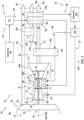
FIG. 1 is a partial schematic illustration of an aircraft propulsion system. -
FIG. 2 is a partial schematic illustration of a fuel system for the aircraft propulsion system. -
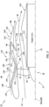
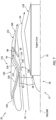
FIGS. 3 and4 are partial schematic sectional illustrations of the aircraft propulsion system with a heat exchange system in various modes of operation. -
FIG. 5 is a partial perspective illustration of the aircraft propulsion system with a ram air scoop. -
FIG. 6 is a partial perspective illustration of the aircraft propulsion system with a NACA duct scoop. -
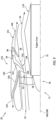
FIGS. 7-9 are partial schematic sectional illustrations of the aircraft propulsion system with the heat exchange system in various other modes of operation. -
FIG. 1 illustrates apropulsion system 20 for an aircraft. The aircraft may be an airplane, a drone (e.g., an unmanned aerial vehicle (UAV)) or any other manned or unmanned aerial vehicle or system. Theaircraft propulsion system 20 ofFIG. 1 includes agas turbine engine 22 and a water and heatenergy recovery system 24. - The
turbine engine 22 includes a propulsor section 26 (e.g., a fan section), acompressor section 27, acombustor section 28, aturbine section 29 and anexhaust section 30. Briefly, thecompressor section 27, thecombustor section 28 and theturbine section 29 may form acore 32 of theturbine engine 22, whichengine core 32 powers operation of thepropulsor section 26. Theturbine section 29 ofFIG. 1 includes a high pressure turbine (HPT)section 29A and a low pressure turbine (LPT)section 29B, whichLPT section 29B is a power turbine (PT) section for thepropulsor section 26. - Each
engine section - The propulsor rotor 34 (e.g., a fan rotor) of
FIG. 1 is connected to and driven by theLPT rotor 37 through alow speed shaft 40. At least (or only) thepropulsor rotor 34, thelow speed shaft 40 and theLPT rotor 37 may form a lowspeed rotating assembly 42; e.g., a low speed spool. This lowspeed rotating assembly 42 may be configured as a direct drive rotating assembly where thepropulsor rotor 34 and theLPT rotor 37 rotate at a common speed. The lowspeed rotating assembly 42, however, may alternatively be configured as a geared rotating assembly with a geartrain 44 (e.g., an epicyclic gearbox) coupled between thepropulsor rotor 34 and theLPT rotor 37. With such an arrangement, thepropulsor rotor 34 rotates at a different (e.g., slower) speed than theLPT rotor 37. Thecompressor rotor 35 ofFIG. 1 is connected to and driven by theHPT rotor 36 through ahigh speed shaft 46. At least (or only) thecompressor rotor 35, thehigh speed shaft 46 and theHPT rotor 36 may form a highspeed rotating assembly 48; e.g., a high speed spool. Each of theengine rotating assemblies rotational axis - During operation of the
turbine engine 22 ofFIG. 1 , air enters theturbine engine 22 through anairflow inlet 52 into theaircraft propulsion system 20. This air is directed through thepropulsor section 26 and into a core flowpath 54 (e.g., annular core flowpath) and a bypass flowpath 56 (e.g., annular bypass flowpath). Thecore flowpath 54 extends sequentially through thecompressor section 27, thecombustor section 28, theHPT section 29A, theLPT section 29B and theexhaust section 30 from anairflow inlet 58 into thecore flowpath 54 to a combustion products exhaust 60 from thecore flowpath 54. The air within thecore flowpath 54 may be referred to as "core air". Thebypass flowpath 56 extends through a bypass duct and bypasses (e.g., is radially outboard of and extends along) theengine core 32, from anairflow inlet 62 into thebypass flowpath 56 to anairflow exhaust 64 from thebypass flowpath 56. The air within thebypass flowpath 56 may be referred to as "bypass air". Briefly, thecore inlet 58 and thebypass inlet 62 may each be fluidly coupled with, adjacent and downstream of thepropulsor section 26. Thecore inlet 58 and thebypass inlet 62 may also be axially aligned along the axis 50 (seeFIGS. 3 and4 ). Theairflow inlet 52, thecore exhaust 60 and thebypass exhaust 64 may each be fluidly coupled (e.g., independently, directly) with anenvironment 66 external to theaircraft propulsion system 20; e.g., an external environment outside of the aircraft. - The core air is compressed by the
compressor rotor 35 and directed into a combustion chamber 68 (e.g., an annular combustion chamber) of a combustor 70 (e.g., an annular combustor) in thecombustor section 28. Fuel is injected into thecombustion chamber 68 by one or more fuel injectors 72 (see alsoFIG. 2 ) and mixed with the compressed core air to provide a fuel-air mixture. This fuel-air mixture is ignited and combustion products thereof flow through and sequentially cause theHPT rotor 36 and theLPT rotor 37 to rotate. The rotation of theHPT rotor 36 drives rotation of thecompressor rotor 35 and, thus, compression of the air received from thecore inlet 58. The rotation of theLPT rotor 37 drives rotation of thepropulsor rotor 34, which propels the bypass air through and out of thebypass flowpath 56. The propulsion of the bypass air may account for a majority of thrust generated by theaircraft propulsion system 20. - Referring to
FIG. 2 , theaircraft propulsion system 20 includes afuel system 74 for delivering the fuel to thecombustor section 28 and itscombustor 70. Thisfuel system 74 includes the one ormore fuel injectors 72, afuel source 76 and afuel circuit 78. Thefuel source 76 ofFIG. 2 includes afuel reservoir 80 and/or afuel flow regulator 82; e.g., a valve and/or a pump. Thefuel reservoir 80 is configured to store the fuel before, during and/or after turbine engine operation. Thefuel reservoir 80, for example, may be configured as or otherwise include a tank, a cylinder, a pressure vessel, a bladder or any other type of fuel storage container. Thefuel flow regulator 82 is configured to direct and/or meter a flow of the fuel from thefuel reservoir 80 to thefuel injectors 72. Thefuel injectors 72 may be arranged circumferentially about the axis 50 in an array. Eachfuel injector 72 is configured to direct the fuel received from thefuel source 76 into thecombustion chamber 68 for mixing with the compressed core air to provide the fuel-air mixture. - The
turbine engine 22 ofFIG. 1 may be configured as a non-hydrocarbon turbine engine / a hydrocarbon free turbine engine. Theturbine engine 22, for example, may be configured as a hydrogen fueled turbine engine. The fuel injected into thecombustion chamber 68 by thefuel injectors 72, for example, may be hydrogen (H2) fuel; e.g., H2 gas. The present disclosure, however, is not limited to hydrogen fueled turbine engines nor to non-hydrocarbon turbine engines. Theturbine engine 22, for example, may also or alternatively be fueled by another non-hydrocarbon fuel such as, but not limited to, cracked ammonia (NH3). Theturbine engine 22 may still also or alternatively be fueled using any other fuel, including hydrocarbon fuels (e.g., kerosene, jet fuel, sustainable aviation fuel (SAF), etc.), which produces combustion products that include water (H2O) vapor. - The
recovery system 24 ofFIG. 1 is configured to recover at least some of the water produced by the combustion of the fuel-air mixture within thecombustion chamber 68 and/or otherwise introduced into the core flowpath 54 (e.g., for intercooling, etc.). Therecovery system 24 is also configured to direct at least some of the recovered water back to theturbine engine 22 for use in itsengine core 32; e.g., in thecompressor section 27 and/or in thecombustor section 28. Therecovery system 24 ofFIG. 1 , for example, includes a heat exchanger configured as acondenser 84, and awater flow circuit 86. - The
condenser 84 ofFIG. 1 includes an internalcombustion products passage 88, aninternal air passage 90 and aninternal fuel passage 92, where each of thesecondenser passages combustion products passage 88 forms a portion of thecore flowpath 54 which extends longitudinally through thecondenser 84. This portion of thecore flowpath 54 is arranged between theLPT rotor 37 and thecore exhaust 60. Thecondenser 84 ofFIG. 1 , for example, is arranged in theexhaust section 30. Theair passage 90 forms a portion of aheat exchange flowpath 94 which extends longitudinally through thecondenser 84. Thefuel passage 92 forms a portion of thefuel circuit 78 longitudinally through thecondenser 84. This portion of thefuel circuit 78 may be arranged between thefuel source 76 and one or more or all of thefuel injectors 72. - The
condenser 84 ofFIG. 1 is schematically shown as a single pass, parallel flow heat exchanger between thecombustion products passage 88 and theair passage 90, and thecondenser 84 is schematically shown as a single pass, crossflow heat exchanger between thecombustion products passage 88 and thefuel passage 92. Thecondenser 84 of the present disclosure, however, is not limited to such an exemplary arrangement. Thecondenser 84, for example, may alternatively be configured as a crossflow heat exchanger or a counterflow heat exchanger between thecombustion products passage 88 and theair passage 90. Thecondenser 84 may also or alternatively be configured as a parallel flow heat exchanger or a counterflow heat exchanger between thecombustion products passage 88 and thefuel passage 92. Any one or more of thecondenser passages condenser 84. Moreover, while thecondenser 84 is shown with the three condenser passages, it is contemplated thefuel passage 92 may be omitted in other embodiments and/or incorporated into another condenser arranged along thecore flowpath 54. - The
flow circuit 86 ofFIG. 1 is configured with one or more circuit paths 96-98; e.g., circuit legs. Thisflow circuit 86 includes awater separator 100, awater reservoir 102, awater flow regulator 104 and another heat exchanger configured as anevaporator 106. - The
water separator 100 is arranged with thecondenser 84 along thecore flowpath 54. Thewater separator 100, for example, may be configured as or otherwise include a gutter integrated with (e.g., into) thecondenser 84, or connected downstream of thecondenser 84 along thecore flowpath 54. However, various other types of separators are known in the art, and the present disclosure is not limited to any particular ones thereof. Thewater separator 100, for example, may alternatively be configured as or otherwise include an impingement surface, a centrifugal water separator and/or otherwise. - The
water reservoir 102 is configured to store a quantity of water before, during and/or after recovery system operation. Thewater reservoir 102, for example, may be configured as or otherwise include a tank, a cylinder, a pressure vessel, a bladder or any other type of water storage container. An inlet to thewater reservoir 102 is fluidly coupled with an outlet from thewater separator 100 along theflow circuit 86 and itssource circuit path 96. - The
water flow regulator 104 is configured to direct and/or meter a quantity of the water stored within thewater reservoir 102 to the liquidwater circuit path 97 and/or the gaseous water (e.g., steam)circuit path 98. Thewater flow regulator 104 ofFIG. 1 , for example, is arranged at an intersection between an outlet from thesource circuit path 96, an inlet to the liquidwater circuit path 97 and an inlet to the gaseouswater circuit path 98. Thewater reservoir 102 may thereby be fluidly coupled between thewater flow regulator 104 and thewater separator 100 along theflow circuit 86 and itssource circuit path 96. - The
evaporator 106 ofFIG. 1 includes an internalcombustion products passage 108 and an internal fluid (e.g., liquid water-to-gaseous water)passage 110, where each of theseevaporator passages combustion products passage 108 forms a portion of thecore flowpath 54 which extends longitudinally through theevaporator 106. This portion of thecore flowpath 54 is arranged between theLPT rotor 37 and thecore exhaust 60. Theevaporator 106 ofFIG. 1 , for example, is arranged in theexhaust section 30. More particularly, theevaporator 106 ofFIG. 1 is arranged along thecore flowpath 54 between theLPT section 29B and thecondenser 84; however, the present disclosure is not limited to such an exemplary arrangement depending on recovery system heating and cooling requirements. Thefluid passage 110 forms a portion of theflow circuit 86 and its gaseouswater circuit path 98 which extends longitudinally through theevaporator 106. This portion of theflow circuit 86 ofFIG. 1 and its gaseouswater circuit path 98 is arranged downstream of thewater flow regulator 104. - The
evaporator 106 ofFIG. 1 is schematically shown as a single pass, counterflow heat exchanger between thecombustion products passage 108 and thefluid passage 110. Theevaporator 106 of the present disclosure, however, is not limited to such an exemplary arrangement. Theevaporator 106, for example, may alternatively be configured as a parallel flow heat exchanger or a crossflow heat exchanger between thecombustion products passage 108 and thefluid passage 110. Moreover, any one or more of theevaporator passages 108 and/or 110 may make two or more passes within theevaporator 106. - The liquid
water circuit path 97 and the gaseouswater circuit path 98 are fluidly coupled in parallel with and downstream of thesource circuit path 96. The liquidwater circuit path 97 ofFIG. 1 extends longitudinally out from the intersection / thewater flow regulator 104 to one or more liquid water circuit components 112 (one shown inFIG. 1 for ease of illustration) of theturbine engine 22 and itsengine core 32. One or more of these liquidwater circuit components 112 may each be configured as or otherwise include a liquid water injector. Each liquid water injector may be configured to inject liquid water into thecore flowpath 54. One or more of the liquidwater circuit components 112 may also or alternatively be configured as an outlet for introducing the liquid water for cooling the core air along thecompressor section 27; e.g., intercooling the core air upstream, along and/or downstream of thecompressor rotor 35. The present disclosure, however, is not limited to the foregoing exemplary components which utilize the liquid water. In particular, various other uses for liquid water in a turbine engine are known in the art, and the present disclosure is not limited to any particular one thereof. - The gaseous
water circuit path 98 ofFIG. 1 extends longitudinally out from the intersection / thewater flow regulator 104 to one or more gaseous water circuit components 114 (one shown inFIG. 1 for ease of illustration) of theturbine engine 22 and itsengine core 32. One or more of these gaseouswater circuit components 114 may each be configured as or otherwise include a steam injector. Each steam injector may be configured to inject gaseous water - steam - into thecore flowpath 54; e.g., in thecombustion chamber 68. One or more of the gaseouswater circuit components 114 may also or alternatively be configured as an outlet for introducing the gaseous water for cooling structures and/or fluids along and/or within thecombustor section 28 and/or theturbine section 29. The present disclosure, however, is not limited to the foregoing exemplary components which utilize the gaseous water - steam. In particular, various other uses for gaseous water in a turbine engine are known in the art, and the present disclosure is not limited to any particular one thereof. - During operation of the
recovery system 24, cooling air may be directed into thecondenser 84 and itsair passage 90. As described below in further detail, this cooling air may be some of the bypass air bled from thebypass flowpath 56 and/or ambient air (e.g., ram air) from theexternal environment 66 outside of the aircraft. The fuel may be directed into thecondenser 84 and itsfuel passage 92. The combustion products, including the water vapor, are directed into thecondenser 84 and itscombustion products passage 88. Thecondenser 84 exchanges heat energy between the various working fluids - the cooling air, the fuel and the combustion products - flowing within thecondenser 84. During normal turbine engine operation, the combustion products flowing within thecombustion products passage 88 are (e.g., significantly) warmer than the cooling air flowing within theair passage 90 and the fuel flowing within thefuel passage 92. Thecondenser 84 is thereby operable to cool the combustion products using the cooling air and/or the fuel. This cooling of the combustion products may condense at least some of the water vapor (e.g., water in a gaseous phase, gaseous water) flowing within thecombustion products passage 88 into liquid water droplets (e.g., water in a liquid phase). A quantity (e.g., at least some or all) of the liquid water may be collected and separated from the remaining gaseous combustion products within thecore flowpath 54 by thewater separator 100. Thewater separator 100 may subsequently direct the separated liquid water into theflow circuit 86 and itssource circuit path 96 to thewater reservoir 102 for (e.g., temporary) storage. - The
water flow regulator 104 may selectively direct (e.g., pump, meter, guide, etc.) a quantity of the liquid water from thewater reservoir 102 into the liquidwater circuit path 97. The liquidwater circuit path 97 may direct this quantity of the liquid water to the liquidwater circuit components 112 for use with / within theengine core 32 and, for example, itscompressor section 27. - The
water flow regulator 104 may also or alternatively selectively direct a quantity of the liquid water from thewater reservoir 102 into the gaseouswater circuit path 98. The gaseouswater circuit path 98 may direct this quantity of the liquid water into thefluid passage 110 of theevaporator 106. The combustion products are also directed into theevaporator 106 and itscombustion products passage 108. Theevaporator 106 exchanges heat energy between the various working fluids - the water and the combustion products - flowing within theevaporator 106. During normal turbine engine operation, the combustion products flowing within thecombustion products passage 108 are (e.g., significantly) warmer than the liquid water flowing into and within thefluid passage 110. Theevaporator 106 is thereby operable to heat the water using the combustion products. This heating of the liquid water within theevaporator 106 and itsfluid passage 110 may evaporate at least some or all of the liquid water flowing within thefluid passage 110 into gaseous water - steam. The gaseouswater circuit path 98 may direct a quantity of this gaseous water from theevaporator 106 to the gaseouswater circuit components 114 for use with / within theengine core 32 and, for example, itscombustor section 28 and/or itsturbine section 29. - Referring to
FIGS. 3 and4 , theaircraft propulsion system 20 includes anengine housing 116 for housing theturbine engine 22 and itspropulsor section 26 and itsengine core 32. Thisengine housing 116 includes a housinginner structure 118 and a housingouter structure 120. - The
inner structure 118 includes an inner case 122 (schematically shown) and aninner nacelle 124. Theinner case 122 houses theengine core 32 and its engine sections 27-29B (seeFIG. 1 ). Theinner nacelle 124 houses and provides an aerodynamic cover over at least theinner case 122. Theinner nacelle 124 ofFIGS. 3 and4 forms an inner peripheral boundary of thebypass flowpath 56. - The
outer structure 120 includes anouter case 126 and anouter nacelle 128. Theouter case 126 houses at least thepropulsor section 26. Theouter nacelle 128 houses and provides an aerodynamic cover over at least theouter case 126. Theouter nacelle 128 ofFIGS. 3 and4 is also disposed radially outboard of, extends circumferentially about (e.g., circumscribes) and extends axially along (e.g., overlaps) at least a forward portion of theinner nacelle 124. Theouter structure 120 and itsmembers FIGS. 3 and4 form an outer peripheral boundary of thebypass flowpath 56. Theinner structure 118 and itsinner nacelle 124 and theouter structure 120 and itsmembers bypass flowpath 56 within theengine housing 116. Thebypass flowpath 56 extends longitudinally (e.g., generally axially) within the engine housing 116 (e.g., radially between theinner structure 118 and the outer structure 120) from thebypass inlet 62 to thebypass exhaust 64. - The
aircraft propulsion system 20 ofFIGS. 3 and4 also includes aheat exchange system 130. Thisheat exchange system 130 includes aheat exchange duct 132, an exterior orifice 134 (e.g., an exterior inlet and/or outlet), an interior orifice 136 (e.g., an interior inlet) and a coolingair flow regulator 138. Theheat exchange system 130 also includes thecondenser 84 which is disposed within theheat exchange duct 132. Thecondenser 84 ofFIGS. 3 and4 , for example, extends across theheat exchange flowpath 94 within theheat exchange duct 132. - The
heat exchange duct 132 is formed by and internal to theengine housing 116 and itsouter structure 120. Theheat exchange duct 132 ofFIGS. 3 and4 , for example, includes aninner duct wall 140 and anouter duct wall 142. Theinner duct wall 140 is radially outboard of and may partially form the outer peripheral boundary of thebypass flowpath 56. Theouter duct wall 142 is spaced radially outboard of theinner duct wall 140 and may partially form an exterior of theaircraft propulsion system 20 and itsengine housing 116. More particularly, theouter duct wall 142 ofFIGS. 3 and4 forms an aerodynamicexterior surface 144 of theengine housing 116 and itsouter structure 120. Theheat exchange duct 132 and itsduct walls heat exchange duct 132 to anexhaust 146 from theheat exchange flowpath 94 at an aft, downstream end of theheat exchange duct 132. Thisheat exchange duct 132 also extends (e.g., partially or completely) circumferentially about the axis 50 within theouter structure 120. - The
exterior orifice 134 is formed by theengine housing 116 and itsouter structure 120. Theexterior orifice 134 is disposed along the exterior of theengine housing 116 and itsouter structure 120. Referring toFIG. 5 , theexterior orifice 134 may be formed by a ram air scoop at the exterior of theengine housing 116. Theouter structure 120 ofFIG. 5 , for example, includes ascoop 148 which projects radially out from thehousing exterior surface 144. Theexterior orifice 134 forms an opening into thescoop 148. The present disclosure, however, is not limited to such an exemplary scoop nor exterior orifice configuration. For example, referring toFIG. 6 , thescoop 148 may alternatively project radially into theouter structure 120 from thehousing exterior surface 144. Thescoop 148 ofFIG. 6 , for example, is configured as a NACA duct scoop. Referring toFIGS. 3 and4 , theexterior orifice 134 may be fluidly coupled to theflow regulator 138 by anouter duct 150. Thisouter duct 150 is formed by and internal to theengine housing 116 and itsouter structure 120. Theouter duct 150 ofFIGS. 3 and4 extends longitudinally from theexterior orifice 134 to theflow regulator 138. - The
interior orifice 136 is formed by theengine housing 116 and itsouter structure 120. Theinterior orifice 136 is disposed along thebypass flowpath 56 and its outer peripheral boundary. Theinterior orifice 136 ofFIGS. 3 and4 , for example, is configured as a port through a wall forming the outer peripheral boundary of thebypass flowpath 56; e.g., a wall of theouter structure 120. - The
flow regulator 138 is configured to selectively fluidly couple theexterior orifice 134 and/or theinterior orifice 136 to theheat exchange duct 132. Theflow regulator 138 ofFIGS. 3 and4 , for example, includes an outer door 152 (or another valve element) and an inner door 154 (or another valve element). An aft, downstream end of theouter door 152 of may be pivotally connected to theheat exchange duct 132 and itsouter duct wall 142. An aft, downstream end of theinner door 154 may be pivotally connected to theheat exchange duct 132 and itsinner duct wall 140. Each of theseflow regulator doors flow regulator doors flow regulator 138 may be operated in a ram air mode of operation (seeFIG. 3 ) or a forced induction mode of operation (seeFIG. 4 ). - During the ram air mode of
FIG. 3 , both of theflow regulator doors outer door 152, for example, is moved to open a passage between theouter duct 150 and theheat exchange duct 132. Theflow regulator 138 may thereby fluidly couple theheat exchange duct 132 with theouter duct 150 and, thus, theexterior orifice 134. Theinner door 154 is moved to (e.g., completely) close theinterior orifice 136. Theflow regulator 138 may thereby fluidly decouple theinterior orifice 136 from theheat exchange duct 132. With this arrangement ofFIG. 3 , theheat exchange flowpath 94 extends from theexterior orifice 134, sequentially through theouter duct 150, theflow regulator 138 and theheat exchange duct 132, to the heatexchange flowpath exhaust 146. Theflow regulator 138 may operate in this ram air mode when, for example, the aircraft and itsaircraft propulsion system 20 are moving relatively fast relative to the ambient air in theexterior environment 66; e.g., during aircraft cruise. - During the forced induction mode of
FIG. 4 , both of theflow regulator doors outer door 152, for example, is moved to (e.g., completely) close the passage between theouter duct 150 and theheat exchange duct 132. Theflow regulator 138 may thereby fluidly decouple theheat exchange duct 132 from theouter duct 150 and, thus, theexterior orifice 134. Theinner door 154 is moved to open theinterior orifice 136. Theflow regulator 138 may thereby fluidly couple theinterior orifice 136 to theheat exchange duct 132. With this arrangement ofFIG. 4 , theheat exchange flowpath 94 extends from theinterior orifice 136, sequentially through theflow regulator 138 and theheat exchange duct 132, to the heatexchange flowpath exhaust 146. Theflow regulator 138 may operate in this forced induction mode when, for example, the aircraft and itsaircraft propulsion system 20 are moving relatively slow (e.g., horizontally) relative to the ambient air in theexterior environment 66; e.g., during aircraft taxi, aircraft takeoff or landing, initial aircraft ascent, final aircraft descent, etc. - In some embodiments, the
heat exchange system 130 may (or may not) also include abypass passage 156. Thisbypass passage 156 may extend from theflow regulator 138 to the exterior of theengine housing 116. During the ram air mode ofFIG. 3 , theouter door 152 may (e.g., completely) close off an opening to thebypass passage 156. Theflow regulator 138 may thereby fluidly decouple theouter duct 150 from thebypass passage 156. However, during the forced induction mode ofFIG. 4 , theouter door 152 may open the opening to thebypass passage 156. Theflow regulator 138 may thereby fluidly couple theouter duct 150 to thebypass passage 156. Provision of thisbypass passage 156 may reduce drag and/or back pressure within theouter duct 150 while theouter duct 150 is otherwise closed off by theouter door 152. - While the operation of the
flow regulator 138 is described above with respect to the ram air mode ofFIG. 3 and the forced induction mode ofFIG. 4 , the present disclosure is not limited to such exemplary modes of operation. For example, referring toFIG. 7 , theflow regulator 138 may be operated in a transition mode of operation for a period of time. During this transition mode, theouter door 152 and theinner door 154 may be moved to intermediate positioned where theheat exchange duct 132 is fluidly coupled (e.g., in parallel) to both the exterior orifice 134 (e.g., via the outer duct 150) and theinterior orifice 136. Theheat exchange duct 132 may thereby receive its cooling air from both thebypass flowpath 56 and theexterior environment 66. Moreover, while the above modes of operation facilitate fluid coupling of theexterior orifice 134 and/or theinterior orifice 136 to theheat exchange duct 132, theflow regulator 138 may alternatively (e.g., completely) fluidly decouple theexterior orifice 134 and theinterior orifice 136 from theheat exchange duct 132. For example, referring toFIG. 8 , theflow regulator 138 may be operated in a thrust reverser mode of operation. During this thrust reverser mode, theflow regulator 138 may fluidly couple theinterior orifice 136 to theouter duct 150 and, thus, theexterior orifice 134. Theouter door 152 may meet (e.g., engage) theinner door 154, and both theouter door 152 and theinner door 154 may project partially into thebypass flowpath 56. Theflow regulator 138 may thereby divert at least some of the bypass air out of thebypass flowpath 56, through theinterior orifice 136 and theouter duct 150, to theexterior orifice 134 to provide reverse thrust. Here, theinterior orifice 136, theflow regulator 138 and the exterior orifice 134 (as well as theouter duct 150 ofFIG. 8 ) may form a thrust reverser for theaircraft propulsion system 20. In other embodiments, referring toFIG. 9 , theouter door 152 may be (e.g., slightly) spaced from theinner door 154 to facilitate flow of some bypass air into theheat exchange duct 132. With such an arrangement, thecondenser 84 may continue to condense at least some of the water vapor. - For ease of description, the
heat exchange system 130 is described above with a single (e.g., arcuate or annular)heat exchange flowpath 94 and asingle condenser 84. In other embodiments, however, multiple of thecondensers 84 may be arranged with theheat exchange flowpath 94. In still other embodiments, theheat exchange system 130 may include multiple of theheat exchange flowpaths 94 arranged circumferentially about the axis 50, where eachheat exchange flowpath 94 is associated with its own condenser (or multiple condensers). Theheat exchange flowpaths 92, for example, may be disposed to opposing lateral sides of theaircraft propulsion system 20. Moreover, while theheat exchange system 130 is described above as including thecondenser 84 for therecovery system 24, it is contemplated such theheat exchange system 130 of the present disclosure may alternatively be configured for other applications. One or more other types of heat exchangers may also or alternatively be disposed within theheat exchange duct 132. Examples of these other heat exchangers include, but are not limited to, a lubricant cooler, an air cooler, and the like. - The
heat exchange system 130 may be included with various turbine engines other than the one described above. Theheat exchange system 130, for example, may be included in a geared turbine engine where a geartrain connects one or more shafts to one or more rotors. Alternatively, theheat exchange system 130 may be included in a turbine engine configured without a geartrain. Theheat exchange system 130 may be included in a geared or non-geared turbine engine configured with a single spool, with two spools, or with more than two spools. Moreover, while thepropulsor rotor 34 is described above as a ducted fan rotor, it is contemplated thepropulsor rotor 34 may alternatively be configured as another type of bladed rotor; e.g., a compressor rotor, etc. The present disclosure therefore is not limited to any particular types or configurations of turbine engines. - While various embodiments of the present disclosure have been described, it will be apparent to those of ordinary skill in the art that many more embodiments and implementations are possible within the scope of the disclosure. For example, the present disclosure as described herein includes several aspects and embodiments that include particular features. Although these features may be described individually, it is within the scope of the present disclosure that some or all of these features may be combined with any one of the aspects and remain within the scope of the disclosure. Accordingly, the present disclosure is not to be restricted except in light of the attached claims and their equivalents.
Claims (15)
- A propulsion system (20) for an aircraft, comprising:a propulsor rotor (34);an engine core (32) configured to power rotation of the propulsor rotor (34) about an axis (50);a housing (116) including an inner structure (118) and an outer structure (120), the inner structure (118) housing the engine core (32), the outer structure (120) housing the propulsor rotor (34), and the outer structure (120) radially outboard of and axially overlapping the inner structure (118);a flowpath (54) downstream of the propulsor rotor (34) and radially between the inner structure (118) and the outer structure (120); anda heat exchange system (130) including a duct (132), an exterior orifice (134), an interior orifice (136), a flow regulator (138) and a heat exchanger (84) disposed within the duct (132), the exterior orifice (134) formed by the outer structure (120) and disposed along an exterior of the housing (116), the interior orifice (136) formed by the outer structure (120) and disposed along the flowpath (54), and the flow regulator (138) configured to selectively fluidly couple the exterior orifice (134) and the interior orifice (136) to the duct (132).
- The propulsion system (20) of claim 1, wherein, during a mode of operation, the flow regulator (138) is configured to:fluidly couple the exterior orifice (134) to the duct (132); andfluidly decouple the interior orifice (136) from the duct (132).
- The propulsion system (20) of claim 1 or 2, wherein, during a mode of operation, the flow regulator (138) is configured to:fluidly couple the interior orifice (136) to the duct (132); andfluidly decouple the exterior orifice (134) from the duct (132).
- The propulsion system (20) of claim 1, 2 or 3, wherein:the heat exchange system (130) further includes a bypass passage (156); andduring a mode of operation, the flow regulator (138) is further configured to fluidly couple the exterior orifice (134) to the bypass passage (156).
- The propulsion system (20) of any preceding claim, wherein, during a mode of operation, the flow regulator (138) is configured to fluidly couple the interior orifice (136) and the exterior orifice (134) to the duct (132).
- The propulsion system (20) of any preceding claim, wherein, during a mode of operation, the flow regulator (138) is configured to:fluidly decouple the interior orifice (136) and the exterior orifice (134) from the duct (132); andfluidly couple the interior orifice (136) to the exterior orifice (134).
- The propulsion system (20) of any preceding claim, wherein, during a mode of operation, the flow regulator (138) is configured to direct flow from the flowpath (54), through the interior orifice (136), to the exterior orifice (134) to provide reverse thrust.
- The propulsion system (20) of any preceding claim, wherein:the duct (132) is formed by the outer structure (120) and radially outboard of the flowpath (54); and/orthe propulsor rotor (34) comprises a fan rotor.
- The propulsion system (20) of any preceding claim, wherein:the outer structure (120) includes an exterior surface (144) and a scoop (148);the scoop (148) projects out from the exterior surface (144), or the scoop (148) projects into the outer structure (120) from the exterior surface (144); andthe exterior orifice (134) is formed by the scoop (148).
- The propulsion system (20) of any preceding claim, wherein the engine core (32) comprises a compressor section (27), a combustor section (28) and a turbine section (29).
- The propulsion system (20) of claim 10, further comprising:a recovery system (24) comprising the heat exchanger (84), a separator (100) and a flow circuit (86); anda core flowpath (54) extending sequentially through the compressor section (27), the combustor section (28), the turbine section (29) and the heat exchanger from an inlet (52) into the flowpath (54) to an exhaust (60) from the flowpath (54);the recovery system (24) configured to condense water vapor flowing within the core flowpath (54) into liquid water using the heat exchanger (84), and the recovery system (24) configured to direct the liquid water from the core flowpath (54) into the flow circuit (86) using the separator (100).
- The propulsion system (20) of claim 11, wherein:the recovery system (24) is configured to direct at least some of the liquid water through the flow circuit (86) to the engine core (32); and/orthe recovery system (24) further includes an evaporator (106) through which the core flowpath (54) extends, and the recovery system (24) is configured to evaporate at least some of the liquid water into steam and direct the steam through the flow circuit (86) to the engine core (32).
- The propulsion system (20) of any preceding claim, further comprising:a fuel system (74) for the engine core (32);the fuel system (74) including a fuel source (76) and a fuel injector (72) in the engine core (32); andthe fuel system (74) configured to direct fuel from the fuel source (76), through the heat exchanger (84), to the fuel injector (72).
- A propulsion system (20) for an aircraft, comprising:a housing (116);a turbine engine (22) within the housing (116), the turbine engine (22) comprising a bladed rotor (34);a flowpath (54) downstream of the bladed rotor (34); anda heat exchange system (130) including a duct (132), an exterior orifice (134), an interior orifice (136), a flow regulator (138) and a heat exchanger (84) disposed within the duct (132), the exterior orifice (134) formed by and disposed along an exterior of the housing (116), the interior orifice (136) formed by the housing (116) and disposed along the flowpath (54), and the flow regulator (138) configured to:fluidly couple the exterior orifice (134) to the duct (132) during a first mode; andfluidly couple the interior orifice (136) to the duct (132) during a second mode, wherein, optionally:the flow regulator (138) is further configured to fluidly couple the interior orifice (136) to the exterior orifice (134) and at least substantially fluidly decouple the exterior orifice (134) and the interior orifice (136) from the duct (132) in a third mode; and/orthe propulsion system (20) further comprises:a recovery system (24) comprising the heat exchanger (84) and a separator (100);a core flowpath (54) extending through a core (32) of the turbine engine (22) and the heat exchanger (84) from an inlet (52) into the flowpath (54) to an exhaust (60) from the flowpath (54);the recovery system (24) configured to condense water vapor flowing within the core flowpath (54) into liquid water using the heat exchanger (84), and the recovery system (24) configured to extract at least some of the liquid water from the core flowpath (54) using the separator (100).
- A method of operation, comprising:directing bypass air into a bypass flowpath (56) of a propulsion system (20) of an aircraft;during a first mode of operation, directing a first portion of the bypass air through the bypass flowpath (56) to an exhaust (146) from the bypass flowpath (56), and directing a second portion of the bypass air through an interior orifice (136) to a heat exchanger (84) outside of the flowpath (56); andduring a second mode of operation, directing ambient air from outside of the propulsion system (20) through an exterior orifice (134) to the heat exchanger (84);wherein the heat exchanger (84) is fluidly decoupled from the exterior orifice (134) during the first mode of operation, and the heat exchanger (84) is fluidly decoupled from the interior orifice (136) during the second mode of operation.
Applications Claiming Priority (1)
| Application Number | Priority Date | Filing Date | Title |
|---|---|---|---|
| US18/243,456 US12163488B1 (en) | 2023-09-07 | 2023-09-07 | Selectable inlet for aircraft propulsion system heat exchanger |
Publications (1)
| Publication Number | Publication Date |
|---|---|
| EP4520939A1 true EP4520939A1 (en) | 2025-03-12 |
Family
ID=91853766
Family Applications (1)
| Application Number | Title | Priority Date | Filing Date |
|---|---|---|---|
| EP24186916.3A Pending EP4520939A1 (en) | 2023-09-07 | 2024-07-05 | Selectable inlet for aircraft propulsion system heat exchanger |
Country Status (2)
| Country | Link |
|---|---|
| US (1) | US12163488B1 (en) |
| EP (1) | EP4520939A1 (en) |
Cited By (1)
| Publication number | Priority date | Publication date | Assignee | Title |
|---|---|---|---|---|
| EP4726197A1 (en) * | 2024-10-09 | 2026-04-15 | RTX Corporation | Thrust reverser in condenser exit duct |
Citations (5)
| Publication number | Priority date | Publication date | Assignee | Title |
|---|---|---|---|---|
| GB2208702A (en) * | 1987-08-18 | 1989-04-12 | Rolls Royce Plc | A heat exchanger system |
| US20060117734A1 (en) * | 2004-12-07 | 2006-06-08 | United Technologies Corporation | Supplemental oil cooler airflow for gas turbine engine |
| US20110179767A1 (en) * | 2010-01-26 | 2011-07-28 | Airbus Operations (S.A.S) | Cooling device for aircraft propeller |
| US20140369812A1 (en) * | 2012-03-02 | 2014-12-18 | Aircelle | Turbine engine nacelle fitted with a heat exchanger |
| WO2022028652A1 (en) * | 2020-08-05 | 2022-02-10 | MTU Aero Engines AG | Exhaust-gas treatment device for an aircraft engine |
Family Cites Families (7)
| Publication number | Priority date | Publication date | Assignee | Title |
|---|---|---|---|---|
| US2696712A (en) | 1949-08-16 | 1954-12-14 | Bristol Aeroplane Co Ltd | Mounting and cooling means for engine accessories |
| US7861512B2 (en) | 2006-08-29 | 2011-01-04 | Pratt & Whitney Canada Corp. | Turbofan bypass duct air cooled fluid cooler installation |
| US9108737B2 (en) | 2012-08-24 | 2015-08-18 | United Technologies Corporation | Nacelle scoop inlet |
| US10794288B2 (en) * | 2015-07-07 | 2020-10-06 | Raytheon Technologies Corporation | Cooled cooling air system for a turbofan engine |
| CA2936633C (en) * | 2015-08-12 | 2021-12-28 | Rolls-Royce North American Technologies, Inc. | Heat exchanger for a gas turbine engine propulsion system |
| US11286881B2 (en) * | 2019-10-16 | 2022-03-29 | Rolls-Royce North American Technologies Inc. | Gas turbine engine with reversible heat exchanger |
| US11760501B2 (en) * | 2021-06-11 | 2023-09-19 | Pratt & Whitney Canada Corp. | Means for handling gaseous fuel |
-
2023
- 2023-09-07 US US18/243,456 patent/US12163488B1/en active Active
-
2024
- 2024-07-05 EP EP24186916.3A patent/EP4520939A1/en active Pending
Patent Citations (5)
| Publication number | Priority date | Publication date | Assignee | Title |
|---|---|---|---|---|
| GB2208702A (en) * | 1987-08-18 | 1989-04-12 | Rolls Royce Plc | A heat exchanger system |
| US20060117734A1 (en) * | 2004-12-07 | 2006-06-08 | United Technologies Corporation | Supplemental oil cooler airflow for gas turbine engine |
| US20110179767A1 (en) * | 2010-01-26 | 2011-07-28 | Airbus Operations (S.A.S) | Cooling device for aircraft propeller |
| US20140369812A1 (en) * | 2012-03-02 | 2014-12-18 | Aircelle | Turbine engine nacelle fitted with a heat exchanger |
| WO2022028652A1 (en) * | 2020-08-05 | 2022-02-10 | MTU Aero Engines AG | Exhaust-gas treatment device for an aircraft engine |
Cited By (1)
| Publication number | Priority date | Publication date | Assignee | Title |
|---|---|---|---|---|
| EP4726197A1 (en) * | 2024-10-09 | 2026-04-15 | RTX Corporation | Thrust reverser in condenser exit duct |
Also Published As
| Publication number | Publication date |
|---|---|
| US12163488B1 (en) | 2024-12-10 |
Similar Documents
| Publication | Publication Date | Title |
|---|---|---|
| EP3904658B1 (en) | Gas turbine engines having cryogenic fuel systems | |
| EP4137686B1 (en) | Propulsion systems for aircraft | |
| EP4474624A2 (en) | Water separator for turbine engine | |
| US20210140641A1 (en) | Method and system for rotating detonation combustion | |
| EP4428348A1 (en) | Heat exchanger(s) for recovering water and/or heat energy from turbine engine combustion products | |
| EP4477856A2 (en) | Gas turbine engine with water recovery system | |
| EP4431715A2 (en) | Heat exchanger(s) for recovering water and/or heat energy from turbine engine combustion products | |
| EP4428347B1 (en) | Heat exchanger(s) for recovering water and/or heat energy from turbine engine combustion products | |
| EP4438871A1 (en) | Injecting fuel-steam mixture into turbine engine combustor | |
| EP4520939A1 (en) | Selectable inlet for aircraft propulsion system heat exchanger | |
| EP4477857A1 (en) | Gas turbine engine with hydrogen fuel system | |
| EP4524377A1 (en) | Fuel containment structure for engine fuel delivery system | |
| EP4459116A1 (en) | Aircraft powerplant with steam system and bypass | |
| EP4477855A2 (en) | Gas turbine engine system with fuel driven turbine | |
| EP4481171A1 (en) | Water actuated tip clearance control system for turbine engine | |
| EP4517066A1 (en) | Multi-fuel gas turbine engine with water injection | |
| US20260104009A1 (en) | Enhanced recuperation cycle for aircraft powerplant turbine engine | |
| EP4461943A2 (en) | Supporting elongated rotating assembly within a turbine engine | |
| EP4524383A1 (en) | Fuel containment structure for engine fuel delivery system | |
| EP4428350A1 (en) | Heat exchanger(s) for recovering water and/or heat energy from turbine engine combustion products | |
| EP4571073A2 (en) | Ventilation system for aircraft propulsion system | |
| EP4431702A1 (en) | Steam cooling turbine stator vane array |
Legal Events
| Date | Code | Title | Description |
|---|---|---|---|
| PUAI | Public reference made under article 153(3) epc to a published international application that has entered the european phase |
Free format text: ORIGINAL CODE: 0009012 |
|
| STAA | Information on the status of an ep patent application or granted ep patent |
Free format text: STATUS: THE APPLICATION HAS BEEN PUBLISHED |
|
| AK | Designated contracting states |
Kind code of ref document: A1 Designated state(s): AL AT BE BG CH CY CZ DE DK EE ES FI FR GB GR HR HU IE IS IT LI LT LU LV MC ME MK MT NL NO PL PT RO RS SE SI SK SM TR |
|
| STAA | Information on the status of an ep patent application or granted ep patent |
Free format text: STATUS: REQUEST FOR EXAMINATION WAS MADE |
|
| 17P | Request for examination filed |
Effective date: 20250912 |