EP4520932A1 - Internal combustion engine with monolithic pilot chamber structure - Google Patents
Internal combustion engine with monolithic pilot chamber structure Download PDFInfo
- Publication number
- EP4520932A1 EP4520932A1 EP24198764.3A EP24198764A EP4520932A1 EP 4520932 A1 EP4520932 A1 EP 4520932A1 EP 24198764 A EP24198764 A EP 24198764A EP 4520932 A1 EP4520932 A1 EP 4520932A1
- Authority
- EP
- European Patent Office
- Prior art keywords
- pilot chamber
- pilot
- aperture
- chamber structure
- interior surface
- Prior art date
- Legal status (The legal status is an assumption and is not a legal conclusion. Google has not performed a legal analysis and makes no representation as to the accuracy of the status listed.)
- Pending
Links
Images




Classifications
-
- F—MECHANICAL ENGINEERING; LIGHTING; HEATING; WEAPONS; BLASTING
- F02—COMBUSTION ENGINES; HOT-GAS OR COMBUSTION-PRODUCT ENGINE PLANTS
- F02B—INTERNAL-COMBUSTION PISTON ENGINES; COMBUSTION ENGINES IN GENERAL
- F02B19/00—Engines characterised by precombustion chambers
- F02B19/16—Chamber shapes or constructions not specific to sub-groups F02B19/02 - F02B19/10
- F02B19/165—The shape or construction of the pre-combustion chambers is specially adapted to be formed, at least in part, of ceramic material
-
- B—PERFORMING OPERATIONS; TRANSPORTING
- B22—CASTING; POWDER METALLURGY
- B22F—WORKING METALLIC POWDER; MANUFACTURE OF ARTICLES FROM METALLIC POWDER; MAKING METALLIC POWDER; APPARATUS OR DEVICES SPECIALLY ADAPTED FOR METALLIC POWDER
- B22F3/00—Manufacture of workpieces or articles from metallic powder characterised by the manner of compacting or sintering; Apparatus specially adapted therefor ; Presses and furnaces
- B22F3/22—Manufacture of workpieces or articles from metallic powder characterised by the manner of compacting or sintering; Apparatus specially adapted therefor ; Presses and furnaces for producing castings from a slip
- B22F3/225—Manufacture of workpieces or articles from metallic powder characterised by the manner of compacting or sintering; Apparatus specially adapted therefor ; Presses and furnaces for producing castings from a slip by injection molding
-
- B—PERFORMING OPERATIONS; TRANSPORTING
- B22—CASTING; POWDER METALLURGY
- B22F—WORKING METALLIC POWDER; MANUFACTURE OF ARTICLES FROM METALLIC POWDER; MAKING METALLIC POWDER; APPARATUS OR DEVICES SPECIALLY ADAPTED FOR METALLIC POWDER
- B22F5/00—Manufacture of workpieces or articles from metallic powder characterised by the special shape of the product
- B22F5/008—Manufacture of workpieces or articles from metallic powder characterised by the special shape of the product of engine cylinder parts or of piston parts other than piston rings
-
- B—PERFORMING OPERATIONS; TRANSPORTING
- B23—MACHINE TOOLS; METAL-WORKING NOT OTHERWISE PROVIDED FOR
- B23P—METAL-WORKING NOT OTHERWISE PROVIDED FOR; COMBINED OPERATIONS; UNIVERSAL MACHINE TOOLS
- B23P15/00—Making specific metal objects by operations not covered by a single other subclass or a group in this subclass
- B23P15/10—Making specific metal objects by operations not covered by a single other subclass or a group in this subclass pistons
-
- B—PERFORMING OPERATIONS; TRANSPORTING
- B29—WORKING OF PLASTICS; WORKING OF SUBSTANCES IN A PLASTIC STATE IN GENERAL
- B29C—SHAPING OR JOINING OF PLASTICS; SHAPING OF MATERIAL IN A PLASTIC STATE, NOT OTHERWISE PROVIDED FOR; AFTER-TREATMENT OF THE SHAPED PRODUCTS, e.g. REPAIRING
- B29C45/00—Injection moulding, i.e. forcing the required volume of moulding material through a nozzle into a closed mould; Apparatus therefor
- B29C45/0001—Injection moulding, i.e. forcing the required volume of moulding material through a nozzle into a closed mould; Apparatus therefor characterised by the choice of material
-
- C—CHEMISTRY; METALLURGY
- C04—CEMENTS; CONCRETE; ARTIFICIAL STONE; CERAMICS; REFRACTORIES
- C04B—LIME, MAGNESIA; SLAG; CEMENTS; COMPOSITIONS THEREOF, e.g. MORTARS, CONCRETE OR LIKE BUILDING MATERIALS; ARTIFICIAL STONE; CERAMICS; REFRACTORIES; TREATMENT OF NATURAL STONE
- C04B35/00—Shaped ceramic products characterised by their composition; Ceramics compositions; Processing powders of inorganic compounds preparatory to the manufacturing of ceramic products
- C04B35/515—Shaped ceramic products characterised by their composition; Ceramics compositions; Processing powders of inorganic compounds preparatory to the manufacturing of ceramic products based on non-oxide ceramics
- C04B35/56—Shaped ceramic products characterised by their composition; Ceramics compositions; Processing powders of inorganic compounds preparatory to the manufacturing of ceramic products based on non-oxide ceramics based on carbides or oxycarbides
- C04B35/565—Shaped ceramic products characterised by their composition; Ceramics compositions; Processing powders of inorganic compounds preparatory to the manufacturing of ceramic products based on non-oxide ceramics based on carbides or oxycarbides based on silicon carbide
-
- C—CHEMISTRY; METALLURGY
- C04—CEMENTS; CONCRETE; ARTIFICIAL STONE; CERAMICS; REFRACTORIES
- C04B—LIME, MAGNESIA; SLAG; CEMENTS; COMPOSITIONS THEREOF, e.g. MORTARS, CONCRETE OR LIKE BUILDING MATERIALS; ARTIFICIAL STONE; CERAMICS; REFRACTORIES; TREATMENT OF NATURAL STONE
- C04B35/00—Shaped ceramic products characterised by their composition; Ceramics compositions; Processing powders of inorganic compounds preparatory to the manufacturing of ceramic products
- C04B35/515—Shaped ceramic products characterised by their composition; Ceramics compositions; Processing powders of inorganic compounds preparatory to the manufacturing of ceramic products based on non-oxide ceramics
- C04B35/58—Shaped ceramic products characterised by their composition; Ceramics compositions; Processing powders of inorganic compounds preparatory to the manufacturing of ceramic products based on non-oxide ceramics based on borides, nitrides, i.e. nitrides, oxynitrides, carbonitrides or oxycarbonitrides or silicides
- C04B35/584—Shaped ceramic products characterised by their composition; Ceramics compositions; Processing powders of inorganic compounds preparatory to the manufacturing of ceramic products based on non-oxide ceramics based on borides, nitrides, i.e. nitrides, oxynitrides, carbonitrides or oxycarbonitrides or silicides based on silicon nitride
-
- F—MECHANICAL ENGINEERING; LIGHTING; HEATING; WEAPONS; BLASTING
- F01—MACHINES OR ENGINES IN GENERAL; ENGINE PLANTS IN GENERAL; STEAM ENGINES
- F01C—ROTARY-PISTON OR OSCILLATING-PISTON MACHINES OR ENGINES
- F01C1/00—Rotary-piston machines or engines
-
- F—MECHANICAL ENGINEERING; LIGHTING; HEATING; WEAPONS; BLASTING
- F02—COMBUSTION ENGINES; HOT-GAS OR COMBUSTION-PRODUCT ENGINE PLANTS
- F02B—INTERNAL-COMBUSTION PISTON ENGINES; COMBUSTION ENGINES IN GENERAL
- F02B19/00—Engines characterised by precombustion chambers
- F02B19/10—Engines characterised by precombustion chambers with fuel introduced partly into pre-combustion chamber, and partly into cylinder
- F02B19/1019—Engines characterised by precombustion chambers with fuel introduced partly into pre-combustion chamber, and partly into cylinder with only one pre-combustion chamber
- F02B19/108—Engines characterised by precombustion chambers with fuel introduced partly into pre-combustion chamber, and partly into cylinder with only one pre-combustion chamber with fuel injection at least into pre-combustion chamber, i.e. injector mounted directly in the pre-combustion chamber
-
- F—MECHANICAL ENGINEERING; LIGHTING; HEATING; WEAPONS; BLASTING
- F02—COMBUSTION ENGINES; HOT-GAS OR COMBUSTION-PRODUCT ENGINE PLANTS
- F02B—INTERNAL-COMBUSTION PISTON ENGINES; COMBUSTION ENGINES IN GENERAL
- F02B19/00—Engines characterised by precombustion chambers
- F02B19/12—Engines characterised by precombustion chambers with positive ignition
-
- F—MECHANICAL ENGINEERING; LIGHTING; HEATING; WEAPONS; BLASTING
- F02—COMBUSTION ENGINES; HOT-GAS OR COMBUSTION-PRODUCT ENGINE PLANTS
- F02B—INTERNAL-COMBUSTION PISTON ENGINES; COMBUSTION ENGINES IN GENERAL
- F02B53/00—Internal-combustion aspects of rotary-piston or oscillating-piston engines
- F02B53/10—Fuel supply; Introducing fuel to combustion space
-
- F—MECHANICAL ENGINEERING; LIGHTING; HEATING; WEAPONS; BLASTING
- F02—COMBUSTION ENGINES; HOT-GAS OR COMBUSTION-PRODUCT ENGINE PLANTS
- F02B—INTERNAL-COMBUSTION PISTON ENGINES; COMBUSTION ENGINES IN GENERAL
- F02B53/00—Internal-combustion aspects of rotary-piston or oscillating-piston engines
- F02B53/12—Ignition
-
- F—MECHANICAL ENGINEERING; LIGHTING; HEATING; WEAPONS; BLASTING
- F02—COMBUSTION ENGINES; HOT-GAS OR COMBUSTION-PRODUCT ENGINE PLANTS
- F02B—INTERNAL-COMBUSTION PISTON ENGINES; COMBUSTION ENGINES IN GENERAL
- F02B55/00—Internal-combustion aspects of rotary pistons; Outer members for co-operation with rotary pistons
- F02B55/14—Shapes or constructions of combustion chambers
-
- B—PERFORMING OPERATIONS; TRANSPORTING
- B29—WORKING OF PLASTICS; WORKING OF SUBSTANCES IN A PLASTIC STATE IN GENERAL
- B29C—SHAPING OR JOINING OF PLASTICS; SHAPING OF MATERIAL IN A PLASTIC STATE, NOT OTHERWISE PROVIDED FOR; AFTER-TREATMENT OF THE SHAPED PRODUCTS, e.g. REPAIRING
- B29C45/00—Injection moulding, i.e. forcing the required volume of moulding material through a nozzle into a closed mould; Apparatus therefor
- B29C45/16—Making multilayered or multicoloured articles
- B29C2045/1695—Making multilayered or multicoloured articles injecting ceramic powder layers and plastic material layers
-
- B—PERFORMING OPERATIONS; TRANSPORTING
- B33—ADDITIVE MANUFACTURING TECHNOLOGY
- B33Y—ADDITIVE MANUFACTURING, i.e. MANUFACTURING OF THREE-DIMENSIONAL [3D] OBJECTS BY ADDITIVE DEPOSITION, ADDITIVE AGGLOMERATION OR ADDITIVE LAYERING, e.g. BY 3D PRINTING, STEREOLITHOGRAPHY OR SELECTIVE LASER SINTERING
- B33Y80/00—Products made by additive manufacturing
-
- C—CHEMISTRY; METALLURGY
- C04—CEMENTS; CONCRETE; ARTIFICIAL STONE; CERAMICS; REFRACTORIES
- C04B—LIME, MAGNESIA; SLAG; CEMENTS; COMPOSITIONS THEREOF, e.g. MORTARS, CONCRETE OR LIKE BUILDING MATERIALS; ARTIFICIAL STONE; CERAMICS; REFRACTORIES; TREATMENT OF NATURAL STONE
- C04B2235/00—Aspects relating to ceramic starting mixtures or sintered ceramic products
- C04B2235/60—Aspects relating to the preparation, properties or mechanical treatment of green bodies or pre-forms
- C04B2235/602—Making the green bodies or pre-forms by moulding
- C04B2235/6026—Computer aided shaping, e.g. rapid prototyping
-
- F—MECHANICAL ENGINEERING; LIGHTING; HEATING; WEAPONS; BLASTING
- F02—COMBUSTION ENGINES; HOT-GAS OR COMBUSTION-PRODUCT ENGINE PLANTS
- F02B—INTERNAL-COMBUSTION PISTON ENGINES; COMBUSTION ENGINES IN GENERAL
- F02B19/00—Engines characterised by precombustion chambers
- F02B2019/006—Engines characterised by precombustion chambers with thermal insulation
Definitions
- This disclosure (invention) relates generally to an internal combustion engine and, more particularly, to an ignition system for the engine.
- An internal combustion engine includes an ignition system for igniting a fuel-air mixture for combustion.
- ignition system for igniting a fuel-air mixture for combustion.
- Various types and configurations of ignition systems are known in the art. While these known ignition systems have various benefits, there is still room in the art for improvement.
- an apparatus for a powerplant.
- This apparatus includes a pilot chamber structure formed as a monolithic body.
- the pilot chamber structure includes an exterior surface, an interior surface, a pilot chamber, a pilot aperture, a fuel aperture and an ignitor aperture.
- a material property of the monolithic body changes as the pilot chamber structure extends between the exterior surface and the interior surface.
- the interior surface forms an outer peripheral boundary of the pilot chamber.
- the pilot chamber is internal to the pilot chamber structure.
- the pilot aperture projects into the pilot chamber structure to the pilot chamber.
- the fuel aperture projects into the pilot chamber structure to the pilot chamber.
- the ignitor aperture projects into the pilot chamber structure to the pilot chamber.
- this apparatus includes a pilot chamber structure formed as a monolithic body.
- the pilot chamber structure includes an exterior surface, an interior surface, a pilot chamber, a pilot aperture, a fuel aperture and an ignitor aperture.
- the interior surface forms an outer peripheral boundary of the pilot chamber.
- a surface texture (or roughness) of the interior surface is different than a surface texture (or roughness) of the exterior surface.
- the pilot chamber is internal to the pilot chamber structure.
- the pilot aperture projects into the pilot chamber structure to the pilot chamber.
- the fuel aperture projects into the pilot chamber structure to the pilot chamber.
- the ignitor aperture projects into the pilot chamber structure to the pilot chamber.
- a method of manufacture is provided during which a pilot chamber structure is formed as a monolithic body.
- the forming of the pilot chamber structure includes: forming a green structure using powder injection molding; debinding the green structure to form a monolithic brown structure; and sintering the monolithic brown structure.
- the pilot chamber structure includes a pilot chamber, a pilot aperture, a fuel aperture and an ignitor aperture.
- the pilot chamber is internal to the pilot chamber structure.
- the pilot aperture projects into the pilot chamber structure to the pilot chamber.
- the fuel aperture projects into the pilot chamber structure to the pilot chamber.
- the ignitor aperture projects into the pilot chamber structure to the pilot chamber.
- the green structure may be configured as or otherwise include a monolithic green body configured as a preform of the pilot chamber structure.
- the method may also include removing a soluble core from a preform pilot chamber within the monolithic green body.
- the preform pilot chamber may be formed in the green structure during the powder injection molding using the soluble core.
- the green structure may include a first green part and a second green part.
- the debinding of the green structure may include co-debinding the first green part with the second green part to form the monolithic brown structure.
- the material property may be a density of the monolithic body.
- an interior portion of the monolithic body at least partially forming the interior surface may have a higher density than an exterior portion of the monolithic body at least partially forming the exterior surface.
- an interior portion of the monolithic body at least partially forming the interior surface may have a lower density than an exterior portion of the monolithic body at least partially forming the exterior surface.
- the material property may be a material composition of the monolithic body.
- a surface texture (or roughness) of the interior surface may be different than a surface texture (or roughness) of the exterior surface.
- a channel may project into the pilot chamber structure from the interior surface.
- the pilot chamber structure may also include an internal cavity between the interior surface and the exterior surface.
- the internal cavity may extend circumferentially about the pilot chamber.
- At least a portion of the interior surface may have a non-uniform radius of curvature.
- the monolithic body may be configured from or otherwise include a ceramic.
- the monolithic body may be configured from or otherwise include a metal.
- the apparatus may also include a housing, a primary fuel injector and an ignition system.
- the housing may form a combustion volume within the housing.
- the primary fuel injector may be configured to inject primary fuel into the combustion volume.
- the ignition system may be configured to ignite the primary fuel within the combustion volume.
- the ignition system may include a pilot fuel injector, a pilot ignitor and the pilot chamber structure.
- the pilot fuel injector may be mated with the fuel aperture and configured to inject pilot fuel into the pilot chamber.
- the pilot ignitor may be mated with the ignitor aperture and configured to ignite the pilot fuel within the pilot chamber.
- the pilot chamber may be fluidly coupled with the combustion volume through the pilot aperture.
- the present disclosure may include any one or more of the individual features disclosed above and/or below alone or in any combination thereof.
- FIG. 1 is a schematic illustration of a powerplant 20.
- This powerplant 20 may be configured for an aircraft.
- the aircraft may be an airplane, a rotorcraft, a drone (e.g., an unmanned aerial vehicle (UAV)) or any other manned or unmanned aerial vehicle and/or system.
- the powerplant 20 be configured for a land vehicle, a water vehicle, a stationary application such as a ground-based electrical power generator, or various other mobile and/or stationary applications.
- the powerplant 20 may be generally described below as an aircraft powerplant.
- the aircraft powerplant 20 of FIG. 1 includes a mechanical load 22, a drivetrain 24 and an internal combustion (IC) engine 26, where the drivetrain 24 mechanically couples the mechanical load 22 to the IC engine 26.
- IC internal combustion
- the mechanical load 22 may be configured as or otherwise include a rotor 28 mechanically driven by the IC engine 26 through the drivetrain 24.
- This driven rotor 28 may be a bladed propulsor rotor where the aircraft powerplant 20 is configured as or otherwise includes a propulsion system for the aircraft.
- the propulsor rotor may be an open (e.g., un-ducted) propulsor rotor or a ducted propulsor rotor.
- Examples of the open propulsor rotor include a propeller rotor for a turboprop propulsion system, a rotorcraft rotor (e.g., a main helicopter rotor) for a turboshaft propulsion system, a propfan rotor for a propfan propulsion system, and a pusher fan rotor for a pusher fan propulsion system.
- An example of the ducted propulsor rotor is a fan rotor for a ducted fan propulsion system.
- the present disclosure is not limited to the foregoing exemplary propulsor rotor arrangements.
- the driven rotor 28 may alternatively be a generator rotor of an electric power generator where the aircraft powerplant 20 is (or is part of) an electrical power system for the aircraft; e.g., an auxiliary power unit (APU) for the aircraft.
- APU auxiliary power unit
- the drivetrain 24 may be configured as a direct-drive drivetrain. With such a configuration, the driven rotor 28 is operable to rotate at a common (the same) rotational speed as an engine rotating structure 30 of the IC engine 26. Alternatively, the drivetrain 24 may be configured as a geared drivetrain. With such a configuration, the drive rotor is operable to rotate at a different (e.g., faster or slower) rotational speed than the engine rotating structure 30.
- the drivetrain 24, for example, may include a geartrain 32 (e.g., an epicyclic gear system) and/or another transmission device coupled between the driven rotor 28 and the engine rotating structure 30.
- the IC engine 26 may be configured as a rotary engine such as, but not limited to, a Wankel engine.
- the IC engine 26 of FIG. 2 for example, includes an engine housing 34, an engine rotor 36, a primary fuel injector 38 and an ignition system 40.
- the engine housing 34 of FIG. 2 includes an internal housing cavity 42, a primary fuel injector receptacle 44, an air intake passage 46 and a combustion products exhaust passage 48.
- the engine housing 34 is also configured for mating with the ignition system 40 as described below in further detail.
- the housing cavity 42 is formed within and enclosed by the engine housing 34.
- the primary fuel injector receptacle 44 extends through a peripheral wall 50 of the engine housing 34 from an exterior 52 of the engine housing 34 to the housing cavity 42.
- the intake passage 46 extends from an inlet into the IC engine 26, through the housing peripheral wall 50, to the housing cavity 42, which engine inlet may also be an inlet to the aircraft powerplant 20 (see FIG. 1 ).
- the exhaust passage 48 extend from the housing cavity 42, through the housing peripheral wall 50, to an exhaust from the IC engine 26, which engine exhaust may also be an exhaust from the aircraft powerplant 20 (see FIG. 1 ).
- the engine rotor 36 of FIG. 2 is disposed within the housing cavity 42, where the housing peripheral wall 50 extends circumferentially around an outer periphery of the engine rotor 36.
- the engine rotor 36 is coupled to and rotatable with the engine rotating structure 30.
- the engine rotor 36 of FIG. 2 is eccentric to the engine rotating structure 30.
- a centerline 54 of the engine rotor 36 for example, is parallel with, but offset from, a centerline 56 of the engine rotating structure 30, where the rotor centerline 54 is also a rotational axis of the engine rotor 36 and/or where the rotating structure centerline 56 is also a rotational axis of the engine rotating structure 30.
- a timing gear may be provided to control a rotational velocity of the engine rotor 36 to be slower than (e.g., 1/3 of) a rotational velocity of the engine rotating structure 30.
- the engine rotor 36 may have a non-circular, lobed cross-sectional geometry when viewed, for example, in a reference plane perpendicular to the rotor centerline 54.
- the engine rotor 36 of FIG. 2 includes a plurality of (e.g., arcuate, convex) peripheral rotor faces 58 arranged circumferentially about the rotor centerline 54. Each circumferentially neighboring (e.g., adjacent) pair of the rotor faces 58 meets at a respective apex 60 of the engine rotor 36.
- the engine rotor 36 may also include one or more rotor seals 62, where each rotor seal 62 is arranged at (e.g., on, adjacent or proximate) a respective one of the rotor apexes 60. Each rotor seal 62 is configured to sealingly engage (e.g., contact) and thereby form a seal interface with an interior 64 of the housing peripheral wall 50.
- the engine rotor 36 may be configured with various other seal elements which are omitted from the drawings for clarity. Examples of these other seal elements include, but are not limited to, gas seal element(s) and/or oil seal element(s) arranged with side faces of the engine rotor 36.
- the engine rotor 36 and the engine housing 34 may collectively form one or more combustion volumes 66A-C (generally referred to as "66") (e.g., combustion chambers, working volumes, etc.) within the engine housing 34.
- Each combustion volume 66 in particular, is formed by and between a respective one of the rotor faces 58 and a corresponding (albeit changing) portion of the housing peripheral wall 50, and circumferentially between a respective neighboring pair of the rotor seals 62.
- Each of the combustion volumes 66 moves about the centerline 54, 56 as the engine rotor 36 eccentrically rotates within the engine housing 34 and its housing cavity 42. With the rotor position of FIG.
- the combustion volume 66A is fluidly coupled with the intake passage 46 (and fluidly decoupled from the exhaust passage 48)
- the combustion volume 66B is fluidly coupled with the exhaust passage 48 (and fluidly decoupled from the intake passage 46)
- the combustion volume 66C is fluidly decoupled from the intake passage 46 and the exhaust passage 48.
- the primary fuel injector 38 is mated with / received within the primary fuel injector receptacle 44.
- the primary fuel injector 38 for example, projects into the primary fuel injector receptacle 44 and is threaded into or otherwise attached to the engine housing 34.
- air is directed through the intake passage 46 into a respective one of the combustion volumes 66.
- a volumetric measure of the respective combustion volume 66 decreases thereby compressing the air within that combustion volume 66.
- the primary fuel injector 38 directs (e.g., injects) primary fuel into the respective combustion volume 66 to mix with the air as it is being compressed to provide a fuel-air mixture.
- the fuel-air mixture within that combustion volume 66 is ignited to generate combustion products.
- the volumetric measure of the respective combustion volume 66 increases thereby facilitating expansion of the combustion products within the respective combustion volume 66 until those expanded combustion products are exhausted from the IC engine 26 through the exhaust passage 48.
- Internal combustion pressure loads of the combustion products within the respective combustion volume 66 drives rotation of the engine rotor 36 within the engine housing 34.
- the rotation of the engine rotor 36 and, thus, the rotation of the engine rotating structure 30 in turn drives rotation of the driven rotor 28 of FIG. 1 through the drivetrain 24.
- the ignition system 40 is configured to introduce a flame (e.g., a pilot flame) and/or relatively hot combustion products into the respective combustion volume 66.
- the ignition system 40 of FIG. 2 includes a pilot chamber structure 68 (schematically shown), a pilot fuel injector 70 ("pilot injector") and a pilot ignitor 72 (e.g., a spark plug, a glow plug, etc.).
- the pilot chamber structure 68 includes an internal pilot chamber 74 (e.g., a sub-chamber, a pre-ignition chamber, etc.) and a pilot aperture 76 (e.g., a transfer hole) which fluidly couples the pilot chamber 74 to the respective combustion volume 66.
- the pilot injector 70 is configured to direct (e.g., inject) pilot fuel into the pilot chamber 74.
- the pilot ignitor 72 is configured to ignite the pilot fuel within the pilot chamber 74 to generate the pilot flame and/or the pilot combustion products.
- the pilot flame and/or the pilot combustion products are directed through the pilot aperture 76 into the respective combustion volume (e.g., 66C) to ignite the fuel-air mixture within that combustion volume (e.g., 66C).
- the pilot chamber structure 68 extends longitudinally (e.g., radially relative to the axes 54, 56 of FIG. 2 ) along a longitudinal centerline 78 of the pilot chamber structure 68 between and to an outer end 80 of the pilot chamber structure 68 and an inner end 82 of the pilot chamber structure 68.
- the pilot chamber structure 68 may be formed as a plug with a T-shaped sectional geometry.
- the pilot chamber structure 68 may thereby be inserted into (e.g., plugged into) or otherwise mated with a pilot chamber structure receptacle 84 in the engine housing 34.
- the pilot chamber structure 68 of FIG. 3 includes a pilot chamber structure base 86 and a pilot chamber structure mount 88.
- the pilot chamber structure 68 may be configured with an internal cavity 104.
- This internal cavity 104 may extend circumferentially about the pilot chamber 74 and/or the pilot aperture 76 to provide a thermal buffer thereabout.
- the internal cavity 104 may extend circumferentially about (e.g., partially or completely around) the structure centerline 78 and/or a reference line 106 perpendicular to the structure centerline 78 (e.g., extending out of a plane of FIG. 4, 5 ).
- the internal cavity 104 of FIGS. 4 and 5 is disposed in the structure sidewall 95 between the base interior surface 97 and the base exterior surface 90.
- the internal cavity 104 may extend laterally across the pilot chamber structure 68 through a backwall 110 of the pilot chamber structure 68 adjacent the pilot chamber 74.
- an (e.g., arcuate or annular) end of the internal cavity 104 may extend longitudinally along the structure centerline 78 in a direction away from the pilot chamber 74 and the pilot aperture 76 towards the structure outer end 80.
- the internal cavity 104 is shown in FIGS. 4 and 5 as an air cavity, it is contemplated the internal cavity 104 may alternatively be partially or completely filled with a thermal barrier material; e.g., a refractory metal.
- one or more material properties of the pilot chamber structure 68 and its monolithic body 102 may change (e.g., may continuously or incrementally vary) as the pilot chamber structure 68 projects out / away from the base interior surface 97; e.g., laterally between base interior surface 97 and the base exterior surface 90.
- material properties include, but are not limited to, a material makeup (e.g., a chemical composition) of the pilot chamber structure 68 and its monolithic body 102, and a material density of the pilot chamber structure 68 and its monolithic body 102.
- An optional intermediate portion 116 of the pilot chamber structure 68 and its monolithic body 102 between the interior portion 112 and the exterior portion 114 may be formed from a mixture (e.g., a gradient) of the first material and the second material.
- the first and the second materials may be selected based on their location within the pilot chamber structure 68.
- the first material may be selected for increased temperature and/or oxidation resistance.
- the second material may be selected for increased fracture toughness and/or fatigue resistance.
- the interior portion 112 may provide a shell around the pilot chamber 74.
- the pilot chamber structure 68 may be formed with multiple densities.
- an interior portion 118 of the pilot chamber structure 68 and its monolithic body 102 at least partially or completely forming the base interior surface 97 may be formed with a first density.
- An exterior portion 120 of the pilot chamber structure 68 and its monolithic body 102 at least partially or completely forming the base exterior surface 90 may be formed with a second density which is different (e.g., more or less) than the first density.
- An optional intermediate portion 122 of the pilot chamber structure 68 and its monolithic body 102 may be formed to provide a density gradient between the first density of the interior portion 118 and the second density of the exterior portion 120.
- surfaces of the pilot chamber structure 68 may be provided with different surface roughnesses by providing, for example, tailored surface texturing.
- a surface roughness of part or all of the base interior surface 97 may be different (e.g., greater or less) than a surface roughness of part or all of the base exterior surface 90.
- flow dynamics and/or heat exchanger characteristics along that surface e.g., 90, 97
- the surface roughness of the base interior surface 97 may be tailored (e.g., increased) to promote boundary layer turbulence within the pilot chamber 74 and/or cooling efficiency. Referring to FIG.
- one or more of the surfaces 90, 97 may also or alternatively be configured with one or more channels 124, ribs 126 and/or various other heat exchanger features.
- each channel 124 projects into the pilot chamber structure 68 from the respective surface 90, 97.
- the base interior surface 97 may be configured with a uniform (e.g., constant) radius of curvature 128 (see FIG. 3 ).
- the base interior surface 97 and the pilot chamber 74 bounded thereby may be configured with spherical geometries.
- at least a portion or an entirety of the base interior surface 97 may be configured with a non-uniform (e.g., variable, changing, etc.) radius of curvature 128'.
- the base interior surface 97 and the pilot chamber 74 bounded thereby may be configured with teardrop-shaped geometries.
- the base interior surface 97 and the pilot chamber 74 bounded thereby may be configured with conical or frustoconical geometries.
- the present disclosure is not limited to the foregoing exemplary arrangements.
- the pilot chamber structure 68 may be constructed from a single material or multiple materials; e.g., metal(s) and/or ceramic(s).
- metal include, but are not limited to, a nickel (Ni) alloy or a cobalt (Co) alloy, or the like.
- ceramic include, but are not limited to, silicon carbide (SiC) or silicon nitride (SiN), or the like. The present disclosure, however, is not limited to the foregoing exemplary materials.
- the pilot chamber structure 68 may be configured for installation with and/or removal from the IC engine 26 and its engine housing 34 (e.g., completely) from an exterior of the IC engine 26 and its engine housing 34.
- assembly and/or maintenance personnel may not need access to an interior of the IC engine 26 and its engine housing 34 for pilot chamber structure installation, inspection and/or removal.
- Removing the pilot chamber structure 68 may also facilitate inspection of one or more elements internal to the IC engine 26; e.g., the rotor seal 62 of FIG. 2 , the interior 64 of the housing peripheral wall 50 of FIG. 2 , the rotor faces 58 of FIG. 2 , etc. This may simplify engine assembly, inspection and/or maintenance.
- the ignition system 40 is described above with reference to the rotary engine; e.g., the Wankel engine. It is contemplated, however, the ignition system 40 may alternatively be configured with various other types of engines such as a reciprocating piston engine or a gas turbine engine. The present disclosure therefore is not limited to any particular engine types or configurations.
- the pilot chamber structure 68 may be formed using additively manufacturing; e.g., 3D printing.
- a monolithic green structure e.g., a green part preform of the pilot chamber structure 68
- the term "green” may describe a structure formed by a mass of (e.g., densely packed) powder embedded within and held together by a solidified binder.
- This structure may (or may not) also include reinforcement material (e.g., particles, fibers, etc.) intermixed with the powder and embedded in the solidified binder, which reinforcement material may (or may not) be composed of a different material than the powder.
- Examples of the powder include, but are not limited to, metal powder and/or ceramic powder.
- Examples of the binder include, but are not limited to, wax, ethylene vinyl acetate (EVA), epoxy, polyethylene and polypropylene.
- Examples of the reinforcement material include, but are not limited to, carbon fiber whiskers, SiC particulates and/or oxide particles.
- the term "preform" may describe a structure which shares a substantially common (e.g., the same) configuration with the structure to be formed.
- the green structure for example, may have the same geometry, features, etc. as the pilot chamber structure 68. However, the green structure may be slightly bigger than the pilot chamber structure 68 where shrinkage is expected during the formation process (e.g., final sintering process).
- suitable additive manufacturing techniques include, but are not limited to, binder jetting, stereolithography, fused deposition modeling (FDM), metal extrusion (MEX), and bound deposition molding (BDM).
- the green structure may be debound to partially or substantially remove the binder.
- the green structure may be imbedded in a compacted powder bed of another material and heated in a protective atmosphere to extract the binder while maintaining (e.g., keeping) an overall shape of the structure.
- debinding include, but are not limited to, solvent debinding and catalytic debinding (e.g., using a vapor of a solvent to remove the binder). The debinding produces a brown structure; e.g., a brown part preform of the pilot chamber structure 68.
- the term "brown” may describe a porous and/or friable structure substantially formed by the mass of the powder (and the reinforcement material when included). While the brown structure is substantially devoid of the binder, it is contemplated a residual amount of the binder may be retained to help hold the brown structure together prior to sintering.
- the brown structure may then be sintered to form the pilot chamber structure 68. Of course, one or more additional processes may also be performed to strengthen and/or finish the pilot chamber structure 68.
- One or more features of the pilot chamber structure 68 may be machined, the sintered material may be impregnated and/or infiltrated with another material, one or more surfaces of the pilot chamber structure 68 may be coated, the pilot chamber structure 68 may be heat treated, or the like.
- the present disclosure is not limited to the foregoing exemplary processes. For example, the additive manufacturing may alternatively be performed using a technique which does not require debinding, etc.
- the pilot chamber structure 68 may be formed using powder injection molding (PIM).
- PIM powder injection molding
- multiple green components 130A and 130B may be formed using the powder injection molding.
- Each of these green components 130 may be a green component preform of a respective section of the pilot chamber structure 68.
- each green component 130 includes a mass of the powder (and optionally the reinforcement material) embedded within and held together by the solidified binder.
- the green components 130 are arranged together in intimate contact (with or without a linkage between the green components 130) to form a green structure 132 / a green assembly. Referring to FIG.
- the green structure 132 is then co-debound to provide a monolithic brown structure 134.
- the interconnected green structure 132 may be placed under shape retaining conditions, and the binder may be melted to form a seamless monolithic green structure.
- This seamless monolithic green structure is then debound to substantially remove the binder and provide the brown structure 134.
- Another example of the co-debinding is discloses in U.S. Patent No. 10,226,818 , which is hereby incorporated herein by reference in its entirety.
- the brown structure 134 may then be sintered to form the pilot chamber structure 68; e.g., see FIGS. 3-8 and 10 .
- pilot chamber structure 68 may be machined, the sintered material may be impregnated and/or infiltrated with another material, one or more surfaces of the pilot chamber structure 68 may be coated, the pilot chamber structure 68 may be heat treated, or the like.
- the powder injection molding may alternatively be performed to form a monolithic green structure 136 (e.g., the green part preform of the pilot chamber structure 68) rather than multiple green components 130 as described above.
- a preform of the pilot chamber 74 may be formed within the green structure 136 utilizing a soluble core 138.
- the soluble core 138 may be removed to leave behind an empty cavity 140 - the preform of the pilot chamber 74.
- the soluble core 138 may be removed using a hot bath, induction heating and/or various other techniques.
- the green structure 136 may subsequently be processed as described above (e.g., debound and sintered) to form the pilot chamber structure 68.
Landscapes
- Engineering & Computer Science (AREA)
- Chemical & Material Sciences (AREA)
- Mechanical Engineering (AREA)
- General Engineering & Computer Science (AREA)
- Combustion & Propulsion (AREA)
- Manufacturing & Machinery (AREA)
- Ceramic Engineering (AREA)
- Materials Engineering (AREA)
- Structural Engineering (AREA)
- Organic Chemistry (AREA)
- Geometry (AREA)
- Physics & Mathematics (AREA)
- Combustion Methods Of Internal-Combustion Engines (AREA)
- Management, Administration, Business Operations System, And Electronic Commerce (AREA)
Abstract
An apparatus includes a pilot chamber structure (68) formed as a monolithic body (102). The pilot chamber structure (68) includes an exterior surface (90), an interior surface (97), a pilot chamber (74), a pilot aperture (76), a fuel aperture (92) and an ignitor aperture (94). A material property of the monolithic body (102) may change as the pilot chamber structure (68) extends between the exterior surface (90) and the interior surface (97). The interior surface (97) forms an outer peripheral boundary of the pilot chamber (74). The pilot chamber (74) is internal to the pilot chamber structure (68). The pilot aperture (76) projects into the pilot chamber structure (68) to the pilot chamber (74). The fuel aperture (92) projects into the pilot chamber structure (68) to the pilot chamber (74). The ignitor aperture (74) projects into the pilot chamber structure (68) to the pilot chamber (74).
Description
- This disclosure (invention) relates generally to an internal combustion engine and, more particularly, to an ignition system for the engine.
- An internal combustion engine includes an ignition system for igniting a fuel-air mixture for combustion. Various types and configurations of ignition systems are known in the art. While these known ignition systems have various benefits, there is still room in the art for improvement.
- According to an aspect of the present invention, an apparatus is provided for a powerplant. This apparatus includes a pilot chamber structure formed as a monolithic body. The pilot chamber structure includes an exterior surface, an interior surface, a pilot chamber, a pilot aperture, a fuel aperture and an ignitor aperture. A material property of the monolithic body changes as the pilot chamber structure extends between the exterior surface and the interior surface. The interior surface forms an outer peripheral boundary of the pilot chamber. The pilot chamber is internal to the pilot chamber structure. The pilot aperture projects into the pilot chamber structure to the pilot chamber. The fuel aperture projects into the pilot chamber structure to the pilot chamber. The ignitor aperture projects into the pilot chamber structure to the pilot chamber.
- According to another aspect of the present invention, another apparatus is provided for a powerplant. This apparatus includes a pilot chamber structure formed as a monolithic body. The pilot chamber structure includes an exterior surface, an interior surface, a pilot chamber, a pilot aperture, a fuel aperture and an ignitor aperture. The interior surface forms an outer peripheral boundary of the pilot chamber. A surface texture (or roughness) of the interior surface is different than a surface texture (or roughness) of the exterior surface. The pilot chamber is internal to the pilot chamber structure. The pilot aperture projects into the pilot chamber structure to the pilot chamber. The fuel aperture projects into the pilot chamber structure to the pilot chamber. The ignitor aperture projects into the pilot chamber structure to the pilot chamber.
- According to still another aspect of the present invention, a method of manufacture is provided during which a pilot chamber structure is formed as a monolithic body. The forming of the pilot chamber structure includes: forming a green structure using powder injection molding; debinding the green structure to form a monolithic brown structure; and sintering the monolithic brown structure. The pilot chamber structure includes a pilot chamber, a pilot aperture, a fuel aperture and an ignitor aperture. The pilot chamber is internal to the pilot chamber structure. The pilot aperture projects into the pilot chamber structure to the pilot chamber. The fuel aperture projects into the pilot chamber structure to the pilot chamber. The ignitor aperture projects into the pilot chamber structure to the pilot chamber.
- Optionally, and in accordance with any of the above, the green structure may be configured as or otherwise include a monolithic green body configured as a preform of the pilot chamber structure.
- Optionally, and in accordance with any of the above, the method may also include removing a soluble core from a preform pilot chamber within the monolithic green body. The preform pilot chamber may be formed in the green structure during the powder injection molding using the soluble core.
- Optionally, and in accordance with any of the above, the green structure may include a first green part and a second green part. The debinding of the green structure may include co-debinding the first green part with the second green part to form the monolithic brown structure.
- Optionally, and in accordance with any of the above, the material property may be a density of the monolithic body.
- Optionally, and in accordance with any of the above, an interior portion of the monolithic body at least partially forming the interior surface may have a higher density than an exterior portion of the monolithic body at least partially forming the exterior surface.
- Optionally, and in accordance with any of the above, an interior portion of the monolithic body at least partially forming the interior surface may have a lower density than an exterior portion of the monolithic body at least partially forming the exterior surface.
- Optionally, and in accordance with any of the above, the material property may be a material composition of the monolithic body.
- Optionally, and in accordance with any of the above, an interior portion of the monolithic body at least partially forming the interior surface may be configured from or otherwise include a first material. An exterior portion of the monolithic body at least partially forming the exterior surface may be configured from or otherwise include a second material which is different than the first material.
- Optionally, and in accordance with any of the above, an intermediate portion of the monolithic body between the interior portion of the monolithic body and the exterior portion of the monolithic body may be configured from or otherwise include the first material and the second material.
- Optionally, and in accordance with any of the above, a surface texture (or roughness) of the interior surface may be different than a surface texture (or roughness) of the exterior surface.
- Optionally, and in accordance with any of the above, a channel may project into the pilot chamber structure from the interior surface.
- Optionally, and in accordance with any of the above, the pilot chamber structure may also include an internal cavity between the interior surface and the exterior surface. The internal cavity may extend circumferentially about the pilot chamber.
- Optionally, and in accordance with any of the above, at least a portion of the interior surface may have a uniform radius of curvature.
- Optionally, and in accordance with any of the above, at least a portion of the interior surface may have a non-uniform radius of curvature.
- Optionally, and in accordance with any of the above, the monolithic body may be configured from or otherwise include a ceramic.
- Optionally, and in accordance with any of the above, the monolithic body may be configured from or otherwise include a metal.
- Optionally, and in accordance with any of the above, the apparatus may also include a housing, a primary fuel injector and an ignition system. The housing may form a combustion volume within the housing. The primary fuel injector may be configured to inject primary fuel into the combustion volume. The ignition system may be configured to ignite the primary fuel within the combustion volume. The ignition system may include a pilot fuel injector, a pilot ignitor and the pilot chamber structure. The pilot fuel injector may be mated with the fuel aperture and configured to inject pilot fuel into the pilot chamber. The pilot ignitor may be mated with the ignitor aperture and configured to ignite the pilot fuel within the pilot chamber. The pilot chamber may be fluidly coupled with the combustion volume through the pilot aperture.
- The present disclosure may include any one or more of the individual features disclosed above and/or below alone or in any combination thereof.
- The foregoing features and the operation of the invention will become more apparent in light of the following description and the accompanying drawings.
-
-
FIG. 1 is a schematic illustration of a powerplant. -
FIG. 2 is a sectional schematic illustration of an internal combustion engine. -
FIG. 3 is a partial sectional illustration of the engine about a pilot chamber structure. -
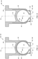
FIGS. 4-8 are sectional illustrations of the pilot chamber structure with various arrangements. -
FIG. 9 is a sectional illustration of the pilot chamber structure along a grooved surface. -
FIG. 10 is a sectional illustration of the pilot chamber structure with a non-spherical pilot chamber. -
FIGS. 11A-C are sectional illustrations depicting select steps of a method for powder injection molding the pilot chamber structure. -
FIGS. 12A and 12B are sectional illustrations depicting select steps of another method for powder injection molding the pilot chamber structure. -
FIG. 1 is a schematic illustration of apowerplant 20. Thispowerplant 20 may be configured for an aircraft. The aircraft may be an airplane, a rotorcraft, a drone (e.g., an unmanned aerial vehicle (UAV)) or any other manned or unmanned aerial vehicle and/or system. Alternatively, thepowerplant 20 be configured for a land vehicle, a water vehicle, a stationary application such as a ground-based electrical power generator, or various other mobile and/or stationary applications. However, for ease of description, thepowerplant 20 may be generally described below as an aircraft powerplant. Theaircraft powerplant 20 ofFIG. 1 includes amechanical load 22, adrivetrain 24 and an internal combustion (IC)engine 26, where thedrivetrain 24 mechanically couples themechanical load 22 to theIC engine 26. - The
mechanical load 22 may be configured as or otherwise include arotor 28 mechanically driven by theIC engine 26 through thedrivetrain 24. This drivenrotor 28 may be a bladed propulsor rotor where theaircraft powerplant 20 is configured as or otherwise includes a propulsion system for the aircraft. The propulsor rotor may be an open (e.g., un-ducted) propulsor rotor or a ducted propulsor rotor. Examples of the open propulsor rotor include a propeller rotor for a turboprop propulsion system, a rotorcraft rotor (e.g., a main helicopter rotor) for a turboshaft propulsion system, a propfan rotor for a propfan propulsion system, and a pusher fan rotor for a pusher fan propulsion system. An example of the ducted propulsor rotor is a fan rotor for a ducted fan propulsion system. The present disclosure, of course, is not limited to the foregoing exemplary propulsor rotor arrangements. Moreover, the drivenrotor 28 may alternatively be a generator rotor of an electric power generator where theaircraft powerplant 20 is (or is part of) an electrical power system for the aircraft; e.g., an auxiliary power unit (APU) for the aircraft. - The
drivetrain 24 may be configured as a direct-drive drivetrain. With such a configuration, the drivenrotor 28 is operable to rotate at a common (the same) rotational speed as anengine rotating structure 30 of theIC engine 26. Alternatively, thedrivetrain 24 may be configured as a geared drivetrain. With such a configuration, the drive rotor is operable to rotate at a different (e.g., faster or slower) rotational speed than theengine rotating structure 30. Thedrivetrain 24, for example, may include a geartrain 32 (e.g., an epicyclic gear system) and/or another transmission device coupled between the drivenrotor 28 and theengine rotating structure 30. - The
IC engine 26 may be configured as a rotary engine such as, but not limited to, a Wankel engine. TheIC engine 26 ofFIG. 2 , for example, includes anengine housing 34, anengine rotor 36, aprimary fuel injector 38 and anignition system 40. - The
engine housing 34 ofFIG. 2 includes aninternal housing cavity 42, a primaryfuel injector receptacle 44, anair intake passage 46 and a combustionproducts exhaust passage 48. Theengine housing 34 is also configured for mating with theignition system 40 as described below in further detail. Thehousing cavity 42 is formed within and enclosed by theengine housing 34. The primaryfuel injector receptacle 44 extends through aperipheral wall 50 of theengine housing 34 from anexterior 52 of theengine housing 34 to thehousing cavity 42. Theintake passage 46 extends from an inlet into theIC engine 26, through the housingperipheral wall 50, to thehousing cavity 42, which engine inlet may also be an inlet to the aircraft powerplant 20 (seeFIG. 1 ). Theexhaust passage 48 extend from thehousing cavity 42, through the housingperipheral wall 50, to an exhaust from theIC engine 26, which engine exhaust may also be an exhaust from the aircraft powerplant 20 (seeFIG. 1 ). - The
engine rotor 36 ofFIG. 2 is disposed within thehousing cavity 42, where the housingperipheral wall 50 extends circumferentially around an outer periphery of theengine rotor 36. Theengine rotor 36 is coupled to and rotatable with theengine rotating structure 30. However, theengine rotor 36 ofFIG. 2 is eccentric to theengine rotating structure 30. Acenterline 54 of theengine rotor 36, for example, is parallel with, but offset from, acenterline 56 of theengine rotating structure 30, where therotor centerline 54 is also a rotational axis of theengine rotor 36 and/or where the rotatingstructure centerline 56 is also a rotational axis of theengine rotating structure 30. With this arrangement, as theengine rotor 36 rotates about itsrotor centerline 54, therotor centerline 54 moves (e.g., circles) about the rotatingstructure centerline 56. Here, a timing gear may be provided to control a rotational velocity of theengine rotor 36 to be slower than (e.g., 1/3 of) a rotational velocity of theengine rotating structure 30. - The
engine rotor 36 may have a non-circular, lobed cross-sectional geometry when viewed, for example, in a reference plane perpendicular to therotor centerline 54. Theengine rotor 36 ofFIG. 2 , for example, includes a plurality of (e.g., arcuate, convex) peripheral rotor faces 58 arranged circumferentially about therotor centerline 54. Each circumferentially neighboring (e.g., adjacent) pair of the rotor faces 58 meets at arespective apex 60 of theengine rotor 36. Theengine rotor 36 may also include one or more rotor seals 62, where eachrotor seal 62 is arranged at (e.g., on, adjacent or proximate) a respective one of the rotor apexes 60. Eachrotor seal 62 is configured to sealingly engage (e.g., contact) and thereby form a seal interface with an interior 64 of the housingperipheral wall 50. Of course, theengine rotor 36 may be configured with various other seal elements which are omitted from the drawings for clarity. Examples of these other seal elements include, but are not limited to, gas seal element(s) and/or oil seal element(s) arranged with side faces of theengine rotor 36. - The
engine rotor 36 and theengine housing 34 may collectively form one ormore combustion volumes 66A-C (generally referred to as "66") (e.g., combustion chambers, working volumes, etc.) within theengine housing 34. Each combustion volume 66, in particular, is formed by and between a respective one of the rotor faces 58 and a corresponding (albeit changing) portion of the housingperipheral wall 50, and circumferentially between a respective neighboring pair of the rotor seals 62. Each of the combustion volumes 66 moves about thecenterline engine rotor 36 eccentrically rotates within theengine housing 34 and itshousing cavity 42. With the rotor position ofFIG. 2 , thecombustion volume 66A is fluidly coupled with the intake passage 46 (and fluidly decoupled from the exhaust passage 48), thecombustion volume 66B is fluidly coupled with the exhaust passage 48 (and fluidly decoupled from the intake passage 46), and thecombustion volume 66C is fluidly decoupled from theintake passage 46 and theexhaust passage 48. - The
primary fuel injector 38 is mated with / received within the primaryfuel injector receptacle 44. Theprimary fuel injector 38, for example, projects into the primaryfuel injector receptacle 44 and is threaded into or otherwise attached to theengine housing 34. - During engine operation, air is directed through the
intake passage 46 into a respective one of the combustion volumes 66. As theengine rotor 36 rotates within theengine housing 34, a volumetric measure of the respective combustion volume 66 decreases thereby compressing the air within that combustion volume 66. Theprimary fuel injector 38 directs (e.g., injects) primary fuel into the respective combustion volume 66 to mix with the air as it is being compressed to provide a fuel-air mixture. When the respective combustion volume 66 aligns with theignition system 40, the fuel-air mixture within that combustion volume 66 is ignited to generate combustion products. As theengine rotor 36 continues to rotate within theengine housing 34, the volumetric measure of the respective combustion volume 66 increases thereby facilitating expansion of the combustion products within the respective combustion volume 66 until those expanded combustion products are exhausted from theIC engine 26 through theexhaust passage 48. Internal combustion pressure loads of the combustion products within the respective combustion volume 66 drives rotation of theengine rotor 36 within theengine housing 34. The rotation of theengine rotor 36 and, thus, the rotation of theengine rotating structure 30 in turn drives rotation of the drivenrotor 28 ofFIG. 1 through thedrivetrain 24. - Referring to
FIG. 2 , to ignite the fuel-air mixture within one of the combustion volumes 66, theignition system 40 is configured to introduce a flame (e.g., a pilot flame) and/or relatively hot combustion products into the respective combustion volume 66. Theignition system 40 ofFIG. 2 , for example, includes a pilot chamber structure 68 (schematically shown), a pilot fuel injector 70 ("pilot injector") and a pilot ignitor 72 (e.g., a spark plug, a glow plug, etc.). Thepilot chamber structure 68 includes an internal pilot chamber 74 (e.g., a sub-chamber, a pre-ignition chamber, etc.) and a pilot aperture 76 (e.g., a transfer hole) which fluidly couples thepilot chamber 74 to the respective combustion volume 66. Thepilot injector 70 is configured to direct (e.g., inject) pilot fuel into thepilot chamber 74. Thepilot ignitor 72 is configured to ignite the pilot fuel within thepilot chamber 74 to generate the pilot flame and/or the pilot combustion products. The pilot flame and/or the pilot combustion products are directed through thepilot aperture 76 into the respective combustion volume (e.g., 66C) to ignite the fuel-air mixture within that combustion volume (e.g., 66C). - Referring to
FIG. 3 , thepilot chamber structure 68 extends longitudinally (e.g., radially relative to theaxes FIG. 2 ) along alongitudinal centerline 78 of thepilot chamber structure 68 between and to anouter end 80 of thepilot chamber structure 68 and an inner end 82 of thepilot chamber structure 68. Thepilot chamber structure 68 may be formed as a plug with a T-shaped sectional geometry. Thepilot chamber structure 68 may thereby be inserted into (e.g., plugged into) or otherwise mated with a pilotchamber structure receptacle 84 in theengine housing 34. Briefly, this pilotchamber structure receptacle 84 ofFIG. 3 projects (e.g., longitudinally along the structure centerline 78) into theengine housing 34, through the housingperipheral wall 50, from theexterior 52 of theengine housing 34 to thehousing cavity 42 and a respective one of its combustion volumes 66. Thepilot chamber structure 68 ofFIG. 3 includes a pilotchamber structure base 86 and a pilotchamber structure mount 88. - The
structure base 86 is disposed at the structure inner end 82. Thestructure base 86 ofFIG. 3 , for example, projects longitudinally along thestructure centerline 78 out from thestructure mount 88 to the structure inner end 82. Thestructure base 86 projects laterally (e.g., radially relative to the structure centerline 78) out to anexterior surface 90 of thestructure base 86. Thepilot chamber 74 is formed within thestructure base 86. Thepilot chamber 74 ofFIG. 3 has a spherical geometry which may facilitate provision of a relatively compact and durable pilot chamber structure. The present disclosure, however, is not limited to such an exemplary pilot chamber geometry. Thepilot chamber 74, for example, may alternatively have a cylindrical geometry, a frustoconical geometry, a teardrop-shaped geometry, etc. Referring again toFIG. 3 , thepilot aperture 76 projects into thestructure base 86, through aninner endwall 91 of thepilot chamber structure 68 and itsstructure base 86, from the structure inner end 82 to thepilot chamber 74. A centerline of thepilot aperture 76 may be angularly offset from thestructure centerline 78 by a non-zero acute angle. The present disclosure, however, is not limited to such an exemplary angularly offset pilot aperture arrangement. - The
pilot chamber structure 68 and itsstructure base 86 ofFIG. 3 also include afuel aperture 92 and at least oneignitor aperture 94. Thefuel aperture 92 and theignitor aperture 94 each project laterally into thestructure base 86, through anannular sidewall 95 of thepilot chamber structure 68 and itsstructure base 86, from the baseexterior surface 90 to aninterior surface 97 of thestructure base 86, which base internal surface 97 (e.g., completely) forms an outer peripheral boundary of thepilot chamber 74 within thepilot chamber structure 68. Thefuel aperture 92 and theignitor aperture 94 ofFIG. 3 are arranged to opposing lateral sides of thepilot chamber 74. The present disclosure, however, is not limited to such an exemplary arrangement. - The structure mount 88 is disposed at the structure
outer end 80. The structure mount 88 ofFIG. 3 , for example, projects longitudinally along thestructure centerline 78 out from thestructure base 86 to the structureouter end 80. The structure mount 88 also projects laterally out from thestructure base 86 and itsbase exterior surface 90 to a (e.g., annular) lateraldistal end 96 of thestructure mount 88. With this arrangement, the structure mount 88 forms a (e.g., annular) shelf 98 (e.g., an axial seal face) which projects laterally inward from the mountdistal end 96 towards the baseexterior surface 90. Thisshelf 98 may be abutted against or otherwise engaged with a (e.g., annular)shelf 100 of theengine housing 34 along the pilotchamber structure receptacle 84. - The
pilot chamber structure 68 ofFIG. 3 is configured as amonolithic body 102. Thismonolithic body 102 may be constructed from a continuous mass of material; e.g., a single material or a combination of multiple materials. Thepilot chamber structure 68, for example, may be additively manufactured, powder injection molded (PIM) and/or otherwise formed as a single, unitary body, examples of which are described below in further detail. By contrast, a non-monolithic body may be formed from a plurality of discretely formed bodies, which bodies are joined (e.g., mechanically, welded, etc.) together subsequent to (e.g., complete) formation thereof to form a multi-segment structure. With the monolithic configuration ofFIG. 3 , the baseinterior surface 97 may be substantially or completely uninterrupted; e.g., besides respective openings to pilotaperture 76, thefuel aperture 92 and theignitor aperture 94. By contrast, where a pilot chamber structure is formed as a multi-segment structure (e.g., a structure formed by welding two conventionally machined metal parts together at a mid-plane of an internal pilot chamber), a seam line may interrupt an interior surface forming its pilot chamber. Such a seam line may disrupt flow dynamics within the pilot chamber. Moreover, a seam between segments of a multi-segment structure may form a structural weak point under certain conditions and/or additional material (e.g., weld spatter) may be solidified within the pilot chamber beyond the intended joint line. - In some embodiments, referring to
FIGS. 4 and 5 , thepilot chamber structure 68 may be configured with aninternal cavity 104. Thisinternal cavity 104 may extend circumferentially about thepilot chamber 74 and/or thepilot aperture 76 to provide a thermal buffer thereabout. Theinternal cavity 104, for example, may extend circumferentially about (e.g., partially or completely around) thestructure centerline 78 and/or areference line 106 perpendicular to the structure centerline 78 (e.g., extending out of a plane ofFIG. 4, 5 ). Theinternal cavity 104 ofFIGS. 4 and 5 is disposed in thestructure sidewall 95 between the baseinterior surface 97 and the baseexterior surface 90. Theinternal cavity 104 ofFIGS. 4 and 5 is disposed in thestructure endwall 91 between the baseinterior surface 97 and a distal end surface 108 of thepilot chamber structure 68 at the structure inner end 82. Referring toFIG. 4 , theinternal cavity 104 may extend laterally across thepilot chamber structure 68 through abackwall 110 of thepilot chamber structure 68 adjacent thepilot chamber 74. Alternatively, referring toFIG. 5 , an (e.g., arcuate or annular) end of theinternal cavity 104 may extend longitudinally along thestructure centerline 78 in a direction away from thepilot chamber 74 and thepilot aperture 76 towards the structureouter end 80. While theinternal cavity 104 is shown inFIGS. 4 and 5 as an air cavity, it is contemplated theinternal cavity 104 may alternatively be partially or completely filled with a thermal barrier material; e.g., a refractory metal. - In some embodiments, referring to
FIGS. 6 and 7 , one or more material properties of thepilot chamber structure 68 and itsmonolithic body 102 may change (e.g., may continuously or incrementally vary) as thepilot chamber structure 68 projects out / away from the baseinterior surface 97; e.g., laterally between baseinterior surface 97 and the baseexterior surface 90. Examples of such material properties include, but are not limited to, a material makeup (e.g., a chemical composition) of thepilot chamber structure 68 and itsmonolithic body 102, and a material density of thepilot chamber structure 68 and itsmonolithic body 102. - Referring to
FIG. 6 , thepilot chamber structure 68 may be constructed from multiple materials. For example, aninterior portion 112 of thepilot chamber structure 68 and itsmonolithic body 102 at least partially or completely forming the baseinterior surface 97 may be formed (e.g., only or substantially) from a first material. Anexterior portion 114 of thepilot chamber structure 68 and itsmonolithic body 102 at least partially or completely forming the baseexterior surface 90 may be formed (e.g., only or substantially) from a second material which is different than the first material. An optionalintermediate portion 116 of thepilot chamber structure 68 and itsmonolithic body 102 between theinterior portion 112 and theexterior portion 114 may be formed from a mixture (e.g., a gradient) of the first material and the second material. With such a construction, the first and the second materials may be selected based on their location within thepilot chamber structure 68. For example, the first material may be selected for increased temperature and/or oxidation resistance. The second material may be selected for increased fracture toughness and/or fatigue resistance. Here, theinterior portion 112 may provide a shell around thepilot chamber 74. - In some embodiments, the first and the second materials may be the same type of material. For example, both the first and the second materials may be ceramics. In another example, both the first and the second materials may be metals; e.g., pure metals and/or alloys. However, a chemical composition of the first material (the first ceramic or the first metal) is different than a chemical composition of the second material (the second ceramic or the second metal). In other embodiments, the first and the second materials may be different types of material. For example, the first material may be a ceramic and the second material may be a metal, or vice versa. Moreover, while the
pilot chamber structure 68 is described above as being constructed from two different materials - the first and the second materials and a blend thereof - it is contemplated thepilot chamber structure 68 may alternatively be constructed from three or more different materials. - Referring to
FIG. 7 , thepilot chamber structure 68 may be formed with multiple densities. For example, aninterior portion 118 of thepilot chamber structure 68 and itsmonolithic body 102 at least partially or completely forming the baseinterior surface 97 may be formed with a first density. Anexterior portion 120 of thepilot chamber structure 68 and itsmonolithic body 102 at least partially or completely forming the baseexterior surface 90 may be formed with a second density which is different (e.g., more or less) than the first density. An optionalintermediate portion 122 of thepilot chamber structure 68 and itsmonolithic body 102 may be formed to provide a density gradient between the first density of theinterior portion 118 and the second density of theexterior portion 120. With such a construction, the first and the second densities may be selected based on their location within thepilot chamber structure 68. The change in density may be provided by changing materials as described above with respect toFIG. 6 . The change in density may also or alternatively be provided using other techniques; e.g., different material deposition and/or material compaction techniques, heat treating, etc. - In some embodiments, referring to
FIG. 8 , surfaces of thepilot chamber structure 68 may be provided with different surface roughnesses by providing, for example, tailored surface texturing. A surface roughness of part or all of the baseinterior surface 97, for example, may be different (e.g., greater or less) than a surface roughness of part or all of the baseexterior surface 90. By varying the surface roughness, flow dynamics and/or heat exchanger characteristics along that surface (e.g., 90, 97) may be tailored. For example, the surface roughness of the baseinterior surface 97 may be tailored (e.g., increased) to promote boundary layer turbulence within thepilot chamber 74 and/or cooling efficiency. Referring toFIG. 9 , one or more of thesurfaces more channels 124,ribs 126 and/or various other heat exchanger features. Here, eachchannel 124 projects into thepilot chamber structure 68 from therespective surface - In some embodiments, referring to
FIGS. 3-8 , at least a portion or an entirety of the baseinterior surface 97 may be configured with a uniform (e.g., constant) radius of curvature 128 (seeFIG. 3 ). For example, the baseinterior surface 97 and thepilot chamber 74 bounded thereby may be configured with spherical geometries. In other embodiments, referring toFIG. 10 , at least a portion or an entirety of the baseinterior surface 97 may be configured with a non-uniform (e.g., variable, changing, etc.) radius of curvature 128'. For example, the baseinterior surface 97 and thepilot chamber 74 bounded thereby may be configured with teardrop-shaped geometries. In another example, the baseinterior surface 97 and thepilot chamber 74 bounded thereby may be configured with conical or frustoconical geometries. The present disclosure, however, is not limited to the foregoing exemplary arrangements. - As described above, the
pilot chamber structure 68 may be constructed from a single material or multiple materials; e.g., metal(s) and/or ceramic(s). Examples of the metal include, but are not limited to, a nickel (Ni) alloy or a cobalt (Co) alloy, or the like. Examples of the ceramic include, but are not limited to, silicon carbide (SiC) or silicon nitride (SiN), or the like. The present disclosure, however, is not limited to the foregoing exemplary materials. - In some embodiments, referring to
FIG. 3 , thepilot chamber structure 68 may be configured for installation with and/or removal from theIC engine 26 and its engine housing 34 (e.g., completely) from an exterior of theIC engine 26 and itsengine housing 34. Thus, assembly and/or maintenance personnel may not need access to an interior of theIC engine 26 and itsengine housing 34 for pilot chamber structure installation, inspection and/or removal. Removing thepilot chamber structure 68 may also facilitate inspection of one or more elements internal to theIC engine 26; e.g., therotor seal 62 ofFIG. 2 , theinterior 64 of the housingperipheral wall 50 ofFIG. 2 , the rotor faces 58 ofFIG. 2 , etc. This may simplify engine assembly, inspection and/or maintenance. - The
ignition system 40 is described above with reference to the rotary engine; e.g., the Wankel engine. It is contemplated, however, theignition system 40 may alternatively be configured with various other types of engines such as a reciprocating piston engine or a gas turbine engine. The present disclosure therefore is not limited to any particular engine types or configurations. - In some embodiments, the
pilot chamber structure 68 may be formed using additively manufacturing; e.g., 3D printing. For example, a monolithic green structure (e.g., a green part preform of the pilot chamber structure 68) may be built up in a layer-by-layer fashion. Here, the term "green" may describe a structure formed by a mass of (e.g., densely packed) powder embedded within and held together by a solidified binder. This structure may (or may not) also include reinforcement material (e.g., particles, fibers, etc.) intermixed with the powder and embedded in the solidified binder, which reinforcement material may (or may not) be composed of a different material than the powder. Examples of the powder include, but are not limited to, metal powder and/or ceramic powder. Examples of the binder include, but are not limited to, wax, ethylene vinyl acetate (EVA), epoxy, polyethylene and polypropylene. Examples of the reinforcement material include, but are not limited to, carbon fiber whiskers, SiC particulates and/or oxide particles. The term "preform" may describe a structure which shares a substantially common (e.g., the same) configuration with the structure to be formed. The green structure, for example, may have the same geometry, features, etc. as thepilot chamber structure 68. However, the green structure may be slightly bigger than thepilot chamber structure 68 where shrinkage is expected during the formation process (e.g., final sintering process). Examples of suitable additive manufacturing techniques include, but are not limited to, binder jetting, stereolithography, fused deposition modeling (FDM), metal extrusion (MEX), and bound deposition molding (BDM). - Following the additive manufacturing of the green structure, the green structure may be debound to partially or substantially remove the binder. For example, during thermal debinding, the green structure may be imbedded in a compacted powder bed of another material and heated in a protective atmosphere to extract the binder while maintaining (e.g., keeping) an overall shape of the structure. Other examples of debinding include, but are not limited to, solvent debinding and catalytic debinding (e.g., using a vapor of a solvent to remove the binder). The debinding produces a brown structure; e.g., a brown part preform of the
pilot chamber structure 68. Here, the term "brown" may describe a porous and/or friable structure substantially formed by the mass of the powder (and the reinforcement material when included). While the brown structure is substantially devoid of the binder, it is contemplated a residual amount of the binder may be retained to help hold the brown structure together prior to sintering. The brown structure may then be sintered to form thepilot chamber structure 68. Of course, one or more additional processes may also be performed to strengthen and/or finish thepilot chamber structure 68. One or more features of thepilot chamber structure 68 may be machined, the sintered material may be impregnated and/or infiltrated with another material, one or more surfaces of thepilot chamber structure 68 may be coated, thepilot chamber structure 68 may be heat treated, or the like. The present disclosure, however, is not limited to the foregoing exemplary processes. For example, the additive manufacturing may alternatively be performed using a technique which does not require debinding, etc. - In some embodiments, the
pilot chamber structure 68 may be formed using powder injection molding (PIM). For example, referring toFIG. 11A , multiplegreen components pilot chamber structure 68. Similar to the green structure described above, each green component 130 includes a mass of the powder (and optionally the reinforcement material) embedded within and held together by the solidified binder. Referring toFIG. 11B , the green components 130 are arranged together in intimate contact (with or without a linkage between the green components 130) to form agreen structure 132 / a green assembly. Referring toFIG. 11C , thegreen structure 132 is then co-debound to provide a monolithicbrown structure 134. During this co-debinding, the interconnectedgreen structure 132 may be placed under shape retaining conditions, and the binder may be melted to form a seamless monolithic green structure. This seamless monolithic green structure is then debound to substantially remove the binder and provide thebrown structure 134. Another example of the co-debinding is discloses inU.S. Patent No. 10,226,818 brown structure 134 may then be sintered to form thepilot chamber structure 68; e.g., seeFIGS. 3-8 and10 . Of course, one or more additional processes may also be performed to strengthen and/or finish thepilot chamber structure 68. One or more features of thepilot chamber structure 68 may be machined, the sintered material may be impregnated and/or infiltrated with another material, one or more surfaces of thepilot chamber structure 68 may be coated, thepilot chamber structure 68 may be heat treated, or the like. - In some embodiments, referring to
FIG. 12A , the powder injection molding may alternatively be performed to form a monolithic green structure 136 (e.g., the green part preform of the pilot chamber structure 68) rather than multiple green components 130 as described above. A preform of thepilot chamber 74 may be formed within thegreen structure 136 utilizing asoluble core 138. Referring toFIG. 12B , following the formation of thegreen structure 136, thesoluble core 138 may be removed to leave behind an empty cavity 140 - the preform of thepilot chamber 74. Thesoluble core 138 may be removed using a hot bath, induction heating and/or various other techniques. Thegreen structure 136 may subsequently be processed as described above (e.g., debound and sintered) to form thepilot chamber structure 68. - While various embodiments of the present disclosure have been described, it will be apparent to those of ordinary skill in the art that many more embodiments and implementations are possible within the scope of the disclosure. For example, the present disclosure as described herein includes several aspects and embodiments that include particular features. Although these features may be described individually, it is within the scope of the present disclosure that some or all of these features may be combined with any one of the aspects and remain within the scope of the disclosure. Accordingly, the present disclosure is not to be restricted except in light of the attached claims and their equivalents.
Claims (15)
- An apparatus for a powerplant (20), the apparatus comprising a pilot chamber structure (68) formed as a monolithic body (102), the pilot chamber structure (68) including:an exterior surface (90);an interior surface (97);a pilot chamber (74);a pilot aperture (76);a fuel aperture (92); andan ignitor aperture (94), wherein:a material property of the monolithic body (102) varies as the pilot chamber structure (68) extends between the exterior surface (90) and the interior surface (97);the interior surface (97) forms an outer peripheral boundary of the pilot chamber (74);the pilot chamber (74) is internal to the pilot chamber structure (68);the pilot aperture (76) projects into the pilot chamber structure (68) to the pilot chamber (74);the fuel aperture (92) projects into the pilot chamber structure (68) to the pilot chamber (74); andthe ignitor aperture (94) projects into the pilot chamber structure (68) to the pilot chamber (74).
- The apparatus of claim 1, wherein the material property comprises a density of the monolithic body (102).
- The apparatus of claim 2, wherein:an interior portion (112; 118) of the monolithic body (102), that at least partially forms the interior surface (97), has a higher density than an exterior portion (114; 120) of the monolithic body (102), that at least partially forms the exterior surface (90); oran interior portion (112;118) of the monolithic body (102), that at least partially forms the interior surface (97), has a lower density than an exterior portion (114;120) of the monolithic body (102), that at least partially forms the exterior surface (90).
- The apparatus of any preceding claim, wherein the material property comprises a material composition of the monolithic body (102).
- The apparatus of claim 4, wherein:an or the interior portion (112;118) of the monolithic body (102), that at least partially forms the interior surface (97). comprises a first material; andan or the exterior portion (114;120) of the monolithic body (102), that at least partially forms the exterior surface (90), comprises a second material which is different than the first material,optionally wherein an intermediate portion (116;122) of the monolithic body (102) between the interior portion (112;118) and the exterior portion (114;120) comprises the first material and the second material.
- The apparatus of any preceding claim, wherein a surface roughness of the interior surface (97) is different than a surface roughness of the exterior surface (90).
- The apparatus of any preceding claim, wherein a channel (124) projects into the pilot chamber structure (68) from the interior surface (97).
- The apparatus of any preceding claim, wherein:at least a portion of the interior surface (97) has a uniform radius of curvature (128); and/orat least a portion of the interior surface (97) has a non-uniform radius of curvature (128').
- The apparatus of any preceding claim, wherein the monolithic body (102) comprises a ceramic and/or a metal.
- The apparatus of any preceding claim, further comprising:a housing (34) forming a combustion volume (66A,66B,66C) within the housing (34);a primary fuel injector (38) configured to inject primary fuel into the combustion volume (66A,66B,66C); andan ignition system (40) configured to ignite the primary fuel within the combustion volume (66A,66B,66C), the ignition system (40) including a pilot fuel injector (70), a pilot ignitor (72) and the pilot chamber structure (68), wherein:the pilot fuel injector (70) is mated with the fuel aperture (92) and configured to inject pilot fuel into the pilot chamber (74);the pilot ignitor (72) is mated with the ignitor aperture (94) and configured to ignite the pilot fuel within the pilot chamber (74); andthe pilot chamber (74) is fluidly coupled with the combustion volume (66A,66B,66C) through the pilot aperture (76).
- An apparatus for a powerplant (20), the apparatus comprising:a pilot chamber structure (68) formed as a monolithic body (102), the pilot chamber (68) structure including an exterior surface (90), an interior surface (97), a pilot chamber (74), a pilot aperture (76), a fuel aperture (92) and an ignitor aperture (94);the interior surface (97) forming an outer peripheral boundary of the pilot chamber (74), and a surface texture of the interior surface (97) different than a surface texture of the exterior surface (90);the pilot chamber (74) internal to the pilot chamber structure (68);the pilot aperture (76) projecting into the pilot chamber structure (68) to the pilot chamber (74);the fuel aperture (92) projecting into the pilot chamber structure (68) to the pilot chamber (74); andthe ignitor aperture (94) projecting into the pilot chamber structure (68) to the pilot chamber (74).
- The apparatus of any preceding claim, wherein:the pilot chamber structure (68) further includes an internal cavity (104) between the interior surface (97) and the exterior surface (90); andthe internal cavity (104) extends circumferentially about the pilot chamber (74).
- A method of manufacture, comprising forming a pilot chamber structure (68) as a monolithic body (102), the forming of the pilot chamber structure (68) including:forming a green structure (132; 136) using powder injection molding;debinding the green structure (132; 136) to form a monolithic brown structure (134); andsintering the monolithic brown structure (134), the pilot chamber structure (68) including a pilot chamber (74), a pilot aperture (76), a fuel aperture (92) and an ignitor aperture (94), the pilot chamber (74) internal to the pilot chamber structure (68), the pilot aperture (76) projecting into the pilot chamber structure (68) to the pilot chamber (74), the fuel aperture (92) projecting into the pilot chamber structure (68) to the pilot chamber (74), and the ignitor aperture (74) projecting into the pilot chamber structure (68) to the pilot chamber (74).
- The method of claim 13, wherein the green structure (136) comprises a monolithic green body (136) configured as a preform of the pilot chamber structure (68),
optionally wherein the method further comprises removing a soluble core (138) from a preform of the pilot chamber (74) within the monolithic green body (136), the preform of the pilot chamber (74) formed in the green structure (136) during the powder injection molding using the soluble core (138). - The method of claim 13, wherein:the green structure (132) includes a first green part (130A) and a second green part (130B); andthe debinding of the green structure (132) comprises co-debinding the first green part (130A) with the second green part (130B) to form the monolithic brown structure (134).
Applications Claiming Priority (1)
| Application Number | Priority Date | Filing Date | Title |
|---|---|---|---|
| US18/242,334 US12163462B1 (en) | 2023-09-05 | 2023-09-05 | Internal combustion engine with monolithic pilot chamber structure |
Publications (1)
| Publication Number | Publication Date |
|---|---|
| EP4520932A1 true EP4520932A1 (en) | 2025-03-12 |
Family
ID=92708846
Family Applications (1)
| Application Number | Title | Priority Date | Filing Date |
|---|---|---|---|
| EP24198764.3A Pending EP4520932A1 (en) | 2023-09-05 | 2024-09-05 | Internal combustion engine with monolithic pilot chamber structure |
Country Status (3)
| Country | Link |
|---|---|
| US (3) | US12163462B1 (en) |
| EP (1) | EP4520932A1 (en) |
| CA (1) | CA3253831A1 (en) |
Families Citing this family (1)
| Publication number | Priority date | Publication date | Assignee | Title |
|---|---|---|---|---|
| US12163462B1 (en) * | 2023-09-05 | 2024-12-10 | Pratt & Whitney Canada Corp. | Internal combustion engine with monolithic pilot chamber structure |
Citations (6)
| Publication number | Priority date | Publication date | Assignee | Title |
|---|---|---|---|---|
| US4522171A (en) * | 1982-06-18 | 1985-06-11 | Feldmuhle Aktiengesellschaft | Pre-combustion or turbulence chamber for internal combustion engines |
| US4834042A (en) * | 1987-06-06 | 1989-05-30 | Ngk Insulators, Ltd. | Ceramic precombustion chamber for internal combustion engine |
| JPH01267312A (en) * | 1988-04-19 | 1989-10-25 | Mazda Motor Corp | Manufacture of heating type whirl chamber |
| US5014664A (en) * | 1989-07-27 | 1991-05-14 | Isuzu Motors Limited | Heat-insulating structure of swirl chamber |
| EP0412659B1 (en) * | 1989-08-10 | 1993-09-29 | Isuzu Motors Limited | Heat-insulating structure of swirl chamber and production method thereof |
| US10226818B2 (en) | 2009-03-20 | 2019-03-12 | Pratt & Whitney Canada Corp. | Process for joining powder injection molded parts |
Family Cites Families (18)
| Publication number | Priority date | Publication date | Assignee | Title |
|---|---|---|---|---|
| US3909897A (en) * | 1971-06-07 | 1975-10-07 | Volvo Penta Ab | Method for making a rotary piston internal combustion engine |
| US3918137A (en) * | 1973-07-05 | 1975-11-11 | Ford Motor Co | Wear-resistant coating for rotary engine side housing and method of making |
| US3888746A (en) * | 1974-01-04 | 1975-06-10 | Ford Motor Co | Method of providing an intermediate steel layer for chrome plating on rotor housings |
| JPS6193227A (en) | 1984-10-11 | 1986-05-12 | Mazda Motor Corp | Manufacturing method of engine subchamber |
| JPH0223788Y2 (en) | 1984-10-17 | 1990-06-28 | ||
| US5715787A (en) | 1995-10-31 | 1998-02-10 | Isuzu Ceramics Research Institute Co., Ltd | Internal-combustion engine having a pre-combustion chamber |
| US5915351A (en) | 1997-02-24 | 1999-06-29 | Chrysler Corporation | Insulated precombustion chamber |
| US6913210B2 (en) * | 2001-09-28 | 2005-07-05 | Holley Performance Products | Fuel injector nozzle adapter |
| US12163462B1 (en) * | 2023-09-05 | 2024-12-10 | Pratt & Whitney Canada Corp. | Internal combustion engine with monolithic pilot chamber structure |
| US9038594B2 (en) | 2011-07-28 | 2015-05-26 | Pratt & Whitney Canada Corp. | Rotary internal combustion engine with pilot subchamber |
| US10557407B2 (en) * | 2011-07-28 | 2020-02-11 | Pratt & Whitney Canada Corp. | Rotary internal combustion engine with pilot subchamber |
| EP3181854A1 (en) | 2015-12-14 | 2017-06-21 | Caterpillar Energy Solutions GmbH | Pre-chamber of internal combustion engine |
| US10041402B2 (en) | 2016-05-12 | 2018-08-07 | Pratt & Whitney Canada Corp. | Internal combustion engine with split pilot injection |
| US10815877B2 (en) * | 2017-01-18 | 2020-10-27 | Pratt & Whitney Canada Corp. | Method of operating a rotary engine |
| US10343214B2 (en) | 2017-02-17 | 2019-07-09 | General Electric Company | Method for channel formation in binder jet printing |
| EP3620628A1 (en) | 2018-09-04 | 2020-03-11 | Winterthur Gas & Diesel Ltd. | Pre-chamber |
| US11686242B2 (en) | 2019-04-29 | 2023-06-27 | Siemens Energy, Inc. | Pre-combustion chamber system |
| US11111848B1 (en) * | 2020-06-02 | 2021-09-07 | Pratt & Whitney Canada Corp. | Fuel injection system for aircraft engine |
-
2023
- 2023-09-05 US US18/242,334 patent/US12163462B1/en active Active
-
2024
- 2024-08-30 CA CA3253831A patent/CA3253831A1/en active Pending
- 2024-09-05 EP EP24198764.3A patent/EP4520932A1/en active Pending
- 2024-12-09 US US18/973,948 patent/US20250101907A1/en active Pending
-
2025
- 2025-01-28 US US19/039,196 patent/US20250305444A1/en active Pending
Patent Citations (6)
| Publication number | Priority date | Publication date | Assignee | Title |
|---|---|---|---|---|
| US4522171A (en) * | 1982-06-18 | 1985-06-11 | Feldmuhle Aktiengesellschaft | Pre-combustion or turbulence chamber for internal combustion engines |
| US4834042A (en) * | 1987-06-06 | 1989-05-30 | Ngk Insulators, Ltd. | Ceramic precombustion chamber for internal combustion engine |
| JPH01267312A (en) * | 1988-04-19 | 1989-10-25 | Mazda Motor Corp | Manufacture of heating type whirl chamber |
| US5014664A (en) * | 1989-07-27 | 1991-05-14 | Isuzu Motors Limited | Heat-insulating structure of swirl chamber |
| EP0412659B1 (en) * | 1989-08-10 | 1993-09-29 | Isuzu Motors Limited | Heat-insulating structure of swirl chamber and production method thereof |
| US10226818B2 (en) | 2009-03-20 | 2019-03-12 | Pratt & Whitney Canada Corp. | Process for joining powder injection molded parts |
Also Published As
| Publication number | Publication date |
|---|---|
| CA3253831A1 (en) | 2025-06-03 |
| US20250305444A1 (en) | 2025-10-02 |
| US20250101907A1 (en) | 2025-03-27 |
| US12163462B1 (en) | 2024-12-10 |
Similar Documents
| Publication | Publication Date | Title |
|---|---|---|
| CN105525993B (en) | heat exchanger components | |
| EP2971684B1 (en) | Hollow-wall heat shield for fuel injector component | |
| EP2759772A1 (en) | Combustors with complex shaped effusion holes | |
| US10823061B2 (en) | Engine air inlet having a double-panel heated wall | |
| US20250101907A1 (en) | Internal combustion engine with monolithic pilot chamber structure | |
| US10247106B2 (en) | Method and system for rotating air seal with integral flexible heat shield | |
| EP2017534A1 (en) | Components capable of transporting liquids manufactured using injection molding | |
| EP3919248B1 (en) | Multi-piece mandrel for cmc components | |
| EP2989296A1 (en) | Internally damped airfoiled component and method | |
| EP2018917A1 (en) | Injection molding methods for manufacturing components capable of transporting liquids | |
| US20230383659A1 (en) | System and method for repairing high-temperature gas turbine components | |
| EP3284916A1 (en) | A component for a gas turbine engine and method of manufacture | |
| EP2064435A2 (en) | Open cycle internal combustion engine | |
| CA2588626A1 (en) | A process for producing static components for a gas turbine engine | |
| US10137499B2 (en) | Method and assembly for forming components having an internal passage defined therein | |
| GB2539092A (en) | Manufacture of component with cavity | |
| EP3238860A1 (en) | Method and assembly for forming components using a jacketed core | |
| GB2590124A (en) | Casing integrated fluid distribution system | |
| WO2017042448A1 (en) | Casing for rotary machines and in particular for turbomachines | |
| EP3181265A1 (en) | Method and assembly for forming components having internal passages using a lattice structure | |
| EP4502351A2 (en) | Internal combustion engine with coated ignition system component(s) | |
| EP4450784B1 (en) | Internal combustion engine with ceramic pilot chamber component(s) | |
| EP4187191B1 (en) | Composite powder for additive manufacturing, method for manufacturing composite powder | |
| US20210363897A1 (en) | Thermal insulation features for gas turbine engines | |
| CN118997924A (en) | Air turbine starter with containment assembly |
Legal Events
| Date | Code | Title | Description |
|---|---|---|---|
| PUAI | Public reference made under article 153(3) epc to a published international application that has entered the european phase |
Free format text: ORIGINAL CODE: 0009012 |
|
| STAA | Information on the status of an ep patent application or granted ep patent |
Free format text: STATUS: THE APPLICATION HAS BEEN PUBLISHED |
|
| AK | Designated contracting states |
Kind code of ref document: A1 Designated state(s): AL AT BE BG CH CY CZ DE DK EE ES FI FR GB GR HR HU IE IS IT LI LT LU LV MC ME MK MT NL NO PL PT RO RS SE SI SK SM TR |
|
| STAA | Information on the status of an ep patent application or granted ep patent |
Free format text: STATUS: REQUEST FOR EXAMINATION WAS MADE |
|
| 17P | Request for examination filed |
Effective date: 20250912 |