EP4520885A1 - Water distributor - Google Patents
Water distributor Download PDFInfo
- Publication number
- EP4520885A1 EP4520885A1 EP23195478.5A EP23195478A EP4520885A1 EP 4520885 A1 EP4520885 A1 EP 4520885A1 EP 23195478 A EP23195478 A EP 23195478A EP 4520885 A1 EP4520885 A1 EP 4520885A1
- Authority
- EP
- European Patent Office
- Prior art keywords
- water
- insert element
- water distributor
- disc
- outlet section
- Prior art date
- Legal status (The legal status is an assumption and is not a legal conclusion. Google has not performed a legal analysis and makes no representation as to the accuracy of the status listed.)
- Pending
Links
Images




Classifications
-
- E—FIXED CONSTRUCTIONS
- E03—WATER SUPPLY; SEWERAGE
- E03D—WATER-CLOSETS OR URINALS WITH FLUSHING DEVICES; FLUSHING VALVES THEREFOR
- E03D11/00—Other component parts of water-closets, e.g. noise-reducing means in the flushing system, flushing pipes mounted in the bowl, seals for the bowl outlet, devices preventing overflow of the bowl contents; devices forming a water seal in the bowl after flushing, devices eliminating obstructions in the bowl outlet or preventing backflow of water and excrements from the waterpipe
- E03D11/13—Parts or details of bowls; Special adaptations of pipe joints or couplings for use with bowls, e.g. provisions in bowl construction preventing backflow of waste-water from the bowl in the flushing pipe or cistern, provisions for a secondary flushing, for noise-reducing
- E03D11/17—Means for connecting the bowl to the flushing pipe
-
- E—FIXED CONSTRUCTIONS
- E03—WATER SUPPLY; SEWERAGE
- E03D—WATER-CLOSETS OR URINALS WITH FLUSHING DEVICES; FLUSHING VALVES THEREFOR
- E03D2201/00—Details and methods of use for water closets and urinals not otherwise provided for
- E03D2201/40—Devices for distribution of flush water inside the bowl
Definitions
- the present disclosure relates to a water distributor for a urinal or WC.
- Urinals and WCs comprise a flushing system to flush the bowl after use.
- This volume is the residual volume which is often as large as 100 ml and the "post-flush” (also referred to as “after-flow”) can sometimes last as long as between 20 to 40 seconds.
- This "post-flush” is unwanted since it can lead to discolouring in the area of the bowl where the water enters. Further, it can lead to an increased lime-scaling of the bowl and associated components.
- EP4015720A1 discloses a bathroom fitting comprising an insert element which can be removed from a water guide pipe for removing lime scale deposits from the insert element. While this solution provides efficient cleaning and thereby improved flushing operation, a solution that actually reduces the lime-scaling would be advantageous.
- the above object is achieved by a water distributor.
- the water distributor comprises a connector configured to be mounted to an associated sanitary equipment, said connector comprising an inlet section configured to receive water from a water supply, and an outlet section configured to discharge water into the associated sanitary equipment.
- the water distributor further comprises an insert element configured to be removably inserted into the outlet section and forming a baffle for water flowing into the outlet section.
- the insert element comprises a check valve.
- the check valve may comprise a disc being moveable between a closed position and an open position, and wherein in the closed position, the disc closes the inlet section of the connector.
- the disc may be arranged inside of a flange of the insert element. This ensures proper sealing of the check valve without any specific requirements on other components than the insert element.
- the disc may be connected to a piston being supported by a piston holder of the insert element.
- the piston holder will assist in providing a smooth and accurate motion of the disc, preventing any misalignment which may affect the sealing negatively.
- the check valve may be configured to bias the disc towards its closed position, preferably the check valve comprises a spring arranged to bias the disc towards its closed position. Undesired escape of water is thereby prevented, as the check valve is always closed unless there is a sufficient water pressure acting on it.
- the spring may have a spring constant being selected so that the check valve opens by the pressure of the incoming water from the water supply. Hence it is possible to design the water distributor according to various water pressures by only adjusting the spring.
- the spring may be a conical or a cylindrical compression spring.
- a conical spring will assist in ensuring a correct motion and positioning of the disc.
- the disc may comprise a sealing. This improves operation of the water distributor and reduces the risk for water leakage.
- the sealing may substantially cover the outer rim and/or edge of the disc. Hence, the sealing action is made even better, as the outer rim and/or edge is in a sealed engagement when the check valve is closed.
- the insert element may have a longitudinal axis extending in parallel with the insertion direction into the outlet section, and a transverse axis extending in parallel with the width direction of the outlet section and perpendicular to the longitudinal axis, wherein the insert element comprises at least one water channel extending non-parallel with each one of the longitudinal axis and the transverse axis. This allows the water to spread across the bowl of the sanitary equipment thereby improving the flushing action. Further, by designing the water channels with respect to specific bowls, the flushing action may be optimized.
- the insert element may comprise a plurality of water channels configured to discharge water at different directions. This further improves the flushing action, providing an advantageous cleaning effect.
- the insert element may comprise a snap-lock configured to secure the insert element to the connector. This not only facilitates mounting, but it also prevents improper mounting as well as it ensures a robust connection of the insert element.
- a water distributor comprising a connector configured to be mounted to an associated sanitary equipment, said connector comprising an inlet section configured to receive water from a water supply, and an outlet section configured to discharge water into the associated sanitary equipment.
- the water distributor further comprises an insert element configured to be removably inserted into the outlet section and forming a baffle for water flowing into the outlet section.
- the insert element has a longitudinal axis extending in parallel with the insertion direction into the outlet section, and a transverse axis extending in parallel with the width direction of the outlet section and perpendicular to the longitudinal axis, wherein the insert element comprises at least one water channel extending non-parallel with each one of the longitudinal axis and the transverse axis.
- an insert element is provided.
- the insert element is configured to form part of the water distributor according to the first or second aspect.
- a sanitary equipment such as a urinal or a WC.
- the sanitary equipment comprises a water distributor according to the first or second aspect.
- the present disclosure relates to a water distributor 1 configured to distribute water, coming from a water supply, into a sanitary equipment 50 such as a urinal or a WC.
- sanitary equipment 50 is not limited to these examples, but other types of sanitary equipment 50 comprise e.g. bidets, sinks, bathtubs, etc.
- Operation of the water distributor 1 may be controlled by activating a flushing action, or in case of other types of sanitary equipment 50 the water distributor 1 may operate to discharge water into a bathtub or similar devices.
- the water distributor 1 comprises a connector 10 and an insert element 20.
- the insert element 20 can be removed from the connector 10 for cleaning and removal of lime-scale that has built-up during use.
- the insert 20 may in some examples be configured to divert the discharged water in different directions along the inside of the sanitary equipment 50, thereby ensuring sufficient cleaning after it has been used by a person.
- Sanitary equipment 50 is shown in Fig. 1 , here represented by a urinal. Flushing of the urinal 50 is accomplished by water being allowed to flow into the bowl 52 via a water distributor 1.
- the water distributor 1 is arranged at the top of the urinal 50 such that flushing water may spread across the bowl 52 thereby providing a cleaning action of at least the majority of the bowl 52.
- the water distributor 1 is arranged inside the bowl 52, and it is connected to upstream water piping 100 extending through the bowl 52.
- a water inlet valve (not shown) is normally arranged in connection with the piping 100, and one or more controllers (not shown) may be connected to the water inlet valve in order to control actuation and specific parameters of the flushing action.
- Fig. 2 details of the water distributor 1 are further shown in cross-section.
- the water distributor 1 is connected to the sanitary equipment 50 and to the upstream piping 100 as already explained with reference to Fig. 1 .
- the water distributor 1 comprises a connector 10 and an insert element 20.
- the connector 10 has two main purposes; to allow connection to the upstream piping 100, and to form a holder for the insert element 20.
- water will flow from the upstream piping 100 and through the connector 10 into the sanitary equipment 50.
- the insert element 20 will assist in diverting the water into the sanitary equipment 50.
- the insert element 20 will also assist in reducing lime-scaling by preventing the post-flush problem described in the background section.
- the sanitary equipment 50 comprises a rear wall 54.
- a through hole 56 is provided at the rear wall 54, generally at the intended position of the water distributor 1.
- the piping 100 extends through the through hole 56, preferably by a section 102 being provided with external threads 104.
- Section 102 forms part of an adapter 105.
- the adapter 105 comprises a first tubular part 103 which is fitted onto the piping 100.
- the tubular part 103 is connected to the tubular section 102, which is inserted into the through hole 56 of the sanitary equipment 50.
- the tubular section 102 may have a flange 106 forming a resting surface and limiting the protruding length of the piping 100 when the adapter 105 is mounted to it, i.e.
- the piping 100 may only be inserted into the sanitary equipment 50 until the flange 106 comes into contact with the rear wall 54 adjacent to the through hole 56.
- a flat rubber sealing 107 may be arranged between the flange 106 and the rear wall 54 of the sanitary equipment 50.
- the connector 10 comprises an inlet section 11.
- the inlet section 11 is configured to connect to the section 102 of the piping 100, in particular to the protruding part of section 102.
- the protruding section 102 may be a separate adaptor as is shown in Fig. 2 .
- the inlet section 11 of the connector 10 is tubular such that it fits outside the protruding section 102 of the piping 100.
- the inlet section 11 may have internal threads 11a such that the connector 10 can be screwed onto the protruding section 102 of the piping 100.
- the inlet section 11 may have a surrounding flange 11b forming a stop surface against the rear wall 54 of the sanitary equipment 50.
- Fig. 2 The assembly of Fig. 2 is further shown in Fig. 3 .
- the water distributor 1 is tightly connected to the piping 100 due to the clamping action caused by the adaptor 105 being screwed into the water distributor 1.
- the shape of the water distributor 1 is shown.
- the water distributor 1 has a rounded shape at the end where water exits.
- the connector 10 has a downward facing outlet section 12 accommodating the insert element 20.
- the connector 10 is preferably formed as a single piece, i.e. the inlet section 11 is integrally formed with the outlet section 12. While the inlet section 11 is configured to provide a generally horizontal flow of water, the outlet section is configured to divert the direction of the water such that it flows in a downward direction. As can be seen in Fig. 4b the outlet section 12 is tilted slightly forward such that it points slightly away from the rear wall 54 of the sanitary equipment 50.
- the outlet section 12 comprises a slot 12a extending along the downward facing perimeter of the outlet section 12.
- the outlet section 12 forms a cavity 12b into which the insert element 20 will fit.
- the insert element 20 can be inserted into the connector 10 by positioning the insert element 20 at the slot 12a, and then pushing it into the cavity 12b of the outlet section 12.
- the insert element 20 will preferably protrude slightly out from the outlet section 12 such that it may be grabbed and pulled out when cleaning or replacement is needed. This is particularly shown in Fig. 4a .
- the insert element 20 is provided with a protruding structure 20X which prevents the insert element 20 to be inserted in the wrong direction, as indicated in Fig. 4b .
- the protruding structure 20X may in such example come into contact with the connector 10, mechanically preventing insertion of the insert element 20 into the connector 10 unless the insert element 20 is re-positioned into its intended position. In such position, the protruding structure 20X will fit with the connector 10, allowing appropriate insertion of the insert element 20.
- the insert element 20 has a rear wall 21 that defines the shape of the insert element 20.
- An upper sidewall 22 extends perpendicular from the upper edge of the rear wall 21, thus adding a thickness to the insert element 20.
- a divider wall 23 extends from a central position of the upper sidewall 22 and downwards towards the bottom edge 24 of the rear wall 21.
- a plurality of guiding walls 25 are also provided, defining a plurality of water channels 26 in the insert element 20.
- the bottom edge 24 of the rear wall 21 is thereby defining a plurality of openings for water to exit in the direction of the block arrows shown in Fig. 5 .
- the bottom edge 24 is sloped outwards, at least at its central region, as indicated in Fig. 5 , thereby allowing water to be directed onto the bowl rather than downwards.
- the insert element 20 has a longitudinal axis LD extending in parallel with the insertion direction into the outlet section 12, and a transverse axis TD extending in parallel with the width direction of the outlet section 12 and perpendicular to the longitudinal axis LD.
- a transverse axis TD extending in parallel with the width direction of the outlet section 12 and perpendicular to the longitudinal axis LD.
- at least one of the water channels 26 extend non-parallel with each one of the longitudinal axis LD and the transverse axis TD.
- the insert element 20 forms a baffle for water flowing into the outlet section 12, directing the water from an initial flow direction of the inlet section 11 to a plurality of directions into the sanitary equipment 50.
- lime scale may deposit on the insert element 20. Since the insert element 20 can be removed, cleaning, including removal of lime scale deposits, of the insert element 20 is facilitated.
- the insert element 20 is made of an elastic material.
- lime scale deposits on the insert element 20 can be removed when the insert element 20 is removed by deforming the insert element 20.
- the insert element 20 is flexible.
- the insert element 20 is made of or may be made of rubber.
- the insert element 20 may be made of a thermoplastic elastomer (TPE), such as ethylene propylene diene monomer rubber (EPDM) or silicon.
- the insert element 20 has a shape that mates with the inside of the connector 10 in such a way that it can only be inserted into the water pipe guide 10 in one specific way.
- the insert element 20 is held in the outlet pipe 12 by means of a mechanical, in particular a positive and/or non-positive, connection.
- a connection facilitates the insertion and removal of the insert element 10. Examples of such a connection are a snap-fit-connection and a flexible tab lock.
- the insert element 20 comprises a check valve 40.
- a check valve is a one-way valve, i.e. a valve that allows the flow of water to occur only in one direction.
- a water distributor 1 having an insert element 20 where the check valve 40 is in a closed position.
- the check valve 40 is in an open position.
- the check valve 40 comprises a disc 41, a piston 42 and a spring 43.
- the insert element 20 comprises a piston holder 27.
- the valve 40 is able to move from a closed position to an open position by the disc 41 and the associated piston 42 moving back and forth.
- the disc 41 seals the outlet section 12 of the connector 10, thus reducing the amount of "post-flush" that otherwise would potentially enter the sanitary equipment 50.
- the spring 43 exerts a force on the disc 41, pressing the disc 41 against a seat 28 of the insert element 20, thereby preventing the water from entering the outlet section 12 of the connector 10.
- the seat 28 is preferably a circumferential edge surrounding an open hole in which the disc 41, having a slightly larger diameter, is arranged.
- the check valve 40 will open, i.e. move from the closed position to the open position when the water pressure in the connector 10 is above a threshold value, i.e. at the start of a flushing sequence. This is shown in Fig. 6b .
- a threshold value is about 0.1 bar.
- the piston 42 and/or the piston holder 26 is/are made of polybutylene terephthalate (PBT).
- PBT polybutylene terephthalate
- the spring 43 may be conical. This allows for less axial length when compressed, improved axial alignment, and better stability.
- FIG. 7a-b Another specific embodiment of an insert element 20 of a water distributor 1 is shown in Figs. 7a-b . While some components are identical to the embodiment described with reference to Figs. 6a-b , these will not be described here.
- the disc 41 of the check valve 40 comprises a sealing 44 located at the outer periphery of the disc 41.
- the sealing 44 is configured to mate with a seat 19 of the connector 10.
- the seat 19 is preferably in the form of a circular flange extending radially inwards, as shown in Figs. 7a-b .
- the disc 41 contacts the connector 10 rather than a seat of the insert element 20.
- the sealing 44 mates with a surface 19 of the connector 10 and further prevents the "post-flush" from entering the associated sanitary equipment 50, thereby reducing the discolouring of the sanitary equipment.
- the sealing 44 may e.g. be made of ethylene propylene diene monomer rubber (EPDM).
- the piston 42 is provided with flexible legs 42a at its rear end. These legs 42a are preferably provided with barbs or hooks, preventing the piston 42 to move beyond these features. Insertion of the piston 42 into the piston holder 27 may still be accomplished due to the flexibility of the legs 42a.
- FIG. 8a-b A further embodiment of the water distributor 1 is shown in Figs. 8a-b .
- the sealing 44 extends across the entire disc 41. This facilitates assembly of the check valve 40, and adds robustness to the closing operation of the check valve 40.
- FIG. 9a-b Another embodiment of the water distributor 1 is shown in Figs. 9a-b .
- the insert element 20 is similar to what has been described with reference to Figs. 8a-b .
- the disc 41 of the check valve 40 does not have an added sealing, but instead the disc is provided with a circumferential ridge 45 arranged at the edge of the disc 41.
- the circumferential ridge 45 seen in particular in Fig. 9b , will assist in proper closure of the check valve 40.
- the disc 41 seals against seat 28 of the insert element 20 in a manner being similar to what has been described with reference to Figs. 6a-b .
- the seat 28 is supported by another seat 19 of the connector 10 acting as a reinforcement for the insert element seat 28.
- Figs. 10a-b another example of a water distributor 1 is shown.
- the check valve 40 is similar to the check valve 40 described with reference to Figs. 9a-b .
- the disc 41 is not supported by any piston, but instead the spring 43 acts as a support for the disc 41.
- the disc 41 is provided with a rear knob-like feature 46 around which the spring 43 is arranged. By removing the piston the insert element 20 does not require a through hole for guiding the piston, thereby improving simplicity and robustness of the water distributor 1.
- the tab 29 By pressing the tab 29 the part 27 will deflect thereby decreasing the friction between the insert element 20 and the connector 10, thereby facilitating removal of the insert element 20.
- FIG. 11a-b Another example is shown in Figs. 11a-b .
- the shown insert element 20 is very similar to the insert element 20 of Figs. 10a-b , however the tab 29 is provided in cooperation with a locking ridge 29a.
- a rear wall 12c of the outlet section 12 of the connector 10 is provided with a recess 12d in which the locking ridge 29a will fit.
- the holder 27 When the insert element 20 is inserted into the connector 20, the holder 27 will deflect to allow the locking ridge 29a to pass until it reaches the recess 12d.
- the locking ridge 29a will snap into the recess 12d, thereby locking the position of the insert element 20 and preventing undesired removal of the insert element 20.
- the tab 29 is pressed thereby deflecting the position of the locking ridge 29a such that the insert element 20 can be moved out from the connector 10.
- FIGs. 12a-b A yet further example is shown in Figs. 12a-b .
- the insert element 20 is provided with a check valve 40, thereby achieving the same basic functionality as has been previously described.
- the check valve 40 comprises a pivotable flap 60 acting as the disc 41 previously described.
- the flap 60 is biased, preferably by intrinsic properties of the pivotable connection 61, to close the check valve 40 by providing a seal against the connector 10.
- the flap 60 will pivot thereby opening the check valve 40 and allowing for the flushing operation.
- the flap 60 will return to its idle position in which the check valve 40 is closed.
- the insert element 20 is shown very schematically omitting several details shown previously.
- the insert element 20 comprises a check valve 40 which has the form of a flexible and biased membrane 62, whereby the membrane 62 acts as the disc 41 previously described.
- the membrane 62 In an idle position, where no water pressure is acting on the membrane 62, the membrane 62 is urged towards a closed position sealing against the connector 10.
- the membrane 62 Upon an applied water pressure, the membrane 62 will flex inwards in the direction of the incoming water, thereby opening a flow path for the water.
- FIG. 14 A yet further example is shown in Fig. 14 .
- the check valve 40 is formed by the insert element 20 per se, and a disc spring 63 arranged in between the insert element 20 and the connector wall.
- the disc spring 63 presses the insert element 20 towards the connector in a sealed manner.
- the water will hit the insert element 20 thereby compressing the disc spring 63, which in turn allows the insert element 20 to move in the direction of the water thereby opening a flow path for the water.
Landscapes
- Health & Medical Sciences (AREA)
- Life Sciences & Earth Sciences (AREA)
- Engineering & Computer Science (AREA)
- Hydrology & Water Resources (AREA)
- Public Health (AREA)
- Water Supply & Treatment (AREA)
- Sanitary Device For Flush Toilet (AREA)
Abstract
A water distributor (1) is provided, comprising a connector (10) configured to be mounted to an associated sanitary equipment (50). The connector (10) comprises an inlet section (11) configured to receive water from a water supply, and an outlet section (12) configured to discharge water into the associated sanitary equipment (50). The water distributor (1) further comprises an insert element (20) configured to be removably inserted into the outlet section (12) and forming a baffle for water flowing into the outlet section (12). The insert element (20) comprises a check valve (40).
Description
- The present disclosure relates to a water distributor for a urinal or WC.
- Urinals and WCs comprise a flushing system to flush the bowl after use. When the flush sequence has stopped there often is a certain volume of water that flows into the bowl. This volume is the residual volume which is often as large as 100 ml and the "post-flush" (also referred to as "after-flow") can sometimes last as long as between 20 to 40 seconds. This "post-flush" is unwanted since it can lead to discolouring in the area of the bowl where the water enters. Further, it can lead to an increased lime-scaling of the bowl and associated components.
-
EP4015720A1 discloses a bathroom fitting comprising an insert element which can be removed from a water guide pipe for removing lime scale deposits from the insert element. While this solution provides efficient cleaning and thereby improved flushing operation, a solution that actually reduces the lime-scaling would be advantageous. - There is thus a need for fittings that ensure even flushing of the bowl and at the same time mitigate the lime-scaling and the discolouring of the bowl.
- According to a first aspect, the above and other objects of the invention are achieved, in full or at least in part by a water distributor as defined by
claim 1. - According to this claim, the above object is achieved by a water distributor. The water distributor comprises a connector configured to be mounted to an associated sanitary equipment, said connector comprising an inlet section configured to receive water from a water supply, and an outlet section configured to discharge water into the associated sanitary equipment. The water distributor further comprises an insert element configured to be removably inserted into the outlet section and forming a baffle for water flowing into the outlet section. The insert element comprises a check valve.
- The check valve may comprise a disc being moveable between a closed position and an open position, and wherein in the closed position, the disc closes the inlet section of the connector. This allows for a simple and reliable solution with a reduced number of parts.
- The disc may be arranged inside of a flange of the insert element. This ensures proper sealing of the check valve without any specific requirements on other components than the insert element.
- The disc may be connected to a piston being supported by a piston holder of the insert element. The piston holder will assist in providing a smooth and accurate motion of the disc, preventing any misalignment which may affect the sealing negatively.
- The check valve may be configured to bias the disc towards its closed position, preferably the check valve comprises a spring arranged to bias the disc towards its closed position. Undesired escape of water is thereby prevented, as the check valve is always closed unless there is a sufficient water pressure acting on it.
- The spring may have a spring constant being selected so that the check valve opens by the pressure of the incoming water from the water supply. Hence it is possible to design the water distributor according to various water pressures by only adjusting the spring.
- The spring may be a conical or a cylindrical compression spring. In particular a conical spring will assist in ensuring a correct motion and positioning of the disc.
- The disc may comprise a sealing. This improves operation of the water distributor and reduces the risk for water leakage.
- The sealing may substantially cover the outer rim and/or edge of the disc. Hence, the sealing action is made even better, as the outer rim and/or edge is in a sealed engagement when the check valve is closed.
- The insert element may have a longitudinal axis extending in parallel with the insertion direction into the outlet section, and a transverse axis extending in parallel with the width direction of the outlet section and perpendicular to the longitudinal axis, wherein the insert element comprises at least one water channel extending non-parallel with each one of the longitudinal axis and the transverse axis. This allows the water to spread across the bowl of the sanitary equipment thereby improving the flushing action. Further, by designing the water channels with respect to specific bowls, the flushing action may be optimized.
- The insert element may comprise a plurality of water channels configured to discharge water at different directions. This further improves the flushing action, providing an advantageous cleaning effect.
- The insert element may comprise a snap-lock configured to secure the insert element to the connector. This not only facilitates mounting, but it also prevents improper mounting as well as it ensures a robust connection of the insert element.
- According to a second aspect, a water distributor is provided. The water distributor comprises a connector configured to be mounted to an associated sanitary equipment, said connector comprising an inlet section configured to receive water from a water supply, and an outlet section configured to discharge water into the associated sanitary equipment. The water distributor further comprises an insert element configured to be removably inserted into the outlet section and forming a baffle for water flowing into the outlet section. The insert element has a longitudinal axis extending in parallel with the insertion direction into the outlet section, and a transverse axis extending in parallel with the width direction of the outlet section and perpendicular to the longitudinal axis, wherein the insert element comprises at least one water channel extending non-parallel with each one of the longitudinal axis and the transverse axis.
- According to a third aspect, an insert element is provided. The insert element is configured to form part of the water distributor according to the first or second aspect.
- According to a fourth aspect, a sanitary equipment, such as a urinal or a WC, is provided. The sanitary equipment comprises a water distributor according to the first or second aspect.
- Other objectives, features and advantages of the present disclosure will appear from the following detailed description as well as from the attached claims. It is noted that the disclosure relates to all possible combinations of features.
- Generally, all terms used in the claims are to be interpreted according to their ordinary meaning in the technical field, unless explicitly defined otherwise herein. All references to "a/an/the [component, means, etc.]" are to be interpreted openly as referring to at least one instance of said component, means, etc., unless explicitly stated otherwise.
- As used herein, the term "comprising" and variations of that term are not intended to exclude other additives, components, integers or steps.
- By way of example, embodiments of the present teaching will now be described with reference to the accompanying drawings, in which:
-
Fig. 1 is a schematic view of parts of a sanitary equipment being provided with a water distributor according to an embodiment. -
Fig. 2 is a cross-sectional view of a water distributor according to an embodiment, when mounted to a sanitary equipment. -
Fig. 3 is an isometric view of the water distributor shown inFig. 2 . -
Fig. 4a is an isometric view of a water distributor according to an embodiment. -
Fig. 4b is a cross-sectional view of the water distributor shown inFig. 4a , illustrated in a wrongful mounting mode. -
Fig. 5 is an isometric view of an insert element of a water distributor according to an embodiment. -
Figs. 6a-b are isometric views of parts of a water distributor according to an embodiment. -
Figs. 6a-b are isometric views of parts of a water distributor according to an embodiment. -
Figs. 7a-b are isometric views of parts of a water distributor according to an embodiment. -
Figs. 8a-b are isometric views of parts of a water distributor according to an embodiment. -
Figs. 9a-b are isometric views of parts of a water distributor according to an embodiment. -
Figs. 10a-b are isometric views of parts of a water distributor according to an embodiment. -
Figs. 1 1a-b are isometric views of parts of a water distributor according to an embodiment. -
Figs. 12a-b are isometric views of parts of a water distributor according to an embodiment. -
Fig. 13 is a cross-sectional view of a water distributor according to an embodiment. -
Fig. 14 is a cross-sectional view of a water distributor according to an embodiment. - The present disclosure relates to a
water distributor 1 configured to distribute water, coming from a water supply, into asanitary equipment 50 such as a urinal or a WC. It should be realized that thesanitary equipment 50 is not limited to these examples, but other types ofsanitary equipment 50 comprise e.g. bidets, sinks, bathtubs, etc. Operation of thewater distributor 1 may be controlled by activating a flushing action, or in case of other types ofsanitary equipment 50 thewater distributor 1 may operate to discharge water into a bathtub or similar devices. Thewater distributor 1 comprises aconnector 10 and aninsert element 20. Theinsert element 20 can be removed from theconnector 10 for cleaning and removal of lime-scale that has built-up during use. Theinsert 20 may in some examples be configured to divert the discharged water in different directions along the inside of thesanitary equipment 50, thereby ensuring sufficient cleaning after it has been used by a person. -
Sanitary equipment 50 is shown inFig. 1 , here represented by a urinal. Flushing of theurinal 50 is accomplished by water being allowed to flow into thebowl 52 via awater distributor 1. Thewater distributor 1 is arranged at the top of theurinal 50 such that flushing water may spread across thebowl 52 thereby providing a cleaning action of at least the majority of thebowl 52. - As can be seen in
Fig. 1 thewater distributor 1 is arranged inside thebowl 52, and it is connected toupstream water piping 100 extending through thebowl 52. A water inlet valve (not shown) is normally arranged in connection with the piping 100, and one or more controllers (not shown) may be connected to the water inlet valve in order to control actuation and specific parameters of the flushing action. - In
Fig. 2 details of thewater distributor 1 are further shown in cross-section. Here, thewater distributor 1 is connected to thesanitary equipment 50 and to theupstream piping 100 as already explained with reference toFig. 1 . - The
water distributor 1 comprises aconnector 10 and aninsert element 20. Theconnector 10 has two main purposes; to allow connection to theupstream piping 100, and to form a holder for theinsert element 20. During operation, water will flow from theupstream piping 100 and through theconnector 10 into thesanitary equipment 50. Theinsert element 20 will assist in diverting the water into thesanitary equipment 50. According to specific aspects described herein, theinsert element 20 will also assist in reducing lime-scaling by preventing the post-flush problem described in the background section. - Still referring to
Fig. 2 , thesanitary equipment 50 comprises arear wall 54. A throughhole 56 is provided at therear wall 54, generally at the intended position of thewater distributor 1. The piping 100 extends through the throughhole 56, preferably by asection 102 being provided withexternal threads 104.Section 102 forms part of anadapter 105. Theadapter 105 comprises a firsttubular part 103 which is fitted onto thepiping 100. Thetubular part 103 is connected to thetubular section 102, which is inserted into the throughhole 56 of thesanitary equipment 50. Thetubular section 102 may have aflange 106 forming a resting surface and limiting the protruding length of the piping 100 when theadapter 105 is mounted to it, i.e. the piping 100 may only be inserted into thesanitary equipment 50 until theflange 106 comes into contact with therear wall 54 adjacent to the throughhole 56. A flat rubber sealing 107 may be arranged between theflange 106 and therear wall 54 of thesanitary equipment 50. - The
connector 10 comprises aninlet section 11. Theinlet section 11 is configured to connect to thesection 102 of the piping 100, in particular to the protruding part ofsection 102. In order to fit with various piping 100, the protrudingsection 102 may be a separate adaptor as is shown inFig. 2 . - The
inlet section 11 of theconnector 10 is tubular such that it fits outside the protrudingsection 102 of thepiping 100. Theinlet section 11 may haveinternal threads 11a such that theconnector 10 can be screwed onto the protrudingsection 102 of thepiping 100. Further, theinlet section 11 may have a surroundingflange 11b forming a stop surface against therear wall 54 of thesanitary equipment 50. - The assembly of
Fig. 2 is further shown inFig. 3 . Here it can be seen that thewater distributor 1 is tightly connected to the piping 100 due to the clamping action caused by theadaptor 105 being screwed into thewater distributor 1. Further, the shape of thewater distributor 1 is shown. In particular, thewater distributor 1 has a rounded shape at the end where water exits. Theconnector 10 has a downward facingoutlet section 12 accommodating theinsert element 20. - Examples of the
connector 10 and theinsert element 20 are shown inFigs. 4a-b and 5 . Starting inFig. 4a and 4b , theconnector 10 is preferably formed as a single piece, i.e. theinlet section 11 is integrally formed with theoutlet section 12. While theinlet section 11 is configured to provide a generally horizontal flow of water, the outlet section is configured to divert the direction of the water such that it flows in a downward direction. As can be seen inFig. 4b theoutlet section 12 is tilted slightly forward such that it points slightly away from therear wall 54 of thesanitary equipment 50. Theoutlet section 12 comprises aslot 12a extending along the downward facing perimeter of theoutlet section 12. Theoutlet section 12 forms acavity 12b into which theinsert element 20 will fit. As can be seen inFig. 4a theinsert element 20 can be inserted into theconnector 10 by positioning theinsert element 20 at theslot 12a, and then pushing it into thecavity 12b of theoutlet section 12. When inserted, theinsert element 20 will preferably protrude slightly out from theoutlet section 12 such that it may be grabbed and pulled out when cleaning or replacement is needed. This is particularly shown inFig. 4a . - In one example, the
insert element 20 is provided with a protrudingstructure 20X which prevents theinsert element 20 to be inserted in the wrong direction, as indicated inFig. 4b . The protrudingstructure 20X may in such example come into contact with theconnector 10, mechanically preventing insertion of theinsert element 20 into theconnector 10 unless theinsert element 20 is re-positioned into its intended position. In such position, the protrudingstructure 20X will fit with theconnector 10, allowing appropriate insertion of theinsert element 20. - An example of an
insert element 20 according to one aspect is shown inFig. 5 . Theinsert element 20 has arear wall 21 that defines the shape of theinsert element 20. Anupper sidewall 22 extends perpendicular from the upper edge of therear wall 21, thus adding a thickness to theinsert element 20. Adivider wall 23 extends from a central position of theupper sidewall 22 and downwards towards thebottom edge 24 of therear wall 21. A plurality of guidingwalls 25 are also provided, defining a plurality ofwater channels 26 in theinsert element 20. - The
bottom edge 24 of therear wall 21 is thereby defining a plurality of openings for water to exit in the direction of the block arrows shown inFig. 5 . Especially, in some examples thebottom edge 24 is sloped outwards, at least at its central region, as indicated inFig. 5 , thereby allowing water to be directed onto the bowl rather than downwards. - The
insert element 20 has a longitudinal axis LD extending in parallel with the insertion direction into theoutlet section 12, and a transverse axis TD extending in parallel with the width direction of theoutlet section 12 and perpendicular to the longitudinal axis LD. In the shown example ofFig. 5 , at least one of thewater channels 26 extend non-parallel with each one of the longitudinal axis LD and the transverse axis TD. - As is understood from the above description, the
insert element 20 forms a baffle for water flowing into theoutlet section 12, directing the water from an initial flow direction of theinlet section 11 to a plurality of directions into thesanitary equipment 50. - During use, lime scale may deposit on the
insert element 20. Since theinsert element 20 can be removed, cleaning, including removal of lime scale deposits, of theinsert element 20 is facilitated. - Preferably, the
insert element 20 is made of an elastic material. Thus, lime scale deposits on theinsert element 20 can be removed when theinsert element 20 is removed by deforming theinsert element 20. Thus, theinsert element 20 is flexible. Preferably, theinsert element 20 is made of or may be made of rubber. Alternatively, theinsert element 20 may be made of a thermoplastic elastomer (TPE), such as ethylene propylene diene monomer rubber (EPDM) or silicon. - Preferably, the
insert element 20 has a shape that mates with the inside of theconnector 10 in such a way that it can only be inserted into thewater pipe guide 10 in one specific way. - Preferably, the
insert element 20 is held in theoutlet pipe 12 by means of a mechanical, in particular a positive and/or non-positive, connection. Such a connection facilitates the insertion and removal of theinsert element 10. Examples of such a connection are a snap-fit-connection and a flexible tab lock. - With reference to
Figs. 6a-1 1b another aspect of theinsert element 20 will be described according to various embodiments. Common for all embodiments is that theinsert element 20 comprises acheck valve 40. - A check valve is a one-way valve, i.e. a valve that allows the flow of water to occur only in one direction.
- In
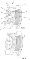
Fig. 6a awater distributor 1 is shown, having aninsert element 20 where thecheck valve 40 is in a closed position. InFig. 6b thecheck valve 40 is in an open position. Thecheck valve 40 comprises adisc 41, apiston 42 and aspring 43. To hold thecheck valve 40 in place, theinsert element 20 comprises apiston holder 27. Thevalve 40 is able to move from a closed position to an open position by thedisc 41 and the associatedpiston 42 moving back and forth. In the closed position, thedisc 41 seals theoutlet section 12 of theconnector 10, thus reducing the amount of "post-flush" that otherwise would potentially enter thesanitary equipment 50. In the closed position, thespring 43 exerts a force on thedisc 41, pressing thedisc 41 against aseat 28 of theinsert element 20, thereby preventing the water from entering theoutlet section 12 of theconnector 10. - The
seat 28 is preferably a circumferential edge surrounding an open hole in which thedisc 41, having a slightly larger diameter, is arranged. - The
check valve 40 will open, i.e. move from the closed position to the open position when the water pressure in theconnector 10 is above a threshold value, i.e. at the start of a flushing sequence. This is shown inFig. 6b . Typically, the threshold value is about 0.1 bar. When the flushing water stops, the pressure is reduced and thecheck valve 40 will return to its closed position by means of the biasing force of thespring 43. - Typically, the
piston 42 and/or thepiston holder 26 is/are made of polybutylene terephthalate (PBT). - The
spring 43 may be conical. This allows for less axial length when compressed, improved axial alignment, and better stability. - Another specific embodiment of an
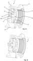
insert element 20 of awater distributor 1 is shown inFigs. 7a-b . While some components are identical to the embodiment described with reference toFigs. 6a-b , these will not be described here. - In this embodiment, the
disc 41 of thecheck valve 40 comprises a sealing 44 located at the outer periphery of thedisc 41. The sealing 44 is configured to mate with aseat 19 of theconnector 10. Theseat 19 is preferably in the form of a circular flange extending radially inwards, as shown inFigs. 7a-b . Hence, in this embodiment thedisc 41 contacts theconnector 10 rather than a seat of theinsert element 20. - Thus, in the closed position of the
valve 40, the sealing 44 mates with asurface 19 of theconnector 10 and further prevents the "post-flush" from entering the associatedsanitary equipment 50, thereby reducing the discolouring of the sanitary equipment. The sealing 44 may e.g. be made of ethylene propylene diene monomer rubber (EPDM). - In the shown embodiment the
piston 42 is provided withflexible legs 42a at its rear end. Theselegs 42a are preferably provided with barbs or hooks, preventing thepiston 42 to move beyond these features. Insertion of thepiston 42 into thepiston holder 27 may still be accomplished due to the flexibility of thelegs 42a. - A further embodiment of the
water distributor 1 is shown inFigs. 8a-b . In this embodiment, being very similar to the embodiment shown inFigs. 7a-b , the sealing 44 extends across theentire disc 41. This facilitates assembly of thecheck valve 40, and adds robustness to the closing operation of thecheck valve 40. - Another embodiment of the
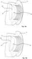
water distributor 1 is shown inFigs. 9a-b . Here, theinsert element 20 is similar to what has been described with reference toFigs. 8a-b . However, inFigs. 8a-b thedisc 41 of thecheck valve 40 does not have an added sealing, but instead the disc is provided with acircumferential ridge 45 arranged at the edge of thedisc 41. Thecircumferential ridge 45, seen in particular inFig. 9b , will assist in proper closure of thecheck valve 40. - Further, the
disc 41 seals againstseat 28 of theinsert element 20 in a manner being similar to what has been described with reference toFigs. 6a-b . In the shown example, theseat 28 is supported by anotherseat 19 of theconnector 10 acting as a reinforcement for theinsert element seat 28. - In
Figs. 10a-b another example of awater distributor 1 is shown. Here, thecheck valve 40 is similar to thecheck valve 40 described with reference toFigs. 9a-b . However, some differences will be specifically discussed. As can be seen inFigs. 10a-b thedisc 41 is not supported by any piston, but instead thespring 43 acts as a support for thedisc 41. Thedisc 41 is provided with a rear knob-like feature 46 around which thespring 43 is arranged. By removing the piston theinsert element 20 does not require a through hole for guiding the piston, thereby improving simplicity and robustness of thewater distributor 1. - Further, the
part 27 previously acting as a piston holder but now acting more as a holder for thespring 43 and thedisc 41, is provided with atab 29. By pressing thetab 29 thepart 27 will deflect thereby decreasing the friction between theinsert element 20 and theconnector 10, thereby facilitating removal of theinsert element 20. - Another example is shown in
Figs. 11a-b . The showninsert element 20 is very similar to theinsert element 20 ofFigs. 10a-b , however thetab 29 is provided in cooperation with a lockingridge 29a. Also, arear wall 12c of theoutlet section 12 of theconnector 10 is provided with arecess 12d in which thelocking ridge 29a will fit. When theinsert element 20 is inserted into theconnector 20, theholder 27 will deflect to allow thelocking ridge 29a to pass until it reaches therecess 12d. The lockingridge 29a will snap into therecess 12d, thereby locking the position of theinsert element 20 and preventing undesired removal of theinsert element 20. When theinsert element 20 is to be removed for cleaning or replacement, thetab 29 is pressed thereby deflecting the position of the lockingridge 29a such that theinsert element 20 can be moved out from theconnector 10. - A yet further example is shown in
Figs. 12a-b . Here, theinsert element 20 is provided with acheck valve 40, thereby achieving the same basic functionality as has been previously described. - In the shown example, the
check valve 40 comprises apivotable flap 60 acting as thedisc 41 previously described. Theflap 60 is biased, preferably by intrinsic properties of thepivotable connection 61, to close thecheck valve 40 by providing a seal against theconnector 10. When water pressure is acting on theflap 60, theflap 60 will pivot thereby opening thecheck valve 40 and allowing for the flushing operation. As soon as the water pressure is removed by termination of the flush, theflap 60 will return to its idle position in which thecheck valve 40 is closed. It should be mentioned that in the shown example, theinsert element 20 is shown very schematically omitting several details shown previously. - In
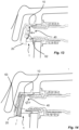
Fig. 13 a further example of awater distributor 1 is shown. Here, theinsert element 20 comprises acheck valve 40 which has the form of a flexible andbiased membrane 62, whereby themembrane 62 acts as thedisc 41 previously described. In an idle position, where no water pressure is acting on themembrane 62, themembrane 62 is urged towards a closed position sealing against theconnector 10. Upon an applied water pressure, themembrane 62 will flex inwards in the direction of the incoming water, thereby opening a flow path for the water. - A yet further example is shown in
Fig. 14 . Here, thecheck valve 40 is formed by theinsert element 20 per se, and adisc spring 63 arranged in between theinsert element 20 and the connector wall. Thedisc spring 63 presses theinsert element 20 towards the connector in a sealed manner. Upon water being allowed to flow, the water will hit theinsert element 20 thereby compressing thedisc spring 63, which in turn allows theinsert element 20 to move in the direction of the water thereby opening a flow path for the water.
Claims (15)
- A water distributor (1) comprising:a connector (10) configured to be mounted to an associated sanitary equipment (50), said connector (10) comprising an inlet section (11) configured to receive water from a water supply, and an outlet section (12) configured to discharge water into the associated sanitary equipment (50),an insert element (20) configured to be removably inserted into the outlet section (12) and forming a baffle for water flowing into the outlet section (12),characterized in thatthe insert element (20) comprises a check valve (40).
- The water distributor (1) according to claim 1, wherein the check valve (40) comprises a disc (41) being moveable between a closed position and an open position, and wherein in the closed position, the disc (41) closes the inlet section (11) of the connector (10).
- The water distributor (1) according to claim 2, wherein the disc (41) is arranged inside of a flange (28) of the insert element (20).
- The water distributor (1) according to claim 2 or 3, wherein the disc (41) is connected to a piston (42) being supported by a piston holder (27) of the insert element (20).
- The water distributor (1) according to any of claims 2 to 4, wherein the check valve (40) is configured to bias the disc (41) towards its closed position, preferably the check valve (40) comprises a spring (43) arranged to bias the disc (41) towards its closed position.
- The water distributor (1) according to claim 5, wherein the spring (43) has a spring constant being selected so that the check valve (40) opens by the pressure of the incoming water from the water supply.
- The water distributor (1) according to claim 5 or 6, wherein the spring (43) is a conical or a cylindrical compression spring.
- The water distributor (1) according to any of claims 2 to 7, wherein the disc (41) comprises a sealing (44).
- The water distributor (1) according to claim 8, wherein the sealing (44) substantially covers the outer rim and/or edge of the disc (41).
- The water distributor (1) according to any of the preceding claims, wherein the insert element (20) has a longitudinal axis (LD) extending in parallel with the insertion direction into the outlet section (12), and a transverse axis (TD) extending in parallel with the width direction of the outlet section (12) and perpendicular to the longitudinal axis (LD), wherein the insert element (20) comprises at least one water channel (26) extending non-parallel with each one of the longitudinal axis (LD) and the transverse axis (TD).
- The water distributor (1) according to claim 10, wherein the insert element (20) comprises a plurality of water channels (26) configured to discharge water at different directions.
- The water distributor (1) according to any of the preceding claims, wherein the insert element (20) comprises a snap-lock (29a) configured to secure the insert element (20) to the connector (10).
- A water distributor (1) comprising:a connector (10) configured to be mounted to an associated sanitary equipment (50), said connector (10) comprising an inlet section (11) configured to receive water from a water supply, and an outlet section (12) configured to discharge water into the associated sanitary equipment (50),an insert element (20) configured to be removably inserted into the outlet section (12) and forming a baffle for water flowing into the outlet section (12),characterized in thatthe insert element (20) has a longitudinal axis (LD) extending in parallel with the insertion direction into the outlet section (12), and a transverse axis (TD) extending in parallel with the width direction of the outlet section (12) and perpendicular to the longitudinal axis (LD), wherein the insert element (20) comprises at least one water channel (26) extending non-parallel with each one of the longitudinal axis (LD) and the transverse axis (TD).
- An insert element (20) configured to form part of the water distributor (1) according to any of the preceding claims.
- A sanitary equipment (50), such as a urinal or a WC, comprising a water distributor (1) according to any of the preceding claims.
Priority Applications (1)
| Application Number | Priority Date | Filing Date | Title |
|---|---|---|---|
| EP23195478.5A EP4520885A1 (en) | 2023-09-05 | 2023-09-05 | Water distributor |
Applications Claiming Priority (1)
| Application Number | Priority Date | Filing Date | Title |
|---|---|---|---|
| EP23195478.5A EP4520885A1 (en) | 2023-09-05 | 2023-09-05 | Water distributor |
Publications (1)
| Publication Number | Publication Date |
|---|---|
| EP4520885A1 true EP4520885A1 (en) | 2025-03-12 |
Family
ID=87933856
Family Applications (1)
| Application Number | Title | Priority Date | Filing Date |
|---|---|---|---|
| EP23195478.5A Pending EP4520885A1 (en) | 2023-09-05 | 2023-09-05 | Water distributor |
Country Status (1)
| Country | Link |
|---|---|
| EP (1) | EP4520885A1 (en) |
Citations (4)
| Publication number | Priority date | Publication date | Assignee | Title |
|---|---|---|---|---|
| DE956660C (en) * | 1954-07-25 | 1957-01-24 | Ing Hans Aue | Flush pipe connection to the toilet bowl |
| EP3825480A1 (en) * | 2019-11-21 | 2021-05-26 | Geberit International AG | Flush water distributor |
| EP4015720A1 (en) | 2020-12-16 | 2022-06-22 | Geberit International AG | Bathrrom fitting |
| ES2922153A1 (en) * | 2021-02-25 | 2022-09-09 | Roca Sanitario Sa | TOILET (Machine-translation by Google Translate, not legally binding) |
-
2023
- 2023-09-05 EP EP23195478.5A patent/EP4520885A1/en active Pending
Patent Citations (4)
| Publication number | Priority date | Publication date | Assignee | Title |
|---|---|---|---|---|
| DE956660C (en) * | 1954-07-25 | 1957-01-24 | Ing Hans Aue | Flush pipe connection to the toilet bowl |
| EP3825480A1 (en) * | 2019-11-21 | 2021-05-26 | Geberit International AG | Flush water distributor |
| EP4015720A1 (en) | 2020-12-16 | 2022-06-22 | Geberit International AG | Bathrrom fitting |
| ES2922153A1 (en) * | 2021-02-25 | 2022-09-09 | Roca Sanitario Sa | TOILET (Machine-translation by Google Translate, not legally binding) |
Similar Documents
| Publication | Publication Date | Title |
|---|---|---|
| CN102076599B (en) | Centerset faucet with mountable spout | |
| US11525254B2 (en) | Electronic flush valve system for tankless water fixtures | |
| US20230265644A1 (en) | Rim jet nozzle system for toilets | |
| KR20190132408A (en) | Suction device. | |
| CN108903738B (en) | Backflow prevention assembly and dispenser | |
| FI117298B (en) | vacuum Drainage | |
| US6554018B1 (en) | Water closet flushing system | |
| CN108223893B (en) | Flushing valve | |
| US6959905B2 (en) | Pinch valve element for plumbing fixture flush valve | |
| US10017929B2 (en) | Discharge valve apparatus, flush water tank apparatus, and flush toilet | |
| US20060060242A1 (en) | Mains pressure flusher valve | |
| US12497769B2 (en) | Flush toilet apparatus | |
| US6276390B1 (en) | Combination air release valve | |
| CA3184078A1 (en) | Conduit connectors and fluid assemblies for enteral feed pumps, and methods thereof | |
| CN105992541B (en) | One-Piece Three-Way Elastomeric Valve | |
| WO1998006910A1 (en) | Improved mains pressure flusher valve | |
| US20160161010A1 (en) | Unitary Diaphragm | |
| TWI892806B (en) | Sanitary washing equipment | |
| CN111287308B (en) | Siphon for a shower tray and shower tray | |
| CN219411109U (en) | Flushing valve body and bathroom equipment | |
| RU2787801C1 (en) | Sewer check valve | |
| CN221857710U (en) | Valve core and water-using equipment using same | |
| JP2007187187A (en) | Diaphragm packing for water shutoff valve | |
| CN114263250B (en) | A valve and a toilet using the valve | |
| US8887753B2 (en) | In-line water trap |
Legal Events
| Date | Code | Title | Description |
|---|---|---|---|
| PUAI | Public reference made under article 153(3) epc to a published international application that has entered the european phase |
Free format text: ORIGINAL CODE: 0009012 |
|
| STAA | Information on the status of an ep patent application or granted ep patent |
Free format text: STATUS: THE APPLICATION HAS BEEN PUBLISHED |
|
| AK | Designated contracting states |
Kind code of ref document: A1 Designated state(s): AL AT BE BG CH CY CZ DE DK EE ES FI FR GB GR HR HU IE IS IT LI LT LU LV MC ME MK MT NL NO PL PT RO RS SE SI SK SM TR |
|
| STAA | Information on the status of an ep patent application or granted ep patent |
Free format text: STATUS: REQUEST FOR EXAMINATION WAS MADE |
|
| 17P | Request for examination filed |
Effective date: 20250911 |