EP4520855A1 - Carbon dioxide conversion device and carbon dioxide conversion method - Google Patents
Carbon dioxide conversion device and carbon dioxide conversion method Download PDFInfo
- Publication number
- EP4520855A1 EP4520855A1 EP24188581.3A EP24188581A EP4520855A1 EP 4520855 A1 EP4520855 A1 EP 4520855A1 EP 24188581 A EP24188581 A EP 24188581A EP 4520855 A1 EP4520855 A1 EP 4520855A1
- Authority
- EP
- European Patent Office
- Prior art keywords
- flow rate
- carbon dioxide
- electrolysis cell
- rate adjusting
- supply
- Prior art date
- Legal status (The legal status is an assumption and is not a legal conclusion. Google has not performed a legal analysis and makes no representation as to the accuracy of the status listed.)
- Pending
Links
- CURLTUGMZLYLDI-UHFFFAOYSA-N Carbon dioxide Chemical compound O=C=O CURLTUGMZLYLDI-UHFFFAOYSA-N 0.000 title claims abstract description 260
- 229910002092 carbon dioxide Inorganic materials 0.000 title claims abstract description 139
- 239000001569 carbon dioxide Substances 0.000 title claims abstract description 134
- 238000006243 chemical reaction Methods 0.000 title claims abstract description 52
- 238000000034 method Methods 0.000 title claims description 51
- 238000005868 electrolysis reaction Methods 0.000 claims abstract description 148
- 230000004044 response Effects 0.000 claims abstract description 4
- 230000003247 decreasing effect Effects 0.000 claims description 6
- 239000007789 gas Substances 0.000 description 68
- 239000012530 fluid Substances 0.000 description 34
- 239000007788 liquid Substances 0.000 description 25
- XLYOFNOQVPJJNP-UHFFFAOYSA-N water Substances O XLYOFNOQVPJJNP-UHFFFAOYSA-N 0.000 description 24
- UGFAIRIUMAVXCW-UHFFFAOYSA-N Carbon monoxide Chemical compound [O+]#[C-] UGFAIRIUMAVXCW-UHFFFAOYSA-N 0.000 description 23
- 229910002091 carbon monoxide Inorganic materials 0.000 description 23
- 229910001868 water Inorganic materials 0.000 description 23
- 230000007423 decrease Effects 0.000 description 12
- 239000003463 adsorbent Substances 0.000 description 11
- -1 amine compound Chemical class 0.000 description 11
- 238000010586 diagram Methods 0.000 description 10
- 239000012528 membrane Substances 0.000 description 10
- 238000001179 sorption measurement Methods 0.000 description 10
- QVGXLLKOCUKJST-UHFFFAOYSA-N atomic oxygen Chemical compound [O] QVGXLLKOCUKJST-UHFFFAOYSA-N 0.000 description 9
- 239000001301 oxygen Substances 0.000 description 9
- 229910052760 oxygen Inorganic materials 0.000 description 9
- 239000000243 solution Substances 0.000 description 9
- 239000003054 catalyst Substances 0.000 description 8
- 239000008151 electrolyte solution Substances 0.000 description 8
- 238000011084 recovery Methods 0.000 description 8
- 239000000126 substance Substances 0.000 description 8
- 238000010521 absorption reaction Methods 0.000 description 7
- 230000008569 process Effects 0.000 description 7
- OKTJSMMVPCPJKN-UHFFFAOYSA-N Carbon Chemical compound [C] OKTJSMMVPCPJKN-UHFFFAOYSA-N 0.000 description 6
- 239000001257 hydrogen Substances 0.000 description 6
- 229910052739 hydrogen Inorganic materials 0.000 description 6
- BVKZGUZCCUSVTD-UHFFFAOYSA-L Carbonate Chemical compound [O-]C([O-])=O BVKZGUZCCUSVTD-UHFFFAOYSA-L 0.000 description 5
- 150000001412 amines Chemical class 0.000 description 5
- 150000001722 carbon compounds Chemical class 0.000 description 5
- 239000010457 zeolite Substances 0.000 description 5
- BVKZGUZCCUSVTD-UHFFFAOYSA-M Bicarbonate Chemical compound OC([O-])=O BVKZGUZCCUSVTD-UHFFFAOYSA-M 0.000 description 4
- MYMOFIZGZYHOMD-UHFFFAOYSA-N Dioxygen Chemical compound O=O MYMOFIZGZYHOMD-UHFFFAOYSA-N 0.000 description 4
- UFHFLCQGNIYNRP-UHFFFAOYSA-N Hydrogen Chemical compound [H][H] UFHFLCQGNIYNRP-UHFFFAOYSA-N 0.000 description 4
- 239000007864 aqueous solution Substances 0.000 description 4
- 230000007812 deficiency Effects 0.000 description 4
- 229910001882 dioxygen Inorganic materials 0.000 description 4
- VNWKTOKETHGBQD-UHFFFAOYSA-N methane Chemical compound C VNWKTOKETHGBQD-UHFFFAOYSA-N 0.000 description 4
- 239000000758 substrate Substances 0.000 description 4
- 238000003786 synthesis reaction Methods 0.000 description 4
- RYGMFSIKBFXOCR-UHFFFAOYSA-N Copper Chemical compound [Cu] RYGMFSIKBFXOCR-UHFFFAOYSA-N 0.000 description 3
- OKKJLVBELUTLKV-UHFFFAOYSA-N Methanol Chemical compound OC OKKJLVBELUTLKV-UHFFFAOYSA-N 0.000 description 3
- KWYUFKZDYYNOTN-UHFFFAOYSA-M Potassium hydroxide Chemical compound [OH-].[K+] KWYUFKZDYYNOTN-UHFFFAOYSA-M 0.000 description 3
- VYPSYNLAJGMNEJ-UHFFFAOYSA-N Silicium dioxide Chemical compound O=[Si]=O VYPSYNLAJGMNEJ-UHFFFAOYSA-N 0.000 description 3
- 229910021536 Zeolite Inorganic materials 0.000 description 3
- 239000002250 absorbent Substances 0.000 description 3
- 230000002745 absorbent Effects 0.000 description 3
- 230000015572 biosynthetic process Effects 0.000 description 3
- 229910052802 copper Inorganic materials 0.000 description 3
- 239000010949 copper Substances 0.000 description 3
- 238000009826 distribution Methods 0.000 description 3
- 229910052751 metal Inorganic materials 0.000 description 3
- 239000002184 metal Substances 0.000 description 3
- 239000007787 solid Substances 0.000 description 3
- BHPQYMZQTOCNFJ-UHFFFAOYSA-N Calcium cation Chemical compound [Ca+2] BHPQYMZQTOCNFJ-UHFFFAOYSA-N 0.000 description 2
- JLVVSXFLKOJNIY-UHFFFAOYSA-N Magnesium ion Chemical compound [Mg+2] JLVVSXFLKOJNIY-UHFFFAOYSA-N 0.000 description 2
- 239000004793 Polystyrene Substances 0.000 description 2
- 229910001424 calcium ion Inorganic materials 0.000 description 2
- 101150008672 csn-1 gene Proteins 0.000 description 2
- HNPSIPDUKPIQMN-UHFFFAOYSA-N dioxosilane;oxo(oxoalumanyloxy)alumane Chemical compound O=[Si]=O.O=[Al]O[Al]=O HNPSIPDUKPIQMN-UHFFFAOYSA-N 0.000 description 2
- 239000003792 electrolyte Substances 0.000 description 2
- 230000006870 function Effects 0.000 description 2
- XLYOFNOQVPJJNP-ZSJDYOACSA-N heavy water Substances [2H]O[2H] XLYOFNOQVPJJNP-ZSJDYOACSA-N 0.000 description 2
- 150000002500 ions Chemical class 0.000 description 2
- TWBYWOBDOCUKOW-UHFFFAOYSA-N isonicotinic acid Chemical compound OC(=O)C1=CC=NC=C1 TWBYWOBDOCUKOW-UHFFFAOYSA-N 0.000 description 2
- 229910001416 lithium ion Inorganic materials 0.000 description 2
- 229910001425 magnesium ion Inorganic materials 0.000 description 2
- 239000000463 material Substances 0.000 description 2
- 229920002223 polystyrene Polymers 0.000 description 2
- BWHMMNNQKKPAPP-UHFFFAOYSA-L potassium carbonate Chemical compound [K+].[K+].[O-]C([O-])=O BWHMMNNQKKPAPP-UHFFFAOYSA-L 0.000 description 2
- 238000000926 separation method Methods 0.000 description 2
- 229910001415 sodium ion Inorganic materials 0.000 description 2
- PCCVSPMFGIFTHU-UHFFFAOYSA-N tetracyanoquinodimethane Chemical compound N#CC(C#N)=C1C=CC(=C(C#N)C#N)C=C1 PCCVSPMFGIFTHU-UHFFFAOYSA-N 0.000 description 2
- YAJCYOUHZABXFT-UHFFFAOYSA-N 1-n,4-n-dihydroxybenzene-1,4-dicarboxamide Chemical compound ONC(=O)C1=CC=C(C(=O)NO)C=C1 YAJCYOUHZABXFT-UHFFFAOYSA-N 0.000 description 1
- VEXZGXHMUGYJMC-UHFFFAOYSA-M Chloride anion Chemical compound [Cl-] VEXZGXHMUGYJMC-UHFFFAOYSA-M 0.000 description 1
- JPVYNHNXODAKFH-UHFFFAOYSA-N Cu2+ Chemical compound [Cu+2] JPVYNHNXODAKFH-UHFFFAOYSA-N 0.000 description 1
- LFQSCWFLJHTTHZ-UHFFFAOYSA-N Ethanol Chemical compound CCO LFQSCWFLJHTTHZ-UHFFFAOYSA-N 0.000 description 1
- HBBGRARXTFLTSG-UHFFFAOYSA-N Lithium ion Chemical compound [Li+] HBBGRARXTFLTSG-UHFFFAOYSA-N 0.000 description 1
- 229910019142 PO4 Inorganic materials 0.000 description 1
- 239000002202 Polyethylene glycol Substances 0.000 description 1
- 229910000831 Steel Inorganic materials 0.000 description 1
- SBRYMHBYAANBLO-UHFFFAOYSA-K [Al+3].[Cl-].[Cl-].[Cl-].[Cu] Chemical compound [Al+3].[Cl-].[Cl-].[Cl-].[Cu] SBRYMHBYAANBLO-UHFFFAOYSA-K 0.000 description 1
- YVIGUKCBHOICMS-UHFFFAOYSA-L [Cu](Cl)Cl.[AlH3] Chemical compound [Cu](Cl)Cl.[AlH3] YVIGUKCBHOICMS-UHFFFAOYSA-L 0.000 description 1
- WYTGDNHDOZPMIW-RCBQFDQVSA-N alstonine Natural products C1=CC2=C3C=CC=CC3=NC2=C2N1C[C@H]1[C@H](C)OC=C(C(=O)OC)[C@H]1C2 WYTGDNHDOZPMIW-RCBQFDQVSA-N 0.000 description 1
- LSOTZYUVGZKSHR-UHFFFAOYSA-N anthracene-1,4-dione Chemical compound C1=CC=C2C=C3C(=O)C=CC(=O)C3=CC2=C1 LSOTZYUVGZKSHR-UHFFFAOYSA-N 0.000 description 1
- KGBXLFKZBHKPEV-UHFFFAOYSA-N boric acid Chemical compound OB(O)O KGBXLFKZBHKPEV-UHFFFAOYSA-N 0.000 description 1
- 229910052792 caesium Inorganic materials 0.000 description 1
- JYDDCGYKLAWPGH-UHFFFAOYSA-N carbamic acid piperazine Chemical compound NC(O)=O.NC(O)=O.C1CNCCN1 JYDDCGYKLAWPGH-UHFFFAOYSA-N 0.000 description 1
- 239000003575 carbonaceous material Substances 0.000 description 1
- JYYOBHFYCIDXHH-UHFFFAOYSA-N carbonic acid;hydrate Chemical compound O.OC(O)=O JYYOBHFYCIDXHH-UHFFFAOYSA-N 0.000 description 1
- 239000000969 carrier Substances 0.000 description 1
- 239000000919 ceramic Substances 0.000 description 1
- 230000008859 change Effects 0.000 description 1
- 238000004140 cleaning Methods 0.000 description 1
- 239000003245 coal Substances 0.000 description 1
- UFMZWBIQTDUYBN-UHFFFAOYSA-N cobalt dinitrate Chemical compound [Co+2].[O-][N+]([O-])=O.[O-][N+]([O-])=O UFMZWBIQTDUYBN-UHFFFAOYSA-N 0.000 description 1
- 229910001981 cobalt nitrate Inorganic materials 0.000 description 1
- 239000012921 cobalt-based metal-organic framework Substances 0.000 description 1
- 150000001875 compounds Chemical class 0.000 description 1
- 229910001431 copper ion Inorganic materials 0.000 description 1
- 230000018109 developmental process Effects 0.000 description 1
- 150000002431 hydrogen Chemical class 0.000 description 1
- 239000003014 ion exchange membrane Substances 0.000 description 1
- 239000003446 ligand Substances 0.000 description 1
- 238000004519 manufacturing process Methods 0.000 description 1
- 239000012621 metal-organic framework Substances 0.000 description 1
- VUZPPFZMUPKLLV-UHFFFAOYSA-N methane;hydrate Chemical compound C.O VUZPPFZMUPKLLV-UHFFFAOYSA-N 0.000 description 1
- 238000012986 modification Methods 0.000 description 1
- 230000004048 modification Effects 0.000 description 1
- 239000003345 natural gas Substances 0.000 description 1
- 239000013110 organic ligand Substances 0.000 description 1
- 230000003647 oxidation Effects 0.000 description 1
- 238000007254 oxidation reaction Methods 0.000 description 1
- 239000003208 petroleum Substances 0.000 description 1
- NBIIXXVUZAFLBC-UHFFFAOYSA-K phosphate Chemical compound [O-]P([O-])([O-])=O NBIIXXVUZAFLBC-UHFFFAOYSA-K 0.000 description 1
- 229920001223 polyethylene glycol Polymers 0.000 description 1
- 229920000642 polymer Polymers 0.000 description 1
- 229920005597 polymer membrane Polymers 0.000 description 1
- 239000011148 porous material Substances 0.000 description 1
- 239000011736 potassium bicarbonate Substances 0.000 description 1
- 229910000028 potassium bicarbonate Inorganic materials 0.000 description 1
- 229910000027 potassium carbonate Inorganic materials 0.000 description 1
- TYJJADVDDVDEDZ-UHFFFAOYSA-M potassium hydrogencarbonate Chemical compound [K+].OC([O-])=O TYJJADVDDVDEDZ-UHFFFAOYSA-M 0.000 description 1
- 229910001414 potassium ion Inorganic materials 0.000 description 1
- 150000003141 primary amines Chemical class 0.000 description 1
- 239000002994 raw material Substances 0.000 description 1
- 230000009467 reduction Effects 0.000 description 1
- 230000008929 regeneration Effects 0.000 description 1
- 238000011069 regeneration method Methods 0.000 description 1
- 150000003335 secondary amines Chemical class 0.000 description 1
- 239000004065 semiconductor Substances 0.000 description 1
- 239000000741 silica gel Substances 0.000 description 1
- 229910002027 silica gel Inorganic materials 0.000 description 1
- 239000000377 silicon dioxide Substances 0.000 description 1
- 239000010959 steel Substances 0.000 description 1
- 238000003860 storage Methods 0.000 description 1
- 238000006467 substitution reaction Methods 0.000 description 1
- 238000011144 upstream manufacturing Methods 0.000 description 1
- 238000010792 warming Methods 0.000 description 1
- 238000004056 waste incineration Methods 0.000 description 1
- 239000013159 zeolitic imidazolate framework-69 Substances 0.000 description 1
Images


Classifications
-
- C—CHEMISTRY; METALLURGY
- C25—ELECTROLYTIC OR ELECTROPHORETIC PROCESSES; APPARATUS THEREFOR
- C25B—ELECTROLYTIC OR ELECTROPHORETIC PROCESSES FOR THE PRODUCTION OF COMPOUNDS OR NON-METALS; APPARATUS THEREFOR
- C25B15/00—Operating or servicing cells
- C25B15/02—Process control or regulation
- C25B15/023—Measuring, analysing or testing during electrolytic production
-
- C—CHEMISTRY; METALLURGY
- C25—ELECTROLYTIC OR ELECTROPHORETIC PROCESSES; APPARATUS THEREFOR
- C25B—ELECTROLYTIC OR ELECTROPHORETIC PROCESSES FOR THE PRODUCTION OF COMPOUNDS OR NON-METALS; APPARATUS THEREFOR
- C25B1/00—Electrolytic production of inorganic compounds or non-metals
- C25B1/01—Products
- C25B1/23—Carbon monoxide or syngas
-
- C—CHEMISTRY; METALLURGY
- C25—ELECTROLYTIC OR ELECTROPHORETIC PROCESSES; APPARATUS THEREFOR
- C25B—ELECTROLYTIC OR ELECTROPHORETIC PROCESSES FOR THE PRODUCTION OF COMPOUNDS OR NON-METALS; APPARATUS THEREFOR
- C25B15/00—Operating or servicing cells
- C25B15/08—Supplying or removing reactants or electrolytes; Regeneration of electrolytes
-
- C—CHEMISTRY; METALLURGY
- C25—ELECTROLYTIC OR ELECTROPHORETIC PROCESSES; APPARATUS THEREFOR
- C25B—ELECTROLYTIC OR ELECTROPHORETIC PROCESSES FOR THE PRODUCTION OF COMPOUNDS OR NON-METALS; APPARATUS THEREFOR
- C25B3/00—Electrolytic production of organic compounds
- C25B3/20—Processes
- C25B3/25—Reduction
- C25B3/26—Reduction of carbon dioxide
-
- C—CHEMISTRY; METALLURGY
- C25—ELECTROLYTIC OR ELECTROPHORETIC PROCESSES; APPARATUS THEREFOR
- C25B—ELECTROLYTIC OR ELECTROPHORETIC PROCESSES FOR THE PRODUCTION OF COMPOUNDS OR NON-METALS; APPARATUS THEREFOR
- C25B9/00—Cells or assemblies of cells; Constructional parts of cells; Assemblies of constructional parts, e.g. electrode-diaphragm assemblies; Process-related cell features
- C25B9/70—Assemblies comprising two or more cells
- C25B9/73—Assemblies comprising two or more cells of the filter-press type
- C25B9/77—Assemblies comprising two or more cells of the filter-press type having diaphragms
Definitions
- Embodiments relate to a carbon dioxide conversion device and a carbon dioxide conversion method.
- the carbon dioxide conversion device has electrolysis cell stacks, each electrolysis cell stack being formed by stacking electrolysis cells. In the electrolysis cell stack where the amount of carbon dioxide supplied is insufficient for a load current, the amount of hydrogen generated increases, and an electric load increases due to voltage increase.
- the carbon dioxide conversion device under consideration distributes the supplied carbon dioxide to each electrolysis cell stack from a distribution tube installed upstream of each electrolysis cell stack, and a distribution ratio is determined on a case-by-case basis.
- a carbon dioxide conversion device of an embodiment includes: a carbon dioxide supply part configured to supply a supply gas containing a carbon dioxide gas; a flow rate adjusting part that includes flow rate adjusting valves configured to distribute the supply gas to be supplied from the carbon dioxide supply part; an electrolysis part that includes electrolysis cell stacks configured to receive the supply gas distributed through the flow rate adjusting valves; a voltage measuring part that includes voltmeters configured to measure voltages across the electrolysis cell stacks; and a control part configured to adjust opening degrees of the flow rate adjusting valves in response to voltage signals to be received from the voltmeters.
- connecting includes not only directly connecting but also indirectly connecting, unless otherwise specified. Furthermore, “connecting” herein includes not only physically connecting but also electrically connecting, unless otherwise specified.
- FIG. 1 is a schematic diagram illustrating the example configuration of the carbon dioxide conversion device of the embodiment.
- FIG. 1 illustrates a carbon dioxide conversion device 100.
- the carbon dioxide conversion device 100 includes a carbon dioxide supply part (CO 2 supply part) 1, a flow rate adjusting part 2, an electrolysis part 3, a voltage measuring part 4, a control part 5, a power supply 6, a cooler 7, a gas-liquid separator 8, a purifying part 9, a gas-liquid separator 10, a cooler 11, a gas-liquid separator 12, a water removal part (H 2 O removal part) 13, a carbon dioxide recovery part (CO 2 recovery part) 14, a cooler 15, a tank 16, and a pump 17.
- FIG. 2 is a diagram to further explain the example configuration of some of components illustrated in FIG. 1 .
- FIG. 2 illustrates the carbon dioxide supply part 1, the flow rate adjusting part 2, the electrolysis part 3, the voltage measuring part 4, and the control part 5.
- the carbon dioxide supply part 1 includes, for example, a carbon dioxide supply source SS.
- the carbon dioxide supply source SS can, for example, supply a supply gas containing carbon dioxide gas to the electrolysis part 3.
- the carbon dioxide supply part 1 is connected to the electrolysis part 3, for example, through the flow rate adjusting part 2.
- the carbon dioxide conversion device may have a humidifier to humidify the carbon dioxide gas from the carbon dioxide supply source SS and supply the gas humidified by the humidifier to the electrolysis part 3.
- the carbon dioxide supply source SS can, for example, separate and recover carbon dioxide gas from an emission gas containing carbon dioxide gas (CO 2 -containing gas) discharged from facilities such as thermal power plants, waste incineration plants, and steel plants, and supply the supply gas containing the separated carbon dioxide gas to the electrolysis part 3.
- an emission gas containing carbon dioxide gas CO 2 -containing gas
- a chemical absorption method using a chemical absorbent such as an amine solution for example, a chemical absorption method using a chemical absorbent such as an amine solution, a physical absorption method using a physical absorbent such as methanol or a polyethylene glycol solution, a solid absorption method using a solid absorbent such as an amine compound, a membrane separation method using a carbon dioxide separation membrane, a physical adsorption method using an inorganic substance such as zeolite as an adsorbent, a pressure swing adsorption (PSA) method, a thermal swing adsorption (TSA) method, and other methods can be used.
- a chemical absorption method using a chemical absorbent such as an amine solution
- a physical absorption method using a physical absorbent such as methanol or a polyethylene glycol solution
- a solid absorption method using a solid absorbent such as an amine compound
- a membrane separation method using a carbon dioxide separation membrane for example, a physical adsorption method using
- the emission gas is supplied to an absorption tower where the amine solution is sprayed, and the amine solution that has absorbed carbon dioxide is heated in a regeneration tower to recover carbon dioxide emitted from the amine solution.
- Various methods and devices capable of recovering carbon dioxide from the emission gas (CO 2 -containing gas) can be applied to the carbon dioxide supply source SS.
- the flow rate adjusting part 2 includes, for example, a flow rate adjusting valve FC.
- the flow rate adjusting valve FC can adjust a flow rate of the supply gas from the carbon dioxide supply source SS.
- the flow rate adjusting part 2 includes flow rate adjusting valves FC.
- the flow rate adjusting valves FC are provided, for example, in a middle of pipes that branch out on the way from the carbon dioxide supply part 1 to the electrolysis part 3 and can distribute the supply gas from the carbon dioxide supply part 1.
- FIG. 2 illustrates flow rate adjusting valves FC1, FC2, FC3, FC4, and FC5 as the flow rate adjusting valves FC
- the number of the flow rate adjusting valves FC can be "n - 1" (n being a natural number of two or more) and is not limited to the number illustrated in FIG. 2 .
- the electrolysis part 3 includes, for example, an electrolysis cell stack CS.
- the electrolysis cell stack CS can receive, for example, the supply gas distributed from the flow rate adjusting part 2 and a supply liquid supplied from the tank 16 through the pump 17.
- the electrolysis cell stack CS can, for example, perform an electrolytic reaction using the supply gas and the supply liquid.
- the electrolysis part 3 includes electrolysis cell stacks CS.
- FIG. 2 illustrates electrolysis cell stacks CS1, CS2, CS3, CS4, CS5, and CS6 as the electrolysis cell stacks CS, but the number of the electrolysis cell stacks CS can be n (n being a natural number of two or more) and is not limited to the number illustrated in FIG. 2 .
- the carbon dioxide conversion device may not have, for example, the flow rate adjusting valve FC corresponding to the n-th electrolysis cell stack CS.
- the n-th electrolysis cell stack CS may not be connected to any flow rate adjusting valve FC.
- the electrolysis cell stack CS1 is connected to the flow rate adjusting valve FC1.
- the electrolysis cell stack CS2 is connected to the flow rate adjusting valve FC2.
- the electrolysis cell stack CS3 is connected to the flow rate adjusting valve FC3.
- the electrolysis cell stack CS4 is connected to the flow rate adjusting valve FC4.
- the electrolysis cell stack CS5 is connected to the flow rate adjusting valve FC5.
- the electrolysis cell stack CS6 is connected to a pipe from the carbon dioxide supply part 1 to the electrolysis part 3 and is not connected to any flow rate adjusting valve FC.
- FIG. 3 is a cross-sectional schematic diagram illustrating an example structure of the electrolysis cell stack CS.
- the electrolysis cell stack CS illustrated in FIG. 3 has a cathode 21, an anode 22, a membrane 23, and a flow path plate 24.
- FIG. 3 illustrates X, Y, and Z axes. The X, Y, and Z axes intersect each other perpendicularly. The Z axis is along a thickness direction of a carbon dioxide electrolysis cell 20.
- FIG. 3 illustrates a portion of an X-Z cross-section including the X and Z axes.
- FIG. 3 illustrates the cathodes 21, the anodes 22, the membranes 23, and the flow path plates 24.
- the cathode 21, anode 22, and membrane 23 are stacked in the Z-axis direction, for example, to form the carbon dioxide electrolysis cell 20.
- An example of the electrolysis cell stack CS includes the carbon dioxide electrolysis cell stack.
- the electrolysis cell stack CS has, for example, the carbon dioxide electrolysis cells 20.
- the carbon dioxide electrolysis cells 20 are stacked across the flow path plate 24.
- the carbon dioxide electrolysis cells 20 may, for example, be disposed between supporting members not illustrated.
- the number of stacks of the carbon dioxide electrolysis cells 20 is not limited, but is, for example, eight or more.
- the cathode 21 is connected to the power supply 6, for example, through a cathode current collector provided at an end portion of the electrolysis cell stack CS.
- the cathode 21 can, for example, reduce carbon dioxide to produce carbon compounds such as carbon monoxide.
- the cathode 21 further has a catalyst that, for example, promotes the electrolytic reaction.
- the catalyst is supported on a surface of a conductive substrate, for example, such as metal.
- the catalyst may form a catalyst layer provided on the surface of the conductive substrate.
- the anode 22 is connected to the power supply 6, for example, through an anode current collector provided at the end portion of the electrolysis cell stack CS.
- the anode 22 can, for example, oxidize water to produce oxygen gas.
- the anode 22 further has a catalyst that, for example, promotes the electrolytic reaction.
- the catalyst is supported on a surface of a conductive substrate, for example, such as metal.
- the catalyst may form a catalyst layer on the surface of the conductive substrate.
- the membrane 23 is disposed between the cathode 21 and anode 22, for example.
- the membrane 23 may be provided in contact with each of the cathode 21 and anode 22.
- the membrane 23 allows, for example, distribution of ions such as hydrogen ions (H + ), hydroxide ions (OH - ), carbonate ions (CO 3 2- ), and hydrogen carbonate ions (HCO 3 - ).
- the membrane 23 has, for example, at least an ion exchange membrane or a porous membrane.
- the flow path plate 24 is provided to separate two carbon dioxide electrolysis cells 20.
- the flow path plate 24 can, for example, isolate an atmosphere between adjacent carbon dioxide electrolysis cells 20.
- the flow path plate 24 can be formed, for example, using a material such as metal, carbon material, or conductive ceramic.
- the flow path 24a is provided on the cathode 21 side surface of the flow path plate 24 and faces the cathode 21.
- the flow path 24a can, for example, distribute a fluid containing the supply gas or reduction products such as carbon compounds.
- the flow path 24a can, for example, form a cathode chamber.
- the flow path 24a has, for example, an inlet connected to the flow rate adjusting valve FC and an outlet from which a fluid containing carbon compounds such as carbon monoxide (cathode fluid) is discharged.
- the flow path 24b is provided on the anode 22 side surface (opposite side of flow path 24a) of the flow path plate 24 and faces the anode 22.
- the flow path 24b can, for example, distribute a fluid containing the supply liquid, water and oxygen gas, or oxidation products such as carbon dioxide gas.
- the flow path 24b can, for example, form an anode chamber.
- the flow path 24b has, for example, an inlet connected to the pump 17 and an outlet from which a fluid containing oxygen (anode fluid) is discharged.
- the supply liquid contains, for example, an electrolytic solution.
- the electrolytic solutions include a solution using water (H 2 O), for example, an aqueous solution containing any electrolyte.
- the aqueous solutions containing electrolytes include aqueous solutions containing ions such as phosphate ions (PO 4 2- ), borate ions (BO 3 3- ), sodium ions (Na + ), potassium ions (K + ), calcium ions (Ca 2+ ), lithium ions (Li + ), cesium ions (Cs + ), magnesium ions (Mg 2+ ), chloride ions (Cl - ), hydrogen carbonate ions (HCO 3 - ), carbonate ions (CO 3 2- ), and hydroxide ions (OH - ).
- the electrolytic solutions include electrolytic solutions such as alkaline aqueous solutions in which compounds such as KOH, KHCO 3 , and K 2 CO 3 are dissolved.
- the voltage measuring part 4 includes, for example, a voltmeter VM.
- the voltmeter VM can, for example, measure a voltage to be applied to the electrolysis cell stack CS during electrolysis operation.
- the voltage measuring part 4 can transmit a data signal indicating the voltage to be measured by the voltmeter VM to the control part 5.
- the voltage measuring part 4 includes voltmeters VM.
- FIG. 2 illustrates voltmeters VM1, VM2, VM3, VM4, VM5, and VM6 as the voltmeters VM, but the number of the voltmeters VM can be n (n is a natural number of 2 or more) and is not limited to the number illustrated in FIG. 2 .
- the voltmeter VM may be provided for each electrolysis cell stack CS, for example.
- the control part 5 has, for example, a controller CT.
- the controller CT can receive the data signals (voltage signals) indicating the measured voltages from the voltmeters VM.
- the controller CT can control opening degrees of the flow rate adjusting valves FC using the data of the measured voltages contained in the voltage signals.
- the controller CT can, for example, generate and output a control signal to control the opening degree of the flow rate adjusting valve FC according to the measured voltage.
- a dotted arrow illustrated in FIG. 2 indicates the control signal.
- the controller CT can, for example, generate control signals.
- Each control signal can control the opening degree of the flow rate adjusting valve FC corresponding to the voltage to be measured by each voltmeter VM.
- the controller CT is connected to each of the flow rate adjusting valves FC, for example, by a wired or wireless connection.
- the controller CT may be connected to at least one of the carbon dioxide supply source SS and the electrolysis cell stack CS by a wired or wireless connection and may control operation of at least one of the carbon dioxide supply source SS and the electrolysis cell stack CS.
- the controller CT has hardware with an arithmetic device such as a processor, for example.
- Each operation may be stored as an operation program in a computer-readable recording medium, such as memory, and each operation may be executed by reading the operation program stored in the recording medium by the hardware as appropriate.
- the power supply 6 can, for example, supply load currents to the electrolysis cell stacks CS.
- the power supply 6 can, for example, be electrically connected to each of the cathode 21 and anode 22 of the electrolysis cell stack CS, and can supply electric current to the electrolysis cell stack CS through the cathode current collector and anode current collector.
- the cooler 7 can, for example, cool the cathode fluid discharged from the flow path 24a to a predetermined temperature.
- the cooler 7 may, for example, be connected to each of the flow paths 24a, or may be connected to a connection point of the flow paths 24a when the flow paths 24a are connected to each other to form a single cathode discharge flow path.
- the gas-liquid separator 8 can, for example, process the cathode fluid to separate water from the cathode fluid.
- the gas-liquid separator 8 is connected, for example, to a subsequent stage of the cooler 7.
- the purifying part 9 can, for example, separate carbon compounds such as carbon monoxide from the cathode fluid by purifying the cathode fluid processed by the gas-liquid separator 8.
- the purifying part 9 is connected, for example, to a subsequent stage of the gas-liquid separator 8.
- the purifying part 9 can produce the cathode fluid using methods such as a pressure swing adsorption (CO-PSA) method using adsorbents such as, for example, a copper ion-zeolite adsorbent, a copper ion activated carbon adsorbent, a copper chloride-aluminum-crosslinked polystyrene solid adsorbent, a copper chloride-aluminum-activated carbon adsorbent, a cuprammonium cleaning method, a copper aluminum chloride complex solution absorption method, a copper chloride-aluminum-polystyrene polymer complex solution absorption method, a low-temperature method, and other methods.
- CO-PSA pressure swing adsorption
- the purified cathode fluid is contained in a storage container, such as, for example, a not-illustrated tank, or sent to an organic-substance synthesis reactor, such as a methane synthesis reactor, an alcohol synthesizer, or a Fischer-Tropsch reactor, where, for example, carbon monoxide and hydrogen are reacted.
- organic-substance synthesis reactors may be used in place of the purifying part 9, which applies the methods such as CO-PSA.
- purified residual gas is discharged from the purifying part 9.
- the purified residual gas may contain residual carbon monoxide, hydrogen, carbon dioxide, and other gases.
- the gas-liquid separator 10 can process the anode fluid discharged from the flow path 24b to separate gas such as oxygen and carbon dioxide from the anode fluid.
- the gas-liquid separator 10 may be connected to each of the flow paths 24b, for example, or to a connection point of the flow paths 24b when the flow paths 24b are connected to each other to form a single anode discharge flow path.
- the cooler 11 can, for example, cool a fluid containing gas such as oxygen and carbon dioxide separated from the anode fluid by the gas-liquid separator 10 to a predetermined temperature.
- the cooler 11 is connected, for example, to a subsequent stage of the gas-liquid separator 10.
- the gas-liquid separator 12 can, for example, process the fluid cooled by the cooler 11 to separate oxygen gas from the cooled fluid.
- the fluid processed by the gas-liquid separator 12 may be supplied to the tank 16.
- the water removal part 13 can, for example, process the fluid containing oxygen gas and carbon dioxide separated by the gas-liquid separator 12 to remove water remaining in the fluid.
- the water removal part 13 is connected, for example, to a subsequent stage of the gas-liquid separator 12.
- the water removal part 13 has, for example, a water vapor-removing polymer membrane, or a water vapor adsorbent such as zeolite, silica gel, mesoporous silica, or activated carbon.
- the carbon dioxide recovery part 14 can, for example, process the fluid processed by the water removal part 13 to remove carbon dioxide contained in the fluid. This allows carbon dioxide to be recovered.
- the fluid processed by the carbon dioxide recovery part 14 may contain oxygen.
- the carbon dioxide recovery part 14 is connected, for example, to a subsequent stage of the water removal part 13.
- the carbon dioxide recovery part 14 has, for example, a carbon dioxide adsorbent.
- carbon dioxide adsorbents examples include primary or secondary amine carriers, FAU-type zeolites, GIS-type zeolites, using 1,4-benzenedicarbohydroxamic acid as an organic ligand and isonicotinic acid as an auxiliary ligand, Co-MOF (metal-organic frameworks) obtained by reaction with cobalt nitrate, ZIF-69 ( CAS No.
- the carbon dioxide recovery part 14 may use an organic semiconductor such as tetracyanoquinodimethane (CAS No. 1518-16-7 , chemical formula: (NC) 2 CC 6 H 4 C(CN) 2 ) pore material as an oxygen adsorbent and use the pressure swing adsorption (PSA) method or temperature swing adsorption (TSA) method to separate and recover oxygen to consequently recover carbon dioxide.
- PSA pressure swing adsorption
- TSA temperature swing adsorption
- the carbon dioxide recovery part 14 may use a Faradaic electro-swing reactive adsorption method while using poly-1,4-anthraquinone as a carbon dioxide adsorption electrode and polyvinylferrocene as a counter electrode.
- the cooler 15 can, for example, cool the anode fluid processed by the gas-liquid separator 10 to a predetermined temperature.
- the cooler 15 is connected, for example, to a subsequent stage of the gas-liquid separator 10.
- the tank 16 can, for example, contain the anode fluid cooled by the cooler 15.
- the anode fluid cooled by the cooler 15 contains, for example, water and the electrolytic solution.
- the tank 16 is connected, for example, to a subsequent stage of the cooler 15.
- the tank 16 may be connected to a makeup tank. By receiving water from the makeup tank, the anode fluid contained in the tank may be replenished with water.
- the pump 17 can, for example, supply the anode fluid contained in the tank 16 to each of the flow paths 24b of the electrolysis part 3 as a supply liquid.
- the pump 17 is provided, for example, in a middle of a circulation flow path connecting the tank 16 to the inlet of each flow path 24b.
- the carbon dioxide conversion device illustrated in FIG. 1 may have blowers, pumps, compressors, and other devices as appropriate, and these devices may control the flow of gas, liquids, and other fluids.
- the supply gas containing carbon dioxide gas distributed by the flow rate adjusting part 2 from the carbon dioxide supply part 1 is supplied to each flow path 24a through the inlet of each flow path 24a, the supply liquid containing the electrolytic solution is supplied to each flow path 24b through the inlet of each flow path 24b from the tank 16 using the pump 17, and electric current is supplied from the power supply 6 in each electrolysis cell stack CS.
- This allows the electrolytic reaction to take place at each of the cathode 21 and anode 22.
- Carbon dioxide supplied to each flow path 24a is converted to carbon monoxide and hydroxide ions by the electrolytic reaction at the cathode 21.
- This reaction is expressed by Formula (1) below. CO 2 + 2H 2 O + 2e - ⁇ CO + 2OH - ... (1)
- Carbon dioxide, oxygen, and water produced in the anode 22 are discharged from each flow path 24b through the outlet of each flow path 24b as the anode fluid along with the electrolytic solution.
- the supply gas with the flow rate according to the sum of the load currents through the electrolysis cell stacks CS is distributed and supplied to the electrolysis cell stacks, or an equal load current with the theoretical current value according to the flow rate of the supply gas supplied from the carbon dioxide supply part 1 is supplied to the electrolysis cell stacks CS.
- the carbon dioxide supply part 1 has a function to maintain the set value of the flow rate FR CO2 .
- the power supply 6 has a function to maintain the set value of the load current I.
- FIG. 4 is a flowchart to explain an example of a method of adjusting the opening degree of each flow rate adjusting valve FC in the example of the carbon dioxide conversion method.
- a voltage Vi of each electrolysis cell stack CS is measured by the corresponding voltmeter VM to generate a voltage signal (data signal), and a mean voltage of the voltages Vi applied to the electrolysis cell stacks CS (mean stack voltage) Vmean is calculated from the data indicating the measured voltage Vi contained in the generated voltage signal (Step S1).
- the voltage Vi of the electrolysis cell stack CS1 is measured by a voltmeter V1
- the voltage Vi of the electrolysis cell stack CS2 is measured by a voltmeter V2
- the voltages Vi of the electrolysis cell stacks CS3, CS4, and CS5 are measured by voltmeters V3, V4, and V5, respectively.
- the voltage measuring part 4 may measure the voltage Vi across at least one electrolysis cell stack CS in sequence, or the voltages Vi across the electrolysis cell stacks CS simultaneously.
- the mean voltage Vmean may be calculated, for example, by the control part 5 upon receiving the voltage signal, or by an arithmetic device such as a personal computer connected to the control part 5.
- the mean voltage Vmean is determined by dividing the sum of the voltages Vi by the number of the electrolysis cell stacks CS and is expressed, for example, by Equality (7) below.
- Vmean ⁇ Vi / n
- Step S3 the voltage Vi across the target electrolysis cell stack CS is compared with the mean voltage Vmean (Step S3).
- the above comparison is performed, for example, by calculating a difference (Vi - Vmean) between the voltage Vi and the mean voltage Vmean.
- the above calculation may be performed, for example, by the control part 5 or by an arithmetic device such as a personal computer connected to the control part 5.
- Step S4-1 When the value of the voltage Vi is greater (higher) than the value of the mean voltage Vmean (S3: Vi > Vmean), the opening degree of the flow rate adjusting valve FC corresponding to the target electrolysis cell stack CS is increased (Step S4-1). This allows the flow rate of the supply gas supplied to the target electrolysis cell stack CS to be increased.
- the flow rate of the supply gas supplied to the electrolysis cell stack CS1 can be increased by increasing the opening degree of the flow rate adjusting valve FC1.
- the amount of increase of the supply gas is, for example, set appropriately so that the supply gas supplied to the target electrolysis cell stack CS is used without excess or deficiency.
- the opening degree of the flow rate adjusting valve FC corresponding to the target electrolysis cell stack CS is decreased (step S4-2). This allows the flow rate of the supply gas supplied to the target electrolysis cell stack CS to be decreased.
- the flow rate of the supply gas supplied to the electrolysis cell stack CS1 can be decreased by decreasing the opening degree of the flow rate adjusting valve FC1.
- the amount of decrease of the supply gas is, for example, set appropriately so that the supply gas supplied to the target electrolysis cell stack CS is used without excess or deficiency.
- the opening degree of the flow rate adjusting valve FC corresponding to the target electrolysis cell stack CS is not changed (step S4-3).
- the opening degree of the flow rate adjusting valve FC1 is maintained unchanged.
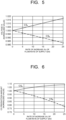
- FIG. 5 is a diagram illustrating a relationship between the rate of increase in the flow rate of the supply gas and the voltage Vi.
- FIG. 5 illustrates the relationship between the rate of increase in the flow rate of the supply gas for each of one electrolysis cell stack CS A and one other electrolysis cell stack CS B and the voltage Vi.
- the voltage Vi is a normalized value, and the value of the voltage Vi based on the specification of the electrolysis cell stack CS is set as 1.000.
- the electrolysis cell stack CS A in which the voltage Vi increases as the flow rate of the supply gas increases, preferably decreases the opening degree of the corresponding flow rate adjusting valve FC to decrease the flow rate of the supply gas until the value of the voltage Vi reaches a reference value.
- the reference value is, for example, 1.000.
- the electrolysis cell stack CS B in which the voltage Vi decreases as the flow rate of the supply gas increases, preferably decreases the opening degree of the corresponding flow rate adjusting valve FC to decrease the flow rate of the supply gas until the value of the voltage Vi reaches the reference value.
- FIG. 6 is a diagram illustrating a relationship between the rate of increase in the flow rate of the supply gas and the amount of carbon monoxide produced.
- FIG. 6 illustrates the relationship between the rate of increase in the flow rate of the supply gas for each of one electrolysis cell stack CS A and one other electrolysis cell stack CS B and the amount of carbon monoxide produced.
- the amount of carbon monoxide produced is a normalized value, and the value of carbon monoxide produced based on the specification of the electrolysis cell stack CS is set as 1.000.
- the electrolysis cell stack CS A in which the amount of carbon monoxide produced increases as the flow rate of the supply gas increases, preferably decreases the opening degree of the corresponding flow rate adjusting valve FC to decrease the flow rate of the supply gas until the amount of carbon monoxide produced reaches a reference value.
- the reference value is, for example, 1.000.
- the electrolysis cell stack CS B in which the amount of carbon monoxide produced decreases as the flow rate of the supply gas increases, preferably decreases the opening degree of the corresponding flow rate adjusting valve FC to decrease the flow rate of the supply gas until the amount of carbon monoxide produced reaches the reference value.
- the flow rate of the supply gas supplied to the electrolysis cell stacks CS can be adjusted by adjusting the opening degree of the corresponding flow rate adjusting valve FC according to the voltage across the electrolysis cell stack CS. Therefore, the carbon dioxide gas can be supplied to the electrolysis cell stacks CS without excess or deficiency, thereby improving utilization efficiency of carbon dioxide in the electrolysis cell stacks CS.
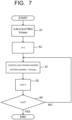
- FIG. 7 is a flowchart to explain another example of the method of adjusting the opening degree of each flow rate adjusting valve FC in the example of the carbon dioxide conversion method.
- the flowchart illustrated in FIG. 7 differs from the flowchart illustrated in FIG. 4 in that it has Step S7 instead of Steps S3 and S4 (S4-1, S4-2, S4-3).
- Step S7 instead of Steps S3 and S4 (S4-1, S4-2, S4-3).
- the parts of the flowchart that differ from the flowchart illustrated in FIG. 4 in another example of the method of adjusting the opening degree of each flow rate adjusting valve FC will be described, and for the other parts, the description of the flowchart illustrated in FIG. 4 can be used as appropriate.
- Step S7 when the flow rate adjusting valve FC has linear characteristics (CV value is proportional to a valve opening degree), the opening degree of the flow rate adjusting valve FC is adjusted in each electrolysis cell stack CS to be proportional to a ratio Vi/Vmean of the voltage Vi to the mean voltage Vmean (opening degree * Vi/Vmean). This operation is repeated until the "n - 1"th electrolysis cell stack CSn-1.
- the flow rate of the supply gas supplied to the electrolysis cell stacks CS can be thereby adjusted.
- the flow rate of the supply gas supplied to the electrolysis cell stack CSn can be adjusted indirectly by adjusting the opening degrees of the flow rate adjusting valves FC corresponding to all other electrolysis cell stacks CS.
- carbon dioxide gas can be supplied to the electrolysis cell stacks CS without excess or deficiency, thereby improving the utilization efficiency of carbon dioxide in the electrolysis cell stacks CS.
- Information indicating the relationship between the load current I and the opening degree corresponding to each flow rate adjusting valve FC may be updated.
- the update may take place, for example, periodically or after the flow rate has stabilized, or at a stage when the difference from the information stored in the control part 5 exceeds a set value.
- the carbon dioxide conversion device may further have an alarm.
- the alarm can generate an alarm after the voltage comparison (Step S3) and before adjusting the opening degree of the flow rate adjusting valve FC when the difference between the voltage Vi of the target electrolysis cell stack CS and the mean voltage Vmean is outside an acceptable range.
- the operation of the target electrolysis cell stack CS may be stopped.
- the electrolysis cell stack CS can be stopped in operation by, for example, stopping the supply of the supply gas and the supply liquid, and the supply of electric current.
- the alarm may, for example, be connected to the control part 5 and controlled by the control part 5.
- the number of flow rate adjusting valves FC is "n - 1" (n is a natural number greater than or equal to 2) and the number of electrolysis cell stacks CS is "n" is described.
- the number of each of the flow rate adjusting valves FC and electrolysis cell stacks CS provided in the carbon dioxide conversion device is not limited thereto.
- the carbon dioxide conversion device may be equipped with any number of flow rate adjusting valves FC and any number of electrolysis cell stacks CS, such as having "n” or more flow rate adjusting valves FC and "n + 1" or more electrolysis cell stacks CS.
Landscapes
- Chemical & Material Sciences (AREA)
- Engineering & Computer Science (AREA)
- Organic Chemistry (AREA)
- Chemical Kinetics & Catalysis (AREA)
- Electrochemistry (AREA)
- Materials Engineering (AREA)
- Metallurgy (AREA)
- Inorganic Chemistry (AREA)
- Analytical Chemistry (AREA)
- Automation & Control Theory (AREA)
- Electrolytic Production Of Non-Metals, Compounds, Apparatuses Therefor (AREA)
Abstract
A carbon dioxide conversion device includes: a carbon dioxide supply part configured to supply a supply gas containing carbon dioxide gas; a flow rate adjusting part that includes flow rate adjusting valves configured to distribute the supply gas to be supplied from the carbon dioxide supply part; an electrolysis part that includes electrolysis cell stacks configured to receive the supply gas distributed through the flow rate adjusting valves; a voltage measuring part that includes voltmeters configured to measure voltages across the electrolysis cell stacks; and a control part configured to adjust opening degrees of the flow rate adjusting valves in response to voltage signals to be received from the voltmeters.
Description
- Embodiments relate to a carbon dioxide conversion device and a carbon dioxide conversion method.
- Global warming progresses have been increased the demand for reducing the use of the carbon dioxide (CO2) sources such as natural gas, coal, and petroleum. In addition, development of chemical synthesis using carbon dioxide as a raw material is underway. As part of this process, there are carbon dioxide conversion devices that electrolyze carbon dioxide to produce carbon monoxide (CO)-containing gas. The carbon dioxide conversion device has electrolysis cell stacks, each electrolysis cell stack being formed by stacking electrolysis cells. In the electrolysis cell stack where the amount of carbon dioxide supplied is insufficient for a load current, the amount of hydrogen generated increases, and an electric load increases due to voltage increase. On the other hand, in the electrolysis cell stack where the amount of carbon dioxide supplied is excessive for the load current, the amount of unreacted carbon dioxide increases, and a carbon monoxide conversion rate decreases. To solve these problems, there is a need for a carbon dioxide conversion device and a carbon dioxide conversion method that equalizes the amount of carbon dioxide supplied to each electrolysis cell stack.
- However, the carbon dioxide conversion device under consideration distributes the supplied carbon dioxide to each electrolysis cell stack from a distribution tube installed upstream of each electrolysis cell stack, and a distribution ratio is determined on a case-by-case basis.
-
-
FIG. 1 is a schematic diagram illustrating an example configuration of a carbon dioxide conversion device of an embodiment. -
FIG. 2 is a diagram to further explain the example configuration of some of components illustrated inFIG. 1 . -
FIG. 3 is a cross-sectional schematic diagram illustrating an example structure of an electrolysis cell stack CS. -
FIG. 4 is a flowchart to explain an example of a method of adjusting an opening degree of each flow rate adjusting valve FC in an example of a carbon dioxide conversion method. -
FIG. 5 is a diagram illustrating a relationship between a rate of increase of a flow rate of a supply gas and a voltage Vi. -
FIG. 6 is a diagram illustrating a relationship between the rate of increase of the flow rate of the supply gas and a production amount of carbon monoxide. -
FIG. 7 is a flowchart to explain another example of the method of adjusting the opening degree of each flow rate adjusting valve FC in the example of the carbon dioxide conversion method. - A carbon dioxide conversion device of an embodiment includes: a carbon dioxide supply part configured to supply a supply gas containing a carbon dioxide gas; a flow rate adjusting part that includes flow rate adjusting valves configured to distribute the supply gas to be supplied from the carbon dioxide supply part; an electrolysis part that includes electrolysis cell stacks configured to receive the supply gas distributed through the flow rate adjusting valves; a voltage measuring part that includes voltmeters configured to measure voltages across the electrolysis cell stacks; and a control part configured to adjust opening degrees of the flow rate adjusting valves in response to voltage signals to be received from the voltmeters.
- Carbon dioxide conversion devices in embodiments will be described hereinafter with reference to the drawings. Substantially the same components are denoted by the same reference signs and explanation thereof may be omitted in some cases in the embodiments described below. The drawings are schematic, and a relationship between a thickness and a planar size, thickness proportions of respective portions, and the like are sometimes different from actual ones.
- In this specification, "connecting" includes not only directly connecting but also indirectly connecting, unless otherwise specified. Furthermore, "connecting" herein includes not only physically connecting but also electrically connecting, unless otherwise specified.
- An example configuration of a carbon dioxide conversion device of an embodiment is described.
FIG. 1 is a schematic diagram illustrating the example configuration of the carbon dioxide conversion device of the embodiment.FIG. 1 illustrates a carbondioxide conversion device 100. - The carbon
dioxide conversion device 100 includes a carbon dioxide supply part (CO2 supply part) 1, a flowrate adjusting part 2, anelectrolysis part 3, avoltage measuring part 4, acontrol part 5, apower supply 6, a cooler 7, a gas-liquid separator 8, a purifyingpart 9, a gas-liquid separator 10, acooler 11, a gas-liquid separator 12, a water removal part (H2O removal part) 13, a carbon dioxide recovery part (CO2 recovery part) 14, acooler 15, atank 16, and apump 17. -
FIG. 2 is a diagram to further explain the example configuration of some of components illustrated inFIG. 1 .FIG. 2 illustrates the carbondioxide supply part 1, the flowrate adjusting part 2, theelectrolysis part 3, thevoltage measuring part 4, and thecontrol part 5. - The carbon
dioxide supply part 1 includes, for example, a carbon dioxide supply source SS. The carbon dioxide supply source SS can, for example, supply a supply gas containing carbon dioxide gas to theelectrolysis part 3. The carbondioxide supply part 1 is connected to theelectrolysis part 3, for example, through the flowrate adjusting part 2. The carbon dioxide conversion device may have a humidifier to humidify the carbon dioxide gas from the carbon dioxide supply source SS and supply the gas humidified by the humidifier to theelectrolysis part 3. - The carbon dioxide supply source SS can, for example, separate and recover carbon dioxide gas from an emission gas containing carbon dioxide gas (CO2-containing gas) discharged from facilities such as thermal power plants, waste incineration plants, and steel plants, and supply the supply gas containing the separated carbon dioxide gas to the
electrolysis part 3. In the carbon dioxide supplypart 1, for example, a chemical absorption method using a chemical absorbent such as an amine solution, a physical absorption method using a physical absorbent such as methanol or a polyethylene glycol solution, a solid absorption method using a solid absorbent such as an amine compound, a membrane separation method using a carbon dioxide separation membrane, a physical adsorption method using an inorganic substance such as zeolite as an adsorbent, a pressure swing adsorption (PSA) method, a thermal swing adsorption (TSA) method, and other methods can be used. For example, in the chemical absorption method and device using the amine solution, the emission gas is supplied to an absorption tower where the amine solution is sprayed, and the amine solution that has absorbed carbon dioxide is heated in a regeneration tower to recover carbon dioxide emitted from the amine solution. Various methods and devices capable of recovering carbon dioxide from the emission gas (CO2-containing gas) can be applied to the carbon dioxide supply source SS. - The flow
rate adjusting part 2 includes, for example, a flow rate adjusting valve FC. The flow rate adjusting valve FC can adjust a flow rate of the supply gas from the carbon dioxide supply source SS. The flowrate adjusting part 2 includes flow rate adjusting valves FC. The flow rate adjusting valves FC are provided, for example, in a middle of pipes that branch out on the way from the carbondioxide supply part 1 to theelectrolysis part 3 and can distribute the supply gas from the carbondioxide supply part 1. AlthoughFIG. 2 illustrates flow rate adjusting valves FC1, FC2, FC3, FC4, and FC5 as the flow rate adjusting valves FC, the number of the flow rate adjusting valves FC can be "n - 1" (n being a natural number of two or more) and is not limited to the number illustrated inFIG. 2 . - The
electrolysis part 3 includes, for example, an electrolysis cell stack CS. The electrolysis cell stack CS can receive, for example, the supply gas distributed from the flowrate adjusting part 2 and a supply liquid supplied from thetank 16 through thepump 17. The electrolysis cell stack CS can, for example, perform an electrolytic reaction using the supply gas and the supply liquid. Theelectrolysis part 3 includes electrolysis cell stacks CS.FIG. 2 illustrates electrolysis cell stacks CS1, CS2, CS3, CS4, CS5, and CS6 as the electrolysis cell stacks CS, but the number of the electrolysis cell stacks CS can be n (n being a natural number of two or more) and is not limited to the number illustrated inFIG. 2 . The carbon dioxide conversion device may not have, for example, the flow rate adjusting valve FC corresponding to the n-th electrolysis cell stack CS. The n-th electrolysis cell stack CS may not be connected to any flow rate adjusting valve FC. The electrolysis cell stack CS1 is connected to the flow rate adjusting valve FC1. The electrolysis cell stack CS2 is connected to the flow rate adjusting valve FC2. The electrolysis cell stack CS3 is connected to the flow rate adjusting valve FC3. The electrolysis cell stack CS4 is connected to the flow rate adjusting valve FC4. The electrolysis cell stack CS5 is connected to the flow rate adjusting valve FC5. The electrolysis cell stack CS6 is connected to a pipe from the carbondioxide supply part 1 to theelectrolysis part 3 and is not connected to any flow rate adjusting valve FC. -
FIG. 3 is a cross-sectional schematic diagram illustrating an example structure of the electrolysis cell stack CS. The electrolysis cell stack CS illustrated inFIG. 3 has a cathode 21, ananode 22, amembrane 23, and aflow path plate 24.FIG. 3 illustrates X, Y, and Z axes. The X, Y, and Z axes intersect each other perpendicularly. The Z axis is along a thickness direction of a carbondioxide electrolysis cell 20.FIG. 3 illustrates a portion of an X-Z cross-section including the X and Z axes.FIG. 3 illustrates the cathodes 21, theanodes 22, themembranes 23, and theflow path plates 24. - The cathode 21,
anode 22, andmembrane 23 are stacked in the Z-axis direction, for example, to form the carbondioxide electrolysis cell 20. - An example of the electrolysis cell stack CS includes the carbon dioxide electrolysis cell stack. The electrolysis cell stack CS has, for example, the carbon
dioxide electrolysis cells 20. The carbondioxide electrolysis cells 20 are stacked across theflow path plate 24. The carbondioxide electrolysis cells 20 may, for example, be disposed between supporting members not illustrated. The number of stacks of the carbondioxide electrolysis cells 20 is not limited, but is, for example, eight or more. - The cathode 21 is connected to the
power supply 6, for example, through a cathode current collector provided at an end portion of the electrolysis cell stack CS. The cathode 21 can, for example, reduce carbon dioxide to produce carbon compounds such as carbon monoxide. The cathode 21 further has a catalyst that, for example, promotes the electrolytic reaction. The catalyst is supported on a surface of a conductive substrate, for example, such as metal. The catalyst may form a catalyst layer provided on the surface of the conductive substrate. - The
anode 22 is connected to thepower supply 6, for example, through an anode current collector provided at the end portion of the electrolysis cell stack CS. Theanode 22 can, for example, oxidize water to produce oxygen gas. Theanode 22 further has a catalyst that, for example, promotes the electrolytic reaction. The catalyst is supported on a surface of a conductive substrate, for example, such as metal. The catalyst may form a catalyst layer on the surface of the conductive substrate. - The
membrane 23 is disposed between the cathode 21 andanode 22, for example. Themembrane 23 may be provided in contact with each of the cathode 21 andanode 22. Themembrane 23 allows, for example, distribution of ions such as hydrogen ions (H+), hydroxide ions (OH-), carbonate ions (CO3 2-), and hydrogen carbonate ions (HCO3 -). Themembrane 23 has, for example, at least an ion exchange membrane or a porous membrane. - The
flow path plate 24 is provided to separate two carbondioxide electrolysis cells 20. Theflow path plate 24 can, for example, isolate an atmosphere between adjacent carbondioxide electrolysis cells 20. Theflow path plate 24 can be formed, for example, using a material such as metal, carbon material, or conductive ceramic. - The
flow path plate 24 hasflow paths 24a and flowpaths 24b. Respective shapes of theflow paths FIG. 3 . The respective shapes of theflow paths flow path plates 24 facing the cathode 21 andanode 22, respectively. - The
flow path 24a is provided on the cathode 21 side surface of theflow path plate 24 and faces the cathode 21. Theflow path 24a can, for example, distribute a fluid containing the supply gas or reduction products such as carbon compounds. Theflow path 24a can, for example, form a cathode chamber. Theflow path 24a has, for example, an inlet connected to the flow rate adjusting valve FC and an outlet from which a fluid containing carbon compounds such as carbon monoxide (cathode fluid) is discharged. - The
flow path 24b is provided on theanode 22 side surface (opposite side offlow path 24a) of theflow path plate 24 and faces theanode 22. Theflow path 24b can, for example, distribute a fluid containing the supply liquid, water and oxygen gas, or oxidation products such as carbon dioxide gas. Theflow path 24b can, for example, form an anode chamber. Theflow path 24b has, for example, an inlet connected to thepump 17 and an outlet from which a fluid containing oxygen (anode fluid) is discharged. - The supply liquid contains, for example, an electrolytic solution. Examples of the electrolytic solutions include a solution using water (H2O), for example, an aqueous solution containing any electrolyte. Examples of the aqueous solutions containing electrolytes include aqueous solutions containing ions such as phosphate ions (PO4 2-), borate ions (BO3 3-), sodium ions (Na+), potassium ions (K+), calcium ions (Ca2+), lithium ions (Li+), cesium ions (Cs+), magnesium ions (Mg2+), chloride ions (Cl-), hydrogen carbonate ions (HCO3 -), carbonate ions (CO3 2-), and hydroxide ions (OH-). Examples of the electrolytic solutions include electrolytic solutions such as alkaline aqueous solutions in which compounds such as KOH, KHCO3, and K2CO3 are dissolved.
- The
voltage measuring part 4 includes, for example, a voltmeter VM. The voltmeter VM can, for example, measure a voltage to be applied to the electrolysis cell stack CS during electrolysis operation. Thevoltage measuring part 4 can transmit a data signal indicating the voltage to be measured by the voltmeter VM to thecontrol part 5. Thevoltage measuring part 4 includes voltmeters VM.FIG. 2 illustrates voltmeters VM1, VM2, VM3, VM4, VM5, and VM6 as the voltmeters VM, but the number of the voltmeters VM can be n (n is a natural number of 2 or more) and is not limited to the number illustrated inFIG. 2 . The voltmeter VM may be provided for each electrolysis cell stack CS, for example. - The
control part 5 has, for example, a controller CT. The controller CT can receive the data signals (voltage signals) indicating the measured voltages from the voltmeters VM. The controller CT can control opening degrees of the flow rate adjusting valves FC using the data of the measured voltages contained in the voltage signals. The controller CT can, for example, generate and output a control signal to control the opening degree of the flow rate adjusting valve FC according to the measured voltage. A dotted arrow illustrated inFIG. 2 indicates the control signal. The controller CT can, for example, generate control signals. Each control signal can control the opening degree of the flow rate adjusting valve FC corresponding to the voltage to be measured by each voltmeter VM. The controller CT is connected to each of the flow rate adjusting valves FC, for example, by a wired or wireless connection. The controller CT may be connected to at least one of the carbon dioxide supply source SS and the electrolysis cell stack CS by a wired or wireless connection and may control operation of at least one of the carbon dioxide supply source SS and the electrolysis cell stack CS. - The controller CT has hardware with an arithmetic device such as a processor, for example. Each operation may be stored as an operation program in a computer-readable recording medium, such as memory, and each operation may be executed by reading the operation program stored in the recording medium by the hardware as appropriate.
- Next, the remaining components of the carbon
dioxide conversion device 100 are further described with reference toFIG. 1 . - The
power supply 6 can, for example, supply load currents to the electrolysis cell stacks CS. Thepower supply 6 can, for example, be electrically connected to each of the cathode 21 andanode 22 of the electrolysis cell stack CS, and can supply electric current to the electrolysis cell stack CS through the cathode current collector and anode current collector. - The cooler 7 can, for example, cool the cathode fluid discharged from the
flow path 24a to a predetermined temperature. The cooler 7 may, for example, be connected to each of theflow paths 24a, or may be connected to a connection point of theflow paths 24a when theflow paths 24a are connected to each other to form a single cathode discharge flow path. - The gas-
liquid separator 8 can, for example, process the cathode fluid to separate water from the cathode fluid. The gas-liquid separator 8 is connected, for example, to a subsequent stage of the cooler 7. - The
purifying part 9 can, for example, separate carbon compounds such as carbon monoxide from the cathode fluid by purifying the cathode fluid processed by the gas-liquid separator 8. Thepurifying part 9 is connected, for example, to a subsequent stage of the gas-liquid separator 8. - The
purifying part 9 can produce the cathode fluid using methods such as a pressure swing adsorption (CO-PSA) method using adsorbents such as, for example, a copper ion-zeolite adsorbent, a copper ion activated carbon adsorbent, a copper chloride-aluminum-crosslinked polystyrene solid adsorbent, a copper chloride-aluminum-activated carbon adsorbent, a cuprammonium cleaning method, a copper aluminum chloride complex solution absorption method, a copper chloride-aluminum-polystyrene polymer complex solution absorption method, a low-temperature method, and other methods. The purified cathode fluid is contained in a storage container, such as, for example, a not-illustrated tank, or sent to an organic-substance synthesis reactor, such as a methane synthesis reactor, an alcohol synthesizer, or a Fischer-Tropsch reactor, where, for example, carbon monoxide and hydrogen are reacted. These organic-substance synthesis reactors may be used in place of thepurifying part 9, which applies the methods such as CO-PSA. After the cathode fluid is purified, purified residual gas is discharged from thepurifying part 9. The purified residual gas may contain residual carbon monoxide, hydrogen, carbon dioxide, and other gases. - The gas-
liquid separator 10 can process the anode fluid discharged from theflow path 24b to separate gas such as oxygen and carbon dioxide from the anode fluid. The gas-liquid separator 10 may be connected to each of theflow paths 24b, for example, or to a connection point of theflow paths 24b when theflow paths 24b are connected to each other to form a single anode discharge flow path. - The cooler 11 can, for example, cool a fluid containing gas such as oxygen and carbon dioxide separated from the anode fluid by the gas-
liquid separator 10 to a predetermined temperature. The cooler 11 is connected, for example, to a subsequent stage of the gas-liquid separator 10. - The gas-
liquid separator 12 can, for example, process the fluid cooled by the cooler 11 to separate oxygen gas from the cooled fluid. The fluid processed by the gas-liquid separator 12 may be supplied to thetank 16. - The
water removal part 13 can, for example, process the fluid containing oxygen gas and carbon dioxide separated by the gas-liquid separator 12 to remove water remaining in the fluid. Thewater removal part 13 is connected, for example, to a subsequent stage of the gas-liquid separator 12. Thewater removal part 13 has, for example, a water vapor-removing polymer membrane, or a water vapor adsorbent such as zeolite, silica gel, mesoporous silica, or activated carbon. - The carbon
dioxide recovery part 14 can, for example, process the fluid processed by thewater removal part 13 to remove carbon dioxide contained in the fluid. This allows carbon dioxide to be recovered. The fluid processed by the carbondioxide recovery part 14 may contain oxygen. The carbondioxide recovery part 14 is connected, for example, to a subsequent stage of thewater removal part 13. The carbondioxide recovery part 14 has, for example, a carbon dioxide adsorbent. Examples of the carbon dioxide adsorbents include primary or secondary amine carriers, FAU-type zeolites, GIS-type zeolites, using 1,4-benzenedicarbohydroxamic acid as an organic ligand and isonicotinic acid as an auxiliary ligand, Co-MOF (metal-organic frameworks) obtained by reaction with cobalt nitrate, ZIF-69 (CAS No. 1018477-10-5, chemical formula: C10H6N5O2ClZn), Cubic [Zn4O(piperazine dicarbamate)3] and other materials can be used to separate and recover carbon dioxide using the pressure swing adsorption (PSA) method or the temperature swing adsorption (TSA) method, depending on the adsorbent. - The carbon
dioxide recovery part 14 may use an organic semiconductor such as tetracyanoquinodimethane (CAS No. 1518-16-7, chemical formula: (NC)2CC6H4C(CN)2) pore material as an oxygen adsorbent and use the pressure swing adsorption (PSA) method or temperature swing adsorption (TSA) method to separate and recover oxygen to consequently recover carbon dioxide. The carbondioxide recovery part 14 may use a Faradaic electro-swing reactive adsorption method while using poly-1,4-anthraquinone as a carbon dioxide adsorption electrode and polyvinylferrocene as a counter electrode. - The cooler 15 can, for example, cool the anode fluid processed by the gas-
liquid separator 10 to a predetermined temperature. The cooler 15 is connected, for example, to a subsequent stage of the gas-liquid separator 10. - The
tank 16 can, for example, contain the anode fluid cooled by the cooler 15. The anode fluid cooled by the cooler 15 contains, for example, water and the electrolytic solution. Thetank 16 is connected, for example, to a subsequent stage of the cooler 15. Thetank 16 may be connected to a makeup tank. By receiving water from the makeup tank, the anode fluid contained in the tank may be replenished with water. - The
pump 17 can, for example, supply the anode fluid contained in thetank 16 to each of theflow paths 24b of theelectrolysis part 3 as a supply liquid. Thepump 17 is provided, for example, in a middle of a circulation flow path connecting thetank 16 to the inlet of eachflow path 24b. - The carbon dioxide conversion device illustrated in
FIG. 1 may have blowers, pumps, compressors, and other devices as appropriate, and these devices may control the flow of gas, liquids, and other fluids. - Next, an example of a carbon dioxide conversion method using the carbon dioxide conversion device having the configuration illustrated in
FIG. 1 andFIG. 2 will be described. Here, an example of producing carbon monoxide as the carbon compound is described. - In the example of the carbon dioxide conversion method, the supply gas containing carbon dioxide gas distributed by the flow
rate adjusting part 2 from the carbondioxide supply part 1 is supplied to eachflow path 24a through the inlet of eachflow path 24a, the supply liquid containing the electrolytic solution is supplied to eachflow path 24b through the inlet of eachflow path 24b from thetank 16 using thepump 17, and electric current is supplied from thepower supply 6 in each electrolysis cell stack CS. This allows the electrolytic reaction to take place at each of the cathode 21 andanode 22. - Carbon dioxide supplied to each
flow path 24a is converted to carbon monoxide and hydroxide ions by the electrolytic reaction at the cathode 21. This reaction is expressed by Formula (1) below.
CO2 + 2H2O + 2e- → CO + 2OH- ... (1)
- Water in the electrolytic solution is converted to hydrogen and hydroxide ions through the electrolytic reaction at the cathode 21. This reaction is expressed by Formula (2) below.
2H2O + 2e- → H2 + 2OH- ... (2)
- The hydroxide ions produced by the electrolytic reaction expressed by Formula (2) react with carbon dioxide to produce carbonate ions and water. This reaction is expressed by Formula (3) below.
CO2 + 2OH- → CO3 2- + H2O ... (3)
- The carbonate ions produced are converted to carbon dioxide and oxygen by the electrolytic reaction at the
anode 22. This reaction is expressed by Formula (4) below.
CO3 2- → CO2 + 0.5O2 + 2e- ... (4)
- Unreacted hydroxide ions that are not used in the reaction to produce carbonate ions, expressed by Formula (3), are converted to water and oxygen by the electrolytic reaction at the
anode 22. This reaction is expressed by Formula (5) below.
2OH- → H2O + 0.5O2 + 2e- ... (5)
- Carbon monoxide and hydrogen produced at the cathode 21, along with unreacted carbon dioxide, are discharged from each
flow path 24a through the outlet of eachflow path 24a as the cathode fluid. - Carbon dioxide, oxygen, and water produced in the
anode 22 are discharged from eachflow path 24b through the outlet of eachflow path 24b as the anode fluid along with the electrolytic solution. - Assuming that load currents through the electrolysis cell stacks CS are equal to each other, the flow rate FRCO2 (mol/s) of the supply gas containing carbon dioxide gas supplied from the carbon
dioxide supply part 1 and the load current I (A) through the electrolysis cell stack CS are controlled to satisfy the relationship expressed by Equality (6) below.
- In Equality (6), "m" represents the number of stacked carbon
dioxide electrolysis cells 20 in the electrolysis cell stack CS, "n" represents the number of the electrolysis cell stacks CS, "UCO2" represents a theoretical flow rate ratio of the supply gas containing carbon dioxide gas, and "F" represents a Faraday constant (96485 C/mol). According to the flow rate FRCO2/n of the supply gas to one electrolysis cell stack CS, the opening degree of the corresponding flow rate adjusting valve FC is set to a set initial value. The flow rate FRCO2 according to the sum of the load currents through the electrolysis cell stacks CS or the load current I with a theoretical current value according to the flow rate of the supply gas is given as a set value. For example, the supply gas with the flow rate according to the sum of the load currents through the electrolysis cell stacks CS is distributed and supplied to the electrolysis cell stacks, or an equal load current with the theoretical current value according to the flow rate of the supply gas supplied from the carbondioxide supply part 1 is supplied to the electrolysis cell stacks CS. The carbondioxide supply part 1 has a function to maintain the set value of the flow rate FRCO2. Thepower supply 6 has a function to maintain the set value of the load current I. When the set value is changed, the change is made in a preset time and the opening degree of each flow rate adjusting valve FC is changed according to the new set value. -
FIG. 4 is a flowchart to explain an example of a method of adjusting the opening degree of each flow rate adjusting valve FC in the example of the carbon dioxide conversion method. As illustrated inFIG. 4 , a voltage Vi of each electrolysis cell stack CS is measured by the corresponding voltmeter VM to generate a voltage signal (data signal), and a mean voltage of the voltages Vi applied to the electrolysis cell stacks CS (mean stack voltage) Vmean is calculated from the data indicating the measured voltage Vi contained in the generated voltage signal (Step S1). For example, the voltage Vi of the electrolysis cell stack CS1 is measured by a voltmeter V1, the voltage Vi of the electrolysis cell stack CS2 is measured by a voltmeter V2, and the voltages Vi of the electrolysis cell stacks CS3, CS4, and CS5 are measured by voltmeters V3, V4, and V5, respectively. Thevoltage measuring part 4 may measure the voltage Vi across at least one electrolysis cell stack CS in sequence, or the voltages Vi across the electrolysis cell stacks CS simultaneously. The mean voltage Vmean may be calculated, for example, by thecontrol part 5 upon receiving the voltage signal, or by an arithmetic device such as a personal computer connected to thecontrol part 5. The mean voltage Vmean is determined by dividing the sum of the voltages Vi by the number of the electrolysis cell stacks CS and is expressed, for example, by Equality (7) below.
- Next, "1" is entered (i = 1) in the numerical value i representing the target electrolysis cell stack CS in the control part 5 (Step S2). This indicates that the target electrolysis cell stack CS is the electrolysis cell stack CS1 in the first stack.
- Next, the voltage Vi across the target electrolysis cell stack CS is compared with the mean voltage Vmean (Step S3). When i=1, the voltage Vi of the electrolysis cell stack CS1 is compared with the mean voltage Vmean. The above comparison is performed, for example, by calculating a difference (Vi - Vmean) between the voltage Vi and the mean voltage Vmean. The above calculation may be performed, for example, by the
control part 5 or by an arithmetic device such as a personal computer connected to thecontrol part 5. - When the value of the voltage Vi is greater (higher) than the value of the mean voltage Vmean (S3: Vi > Vmean), the opening degree of the flow rate adjusting valve FC corresponding to the target electrolysis cell stack CS is increased (Step S4-1). This allows the flow rate of the supply gas supplied to the target electrolysis cell stack CS to be increased. For example, when the voltage Vi across the electrolysis cell stack CS1 is greater than the mean voltage Vmean, the flow rate of the supply gas supplied to the electrolysis cell stack CS1 can be increased by increasing the opening degree of the flow rate adjusting valve FC1. The amount of increase of the supply gas is, for example, set appropriately so that the supply gas supplied to the target electrolysis cell stack CS is used without excess or deficiency.
- When the value of the voltage Vi is smaller (lower) than the mean voltage Vmean (S3: Vi < Vmean), the opening degree of the flow rate adjusting valve FC corresponding to the target electrolysis cell stack CS is decreased (step S4-2). This allows the flow rate of the supply gas supplied to the target electrolysis cell stack CS to be decreased. For example, when the voltage Vi across the electrolysis cell stack CS1 is smaller than the mean voltage Vmean, the flow rate of the supply gas supplied to the electrolysis cell stack CS1 can be decreased by decreasing the opening degree of the flow rate adjusting valve FC1. The amount of decrease of the supply gas is, for example, set appropriately so that the supply gas supplied to the target electrolysis cell stack CS is used without excess or deficiency.
- When the value of the voltage Vi is equal to the mean voltage Vmean (S3: Vi = Vmean), the opening degree of the flow rate adjusting valve FC corresponding to the target electrolysis cell stack CS is not changed (step S4-3). For example, when the voltage Vi of the electrolysis cell stack CS1 is equal to the mean voltage Vmean, the opening degree of the flow rate adjusting valve FC1 is maintained unchanged.
-
FIG. 5 is a diagram illustrating a relationship between the rate of increase in the flow rate of the supply gas and the voltage Vi.FIG. 5 illustrates the relationship between the rate of increase in the flow rate of the supply gas for each of one electrolysis cell stack CSA and one other electrolysis cell stack CSB and the voltage Vi. The voltage Vi is a normalized value, and the value of the voltage Vi based on the specification of the electrolysis cell stack CS is set as 1.000. - As illustrated in
FIG. 5 , the electrolysis cell stack CSA, in which the voltage Vi increases as the flow rate of the supply gas increases, preferably decreases the opening degree of the corresponding flow rate adjusting valve FC to decrease the flow rate of the supply gas until the value of the voltage Vi reaches a reference value. The reference value is, for example, 1.000. As illustrated inFIG. 5 , the electrolysis cell stack CSB, in which the voltage Vi decreases as the flow rate of the supply gas increases, preferably decreases the opening degree of the corresponding flow rate adjusting valve FC to decrease the flow rate of the supply gas until the value of the voltage Vi reaches the reference value. -
FIG. 6 is a diagram illustrating a relationship between the rate of increase in the flow rate of the supply gas and the amount of carbon monoxide produced.FIG. 6 illustrates the relationship between the rate of increase in the flow rate of the supply gas for each of one electrolysis cell stack CSA and one other electrolysis cell stack CSB and the amount of carbon monoxide produced. The amount of carbon monoxide produced is a normalized value, and the value of carbon monoxide produced based on the specification of the electrolysis cell stack CS is set as 1.000. - As illustrated in
FIG. 6 , the electrolysis cell stack CSA, in which the amount of carbon monoxide produced increases as the flow rate of the supply gas increases, preferably decreases the opening degree of the corresponding flow rate adjusting valve FC to decrease the flow rate of the supply gas until the amount of carbon monoxide produced reaches a reference value. The reference value is, for example, 1.000. As illustrated inFIG. 6 , the electrolysis cell stack CSB, in which the amount of carbon monoxide produced decreases as the flow rate of the supply gas increases, preferably decreases the opening degree of the corresponding flow rate adjusting valve FC to decrease the flow rate of the supply gas until the amount of carbon monoxide produced reaches the reference value. - Next, "1" is added to the numerical value i (i = i + 1) in the control part 5 (Step S5). This indicates that the target electrolysis cell stack CS transfers to the electrolysis cell stack CS in the next stack.
- Next, it is determined whether i = n, that is, whether the target electrolysis cell stack CS is the n-th electrolysis cell stack CS (Step S6). This determination may be made, for example, by the
control part 5 or by an arithmetic device such as a personal computer connected to thecontrol part 5. - When i = not n (S6: NO), return to Step S3 and the same steps as for the electrolysis cell stack CS1 are performed for the next target electrolysis cell stack CS. For example, after the operations from Step S1 to Step S3 are performed in the electrolysis cell stack CS1, the operations from Step S1 to Step S3 are performed in the next electrolysis cell stack CS2. These operations are repeated until the "n - 1"th electrolysis cell stack CSn-1.
- When i = n (S6: YES), the process is complete because it indicates the completion of the adjustment. The above is an example of the carbon dioxide conversion method. The adjustment of the opening degree of each flow rate adjusting valve FC illustrated in
FIG. 4 may be performed periodically at predetermined time intervals. - In the carbon dioxide conversion device of the embodiment, the flow rate of the supply gas supplied to the electrolysis cell stacks CS can be adjusted by adjusting the opening degree of the corresponding flow rate adjusting valve FC according to the voltage across the electrolysis cell stack CS. Therefore, the carbon dioxide gas can be supplied to the electrolysis cell stacks CS without excess or deficiency, thereby improving utilization efficiency of carbon dioxide in the electrolysis cell stacks CS.
- The method of adjusting the opening degree of the flow rate adjusting valve FC is not limited to the method represented by the flowchart illustrated in
FIG. 4 .FIG. 7 is a flowchart to explain another example of the method of adjusting the opening degree of each flow rate adjusting valve FC in the example of the carbon dioxide conversion method. The flowchart illustrated inFIG. 7 differs from the flowchart illustrated inFIG. 4 in that it has Step S7 instead of Steps S3 and S4 (S4-1, S4-2, S4-3). Hereinafter, the parts of the flowchart that differ from the flowchart illustrated inFIG. 4 in another example of the method of adjusting the opening degree of each flow rate adjusting valve FC will be described, and for the other parts, the description of the flowchart illustrated inFIG. 4 can be used as appropriate. - In Step S7, when the flow rate adjusting valve FC has linear characteristics (CV value is proportional to a valve opening degree), the opening degree of the flow rate adjusting valve FC is adjusted in each electrolysis cell stack CS to be proportional to a ratio Vi/Vmean of the voltage Vi to the mean voltage Vmean (opening degree * Vi/Vmean). This operation is repeated until the "n - 1"th electrolysis cell stack CSn-1. The flow rate of the supply gas supplied to the electrolysis cell stacks CS can be thereby adjusted. The flow rate of the supply gas supplied to the electrolysis cell stack CSn can be adjusted indirectly by adjusting the opening degrees of the flow rate adjusting valves FC corresponding to all other electrolysis cell stacks CS. Thus, carbon dioxide gas can be supplied to the electrolysis cell stacks CS without excess or deficiency, thereby improving the utilization efficiency of carbon dioxide in the electrolysis cell stacks CS.
- Information indicating the relationship between the load current I and the opening degree corresponding to each flow rate adjusting valve FC may be updated. The update may take place, for example, periodically or after the flow rate has stabilized, or at a stage when the difference from the information stored in the
control part 5 exceeds a set value. - The carbon dioxide conversion device may further have an alarm. The alarm can generate an alarm after the voltage comparison (Step S3) and before adjusting the opening degree of the flow rate adjusting valve FC when the difference between the voltage Vi of the target electrolysis cell stack CS and the mean voltage Vmean is outside an acceptable range. In response to the alarm, the operation of the target electrolysis cell stack CS may be stopped. The electrolysis cell stack CS can be stopped in operation by, for example, stopping the supply of the supply gas and the supply liquid, and the supply of electric current. The alarm may, for example, be connected to the
control part 5 and controlled by thecontrol part 5. - In the embodiment, the example in which the number of flow rate adjusting valves FC is "n - 1" (n is a natural number greater than or equal to 2) and the number of electrolysis cell stacks CS is "n" is described. However, the number of each of the flow rate adjusting valves FC and electrolysis cell stacks CS provided in the carbon dioxide conversion device is not limited thereto. For example, the carbon dioxide conversion device may be equipped with any number of flow rate adjusting valves FC and any number of electrolysis cell stacks CS, such as having "n" or more flow rate adjusting valves FC and "n + 1" or more electrolysis cell stacks CS.
- The configurations in the embodiments can be applied in combination and partially replaced. While certain embodiments of the present invention have been described herein, these embodiments have been presented by way of example only, and are not intended to limit the scope of the inventions. The embodiments described herein may be embodied in a variety of other forms; furthermore, various omissions, substitutions, and changes may be made without departing from the spirit of the inventions. The embodiments and modifications fall within the scope and spirit of the inventions and fall within the scope of the inventions as set forth in claims and their equivalents.
Claims (10)
- A carbon dioxide conversion device, comprising:a carbon dioxide supply part configured to supply a supply gas containing a carbon dioxide gas;a flow rate adjusting part that includes flow rate adjusting valves configured to distribute the supply gas to be supplied from the carbon dioxide supply part;an electrolysis part that includes electrolysis cell stacks configured to receive the supply gas distributed through the flow rate adjusting valves;a voltage measuring part that includes voltmeters configured to measure voltages across the electrolysis cell stacks; anda control part configured to adjust opening degrees of the flow rate adjusting valves in response to voltage signals to be received from the voltmeters.
- The device according to claim 1, wherein
an equal load current is supplied to each of the electrolysis cell stacks, the equal load current having a theoretical current value according to the flow rate of the supply gas to be supplied from the carbon dioxide supply part. - The device according to claim 1, wherein
the supply gas is supplied from the carbon dioxide supply part, the supply gas having a flow rate according to the sum of the load currents through the electrolysis cell stacks. - The device according to any one of claims 1 to 3, whereinthe control part is configured to calculate a mean voltage of the voltages,when one of the voltages is lower than the mean voltage, an opening degree of one of the flow rate adjusting valves corresponding to the one of the voltages is decreased, andwhen one of the voltages is higher than the mean voltage, the opening degree of one of the flow rate adjusting valves corresponding to the one of the voltages is increased.
- The device according to any one of claims 1 to 3, wherein
the control part is configured to calculate a mean voltage of the voltages and adjust an opening degree of one of the flow rate adjusting valves corresponding to be proportional to a ratio of one of the voltages to the mean voltage. - A carbon dioxide conversion method, comprising:distributing a supply gas containing carbon dioxide gas through flow rate adjusting valves to supply to electrolysis cell stacks, and supplying load currents to the electrolysis cell stacks; andmeasuring voltages across the electrolysis cell stacks and adjusting opening degrees of the flow rate adjusting valves according to the voltages.
- The method according to claim 6, further comprising:
supplying an equal load current to each of the electrolysis cell stacks, the equal load current having a theoretical current value according to a flow rate of the supply gas. - The method according to claim 6, further comprising:
distributing the supply gas to supply to the electrolysis cell stacks, the supply gas having a flow rate according to the sum of the load currents through the electrolysis cell stacks. - The method according to any one of claims 6 to 8, further comprising:calculating a mean voltage of the voltages;decreasing an opening degree of one of the flow rate adjusting valves corresponding to one of the voltages when the one of the voltages is lower than the mean voltage; andincreasing the opening degree of one of the flow rate adjusting valves corresponding to one of the voltages when the one of the voltages is higher than the mean voltage.
- The method according to any one of claims 6 to 8, further comprising:calculating a mean voltage of the voltages; andadjusting an opening degree of one of the flow rate adjusting valves corresponding to be proportional to a ratio of one of the voltages to the mean voltage.
Applications Claiming Priority (2)
| Application Number | Priority Date | Filing Date | Title |
|---|---|---|---|
| JP2023145936 | 2023-09-08 | ||
| JP2024079915A JP2025039515A (en) | 2023-09-08 | 2024-05-16 | Carbon dioxide conversion device and carbon dioxide conversion method |
Publications (1)
| Publication Number | Publication Date |
|---|---|
| EP4520855A1 true EP4520855A1 (en) | 2025-03-12 |
Family
ID=91950100
Family Applications (1)
| Application Number | Title | Priority Date | Filing Date |
|---|---|---|---|
| EP24188581.3A Pending EP4520855A1 (en) | 2023-09-08 | 2024-07-15 | Carbon dioxide conversion device and carbon dioxide conversion method |
Country Status (3)
| Country | Link |
|---|---|
| US (1) | US20250084551A1 (en) |
| EP (1) | EP4520855A1 (en) |
| AU (1) | AU2024204788B2 (en) |
Citations (3)
| Publication number | Priority date | Publication date | Assignee | Title |
|---|---|---|---|---|
| US20200002823A1 (en) * | 2018-03-20 | 2020-01-02 | Kabushiki Kaisha Toshiba | Carbon dioxide electrolytic system |
| US20220064808A1 (en) * | 2020-09-02 | 2022-03-03 | Kabushiki Kaisha Toshiba | Carbon dioxide electrolytic device and method of electrolyzing carbon dioxide |
| US20230083090A1 (en) * | 2021-09-16 | 2023-03-16 | Kabushiki Kaisha Toshiba | Carbon dioxide electrolytic device, method of electrolyzing carbon dioxide, and valuable material manufacturing system |
-
2024
- 2024-07-11 AU AU2024204788A patent/AU2024204788B2/en active Active
- 2024-07-15 EP EP24188581.3A patent/EP4520855A1/en active Pending
- 2024-07-22 US US18/780,256 patent/US20250084551A1/en active Pending
Patent Citations (3)
| Publication number | Priority date | Publication date | Assignee | Title |
|---|---|---|---|---|
| US20200002823A1 (en) * | 2018-03-20 | 2020-01-02 | Kabushiki Kaisha Toshiba | Carbon dioxide electrolytic system |
| US20220064808A1 (en) * | 2020-09-02 | 2022-03-03 | Kabushiki Kaisha Toshiba | Carbon dioxide electrolytic device and method of electrolyzing carbon dioxide |
| US20230083090A1 (en) * | 2021-09-16 | 2023-03-16 | Kabushiki Kaisha Toshiba | Carbon dioxide electrolytic device, method of electrolyzing carbon dioxide, and valuable material manufacturing system |
Also Published As
| Publication number | Publication date |
|---|---|
| AU2024204788B2 (en) | 2026-02-12 |
| US20250084551A1 (en) | 2025-03-13 |
| AU2024204788A1 (en) | 2025-03-27 |
Similar Documents
| Publication | Publication Date | Title |
|---|---|---|
| US20050074657A1 (en) | Hydrogen production and water recovery system for a fuel cell | |
| US20090045073A1 (en) | Electrolysis cell comprising sulfur dioxide-depolarized anode and method of using the same in hydrogen generation | |
| WO2015150784A1 (en) | Hybrid electrochemical energy device | |
| US9487874B2 (en) | Method for operating the water electrolysis system | |
| US11655549B2 (en) | Carbon dioxide treatment apparatus, carbon dioxide treatment method, and method for producing carbon compound | |
| US20200340457A1 (en) | Hydrogen pressurization system | |
| US20210079546A1 (en) | Hydrogen system and method of operating hydrogen system | |
| CN115992360A (en) | Carbon dioxide processing apparatus and method and method for producing carbon compound | |
| WO2024016114A1 (en) | Method and device for carbon capture coupled hydrogen production | |
| CN101111963A (en) | Stand-alone hydrogen production system | |
| US4380575A (en) | Method for conversion of chemical energy to electric energy | |
| AU2024204788B2 (en) | Carbon dioxide conversion device and carbon dioxide conversion method | |
| JP2025039515A (en) | Carbon dioxide conversion device and carbon dioxide conversion method | |
| US12087984B2 (en) | Hybrid redox fuel cell system | |
| CN117423880A (en) | An iron-chromium flow battery control system | |
| CN118497790A (en) | Reactor and method for producing hydrogen from wastewater | |
| GB2633248A (en) | Heat pump system and method for manufacturing heat pump device | |
| EP4406042A1 (en) | Hybrid redox fuel cell system | |
| JP7840894B2 (en) | Carbon dioxide conversion device and carbon dioxide conversion method | |
| AU2023201374B2 (en) | Electrolytic device | |
| US12191548B2 (en) | Hybrid redox fuel cell system | |
| US20240091736A1 (en) | Sequestration system | |
| US20240167168A1 (en) | Carbon dioxide electrolysis apparatus | |
| JP2026084451A (en) | Carbon dioxide conversion device | |
| Kubota | Ammonia Synthesis from Nitrogen and Water Using an Electrochemical Hydrogen-Membrane Reactor, Ru Catalyst, and Phosphate Electrolytes |
Legal Events
| Date | Code | Title | Description |
|---|---|---|---|
| PUAI | Public reference made under article 153(3) epc to a published international application that has entered the european phase |
Free format text: ORIGINAL CODE: 0009012 |
|
| STAA | Information on the status of an ep patent application or granted ep patent |
Free format text: STATUS: REQUEST FOR EXAMINATION WAS MADE |
|
| 17P | Request for examination filed |
Effective date: 20240715 |
|
| AK | Designated contracting states |
Kind code of ref document: A1 Designated state(s): AL AT BE BG CH CY CZ DE DK EE ES FI FR GB GR HR HU IE IS IT LI LT LU LV MC ME MK MT NL NO PL PT RO RS SE SI SK SM TR |