EP4520736A1 - Radiative cooling - Google Patents
Radiative cooling Download PDFInfo
- Publication number
- EP4520736A1 EP4520736A1 EP23386086.5A EP23386086A EP4520736A1 EP 4520736 A1 EP4520736 A1 EP 4520736A1 EP 23386086 A EP23386086 A EP 23386086A EP 4520736 A1 EP4520736 A1 EP 4520736A1
- Authority
- EP
- European Patent Office
- Prior art keywords
- glass sheet
- radiative cooling
- cooling unit
- front surface
- reflective layer
- Prior art date
- Legal status (The legal status is an assumption and is not a legal conclusion. Google has not performed a legal analysis and makes no representation as to the accuracy of the status listed.)
- Pending
Links
- 238000001816 cooling Methods 0.000 title claims abstract description 174
- 239000011521 glass Substances 0.000 claims abstract description 163
- 238000001228 spectrum Methods 0.000 claims abstract description 34
- 238000010521 absorption reaction Methods 0.000 claims abstract description 23
- 230000003746 surface roughness Effects 0.000 claims abstract description 12
- 239000010410 layer Substances 0.000 claims description 94
- 239000000463 material Substances 0.000 claims description 47
- 238000000034 method Methods 0.000 claims description 26
- XEEYBQQBJWHFJM-UHFFFAOYSA-N iron Substances [Fe] XEEYBQQBJWHFJM-UHFFFAOYSA-N 0.000 claims description 16
- 229910052742 iron Inorganic materials 0.000 claims description 16
- 239000012809 cooling fluid Substances 0.000 claims description 7
- 239000011241 protective layer Substances 0.000 claims description 6
- 238000005299 abrasion Methods 0.000 claims description 4
- 238000003486 chemical etching Methods 0.000 claims description 4
- 238000000608 laser ablation Methods 0.000 claims description 3
- 230000005855 radiation Effects 0.000 description 17
- 238000005488 sandblasting Methods 0.000 description 16
- 239000010408 film Substances 0.000 description 14
- 230000001965 increasing effect Effects 0.000 description 14
- 238000000576 coating method Methods 0.000 description 12
- 238000012546 transfer Methods 0.000 description 12
- 229920000642 polymer Polymers 0.000 description 9
- 230000008569 process Effects 0.000 description 9
- HUAUNKAZQWMVFY-UHFFFAOYSA-M sodium;oxocalcium;hydroxide Chemical compound [OH-].[Na+].[Ca]=O HUAUNKAZQWMVFY-UHFFFAOYSA-M 0.000 description 9
- 238000002834 transmittance Methods 0.000 description 9
- 230000000694 effects Effects 0.000 description 8
- 230000005540 biological transmission Effects 0.000 description 7
- 238000005422 blasting Methods 0.000 description 7
- 229910001632 barium fluoride Inorganic materials 0.000 description 6
- 239000011248 coating agent Substances 0.000 description 6
- 238000010586 diagram Methods 0.000 description 6
- 238000005259 measurement Methods 0.000 description 6
- 230000003287 optical effect Effects 0.000 description 6
- 239000002245 particle Substances 0.000 description 6
- 239000005361 soda-lime glass Substances 0.000 description 6
- 239000010409 thin film Substances 0.000 description 6
- 230000005457 Black-body radiation Effects 0.000 description 5
- 238000005516 engineering process Methods 0.000 description 5
- BQCADISMDOOEFD-UHFFFAOYSA-N Silver Chemical compound [Ag] BQCADISMDOOEFD-UHFFFAOYSA-N 0.000 description 4
- 239000002253 acid Substances 0.000 description 4
- 230000001419 dependent effect Effects 0.000 description 4
- UQSXHKLRYXJYBZ-UHFFFAOYSA-N iron oxide Inorganic materials [Fe]=O UQSXHKLRYXJYBZ-UHFFFAOYSA-N 0.000 description 4
- 229910052751 metal Inorganic materials 0.000 description 4
- 239000002184 metal Substances 0.000 description 4
- -1 polyethylene Polymers 0.000 description 4
- 239000004332 silver Substances 0.000 description 4
- 229910052709 silver Inorganic materials 0.000 description 4
- 239000004698 Polyethylene Substances 0.000 description 3
- 239000003082 abrasive agent Substances 0.000 description 3
- 238000002835 absorbance Methods 0.000 description 3
- PNEYBMLMFCGWSK-UHFFFAOYSA-N aluminium oxide Inorganic materials [O-2].[O-2].[O-2].[Al+3].[Al+3] PNEYBMLMFCGWSK-UHFFFAOYSA-N 0.000 description 3
- 230000008901 benefit Effects 0.000 description 3
- 238000004519 manufacturing process Methods 0.000 description 3
- 239000003973 paint Substances 0.000 description 3
- 229920000573 polyethylene Polymers 0.000 description 3
- 239000002096 quantum dot Substances 0.000 description 3
- 238000004064 recycling Methods 0.000 description 3
- 239000003507 refrigerant Substances 0.000 description 3
- 238000005057 refrigeration Methods 0.000 description 3
- 239000000758 substrate Substances 0.000 description 3
- 238000001429 visible spectrum Methods 0.000 description 3
- KRHYYFGTRYWZRS-UHFFFAOYSA-N Fluorane Chemical compound F KRHYYFGTRYWZRS-UHFFFAOYSA-N 0.000 description 2
- 238000005033 Fourier transform infrared spectroscopy Methods 0.000 description 2
- 229910052581 Si3N4 Inorganic materials 0.000 description 2
- 230000009286 beneficial effect Effects 0.000 description 2
- 238000005229 chemical vapour deposition Methods 0.000 description 2
- 239000002131 composite material Substances 0.000 description 2
- 239000004205 dimethyl polysiloxane Substances 0.000 description 2
- 235000013870 dimethyl polysiloxane Nutrition 0.000 description 2
- 230000002708 enhancing effect Effects 0.000 description 2
- 238000005530 etching Methods 0.000 description 2
- 239000012530 fluid Substances 0.000 description 2
- 239000007850 fluorescent dye Substances 0.000 description 2
- 230000004048 modification Effects 0.000 description 2
- 238000012986 modification Methods 0.000 description 2
- 239000002086 nanomaterial Substances 0.000 description 2
- CXQXSVUQTKDNFP-UHFFFAOYSA-N octamethyltrisiloxane Chemical compound C[Si](C)(C)O[Si](C)(C)O[Si](C)(C)C CXQXSVUQTKDNFP-UHFFFAOYSA-N 0.000 description 2
- NDLPOXTZKUMGOV-UHFFFAOYSA-N oxo(oxoferriooxy)iron hydrate Chemical compound O.O=[Fe]O[Fe]=O NDLPOXTZKUMGOV-UHFFFAOYSA-N 0.000 description 2
- 238000005240 physical vapour deposition Methods 0.000 description 2
- 238000004987 plasma desorption mass spectroscopy Methods 0.000 description 2
- 229920000435 poly(dimethylsiloxane) Polymers 0.000 description 2
- 229920003229 poly(methyl methacrylate) Polymers 0.000 description 2
- 229920000515 polycarbonate Polymers 0.000 description 2
- 239000004417 polycarbonate Substances 0.000 description 2
- 239000002861 polymer material Substances 0.000 description 2
- 239000004926 polymethyl methacrylate Substances 0.000 description 2
- 230000008439 repair process Effects 0.000 description 2
- 235000008733 Citrus aurantifolia Nutrition 0.000 description 1
- 241000124033 Salix Species 0.000 description 1
- 229920000995 Spectralon Polymers 0.000 description 1
- 235000011941 Tilia x europaea Nutrition 0.000 description 1
- 238000004468 VIS-NIR spectroscopy Methods 0.000 description 1
- 238000002679 ablation Methods 0.000 description 1
- 239000000853 adhesive Substances 0.000 description 1
- 230000001070 adhesive effect Effects 0.000 description 1
- 238000004378 air conditioning Methods 0.000 description 1
- 239000004411 aluminium Substances 0.000 description 1
- 229910052782 aluminium Inorganic materials 0.000 description 1
- XAGFODPZIPBFFR-UHFFFAOYSA-N aluminium Chemical compound [Al] XAGFODPZIPBFFR-UHFFFAOYSA-N 0.000 description 1
- 238000004630 atomic force microscopy Methods 0.000 description 1
- 230000015572 biosynthetic process Effects 0.000 description 1
- WUKWITHWXAAZEY-UHFFFAOYSA-L calcium difluoride Chemical compound [F-].[F-].[Ca+2] WUKWITHWXAAZEY-UHFFFAOYSA-L 0.000 description 1
- 229910001634 calcium fluoride Inorganic materials 0.000 description 1
- 239000000919 ceramic Substances 0.000 description 1
- 230000008859 change Effects 0.000 description 1
- 238000012512 characterization method Methods 0.000 description 1
- 239000003086 colorant Substances 0.000 description 1
- 238000000151 deposition Methods 0.000 description 1
- 238000013461 design Methods 0.000 description 1
- 238000000295 emission spectrum Methods 0.000 description 1
- 238000005265 energy consumption Methods 0.000 description 1
- 239000004811 fluoropolymer Substances 0.000 description 1
- 229920002313 fluoropolymer Polymers 0.000 description 1
- 238000005816 glass manufacturing process Methods 0.000 description 1
- 238000010438 heat treatment Methods 0.000 description 1
- 238000010348 incorporation Methods 0.000 description 1
- 239000004571 lime Substances 0.000 description 1
- 238000001459 lithography Methods 0.000 description 1
- 229910001635 magnesium fluoride Inorganic materials 0.000 description 1
- 238000012423 maintenance Methods 0.000 description 1
- 230000007246 mechanism Effects 0.000 description 1
- 239000013528 metallic particle Substances 0.000 description 1
- 150000002739 metals Chemical class 0.000 description 1
- 239000002103 nanocoating Substances 0.000 description 1
- 230000003071 parasitic effect Effects 0.000 description 1
- 239000000049 pigment Substances 0.000 description 1
- 239000006223 plastic coating Substances 0.000 description 1
- 229920006255 plastic film Polymers 0.000 description 1
- 239000002985 plastic film Substances 0.000 description 1
- 229920006254 polymer film Polymers 0.000 description 1
- 229920001296 polysiloxane Polymers 0.000 description 1
- 238000001314 profilometry Methods 0.000 description 1
- 230000009467 reduction Effects 0.000 description 1
- 238000002310 reflectometry Methods 0.000 description 1
- 238000005070 sampling Methods 0.000 description 1
- 239000004576 sand Substances 0.000 description 1
- 238000005507 spraying Methods 0.000 description 1
- 239000005315 stained glass Substances 0.000 description 1
- 238000012360 testing method Methods 0.000 description 1
- XLYOFNOQVPJJNP-UHFFFAOYSA-N water Substances O XLYOFNOQVPJJNP-UHFFFAOYSA-N 0.000 description 1
- 210000002268 wool Anatomy 0.000 description 1
Images




Classifications
-
- C—CHEMISTRY; METALLURGY
- C03—GLASS; MINERAL OR SLAG WOOL
- C03C—CHEMICAL COMPOSITION OF GLASSES, GLAZES OR VITREOUS ENAMELS; SURFACE TREATMENT OF GLASS; SURFACE TREATMENT OF FIBRES OR FILAMENTS MADE FROM GLASS, MINERALS OR SLAGS; JOINING GLASS TO GLASS OR OTHER MATERIALS
- C03C17/00—Surface treatment of glass, not in the form of fibres or filaments, by coating
- C03C17/06—Surface treatment of glass, not in the form of fibres or filaments, by coating with metals
-
- B—PERFORMING OPERATIONS; TRANSPORTING
- B24—GRINDING; POLISHING
- B24C—ABRASIVE OR RELATED BLASTING WITH PARTICULATE MATERIAL
- B24C1/00—Methods for use of abrasive blasting for producing particular effects; Use of auxiliary equipment in connection with such methods
- B24C1/06—Methods for use of abrasive blasting for producing particular effects; Use of auxiliary equipment in connection with such methods for producing matt surfaces, e.g. on plastic materials, on glass
-
- C—CHEMISTRY; METALLURGY
- C03—GLASS; MINERAL OR SLAG WOOL
- C03C—CHEMICAL COMPOSITION OF GLASSES, GLAZES OR VITREOUS ENAMELS; SURFACE TREATMENT OF GLASS; SURFACE TREATMENT OF FIBRES OR FILAMENTS MADE FROM GLASS, MINERALS OR SLAGS; JOINING GLASS TO GLASS OR OTHER MATERIALS
- C03C15/00—Surface treatment of glass, not in the form of fibres or filaments, by etching
-
- C—CHEMISTRY; METALLURGY
- C03—GLASS; MINERAL OR SLAG WOOL
- C03C—CHEMICAL COMPOSITION OF GLASSES, GLAZES OR VITREOUS ENAMELS; SURFACE TREATMENT OF GLASS; SURFACE TREATMENT OF FIBRES OR FILAMENTS MADE FROM GLASS, MINERALS OR SLAGS; JOINING GLASS TO GLASS OR OTHER MATERIALS
- C03C17/00—Surface treatment of glass, not in the form of fibres or filaments, by coating
- C03C17/06—Surface treatment of glass, not in the form of fibres or filaments, by coating with metals
- C03C17/09—Surface treatment of glass, not in the form of fibres or filaments, by coating with metals by deposition from the vapour phase
-
- C—CHEMISTRY; METALLURGY
- C03—GLASS; MINERAL OR SLAG WOOL
- C03C—CHEMICAL COMPOSITION OF GLASSES, GLAZES OR VITREOUS ENAMELS; SURFACE TREATMENT OF GLASS; SURFACE TREATMENT OF FIBRES OR FILAMENTS MADE FROM GLASS, MINERALS OR SLAGS; JOINING GLASS TO GLASS OR OTHER MATERIALS
- C03C19/00—Surface treatment of glass, not in the form of fibres or filaments, by mechanical means
-
- C—CHEMISTRY; METALLURGY
- C03—GLASS; MINERAL OR SLAG WOOL
- C03C—CHEMICAL COMPOSITION OF GLASSES, GLAZES OR VITREOUS ENAMELS; SURFACE TREATMENT OF GLASS; SURFACE TREATMENT OF FIBRES OR FILAMENTS MADE FROM GLASS, MINERALS OR SLAGS; JOINING GLASS TO GLASS OR OTHER MATERIALS
- C03C23/00—Other surface treatment of glass not in the form of fibres or filaments
- C03C23/0005—Other surface treatment of glass not in the form of fibres or filaments by irradiation
- C03C23/0025—Other surface treatment of glass not in the form of fibres or filaments by irradiation by a laser beam
-
- C—CHEMISTRY; METALLURGY
- C03—GLASS; MINERAL OR SLAG WOOL
- C03C—CHEMICAL COMPOSITION OF GLASSES, GLAZES OR VITREOUS ENAMELS; SURFACE TREATMENT OF GLASS; SURFACE TREATMENT OF FIBRES OR FILAMENTS MADE FROM GLASS, MINERALS OR SLAGS; JOINING GLASS TO GLASS OR OTHER MATERIALS
- C03C2217/00—Coatings on glass
- C03C2217/70—Properties of coatings
- C03C2217/73—Anti-reflective coatings with specific characteristics
- C03C2217/732—Anti-reflective coatings with specific characteristics made of a single layer
-
- C—CHEMISTRY; METALLURGY
- C03—GLASS; MINERAL OR SLAG WOOL
- C03C—CHEMICAL COMPOSITION OF GLASSES, GLAZES OR VITREOUS ENAMELS; SURFACE TREATMENT OF GLASS; SURFACE TREATMENT OF FIBRES OR FILAMENTS MADE FROM GLASS, MINERALS OR SLAGS; JOINING GLASS TO GLASS OR OTHER MATERIALS
- C03C2217/00—Coatings on glass
- C03C2217/70—Properties of coatings
- C03C2217/73—Anti-reflective coatings with specific characteristics
- C03C2217/734—Anti-reflective coatings with specific characteristics comprising an alternation of high and low refractive indexes
Definitions
- the present invention relates to systems for radiative cooling and methods of producing such systems.
- Radiative cooling is a technology that is widely sought after and promises numerous advantages. By utilising materials to passively radiate thermal energy, rather than relying upon active cooling (i.e., techniques that require a power supply, such as conventional refrigeration or air-conditioning), radiative cooling can provide an efficient and reliable method of cooling buildings, vehicles, devices, etc. Incorporation of radiative cooling units into buildings, for example, may allow for a reduction in buildings' energy consumption while still providing sufficient cooling.
- a radiative cooling unit comprising a glass sheet having a low-absorption for wavelengths in the solar spectrum, the glass sheet comprising a rear surface and a modified front surface, the modified front surface having a random surface roughness.
- the solar spectrum may be regarded as an electromagnetic (EM) spectrum indicative of the EM radiation transmitted from the Sun and/or the extra-terrestrial radiation received on Earth.
- the solar spectrum may be represented by a model such as the AM1.5 spectrum, for example.
- wavelengths in the ultraviolet (UV), visible and near-infrared (NIR) spectra may be of particular importance, given that these wavelengths make up the majority of solar irradiance.
- Low-absorption may correspond to an absorbance of less than 0.15, 0.1 or 0.05 for all wavelengths in the visible and NIR range, or the 300 - 2500 nm range, for example (or an average absorbance of less than 0.15, 0.1 or 0.05 over the wavelength range 300 - 2500 nm). Low-absorption may correspond to overall absorption of less than 15%, 10% or 5% of energy received in the solar spectrum/energy received from the Sun.
- modified glass sheet may provide numerous advantages over existing radiative cooling technologies.
- the modified front surface of the glass sheet may be stronger, more durable and/or more chemically insert than polymer films or coatings. This may reduce the likelihood of damage to the modified front surface, which may allow the radiative heat unit to retain its desirable properties for a longer duration when in use (thereby extending the lifespan of the unit or reducing the need for maintenance/repair). Repair of the radiative cooling unit may also be easier and less costly; the roughness may be readily restored. rather than having to reapply coatings or films.
- Glass is also a cheap, widely manufactured material.
- the use of a modified glass sheet may therefore result in a cheaper radiative cooling unit compared to composite materials.
- Glass may provide better insulating properties than paints or coatings.
- a glass-based radiative cooling unit may be easily recyclable and/or manufactured using recycled materials, as glass has a well-developed recycling process. Plastic films and coatings may require more specialised recycling processes.
- the radiative cooling unit further comprises a reflective layer disposed on the rear surface of the glass sheet.
- the reflective layer may be configured to reflect at least 90% of solar energy incident on the radiative cooling unit.
- the reflective layer be configured to have a reflectance of 0.9 or 0.95 for all wavelengths in the 300 - 2500 nm range, for example.
- the reflective layer may also be easily recyclable; well-developed recycling processes exist for metals (for example, silver).
- the random surface roughness of the modified front surface may be configured to enhance the emissivity of the glass sheet in the range of 8 - 13 ⁇ m.
- the 8 - 13 ⁇ m range may be regarded as the 'mid-infrared (MIR) window', wherein Earth's atmosphere is substantially transparent.
- MIR 'mid-infrared
- An enhanced emissivity may be regarded as the glass sheet having a minimum emissivity of at least 0.75, 0.8 or 0.85 for wavelengths in the 8 - 13 ⁇ m range (or an average emissivity of at least 0.75, 0.8 or 0.85 over the wavelength range 8 - 13 ⁇ m). Enhancing the emissivity of a glass sheet may correspond to the emissivity of the glass sheet being increased by any amount. There may be an increase in emissivity of at least 0.01, 0.05 or 0.1 compared to an unmodified glass sheet of the same material. Emissivity may be increased for all or some wavelengths in the 8 - 13 ⁇ m range, or a subset of said range.
- emissivity may be increased by approximately 0.1 in the range of 9 to 11 ⁇ m, and increased by a lesser amount outside of this range.
- the emissivity may be increased at these wavelengths by a greater amount such that the emissivity is 'flatter' across the MIR window.
- Random surface roughness may be regarded as the surface having a roughened, textured surface (compared to typical glass sheets) wherein the texture does not have any distinguishable, repeating structure.
- the modified front surface may be 'textured' but not comprise any ridges, protrusions, etc. with a repeating pattern.
- the texture may be regarded as having a granular structure.
- the roughness of the modified front surface may be characterised by a height error/deviation (for example, root mean square error) and an autocorrelation length.
- the roughness of the modified front surface may have a standard deviation of height of less than 20 ⁇ m.
- the roughness may have a standard deviation of at least 2 ⁇ m.
- Sufficient emissivity may be achieved with roughness having a standard deviation between 1 ⁇ m and 20 ⁇ m, or between 2 ⁇ m and 10 ⁇ m.
- the roughness may have an autocorrelation length of less than 100 ⁇ m or between 20 ⁇ m and 200 ⁇ m (or between 30 ⁇ m and 100 ⁇ m).
- the roughness of the modified front surface may be measured using any suitable means.
- Profilometers capable of measuring surface roughness with sub-micrometre accuracy are commercially available.
- Profilometers may be contact/forced based or optical based.
- Other methods may equally be used to measure/characterise the surface of the modified sheet, such as atomic force microscopy, from which the deviation and autocorrelation length can be determined.
- the glass sheet may comprise a low-iron glass material.
- the glass sheet may be made from a single sheet of the low-iron glass material.
- the low-iron glass material may have a ferric oxide (i.e., iron oxide) content of less than 0.01% by mass.
- the low-iron glass material may be Pilkington Optiwhite TM , for example.
- the low-iron glass material may be of a quality (e.g., having a manufacturing precision/tolerance and a transparency) such that it would be suitable for solar panel or optical display applications.
- the glass sheet may have a thickness of less than 2 mm or less than 1 mm.
- the thickness of the glass sheet may be configured for a desired compromise between optical and mechanical properties, for example. This may be dependent on the application of the radiative cooling unit. For example, a thickness of approximately 1 mm may enable a lightweight unit with minimal absorption of solar energy, while still being durable enough that the radiative cooling unit could be used outside (e.g., mounted to a building).
- the glass sheet may have a thickness of ⁇ 500 ⁇ m.
- the glass sheet may have a thickness of 100 ⁇ m or 200 ⁇ m, for example. Glass sheets with thicknesses significantly less than 1 mm may be regarded as 'ultra-thin'.
- an ultra-thin glass sheet may enable the radiative cooling unit to be flexible (i.e., the radiative cooling may be deformable and/or conformed to a curved surface).
- the use of an ultra-thin glass sheet may allow the glass sheet to be 'low-absorption' even where the glass sheet is not made from a low-iron glass material.
- the ultra-thin glass sheet may comprise a material with a ferric oxide content of 0.01% by mass or greater, while still providing sufficiently low absorption of solar energy that the radiative cooling unit is not heated excessively.
- the glass sheet may comprise Corning ® Willow ® glass, for example.
- the reflective layer may comprise a metallic layer deposited on the rear surface of the glass sheet.
- the metallic layer may be deposited onto the rear surface of the glass using, for example, physical vapour deposition (PVD) or chemical vapour deposition (CVD).
- the metallic layer may comprise silver or aluminium or another reflective metal.
- the reflective layer may be configured to reflect at least 90% or 95% of energy in the solar spectrum incident on the radiative cooling unit at the front surface.
- the reflective layer may have a transmittance of less than 0.1 or less than 0.05 for wavelengths in the 300 - 2500 nm range (or an average transmittance of less than 0.1 or 0.05 over the wavelength range 300 - 2500 nm).
- the metallic layer may have a thickness of 200 nm or less.
- the thickness of the metallic layer may be configured such that the radiative cooling unit is substantially opaque to solar wavelengths (e.g., a transmittance or average transmittance of less than 0.1 or less than 0.05 for wavelengths in the solar spectrum, particularly 300 - 2500 nm).
- the required thickness to achieve a desired opacity may be dependent on the metal used.
- the metallic layer may have a thickness of 100 nm, 150 nm or 200 nm.
- the metallic layer may be thicker than 200 nm where the thickness is not a crucial design factor.
- the reflective layer is preferably substantially opaque (i.e., transmittance or average transmittance of 0.01 or ⁇ 0 for solar wavelengths)
- the metallic layer may be 300 nm, 500 nm. 1 ⁇ m or greater in thickness.
- the metallic layer may have a thickness of 10 nm or less.
- the thickness of the metallic layer may be configured such that the radiative cooling unit is at least partially transmissive to solar wavelengths, particularly in the visible range (e.g., a transmittance of approximately 0.1 or 0.2). This may allow the radiative cooling unit to be used in applications where some transparency is desirable, for example in architectural or automotive windows.
- the reflective layer may comprise a diffuse solar reflector.
- the diffuse solar reflector may be configured to diffusely reflect at least 90% or 95% of the solar spectrum energy incident on the radiative cooling unit.
- the diffuse solar reflector may comprise a polymer material with a high diffuse reflectance (at least 95% or at least 99%) in the visible and NIR range.
- the diffuse solar reflector may comprise Spectralon or other similar fluoropolymers, for example.
- the diffuse reflector material may comprise other types of high-reflectance/low-absorption polymer materials, for example polyethylene or polysiloxanes.
- the diffuse reflector material may have a porous structure, such that a substantial proportion of incoming light is back scattered.
- the diffuse reflector material may be deposited directly onto the rear surface of the glass sheet (using any suitable deposition technique).
- the diffuse solar reflector may be a separate component (for example, a diffuse reflector material deposited onto a substrate).
- the solar reflector may be affixed to the rear surface of the glass sheet using any suitable mechanical means or an adhesive.
- the reflective layer may comprise a plurality of layers comprising at least two materials, the two materials having different refractive indices, wherein the plurality of layers comprises alternating layers of the two materials (the reflective layer may be configured as a Bragg mirror). At least one layer of each material may be provided.
- the plurality of layers may comprise at least one layer of high refractive index material and at least one layer of low refractive index material (for wavelengths in the solar spectrum).
- the plurality of layers may comprise Si 3 N 4 and BaF 2 , for example. Similar to the use of an ultra-thin metallic layer (10 nm or less), the layered reflective layer may enable the radiative cooling unit to be at least partially transmissive to wavelengths in the solar spectrum or at least the visible range.
- the radiative cooling unit may further comprise a protective layer disposed on a back side of the reflective layer.
- the protective layer may comprise an additional glass layer or a polymer layer disposed on the rear side of the reflective layer.
- the protective layer may be laminated on to the rear side of the reflective layer. The protective layer may reduce the likelihood of damage to the reflective layer.
- the radiative cooling unit may further comprise a colour layer configured to impart a visible colour to light reflected from the radiative cooling unit. This may give the glass of the cooling unit a coloured appearance (whereas the radiative cooling unit may otherwise have a diffuse white appearance).
- the colour layer may be disposed on a front surface of the reflective layer and/or on the rear surface of the glass sheet. The colour sheet may be sandwiched between the reflective layer and the rear surface of the glass sheet when the radiative cooling unit is assembled. This may reduce the likelihood of the colour laying being damaged and/or prevent interference with the modified front surface of the glass sheet. Alternatively, the colour layer may be disposed on the front surface of the glass sheet. The colour layer may be disposed on top of the modified front surface of the glass sheet. Modification of the front surface of the glass sheet may comprise modification of the colour layer - i.e., the colour layer at the front surface of the glass sheet may be roughened, rather than the glass sheet itself.
- the colour layer may comprise any transparent/translucent material that will result in reflected light being coloured.
- the colour layer may comprise a transparent polymer layer (for example, PMMA, PDMS, polycarbonate or polyethylene).
- the polymer layer may be between 1 and 200 microns, or 2 and 100 microns.
- the colour layer may comprise a fluorescent material.
- the fluorescent material may be mixed into or disposed on the polymer layer.
- the fluorescent material may comprise a fluorescent dye or quantum dots, for example.
- the fluorescent material may be configured to absorb part of the solar radiation (e.g., UV light) and emit this at a different wavelength.
- the fluorescent material may fluoresce at a visible wavelength (e.g., green, red or blue), thereby resulting in the overall light reflected from the cooling unit having a corresponding colour - i.e., colour is 'added' to the reflected visible spectrum.
- the colour layer may comprise non-fluorescent paints/pigments.
- the use of fluorescent materials to generate a coloured appearance may be preferable to using non-fluorescent materials or coloured glass. Said materials generate colour by absorbing certain visible wavelengths -i.e., 'taking' certain colours from the reflected visible spectrum. Using non-fluorescent materials may reduce the thermal performance of the radiative cooling unit.
- a radiative cooling unit comprising:
- the method may be used to produce a radiative cooling unit according to the first aspect.
- Modifying the front surface of the glass sheet may comprise mechanical abrasion.
- the front surface of the glass sheet may be sandblasted, for example.
- 'Sandblasting' may comprise spraying the front surface with any suitable abrasive (such as grit, metallic particles, ceramic particles, etc.) and not necessarily sand.
- mechanical abrasion may comprise sanding the front surface.
- 'sanding' may comprise using any suitable abrasive material (for example, wire wool) and not necessarily sandpaper. Sanding may be done with a sheet of abrasive material or with a belt or disk sander, for example. Any suitable process by which the front surface is roughened may be used.
- the front surface may be sandblasted (or otherwise abraded) to achieve a desired emissivity of the glass sheet in the 8 - 13 ⁇ m range.
- the desired emissivity may be achieved by controlling the pressure of a blasting fluid, the abrasiveness of an abrasive material and/or the blasting duration, for example.
- Sandblasting may be performed with a polydisperse abrasive (e.g., polydisperse alumina) having a relatively large range of grit sizes, for example 60 to 80 grit (approximately 250 to 160 microns).
- a polydisperse alumina e.g., polydisperse alumina
- Commercially available polydisperse alumina may be available with grit sizes in the range of 40 (approximately 400 microns) to microfine grit size 1200 (approximately 4.5 microns).
- An abrasive with a grit size of between 240 and 800 may be used (corresponding to particle sizes between 53.5 and 9.8 microns).
- the abrasive may have a grit size of 500 (approximately 16 to 20 microns particle size).
- the particle size may be an average particle size. The average particle size may be determined/verified via test sieves.
- the sandblasting may be performed in a pattern across the glass sheet, so as to cover the whole sheet and to generate a uniform, random roughness.
- the sandblasting may be performed in figure-of-eight pattern, for example, which may reduce the formation of long-range repeating structures (for example, lines or swirls associated with a linear or circular blasting pattern).
- the glass sheet may be held by a user and then moved under the sandblasting nozzle manually (or vice versa), or the nozzle may be scanned electronically/mechanically over the glass sheet.
- the nozzle of the sandblasting apparatus may be positioned approximately 10 to 20 cm or 5 to 30 cm away from the glass sheet.
- the size of the grit, the distance from the nozzle and the time duration of sandblasting may all be parameters that are varied/selected in order to achieve a desired roughness.
- Modifying the front surface of the glass sheet may comprise chemical etching.
- An acid for example hydrofluoric acid, may be applied to the front surface of the glass sheet.
- Parameters of the chemical etching e.g., acid strength/concentration, duration, etc.
- Modifying the front surface of the glass sheet may comprise laser ablation.
- a laser may be scanned across the surface of the glass sheet in order to generate the desired surface roughness.
- the power and/or pulse duration may be controlled in order to produce a desirable ablation.
- the laser may have a pulse length of less than 1 microsecond, or less than 500 nanoseconds, or less than 100 nanoseconds, for example. Short laser pulses may be used to produce the desired micron-sized features of the modified surface.
- Mechanical abrasion, chemical etching or laser ablation may provide for an easier and/or cheaper method of manufacturing radiant cooling units, compared to methods of the prior art.
- Sandblasting and acid etching are both established techniques that are used extensively in the glass-making industry. Using these techniques to produce the modified front surface may be preferable to lithographic or nanoprinting-based techniques, or use of other materials (for example, applying separate films to the glass).
- a radiative cooling unit comprising a glass sheet having a low-absorption for wavelengths in the solar spectrum, the glass sheet comprising a rear surface and a front surface.
- the radiative cooling unit further comprises a reflective layer disposed on the rear surface of the glass sheet.
- the radiative cooling unit may have similar features to the first aspect (e.g., similar glass sheet and/or reflective layer properties).
- the radiative cooling unit further comprises a film disposed on the front surface of the glass sheet; the film configured to enhance the emissivity of the glass sheet in the range of 8 to 13 ⁇ m.
- An enhanced emissivity may be regarded as the film/glass sheet having a minimum emissivity of at least 0.75, 0.8 or 0.85 for wavelengths in the 8 - 13 ⁇ m range (or an average emissivity of at least than 0.75, 0.8 or 0.85 over the wavelength range 8 - 13 ⁇ m).
- Enhancing the emissivity of a glass sheet may correspond to the emissivity of the glass sheet being increased by any amount. There may be an increase in emissivity of at least 0.01, 0.05 or 0.1 compared to glass sheet without a film or coating.
- Emissivity may be increased for all or some wavelengths in the 8 - 13 ⁇ m range, or a subset of said range.
- emissivity may be increased by approximately 0.1 in the range of 9 to 1 1 ⁇ m, and increased by a lesser amount outside of this range.
- the emissivity may be increased at these wavelengths by a greater amount such that the emissivity is 'flatter' across the MIR window.
- the film may comprise a thin film (approximately 1 ⁇ m in thickness) of low-index, low-absorption (at solar spectrum wavelengths) material.
- the film may comprise at least one of MgF 2 , CaF 2 or BaF 2 , for example.
- a film on the front surface of the glass sheet may be beneficial for certain applications.
- the use of a film may provide the same benefits discussed for the radiative cooling unit of the first aspect, without producing a hazy or 'frosted' appearance. This may be beneficial where the radiative cooling unit is at least partial transmissive (the modified textured front surface may reduce transmission of visible light through the glass sheet) or where a polished, mirrored appearance is desired.
- a radiative cooling system comprising one or more radiative cooling units according to the first or third aspect.
- the radiative cooling system may further comprise a heat exchanger and a cooling loop fluidly coupled to the one or more radiative cooling units and the heat exchanger, the cooling loop configured to transport a cooling fluid from the heat exchanger to the one or more radiative cooling units.
- the radiative cooling system may enable heat to be transferred from a remote location that is not necessarily adjacent to the radiative cooling units (via the heat exchanger and cooling loop) where energy can be emitted, thereby cooling the remote location.
- the graph shows the solar radiation spectrum (irradiance, I AM 1.5 , as a function of wavelength, ⁇ ), the emissivity spectrum of the Earth's atmosphere (emissivity, ⁇ atm , as a function of wavelength, ⁇ ), and the spectrum emitted by an ideal blackbody at 300 K (irradiance, I BB , as a function of wavelength, ⁇ ).
- the solar spectrum is modelled using the Air Model (AM) 1.5 to represent solar radiation received on Earth.
- the AM 1.5 model is widely used for characterising solar panel performance.
- Radiative cooling may be enabled by providing a material that is substantially transparent to solar wavelengths of 300 - 2500 nm and has a high emissivity for MIR wavelengths of 8 - 13 ⁇ m. Such a material would reduce the amount of solar energy absorbed by a radiative cooling unit while maximising the amount of energy emitted into space in the MIR window via blackbody radiation.
- FIG. 2 an illustration of a simplified radiative cooling process is shown.
- the diagram shows the main heat transfer mechanisms associated with radiative cooling.
- a radiative cooling unit 100 is mounted to a roof of a building 101.
- Energy can be transferred to the radiative cooling unit 100 from a number of external sources. Incoming energy is transferred to the radiative cooling unit via electromagnetic (EM) radiation transmitted directly from the Sun or reflected off of the atmosphere, with heat transfer rates of q ⁇ sun and q ⁇ atm respectively. Some energy may also be transferred to the heat transfer unit 100 via parasitic sources (such as convection and conduction from the surrounding atmosphere), with a heat transfer rate of q ⁇ par .
- EM electromagnetic
- Outgoing energy is transmitted from the radiative cooling unit 100 via blackbody radiation, with a heat transfer rate of q ⁇ cool .
- the radiative cooling unit 100 will have a natural blackbody radiation temperature (ambient temperature of approximately 300 K).
- the radiative cooling unit 100 will reach an equilibrium temperature, which will depend on the temperature of the environment surrounding the unit 100, the solar radiation energy absorbed and heat exchanges with other surrounding objects (such as the house 101 structure to which the unit 100 is coupled).
- energy will be transferred to the radiative cooling unit 100 from the surrounding ambient environment, thereby providing passive cooling of the house 101.
- the radiative cooling unit 100 may reflect a substantial amount of solar spectrum energy in order to reduce the amount of energy absorbed by the radiative cooling unit 100 and the house 101.
- radiative cooling can provide a means of passive cooling. No energy is required to provide the cooling effect; instead, the cooling results from the selective reflectance/emittance of the solar and blackbody wavelengths shown in Figure 1 .
- An ideal radiative cooling unit would have an emissivity of ⁇ 1 for wavelengths in the MIR window and a reflectivity of ⁇ 1 for all other wavelengths (particularly wavelengths in the solar spectrum).
- soda lime-based glass sheet With reference to Figure 3 , optical properties of a soda lime-based glass sheet are shown. Soda lime glass is widely used in conventional applications.
- Graph a shows that although soda lime-based glass is 'transparent', a significant amount of energy in the solar spectrum is absorbed. Soda lime absorption (A soda lime ) of visible/NIR wavelengths may be as high as ⁇ 0.2, for example. Absorption of solar radiation, proportional to q ⁇ sun in equation 1, will therefore be increased, reducing the cooling effect provided by the unit.
- Graph b) shows that soda lime also has a sub-optimal emissivity for MIR wavelengths, which may be as low as ⁇ 0.7 in the MIR window.
- soda lime glass may make conventional glass sheets unsuitable for radiative cooling purposes; the requirement in equation 1 may not be met. Polished glass surfaces may instead act as a heat mirror, actively heating an underlying structure by 'trapping' heat via a greenhouse effect.
- the radiative cooling unit 100 comprises a glass sheet 110, the glass sheet having a front surface 112 and a rear surface 114.
- the radiative cooling unit 100 comprises a modified front surface 120.
- the modified front surface 120 has a random surface roughness.
- the modified front surface 120 may be manufactured by, for example, sandblasting, acid etching or laser ablating the front surface 112 of the glass sheet 110.
- the modified front surface 120 may instead be a separate component, such as a thin-film or a coating that is applied to/deposited on the front surface 112 of the glass sheet.
- the radiative cooling unit 100 further comprises a reflective layer 130 disposed on the rear surface 114 of the glass sheet 110.
- the reflective layer 130 may comprise a metal mirror that is deposited onto the rear surface 114 or a diffuse reflector material.
- a protective layer 140 (for example a glass or polymer layer) may be disposed on a rear surface of the reflective layer 130, though this is not essential to the radiative cooling effects of the unit 100.
- a colour layer 150 (e.g., a polymer layer comprising a fluorescent material or quantum dots) may be sandwiched between the glass sheet 110 and the reflective layer 130, though this is not essential to the radiative cooling effects of the unit 100.
- the colour layer 150 is configured to provide the radiative cooling unit 100 with a coloured appearance (e.g., red, green or blue).
- the colour layer may comprise a transparent polymer layer (for example, PMMA, PDMS, polycarbonate or polyethylene).
- the colour layer may comprise a fluorescent material mixed into or disposed on the polymer layer (e.g. a fluorescent dye or quantum dots, for example).
- the fluorescent material absorbs part of the solar radiation (e.g., UV light) and emits at a different wavelength.
- the fluorescent material may fluoresce at a visible wavelength (e.g., green, red or blue), thereby resulting in the overall light reflected from the cooling unit having a corresponding colour - i.e., colour is 'added' to the reflected visible spectrum.
- the glass sheet 110 has a low absorbance for solar spectrum wavelengths.
- the glass sheet 110 may be made from low-iron glass.
- the thickness of the glass sheet 110, d glass may be thin enough that absorption of solar radiation is minimal.
- a significant proportion (for example, 90% or more) of incoming solar radiation 102 may be transmitted through the glass sheet 110, being reflected from the reflective surface 130.
- the reflective layer 130 may be omitted, may be made ultra-thin (for example, a thickness d ref of approximately 10 nm or less), or may be replaced by a semi-reflective film.
- a portion of the incoming solar radiation 102 may be transmitted through the radiative cooling unit 100 to the rear side (i.e., pass through the glass sheet 110 rather than being reflected), making the radiative cooling unit 100 partially-transparent.
- the modified front layer 120 enhances the emissivity of the glass sheet for MIR wavelengths (particularly 8 - 13 ⁇ m).
- a substantial portion of incoming MIR radiation 104 may be absorbed by the glass sheet and subsequently emitted.
- the glass sheet 110 will similarly emit a substantial proportion of blackbody radiation (of which a significant portion will be in the MIR window range of 8 - 13 ⁇ m for ambient objects of ⁇ 300 K). This enables the radiative cooling unit 100 to emit thermal energy that has been absorbed from the surrounding environment and/or underlying structures, thereby cooling said environment/structures.
- the radiative cooling unit 100 is shown in Figure 4 as a standalone component. However, this unit, including the variations discussed above, may be incorporated into a wide range of applications.
- the radiative cooling unit 100 of Figure 4 could be applied to buildings to provide cooling, either on the walls or on the roof (similar to a solar panel array). Where the radiative cooling unit 100 is at least partially transparent, this may allow it to be used as a window in buildings or vehicles, for example. Where the glass sheet 110 is ultra-thin, the radiative cooling unit 100 may be flexible, thereby allowing it to be used in further applications wherein the sheet may be bent or deformed (the radiative cooling unit could be incorporated applied to a curved surface, for example).
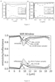
- optical properties of soda lime glass and low-iron glass are compared.
- the thickness of the glass sheets used for these measurements was 2 mm.
- a UV-Visible-NIR spectroscopy was used for solar spectrum measurements, while Fourier transform infrared (FTIR) spectroscopy was used for MIR spectrum measurements. In both cases an integrating sphere was used to capture both specular and diffuse radiation. This setup was also used for the measurements of later Figures.
- Graph a shows the transmission T/ absorption A of a comparable glass sheet made from soda lime and low-iron glass. Transmission is measured as the amount of incident light that passes through the glass sheet. No reflective layer or modified front surface is provided in this instance. As shown in graph a), low-iron glass has a greater transmission than soda lime glass across the range of solar spectrum wavelengths, particularly for visible and NIR wavelengths.
- Graph b shows the reflectance R/absorptance A of comparable soda lime and low-iron glass sheets. Reflectance is measured as the amount of incident light that is reflected from the glass sheet. In this case, a layer of silver was deposited onto the rear surface of the glass sheet. This reflective layer changes the glass sheet from being highly transmissive (as shown in graph a) to highly reflective. As shown in graph b), low-iron glass has a greater reflectance than soda lime glass across the range of solar spectrum wavelengths, particularly for visible and NIR wavelengths.
- the greater transmission/reflectance enabled by low-iron glass results in less solar radiation being absorbed by the glass sheet, which may mean that low-iron glass is preferable for use in radiative cooling units.
- the graph shows the change in the emissivity/reflectance of a low-iron glass sheet for wavelengths in the MIR window as the front surface is sandblasted for different durations (thereby increasing the roughness of the front surface).
- the sandblasting in this instance used general purpose, polydisperse alumina.
- the sandblasting was performed using a Guyson manual blasting cabinet, with the glass being moved relative to the blasting nozzle in a figure-of-eight pattern at a distance of approximately 10 to 20 cm.
- Sandblasting may alternatively be performed using an automated or semi-automated process (i.e., a process at least partially controlled via computer).
- the sandblasting may be performed using any commercially available blasting cabinet; this may be dependent on the blasting parameters required and the dimensions of the glass sheet.
- the emissivity, ⁇ of a clear sample (i.e., a glass sheet not subjected to sandblasting) at approximately 10.5 ⁇ m is 0.83.
- the emissivity is enhanced to 0.88.
- the emissivity is further enhanced to 0.92.
- the emissivity of the sample is increased via sandblasting for all wavelengths across the MIR range, which may enable more effective radiative cooling.
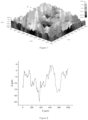
- FIG. 7 and 8 the surface profile of a sandblasted glass surface is shown.
- the surface profile characterisation was performed using an optical microscope and a profilometer. The surface profile was taken across a length of ⁇ 1 mm, using a speed of 200 ⁇ m/s and a sampling frequency of 200 Hz. From the surface profile measurements shown in Figure 7 , a line profile was taken along the X axis, as shown in Figure 8 .
- the root mean square (RMS) deviation was found to be 6.26 ⁇ m.
- the autocorrelation length, ⁇ was found to be 62 ⁇ m.
- the emissivity of a glass sheet may be enhanced by disposing a low-index, low-absorption coating to the front surface of the glass sheet.
- the graph shows that a thin-film of BaF 2 applied to the front surface of the glass sheet can increase emissivity in the MIR range. Emissivity is dependent on the thickness of the coating, but an approximately 1 ⁇ m thick BaF 2 film can enhance the emissivity of the glass sheet to approximately 0.91.
- a thickness of ⁇ 1 ⁇ m may be preferable for BaF 2 , but other thicknesses may be used/may be optimal for other materials.
- Such a coating may provide for similar emissivity enhancement as a roughened surface (as shown in Figure 6 ), but without creating a hazy appearance.
- the measurements of Figure 9 were taken at 10 ⁇ m (in the middle of the MIR window).
- the transmissivity T/reflectance R are shown for a radiative cooling unit wherein the reflective layer disposed on the rear surface of the glass sheet comprises an ultra-thin ( ⁇ 10 nm) silver layer.
- the graph shows that when an ultra-thin reflective layer is used, transmittance of light in the solar spectrum range (particularly for visible wavelengths) through the radiative cooling unit may be significant. Transmissivity of certain visible wavelengths may be approximately 0.2. Similar transmissivity may be achieved by replacing the metallic reflective layer with alternating layers of high and low refractive index layers (for example, Si 3 N 4 and BaF 2 ).
- the thin-film front surface discussed with reference to Figure 9 may be used in addition to the ultra-thin/stacked reflective layer(s) discussed above to provide a non-hazy, partially transparent radiative cooling unit.
- the radiative cooling unit is capable of providing a net cooling power (measured in W/m 2 ) until a maximum temperature difference is created between ambient temperature, T amb , and the temperature of the thermal cooling unit T dev . Once this maximum temperature difference is reached, the net cooling power is 0 W/m 2 , and T dev cannot be further reduced via radiative cooling.
- the radiative cooling unit of the present invention may be able to achieve a cooling of 11°C below ambient in the daytime and 15°C below ambient at night-time.
- U refers to the thermal transmittance value of the glass sheet. Use of a low U value glass may be desirable as this may provide more effective cooling.
- the radiative cooling system comprises one or more radiative cooling units 100 and a heat exchanger 16.
- a cooling loop 12 is fluidly coupled to the radiative cooling units 100 and the heat exchange 16 and configured to carry a cooling fluid (for example, water) between the radiative cooling unit 100 and the heat exchanger 16.
- the cooling fluid may be pumped around the cooling loop 12 by a pump 14.
- the one or more radiative cooling units 100 may each be a radiative cooling unit as discussed above (e.g., as shown in Figure 4 ).
- the heat exchanger 16 transfers heat to the cooling fluid.
- the cooling loop comprises a hot side 12a, configured to transfer the heated cooling fluid to the radiative cooling unit 100, whereat heat is then emitted via radiative cooling.
- the cooling loop comprises a cold side 12b configured to transfer the cooled cooling fluid back to the heat exchanger 16. This process allows for thermal energy to be transferred from the heat exchanger 16 the radiative heat unit 100, thereby removing thermal energy from heat exchanger 16 via passive cooling.
- a refrigeration loop 18 may be provided as an input to the heat exchanger 16.
- the refrigeration loop may carry a refrigerant fluid and may be coupled to an evaporator 20, a compressor 22 and a condenser 24, for example.
- the refrigerant loop 18 may be configured to remove thermal energy from an enclosed volume (for example, a room or a vehicle compartment).
- the radiative cooling unit 100 is used by itself (for example, as a window), thermal energy may be removed from the area surrounding the radiative cooling unit 100 (e.g., thermal energy is transferred from the walls and air surrounding the radiative cooling unit 100).
- the system 10 may allow for the enclosed volume to be remote from the radiative cooling unit 100 and still be cooled via radiative cooling.
- the enclosed volume could be a room within a building while the radiative cooling unit 100 could be situated atop a roof.
- the cooling loop 12a,b and refrigerant loop 18 may enable the room and the radiative cooling unit 100 to be thermally coupled, thereby enabling thermal energy to be removed from the remote volume and emitted at the radiative cooling unit 100.
- a portion of the cooling loop 12a,b may be located in close proximity to the radiative cooling unit 100 to enable efficient heat transfer.
- the cooling loop 12a may comprise a series of coils in contact with a rear surface of the radiative cooling unit 100.
Landscapes
- Chemical & Material Sciences (AREA)
- Engineering & Computer Science (AREA)
- General Chemical & Material Sciences (AREA)
- Life Sciences & Earth Sciences (AREA)
- Chemical Kinetics & Catalysis (AREA)
- Geochemistry & Mineralogy (AREA)
- Materials Engineering (AREA)
- Organic Chemistry (AREA)
- Mechanical Engineering (AREA)
- Optics & Photonics (AREA)
- Health & Medical Sciences (AREA)
- Toxicology (AREA)
- Physics & Mathematics (AREA)
- Surface Treatment Of Glass (AREA)
- Laminated Bodies (AREA)
Abstract
A radiative cooling unit (100) comprising: a glass sheet (110) having a low-absorption for wavelengths in the solar spectrum, the glass sheet (110) comprising a rear surface (114) and a modified front surface (112), the modified front surface having a random surface roughness; and a reflective layer (130) disposed on the rear surface (114) of the glass sheet (110).
Description
- The present invention relates to systems for radiative cooling and methods of producing such systems.
- Radiative cooling is a technology that is widely sought after and promises numerous advantages. By utilising materials to passively radiate thermal energy, rather than relying upon active cooling (i.e., techniques that require a power supply, such as conventional refrigeration or air-conditioning), radiative cooling can provide an efficient and reliable method of cooling buildings, vehicles, devices, etc. Incorporation of radiative cooling units into buildings, for example, may allow for a reduction in buildings' energy consumption while still providing sufficient cooling.
- However, current radiative cooling technologies have a number of limitations. Soda lime-based glass (the most commonly manufactured glass) is not typically suitable for radiative cooling purposes. Relatively high absorption of solar energy and sub-optimal emissivity of infrared (IR) wavelengths mean that glass usually heats, rather than providing cooling.
- Current glass-based radiative cooling devices typically rely upon specialist manufacturing methods and/or composite materials. These methods often require precise creation of nano-scale structures on substrates by using, for example, methods such as nanoprinting/lithography or transference of the structures using intermediate moulds. Otherwise, films, coatings and paints may be applied to substrates, often requiring non-conventional materials (for example, organic or polymer-based films) and/or layers to be carefully deposited and arranged. Such methods and materials mean that radiative cooling devices are relatively difficult and expensive to produce. Current technologies may also be limited in their application, as delicate nano-scale structures and coatings may not be suitable for use in certain conditions and climates due to their lack of durability.
- Although radiative cooling has advanced significantly in recent decades, current limitations mean that the technology has not yet been -widely adopted and further improvements are desirable.
- According to a first aspect of the present invention, there is provided a radiative cooling unit comprising a glass sheet having a low-absorption for wavelengths in the solar spectrum, the glass sheet comprising a rear surface and a modified front surface, the modified front surface having a random surface roughness.
- The solar spectrum may be regarded as an electromagnetic (EM) spectrum indicative of the EM radiation transmitted from the Sun and/or the extra-terrestrial radiation received on Earth. The solar spectrum may be represented by a model such as the AM1.5 spectrum, for example. When considering such solar radiation, wavelengths in the ultraviolet (UV), visible and near-infrared (NIR) spectra (for example, approximately 300 - 2500 nm) may be of particular importance, given that these wavelengths make up the majority of solar irradiance.
- Low-absorption may correspond to an absorbance of less than 0.15, 0.1 or 0.05 for all wavelengths in the visible and NIR range, or the 300 - 2500 nm range, for example (or an average absorbance of less than 0.15, 0.1 or 0.05 over the wavelength range 300 - 2500 nm). Low-absorption may correspond to overall absorption of less than 15%, 10% or 5% of energy received in the solar spectrum/energy received from the Sun.
- Use of a modified glass sheet may provide numerous advantages over existing radiative cooling technologies. The modified front surface of the glass sheet may be stronger, more durable and/or more chemically insert than polymer films or coatings. This may reduce the likelihood of damage to the modified front surface, which may allow the radiative heat unit to retain its desirable properties for a longer duration when in use (thereby extending the lifespan of the unit or reducing the need for maintenance/repair). Repair of the radiative cooling unit may also be easier and less costly; the roughness may be readily restored. rather than having to reapply coatings or films.
- Glass is also a cheap, widely manufactured material. The use of a modified glass sheet may therefore result in a cheaper radiative cooling unit compared to composite materials. Glass may provide better insulating properties than paints or coatings. A glass-based radiative cooling unit may be easily recyclable and/or manufactured using recycled materials, as glass has a well-developed recycling process. Plastic films and coatings may require more specialised recycling processes.
- The radiative cooling unit further comprises a reflective layer disposed on the rear surface of the glass sheet. The reflective layer may be configured to reflect at least 90% of solar energy incident on the radiative cooling unit. The reflective layer be configured to have a reflectance of 0.9 or 0.95 for all wavelengths in the 300 - 2500 nm range, for example. The reflective layer may also be easily recyclable; well-developed recycling processes exist for metals (for example, silver).
- The random surface roughness of the modified front surface may be configured to enhance the emissivity of the glass sheet in the range of 8 - 13 µm. The 8 - 13 µm range may be regarded as the 'mid-infrared (MIR) window', wherein Earth's atmosphere is substantially transparent.
- An enhanced emissivity may be regarded as the glass sheet having a minimum emissivity of at least 0.75, 0.8 or 0.85 for wavelengths in the 8 - 13 µm range (or an average emissivity of at least 0.75, 0.8 or 0.85 over the wavelength range 8 - 13 µm). Enhancing the emissivity of a glass sheet may correspond to the emissivity of the glass sheet being increased by any amount. There may be an increase in emissivity of at least 0.01, 0.05 or 0.1 compared to an unmodified glass sheet of the same material. Emissivity may be increased for all or some wavelengths in the 8 - 13 µm range, or a subset of said range. For example, emissivity may be increased by approximately 0.1 in the range of 9 to 11 µm, and increased by a lesser amount outside of this range. Where the glass sheet has a particularly low emissivity at certain wavelengths (which may approximately 10 µm for soda lime), the emissivity may be increased at these wavelengths by a greater amount such that the emissivity is 'flatter' across the MIR window.
- Random surface roughness may be regarded as the surface having a roughened, textured surface (compared to typical glass sheets) wherein the texture does not have any distinguishable, repeating structure. The modified front surface may be 'textured' but not comprise any ridges, protrusions, etc. with a repeating pattern. The texture may be regarded as having a granular structure.
- The roughness of the modified front surface may be characterised by a height error/deviation (for example, root mean square error) and an autocorrelation length. The roughness of the modified front surface may have a standard deviation of height of less than 20 µm. The roughness may have a standard deviation of at least 2µm. Sufficient emissivity may be achieved with roughness having a standard deviation between 1 µm and 20 µm, or between 2 µm and 10 µm. The roughness may have an autocorrelation length of less than 100 µm or between 20 µm and 200 µm (or between 30 µm and 100 µm).
- The roughness of the modified front surface may be measured using any suitable means. Profilometers capable of measuring surface roughness with sub-micrometre accuracy are commercially available. Profilometers may be contact/forced based or optical based. Other methods may equally be used to measure/characterise the surface of the modified sheet, such as atomic force microscopy, from which the deviation and autocorrelation length can be determined.
- The glass sheet may comprise a low-iron glass material. The glass sheet may be made from a single sheet of the low-iron glass material. The low-iron glass material may have a ferric oxide (i.e., iron oxide) content of less than 0.01% by mass.
- The low-iron glass material may be Pilkington Optiwhite™, for example. The low-iron glass material may be of a quality (e.g., having a manufacturing precision/tolerance and a transparency) such that it would be suitable for solar panel or optical display applications.
- The glass sheet may have a thickness of less than 2 mm or less than 1 mm. The thickness of the glass sheet may be configured for a desired compromise between optical and mechanical properties, for example. This may be dependent on the application of the radiative cooling unit. For example, a thickness of approximately 1 mm may enable a lightweight unit with minimal absorption of solar energy, while still being durable enough that the radiative cooling unit could be used outside (e.g., mounted to a building).
- The glass sheet may have a thickness of ≤ 500 µm. The glass sheet may have a thickness of 100 µm or 200 µm, for example. Glass sheets with thicknesses significantly less than 1 mm may be regarded as 'ultra-thin'.
- The use of an ultra-thin glass sheet may enable the radiative cooling unit to be flexible (i.e., the radiative cooling may be deformable and/or conformed to a curved surface). The use of an ultra-thin glass sheet may allow the glass sheet to be 'low-absorption' even where the glass sheet is not made from a low-iron glass material. I.e., the ultra-thin glass sheet may comprise a material with a ferric oxide content of 0.01% by mass or greater, while still providing sufficiently low absorption of solar energy that the radiative cooling unit is not heated excessively. The glass sheet may comprise Corning® Willow® glass, for example.
- The reflective layer may comprise a metallic layer deposited on the rear surface of the glass sheet. The metallic layer may be deposited onto the rear surface of the glass using, for example, physical vapour deposition (PVD) or chemical vapour deposition (CVD). The metallic layer may comprise silver or aluminium or another reflective metal.
- The reflective layer may be configured to reflect at least 90% or 95% of energy in the solar spectrum incident on the radiative cooling unit at the front surface. The reflective layer may have a transmittance of less than 0.1 or less than 0.05 for wavelengths in the 300 - 2500 nm range (or an average transmittance of less than 0.1 or 0.05 over the wavelength range 300 - 2500 nm).
- The metallic layer may have a thickness of 200 nm or less. The thickness of the metallic layer may be configured such that the radiative cooling unit is substantially opaque to solar wavelengths (e.g., a transmittance or average transmittance of less than 0.1 or less than 0.05 for wavelengths in the solar spectrum, particularly 300 - 2500 nm). The required thickness to achieve a desired opacity may be dependent on the metal used. The metallic layer may have a thickness of 100 nm, 150 nm or 200 nm. The metallic layer may be thicker than 200 nm where the thickness is not a crucial design factor. Where the reflective layer is preferably substantially opaque (i.e., transmittance or average transmittance of 0.01 or ~ 0 for solar wavelengths), the metallic layer may be 300 nm, 500 nm. 1 µm or greater in thickness.
- The metallic layer may have a thickness of 10 nm or less. The thickness of the metallic layer may be configured such that the radiative cooling unit is at least partially transmissive to solar wavelengths, particularly in the visible range (e.g., a transmittance of approximately 0.1 or 0.2). This may allow the radiative cooling unit to be used in applications where some transparency is desirable, for example in architectural or automotive windows.
- The reflective layer may comprise a diffuse solar reflector. The diffuse solar reflector may be configured to diffusely reflect at least 90% or 95% of the solar spectrum energy incident on the radiative cooling unit.
- The diffuse solar reflector may comprise a polymer material with a high diffuse reflectance (at least 95% or at least 99%) in the visible and NIR range. The diffuse solar reflector may comprise Spectralon or other similar fluoropolymers, for example. The diffuse reflector material may comprise other types of high-reflectance/low-absorption polymer materials, for example polyethylene or polysiloxanes. The diffuse reflector material may have a porous structure, such that a substantial proportion of incoming light is back scattered. The diffuse reflector material may be deposited directly onto the rear surface of the glass sheet (using any suitable deposition technique). Alternatively, the diffuse solar reflector may be a separate component (for example, a diffuse reflector material deposited onto a substrate). The solar reflector may be affixed to the rear surface of the glass sheet using any suitable mechanical means or an adhesive.
- The reflective layer may comprise a plurality of layers comprising at least two materials, the two materials having different refractive indices, wherein the plurality of layers comprises alternating layers of the two materials (the reflective layer may be configured as a Bragg mirror). At least one layer of each material may be provided. The plurality of layers may comprise at least one layer of high refractive index material and at least one layer of low refractive index material (for wavelengths in the solar spectrum). The plurality of layers may comprise Si3N4 and BaF2, for example. Similar to the use of an ultra-thin metallic layer (10 nm or less), the layered reflective layer may enable the radiative cooling unit to be at least partially transmissive to wavelengths in the solar spectrum or at least the visible range.
- The radiative cooling unit may further comprise a protective layer disposed on a back side of the reflective layer. The protective layer may comprise an additional glass layer or a polymer layer disposed on the rear side of the reflective layer. The protective layer may be laminated on to the rear side of the reflective layer. The protective layer may reduce the likelihood of damage to the reflective layer.
- The radiative cooling unit may further comprise a colour layer configured to impart a visible colour to light reflected from the radiative cooling unit. This may give the glass of the cooling unit a coloured appearance (whereas the radiative cooling unit may otherwise have a diffuse white appearance). The colour layer may be disposed on a front surface of the reflective layer and/or on the rear surface of the glass sheet. The colour sheet may be sandwiched between the reflective layer and the rear surface of the glass sheet when the radiative cooling unit is assembled. This may reduce the likelihood of the colour laying being damaged and/or prevent interference with the modified front surface of the glass sheet. Alternatively, the colour layer may be disposed on the front surface of the glass sheet. The colour layer may be disposed on top of the modified front surface of the glass sheet. Modification of the front surface of the glass sheet may comprise modification of the colour layer - i.e., the colour layer at the front surface of the glass sheet may be roughened, rather than the glass sheet itself.
- The colour layer may comprise any transparent/translucent material that will result in reflected light being coloured. The colour layer may comprise a transparent polymer layer (for example, PMMA, PDMS, polycarbonate or polyethylene). The polymer layer may be between 1 and 200 microns, or 2 and 100 microns. The colour layer may comprise a fluorescent material. The fluorescent material may be mixed into or disposed on the polymer layer. The fluorescent material may comprise a fluorescent dye or quantum dots, for example. The fluorescent material may be configured to absorb part of the solar radiation (e.g., UV light) and emit this at a different wavelength. The fluorescent material may fluoresce at a visible wavelength (e.g., green, red or blue), thereby resulting in the overall light reflected from the cooling unit having a corresponding colour - i.e., colour is 'added' to the reflected visible spectrum. The colour layer may comprise non-fluorescent paints/pigments. The use of fluorescent materials to generate a coloured appearance may be preferable to using non-fluorescent materials or coloured glass. Said materials generate colour by absorbing certain visible wavelengths -i.e., 'taking' certain colours from the reflected visible spectrum. Using non-fluorescent materials may reduce the thermal performance of the radiative cooling unit.
- According to a second aspect of the present invention, there is provided a method of producing a radiative cooling unit, the method comprising:
- providing a glass sheet having a low-absorption for wavelengths in the solar spectrum, the glass sheet comprising a rear surface and a front surface;
- modifying the front surface of the glass sheet to produce a modified front surface having a random surface roughness; and
- applying a reflective layer to the rear surface of the glass sheet.
- The method may be used to produce a radiative cooling unit according to the first aspect.
- Modifying the front surface of the glass sheet may comprise mechanical abrasion. The front surface of the glass sheet may be sandblasted, for example. 'Sandblasting' may comprise spraying the front surface with any suitable abrasive (such as grit, metallic particles, ceramic particles, etc.) and not necessarily sand. Alternatively, mechanical abrasion may comprise sanding the front surface. Similar to above, 'sanding' may comprise using any suitable abrasive material (for example, wire wool) and not necessarily sandpaper. Sanding may be done with a sheet of abrasive material or with a belt or disk sander, for example. Any suitable process by which the front surface is roughened may be used. The front surface may be sandblasted (or otherwise abraded) to achieve a desired emissivity of the glass sheet in the 8 - 13 µm range. The desired emissivity may be achieved by controlling the pressure of a blasting fluid, the abrasiveness of an abrasive material and/or the blasting duration, for example.
- Sandblasting may be performed with a polydisperse abrasive (e.g., polydisperse alumina) having a relatively large range of grit sizes, for example 60 to 80 grit (approximately 250 to 160 microns). Commercially available polydisperse alumina may be available with grit sizes in the range of 40 (approximately 400 microns) to microfine grit size 1200 (approximately 4.5 microns). An abrasive with a grit size of between 240 and 800 may be used (corresponding to particle sizes between 53.5 and 9.8 microns). The abrasive may have a grit size of 500 (approximately 16 to 20 microns particle size). The particle size may be an average particle size. The average particle size may be determined/verified via test sieves.
- The sandblasting may be performed in a pattern across the glass sheet, so as to cover the whole sheet and to generate a uniform, random roughness. The sandblasting may be performed in figure-of-eight pattern, for example, which may reduce the formation of long-range repeating structures (for example, lines or swirls associated with a linear or circular blasting pattern). The glass sheet may be held by a user and then moved under the sandblasting nozzle manually (or vice versa), or the nozzle may be scanned electronically/mechanically over the glass sheet. The nozzle of the sandblasting apparatus may be positioned approximately 10 to 20 cm or 5 to 30 cm away from the glass sheet.
- The size of the grit, the distance from the nozzle and the time duration of sandblasting may all be parameters that are varied/selected in order to achieve a desired roughness.
- Modifying the front surface of the glass sheet may comprise chemical etching. An acid, for example hydrofluoric acid, may be applied to the front surface of the glass sheet. Parameters of the chemical etching (e.g., acid strength/concentration, duration, etc.) may be controlled to achieve a desired emissivity of the glass sheet.
- Modifying the front surface of the glass sheet may comprise laser ablation. A laser may be scanned across the surface of the glass sheet in order to generate the desired surface roughness. The power and/or pulse duration may be controlled in order to produce a desirable ablation. The laser may have a pulse length of less than 1 microsecond, or less than 500 nanoseconds, or less than 100 nanoseconds, for example. Short laser pulses may be used to produce the desired micron-sized features of the modified surface.
- Mechanical abrasion, chemical etching or laser ablation may provide for an easier and/or cheaper method of manufacturing radiant cooling units, compared to methods of the prior art. Sandblasting and acid etching are both established techniques that are used extensively in the glass-making industry. Using these techniques to produce the modified front surface may be preferable to lithographic or nanoprinting-based techniques, or use of other materials (for example, applying separate films to the glass).
- According to a third aspect of the present invention, there is provided a radiative cooling unit comprising a glass sheet having a low-absorption for wavelengths in the solar spectrum, the glass sheet comprising a rear surface and a front surface. The radiative cooling unit further comprises a reflective layer disposed on the rear surface of the glass sheet. Where applicable, the radiative cooling unit may have similar features to the first aspect (e.g., similar glass sheet and/or reflective layer properties).
- The radiative cooling unit further comprises a film disposed on the front surface of the glass sheet; the film configured to enhance the emissivity of the glass sheet in the range of 8 to 13 µm. An enhanced emissivity may be regarded as the film/glass sheet having a minimum emissivity of at least 0.75, 0.8 or 0.85 for wavelengths in the 8 - 13 µm range (or an average emissivity of at least than 0.75, 0.8 or 0.85 over the wavelength range 8 - 13 µm). Enhancing the emissivity of a glass sheet may correspond to the emissivity of the glass sheet being increased by any amount. There may be an increase in emissivity of at least 0.01, 0.05 or 0.1 compared to glass sheet without a film or coating. Emissivity may be increased for all or some wavelengths in the 8 - 13 µm range, or a subset of said range. For example, emissivity may be increased by approximately 0.1 in the range of 9 to 1 1 µm, and increased by a lesser amount outside of this range. Where the glass sheet has a particularly low emissivity at certain wavelengths (which may approximately 10 µm for soda lime), the emissivity may be increased at these wavelengths by a greater amount such that the emissivity is 'flatter' across the MIR window.
- The film may comprise a thin film (approximately 1 µm in thickness) of low-index, low-absorption (at solar spectrum wavelengths) material. The film may comprise at least one of MgF2, CaF2 or BaF2, for example.
- Use of a film on the front surface of the glass sheet (rather than modifying the front surface to have a random surface roughness) may be beneficial for certain applications. The use of a film may provide the same benefits discussed for the radiative cooling unit of the first aspect, without producing a hazy or 'frosted' appearance. This may be beneficial where the radiative cooling unit is at least partial transmissive (the modified textured front surface may reduce transmission of visible light through the glass sheet) or where a polished, mirrored appearance is desired.
- According to a fourth aspect of the present invention, there is provided a radiative cooling system comprising one or more radiative cooling units according to the first or third aspect.
- The radiative cooling system may further comprise a heat exchanger and a cooling loop fluidly coupled to the one or more radiative cooling units and the heat exchanger, the cooling loop configured to transport a cooling fluid from the heat exchanger to the one or more radiative cooling units. The radiative cooling system may enable heat to be transferred from a remote location that is not necessarily adjacent to the radiative cooling units (via the heat exchanger and cooling loop) where energy can be emitted, thereby cooling the remote location.
- Embodiments of the invention will be described, purely by way of example, with reference to the accompanying drawings, in which:
-
Figure 1 is a graph depicting the wavelengths associated with solar radiation, ambient blackbody radiation and atmospheric emissivity; -
Figure 2 is a simplified diagram of heat transfer processes during radiative cooling; -
Figure 3 comprises graphs depicting absorption and emissivity properties of soda lime glass; -
Figure 4 is a schematic diagram of an example radiative cooling unit; -
Figure 5 comprises graphs depicting transmission and reflectance properties of an example glass sheet; -
Figure 6 is a graph depicting the effect of sandblasting on the emissivity of a glass sheet/radiative cooling unit; -
Figure 7 is a profilometry plot of a sandblasted glass surface; -
Figure 8 is a graph depicting the surface profile of a sandblasted glass surface; -
Figure 9 is a graph depicting the variation of glass sheet/radiative cooling unit emissivity as a function of the thickness of a thin-film; -
Figure 10 is a graph depicting transmission and reflectance properties of a glass sheet/radiative cooling unit; -
Figure 11 is a graph depicting the net cooling power of a radiative cooling unit; and -
Figure 12 is a schematic diagram of an example radiative cooling system. - Like features of the various figures shall be donated with the same reference numerals.
- Referring to
Figure 1 , the graph shows the solar radiation spectrum (irradiance, I AM1.5, as a function of wavelength, λ), the emissivity spectrum of the Earth's atmosphere (emissivity, εatm , as a function of wavelength, λ), and the spectrum emitted by an ideal blackbody at 300 K (irradiance, IBB , as a function of wavelength, λ). - In this graph, the solar spectrum is modelled using the Air Model (AM) 1.5 to represent solar radiation received on Earth. The AM 1.5 model is widely used for characterising solar panel performance.
- As shown in
Figure 1 , there is little or no overlap between the solar spectrum (wherein the vast majority of energy is transmitted at ultraviolet (UV), visible and near-infrared (NIR) wavelengths; approximately 300 - 2500 nm) and the emission spectrum of a blackbody at 300 K (wherein the vast majority of energy is emitted at wavelengths greater than 3 µm). A significant amount of the energy emitted by the blackbody is in the 8 - 13 µm range. This region is known as the 'mid-infrared (MIR) window', as the Earth's atmosphere is substantially transparent to MIR wavelengths. - Radiative cooling may be enabled by providing a material that is substantially transparent to solar wavelengths of 300 - 2500 nm and has a high emissivity for MIR wavelengths of 8 - 13 µm. Such a material would reduce the amount of solar energy absorbed by a radiative cooling unit while maximising the amount of energy emitted into space in the MIR window via blackbody radiation.
- Referring to
Figure 2 , an illustration of a simplified radiative cooling process is shown. The diagram shows the main heat transfer mechanisms associated with radiative cooling. In this example, aradiative cooling unit 100 is mounted to a roof of abuilding 101. - Energy can be transferred to the
radiative cooling unit 100 from a number of external sources. Incoming energy is transferred to the radiative cooling unit via electromagnetic (EM) radiation transmitted directly from the Sun or reflected off of the atmosphere, with heat transfer rates of q̇sun and q̇atm respectively. Some energy may also be transferred to theheat transfer unit 100 via parasitic sources (such as convection and conduction from the surrounding atmosphere), with a heat transfer rate of q̇par. - Outgoing energy is transmitted from the
radiative cooling unit 100 via blackbody radiation, with a heat transfer rate of q̇cool.Theradiative cooling unit 100 will have a natural blackbody radiation temperature (ambient temperature of approximately 300 K). Theradiative cooling unit 100 will reach an equilibrium temperature, which will depend on the temperature of the environment surrounding theunit 100, the solar radiation energy absorbed and heat exchanges with other surrounding objects (such as thehouse 101 structure to which theunit 100 is coupled). As theradiative cooling unit 100 radiates energy, energy will be transferred to theradiative cooling unit 100 from the surrounding ambient environment, thereby providing passive cooling of thehouse 101. - For the
radiative cooling unit 100 to cool thehouse 101, the outgoing energy transfer much be greater than the incoming energy transfer. I.e.,
- This can be achieved by maximising emission of energy from the radiative cooling unit 100 (i.e., increasing the emissivity of the unit, particularly in the MIR wavelength range where energy can be efficiently radiated into outer space) and/or reducing the absorption of solar energy. The
radiative cooling unit 100 may reflect a substantial amount of solar spectrum energy in order to reduce the amount of energy absorbed by theradiative cooling unit 100 and thehouse 101. - If the condition in
equation 1 is satisfied, radiative cooling can provide a means of passive cooling. No energy is required to provide the cooling effect; instead, the cooling results from the selective reflectance/emittance of the solar and blackbody wavelengths shown inFigure 1 . An ideal radiative cooling unit would have an emissivity of ~ 1 for wavelengths in the MIR window and a reflectivity of ~ 1 for all other wavelengths (particularly wavelengths in the solar spectrum). - With reference to
Figure 3 , optical properties of a soda lime-based glass sheet are shown. Soda lime glass is widely used in conventional applications. - Graph a) shows that although soda lime-based glass is 'transparent', a significant amount of energy in the solar spectrum is absorbed. Soda lime absorption (Asoda lime) of visible/NIR wavelengths may be as high as ~ 0.2, for example. Absorption of solar radiation, proportional to q̇sun in
equation 1, will therefore be increased, reducing the cooling effect provided by the unit. Graph b) shows that soda lime also has a sub-optimal emissivity for MIR wavelengths, which may be as low as ~ 0.7 in the MIR window. - These two properties of soda lime glass may make conventional glass sheets unsuitable for radiative cooling purposes; the requirement in
equation 1 may not be met. Polished glass surfaces may instead act as a heat mirror, actively heating an underlying structure by 'trapping' heat via a greenhouse effect. - Referring to
Figure 4 , a schematic diagram of aradiative cooling unit 100 is shown. Theradiative cooling unit 100 comprises aglass sheet 110, the glass sheet having afront surface 112 and arear surface 114. - The
radiative cooling unit 100 comprises a modifiedfront surface 120. The modifiedfront surface 120 has a random surface roughness. The modifiedfront surface 120 may be manufactured by, for example, sandblasting, acid etching or laser ablating thefront surface 112 of theglass sheet 110. - Alternatively, the modified
front surface 120 may instead be a separate component, such as a thin-film or a coating that is applied to/deposited on thefront surface 112 of the glass sheet. - The
radiative cooling unit 100 further comprises areflective layer 130 disposed on therear surface 114 of theglass sheet 110. Thereflective layer 130 may comprise a metal mirror that is deposited onto therear surface 114 or a diffuse reflector material. A protective layer 140 (for example a glass or polymer layer) may be disposed on a rear surface of thereflective layer 130, though this is not essential to the radiative cooling effects of theunit 100. A colour layer 150 (e.g., a polymer layer comprising a fluorescent material or quantum dots) may be sandwiched between theglass sheet 110 and thereflective layer 130, though this is not essential to the radiative cooling effects of theunit 100. Thecolour layer 150 is configured to provide theradiative cooling unit 100 with a coloured appearance (e.g., red, green or blue). The colour layer may comprise a transparent polymer layer (for example, PMMA, PDMS, polycarbonate or polyethylene). The colour layer may comprise a fluorescent material mixed into or disposed on the polymer layer (e.g. a fluorescent dye or quantum dots, for example). The fluorescent material absorbs part of the solar radiation (e.g., UV light) and emits at a different wavelength. The fluorescent material may fluoresce at a visible wavelength (e.g., green, red or blue), thereby resulting in the overall light reflected from the cooling unit having a corresponding colour - i.e., colour is 'added' to the reflected visible spectrum. - The
glass sheet 110 has a low absorbance for solar spectrum wavelengths. Theglass sheet 110 may be made from low-iron glass. Alternatively, or additionally, the thickness of theglass sheet 110, dglass , may be thin enough that absorption of solar radiation is minimal. A significant proportion (for example, 90% or more) of incomingsolar radiation 102 may be transmitted through theglass sheet 110, being reflected from thereflective surface 130. - In certain applications of the
radiative cooling unit 100, thereflective layer 130 may be omitted, may be made ultra-thin (for example, a thickness dref of approximately 10 nm or less), or may be replaced by a semi-reflective film. In such examples, a portion of the incomingsolar radiation 102 may be transmitted through theradiative cooling unit 100 to the rear side (i.e., pass through theglass sheet 110 rather than being reflected), making theradiative cooling unit 100 partially-transparent. - The modified front layer 120 (or equally, the thin-film/coating applied to the front surface 112) enhances the emissivity of the glass sheet for MIR wavelengths (particularly 8 - 13 µm). A substantial portion of
incoming MIR radiation 104 may be absorbed by the glass sheet and subsequently emitted. Theglass sheet 110 will similarly emit a substantial proportion of blackbody radiation (of which a significant portion will be in the MIR window range of 8 - 13 µm for ambient objects of ~ 300 K). This enables theradiative cooling unit 100 to emit thermal energy that has been absorbed from the surrounding environment and/or underlying structures, thereby cooling said environment/structures. - The
radiative cooling unit 100 is shown inFigure 4 as a standalone component. However, this unit, including the variations discussed above, may be incorporated into a wide range of applications. Theradiative cooling unit 100 ofFigure 4 could be applied to buildings to provide cooling, either on the walls or on the roof (similar to a solar panel array). Where theradiative cooling unit 100 is at least partially transparent, this may allow it to be used as a window in buildings or vehicles, for example. Where theglass sheet 110 is ultra-thin, theradiative cooling unit 100 may be flexible, thereby allowing it to be used in further applications wherein the sheet may be bent or deformed (the radiative cooling unit could be incorporated applied to a curved surface, for example). - Referring to
Figure 5 , optical properties of soda lime glass and low-iron glass are compared. The thickness of the glass sheets used for these measurements was 2 mm. A UV-Visible-NIR spectroscopy was used for solar spectrum measurements, while Fourier transform infrared (FTIR) spectroscopy was used for MIR spectrum measurements. In both cases an integrating sphere was used to capture both specular and diffuse radiation. This setup was also used for the measurements of later Figures. - Graph a) shows the transmission T/ absorption A of a comparable glass sheet made from soda lime and low-iron glass. Transmission is measured as the amount of incident light that passes through the glass sheet. No reflective layer or modified front surface is provided in this instance. As shown in graph a), low-iron glass has a greater transmission than soda lime glass across the range of solar spectrum wavelengths, particularly for visible and NIR wavelengths.
- Graph b) shows the reflectance R/absorptance A of comparable soda lime and low-iron glass sheets. Reflectance is measured as the amount of incident light that is reflected from the glass sheet. In this case, a layer of silver was deposited onto the rear surface of the glass sheet. This reflective layer changes the glass sheet from being highly transmissive (as shown in graph a) to highly reflective. As shown in graph b), low-iron glass has a greater reflectance than soda lime glass across the range of solar spectrum wavelengths, particularly for visible and NIR wavelengths.
- The greater transmission/reflectance enabled by low-iron glass results in less solar radiation being absorbed by the glass sheet, which may mean that low-iron glass is preferable for use in radiative cooling units.
- Referring to
Figure 6 , the effect of modifying the front surface of the glass sheet is illustrated. The graph shows the change in the emissivity/reflectance of a low-iron glass sheet for wavelengths in the MIR window as the front surface is sandblasted for different durations (thereby increasing the roughness of the front surface). - The sandblasting in this instance used general purpose, polydisperse alumina. The sandblasting was performed using a Guyson manual blasting cabinet, with the glass being moved relative to the blasting nozzle in a figure-of-eight pattern at a distance of approximately 10 to 20 cm. Sandblasting may alternatively be performed using an automated or semi-automated process (i.e., a process at least partially controlled via computer). The sandblasting may be performed using any commercially available blasting cabinet; this may be dependent on the blasting parameters required and the dimensions of the glass sheet.
- As shown, the emissivity, ε, of a clear sample (i.e., a glass sheet not subjected to sandblasting) at approximately 10.5 µm is 0.83. When the sample is sandblasted for 20 seconds, the emissivity is enhanced to 0.88. When the sample is sandblasted for 40 seconds, the emissivity is further enhanced to 0.92. The emissivity of the sample is increased via sandblasting for all wavelengths across the MIR range, which may enable more effective radiative cooling.
- Referring to
Figures 7 and 8 , the surface profile of a sandblasted glass surface is shown. The surface profile characterisation was performed using an optical microscope and a profilometer. The surface profile was taken across a length of ~ 1 mm, using a speed of 200 µm/s and a sampling frequency of 200 Hz. From the surface profile measurements shown inFigure 7 , a line profile was taken along the X axis, as shown inFigure 8 . The root mean square (RMS) deviation was found to be 6.26 µm. The autocorrelation length, ξ, was found to be 62 µm. - Referring to
Figure 9 , the emissivity of a glass sheet may be enhanced by disposing a low-index, low-absorption coating to the front surface of the glass sheet. The graph shows that a thin-film of BaF2 applied to the front surface of the glass sheet can increase emissivity in the MIR range. Emissivity is dependent on the thickness of the coating, but an approximately 1 µm thick BaF2 film can enhance the emissivity of the glass sheet to approximately 0.91. A thickness of ~ 1 µm may be preferable for BaF2, but other thicknesses may be used/may be optimal for other materials. Such a coating may provide for similar emissivity enhancement as a roughened surface (as shown inFigure 6 ), but without creating a hazy appearance. The measurements ofFigure 9 were taken at 10 µm (in the middle of the MIR window). - Referring to
Figure 10 , the transmissivity T/reflectance R are shown for a radiative cooling unit wherein the reflective layer disposed on the rear surface of the glass sheet comprises an ultra-thin (≤ 10 nm) silver layer. The graph shows that when an ultra-thin reflective layer is used, transmittance of light in the solar spectrum range (particularly for visible wavelengths) through the radiative cooling unit may be significant. Transmissivity of certain visible wavelengths may be approximately 0.2. Similar transmissivity may be achieved by replacing the metallic reflective layer with alternating layers of high and low refractive index layers (for example, Si3N4 and BaF2). The thin-film front surface discussed with reference toFigure 9 may be used in addition to the ultra-thin/stacked reflective layer(s) discussed above to provide a non-hazy, partially transparent radiative cooling unit. - Referring to
Figure 11 , the radiative cooling effects of a radiative cooling unit according to the present invention are shown. The radiative cooling unit is capable of providing a net cooling power (measured in W/m2) until a maximum temperature difference is created between ambient temperature, Tamb , and the temperature of the thermal cooling unit Tdev. Once this maximum temperature difference is reached, the net cooling power is 0 W/m2, and Tdev cannot be further reduced via radiative cooling. - The radiative cooling unit of the present invention may be able to achieve a cooling of 11°C below ambient in the daytime and 15°C below ambient at night-time. In the graph of
Figure 11 , U refers to the thermal transmittance value of the glass sheet. Use of a low U value glass may be desirable as this may provide more effective cooling. - Referring to
Figure 12 , a schematic diagram of aradiative cooling system 10 is shown. The radiative cooling system comprises one or moreradiative cooling units 100 and aheat exchanger 16. A coolingloop 12 is fluidly coupled to theradiative cooling units 100 and theheat exchange 16 and configured to carry a cooling fluid (for example, water) between theradiative cooling unit 100 and theheat exchanger 16. The cooling fluid may be pumped around thecooling loop 12 by apump 14. The one or moreradiative cooling units 100 may each be a radiative cooling unit as discussed above (e.g., as shown inFigure 4 ). - The
heat exchanger 16 transfers heat to the cooling fluid. The cooling loop comprises ahot side 12a, configured to transfer the heated cooling fluid to theradiative cooling unit 100, whereat heat is then emitted via radiative cooling. The cooling loop comprises acold side 12b configured to transfer the cooled cooling fluid back to theheat exchanger 16. This process allows for thermal energy to be transferred from theheat exchanger 16 theradiative heat unit 100, thereby removing thermal energy fromheat exchanger 16 via passive cooling. - A refrigeration loop 18 (or any other device) may be provided as an input to the
heat exchanger 16. The refrigeration loop may carry a refrigerant fluid and may be coupled to anevaporator 20, acompressor 22 and acondenser 24, for example. Therefrigerant loop 18 may be configured to remove thermal energy from an enclosed volume (for example, a room or a vehicle compartment). - Where the
radiative cooling unit 100 is used by itself (for example, as a window), thermal energy may be removed from the area surrounding the radiative cooling unit 100 (e.g., thermal energy is transferred from the walls and air surrounding the radiative cooling unit 100). However, thesystem 10 may allow for the enclosed volume to be remote from theradiative cooling unit 100 and still be cooled via radiative cooling. For example, the enclosed volume could be a room within a building while theradiative cooling unit 100 could be situated atop a roof. Thecooling loop 12a,b andrefrigerant loop 18 may enable the room and theradiative cooling unit 100 to be thermally coupled, thereby enabling thermal energy to be removed from the remote volume and emitted at theradiative cooling unit 100. - A portion of the
cooling loop 12a,b may be located in close proximity to theradiative cooling unit 100 to enable efficient heat transfer. For example, thecooling loop 12a may comprise a series of coils in contact with a rear surface of theradiative cooling unit 100. - Although specific examples have been described, the skilled person will appreciate that variations are possible, within the scope of the invention, which should be determined with reference to the accompanying claims.
Claims (15)
- A radiative cooling unit comprising:a glass sheet having a low-absorption for wavelengths in the solar spectrum, the glass sheet comprising a rear surface and a modified front surface, the modified front surface having a random surface roughness; anda reflective layer disposed on the rear surface of the glass sheet.
- The radiative cooling unit of claim 1, wherein the random surface roughness of the modified front surface is configured to enhance the emissivity of the glass sheet in the range of 8 - 13 µm.
- The radiative cooling unit of claim 1 or 2, wherein the glass sheet comprises a low-iron glass material.
- The radiative cooling unit of any preceding claim, wherein the glass sheet has a thickness of ≤ 500 µm.
- A radiative cooling unit, comprising:a glass sheet having a low-absorption for wavelengths in the solar spectrum, the glass sheet comprising a rear surface and a front surface;a film disposed on the front surface of the glass sheet, the film configured to enhance the emissivity of the glass sheet in the range of 8 to 13 µm; anda reflective layer disposed on the rear surface of the glass sheet.
- The radiative cooling unit of any preceding claim, wherein the reflective layer comprises a metallic layer deposited on the rear surface of the glass sheet.
- The radiative cooling unit of any preceding claim, wherein the reflective layer is configured to reflect at least 90% of energy in the solar spectrum.
- The radiative cooling unit of claim 6 or claim 7, wherein the metallic layer has a thickness of ≤ 10 nm.
- The radiative cooling unit of any of claims 1 to 5 wherein the reflective layer comprises a diffuse solar reflector.
- The radiative cooling unit of any of claims 1 to 5, wherein the reflective layer comprises a plurality of layers comprising at least two materials, the two materials having different refractive indices, wherein the plurality of layers comprises alternating layers of the two materials.
- The radiative cooling unit of any preceding claim, further comprising a protective layer disposed on a back side of the reflective layer.
- The radiative cooling unit of any preceding claim, further comprising a colour layer configured to impart a visible colour to light reflected from the radiative cooling unit.
- A method of producing a radiative cooling unit, the method comprising:providing a glass sheet having a low-absorption for wavelengths in the solar spectrum, the glass sheet comprising a rear surface and a front surface;modifying the front surface of the glass sheet to produce a modified front surface having a random surface roughness; andapplying a reflective layer to the rear surface of the glass sheet.
- The method of claim 13, wherein:i) modifying the front surface of the glass sheet comprises mechanical abrasion;ii) modifying the front surface of the glass sheet comprises chemical etching; and/oriii) modifying the front surface of the glass sheet comprises laser ablation.
- A radiative cooling system comprising:one or more radiative cooling units according to any of claims 1 to 12;a heat exchanger; anda cooling loop fluidly coupled to the one or more radiative cooling units and the heat exchanger, the cooling loop configured to transport a cooling fluid from the heat exchanger to the one or more radiative cooling units.
Priority Applications (2)
| Application Number | Priority Date | Filing Date | Title |
|---|---|---|---|
| EP23386086.5A EP4520736A1 (en) | 2023-09-07 | 2023-09-07 | Radiative cooling |
| PCT/EP2024/074893 WO2025051894A2 (en) | 2023-09-07 | 2024-09-05 | Radiative cooling |
Applications Claiming Priority (1)
| Application Number | Priority Date | Filing Date | Title |
|---|---|---|---|
| EP23386086.5A EP4520736A1 (en) | 2023-09-07 | 2023-09-07 | Radiative cooling |
Publications (1)
| Publication Number | Publication Date |
|---|---|
| EP4520736A1 true EP4520736A1 (en) | 2025-03-12 |
Family
ID=88098162
Family Applications (1)
| Application Number | Title | Priority Date | Filing Date |
|---|---|---|---|
| EP23386086.5A Pending EP4520736A1 (en) | 2023-09-07 | 2023-09-07 | Radiative cooling |
Country Status (2)
| Country | Link |
|---|---|
| EP (1) | EP4520736A1 (en) |
| WO (1) | WO2025051894A2 (en) |
Citations (3)
| Publication number | Priority date | Publication date | Assignee | Title |
|---|---|---|---|---|
| US20180180331A1 (en) * | 2015-06-18 | 2018-06-28 | The Trustees Of Columbia University In The City Of New York | Systems and methods for radiative cooling and heating |
| EP3744517A1 (en) * | 2019-05-31 | 2020-12-02 | Ningbo Radi-Cool Advanced Energy Technologies Co., Ltd. | Composite radiative cooling film, composite radiative cooling film assembly and application thereof |
| CN116381837A (en) * | 2023-01-04 | 2023-07-04 | 浙江大学 | A Diffuse Reflection Complementary Color Filter |
Family Cites Families (1)
| Publication number | Priority date | Publication date | Assignee | Title |
|---|---|---|---|---|
| WO2019163340A1 (en) * | 2018-02-22 | 2019-08-29 | 大阪瓦斯株式会社 | Radiative cooling device |
-
2023
- 2023-09-07 EP EP23386086.5A patent/EP4520736A1/en active Pending
-
2024
- 2024-09-05 WO PCT/EP2024/074893 patent/WO2025051894A2/en active Pending
Patent Citations (3)
| Publication number | Priority date | Publication date | Assignee | Title |
|---|---|---|---|---|
| US20180180331A1 (en) * | 2015-06-18 | 2018-06-28 | The Trustees Of Columbia University In The City Of New York | Systems and methods for radiative cooling and heating |
| EP3744517A1 (en) * | 2019-05-31 | 2020-12-02 | Ningbo Radi-Cool Advanced Energy Technologies Co., Ltd. | Composite radiative cooling film, composite radiative cooling film assembly and application thereof |
| CN116381837A (en) * | 2023-01-04 | 2023-07-04 | 浙江大学 | A Diffuse Reflection Complementary Color Filter |
Non-Patent Citations (1)
| Title |
|---|
| ZHAO DONGLIANG ET AL: "Radiative sky cooling: Fundamental principles, materials, and applications", APPLIED PHYSICS REVIEWS, AMERICAN INSTITUTE OF PHYSICS, 2 HUNTINGTON QUADRANGLE, MELVILLE, NY 11747, vol. 6, no. 2, 16 April 2019 (2019-04-16), XP012237091, DOI: 10.1063/1.5087281 * |
Also Published As
| Publication number | Publication date |
|---|---|
| WO2025051894A3 (en) | 2025-06-19 |
| WO2025051894A2 (en) | 2025-03-13 |
Similar Documents
| Publication | Publication Date | Title |
|---|---|---|
| US6391400B1 (en) | Thermal control films suitable for use in glazing | |
| US10132972B2 (en) | Optical element and method for producing the same | |
| Smith et al. | Coloured paints based on coated flakes of metal as the pigment, for enhanced solar reflectance and cooler interiors: description and theory | |
| CN103338927B (en) | There is irreflexive transparent element | |
| CN110216924A (en) | A kind of recombination radiation refrigeration film | |
| Luo et al. | Enhanced passive radiative cooling coating with Y2O3 for thermal management of building | |
| KR100487254B1 (en) | Reflector with a resistant surface | |
| US20190152410A1 (en) | Transparent radiative cooling films and structures comprising the same | |
| CN114539841A (en) | Radiant cooling elements including paint coatings with nano- or micro-particles | |
| KR20160077188A (en) | Element made from transparent layers | |
| US20150205021A1 (en) | Metamaterial for improved energy efficiency | |
| CN116904132B (en) | High-transmittance radiation refrigeration protective film and application thereof | |
| CA2350510A1 (en) | Reflector with a resistant surface | |
| CN110809566B (en) | Method for obtaining textured glass substrates coated with sol-gel anti-reflective coatings | |
| CN113527740A (en) | Radiation refrigeration film with periodic surface micro-nano structure and preparation method thereof | |
| Yan et al. | Scalable and all-season passive thermal modulation enabled by radiative cooling, selective solar absorption, and thermal retention | |
| US12091357B2 (en) | Dynamically bendable automotive interior display systems | |
| Zhi-chang et al. | A multilayer film based on thin-film interference and impedance matching for dual-laser and infrared stealth as well as thermal management | |
| Niu et al. | A multi-scale particles doped ETFE based self-cleaning coating for passive daytime radiative cooling | |
| WO2025051894A2 (en) | Radiative cooling | |
| Degeorges et al. | Radiative cooling and thermoregulation of vertical facades with micropatterned directional emitters | |
| CN116931134A (en) | Antireflection glass, preparation method thereof, display screen of electronic equipment and electronic equipment | |
| CN119799109A (en) | A novel super-hydrophobic PDRC coating with high mechanical strength and preparation method thereof | |
| CN109177122B (en) | Hot bending forming method and forming device for organic glass | |
| CN117164918A (en) | Transparent radiation refrigeration film and preparation method thereof |
Legal Events
| Date | Code | Title | Description |
|---|---|---|---|
| PUAI | Public reference made under article 153(3) epc to a published international application that has entered the european phase |
Free format text: ORIGINAL CODE: 0009012 |
|
| STAA | Information on the status of an ep patent application or granted ep patent |
Free format text: STATUS: THE APPLICATION HAS BEEN PUBLISHED |
|
| AK | Designated contracting states |
Kind code of ref document: A1 Designated state(s): AL AT BE BG CH CY CZ DE DK EE ES FI FR GB GR HR HU IE IS IT LI LT LU LV MC ME MK MT NL NO PL PT RO RS SE SI SK SM TR |