EP4520735A2 - Optical fiber drawing furnace and optical fiber drawing method - Google Patents
Optical fiber drawing furnace and optical fiber drawing method Download PDFInfo
- Publication number
- EP4520735A2 EP4520735A2 EP24195833.9A EP24195833A EP4520735A2 EP 4520735 A2 EP4520735 A2 EP 4520735A2 EP 24195833 A EP24195833 A EP 24195833A EP 4520735 A2 EP4520735 A2 EP 4520735A2
- Authority
- EP
- European Patent Office
- Prior art keywords
- ring
- optical fiber
- gas
- graphite
- glass
- Prior art date
- Legal status (The legal status is an assumption and is not a legal conclusion. Google has not performed a legal analysis and makes no representation as to the accuracy of the status listed.)
- Granted
Links
Images


Classifications
-
- C—CHEMISTRY; METALLURGY
- C03—GLASS; MINERAL OR SLAG WOOL
- C03B—MANUFACTURE, SHAPING, OR SUPPLEMENTARY PROCESSES
- C03B37/00—Manufacture or treatment of flakes, fibres, or filaments from softened glass, minerals, or slags
- C03B37/01—Manufacture of glass fibres or filaments
- C03B37/02—Manufacture of glass fibres or filaments by drawing or extruding, e.g. direct drawing of molten glass from nozzles; Cooling fins therefor
- C03B37/025—Manufacture of glass fibres or filaments by drawing or extruding, e.g. direct drawing of molten glass from nozzles; Cooling fins therefor from reheated softened tubes, rods, fibres or filaments, e.g. drawing fibres from preforms
- C03B37/029—Furnaces therefor
-
- C—CHEMISTRY; METALLURGY
- C03—GLASS; MINERAL OR SLAG WOOL
- C03B—MANUFACTURE, SHAPING, OR SUPPLEMENTARY PROCESSES
- C03B37/00—Manufacture or treatment of flakes, fibres, or filaments from softened glass, minerals, or slags
- C03B37/01—Manufacture of glass fibres or filaments
- C03B37/02—Manufacture of glass fibres or filaments by drawing or extruding, e.g. direct drawing of molten glass from nozzles; Cooling fins therefor
- C03B37/025—Manufacture of glass fibres or filaments by drawing or extruding, e.g. direct drawing of molten glass from nozzles; Cooling fins therefor from reheated softened tubes, rods, fibres or filaments, e.g. drawing fibres from preforms
- C03B37/027—Fibres composed of different sorts of glass, e.g. glass optical fibres
-
- C—CHEMISTRY; METALLURGY
- C03—GLASS; MINERAL OR SLAG WOOL
- C03B—MANUFACTURE, SHAPING, OR SUPPLEMENTARY PROCESSES
- C03B2205/00—Fibre drawing or extruding details
- C03B2205/42—Drawing at high speed, i.e. > 10 m/s
-
- C—CHEMISTRY; METALLURGY
- C03—GLASS; MINERAL OR SLAG WOOL
- C03B—MANUFACTURE, SHAPING, OR SUPPLEMENTARY PROCESSES
- C03B2205/00—Fibre drawing or extruding details
- C03B2205/60—Optical fibre draw furnaces
- C03B2205/62—Heating means for drawing
- C03B2205/64—Induction furnaces, i.e. HF/RF coil, e.g. of the graphite or zirconia susceptor type
-
- C—CHEMISTRY; METALLURGY
- C03—GLASS; MINERAL OR SLAG WOOL
- C03B—MANUFACTURE, SHAPING, OR SUPPLEMENTARY PROCESSES
- C03B2205/00—Fibre drawing or extruding details
- C03B2205/60—Optical fibre draw furnaces
- C03B2205/80—Means for sealing the preform entry or upper end of the furnace
-
- C—CHEMISTRY; METALLURGY
- C03—GLASS; MINERAL OR SLAG WOOL
- C03B—MANUFACTURE, SHAPING, OR SUPPLEMENTARY PROCESSES
- C03B2205/00—Fibre drawing or extruding details
- C03B2205/60—Optical fibre draw furnaces
- C03B2205/80—Means for sealing the preform entry or upper end of the furnace
- C03B2205/81—Means for sealing the preform entry or upper end of the furnace using gas
Definitions
- the present invention relates to an optical fiber drawing furnace and an optical fiber drawing method, and belongs to the technical field of optical fiber manufacturing equipment.
- An optical fiber is formed by heating, melting and drawing an optical fiber preform in a drawing furnace.
- the preform is melted by inducting heat from a graphite heating body through a heater in the drawing furnace. Since a graphite piece is prone to reacting with oxygen at a high temperature and being burned, a furnace mouth of the drawing furnace is required to have good sealing performance to prolong the service life of the graphite piece.
- a drawing furnace cavity is also required to be stably filled with an inert process gas through a gas ring structure provided at the furnace mouth, which can not only isolate the entry of outside air, but also fully guarantee the drawing quality of the optical fiber.
- the diameter of an existing optical fiber preform is increasing, and the diameter fluctuation of a single preform is increasing, which puts a higher requirement on the sealing of the drawing furnace.
- a single graphite gas ring structure is used as an existing drawing furnace gas ring structure to directly face the optical fiber preform.
- the preform will move down continuously and has a fluctuating outer diameter
- a single graphite gas ring is prone to oxidizing and being burned at the furnace mouth, the burned graphite gas ring will affect the cleanliness of the surface of the preform and thus affect the strength of the optical fiber, and the surface of the graphite gas ring will be uneven, which affects the stability of a gas flow in the furnace, thereby affecting the machining quality of the optical fiber.
- An existing sealing device has a simple structure and thus is poor in sealing effect, and especially for the production of a perform varying greatly in outer diameter, the drawing furnace is prone to blow-by; or the existing sealing device has an overcomplex structure and thus is inconvenient to operate; or the existing sealing device has an overlarge sealing height, which causes the preform to be drawn incompletely, resulting in a loss of raw materials; quality parameters such as optical fiber roundness are affected. Therefore it is necessary to design a set of drawing furnace gas ring structure and sealing device to isolate the interior of the body of the drawing furnace from the outside air.
- the stability of a process gas in the furnace can be guaranteed, and on the other hand, the graphite piece is protected from being in contact with the outside air and then oxidizing and being burned, thereby prolonging the service life. Furthermore, the graphite piece has a high cost, and therefore the prolonging of the service life of the graphite piece can also greatly reduce the production cost.
- the technical problem to be solved by the present invention is to provide an optical fiber drawing furnace and an optical fiber drawing method in response to the above defects in the prior art.
- the optical fiber drawing furnace not only has reasonable structural arrangement and good sealing performance, but also can effectively prolong the service life of a graphite piece and improve the drawing quality.
- An optical fiber drawing furnace includes a furnace body.
- An up-down through graphite center pipe is mounted in a middle of the furnace body, and an insulating layer and a heating coil are provided on a periphery of the graphite center pipe.
- An upper end of the graphite center pipe is connected to an upper furnace mouth, and a lower end of the graphite center pipe is connected to a downwards-shrinking lower furnace mouth.
- a protective gas ring structure is mounted on the upper furnace mouth, and a furnace mouth sealing device is equipped on the protective gas ring structure.
- the protective gas ring structure includes a metal flange mounted on the upper furnace mouth, an upper end of the metal flange is equipped with a metal gas intake ring, an annular gas intake cavity is formed between the metal flange and the metal gas intake ring, and a graphite-glass composite gas ring is mounted on inner faces of metal flange and an the metal gas intake ring opposite to the annular gas intake cavity.
- the furnace mouth sealing device is a glass ring quartz wool floating sealing device.
- the graphite-glass composite gas ring includes a graphite gas ring in close fit with an inner hole of the metal flange, circumferentially spaced radial gas intake holes are formed in a periphery of an upper end of the graphite gas ring corresponding to the annular gas intake cavity, an insertion-type glass gas guide ring is equipped in an inner hole of the graphite gas ring corresponding to the radial gas intake holes, and a periphery of an upper end of the insertion-type glass gas guide ring fits with an inner face of an upper end of the metal gas intake ring.
- a peripheral face of the insertion-type glass gas guide ring maintains a gap with the inner hole of the graphite gas ring and downwards extends by a distance to form an annular gas gap.
- circumferentially and uniformly spaced radial gas intake holes are formed in the periphery of the upper end of the graphite gas ring, the radial gas intake holes are downwards tilting and radially deflecting gas intake holes, and a protective gas layer that rotates downwards and wraps an optical fiber preform is formed during gas intake.
- the radial gas intake holes downwards tilt by an angle ⁇ of 10°-40° and radially deflect (towards the right or left) by an angle ⁇ of 15°-45°.
- the radial gas intake holes have a hole diameter of 1.5-3 mm, and the number of the circumferentially and uniformly distributed gas intake holes is 20-50.
- a lower end of the graphite gas ring downwards extends by a distance, with an axial direction being staggered with the graphite center pipe and a periphery fitting with an inner hole of the graphite center pipe.
- the glass ring quartz wool floating sealing device includes a glass sealing holder mounted at an upper end of the metal gas intake ring, an annular sealing groove provided in an inner hole of the glass sealing holder is filled with a sealing quartz wool, a radial floating glass tightening ring is mounted on the glass sealing holder, a quartz wool sealing layer wrapping an optical fiber preform is provided in the radial floating glass tightening ring, and an upper glass pressure ring is mounted at an upper end of the radial floating glass tightening ring.
- the radial floating glass tightening ring includes two to four glass arc blocks, clamping grooves are formed in peripheral faces of the glass arc blocks, and the glass arc blocks are circumferentially spliced into a ring shape, clamp an annular spring through the clamping grooves, and encircle a periphery of the quartz wool sealing layer to constitute the radial floating glass tightening ring.
- the metal gas intake ring communicates with a protective gas source through joint pipes and a control valve to make a protective gas enter the annular gas intake cavity.
- cooling water tanks are provided in the metal flange and the metal gas intake ring, respectively.
- the technical solution of an optical fiber drawing method of the present invention is as follows.
- the above drawing furnace is used to make an optical fiber preform clamped on an ascending and descending feeding support device pass into an upper furnace mouth of the drawing furnace through a furnace mouth sealing device and a protective gas ring structure to enter a furnace cavity, a protective gas is turned on to enter the furnace cavity via the protective gas ring structure, a heating coil is turned on to heat a graphite center pipe, and the optical fiber preform is drawn into an optical fiber through high-temperature melting in a case that an interior of the drawing furnace is heated to 1700°C or above.
- the protective gas has a gas flow of 20-40 L/min, and is helium or argon.
- the optical fiber preform has an outer diameter of 120-240 mm.
- a fluctuation quantity (a difference between a maximum outer diameter and a minimum outer diameter) of an outer diameter of each optical fiber preform is less than 20 mm, and further, the fluctuation quantity is less than 40 mm.
- the optical fiber preform has a feeding speed of 0.5-2 mm/min, and a maximum drawing speed is 3500 m/min.
- the present invention has the following beneficial effects.
- the provision of the graphite-glass composite gas ring can effectively avoid the graphite gas ring from being in contact with air and oxidizing and thus greatly prolong the service life of the graphite gas ring, which not only reduces the impact on the optical fiber drawing quality caused by the burning of the graphite piece, but also prolongs the life of the graphite piece and saves the equipment maintenance cost.
- the furnace mouth sealing device not only improves the dynamic sealing performance of the drawing furnace for the glass ring quartz wool floating sealing device, but also can ensure a good sealing effect when the outer diameter of the preform fluctuates. 3.
- the protective gas enters the annular gas intake cavity first from the metal gas intake ring to be uniformly mixed and preheated, and then enters the annular gas gap between the graphite gas ring and the insertion-type glass gas guide ring through the circumferentially distributed gas intake holes in the upper end of the graphite gas ring to form the protective gas ring layer that rotates downwards and wraps the optical fiber preform, which can reduce the flow speed of the protective gas into the furnace to make the protective gas to uniformly and gently flow into the furnace through the annular gas gap and form a uniform and gentle gas flow layer in the furnace. Therefore, when the protective gas enters the furnace, the gas holes will not directly face the preform, thereby avoiding a gas flow from directly scouring the preform.
- the protective gas entering the furnace is downwards guided in the annular gas gap between the graphite gas ring and the insertion-type glass gas guide ring and then enters an area of the preform to fill the entire furnace, which not only preheats the protective gas that just enters to reduce a temperature difference between the protective gas and the preform, but also uniformly mixes the protective gas to form a protective gas ring to provide a stable and good machining condition for melting and drawing of the optical fiber preform, thereby further improving the drawing quality of the optical fiber. 4.
- the structural configuration is reasonable, by using a glass piece structure and a cooling water tank structure of a metal piece, a sealing mouth of the drawing furnace has high-temperature resistance, less deformation and high work reliability, and the optical fiber drawing furnace is low in machining cost and particularly suitable for drawing machining of a large-diameter optical fiber preform.
- a barrel-shaped furnace body 1 is included.
- An up-down through cylindrical graphite center pipe 4 is mounted in a middle of the furnace body.
- An insulating layer 2 and a heating coil 3 are provided on a periphery of the graphite center pipe for induction heating and insulation of the graphite center pipe.
- An upper end of the graphite center pipe is connected to an upper furnace mouth, and a lower end of the graphite center pipe is connected to a downwards-shrinking lower furnace mouth 19.
- a protective gas ring structure is mounted on the upper furnace mouth.
- the protective gas ring structure includes a metal flange 5 mounted on the upper furnace mouth. An upper end of the metal flange is equipped with a metal gas intake ring 6.
- An upper end face of the metal flange is provided with an annular concave cavity, which fits with an annular boss on a lower end face of the metal gas intake ring.
- Cooling water tanks 17, 7 are provided in the metal flange and the metal gas intake ring, respectively.
- An annular gas intake cavity 20 is formed between the metal flange and an inner cavity below the metal gas intake ring.
- the metal gas intake ring communicates with a protective gas source through joint pipes and a control valve to make a protective gas enter the annular gas intake cavity.
- a graphite-glass composite gas ring is mounted on inner faces of the metal flange and the metal gas intake ring opposite to the annular gas intake cavity.
- the graphite-glass composite gas ring includes a graphite gas ring 8 in close fit with an inner hole of the metal flange.
- Circumferentially and uniformly spaced radial gas intake holes are formed in a periphery of an upper end of the graphite gas ring corresponding to the annular gas intake cavity.
- the radial gas intake holes are downwards tilting and radially deflecting gas intake holes, with a downwards tilting angle ⁇ of 25° and a radially deflecting angle ⁇ (towards the left) of 30°.
- the radial gas intake holes have a hole diameter of 2 mm.
- the number of the circumferentially and uniformly distributed gas intake holes is 32.
- a protective gas layer that rotates downwards and wraps an optical fiber preform 18 is formed during gas intake.
- a lower end of the graphite gas ring downwards extends by a distance, with an axial direction being staggered with the graphite center pipe and a periphery fitting with a graphite center pipe inner hole.
- An insertion-type glass gas guide ring 9 is equipped in an inner hole of the graphite gas ring corresponding to the radial gas intake holes, and a periphery of an upper end of the insertion-type glass gas guide ring fits with an inner face of an upper end of the metal gas intake ring.
- a peripheral face of the insertion-type glass gas guide ring maintains a gap of 0.5-2 mm with the inner hole of the graphite gas ring and downwards extends by a distance to form an annular gas gap.
- a protective gas sprayed out from the circumferentially distributed gas intake holes in the upper end of the graphite gas ring enters the annular gas gap between the graphite gas ring and the insertion-type glass gas guide ring to form a protective gas ring layer that rotates downwards and wraps the optical fiber preform.
- the protective gas is inert gas.
- a furnace mouth sealing device is equipped on the protective gas ring structure.
- the furnace mouth sealing device is a glass ring quartz wool floating sealing device.
- the glass ring quartz wool floating sealing device includes an annular glass sealing holder 10 mounted at an upper end of the metal gas intake ring.
- An annular boss on a lower end face of the glass sealing holder fits with an annular concave cavity provided in an upper end face of the metal gas intake ring.
- An annular sealing groove provided in an inner hole of the glass sealing holder is filled with a sealing quartz wool 11 to constitute a secondary seal for the optical fiber preform.
- a radial floating glass tightening ring 12 is mounted on the glass sealing holder.
- the radial floating glass tightening ring includes two glass arc blocks, which have a semicircle shape or a near-semicircle shape. Clamping grooves 21 are formed in peripheral faces of the glass arc blocks.
- the two glass arc blocks are circumferentially spliced into a ring shape, clamp an annular spring 14 through the clamping grooves, and encircle a periphery of the quartz wool sealing layer 13 to constitute the radial floating glass tightening ring.
- a quartz wool sealing layer that wraps the optical fiber preform is provided in the radial floating glass tightening ring, the quartz wool sealing layer may be bundled through a quartz rope 15, and an upper glass pressure ring 16 is mounted at an upper end of the radial floating glass tightening ring, whereby constituting a primary seal for the optical fiber preform.
- the radial floating glass tightening ring will tighten or loosen the quartz wool sealing layer under the action of the annular spring to make the quartz wool sealing layer always tightly wrap the optical fiber preform, thereby ensuring axial feeding dynamic sealing during drawing of the optical fiber preform.
- the above drawing furnace is used to make the optical fiber preform clamped on an ascending and descending feeding support device pass into the upper furnace mouth of the drawing furnace through the furnace mouth sealing device and the protective gas ring structure to enter a furnace cavity, the protective gas is turned on to enter the furnace cavity via the protective gas ring structure, the heating coil is turned on to heat the graphite center pipe, and the optical fiber preform is drawn into an optical fiber through high-temperature melting in a case that an interior of the drawing furnace is heated to 1950°C or so.
- the protective gas has a gas flow of 30 L/min, and the protective gas is helium or argon.
- the optical fiber preform has an outer diameter of 220 mm.
- a fluctuation quantity (a difference between a maximum outer diameter and a minimum outer diameter) of an outer diameter of each optical fiber preform is 30 mm.
- the optical fiber preform has a feeding speed of 1.6 mm/min.
- the drawing speed is 3500 m/min.
Landscapes
- Engineering & Computer Science (AREA)
- Chemical & Material Sciences (AREA)
- Life Sciences & Earth Sciences (AREA)
- General Life Sciences & Earth Sciences (AREA)
- Geochemistry & Mineralogy (AREA)
- Manufacturing & Machinery (AREA)
- Materials Engineering (AREA)
- Organic Chemistry (AREA)
- Manufacture, Treatment Of Glass Fibers (AREA)
Abstract
Description
- The present invention relates to an optical fiber drawing furnace and an optical fiber drawing method, and belongs to the technical field of optical fiber manufacturing equipment.
- An optical fiber is formed by heating, melting and drawing an optical fiber preform in a drawing furnace. In the optical fiber drawing process, the preform is melted by inducting heat from a graphite heating body through a heater in the drawing furnace. Since a graphite piece is prone to reacting with oxygen at a high temperature and being burned, a furnace mouth of the drawing furnace is required to have good sealing performance to prolong the service life of the graphite piece. On the other hand, during drawing, a drawing furnace cavity is also required to be stably filled with an inert process gas through a gas ring structure provided at the furnace mouth, which can not only isolate the entry of outside air, but also fully guarantee the drawing quality of the optical fiber. The diameter of an existing optical fiber preform is increasing, and the diameter fluctuation of a single preform is increasing, which puts a higher requirement on the sealing of the drawing furnace. In addition, a single graphite gas ring structure is used as an existing drawing furnace gas ring structure to directly face the optical fiber preform. During drawing, since the preform will move down continuously and has a fluctuating outer diameter, a single graphite gas ring is prone to oxidizing and being burned at the furnace mouth, the burned graphite gas ring will affect the cleanliness of the surface of the preform and thus affect the strength of the optical fiber, and the surface of the graphite gas ring will be uneven, which affects the stability of a gas flow in the furnace, thereby affecting the machining quality of the optical fiber.
- An existing sealing device has a simple structure and thus is poor in sealing effect, and especially for the production of a perform varying greatly in outer diameter, the drawing furnace is prone to blow-by; or the existing sealing device has an overcomplex structure and thus is inconvenient to operate; or the existing sealing device has an overlarge sealing height, which causes the preform to be drawn incompletely, resulting in a loss of raw materials; quality parameters such as optical fiber roundness are affected. Therefore it is necessary to design a set of drawing furnace gas ring structure and sealing device to isolate the interior of the body of the drawing furnace from the outside air. On the one hand, the stability of a process gas in the furnace can be guaranteed, and on the other hand, the graphite piece is protected from being in contact with the outside air and then oxidizing and being burned, thereby prolonging the service life. Furthermore, the graphite piece has a high cost, and therefore the prolonging of the service life of the graphite piece can also greatly reduce the production cost.
- The technical problem to be solved by the present invention is to provide an optical fiber drawing furnace and an optical fiber drawing method in response to the above defects in the prior art. The optical fiber drawing furnace not only has reasonable structural arrangement and good sealing performance, but also can effectively prolong the service life of a graphite piece and improve the drawing quality.
- The technical solution proposed by the present invention to solve the problem raised above is as follows.
- An optical fiber drawing furnace includes a furnace body. An up-down through graphite center pipe is mounted in a middle of the furnace body, and an insulating layer and a heating coil are provided on a periphery of the graphite center pipe. An upper end of the graphite center pipe is connected to an upper furnace mouth, and a lower end of the graphite center pipe is connected to a downwards-shrinking lower furnace mouth. A protective gas ring structure is mounted on the upper furnace mouth, and a furnace mouth sealing device is equipped on the protective gas ring structure. The protective gas ring structure includes a metal flange mounted on the upper furnace mouth, an upper end of the metal flange is equipped with a metal gas intake ring, an annular gas intake cavity is formed between the metal flange and the metal gas intake ring, and a graphite-glass composite gas ring is mounted on inner faces of metal flange and an the metal gas intake ring opposite to the annular gas intake cavity.
- According to the above solution, the furnace mouth sealing device is a glass ring quartz wool floating sealing device.
- According to the above solution, the graphite-glass composite gas ring includes a graphite gas ring in close fit with an inner hole of the metal flange, circumferentially spaced radial gas intake holes are formed in a periphery of an upper end of the graphite gas ring corresponding to the annular gas intake cavity, an insertion-type glass gas guide ring is equipped in an inner hole of the graphite gas ring corresponding to the radial gas intake holes, and a periphery of an upper end of the insertion-type glass gas guide ring fits with an inner face of an upper end of the metal gas intake ring.
- According to the above solution, a peripheral face of the insertion-type glass gas guide ring maintains a gap with the inner hole of the graphite gas ring and downwards extends by a distance to form an annular gas gap.
- According to the above solution, circumferentially and uniformly spaced radial gas intake holes are formed in the periphery of the upper end of the graphite gas ring, the radial gas intake holes are downwards tilting and radially deflecting gas intake holes, and a protective gas layer that rotates downwards and wraps an optical fiber preform is formed during gas intake.
- According to the above solution, the radial gas intake holes downwards tilt by an angle α of 10°-40° and radially deflect (towards the right or left) by an angle β of 15°-45°.
- According to the above solution, the radial gas intake holes have a hole diameter of 1.5-3 mm, and the number of the circumferentially and uniformly distributed gas intake holes is 20-50.
- According to the above solution, a lower end of the graphite gas ring downwards extends by a distance, with an axial direction being staggered with the graphite center pipe and a periphery fitting with an inner hole of the graphite center pipe.
- According to the above solution, the glass ring quartz wool floating sealing device includes a glass sealing holder mounted at an upper end of the metal gas intake ring, an annular sealing groove provided in an inner hole of the glass sealing holder is filled with a sealing quartz wool, a radial floating glass tightening ring is mounted on the glass sealing holder, a quartz wool sealing layer wrapping an optical fiber preform is provided in the radial floating glass tightening ring, and an upper glass pressure ring is mounted at an upper end of the radial floating glass tightening ring.
- According to the above solution, the radial floating glass tightening ring includes two to four glass arc blocks, clamping grooves are formed in peripheral faces of the glass arc blocks, and the glass arc blocks are circumferentially spliced into a ring shape, clamp an annular spring through the clamping grooves, and encircle a periphery of the quartz wool sealing layer to constitute the radial floating glass tightening ring.
- According to the above solution, the metal gas intake ring communicates with a protective gas source through joint pipes and a control valve to make a protective gas enter the annular gas intake cavity.
- According to the above solution, cooling water tanks are provided in the metal flange and the metal gas intake ring, respectively.
- The technical solution of an optical fiber drawing method of the present invention is as follows. The above drawing furnace is used to make an optical fiber preform clamped on an ascending and descending feeding support device pass into an upper furnace mouth of the drawing furnace through a furnace mouth sealing device and a protective gas ring structure to enter a furnace cavity, a protective gas is turned on to enter the furnace cavity via the protective gas ring structure, a heating coil is turned on to heat a graphite center pipe, and the optical fiber preform is drawn into an optical fiber through high-temperature melting in a case that an interior of the drawing furnace is heated to 1700°C or above.
- According to the above solution, the protective gas has a gas flow of 20-40 L/min, and is helium or argon.
- According to the above solution, the optical fiber preform has an outer diameter of 120-240 mm.
- According to the above solution, a fluctuation quantity (a difference between a maximum outer diameter and a minimum outer diameter) of an outer diameter of each optical fiber preform is less than 20 mm, and further, the fluctuation quantity is less than 40 mm.
- According to the above solution, the optical fiber preform has a feeding speed of 0.5-2 mm/min, and a maximum drawing speed is 3500 m/min.
- The present invention has the following beneficial effects. 1. The provision of the graphite-glass composite gas ring can effectively avoid the graphite gas ring from being in contact with air and oxidizing and thus greatly prolong the service life of the graphite gas ring, which not only reduces the impact on the optical fiber drawing quality caused by the burning of the graphite piece, but also prolongs the life of the graphite piece and saves the equipment maintenance cost. 2. The furnace mouth sealing device not only improves the dynamic sealing performance of the drawing furnace for the glass ring quartz wool floating sealing device, but also can ensure a good sealing effect when the outer diameter of the preform fluctuates. 3. The protective gas enters the annular gas intake cavity first from the metal gas intake ring to be uniformly mixed and preheated, and then enters the annular gas gap between the graphite gas ring and the insertion-type glass gas guide ring through the circumferentially distributed gas intake holes in the upper end of the graphite gas ring to form the protective gas ring layer that rotates downwards and wraps the optical fiber preform, which can reduce the flow speed of the protective gas into the furnace to make the protective gas to uniformly and gently flow into the furnace through the annular gas gap and form a uniform and gentle gas flow layer in the furnace. Therefore, when the protective gas enters the furnace, the gas holes will not directly face the preform, thereby avoiding a gas flow from directly scouring the preform. Since the high-temperature surface of the preform will wrinkle when suddenly encountering a cold gas flow, which will affect the strength and roundness of the optical fiber, the protective gas entering the furnace is downwards guided in the annular gas gap between the graphite gas ring and the insertion-type glass gas guide ring and then enters an area of the preform to fill the entire furnace, which not only preheats the protective gas that just enters to reduce a temperature difference between the protective gas and the preform, but also uniformly mixes the protective gas to form a protective gas ring to provide a stable and good machining condition for melting and drawing of the optical fiber preform, thereby further improving the drawing quality of the optical fiber. 4. According to the present invention, the structural configuration is reasonable, by using a glass piece structure and a cooling water tank structure of a metal piece, a sealing mouth of the drawing furnace has high-temperature resistance, less deformation and high work reliability, and the optical fiber drawing furnace is low in machining cost and particularly suitable for drawing machining of a large-diameter optical fiber preform.
-
-
Fig. 1 is a front sectional structure view of an embodiment of the present invention. -
Fig. 2 is a front sectional structure view of the part of a glass ring quartz wool floating sealing device in an embodiment of the present invention. -
Fig. 3 is a front sectional structure view of the part of a graphite-glass composite gas ring in an embodiment of the present invention. -
Fig. 4 is a stereostructure view of a glass arc block in an embodiment of the present invention. -
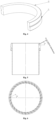
Fig. 5 is a front sectional structure view of a graphite gas ring in an embodiment of the present invention. -
Fig. 6 is a top view of a structure ofFig. 5 . - The embodiments of the present invention will be further illustrated below in conjunction with the drawings.
- A barrel-
shaped furnace body 1 is included. An up-down through cylindricalgraphite center pipe 4 is mounted in a middle of the furnace body. An insulating layer 2 and aheating coil 3 are provided on a periphery of the graphite center pipe for induction heating and insulation of the graphite center pipe. An upper end of the graphite center pipe is connected to an upper furnace mouth, and a lower end of the graphite center pipe is connected to a downwards-shrinkinglower furnace mouth 19. A protective gas ring structure is mounted on the upper furnace mouth. The protective gas ring structure includes ametal flange 5 mounted on the upper furnace mouth. An upper end of the metal flange is equipped with a metalgas intake ring 6. An upper end face of the metal flange is provided with an annular concave cavity, which fits with an annular boss on a lower end face of the metal gas intake ring. Coolingwater tanks gas intake cavity 20 is formed between the metal flange and an inner cavity below the metal gas intake ring. The metal gas intake ring communicates with a protective gas source through joint pipes and a control valve to make a protective gas enter the annular gas intake cavity. A graphite-glass composite gas ring is mounted on inner faces of the metal flange and the metal gas intake ring opposite to the annular gas intake cavity. The graphite-glass composite gas ring includes agraphite gas ring 8 in close fit with an inner hole of the metal flange. Circumferentially and uniformly spaced radial gas intake holes are formed in a periphery of an upper end of the graphite gas ring corresponding to the annular gas intake cavity. The radial gas intake holes are downwards tilting and radially deflecting gas intake holes, with a downwards tilting angle α of 25° and a radially deflecting angle β(towards the left) of 30°. The radial gas intake holes have a hole diameter of 2 mm. The number of the circumferentially and uniformly distributed gas intake holes is 32. A protective gas layer that rotates downwards and wraps anoptical fiber preform 18 is formed during gas intake. A lower end of the graphite gas ring downwards extends by a distance, with an axial direction being staggered with the graphite center pipe and a periphery fitting with a graphite center pipe inner hole. An insertion-type glassgas guide ring 9 is equipped in an inner hole of the graphite gas ring corresponding to the radial gas intake holes, and a periphery of an upper end of the insertion-type glass gas guide ring fits with an inner face of an upper end of the metal gas intake ring. A peripheral face of the insertion-type glass gas guide ring maintains a gap of 0.5-2 mm with the inner hole of the graphite gas ring and downwards extends by a distance to form an annular gas gap. A protective gas sprayed out from the circumferentially distributed gas intake holes in the upper end of the graphite gas ring enters the annular gas gap between the graphite gas ring and the insertion-type glass gas guide ring to form a protective gas ring layer that rotates downwards and wraps the optical fiber preform. The protective gas is inert gas. A furnace mouth sealing device is equipped on the protective gas ring structure. The furnace mouth sealing device is a glass ring quartz wool floating sealing device. The glass ring quartz wool floating sealing device includes an annularglass sealing holder 10 mounted at an upper end of the metal gas intake ring. An annular boss on a lower end face of the glass sealing holder fits with an annular concave cavity provided in an upper end face of the metal gas intake ring. An annular sealing groove provided in an inner hole of the glass sealing holder is filled with a sealingquartz wool 11 to constitute a secondary seal for the optical fiber preform. A radial floatingglass tightening ring 12 is mounted on the glass sealing holder. The radial floating glass tightening ring includes two glass arc blocks, which have a semicircle shape or a near-semicircle shape. Clampinggrooves 21 are formed in peripheral faces of the glass arc blocks. The two glass arc blocks are circumferentially spliced into a ring shape, clamp anannular spring 14 through the clamping grooves, and encircle a periphery of the quartzwool sealing layer 13 to constitute the radial floating glass tightening ring. A quartz wool sealing layer that wraps the optical fiber preform is provided in the radial floating glass tightening ring, the quartz wool sealing layer may be bundled through aquartz rope 15, and an upperglass pressure ring 16 is mounted at an upper end of the radial floating glass tightening ring, whereby constituting a primary seal for the optical fiber preform. When the outer diameter of the optical fiber preform fluctuates, the radial floating glass tightening ring will tighten or loosen the quartz wool sealing layer under the action of the annular spring to make the quartz wool sealing layer always tightly wrap the optical fiber preform, thereby ensuring axial feeding dynamic sealing during drawing of the optical fiber preform. - The above drawing furnace is used to make the optical fiber preform clamped on an ascending and descending feeding support device pass into the upper furnace mouth of the drawing furnace through the furnace mouth sealing device and the protective gas ring structure to enter a furnace cavity, the protective gas is turned on to enter the furnace cavity via the protective gas ring structure, the heating coil is turned on to heat the graphite center pipe, and the optical fiber preform is drawn into an optical fiber through high-temperature melting in a case that an interior of the drawing furnace is heated to 1950°C or so. During working, the protective gas has a gas flow of 30 L/min, and the protective gas is helium or argon. The optical fiber preform has an outer diameter of 220 mm. A fluctuation quantity (a difference between a maximum outer diameter and a minimum outer diameter) of an outer diameter of each optical fiber preform is 30 mm. The optical fiber preform has a feeding speed of 1.6 mm/min. The drawing speed is 3500 m/min.
Claims (15)
- An optical fiber drawing furnace, comprising a furnace body, an up-down through graphite center pipe being mounted in a middle of the furnace body, an insulating layer and a heating coil being provided on a periphery of the graphite center pipe, an upper end of the graphite center pipe being connected to an upper furnace mouth, a lower end of the graphite center pipe being connected to a downwards-shrinking lower furnace mouth, a protective gas ring structure being mounted on the upper furnace mouth, a furnace mouth sealing device being equipped on the protective gas ring structure, characterized in that the protective gas ring structure comprises a metal flange mounted on the upper furnace mouth, an upper end of the metal flange is equipped with a metal gas intake ring, an annular gas intake cavity is formed between the metal flange and the metal gas intake ring, and a graphite-glass composite gas ring is mounted on inner faces of the metal flange and the metal gas intake ring opposite to the annular gas intake cavity.
- The optical fiber drawing furnace according to claim 1, characterized in that the furnace mouth sealing device is a glass ring quartz wool floating sealing device.
- The optical fiber drawing furnace according to claim 1 or 2, characterized in that the graphite-glass composite gas ring comprises a graphite gas ring in close fit with an inner hole of the metal flange, circumferentially spaced radial gas intake holes are formed in a periphery of an upper end of the graphite gas ring corresponding to the annular gas intake cavity, an insertion-type glass gas guide ring is equipped in an inner hole of the graphite gas ring corresponding to the radial gas intake holes, and a periphery of an upper end of the insertion-type glass gas guide ring fits with an inner face of an upper end of the metal gas intake ring.
- The optical fiber drawing furnace according to claim 3, characterized in that a peripheral face of the insertion-type glass gas guide ring maintains a gap with the inner hole of the graphite gas ring and downwards extends by a distance to form an annular gas gap.
- The optical fiber drawing furnace according to claim 3, characterized in that circumferentially and uniformly spaced radial gas intake holes are formed in the periphery of the upper end of the graphite gas ring, the radial gas intake holes are downwards tilting and radially deflecting gas intake holes, and a protective gas layer that rotates downwards and wraps an optical fiber preform is formed during gas intake.
- The optical fiber drawing furnace according to claim 5, characterized in that the radial gas intake holes downwards tilt by an angle α of 10°-40° and radially deflect by an angle β of 15°-45°.
- The optical fiber drawing furnace according to claim 5 or 6, characterized in that the radial gas intake holes have a hole diameter of 1.5-3 mm, and a number of the circumferentially and uniformly distributed gas intake holes is 20-50.
- The optical fiber drawing furnace according to claim 3, characterized in that a lower end of the graphite gas ring downwards extends by a distance, with an axial direction being staggered with the graphite center pipe and a periphery fitting with an inner hole of the graphite center pipe.
- The optical fiber drawing furnace according to claim 2, characterized in that the glass ring quartz wool floating sealing device comprises a glass sealing holder mounted at an upper end of the metal gas intake ring, an annular sealing groove provided in an inner hole of the glass sealing holder is filled with a sealing quartz wool, a radial floating glass tightening ring is mounted on the glass sealing holder, a quartz wool sealing layer wrapping an optical fiber preform is provided in the radial floating glass tightening ring, and an upper glass pressure ring is mounted at an upper end of the radial floating glass tightening ring.
- The optical fiber drawing furnace according to claim 9, characterized in that the radial floating glass tightening ring comprises two to four glass arc blocks, clamping grooves are formed in peripheral faces of the glass arc blocks, and the glass arc blocks are circumferentially spliced into a ring shape, clamp an annular spring through the clamping grooves, and encircle a periphery of the quartz wool sealing layer to constitute the radial floating glass tightening ring.
- The optical fiber drawing furnace according to claim 1 or 2, characterized in that the metal gas intake ring communicates with a protective gas source through joint pipes and a control valve to make a protective gas enter the annular gas intake cavity.
- The optical fiber drawing furnace according to claim 1 or 2, characterized in that cooling water tanks are provided in the metal flange and the metal gas intake ring, respectively.
- An optical fiber drawing method, characterized by using the optical fiber drawing furnace according to any one of claims 1-12 to make an optical fiber preform clamped on an ascending and descending feeding support device pass into an upper furnace mouth of the optical fiber drawing furnace through the furnace mouth sealing device and the protective gas ring structure to enter a furnace cavity, turning on a protective gas to enter the furnace cavity via the protective gas ring structure, turning on the heating coil to heat the graphite center pipe, and drawing the optical fiber preform into an optical fiber through high-temperature melting in a case that an interior of the optical fiber drawing furnace is heated to 1700°C or above.
- The optical fiber drawing method according to claim 13, characterized in that the protective gas has a gas flow of 20-40 L/min, and the protective gas is helium or argon.
- The optical fiber drawing method according to claim 13, characterized in that the optical fiber preform has a feeding speed of 0.5-2 mm/min, and a maximum drawing speed is 3500 m/min.
Applications Claiming Priority (1)
| Application Number | Priority Date | Filing Date | Title |
|---|---|---|---|
| CN202311174864.0A CN117247229B (en) | 2023-09-11 | 2023-09-11 | Optical fiber drawing furnace and optical fiber drawing method |
Publications (4)
| Publication Number | Publication Date |
|---|---|
| EP4520735A2 true EP4520735A2 (en) | 2025-03-12 |
| EP4520735A3 EP4520735A3 (en) | 2025-03-19 |
| EP4520735B1 EP4520735B1 (en) | 2026-01-21 |
| EP4520735C0 EP4520735C0 (en) | 2026-01-21 |
Family
ID=89134205
Family Applications (1)
| Application Number | Title | Priority Date | Filing Date |
|---|---|---|---|
| EP24195833.9A Active EP4520735B1 (en) | 2023-09-11 | 2024-08-22 | Optical fiber drawing furnace and optical fiber drawing method |
Country Status (2)
| Country | Link |
|---|---|
| EP (1) | EP4520735B1 (en) |
| CN (1) | CN117247229B (en) |
Families Citing this family (2)
| Publication number | Priority date | Publication date | Assignee | Title |
|---|---|---|---|---|
| CN118084319B (en) * | 2024-03-01 | 2024-09-10 | 深圳市华盛智联科技有限公司 | Cooling equipment for optical fiber processing and manufacturing method of optical fiber |
| CN119161096B (en) * | 2024-11-22 | 2025-08-08 | 中国电子科技集团公司第四十六研究所 | Production system of high-strength fatigue-resistant optical fiber |
Family Cites Families (9)
| Publication number | Priority date | Publication date | Assignee | Title |
|---|---|---|---|---|
| CN1083033A (en) * | 1993-08-21 | 1994-03-02 | 冶金工业部钢铁研究总院 | Anti-oxidation method of graphite products |
| CN102838275B (en) * | 2012-08-28 | 2015-02-04 | 长飞光纤光缆股份有限公司 | Wiredrawing method and wiredrawing device for outer diameter fluctuation optical fiber perform |
| CN104445916B (en) * | 2014-12-26 | 2017-05-17 | 江苏法尔胜光子有限公司 | Top air sealing device for optical fiber drawing |
| CN104478210A (en) * | 2014-12-31 | 2015-04-01 | 江苏通鼎光棒有限公司 | Novel air sealing device and method for wire drawing furnace of uniform-diameter optical fiber preform rod |
| CN207891261U (en) * | 2018-01-26 | 2018-09-21 | 通鼎互联信息股份有限公司 | A kind of prefabricated stick drawn wire furnaceman dress and system for drawing |
| CN109592894A (en) * | 2018-12-25 | 2019-04-09 | 通鼎互联信息股份有限公司 | A kind of drawing optical fibers sealing device and encapsulating method |
| CN211111722U (en) * | 2019-12-27 | 2020-07-28 | 湖北凯乐量子通信光电科技有限公司 | Graphite assembly for heating optical fiber preform of optical fiber drawing furnace |
| CN214299889U (en) * | 2020-11-20 | 2021-09-28 | 长飞光纤光缆股份有限公司 | Optical fiber drawing furnace |
| CN112592048B (en) * | 2020-11-25 | 2022-08-16 | 通鼎互联信息股份有限公司 | Graphite piece structure for optical fiber drawing furnace |
-
2023
- 2023-09-11 CN CN202311174864.0A patent/CN117247229B/en active Active
-
2024
- 2024-08-22 EP EP24195833.9A patent/EP4520735B1/en active Active
Also Published As
| Publication number | Publication date |
|---|---|
| CN117247229A (en) | 2023-12-19 |
| CN117247229B (en) | 2025-09-02 |
| EP4520735B1 (en) | 2026-01-21 |
| EP4520735A3 (en) | 2025-03-19 |
| EP4520735C0 (en) | 2026-01-21 |
Similar Documents
| Publication | Publication Date | Title |
|---|---|---|
| EP4520735B1 (en) | Optical fiber drawing furnace and optical fiber drawing method | |
| US4174842A (en) | Non-contacting seal for treating chamber through which elongated material is moved | |
| CN102838275A (en) | Wiredrawing method and wiredrawing device for outer diameter fluctuation optical fiber perform | |
| KR20200109582A (en) | Fire Polishing Device for Inner Surface of Edge Ring | |
| CN207276495U (en) | A kind of air sealing device of wiredrawing furnace for reducing optical wand wire drawing | |
| US6845636B2 (en) | Apparatus for dehydrating and consolidating an optical fiber preform and method of the same | |
| CN114014534B (en) | Optical fiber drawing furnace gas sealing method and device adopting three-dimensional graphite felt sealing structure | |
| CN107555780B (en) | Sealing device under extension furnace | |
| CN214299889U (en) | Optical fiber drawing furnace | |
| WO2012163053A1 (en) | Induction furnace used for stretching large diameter preformed bars of optical fiber | |
| CN211946806U (en) | Optical fiber perform melts graphite stove that contracts | |
| CN207276494U (en) | One kind extension stove lower sealing device | |
| CN111186999A (en) | A vacuum drawing furnace for optical fiber manufacturing | |
| CN211896679U (en) | Vacuum wire drawing furnace for manufacturing optical fiber | |
| US4561874A (en) | Method for heat sealing a gun mount in a CRT neck | |
| KR102190744B1 (en) | Fire Polishing Method for Inner Surface of Edge Ring | |
| EP1165451B1 (en) | Method and apparatus for the thermal treatment of an object such as an optical fiber preform | |
| US11680007B2 (en) | Optical fiber glass preform and method for manufacturing optical fiber glass preform | |
| CN211424382U (en) | Low NOx wide flat flame burner | |
| JP3842003B2 (en) | Apparatus and method for manufacturing optical fiber preform base material | |
| CN107449314B (en) | A kind of metallic sheath float tube sealing structure | |
| CN111018337A (en) | HEC optical fiber collapsing furnace gas path system and gas sealing method | |
| KR900002596B1 (en) | Sealed system in cathode ray tube | |
| US2994916A (en) | Method and apparatus for melting glass and drawing filaments therefrom | |
| CN223936667U (en) | Exhaust system and single crystal furnace |
Legal Events
| Date | Code | Title | Description |
|---|---|---|---|
| PUAI | Public reference made under article 153(3) epc to a published international application that has entered the european phase |
Free format text: ORIGINAL CODE: 0009012 |
|
| STAA | Information on the status of an ep patent application or granted ep patent |
Free format text: STATUS: REQUEST FOR EXAMINATION WAS MADE |
|
| PUAL | Search report despatched |
Free format text: ORIGINAL CODE: 0009013 |
|
| 17P | Request for examination filed |
Effective date: 20240822 |
|
| AK | Designated contracting states |
Kind code of ref document: A2 Designated state(s): AL AT BE BG CH CY CZ DE DK EE ES FI FR GB GR HR HU IE IS IT LI LT LU LV MC ME MK MT NL NO PL PT RO RS SE SI SK SM TR |
|
| AK | Designated contracting states |
Kind code of ref document: A3 Designated state(s): AL AT BE BG CH CY CZ DE DK EE ES FI FR GB GR HR HU IE IS IT LI LT LU LV MC ME MK MT NL NO PL PT RO RS SE SI SK SM TR |
|
| RIC1 | Information provided on ipc code assigned before grant |
Ipc: C03B 37/029 20060101AFI20250210BHEP |
|
| GRAP | Despatch of communication of intention to grant a patent |
Free format text: ORIGINAL CODE: EPIDOSNIGR1 |
|
| STAA | Information on the status of an ep patent application or granted ep patent |
Free format text: STATUS: GRANT OF PATENT IS INTENDED |
|
| INTG | Intention to grant announced |
Effective date: 20251001 |
|
| GRAS | Grant fee paid |
Free format text: ORIGINAL CODE: EPIDOSNIGR3 |
|
| GRAA | (expected) grant |
Free format text: ORIGINAL CODE: 0009210 |
|
| STAA | Information on the status of an ep patent application or granted ep patent |
Free format text: STATUS: THE PATENT HAS BEEN GRANTED |
|
| AK | Designated contracting states |
Kind code of ref document: B1 Designated state(s): AL AT BE BG CH CY CZ DE DK EE ES FI FR GB GR HR HU IE IS IT LI LT LU LV MC ME MK MT NL NO PL PT RO RS SE SI SK SM TR |
|
| REG | Reference to a national code |
Ref country code: CH Ref legal event code: F10 Free format text: ST27 STATUS EVENT CODE: U-0-0-F10-F00 (AS PROVIDED BY THE NATIONAL OFFICE) Effective date: 20260121 |
|
| REG | Reference to a national code |
Ref country code: DE Ref legal event code: R096 Ref document number: 602024002170 Country of ref document: DE |
|
| REG | Reference to a national code |
Ref country code: IE Ref legal event code: FG4D |
|
| U01 | Request for unitary effect filed |
Effective date: 20260206 |
|
| U07 | Unitary effect registered |
Designated state(s): AT BE BG DE DK EE FI FR IT LT LU LV MT NL PT RO SE SI Effective date: 20260212 |