EP4520678A1 - Container having a locking closure - Google Patents
Container having a locking closure Download PDFInfo
- Publication number
- EP4520678A1 EP4520678A1 EP24198567.0A EP24198567A EP4520678A1 EP 4520678 A1 EP4520678 A1 EP 4520678A1 EP 24198567 A EP24198567 A EP 24198567A EP 4520678 A1 EP4520678 A1 EP 4520678A1
- Authority
- EP
- European Patent Office
- Prior art keywords
- degrees
- tab
- longitudinal axis
- package according
- peripheral wall
- Prior art date
- Legal status (The legal status is an assumption and is not a legal conclusion. Google has not performed a legal analysis and makes no representation as to the accuracy of the status listed.)
- Withdrawn
Links
Images


Classifications
-
- B—PERFORMING OPERATIONS; TRANSPORTING
- B65—CONVEYING; PACKING; STORING; HANDLING THIN OR FILAMENTARY MATERIAL
- B65D—CONTAINERS FOR STORAGE OR TRANSPORT OF ARTICLES OR MATERIALS, e.g. BAGS, BARRELS, BOTTLES, BOXES, CANS, CARTONS, CRATES, DRUMS, JARS, TANKS, HOPPERS, FORWARDING CONTAINERS; ACCESSORIES, CLOSURES, OR FITTINGS THEREFOR; PACKAGING ELEMENTS; PACKAGES
- B65D50/00—Closures with means for discouraging unauthorised opening or removal thereof, with or without indicating means, e.g. child-proof closures
- B65D50/02—Closures with means for discouraging unauthorised opening or removal thereof, with or without indicating means, e.g. child-proof closures openable or removable by the combination of plural actions
- B65D50/04—Closures with means for discouraging unauthorised opening or removal thereof, with or without indicating means, e.g. child-proof closures openable or removable by the combination of plural actions requiring the combination of simultaneous actions, e.g. depressing and turning, lifting and turning, maintaining a part and turning another one
- B65D50/045—Closures with means for discouraging unauthorised opening or removal thereof, with or without indicating means, e.g. child-proof closures openable or removable by the combination of plural actions requiring the combination of simultaneous actions, e.g. depressing and turning, lifting and turning, maintaining a part and turning another one where one action elastically deforms or deflects at least part of the closure, the container or an intermediate element, e.g. a ring
- B65D50/046—Closures with means for discouraging unauthorised opening or removal thereof, with or without indicating means, e.g. child-proof closures openable or removable by the combination of plural actions requiring the combination of simultaneous actions, e.g. depressing and turning, lifting and turning, maintaining a part and turning another one where one action elastically deforms or deflects at least part of the closure, the container or an intermediate element, e.g. a ring and such deformation causes the disengagement of locking means, e.g. the release of a pawl-like element from a tooth or abutment, to allow removal of the closure by simultaneous rotation
-
- B—PERFORMING OPERATIONS; TRANSPORTING
- B65—CONVEYING; PACKING; STORING; HANDLING THIN OR FILAMENTARY MATERIAL
- B65D—CONTAINERS FOR STORAGE OR TRANSPORT OF ARTICLES OR MATERIALS, e.g. BAGS, BARRELS, BOTTLES, BOXES, CANS, CARTONS, CRATES, DRUMS, JARS, TANKS, HOPPERS, FORWARDING CONTAINERS; ACCESSORIES, CLOSURES, OR FITTINGS THEREFOR; PACKAGING ELEMENTS; PACKAGES
- B65D41/00—Caps, e.g. crown caps or crown seals, i.e. members having parts arranged for engagement with the external periphery of a neck or wall defining a pouring opening or discharge aperture; Protective cap-like covers for closure members, e.g. decorative covers of metal foil or paper
- B65D41/02—Caps or cap-like covers without lines of weakness, tearing strips, tags, or like opening or removal devices
- B65D41/04—Threaded or like caps or cap-like covers secured by rotation
- B65D41/0471—Threaded or like caps or cap-like covers secured by rotation with means for positioning the cap on the container, or for limiting the movement of the cap, or for preventing accidental loosening of the cap
-
- B—PERFORMING OPERATIONS; TRANSPORTING
- B65—CONVEYING; PACKING; STORING; HANDLING THIN OR FILAMENTARY MATERIAL
- B65D—CONTAINERS FOR STORAGE OR TRANSPORT OF ARTICLES OR MATERIALS, e.g. BAGS, BARRELS, BOTTLES, BOXES, CANS, CARTONS, CRATES, DRUMS, JARS, TANKS, HOPPERS, FORWARDING CONTAINERS; ACCESSORIES, CLOSURES, OR FITTINGS THEREFOR; PACKAGING ELEMENTS; PACKAGES
- B65D41/00—Caps, e.g. crown caps or crown seals, i.e. members having parts arranged for engagement with the external periphery of a neck or wall defining a pouring opening or discharge aperture; Protective cap-like covers for closure members, e.g. decorative covers of metal foil or paper
- B65D41/02—Caps or cap-like covers without lines of weakness, tearing strips, tags, or like opening or removal devices
- B65D41/04—Threaded or like caps or cap-like covers secured by rotation
- B65D41/0485—Threaded or like caps or cap-like covers secured by rotation with means specially adapted for facilitating the operation of opening or closing
-
- B—PERFORMING OPERATIONS; TRANSPORTING
- B65—CONVEYING; PACKING; STORING; HANDLING THIN OR FILAMENTARY MATERIAL
- B65D—CONTAINERS FOR STORAGE OR TRANSPORT OF ARTICLES OR MATERIALS, e.g. BAGS, BARRELS, BOTTLES, BOXES, CANS, CARTONS, CRATES, DRUMS, JARS, TANKS, HOPPERS, FORWARDING CONTAINERS; ACCESSORIES, CLOSURES, OR FITTINGS THEREFOR; PACKAGING ELEMENTS; PACKAGES
- B65D47/00—Closures with filling and discharging, or with discharging, devices
- B65D47/04—Closures with discharging devices other than pumps
- B65D47/06—Closures with discharging devices other than pumps with pouring spouts or tubes; with discharge nozzles or passages
- B65D47/12—Closures with discharging devices other than pumps with pouring spouts or tubes; with discharge nozzles or passages having removable closures
- B65D47/122—Threaded caps
-
- B—PERFORMING OPERATIONS; TRANSPORTING
- B65—CONVEYING; PACKING; STORING; HANDLING THIN OR FILAMENTARY MATERIAL
- B65D—CONTAINERS FOR STORAGE OR TRANSPORT OF ARTICLES OR MATERIALS, e.g. BAGS, BARRELS, BOTTLES, BOXES, CANS, CARTONS, CRATES, DRUMS, JARS, TANKS, HOPPERS, FORWARDING CONTAINERS; ACCESSORIES, CLOSURES, OR FITTINGS THEREFOR; PACKAGING ELEMENTS; PACKAGES
- B65D47/00—Closures with filling and discharging, or with discharging, devices
- B65D47/04—Closures with discharging devices other than pumps
- B65D47/06—Closures with discharging devices other than pumps with pouring spouts or tubes; with discharge nozzles or passages
- B65D47/12—Closures with discharging devices other than pumps with pouring spouts or tubes; with discharge nozzles or passages having removable closures
- B65D47/122—Threaded caps
- B65D47/123—Threaded caps with internal parts
-
- B—PERFORMING OPERATIONS; TRANSPORTING
- B65—CONVEYING; PACKING; STORING; HANDLING THIN OR FILAMENTARY MATERIAL
- B65D—CONTAINERS FOR STORAGE OR TRANSPORT OF ARTICLES OR MATERIALS, e.g. BAGS, BARRELS, BOTTLES, BOXES, CANS, CARTONS, CRATES, DRUMS, JARS, TANKS, HOPPERS, FORWARDING CONTAINERS; ACCESSORIES, CLOSURES, OR FITTINGS THEREFOR; PACKAGING ELEMENTS; PACKAGES
- B65D55/00—Accessories for container closures not otherwise provided for
- B65D55/02—Locking devices; Means for discouraging or indicating unauthorised opening or removal of closure
-
- B—PERFORMING OPERATIONS; TRANSPORTING
- B65—CONVEYING; PACKING; STORING; HANDLING THIN OR FILAMENTARY MATERIAL
- B65D—CONTAINERS FOR STORAGE OR TRANSPORT OF ARTICLES OR MATERIALS, e.g. BAGS, BARRELS, BOTTLES, BOXES, CANS, CARTONS, CRATES, DRUMS, JARS, TANKS, HOPPERS, FORWARDING CONTAINERS; ACCESSORIES, CLOSURES, OR FITTINGS THEREFOR; PACKAGING ELEMENTS; PACKAGES
- B65D2255/00—Locking devices
Definitions
- Locking closure for a container Locking closure for a container.
- Packages of liquid are commonly moved in commerce.
- Packages for liquids often comprise a container and a closure engaged with the container.
- Threaded closures are commonly used to close containers.
- a threaded closure Prior to shipment, a threaded closure is engaged with a container by a machine that screws the closure onto the open end of the container.
- packages for liquids are often subjected to vibrations and impacts that can cause the threads of the closure to back off from the position in which the closure is sealingly engaged with the container.
- a problem associated with the threads of the closure backing off is that the user may unintentionally open the package since little force is required to unscrew the closure once the closure is not sealingly engaged with the container.
- a package (10) comprising: a closure (20) engaged with a container (30), wherein said closure comprises: a threaded collar (40) and a peripheral wall (50) extending from said threaded collar, wherein said peripheral wall extends around a longitudinal axis (L) and has an engagement rotation direction (E) in which said threaded collar engages with said container and a disengagement rotation direction (D) in which said thread collar disengages with said container; a tab (60) outboard of and spaced apart from said peripheral wall and connected to said peripheral wall by a deformable first arm (70) extending from a first arm attachment location (80) on said peripheral wall to said tab and deformable second arm (90) extending from a second arm attachment location (100) on said peripheral wall to said tab, wherein said second arm attachment location is radially offset from said first arm attachment location by from about 2 degrees to about 30 degrees in the engagement rotation direction, wherein said first arm attachment location is radially offset from said tab by from about 0.5 degrees to about 20 degrees in the engagement
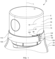
- FIG. 1 A perspective view of a package 10 is shown in Figure 1 .
- the package 10 comprises a closure 20 engaged with a container 30.
- the closure 20 comprises a threaded collar (40) and a peripheral wall 50 extending from the threaded collar, wherein the peripheral wall extends around a longitudinal axis L and has an engagement rotation direction E in which the threaded collar engages with the container and a disengagement rotation direction D in which the thread collar disengages with the container.
- the closure 20 comprises a tab 60 outboard of and spaced apart from the peripheral wall and connected to the peripheral wall by a deformable first arm 70 extending from a first arm attachment location 80 on the peripheral wall to the tab.
- the closure 20 further comprises a deformable second arm 90 extending from a second arm attachment location 100 on the peripheral wall 50 to the tab 60.
- the second arm attachment location 100 can be radially offset from the first arm attachment location 80 by from about 2 degrees to about 30 degrees in the engagement rotation direction E.
- the first arm attachment location 80 can be radially offset from the tab 60 by from about 0.5 degrees to about 20 degrees in the engagement rotation direction E.
- the tab has a tab width W orthogonal to the longitudinal axis. The tab width is a scalar quantity.
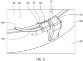
- the container 30 comprises an open end 110 about the longitudinal axis L and an abutment 120 projecting above the open end and outboard of the open end and spaced apart from the peripheral wall by a clearance distance C.
- the clearance distance C is a scalar quantity.
- the clearance distance C can be greater than or equal to the tab width W.
- the tab 60 can be abutted against the abutment 120.
- the user presses the tab 60 towards the longitudinal axis to dislodge the tab 60 from the abutment 120. Then the user rotates the closure 20 in the disengagement rotation direction D to move the tab past the abutment 120.
- the closure 20 comprises two the tabs 60 positioned radially opposite one another about the longitudinal axis L and the container comprises two the abutments 120 positioned radially opposite one another about the longitudinal axis L.
- the process of opening the package 10 process comprises the steps of pressing the tabs 60 towards the longitudinal axis L to dislodge the tabs 60 from the abutments 120.
- the tab 60 or tabs 60 can have a first position abutting the abutment 120 or abutments 120 and a second position in which the tab 60 or tabs 60 are inboard of the abutment 120 or abutments 120 and rotatable in said disengagement rotation direction D past the abutment 120 or abutments 120.
- the tab 60 or tabs 60 in combination with the abutment 120 or abutments 120 can help to resist backing off of the closure.
- the deformable first arm 70 and deformable second arm 90 can provide for flexible structures that can be deformed, optionally elastically deformed, by the user pushing on the tab 60 or tabs 60. The user can push the tab 60 or tabs 60 in far enough so that the tab 60 or tabs 60 can rotationally move past the abutment 120 or abutments 120 so that the closure 20 can be removed from the container 30.
- the deformable first arm 70 and deformable second arm 90 can extend from away from the peripheral wall 50 at the first arm attachment location 80 and second arm attachment location 100 in a direction, respectively, in a direction about the longitudinal axis L in the disengagement rotation direction D.
- the second arm attachment location can be radially offset from said first arm attachment location by from about 2 degrees to about 20 degrees, optionally from about 2 degrees to about 15 degrees, optionally from about 2 degrees to about 10 degrees, in the engagement rotation direction.
- the first arm attachment location can be radially offset from said tab by from about 0.5 degrees to about 15 degrees, optionally from about 0.5 degrees to about 10 degrees, from about 0.5 degrees to about 5 degrees, from about 2 degrees to about 20 degrees, from about 2 degrees to about 15 degrees, from about 2 degrees to about 10 degrees, in the engagement rotation direction.
- the open end 110 can comprise a spout fitment 130, optionally a drain back spout fitment 150, engaged with the container body 140.
- the spout fitment can comprise a spout 180 that projects into the closure 20. A portion of the spout 180 can be positioned between the peripheral wall 50 and the longitudinal axis L.
- the threaded collar 40 can be continuous about the longitudinal axis L.
- the threaded collar 40 can have one or more slots positioned around the longitudinal axis L.
- the threaded collar 40, peripheral wall 50, tab 60, deformable first arm 70, and said deformable second arm 90 can be unitary with one another and comprised of plastic, optionally a thermoset plastic.
- Each tab 60 can have an engaged portion abutting the abutment 120.
- the engaged portion can have a height H.
- the threaded collar 40 can comprise threads having a pitch P.
- the pitch P can be at least twice the height H.
- a 180 degree rotation in the disengagement direction D can move the closure 20 along the longitudinal axis L such that the tab 60 does not collide with an abutment 120 on the other side of the container 30.
Landscapes
- Engineering & Computer Science (AREA)
- Mechanical Engineering (AREA)
- Closures For Containers (AREA)
- Cartons (AREA)
Abstract
A package including a closure engaged with a container. The closure has one or more tabs that abut one or more abutments. The tabs can be displaced towards the longitudinal axis and the closure can be rotated in the disengagement direction to dislodge the closure from the container.
Description
- Locking closure for a container.
- Packages of liquid are commonly moved in commerce. Packages for liquids often comprise a container and a closure engaged with the container. Threaded closures are commonly used to close containers. Prior to shipment, a threaded closure is engaged with a container by a machine that screws the closure onto the open end of the container. During transport from the filling location to the user's home, packages for liquids are often subjected to vibrations and impacts that can cause the threads of the closure to back off from the position in which the closure is sealingly engaged with the container. A problem associated with the threads of the closure backing off is that the user may unintentionally open the package since little force is required to unscrew the closure once the closure is not sealingly engaged with the container. Another problem associated with the threads of the closure backing off is that the package may leak, especially if the package is tipped over or inverted. With these limitations in mind, there is a continuing unaddressed need for a package having a closure system in which the closure is restrained from unintentional opening or backing off during transport.
- A package (10) comprising: a closure (20) engaged with a container (30), wherein said closure comprises: a threaded collar (40) and a peripheral wall (50) extending from said threaded collar, wherein said peripheral wall extends around a longitudinal axis (L) and has an engagement rotation direction (E) in which said threaded collar engages with said container and a disengagement rotation direction (D) in which said thread collar disengages with said container; a tab (60) outboard of and spaced apart from said peripheral wall and connected to said peripheral wall by a deformable first arm (70) extending from a first arm attachment location (80) on said peripheral wall to said tab and deformable second arm (90) extending from a second arm attachment location (100) on said peripheral wall to said tab, wherein said second arm attachment location is radially offset from said first arm attachment location by from about 2 degrees to about 30 degrees in the engagement rotation direction, wherein said first arm attachment location is radially offset from said tab by from about 0.5 degrees to about 20 degrees in the engagement rotation direction, wherein said tab has a tab width (W) orthogonal to said longitudinal axis; wherein said container comprises; an open end (110) about said longitudinal axis; and an abutment (120) projecting above said open end and outboard of said open end and spaced apart from said peripheral wall by a clearance distance (C), wherein said clearance distance is greater than or equal to said tab width, and wherein said tab is abutted against said abutment.
-
-
Figure 1 is a perspective view of a package including a closure engaged with a spout fitment that is part of the open end of a container. -
Figure 2 is partial view of a closure engaged with a spout fitment that is part of the open end of a container. -
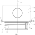
Figure 3 is a side view of a closure. -
Figure 4 is a top view of a closure. -
Figure 5 is a side view of a spout fitment. -
Figure 6 is a top view of a spout fitment. - A perspective view of a
package 10 is shown inFigure 1 . Thepackage 10 comprises aclosure 20 engaged with acontainer 30. Theclosure 20 comprises a threaded collar (40) and aperipheral wall 50 extending from the threaded collar, wherein the peripheral wall extends around a longitudinal axis L and has an engagement rotation direction E in which the threaded collar engages with the container and a disengagement rotation direction D in which the thread collar disengages with the container. - The
closure 20 comprises atab 60 outboard of and spaced apart from the peripheral wall and connected to the peripheral wall by a deformablefirst arm 70 extending from a firstarm attachment location 80 on the peripheral wall to the tab. Theclosure 20 further comprises a deformablesecond arm 90 extending from a secondarm attachment location 100 on theperipheral wall 50 to thetab 60. The secondarm attachment location 100 can be radially offset from the firstarm attachment location 80 by from about 2 degrees to about 30 degrees in the engagement rotation direction E. The firstarm attachment location 80 can be radially offset from thetab 60 by from about 0.5 degrees to about 20 degrees in the engagement rotation direction E. The tab has a tab width W orthogonal to the longitudinal axis. The tab width is a scalar quantity. - The
container 30 comprises anopen end 110 about the longitudinal axis L and anabutment 120 projecting above the open end and outboard of the open end and spaced apart from the peripheral wall by a clearance distance C. The clearance distance C is a scalar quantity. The clearance distance C can be greater than or equal to the tab width W. Thetab 60 can be abutted against theabutment 120. - To unscrew the
closure 20 from thecontainer 30, the user presses thetab 60 towards the longitudinal axis to dislodge thetab 60 from theabutment 120. Then the user rotates theclosure 20 in the disengagement rotation direction D to move the tab past theabutment 120. Optionally, theclosure 20 comprises two thetabs 60 positioned radially opposite one another about the longitudinal axis L and the container comprises two theabutments 120 positioned radially opposite one another about the longitudinal axis L. The process of opening thepackage 10 process comprises the steps of pressing thetabs 60 towards the longitudinal axis L to dislodge thetabs 60 from theabutments 120. Then the user can rotate theclosure 20 in the disengagement rotation direction D to move thetabs 60 past theabutments 120. Thetab 60 ortabs 60 can have a first position abutting theabutment 120 orabutments 120 and a second position in which thetab 60 ortabs 60 are inboard of theabutment 120 orabutments 120 and rotatable in said disengagement rotation direction D past theabutment 120 orabutments 120. - The
tab 60 ortabs 60 in combination with theabutment 120 orabutments 120 can help to resist backing off of the closure. The deformablefirst arm 70 and deformablesecond arm 90 can provide for flexible structures that can be deformed, optionally elastically deformed, by the user pushing on thetab 60 ortabs 60. The user can push thetab 60 ortabs 60 in far enough so that thetab 60 ortabs 60 can rotationally move past theabutment 120 orabutments 120 so that theclosure 20 can be removed from thecontainer 30. - The deformable
first arm 70 and deformablesecond arm 90 can extend from away from theperipheral wall 50 at the firstarm attachment location 80 and secondarm attachment location 100 in a direction, respectively, in a direction about the longitudinal axis L in the disengagement rotation direction D. - The second arm attachment location can be radially offset from said first arm attachment location by from about 2 degrees to about 20 degrees, optionally from about 2 degrees to about 15 degrees, optionally from about 2 degrees to about 10 degrees, in the engagement rotation direction. The first arm attachment location can be radially offset from said tab by from about 0.5 degrees to about 15 degrees, optionally from about 0.5 degrees to about 10 degrees, from about 0.5 degrees to about 5 degrees, from about 2 degrees to about 20 degrees, from about 2 degrees to about 15 degrees, from about 2 degrees to about 10 degrees, in the engagement rotation direction.
- The
open end 110 can comprise aspout fitment 130, optionally a drainback spout fitment 150, engaged with thecontainer body 140. The spout fitment can comprise aspout 180 that projects into theclosure 20. A portion of thespout 180 can be positioned between theperipheral wall 50 and the longitudinal axis L. - The threaded
collar 40 can be continuous about the longitudinal axis L. Optionally, the threadedcollar 40 can have one or more slots positioned around the longitudinal axis L. - The threaded
collar 40,peripheral wall 50,tab 60, deformablefirst arm 70, and said deformablesecond arm 90 can be unitary with one another and comprised of plastic, optionally a thermoset plastic. - Each
tab 60 can have an engaged portion abutting theabutment 120. The engaged portion can have a height H. The threadedcollar 40 can comprise threads having a pitch P. The pitch P can be at least twice the height H. In such an arrangement, a 180 degree rotation in the disengagement direction D can move theclosure 20 along the longitudinal axis L such that thetab 60 does not collide with anabutment 120 on the other side of thecontainer 30. - The dimensions and values disclosed herein are not to be understood as being strictly limited to the exact numerical values recited. Instead, unless otherwise specified, each such dimension is intended to mean both the recited value and a functionally equivalent range surrounding that value. For example, a dimension disclosed as "40 mm" is intended to mean "about 40 mm."
- Every document cited herein, including any cross referenced or related patent or application and any patent application or patent to which this application claims priority or benefit thereof, is hereby incorporated herein by reference in its entirety unless expressly excluded or otherwise limited. The citation of any document is not an admission that it is prior art with respect to any invention disclosed or claimed herein or that it alone, or in any combination with any other reference or references, teaches, suggests or discloses any such invention. Further, to the extent that any meaning or definition of a term in this document conflicts with any meaning or definition of the same term in a document incorporated by reference, the meaning or definition assigned to that term in this document shall govern.
- While particular embodiments of the present invention have been illustrated and described, it would be obvious to those skilled in the art that various other changes and modifications can be made without departing from the spirit and scope of the invention. It is therefore intended to cover in the appended claims all such changes and modifications that are within the scope of this invention.
Claims (15)
- A package (10) comprising:
a closure (20) engaged with a container (30), wherein said closure comprises:a threaded collar (40) and a peripheral wall (50) extending from said threaded collar, wherein said peripheral wall extends around a longitudinal axis (L) and has an engagement rotation direction (E) in which said threaded collar engages with said container and a disengagement rotation direction (D) in which said thread collar disengages with said container;a tab (60) outboard of and spaced apart from said peripheral wall and connected to said peripheral wall by a deformable first arm (70) extending from a first arm attachment location (80) on said peripheral wall to said tab and deformable second arm (90) extending from a second arm attachment location (100) on said peripheral wall to said tab, wherein said second arm attachment location is radially offset from said first arm attachment location by from about 2 degrees to about 30 degrees in the engagement rotation direction, wherein said first arm attachment location is radially offset from said tab by from about 0.5 degrees to about 20 degrees in the engagement rotation direction, wherein said tab has a tab width (W) orthogonal to said longitudinal axis;wherein said container comprises;an open end (110) about said longitudinal axis; andan abutment (120) projecting above said open end and outboard of said open end and spaced apart from said peripheral wall by a clearance distance (C), wherein said clearance distance is greater than or equal to said tab width, and wherein said tab is abutted against said abutment. - The package according to Claim 1, wherein said second arm attachment location is radially offset from said first arm attachment location by from about 2 degrees to about 20 degrees, optionally from about 2 degrees to about 15 degrees, optionally from about 2 degrees to about 10 degrees, in the engagement rotation direction.
- The package according to Claim 1 or Claim 2, wherein said first arm attachment location is radially offset from said tab by from about 0.5 degrees to about 15 degrees, optionally from about 0.5 degrees to about 10 degrees, from about 0.5 degrees to about 5 degrees, from about 2 degrees to about 20 degrees, from about 2 degrees to about 15 degrees, from about 2 degrees to about 10 degrees, in the engagement rotation direction.
- The package according to any one of Claims 1 to 3, wherein said open end comprises a spout fitment (130) engaged with a container body (140).
- The package according to Claim 4, wherein said spout fitment is a drain back spout fitment (150).
- The package according to Claim 4 or 5, wherein said threaded collar comprises threads (160) oriented away from said longitudinal axis and said spout fitment comprises complementary threads (170) oriented towards said longitudinal axis.
- The package according to any one of Claims 4 to 6, wherein said spout fitment comprises a spout (180) projecting into said closure and a portion of said spout is positioned between said peripheral wall and said longitudinal axis.
- The package according to any one of Claims 1 to 7, wherein said threaded collar is continuous about said longitudinal axis.
- The package according to any one of Claims 1 to 8, wherein said threaded collar is discontinuous about said longitudinal axis.
- The package according to any one of Claims 1 to 9, wherein said tab has a first position abutting said abutment and a second position in which said tab is inboard of said abutment and rotatable in said disengagement rotation direction past said abutment.
- The package according to any one of Claims 1 to 10, wherein said threaded collar, said peripheral wall, tab, deformable first arm and said deformable second arm are unitary with one another.
- The package according to any one of Claims 1 to 11, wherein said threaded collar, said peripheral wall, said tab, said deformable first arm and said deformable second arm are unitary with one another and comprised of plastic, optionally a thermoset plastic.
- The package according to any one of Claims 1 to 12, wherein said closure comprises two said tabs positioned radially opposite one another about said longitudinal axis and said container comprises two said abutments positioned radially opposite one another about said longitudinal axis.
- The package according to any one of Claims 1 to 13, wherein said tab has an engaged portion abutting said abutment, wherein said engaged portion has a height (H), wherein said threaded collar comprises threads having a pitch (P), wherein said pitch is at least twice said height.
- A process for opening the package of any one of Claims 1 to 14 comprising the steps of: pressing said tab towards said longitudinal axis to dislodge said tab from said abutment; rotating said closure in said disengagement rotation direction to move said tab past said abutment.
Applications Claiming Priority (1)
| Application Number | Priority Date | Filing Date | Title |
|---|---|---|---|
| US202363580602P | 2023-09-05 | 2023-09-05 |
Publications (1)
| Publication Number | Publication Date |
|---|---|
| EP4520678A1 true EP4520678A1 (en) | 2025-03-12 |
Family
ID=92708557
Family Applications (1)
| Application Number | Title | Priority Date | Filing Date |
|---|---|---|---|
| EP24198567.0A Withdrawn EP4520678A1 (en) | 2023-09-05 | 2024-09-05 | Container having a locking closure |
Country Status (4)
| Country | Link |
|---|---|
| US (1) | US20250074662A1 (en) |
| EP (1) | EP4520678A1 (en) |
| MX (1) | MX2026002533A (en) |
| WO (1) | WO2025054157A1 (en) |
Citations (8)
| Publication number | Priority date | Publication date | Assignee | Title |
|---|---|---|---|---|
| US3989152A (en) * | 1976-02-09 | 1976-11-02 | Sunbeam Plastics Corporation | Child-resistant locking means for a twist-action container cap |
| US5165559A (en) * | 1990-02-01 | 1992-11-24 | Owens-Illinois Closure Inc. | Child resistant closure and package |
| US5379910A (en) * | 1992-12-16 | 1995-01-10 | Sunbeam Plastics Corporation | Apparatus for sealing a container and closure |
| US5992657A (en) * | 1998-05-28 | 1999-11-30 | Rexam Plastics Inc. | Safety closure having tamper-indicating means |
| US6065648A (en) * | 1999-06-29 | 2000-05-23 | Poly-Seal Corporation | Child resistant dispenser |
| US6279766B1 (en) * | 1999-08-10 | 2001-08-28 | Rexam Medical Packaging Inc. | Safety closure with tamper-resistant locking tab and method and apparatus for making same |
| US20170029179A1 (en) * | 2015-07-29 | 2017-02-02 | Berry Plastics Corporation | Child-resistant package |
| US20180319555A1 (en) * | 2017-05-04 | 2018-11-08 | Berry Global, Inc. | Closure |
Family Cites Families (48)
| Publication number | Priority date | Publication date | Assignee | Title |
|---|---|---|---|---|
| US3160301A (en) * | 1963-10-11 | 1964-12-08 | K C K Holding Company | Container and safety closure therefor |
| US3233769A (en) * | 1964-03-02 | 1966-02-08 | Peter M Jessop | Screw-capped containers and safety devices therefor |
| FR1491263A (en) * | 1966-04-18 | 1967-08-11 | Safety cap for pharmaceutical bottles and containers | |
| US3445022A (en) * | 1967-12-21 | 1969-05-20 | Frank A Cilluffo | Childproof safety container and closure |
| US3623622A (en) * | 1970-07-13 | 1971-11-30 | Westhem Corp Ltd | Safety locking closure |
| US3984021A (en) * | 1972-09-11 | 1976-10-05 | Uhlig Gerhardt E | Safety closure container |
| US3884379A (en) * | 1972-12-11 | 1975-05-20 | Eyelet Specialty Co | Bottle safety closure |
| US3902621A (en) * | 1974-08-05 | 1975-09-02 | Walter E Hidding | Tamperproof closure with grippable handle |
| US4154353A (en) * | 1978-08-04 | 1979-05-15 | Hoo William K C | Safety container |
| US4331247A (en) * | 1980-09-15 | 1982-05-25 | Owens-Illinois, Inc. | One piece child-resistant closure |
| US4383618A (en) * | 1982-02-12 | 1983-05-17 | Dougherty Brothers Company | Childproof container |
| US4540098A (en) * | 1984-09-28 | 1985-09-10 | Sunbeam Plastics Corporation | Tamper indicating child resistant closure |
| US4567991A (en) * | 1984-10-12 | 1986-02-04 | Sunbeam Plastics Corporation | Tamper indicating child resistant closure |
| US4572385A (en) * | 1985-04-11 | 1986-02-25 | Sunbeam Plastics Corporation | Tamper indicating child resistant threaded closure |
| US4613051A (en) * | 1985-08-12 | 1986-09-23 | Swartzbaugh Peter T | Child-resistant package |
| US5058754A (en) * | 1990-12-06 | 1991-10-22 | Hickerson Frederick R | Child resistant container and safety closure |
| CZ190894A3 (en) * | 1992-02-07 | 1995-11-15 | Procter & Gamble | Atomizer with a plurality of holes for atomizing liquid in various patterns |
| US5460281A (en) * | 1994-09-15 | 1995-10-24 | West Penn Plastics | Safety lock screw cap and container |
| US6036036A (en) * | 1995-06-28 | 2000-03-14 | The Procter & Gamble Company | Adult friendly child-resistant package |
| US5788098A (en) * | 1997-01-23 | 1998-08-04 | Mader; Stanley C. | Child resistant container closure system with locking ring, hook element, and cap |
| US5941402A (en) * | 1997-06-24 | 1999-08-24 | Kerr | Child-resistant closure and container apparatus |
| GB0121867D0 (en) * | 2001-09-11 | 2001-10-31 | Dubois Ltd | Container |
| FR2834276B1 (en) * | 2002-01-03 | 2004-06-11 | Tetra Laval Holdings & Finance | SEALING DEVICE AND CONTAINER PROVIDED WITH SUCH A DEVICE |
| US6843389B2 (en) * | 2002-07-19 | 2005-01-18 | Rieke Corporation | Sealing mechanisms for use in liquid-storage containers |
| US7922041B2 (en) * | 2005-12-29 | 2011-04-12 | The Procter & Gamble Company | Spray dispensers |
| GB0720163D0 (en) * | 2007-10-16 | 2007-11-28 | Jaycare Ltd | Closure |
| US7942280B2 (en) * | 2008-06-05 | 2011-05-17 | Apothecary Products, Inc. | Push tab vial assembly and methods |
| US8011525B2 (en) * | 2008-11-24 | 2011-09-06 | Rexam Healthcare Packaging Inc. | Child-resistant container having a deflectable release |
| US8281948B2 (en) * | 2009-05-12 | 2012-10-09 | Enpac, L.L.C. | Overpack salvage drum |
| US8162165B2 (en) * | 2009-10-13 | 2012-04-24 | Bway Corporation | Pail and closure |
| US9527619B2 (en) * | 2009-10-21 | 2016-12-27 | Innovative Bottles, Inc. | Biodegradable pharmacy container and safety cap |
| CA2746283A1 (en) * | 2010-09-10 | 2012-03-10 | Sulzer Mixpac Ag | Childproof closure for a dispensing apparatus |
| KR101221795B1 (en) * | 2010-10-29 | 2013-01-14 | (주)연우 | A Safety Cap |
| US8689995B2 (en) * | 2010-12-07 | 2014-04-08 | Letica Corporation | Child resistant, tamper evident container |
| TWM433379U (en) * | 2012-03-02 | 2012-07-11 | Accton Tech Corp | Anti-theft box for electronic device |
| GB2519205B (en) * | 2013-08-16 | 2017-02-08 | Mwv Slatersville Llc | Two-piece child-resistant dispensing closure |
| US9422091B2 (en) * | 2013-12-19 | 2016-08-23 | Berry Plastics Corporation | Closure for container |
| FR3035647B1 (en) * | 2015-04-28 | 2019-08-02 | Nemera La Verpilliere | DEVICE FOR CLOSING A CONTAINER BY SCREWING, SECURED BY A RECOVERABLE ERGOT. |
| US20170001764A1 (en) * | 2015-07-02 | 2017-01-05 | Richards Packaging Inc. - Emballages Richards Inc. | Convertible childproof to non-childproof bottle and method of opening same |
| US20210276769A1 (en) * | 2016-10-31 | 2021-09-09 | Plastek Industries, Inc. | Child-Resistant Closure |
| AT520977B1 (en) * | 2018-01-11 | 2020-02-15 | Joma Kunststofftechnik Gmbh | container |
| US11491082B2 (en) * | 2018-08-21 | 2022-11-08 | Bioflex Solutions, Llc | Cover for drug product bottles |
| US10865022B2 (en) * | 2019-02-19 | 2020-12-15 | Jui-Te Wang | Seal bottle assembly |
| WO2020219509A1 (en) * | 2019-04-23 | 2020-10-29 | Berry Global, Inc. | Selectively openable closure for a container |
| US11414244B2 (en) * | 2020-10-29 | 2022-08-16 | Cheer Pack North America | System and method for connecting members |
| US12122570B2 (en) * | 2021-07-21 | 2024-10-22 | Berry Global, Inc. | Package with child-safety closure |
| US12325567B2 (en) * | 2021-11-11 | 2025-06-10 | Battelle Savannah River Alliance, Llc | Tamper-indicating device having robotic application features |
| US12304719B1 (en) * | 2022-07-21 | 2025-05-20 | Jose Gonzalez | Pivoting cap with locking mechanism for medication dispenser |
-
2024
- 2024-09-04 US US18/824,251 patent/US20250074662A1/en active Pending
- 2024-09-04 WO PCT/US2024/045110 patent/WO2025054157A1/en active Pending
- 2024-09-05 EP EP24198567.0A patent/EP4520678A1/en not_active Withdrawn
-
2026
- 2026-03-03 MX MX2026002533A patent/MX2026002533A/en unknown
Patent Citations (8)
| Publication number | Priority date | Publication date | Assignee | Title |
|---|---|---|---|---|
| US3989152A (en) * | 1976-02-09 | 1976-11-02 | Sunbeam Plastics Corporation | Child-resistant locking means for a twist-action container cap |
| US5165559A (en) * | 1990-02-01 | 1992-11-24 | Owens-Illinois Closure Inc. | Child resistant closure and package |
| US5379910A (en) * | 1992-12-16 | 1995-01-10 | Sunbeam Plastics Corporation | Apparatus for sealing a container and closure |
| US5992657A (en) * | 1998-05-28 | 1999-11-30 | Rexam Plastics Inc. | Safety closure having tamper-indicating means |
| US6065648A (en) * | 1999-06-29 | 2000-05-23 | Poly-Seal Corporation | Child resistant dispenser |
| US6279766B1 (en) * | 1999-08-10 | 2001-08-28 | Rexam Medical Packaging Inc. | Safety closure with tamper-resistant locking tab and method and apparatus for making same |
| US20170029179A1 (en) * | 2015-07-29 | 2017-02-02 | Berry Plastics Corporation | Child-resistant package |
| US20180319555A1 (en) * | 2017-05-04 | 2018-11-08 | Berry Global, Inc. | Closure |
Also Published As
| Publication number | Publication date |
|---|---|
| WO2025054157A1 (en) | 2025-03-13 |
| MX2026002533A (en) | 2026-04-01 |
| US20250074662A1 (en) | 2025-03-06 |
Similar Documents
| Publication | Publication Date | Title |
|---|---|---|
| US4084717A (en) | Container and closure | |
| US5676270A (en) | Threaded container torque retention system for use with a threaded closure | |
| EP0592580B1 (en) | Container-closure assembly | |
| US6543650B1 (en) | Double shell dispenser | |
| EP1092643B1 (en) | Child-resistant squeeze-and-turn closure and method of manufacturing | |
| US4540098A (en) | Tamper indicating child resistant closure | |
| US5009323A (en) | Tamper indicating closure having a rotary seal | |
| US5370251A (en) | Child-resistant closure | |
| US5641099A (en) | Nestable pouring spout assembly | |
| US20030160020A1 (en) | Closure and container and combination thereof with anti-backoff member | |
| EP0440480B1 (en) | Child resistant package | |
| CA2053444A1 (en) | Child resistant spout package | |
| US6044994A (en) | Sealing arrangement for closure caps having liners | |
| CN117242015A (en) | Closure with retaining ring and tamper-evident tape | |
| JPH11501889A (en) | Containers with lids that cannot be easily removed | |
| US5988412A (en) | Safety closure having an internal locking lug | |
| GB2257693A (en) | Container closure | |
| US5727703A (en) | Child resistant package utilizing one piece closure | |
| GB2105693A (en) | Closures and containers | |
| JP5727158B2 (en) | Lockable hinge assembly | |
| JPH0848357A (en) | Screw cap with welding ring | |
| US5566864A (en) | Childproof closure for a container comprising a lower portion with extensible spout and a screw cap | |
| US5379910A (en) | Apparatus for sealing a container and closure | |
| US20250074662A1 (en) | Container having a locking closure | |
| US6354450B1 (en) | Locking helical closure system |
Legal Events
| Date | Code | Title | Description |
|---|---|---|---|
| PUAI | Public reference made under article 153(3) epc to a published international application that has entered the european phase |
Free format text: ORIGINAL CODE: 0009012 |
|
| STAA | Information on the status of an ep patent application or granted ep patent |
Free format text: STATUS: THE APPLICATION HAS BEEN PUBLISHED |
|
| AK | Designated contracting states |
Kind code of ref document: A1 Designated state(s): AL AT BE BG CH CY CZ DE DK EE ES FI FR GB GR HR HU IE IS IT LI LT LU LV MC ME MK MT NL NO PL PT RO RS SE SI SK SM TR |
|
| STAA | Information on the status of an ep patent application or granted ep patent |
Free format text: STATUS: THE APPLICATION IS DEEMED TO BE WITHDRAWN |
|
| 18D | Application deemed to be withdrawn |
Effective date: 20250913 |