EP4520656A1 - Airfoil formed of thermally adaptive materials and a thermoelectric junction - Google Patents
Airfoil formed of thermally adaptive materials and a thermoelectric junction Download PDFInfo
- Publication number
- EP4520656A1 EP4520656A1 EP24196309.9A EP24196309A EP4520656A1 EP 4520656 A1 EP4520656 A1 EP 4520656A1 EP 24196309 A EP24196309 A EP 24196309A EP 4520656 A1 EP4520656 A1 EP 4520656A1
- Authority
- EP
- European Patent Office
- Prior art keywords
- airfoil
- cte
- base
- define
- beads
- Prior art date
- Legal status (The legal status is an assumption and is not a legal conclusion. Google has not performed a legal analysis and makes no representation as to the accuracy of the status listed.)
- Pending
Links
Images






Classifications
-
- B—PERFORMING OPERATIONS; TRANSPORTING
- B64—AIRCRAFT; AVIATION; COSMONAUTICS
- B64C—AEROPLANES; HELICOPTERS
- B64C3/00—Wings
- B64C3/38—Adjustment of complete wings or parts thereof
- B64C3/44—Varying camber
-
- B—PERFORMING OPERATIONS; TRANSPORTING
- B64—AIRCRAFT; AVIATION; COSMONAUTICS
- B64C—AEROPLANES; HELICOPTERS
- B64C3/00—Wings
- B64C3/38—Adjustment of complete wings or parts thereof
- B64C3/44—Varying camber
- B64C3/48—Varying camber by relatively-movable parts of wing structures
-
- B—PERFORMING OPERATIONS; TRANSPORTING
- B64—AIRCRAFT; AVIATION; COSMONAUTICS
- B64C—AEROPLANES; HELICOPTERS
- B64C3/00—Wings
- B64C3/10—Shape of wings
- B64C3/14—Aerofoil profile
-
- H—ELECTRICITY
- H10—SEMICONDUCTOR DEVICES; ELECTRIC SOLID-STATE DEVICES NOT OTHERWISE PROVIDED FOR
- H10N—ELECTRIC SOLID-STATE DEVICES NOT OTHERWISE PROVIDED FOR
- H10N10/00—Thermoelectric devices comprising a junction of dissimilar materials, i.e. devices exhibiting Seebeck or Peltier effects
- H10N10/10—Thermoelectric devices comprising a junction of dissimilar materials, i.e. devices exhibiting Seebeck or Peltier effects operating with only the Peltier or Seebeck effects
- H10N10/13—Thermoelectric devices comprising a junction of dissimilar materials, i.e. devices exhibiting Seebeck or Peltier effects operating with only the Peltier or Seebeck effects characterised by the heat-exchanging means at the junction
-
- H—ELECTRICITY
- H10—SEMICONDUCTOR DEVICES; ELECTRIC SOLID-STATE DEVICES NOT OTHERWISE PROVIDED FOR
- H10N—ELECTRIC SOLID-STATE DEVICES NOT OTHERWISE PROVIDED FOR
- H10N10/00—Thermoelectric devices comprising a junction of dissimilar materials, i.e. devices exhibiting Seebeck or Peltier effects
- H10N10/10—Thermoelectric devices comprising a junction of dissimilar materials, i.e. devices exhibiting Seebeck or Peltier effects operating with only the Peltier or Seebeck effects
- H10N10/17—Thermoelectric devices comprising a junction of dissimilar materials, i.e. devices exhibiting Seebeck or Peltier effects operating with only the Peltier or Seebeck effects characterised by the structure or configuration of the cell or thermocouple forming the device
-
- B—PERFORMING OPERATIONS; TRANSPORTING
- B64—AIRCRAFT; AVIATION; COSMONAUTICS
- B64C—AEROPLANES; HELICOPTERS
- B64C3/00—Wings
- B64C3/38—Adjustment of complete wings or parts thereof
- B64C3/44—Varying camber
- B64C2003/445—Varying camber by changing shape according to the speed, e.g. by morphing
Definitions
- the embodiments are directed to an airfoil and more specifically to an airfoil formed of thermally adaptive materials and a thermoelectric junction.
- Memory shape alloy or bimetallic parts may be utilized for various applications to avoid the requirement of utilizing complex machinery.
- working fluid temperatures may undesirably control the shape of the alloy.
- an airfoil including: a composition gradient defining a first coefficient of thermal expansion and a second coefficient of thermal expansion that differs from the first coefficient of thermal expansion; and a thermoelectric junction operationally coupled to the composition gradient, wherein the composition gradient is formed of either of a plurality of dissimilar metals or of plastic with fillings or fibers.
- the airfoil includes a base formed by the composition gradient defining the first coefficient of thermal expansion and the second coefficient of thermal expansion that differs from the first coefficient of thermal expansion, so that: the base defines an outer boundary and beads within the outer boundary, each of the beads has a bead void, and each of the beads includes: first and second perimeter segments that are opposite each other and formed to define the first CTE; and third and fourth perimeter segments that are opposite each other, adjacent to the first and second perimeter segments, and formed to define the second CTE; and the thermoelectric junction is provided around the outer boundary or in one or more of the bead voids.
- each perimeter segment has a radial inner portion and a radial outer portion; the radial inner portion of the first and second perimeter segments is formed of to define the first CTE and the radial outer portion of the first and second perimeter segments is formed to define the second CTE; and the radial inner portion of the third and fourth perimeter segments is formed to define the second CTE and the radial outer portion of the third and fourth perimeter segments is formed to define of the first CTE.
- adjacent ones of the beads are interconnected to form a lattice.
- the outer boundary defines a first outer end and a second outer end, wherein the first and second outer ends are opposite each other, and the base includes a top elastomer layer that is disposed against the first outer end of the outer boundary and a bottom elastomer layer that is disposed against the second outer end of the outer boundary.
- the base includes an elastomer segment that extends from each of the beads that are located along the outer boundary of the base, so that adjacent ones of the elastomer segments overlap each other to define a flexible outer boundary cover.
- the base includes a support material that forms a support structure that defines the outer boundary of the base and a plurality of base voids, wherein each of the plurality of base voids is lined with one of the beads.
- the support material differs from the bead.
- the composition gradient is formed of a first material having the first CTE and a second materials having the second CTE, and one or both of the first and second materials is a bistable metal, alloy or composite.
- the base 70 of the airfoil 10 may be manufactured with a support structure 280 that may define the outer boundary 80 of the base 70 and internal base voids 290 or cavities.
- Each of the base voids 290 may be lined with one of above disclosed beads 90 and thus have a cavity surface 300 defining a cross sectional shape that is complementary to the shape of the beads 90.
- the support structure 280 may be formed of a support material that differs from the bead material.
- An exterior surface 85, surrounding the outer boundary 80 of the base 70, maybe be coated with the materials that form the bead 90.
- the support material may be an elastomer, a metal, an alloy or a composite.
- a thermoelectric junction 150 may be provided around the outer boundary 80 or in one or more of the bead voids 100.
- FIGS. 9 and 10 show the base 70 in the first state, having a first length and width L1, W1, and the second state, having a second length and width L2, W2.
- one of the first length and width L1, W1 may be greater or smaller than a corresponding one of the second length and width L2, W2.
- the second width W2 is smaller than the first width W1 and the first and second lengths L1, L2 are the same as each other.
- FIGS. 11 and 12 show another embodiment in which the airfoil 10 may be additively manufactured to form a base 70 having a composition gradient.
- the composition gradient may define a first CTE, and a second CTE that differs from the first CTE. As indicated, this may be obtained from different metals (e.g., first and second materials corresponding to first and second metals) or from plastic, fillings, or fibers.
- the base 70 extends in a first direction (e.g., a length direction) from first end 310 to a second end 320 and in a second direction (e.g., a width direction) from a first side 330 to a second side 34.
- the base 70 defines an outer boundary 80.
- the first CTE may be formed from a first composition layer 350 that extends in the first direction between the first and second ends 310, 320, and in the second direction between the first side of the base 70 and a layer junction 370.
- the second CTE may be formed in a second composition layer 360 that extends in the first direction between the first and second ends 310, 320, and in the second direction between the second side 340 and the composition junction 370. That is, the first and second layers 350, 360 extend alongside each other. With this configuration, a transverse CTE gradient is formed in the base 70.
- a thermoelectric junction 150 may extend along the first direction at the layer junction 370, between the first and second composition layers 350, 360, or along the boundary 80 of the base 70.
- the first and second composition layers each may be a bistable metal, alloy or composite.
- the base 70 may extend in the first direction by a first length L1 and in the second direction by a first width W1. Due to the different coefficients of thermal expansion, when subjected to thermal input by the thermoelectric junction 150, the base 70 may deform as shown in FIG. 11 to form an arcuate shape. When in the deformed state, a longer side of the base 70 may have a length L2 that is greater than the first length L 1, though projected along first direction the base 70 has a second length L2x that is shorter than the first length L1. The width may be unchanged.
- the first and second layers form a chain of elements 380 connected at circumferential ends 390, 400.
- the elements 380 are illustrated as having a semicircular shape, though that is not intended on limiting the scope of the embodiments.
- FIG. 13 shows the base 70 is in a normal state, having a first length L1.
- FIG. 14 shows the base 70 in a deformed state, from thermal input from the thermoelectric junction 150, having a second length L2 which is smaller than the first length L1.
- FIG. 15 shows an oval shaped bead 90, which may be formed as indicated above, in a normal state having a first width W1.
- FIG. 16 shows the oval bead 90 in a deformed state having a second width W2 that is less than the first width W1.
- the beads 90 do not need to be arcuate in shape.
- FIG. 17 shows a diamond shaped bead 90 in a normal state having a first width W1.
- FIG. 18 shows the diamond shaped bead 90 in a deformed state having a second width W2 that is less than the first width W1.
- FIG. 19 shows a random shaped bead 90 in a normal state having a first width W1.
- FIG. 20 shows the random shaped bead 90 in a deformed state having a second width W2 that is less than the first width W1.
- the desired deformation shape may determine the shape of the bead 90.
- FIGS. 21 and 22 show an equivalent structure 405 to the structures shown above and for example in FIGS. 11-12 .
- the first and second composition layers 350, 360 are at a temperature T1 in FIG. 21 , and T2 that is greater than T1 in FIG. 22 .
- the controlled thermal expansion shown in FIG. 22 results from the composition layers being integrally connected. That is, the first and second composition layers 350, 360 bend together in a predictable and controlled way. That is, the controlled thermal expansion of the first and second composition layers 350, 360 in the disclose embodiments provides for controlled manipulation of the airfoil disclosed herein.
- the camber of the airfoil may be selectively increased or decreased to change flow characteristics around it, e.g., to modify lift and drag, by applying thermal input to the materials, e.g., along the outer boundary 80 of the base 70 or, within one or more of the bead voids 100. That is, driving current across the thermoelectric junction 150 in a first direction may increase camber and driving the current across the thermoelectric junction 150 in a second direction may decrease camber.
- a controllable airfoil may be obtained without the need for a movable part.
Landscapes
- Engineering & Computer Science (AREA)
- Mechanical Engineering (AREA)
- Aviation & Aerospace Engineering (AREA)
- Turbine Rotor Nozzle Sealing (AREA)
Abstract
Description
- The embodiments are directed to an airfoil and more specifically to an airfoil formed of thermally adaptive materials and a thermoelectric junction.
- Memory shape alloy or bimetallic parts may be utilized for various applications to avoid the requirement of utilizing complex machinery. However, working fluid temperatures may undesirably control the shape of the alloy.
- Disclosed is an airfoil including: a composition gradient defining a first coefficient of thermal expansion and a second coefficient of thermal expansion that differs from the first coefficient of thermal expansion; and a thermoelectric junction operationally coupled to the composition gradient, wherein the composition gradient is formed of either of a plurality of dissimilar metals or of plastic with fillings or fibers.
- In addition to one more aspects of the airfoil, or as an alternate, the airfoil includes a base formed by the composition gradient defining the first coefficient of thermal expansion and the second coefficient of thermal expansion that differs from the first coefficient of thermal expansion, so that: the base defines an outer boundary and beads within the outer boundary, each of the beads has a bead void, and each of the beads includes: first and second perimeter segments that are opposite each other and formed to define the first CTE; and third and fourth perimeter segments that are opposite each other, adjacent to the first and second perimeter segments, and formed to define the second CTE; and the thermoelectric junction is provided around the outer boundary or in one or more of the bead voids.
- In addition to one more aspects of the airfoil, or as an alternate, each perimeter segment has a radial inner portion and a radial outer portion; the radial inner portion of the first and second perimeter segments is formed of to define the first CTE and the radial outer portion of the first and second perimeter segments is formed to define the second CTE; and the radial inner portion of the third and fourth perimeter segments is formed to define the second CTE and the radial outer portion of the third and fourth perimeter segments is formed to define of the first CTE.
- In addition to one more aspects of the airfoil, or as an alternate, adjacent ones of the beads are interconnected to form a lattice.
- In addition to one more aspects of the airfoil, or as an alternate, the outer boundary defines a first outer end and a second outer end, wherein the first and second outer ends are opposite each other, and the base includes a top elastomer layer that is disposed against the first outer end of the outer boundary and a bottom elastomer layer that is disposed against the second outer end of the outer boundary.
- In addition to one more aspects of the airfoil, or as an alternate, the base includes an elastomer segment that extends from each of the beads that are located along the outer boundary of the base, so that adjacent ones of the elastomer segments overlap each other to define a flexible outer boundary cover.
- In addition to one more aspects of the airfoil, or as an alternate, the base includes a support material that forms a support structure that defines the outer boundary of the base and a plurality of base voids, wherein each of the plurality of base voids is lined with one of the beads.
- In addition to one more aspects of the airfoil, or as an alternate, the support material differs from the bead.
- In addition to one more aspects of the airfoil, or as an alternate, the beads define an oval or diamond shape.
- In addition to one more aspects of the airfoil, or as an alternate, the thermoelectric junction is a Peltier airfoil.
- In addition to one more aspects of the airfoil, or as an alternate, the composition gradient is formed of a first material having the first CTE and a second materials having the second CTE, and one or both of the first and second materials is a bistable metal, alloy or composite.
- In addition to one more aspects of the airfoil, or as an alternate, the airfoil includes a base defining a first CTE, and a second CTE that differs from the first CTE, wherein the base defines an outer boundary and extends in a first direction from first end to a second end and in a second direction from a first side to a second side, so that: a first layer extends in the first direction between the first and second ends to define the first CTE; a second layer extends in the first direction between the first and second ends to define the second CTE, wherein a layer junction is defined between the first and second layers; and a thermoelectric junction extends along the layer junction or the outer boundary.
- In addition to one more aspects of the airfoil, or as an alternate, the base includes a chain of connected elements.
- In addition to one more aspects of the airfoil, or as an alternate, the elements define an arcuate shape.
- In addition to one more aspects of the airfoil, or as an alternate, one or both of the first and second layers are formed of first and second materials, one or both of which is a bistable metal, alloy or composite.
- In addition to one more aspects of the airfoil, or as an alternate, the thermoelectric junction is a Peltier airfoil.
- The following descriptions should not be considered limiting in any way. With reference to the accompanying drawings, like elements are numbered alike:
-
FIG. 1A shows an aircraft according to embodiment; -
FIG. 1B shows an airfoil according to an embodiment, where the airfoil has a first camber profile; -
FIG. 1C shows the same airfoil ofFIG. 1B with a second camber profile; -
FIG. 2 shows a section of the airfoil, having a base formed of a lattice of beads utilizing composition gradients across the hoop-shaped walls, having inner and outer surfaces, to define perimeter segments along the walls of the beads, where the segments have different coefficients of thermal expansion (CTE) selected to provide a predetermined deformation, and where the lattice is formed with a thermoelectric junction; -
FIG. 3 shows the lattice of beads in a normal state; -
FIG. 4 shows the lattice of beads in a deformed state; -
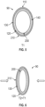
FIG. 5 shows an embodiment of a bead utilized in the configuration shown inFIGS. 2-4 , where the bead is in a normal state; -
FIG. 6 shows the bead ofFIG. 5 in a deformed state; -
FIG. 7 shows the lattice of beads ofFIG. 2 with top and bottom elastomer layers; -
FIG. 8 shows a plurality of the beads, from the lattice of beads ofFIG. 2 , with an elastomer segment extending from each bead, over an adjacent bead, to form a continuous elastomer boundary; -
FIG. 9 shows an alternate configuration of the section of the airfoil, having a base that defines voids, where ones of the voids are lined with the beads shown inFIGS. 2-4 , and a thermoelectric junction is formed either within at least one of the beads or around the base, and where the base is in a normal state; -
FIG. 10 shows the section ofFIG. 9 in a deformed state; -
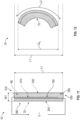
FIG. 11 shows another configuration of the section of the airfoil, having a base formed of a composition gradient defined by two material layers that extend alongside each other, where the two material layers have different CTEs selected to provide a predetermined deformation when subjected to heating, where a thermoelectric junction is formed between the two material layers, and where the section is in a normal state; -
FIG. 12 shows the section ofFIG. 11 in a deformed state; -
FIG. 13 shows an alternate configuration relative to the configuration ofFIG. 11 , where the composition gradient, formed of the two material layers, are formed of semicircular elements connected to one another, and where the section is in a normal state; -
FIG. 14 shows the section ofFIG. 13 in a deformed state; -
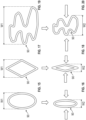
FIG. 15 shows an oval shaped bead, which may be utilized in the disclosed embodiments shown inFIGS. 2-10 , in a normal state; -
FIG. 16 shows the bead ofFIG. 15 in a deformed state; -
FIG. 17 shows a diamond shaped bead, which may be utilized in the disclosed embodiments shown inFIGS. 2-10 , in a normal state; -
FIG. 18 shows the bead ofFIG. 17 in a deformed state; -
FIG. 19 shows a random shaped bead, which may be utilized in the disclosed embodiments shown inFIGS. 2-10 , in a normal state; -
FIG. 20 shows the bead ofFIG. 17 in a deformed state; -
FIG. 21 shows an equivalent structure with a composition gradient formed of a plurality of materials having different coefficients of thermal expansion (CTE), at a temperature T1; and -
FIG. 22 shows the structure ofFIG. 21 at a temperature T2>T1. - A detailed description of one or more embodiments of the disclosed apparatus and method are presented herein by way of exemplification and not limitation with reference to the Figures.
-
FIG. 1A shows an aircraft 1 having afuselage 2 with a wing 3 andtail assembly 4, which may havecontrol surfaces 5. The wing 3 may include an engine 6, such as a gas turbine engine, and an auxiliary power unit 7 may be disposed at thetail assembly 4.FIG. 1B shows anairfoil 10 of the aircraft 1 according to an embodiment. Theairfoil 10 can be applied to fan blades, helicopter blades, rocket control surfaces, turbine blades, etc. The airfoil may have a leadingedge 10A, atrailing edge 10B, a chord extending 10C between the leading andtrailing edges airfoil skin 10D may define a first camber profile.FIG. 1C shows the same airfoil with a second camber profile, which is increased relative to the first camber profile, by pitching anaft portion 10E of the airfoil relative to aforward portion 10F. That is, apitch region 10G is located at an intersection between the forward andaft portions - In one embodiment, as shown in
FIG. 2 , theairfoil 10 may be additively manufactured with abase 70, utilized at least for thepitch region 10G of the airfoil ofFIGS. 1A-1B , formed to have a composition gradients across the hoop-shapedwalls 50, having anouter surface 52, aninner surface 54, to define first throughfourth perimeter segments segments outer boundary 80 and a lattice ofbeads 90 within theboundary 80. Thebeads 90 may have an oval cross section, though such shape is not intended on limiting the scope of the embodiments. - Each of the
beads 90 may have abead void 100 or cavity and may include the first andsecond perimeter segments beads 90 may include the third andfourth perimeter segments second perimeter segments beads 90 forms a circumferential (or perimeter) CTE gradient. - Adjacent ones of the
beads 90 may be interconnected with each other, e.g., along the perimeter segments 110-140. With this interconnected configuration, thebeads 90 form the lattice. - A
thermoelectric junction 150 may be disposed in one more of the bead voids 100, or may be disposed around theboundary 80 of thebase 70. Thethermoelectric junction 150 may form a Peltier or a Thomson device. For example, alternating P and N-type pillars made with materials with different Seebeck coefficients, or legs, are placed thermally in parallel to each other and electrically in series and joined with a thermally conducting plate on each side, e.g., ceramic, including acooling plate 160 and aheating plate 170. When a voltage is applied to the free ends of the two semiconductors, viaconnections 190 there is a flow of DC current across the junction of the semiconductors, causing a temperature difference. The side with thecooling plate 160 absorbs heat which is then transported by the semiconductor to the other side of the device. One of thecooling plate 160 orheating plate 170 may be exposed to the atmosphere if desired to bleed energy from it rather than directing energy from it back to theairfoil 10. - The
beads 90 may be formed of a bistable metal, alloy or composite. Thebeads 90 may be configured to change shape by a predetermined amount when subject to thermal input, e.g., heat, due to the second CTE obtained with the composition gradient. For example, when thebeads 90 are subject to thermal input from the thermoelectric junction 150 (FIG. 2 ), shape of the base 70 may change from a first state (FIG. 3 ) to a second state (FIG. 4 ). In the first state, thebase 70 may extend in a first direction (or length direction) to define a first length L1 and in a second direction (or width direction) to define a first width W1. In the second state the base 70 may extend in the first direction to define a second length L2 and in the second direction to define a second width W2. From the shape change, one of the first length and width L1, W1 may be greater or smaller than a corresponding one of the second length and width L2, W2. As shown inFIGS. 3 and 4 , the first width W1 is greater than the second width W2 and the first and second lengths L1, L2 are the same as each other. - As shown in
FIGS. 5 and 6 , in one embodiment, each perimeter segment 110-140 may have a radial inner portion 200 (the above noted inner surface 54) and a radial outer portion 210 (the above noted outer surface 52). It is to be appreciated that the use of the term radial in this context does not require a circular cross section but rather references a distance from a center of thebead 90. Theinner portion 200 of the first andsecond perimeter segments outer portion 210 of the first andsecond perimeter segments inner portion 200 of the third andfourth perimeter segments outer portion 210 of the third andfourth perimeter segments FIG. 5 shows thebead 90 in a first state when the thermoelectric junction 150 (FIG. 2 ) is not providing thermal input andFIG. 6 shows the bead in a second state whenthermoelectric junction 150 is providing thermal input. The embodiment shown inFIGS. 5 and 6 provides a radial CTE gradient that results in a tailored deformation of thebeads 90 upon receiving thermal input from thethermoelectric junction 150. - As shown in
FIG. 7 , theouter boundary 80 defines a firstouter end 230 and a secondouter end 240. The first and second outer ends 230, 240 are opposite each other. In one embodiment, atop elastomer layer 250 is disposed against thetop end 230 of theouter boundary 80 and abottom elastomer layer 260 is disposed against thebottom end 240 of theouter boundary 80. - As shown in
FIG. 8 , in one embodiment, anelastomer segment 270 extends from each of thebeads 90 disposed at theouter boundary 80 of the lattice ofbeads 90. With this configuration, adjacent ones of the elastomer segments overlap each other to define a flexible outer boundary cover. - Turning to
FIGS. 9 and 10 , in one embodiment, thebase 70 of theairfoil 10 may be manufactured with asupport structure 280 that may define theouter boundary 80 of thebase 70 and internal base voids 290 or cavities. Each of the base voids 290 may be lined with one of above disclosedbeads 90 and thus have a cavity surface 300 defining a cross sectional shape that is complementary to the shape of thebeads 90. Thesupport structure 280 may be formed of a support material that differs from the bead material. Anexterior surface 85, surrounding theouter boundary 80 of thebase 70, maybe be coated with the materials that form thebead 90. The support material may be an elastomer, a metal, an alloy or a composite. Athermoelectric junction 150 may be provided around theouter boundary 80 or in one or more of the bead voids 100. -
FIGS. 9 and 10 show the base 70 in the first state, having a first length and width L1, W1, and the second state, having a second length and width L2, W2. As indicated above, from the shape change, one of the first length and width L1, W1 may be greater or smaller than a corresponding one of the second length and width L2, W2. In the illustrated embodiment, the second width W2 is smaller than the first width W1 and the first and second lengths L1, L2 are the same as each other. -
FIGS. 11 and 12 show another embodiment in which theairfoil 10 may be additively manufactured to form abase 70 having a composition gradient. The composition gradient may define a first CTE, and a second CTE that differs from the first CTE. As indicated, this may be obtained from different metals (e.g., first and second materials corresponding to first and second metals) or from plastic, fillings, or fibers. Thebase 70 extends in a first direction (e.g., a length direction) fromfirst end 310 to asecond end 320 and in a second direction (e.g., a width direction) from afirst side 330 to a second side 34. Thebase 70 defines anouter boundary 80. The first CTE may be formed from afirst composition layer 350 that extends in the first direction between the first and second ends 310, 320, and in the second direction between the first side of thebase 70 and alayer junction 370. The second CTE may be formed in asecond composition layer 360 that extends in the first direction between the first and second ends 310, 320, and in the second direction between thesecond side 340 and thecomposition junction 370. That is, the first andsecond layers base 70. Athermoelectric junction 150 may extend along the first direction at thelayer junction 370, between the first and second composition layers 350, 360, or along theboundary 80 of thebase 70. - The first and second composition layers each may be a bistable metal, alloy or composite. The base 70 may extend in the first direction by a first length L1 and in the second direction by a first width W1. Due to the different coefficients of thermal expansion, when subjected to thermal input by the
thermoelectric junction 150, thebase 70 may deform as shown inFIG. 11 to form an arcuate shape. When in the deformed state, a longer side of the base 70 may have a length L2 that is greater than the first length L 1, though projected along first direction thebase 70 has a second length L2x that is shorter than the first length L1. The width may be unchanged. - As shown in
FIGS. 13 and 14 , between opposite ends 310, 320, in one embodiment the first and second layers form a chain ofelements 380 connected at circumferential ends 390, 400. Theelements 380 are illustrated as having a semicircular shape, though that is not intended on limiting the scope of the embodiments.FIG. 13 shows thebase 70 is in a normal state, having a first length L1.FIG. 14 shows the base 70 in a deformed state, from thermal input from thethermoelectric junction 150, having a second length L2 which is smaller than the first length L1. -
FIG. 15 shows an oval shapedbead 90, which may be formed as indicated above, in a normal state having a first width W1.FIG. 16 shows theoval bead 90 in a deformed state having a second width W2 that is less than the first width W1. As indicated, thebeads 90 do not need to be arcuate in shape.FIG. 17 shows a diamond shapedbead 90 in a normal state having a first width W1.FIG. 18 shows the diamond shapedbead 90 in a deformed state having a second width W2 that is less than the first width W1.FIG. 19 shows a random shapedbead 90 in a normal state having a first width W1.FIG. 20 shows the random shapedbead 90 in a deformed state having a second width W2 that is less than the first width W1. The desired deformation shape may determine the shape of thebead 90. -
FIGS. 21 and 22 show anequivalent structure 405 to the structures shown above and for example inFIGS. 11-12 . Specifically, the first and second composition layers 350, 360 are at a temperature T1 inFIG. 21 , and T2 that is greater than T1 inFIG. 22 . The controlled thermal expansion shown inFIG. 22 results from the composition layers being integrally connected. That is, the first and second composition layers 350, 360 bend together in a predictable and controlled way. That is, the controlled thermal expansion of the first and second composition layers 350, 360 in the disclose embodiments provides for controlled manipulation of the airfoil disclosed herein. - As can be appreciated, utilizing the above disclosed configurations to form the
airfoil 10, the camber of the airfoil may be selectively increased or decreased to change flow characteristics around it, e.g., to modify lift and drag, by applying thermal input to the materials, e.g., along theouter boundary 80 of the base 70 or, within one or more of the bead voids 100. That is, driving current across thethermoelectric junction 150 in a first direction may increase camber and driving the current across thethermoelectric junction 150 in a second direction may decrease camber. Thus, a controllable airfoil may be obtained without the need for a movable part. - The terminology used herein is for the purpose of describing particular embodiments only and is not intended to be limiting of the present disclosure. As used herein, the singular forms "a", "an" and "the" are intended to include the plural forms as well, unless the context clearly indicates otherwise. It will be further understood that the terms "comprises" and/or "comprising," when used in this specification, specify the presence of stated features, integers, steps, operations, elements, and/or airfoils, but do not preclude the presence or addition of one or more other features, integers, steps, operations, element airfoils, and/or groups thereof.
- Those of skill in the art will appreciate that various example embodiments are shown and described herein, each having certain features in the particular embodiments, but the present disclosure is not thus limited. Rather, the present disclosure can be modified to incorporate any number of variations, alterations, substitutions, combinations, sub-combinations, or equivalent arrangements not heretofore described, but which are commensurate with the scope of the present disclosure. Additionally, while various embodiments of the present disclosure have been described, it is to be understood that aspects of the present disclosure may include only some of the described embodiments. Accordingly, the present disclosure is not to be seen as limited by the foregoing description, but is only limited by the scope of the appended claims.
Claims (15)
- An airfoil comprising:a composition gradient defining a first coefficient of thermal expansion and a second coefficient of thermal expansion that differs from the first coefficient of thermal expansion; anda thermoelectric junction (150) operationally coupled to the composition gradient,wherein the composition gradient is formed of either of a plurality of dissimilar metals or of plastic with fillings or fibers.
- The airfoil of claim 1, comprising:
a base (70) formed by the composition gradient defining the first coefficient of thermal expansion and the second coefficient of thermal expansion that differs from the first coefficient of thermal expansion, so that:the base (70) defines an outer boundary (80) and beads (90) within the outer boundary (80),each of the beads (90) has a bead void, and each of the beads (90) includes:first and second perimeter segments that are opposite each other and formed to define the first CTE; andthird and fourth perimeter segments that are opposite each other, adjacent to the first and second perimeter segments, and formed to define the second CTE; andthe thermoelectric junction (150) is provided around the outer boundary (80) or in one or more of the bead voids. - The airfoil of claim 2, wherein:each perimeter segment has a radial inner portion and a radial outer portion;the radial inner portion of the first and second perimeter segments is formed of to define the first CTE and the radial outer portion of the first and second perimeter segments is formed to define the second CTE; andthe radial inner portion of the third and fourth perimeter segments is formed to define the second CTE and the radial outer portion of the third and fourth perimeter segments is formed to define of the first CTE.
- The airfoil of claim 2 or 3, wherein:
adjacent ones of the beads (90) are interconnected to form a lattice. - The airfoil of any of claims 2-4, wherein:the outer boundary (80) defines a first outer end and a second outer end, wherein the first and second outer ends are opposite each other, andthe base (70) includes a top elastomer layer that is disposed against the first outer end of the outer boundary (80) and a bottom elastomer layer that is disposed against the second outer end of the outer boundary (80).
- The airfoil of any of claims 2-5, wherein
the base (70) includes an elastomer segment that extends from each of the beads (90) that are located along the outer boundary (80) of the base (70), so that adjacent ones of the elastomer segments overlap each other to define a flexible outer boundary cover. - The airfoil of any of claims 2-6, wherein:
the base (70) includes a support material that forms a support structure that defines the outer boundary (80) of the base (70) and a plurality of base voids, wherein each of the plurality of base voids is lined with one of the beads (90). - The airfoil of claim 7, wherein:
the support material differs from the bead. - The airfoil of any of claims 2-8, wherein:
the beads (90) define an oval or diamond shape. - The airfoil of any of claims 2-9, wherein:
the thermoelectric junction (150) is a Peltier airfoil. - The airfoil of any of claims 2-10, wherein the composition gradient is formed of a first material having the first CTE and a second materials having the second CTE, and one or both of the first and second materials is a bistable metal, alloy or composite.
- The airfoil of claim 1, the comprising:
a base (70) defining a first CTE, and a second CTE that differs from the first CTE, wherein the base (70) defines an outer boundary (80) and extends in a first direction from first end to a second end and in a second direction from a first side to a second side, so that:a first layer extends in the first direction between the first and second ends to define the first CTE;a second layer extends in the first direction between the first and second ends to define the second CTE, wherein a layer junction is defined between the first and second layers; anda thermoelectric junction (150) extends along the layer junction or the outer boundary (80). - The airfoil of claim 12, wherein:
the base (70) includes a chain of connected elements, and optionally wherein:
the elements define an arcuate shape. - The airfoil of claim 12 or 13, wherein:
one or both of the first and second layers are formed of first and second materials, one or both of which is a bistable metal, alloy or composite. - The airfoil of any of claims 12-14, wherein:
the thermoelectric junction (150) is a Peltier airfoil.
Applications Claiming Priority (1)
| Application Number | Priority Date | Filing Date | Title |
|---|---|---|---|
| US18/464,159 US12384515B2 (en) | 2023-09-08 | 2023-09-08 | Airfoil formed of thermally adaptive materials and a thermoelectric junction |
Publications (1)
| Publication Number | Publication Date |
|---|---|
| EP4520656A1 true EP4520656A1 (en) | 2025-03-12 |
Family
ID=92538454
Family Applications (1)
| Application Number | Title | Priority Date | Filing Date |
|---|---|---|---|
| EP24196309.9A Pending EP4520656A1 (en) | 2023-09-08 | 2024-08-23 | Airfoil formed of thermally adaptive materials and a thermoelectric junction |
Country Status (2)
| Country | Link |
|---|---|
| US (1) | US12384515B2 (en) |
| EP (1) | EP4520656A1 (en) |
Families Citing this family (1)
| Publication number | Priority date | Publication date | Assignee | Title |
|---|---|---|---|---|
| US20250084834A1 (en) * | 2023-09-08 | 2025-03-13 | Hamilton Sundstrand Corporation | Aircraft flow control device formed of thermally adaptive materials and a thermoelectric junction |
Citations (3)
| Publication number | Priority date | Publication date | Assignee | Title |
|---|---|---|---|---|
| US6100463A (en) * | 1997-11-18 | 2000-08-08 | The Boeing Company | Method for making advanced thermoelectric devices |
| EP2974954A1 (en) * | 2014-07-16 | 2016-01-20 | The Boeing Company | Adaptive composite structure using shape memory alloys |
| EP4177440A1 (en) * | 2021-11-05 | 2023-05-10 | Hamilton Sundstrand Corporation | Articles having thermally controlled microstructure and methods of manufacture thereof |
Family Cites Families (106)
| Publication number | Priority date | Publication date | Assignee | Title |
|---|---|---|---|---|
| US3326726A (en) * | 1963-03-22 | 1967-06-20 | Gen Motors Corp | Thermoelectric array and method of manufacture |
| DE2737248C2 (en) | 1977-08-18 | 1985-09-19 | MTU Motoren- und Turbinen-Union München GmbH, 8000 München | High strength component with a complex geometric shape and process for its manufacture |
| US4851285A (en) * | 1984-03-12 | 1989-07-25 | Brotz Gregory R | Cellular carbon structure and method for producing same |
| CA1322876C (en) | 1986-01-22 | 1993-10-12 | Tadao Inabata | Light metallic composite material and method of producing thereof |
| US5230850A (en) | 1991-05-16 | 1993-07-27 | Lewis Raymond O | Fan blade reinforcement using bonded hollow spheres |
| US6161382A (en) | 1992-07-30 | 2000-12-19 | Brotz; Gregory R. | Thermoelectric actuator |
| DE4338457C2 (en) * | 1993-11-11 | 1998-09-03 | Mtu Muenchen Gmbh | Component made of metal or ceramic with a dense outer shell and porous core and manufacturing process |
| US6499952B1 (en) | 1997-02-28 | 2002-12-31 | The Boeing Company | Shape memory alloy device and control method |
| DE19742314C2 (en) | 1997-09-25 | 2000-06-21 | Daimler Chrysler Ag | Supporting structure |
| US6211598B1 (en) | 1999-09-13 | 2001-04-03 | Jds Uniphase Inc. | In-plane MEMS thermal actuator and associated fabrication methods |
| DE10250758A1 (en) | 2002-10-31 | 2004-05-13 | Martin Weicker | Thermomechanical micro-valve with state signaling has dual stable state bi-metallic or shape memory alloy snap element in hollow volume between circuit boards joined e.g. by multilayering or adhesive |
| US7579069B2 (en) | 2003-11-06 | 2009-08-25 | International Business Machines Corporation | Negative coefficient of thermal expansion particles and method of forming the same |
| US7059664B2 (en) | 2003-12-04 | 2006-06-13 | General Motors Corporation | Airflow control devices based on active materials |
| US7721762B2 (en) | 2004-06-24 | 2010-05-25 | The Aerospace Corporation | Fast acting valve apparatuses |
| US7650910B2 (en) | 2004-06-24 | 2010-01-26 | The Aerospace Corporation | Electro-hydraulic valve apparatuses |
| US7686040B2 (en) | 2004-06-24 | 2010-03-30 | The Aerospace Corporation | Electro-hydraulic devices |
| US7854467B2 (en) | 2004-11-05 | 2010-12-21 | General Motors Corporation | Airflow control devices based on active materials |
| JP2007023361A (en) | 2005-07-20 | 2007-02-01 | Mitsubishi Engineering Plastics Corp | Method for plating aromatic polycarbonate resin molded product and plated molded product |
| US7913928B2 (en) | 2005-11-04 | 2011-03-29 | Alliant Techsystems Inc. | Adaptive structures, systems incorporating same and related methods |
| GB0525799D0 (en) * | 2005-12-20 | 2006-01-25 | Rolls Royce Plc | Lightweight components |
| TW200728605A (en) | 2006-01-20 | 2007-08-01 | Univ Tamkang | Thermo-buckled micro-actuator unit made of polymer with high thermal expansion coefficient |
| GB0601220D0 (en) * | 2006-01-21 | 2006-03-01 | Rolls Royce Plc | Aerofoils for gas turbine engines |
| US20070184238A1 (en) | 2006-02-06 | 2007-08-09 | Energy Related Devices, Inc. | Laminate actuators and valves |
| WO2008035293A2 (en) | 2006-09-20 | 2008-03-27 | Koninklijke Philips Electronics N.V. | A micro-fluidic device for the use in biochips or biosystems |
| US7770959B2 (en) | 2006-10-30 | 2010-08-10 | Gm Global Technology Operations, Inc. | Door actuation systems using active materials |
| US20080236668A1 (en) | 2007-03-26 | 2008-10-02 | Timothy Beerling | Microfluidic Valve |
| US20080302024A1 (en) | 2007-06-05 | 2008-12-11 | Gm Global Technology Operations, Inc. | Tunable impedance load-bearing structures |
| US7967570B2 (en) | 2007-07-27 | 2011-06-28 | United Technologies Corporation | Low transient thermal stress turbine engine components |
| US7967568B2 (en) | 2007-09-21 | 2011-06-28 | Siemens Energy, Inc. | Gas turbine component with reduced cooling air requirement |
| US8247050B2 (en) | 2009-06-02 | 2012-08-21 | Integran Technologies, Inc. | Metal-coated polymer article of high durability and vacuum and/or pressure integrity |
| GB2472053A (en) | 2009-07-23 | 2011-01-26 | Rolls Royce Plc | Aircraft and engine deicing apparatus |
| JP2011148037A (en) | 2010-01-21 | 2011-08-04 | Tokai Rubber Ind Ltd | Actuator using shape memory polymer, and method of controlling the same |
| US8966887B2 (en) | 2011-04-08 | 2015-03-03 | GM Global Technology Operations LLC | Reconfigurable bi-metallic mixer for an exhaust aftertreatment system and method of using the same |
| US9796159B2 (en) | 2011-04-14 | 2017-10-24 | The United States Of America As Represented By The Administrator Of Nasa | Electric field activated shape memory polymer composite |
| KR101333048B1 (en) | 2011-07-08 | 2013-11-26 | 울산대학교 산학협력단 | Actuator using shape memory alloy |
| IL221669A0 (en) | 2011-08-28 | 2012-12-31 | Heliofocus Ltd | Fluid transfer assembly |
| US20130255796A1 (en) | 2012-03-30 | 2013-10-03 | General Electric Company | Flow-control device, component having a flow-control device, and method of producing a flow-control device |
| DE102012205262B4 (en) | 2012-03-30 | 2024-09-26 | Ford Global Technologies, Llc | Variable flow resistance |
| US9470234B2 (en) * | 2012-04-26 | 2016-10-18 | Hamilton Sundstrand Corporation | Compressor housing bearing and seal |
| US9181933B2 (en) | 2012-12-10 | 2015-11-10 | Alcatel Lucent | Temperature control device with a passive thermal feedback control valve |
| US9650898B2 (en) | 2012-12-27 | 2017-05-16 | United Technologies Corporation | Airfoil with variable profile responsive to thermal conditions |
| US9328734B2 (en) | 2012-12-28 | 2016-05-03 | Hamilton Sundstrand Corporation | Seal plate |
| US9631268B2 (en) * | 2013-02-26 | 2017-04-25 | The Boeing Company | Methods and systems for shape memory alloy structures |
| JP6058809B2 (en) | 2013-06-28 | 2017-01-11 | ヘルムホルツ−ツェントルム ゲーストハハト ツェントルム フュアー マテリアル ウント キュステンフォルシュンク ゲーエムベーハー | Method for making bidirectional shape memory actuator and method of using the same |
| WO2015006428A1 (en) | 2013-07-09 | 2015-01-15 | United Technologies Corporation | Interlocked plated polymers |
| EP3019723A4 (en) | 2013-07-09 | 2017-05-10 | United Technologies Corporation | Plated polymer compressor |
| US9103568B2 (en) | 2013-08-02 | 2015-08-11 | Hamilton Sundstrand Corporation | Compressor housing for an air cycle machine |
| US9649690B2 (en) | 2014-02-25 | 2017-05-16 | General Electric Company | System having layered structure and method of making the same |
| DE102014107821A1 (en) | 2014-06-04 | 2015-12-17 | G. Rau Gmbh & Co. Kg | Thermal actuator made of a shape memory alloy |
| US9719536B2 (en) * | 2014-07-03 | 2017-08-01 | The Boeing Company | Assemblies including shape memory alloy fittings and composite structural members |
| CN105336843B (en) | 2014-07-23 | 2018-10-02 | 清华大学 | Electric heating actuator |
| DE102014225229A1 (en) | 2014-12-09 | 2016-06-23 | Robert Bosch Gmbh | Thermomechanical device and method of making same |
| US9757936B2 (en) | 2014-12-29 | 2017-09-12 | General Electric Company | Hot gas path component |
| WO2016141033A1 (en) | 2015-03-02 | 2016-09-09 | Board Of Regents, The University Of Texas System | Systems and methods for thermally actuated flow control |
| EP3112055B1 (en) | 2015-07-01 | 2020-12-02 | Ansaldo Energia IP UK Limited | Method for manufacturing a metal part with bi-metallic characteristic |
| US10053239B2 (en) * | 2015-09-09 | 2018-08-21 | The Boeing Company | Thermally graded adaptive multifunctional cellular structures with shape memory alloys |
| US9784126B2 (en) | 2015-12-14 | 2017-10-10 | Hamilton Sundstrand Corporation | Variable-sized cooling air flow path |
| TWI598031B (en) | 2016-02-05 | 2017-09-01 | 緯創資通股份有限公司 | Noise suppression apparatus and fan module using the same |
| US9897078B2 (en) | 2016-05-24 | 2018-02-20 | The Boeing Company | Bi-directional rotary shape memory alloy element actuator assemblies, and systems and methods including the same |
| US10473093B2 (en) * | 2016-08-26 | 2019-11-12 | Daegu Gyeongbuk Institute Of Science And Technology | Soft actuator using thermoelectric effect |
| US11008943B2 (en) | 2016-08-31 | 2021-05-18 | Unison Industries, Llc | Fan casing assembly with cooler and method of moving |
| DE102016224979A1 (en) * | 2016-12-14 | 2018-06-14 | Robert Bosch Gmbh | Electrically controllable adjustment device |
| US10533558B2 (en) | 2016-12-21 | 2020-01-14 | Saudi Arabian Oil Company | Centrifugal pump with adaptive pump stages |
| CA3097190A1 (en) | 2017-06-14 | 2018-12-20 | The Royal Institution For The Advancement Of Learning/Mcgill University | Lattice metamaterial having programed thermal expansion |
| US10731666B2 (en) | 2017-10-27 | 2020-08-04 | Rolls-Royce North American Technologies Inc. | Impeller shroud with closed form refrigeration system for clearance control in a centrifugal compressor |
| CN110100385A (en) | 2017-11-27 | 2019-08-06 | 松下知识产权经营株式会社 | Actuator devices |
| WO2019108203A1 (en) | 2017-11-30 | 2019-06-06 | Siemens Aktiengesellschaft | Hybrid ceramic matrix composite components with intermediate cushion structure |
| KR102440610B1 (en) | 2017-12-29 | 2022-09-05 | 현대자동차 주식회사 | Composition of complex materail |
| US10710160B2 (en) * | 2018-01-08 | 2020-07-14 | Hamilton Sundstrand Corporation | Shrouded rotor and a hybrid additive manufacturing process for a shrouded rotor |
| WO2019162754A1 (en) | 2018-02-20 | 2019-08-29 | King Abdullah University Of Science And Technology | Solar-actuated energy harvesting device and method |
| EP3784822A1 (en) | 2018-04-24 | 2021-03-03 | CSEM Centre Suisse d'Electronique et de Microtechnique SA - Recherche et Développement | Method of metal plating of polymer-containing substrates |
| US11167836B2 (en) | 2018-06-21 | 2021-11-09 | Sierra Nevada Corporation | Devices and methods to attach composite core to a surrounding structure |
| US11453197B2 (en) | 2018-07-03 | 2022-09-27 | Hamilton Sundstrand Corporation | Antimicrobial surfaces for flow path components |
| US10976119B2 (en) | 2018-07-30 | 2021-04-13 | The Boeing Company | Heat transfer devices and methods of transfering heat |
| US11167482B2 (en) | 2018-10-19 | 2021-11-09 | Hewlett-Packard Development Company, L.P. | Three-dimensional printing |
| US11192333B2 (en) | 2018-10-25 | 2021-12-07 | Honda Motor Co., Ltd. | Embedded metal transition for joining fiber reinforced polymers and metallic structures |
| US10982783B2 (en) | 2018-10-30 | 2021-04-20 | Hamilton Sunstrand Corporation | Variable flow controlled diaphragm valve based on shape memory alloy |
| JP7314272B2 (en) | 2018-12-11 | 2023-07-25 | ゼネラル・エレクトリック・カンパニイ | Distributed nested cell damping system |
| US20200316684A1 (en) | 2019-04-05 | 2020-10-08 | Rolls-Royce Corporation | Additive manufactured alloy components |
| US11359287B2 (en) | 2019-08-01 | 2022-06-14 | The Boeing Company | Adhesion between polymer substrates and autocatalytic plates |
| EP4007688B1 (en) | 2019-08-02 | 2026-05-06 | Airtech International, Inc. | Adjustable cte polymer compositions for extrusion and additive manufacturing processes |
| US11643566B2 (en) | 2019-09-09 | 2023-05-09 | Xerox Corporation | Particulate compositions comprising a metal precursor for additive manufacturing and methods associated therewith |
| TWI714279B (en) | 2019-09-24 | 2020-12-21 | 丁原傑 | Temperature compensation current limiting device and elastic infusion system |
| US11131339B1 (en) | 2020-03-04 | 2021-09-28 | The Boeing Company | High performance air journal bearing |
| US11802736B2 (en) | 2020-07-29 | 2023-10-31 | Hamilton Sundstrand Corporation | Annular heat exchanger |
| US11692049B2 (en) | 2020-09-18 | 2023-07-04 | Ford Global Technologies, Llc | Additively manufactured thermoset polymers for metal plating and metal plated parts formed therefrom |
| US11248592B1 (en) | 2021-03-26 | 2022-02-15 | Toyota Motor Engineering & Manufacturing North America, Inc. | Shape memory alloy enhanced bi-stable actuator |
| US11994141B2 (en) | 2021-09-10 | 2024-05-28 | Hamilton Sundstrand Corporation | Turbomachinery shaft with variable lattice densities |
| US11802488B2 (en) | 2021-09-10 | 2023-10-31 | Hamilton Sundstrand Corporation | Turbomachinery seal plate with variable lattice densities |
| US11668316B1 (en) | 2022-01-07 | 2023-06-06 | Hamilton Sundstrand Corporation | Rotor formed of multiple metals |
| US20230233342A1 (en) | 2022-01-27 | 2023-07-27 | Hamilton Sundstrand Corporation | Articles having thermally controlled microstructure and methods of manufacture thereof |
| US11970951B1 (en) | 2023-02-01 | 2024-04-30 | Hamilton Sundstrand Corporation | Metal plated additively manufactured plastic rotors and their method of manufacturing |
| US20250033270A1 (en) | 2023-07-24 | 2025-01-30 | Hamilton Sundstrand Corporation | Metal plated additively manufactured plastic acm rotors with internal thermally adaptive structure |
| US20250033271A1 (en) | 2023-07-24 | 2025-01-30 | Hamilton Sundstrand Corporation | Metal plated additively manufactured plastic acm housings with internal thermally adaptive structure |
| US20250033796A1 (en) | 2023-07-24 | 2025-01-30 | Hamilton Sundstrand Corporation | Metal plating retention on additively manufacture plastic parts for an aircraft |
| US20250033282A1 (en) | 2023-07-24 | 2025-01-30 | Hamilton Sundstrand Corporation | Metal plated additively manufactured plastic acm shrouds with internal thermally adaptive structure |
| US20250033272A1 (en) | 2023-07-24 | 2025-01-30 | Hamilton Sundstrand Corporation | Metal plated additively manufactured plastic acm shafts with internal thermally adaptive structure |
| US20250033283A1 (en) | 2023-07-24 | 2025-01-30 | Hamilton Sundstrand Corporation | Metal plated additively manufactured plastic acm seal plates with internal thermally adaptive structure |
| US12162606B1 (en) * | 2023-09-08 | 2024-12-10 | Hamilton Sundstrand Corporation | Metal plated plastic ACM part with internal thermally adaptive structure |
| US20250089568A1 (en) | 2023-09-08 | 2025-03-13 | Hamilton Sundstrand Corporation | Actuator formed of thermally adaptive material and a thermoelectric junction |
| US20250084766A1 (en) | 2023-09-08 | 2025-03-13 | Hamilton Sundstrand Corporation | Aircraft airfoil formed from thermally adaptive materials and including damping element, stiffening element, and a thermoelectric junction |
| US20250084833A1 (en) | 2023-09-08 | 2025-03-13 | Hamilton Sundstrand Corporation | Aircraft component additively having thermally adaptive material and a thermoelectric junction |
| US20250084834A1 (en) | 2023-09-08 | 2025-03-13 | Hamilton Sundstrand Corporation | Aircraft flow control device formed of thermally adaptive materials and a thermoelectric junction |
| US20250088125A1 (en) | 2023-09-08 | 2025-03-13 | Hamilton Sundstrand Corporation | Aircraft actuator formed of thermally adaptive materials and a thermoelectric junction |
| US20250084859A1 (en) | 2023-09-08 | 2025-03-13 | Hamilton Sundstrand Corporation | Compressor shroud with controllable bypass component formed of thermally adaptive materials and a thermoelectric junction |
| US20250085725A1 (en) | 2023-09-08 | 2025-03-13 | Hamilton Sundstrand Corporation | Flow control device formed of thermally adaptive material and a thermoelectric junction |
-
2023
- 2023-09-08 US US18/464,159 patent/US12384515B2/en active Active
-
2024
- 2024-08-23 EP EP24196309.9A patent/EP4520656A1/en active Pending
Patent Citations (3)
| Publication number | Priority date | Publication date | Assignee | Title |
|---|---|---|---|---|
| US6100463A (en) * | 1997-11-18 | 2000-08-08 | The Boeing Company | Method for making advanced thermoelectric devices |
| EP2974954A1 (en) * | 2014-07-16 | 2016-01-20 | The Boeing Company | Adaptive composite structure using shape memory alloys |
| EP4177440A1 (en) * | 2021-11-05 | 2023-05-10 | Hamilton Sundstrand Corporation | Articles having thermally controlled microstructure and methods of manufacture thereof |
Also Published As
| Publication number | Publication date |
|---|---|
| US20250083795A1 (en) | 2025-03-13 |
| US12384515B2 (en) | 2025-08-12 |
Similar Documents
| Publication | Publication Date | Title |
|---|---|---|
| US8382042B2 (en) | Structure with reconfigurable polymer material | |
| JP6675755B2 (en) | Engine heat exchanger and method of forming | |
| US12384515B2 (en) | Airfoil formed of thermally adaptive materials and a thermoelectric junction | |
| US9284914B2 (en) | Variable geometry structure | |
| US20080035788A1 (en) | Cellular support structures used for controlled actuation of fluid contact surfaces | |
| EP4520965A1 (en) | Aircraft actuator formed of thermally adaptive materials and a thermoelectric junction | |
| EP3147208B1 (en) | Thermal actuation of riblets | |
| EP3068974B1 (en) | Turbine components with negative cte features | |
| EP4520981A1 (en) | Aircraft flow control device formed of thermally adaptive materials and a thermoelectric junction | |
| EP4520967A1 (en) | Compressor shroud with controllable bypass component formed of thermally adaptive materials and a thermoelectric junction | |
| US20250084766A1 (en) | Aircraft airfoil formed from thermally adaptive materials and including damping element, stiffening element, and a thermoelectric junction | |
| ES2987519T3 (en) | Aerodynamic profile of an airfoil | |
| CA2948252A1 (en) | Turbine airfoil with passive morphing structure | |
| EP4528101A1 (en) | Aircraft component additively having thermally adaptive material and a thermoelectric junction | |
| EP4520964A1 (en) | Actuator formed of thermally adaptive material and a thermoelectric junction | |
| EP4530436A2 (en) | Flow control device formed of thermally adaptive material and a thermoelectric junction | |
| JP6924033B2 (en) | Solid-state motors and related systems and methods | |
| EP3643617B1 (en) | Heater design for carbon allotrope ice protection systems | |
| EP4520966A1 (en) | Locking device formed of thermally adaptive multi-metallic material and a thermoelectric junction and method of manufacturing the same | |
| EP4520657A1 (en) | Aircraft airfoil formed from thermally adaptive materials and including damping element, stiffening element, and a thermoelectric junction | |
| EP4220061B1 (en) | Smart additively manufactured heat exchanger with adaptive profile and turbulator | |
| US20100041778A1 (en) | Reconfigurable polymeric foam structure | |
| US12635412B2 (en) | Locking device formed of thermally adaptive multi-metallic material and a thermoelectric junction and method of manufacturing the same | |
| EP4610025A1 (en) | Thermally adaptive insulation | |
| EP4610507A1 (en) | Thermally adaptive gas bearing sleeve configured for remote geometry control |
Legal Events
| Date | Code | Title | Description |
|---|---|---|---|
| PUAI | Public reference made under article 153(3) epc to a published international application that has entered the european phase |
Free format text: ORIGINAL CODE: 0009012 |
|
| STAA | Information on the status of an ep patent application or granted ep patent |
Free format text: STATUS: THE APPLICATION HAS BEEN PUBLISHED |
|
| AK | Designated contracting states |
Kind code of ref document: A1 Designated state(s): AL AT BE BG CH CY CZ DE DK EE ES FI FR GB GR HR HU IE IS IT LI LT LU LV MC ME MK MT NL NO PL PT RO RS SE SI SK SM TR |
|
| STAA | Information on the status of an ep patent application or granted ep patent |
Free format text: STATUS: REQUEST FOR EXAMINATION WAS MADE |
|
| 17P | Request for examination filed |
Effective date: 20250908 |
|
| GRAP | Despatch of communication of intention to grant a patent |
Free format text: ORIGINAL CODE: EPIDOSNIGR1 |
|
| STAA | Information on the status of an ep patent application or granted ep patent |
Free format text: STATUS: GRANT OF PATENT IS INTENDED |