EP4520650A1 - Boat propulsion device and boat - Google Patents
Boat propulsion device and boat Download PDFInfo
- Publication number
- EP4520650A1 EP4520650A1 EP24193091.6A EP24193091A EP4520650A1 EP 4520650 A1 EP4520650 A1 EP 4520650A1 EP 24193091 A EP24193091 A EP 24193091A EP 4520650 A1 EP4520650 A1 EP 4520650A1
- Authority
- EP
- European Patent Office
- Prior art keywords
- propulsion device
- cover
- boat
- boat propulsion
- connecting part
- Prior art date
- Legal status (The legal status is an assumption and is not a legal conclusion. Google has not performed a legal analysis and makes no representation as to the accuracy of the status listed.)
- Granted
Links
Images








Classifications
-
- B—PERFORMING OPERATIONS; TRANSPORTING
- B63—SHIPS OR OTHER WATERBORNE VESSELS; RELATED EQUIPMENT
- B63H—MARINE PROPULSION OR STEERING
- B63H20/00—Outboard propulsion units, e.g. outboard motors or Z-drives; Arrangements thereof on vessels
- B63H20/32—Housings
-
- B—PERFORMING OPERATIONS; TRANSPORTING
- B63—SHIPS OR OTHER WATERBORNE VESSELS; RELATED EQUIPMENT
- B63H—MARINE PROPULSION OR STEERING
- B63H21/00—Use of propulsion power plant or units on vessels
- B63H21/12—Use of propulsion power plant or units on vessels the vessels being motor-driven
- B63H21/17—Use of propulsion power plant or units on vessels the vessels being motor-driven by electric motor
Definitions
- the present invention disclosed herein relates to a boat propulsion device and a boat.
- outboard motors are known in which an internal structure such as an engine is covered by a plurality of covers (see, e.g. JP 2022-104230 A , JP 2019-10992 A , JP 2019-10993 A ).
- the plurality of covers includes an upper cover and a pair of facing covers.
- the pair of facing covers are arranged to face each other through the internal structure to form an opening that exposes the upper portion of the internal structure.
- the upper cover is arranged to cover the opening.
- said object is solved by a boat propulsion device having the features of independent claim 1. Moreover, said object is also solved by a boat according to claim 15. Preferred embodiments are laid down in the dependent claims.
- a boat propulsion device disclosed herein includes: an internal structure; a pair of facing covers arranged to face each other through the internal structure in a first direction along a horizontal direction to form an opening to expose an upper portion of the internal structure; a connecting part extending in the first direction and connecting the pair of facing covers together; and an upper cover covering the opening and having a hook that engages the connecting part.
- the hook of the upper cover engages the connecting part that connects the pair of facing covers, so that the pair of facing covers and the upper cover can be aligned and positioned with high precision.
- the above boat propulsion device may be configured such that the connecting part is provided on the respective facing walls of the pair of facing covers, the hook is provided on the lower surface of the upper cover, and the engaged portion between the connecting part and the hook are covered by the pair of facing covers and the upper cover. According to this boat propulsion device, the engaged portion between the connecting part and the hook is not exposed to the outside, which improves the design of the appearance of the boat propulsion device.
- the above boat propulsion device may be configured such that the upper cover is configured to pivot about the connecting part, displaceable between a closed position that covers the opening and an opened position that opens at least a portion of the opening, and detachable from the pair of facing covers.
- the upper cover can be easily displaced to the closed position and to the opened position by pivoting about the connecting part, while maintaining the positional relationship of the three covers.
- only the upper cover can be removed to perform work (such as maintenance) on the internal structure.
- the above boat propulsion device may be configured such that one of the upper cover and the facing cover is provided with a recess formed thereon, and the other of the upper cover and the facing cover is provided with a protrusion which is inserted into the recess when the upper cover is in the closed position and is released from the recess when the upper cover is in the opened position. According to this boat propulsion device, when the upper cover is in the closed position, the protrusion is inserted into the recess, thereby enabling the three covers to be aligned and positioned with greater precision.
- the above boat propulsion device may be configured such that an elastic member is disposed between the connecting part and the hook. According to this boat propulsion device, the rattling of the upper cover against the facing covers can be suppressed, and vibration can be absorbed.
- the above boat propulsion device may be configured such that the internal structure includes at least one of a control unit and a drive source, the boat propulsion device further includes a first fixing member that fixes the pair of facing covers to the internal structure, and the upper cover covers the first fixing member.
- the upper cover can be positioned with respect to the facing covers through the internal structure.
- the first fixing member is not exposed to the outside, which improves the design of the appearance of the boat propulsion device.
- the above boat propulsion device may be configured such that the upper cover has a lower edge that is spaced apart from the pair of facing covers. According to this boat propulsion device, it is possible to suppress the direct influence of deformation of the upper cover on the facing covers.
- the above boat propulsion device may be configured such that the internal structure is provided with a hang tab at a position that is exposed to the opening. According to this boat propulsion device, the hang tab can be used to lift up the boat propulsion device by removing only the upper cover.
- the above boat propulsion device may be configured such that the hang tab has a hanging portion that protrudes upwardly from the opening. According to this boat propulsion device, e.g., a boat propulsion device in a lying down state can be lifted up using the hang tab.
- the above boat propulsion device may be configured such that each of the facing covers has a contact portion that contacts the hook in the first direction. According to this boat propulsion device, misalignment of the upper cover with respect to the pair of facing covers in the first direction can be suppressed.
- the above boat propulsion device may be configured such that the connecting part is located at the rear end side of the upper cover, and the boat propulsion device further includes a second fixing member that fixes the front end side of the upper cover to the internal structure.
- the rear end side of the upper cover is positioned with respect to the facing covers by the hook while the front end side of the upper cover is fixed by the second fixing member.
- the above boat propulsion device may be configured such that the connecting part includes a cylinder provided on one of the two facing covers and an insert provided on the other of the two facing covers that is inserted into the cylinder. According to this boat propulsion device, misalignment between the pair of facing covers can be effectively suppressed.
- the above boat propulsion device may be configured such that the hook engages a portion of the connecting part where the insert is inserted into the cylinder. According to this boat propulsion device, the load from the hook can be distributed by the pair of facing covers.
- a boat propulsion device disclosed herein includes: an internal structure; a pair of facing covers arranged to face each other through the internal structure in a first direction to form an opening to expose one side of the internal structure in a second direction perpendicular to the first direction; a connecting part extending in the first direction and connecting the pair of facing covers together; and a cover covering the opening and having a hook that engage the connecting part.
- the hook of the cover engages the connecting part that connects the pair of facing covers, so that the pair of facing covers and the cover can be aligned and positioned with high precision.
- the technology disclosed herein can be implemented in various forms, e.g., in the form of an outboard motor, a boat propulsion device, a boat equipped with a boat propulsion device, and a method for aligning a plurality of covers.
- a pair of facing covers and a cover can be aligned and positioned with high accuracy.
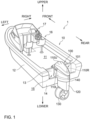
- FIG. 1 is a perspective view schematically illustrating the configuration of a boat 1 in this embodiment.
- FIG. 1 and other drawings described below show arrows representing each direction with respect to the position of the boat 1. More specifically, each figure shows arrows representing front (FRONT), rear (REAR), left (LEFT), right (RIGHT), upper (UPPER), and lower (LOWER) directions, respectively.
- the front-rear direction, left-right direction, and upper-lower direction (vertical direction) are orthogonal to each other.
- the boat 1 is equipped with a hull 10 and an electric propulsion device 100.
- the electric propulsion device 100 is an example of the boat propulsion device.
- the hull 10 is a part of the boat 1 for occupants to ride. As shown in FIG. 1 , the hull 10 has a hull body 12 having a living space 11, a pilot seat 16 installed in the living space 11, and an operating device 17 installed near the pilot seat 16.
- the operating device 17 is a device for maneuvering the boat and includes, e.g., a steering wheel, a shift throttle lever, a joystick, a monitor, and an input device.
- the hull 10 also has a partition wall 13 that partitions the rear end of the living space 11 and a transom 14 positioned at the rear end of the hull 10. In the front-rear direction, a space 15 exists between the transom 14 and the partition wall 13.
- FIG. 2 is a side view schematically illustrating a configuration of an electric propulsion device 100.
- the electric propulsion device 100 is a device that generates thrust to propel the boat 1.
- the electric propulsion device 100 is an electric propulsion device driven by an electric motor (an example of the drive source).
- the electric propulsion device 100 in the reference attitude will be described unless otherwise specified.
- the reference attitude is the attitude of the electric propulsion device 100 when the boat 1 is running (attitude shown in FIG. 1 ) and is the attitude in which the propeller rotation axis L of the propeller 132 (described below) extends in the front-rear direction.
- the front-rear direction, the left-right direction, and the upper-lower direction are defined on the basis of the electric propulsion device 100 in the reference attitude.
- the electric propulsion device 100 is attached to a transom 14 disposed at the rear (stern) of the hull 10 (see FIG. 1 ). As shown in FIG. 2 , the electric propulsion device 100 has a propulsion device main body 101 and a suspension device 102.
- the suspension device 102 is a device for suspending the propulsion device main body 101 to the hull 10.
- the suspension device 102 includes a tilt shaft 104, a pair of left and right clamp brackets 106, and a connection bracket 109 (see FIG. 5 below).
- the pair of left and right clamp brackets 106 are disposed behind the hull 10 in a state separated from each other in the left-right direction and fixed to the transom 14 of the hull 10 by using, e.g., bolts.
- Each clamp bracket 106 has a cylindrical supporting portion 106a with a through-hole extending in the left-right direction.
- the tilt shaft 104 is a rod-shaped member.
- the tilt shaft 104 is rotatably supported in the through-hole of the supporting portion 106a of the clamp bracket 106.
- the tilt axis At which is the center line of the tilt shaft 104, constitutes an axis in the horizontal direction (left-right direction) in the tilting action of the electric propulsion device 100.
- connection bracket 109 is disposed so as to be sandwiched between the pair of clamp brackets 106 in the left-right direction and is supported by the supporting portion 106a of the clamp brackets 106 via the tilt shaft 104 in such a manner that the connection bracket 109 can rotate about the tilt axis At.
- the connection bracket 109 is fixed to the base of the propulsion device main body 101 (not shown).
- the connection bracket 109 is driven to pivot about the tilt axis At with respect to the clamp bracket 106 by a tilt device (not shown) including an actuator such as a hydraulic cylinder.
- the propulsion device main body 101 fixed to the connection bracket 109 also rotates about the tilt axis At. This achieves the tilting action of rotating the propulsion device main body 101 in the upper-lower direction with respect to the hull 10.
- the electric propulsion device 100 can change the angle about the tilt axis At of the propulsion device main body 101 in the range from the tilt-down state in which the propeller 132 is in the water (the state in which the electric propulsion device 100 is in the reference attitude: the state shown in FIG. 2 ) to tilt-up state in which the propeller 132 is located above the waterline. Trimming action for adjusting the attitude of the boat 1 during travel can also be performed by adjusting the angle around the tilt axis At of the propulsion device main body 101.
- the propulsion device main body 101 includes a cowl 110, a middle housing 140, a lower housing 120, a duct 122, and a drive unit 130.
- An internal structure 300 (e.g., see FIG. 10 below) is disposed on a base fixed to the connection bracket 109 of the suspension device 102.
- the internal structure 300 is a structure located at the upper portion of the electric propulsion device 100 (propulsion device main body 101), in other words, a structure of a portion exposed to the outside when the upper cover 110U described below is removed.
- the internal structure 300 includes a motor control unit (MCU) that controls the electric motor 134 and gear mechanism described below.
- MCU motor control unit
- the cowl 110 covers the internal structure 300. The detailed configuration of the cowl 110 is described below.
- the middle housing 140 is fixed to the underside of the base, and the lower housing 120 is disposed below middle housing 140.
- the lower housing 120 extends downward from middle housing 140.
- the duct 122 is disposed below the lower housing 120.
- the duct 122 is tubular in shape.
- the duct 122 is disposed below the water surface W (see FIG. 2 ).
- the drive unit 130 is disposed in the duct 122.
- FIG. 3 is a schematic view illustrating a configuration of the drive unit 130.
- the drive unit 130 generates thrust to propel the boat 1.
- the drive unit 130 includes a propeller 132 and an electric motor 134.
- the electric motor 134 is an example of the drive source.
- the propeller 132 is a rotating body having a plurality of wings and generates thrust by rotating.
- the propeller 132 is located at the inner side of the duct 122 and is rotatable about a horizontal propeller rotation axis L.
- the propeller rotation axis L is parallel to the central axis of the duct 122.
- the duct 122 covers the entire circumference of the propeller 132, and the duct effect of the duct 122 increases the velocity of water flowing into the duct 122.
- a stator fin 133 and a bearing 135 are provided radially inward of the duct 122.
- the bearing 135 supports the propeller 132 rotatably about the propeller rotation axis L.
- the stator fin 133 has a plurality of fins (e.g., three fins). The plurality of fins are arranged radially around the bearing 135, equally spaced around the propeller rotation axis L, and fixed to the duct 122. The plurality of fins are provided behind the propeller 132 so that they protrude rearwardly from the duct 122 (see FIGS. 1 and 2 ).
- the electric motor 134 rotates propeller 132.
- the electric motor 134 includes a rotor 136 and a stator 138.
- the rotor 136 and stator 138 each have a tubular shape.
- the rotor 136 is disposed radially inward of the stator 138.
- the rotor 136 and the stator 138 are arranged on the same axis.
- the rotor 136 is rotatably supported against the duct 122.
- the rotor 136 rotates about the propeller rotation axis L with respect to the stator 138.
- the propeller 132 is disposed radially inward of the rotor 136.
- the propeller 132 is fixed to the rotor 136 and rotates along with the rotor 136.
- the rotor 136 includes a plurality of permanent magnets 140.
- the plurality of permanent magnets 140 are arranged along the circumferential direction of the rotor 136. In FIG. 3 , only one of the plurality of permanent magnets 140 is labeled with a sign 140, and the signs of the other permanent magnets 140 are omitted.
- the stator 138 is fixed to the duct 122.
- the stator 138 includes a plurality of coils 142.
- the plurality of coils 142 are arranged along the circumferential direction of the stator 138.
- an electromagnetic force is generated to rotate the rotor 136.
- FIG. 3 only one of the plurality of coils 142 is labeled with a sign 142, and the signs of the other coils 142 are omitted.
- the propeller 132 generates forward propulsive force when the electric motor 134 rotates in normal rotation direction and rearward propulsive force when the electric motor 134 rotates in reverse rotation direction.
- the lower housing 120 is pivotably attached to the middle housing 140 around a steering axis (an axis along the upper-lower direction in each figure) as a vertical pivot axis.
- the middle housing 140 accommodates a gear mechanism (not shown) for allowing the lower housing 120 to pivot.
- the drive unit 130 also pivots about the steering axis.
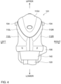
- FIG. 4 is a rear view illustrating an external configuration of the cowl 110
- FIG. 5 is a top view illustrating an external configuration of the cowl 110
- FIG. 6 is a perspective view illustrating a disassembled state of the cowl 110.
- FIG. 6 also shows the lower surface portion X1 of the rear end of the upper cover 110U, which will be described below.
- the cowl 110 includes an upper cover 110U, a left cover 110L, and a right cover 110R.
- the upper cover 110U is an example of a cover
- the left cover 110L and the right cover 110R are an example of the pair of facing covers.
- the left cover 110L and the right cover 110R are arranged to face each other through the internal structure 300 in the horizontal (left-right) direction.
- the left cover 110L covers the left side of the internal structure 300
- the right cover 110R covers the right side of the internal structure 300.
- the lower ends of each cover 110L and 110R are fixed to the internal structure 300 by a pair of lower fixing members T1, T1 (e.g., screws) (see FIG. 2 ).
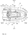
- the left cover 110L and the right cover 110R form an opening H that exposes the upper portion of the internal structure 300 (e.g., see FIG. 6 and FIG. 10 ).
- each cover 110L, 110R The shape of each cover 110L, 110R is as follows.
- the lower end of each cover 110L, 110R extends along the horizontal (front-rear) direction, and the upper end of each cover 110L, 110R slopes downward so that the distance from the lower end of each cover 110L, 110R becomes shorter as it approaches the rear end of each cover 110L, 110R (see FIG. 2 ).
- the outer surface of each cover 110L, 110R has first recessed surfaces 112L, 112R and a second recessed surface 114L (the second recessed surface on the right side is not shown) (see FIGS. 4 and 6 ).
- the first recessed surfaces 112L, 112R extend from the front end to the rear end of each cover 110L, 110R.
- the width in the upper-lower direction of the first recessed surfaces 112L, 112R narrows as it approaches the rear end of each cover 110L, 110R.
- the second recessed surface 114L is a recessed surface formed at the rear end of the first recessed surfaces 112L, 112R and deeper than the first recessed surfaces 112L, 112R.
- the front end of the second recessed surface 114L is open forward.
- a side of the clamp bracket 106 of the suspension device 102 above is provided with a third recessed surface 108 extending in the front-rear direction, and the bottom of this third recessed surface 108 is flush with the bottom of the second recessed surface 114L (see FIG. 2 and FIG. 12 below).
- the upper cover 110U is positioned to close the opening H and covers the top side of the internal structure 300 (see FIGS. 2 , 4 , and 5 ).
- the upper cover 110U has a lid-shape with a downward opening, and the width in the left-right direction of the upper cover 110U becomes narrower as it approaches the rear end of the cover 110U.
- the cowl 110 has a pair of hooks 116U and a connecting part 150.
- both the pair of hooks 116U and the connecting part 150 are disposed inside the cowl 110 so that they are not exposed to the outside.
- the connecting part 150 extends in the left-right direction and connects the left cover 110L and the right cover 110R.
- the pair of hooks 116U are formed on the upper cover 110U (see lower surface portion X1 in FIG. 6 ) and engage the connecting part 150.
- the pair of hooks 116U are formed on the lower surface 114U of the upper cover 110U.
- the pair of hooks 116U are disposed on the front portion of the upper cover 110U.
- the pair of hooks 116U are arranged to be spaced apart from each other in the left-right direction.
- Each hook 116U is formed to project downwardly from the lower surface 114U.
- Each hook 116U has a recessed hooking portion 115U that opens forward.
- Each hook 116U is flat plate-shaped in the left-right direction.
- the pair of hooks 116U are connected to each other by hook stiffeners 117U extending in the left-right direction, which suppresses deformation of each hook 116U.
- each hook 116U is thinner than the thickness D2 of the upper cover 110U (see FIG. 8 ).
- deformation due to thermal expansion of the hooks 116U can be suppressed from affecting the shape of the upper cover 110U compared to a configuration in which, for example, the thickness D1 of the hooks 116U is thicker than the thickness D2 of the upper cover 110U.
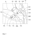
- FIG. 7 is a perspective view illustrating components of the connecting part 150
- FIG. 8 is a perspective view illustrating the engagement between the pair of hooks 116U and the connecting part 150.
- FIG. 7 shows an enlarged portion X2 of FIG. 6 .
- the connecting part 150 includes a screw receptacle 152L, a cylinder 154R, and a fixing screw T (e.g., a tapping screw).
- the fixing screw T is an example of the insert.
- the screw receptacle 152L is provided on the left cover 110L.
- the left cover 110L has a reinforcing portion 155L, and the reinforcing portion 155L extends inward (to the right) from the upper end surface 116L of the left cover 110L.
- the screw receptacle 152L is provided in this reinforcing portion 155L.
- the screw receptacle 152L has an insertion hole 154L penetrating in the left-right direction.
- the cylinder 154R is provided on the right cover 110R.
- the right cover 110R has a reinforcing portion 155R, and the reinforcing portion 155R extends inward (left side) from the upper end surface 116R of the right cover 110R.
- the cylinder 154R is provided extending from this reinforcing portion 155R in a left-right direction.
- the cylinder 154R is provided with a screw hole 156U.
- the fixing screw T is inserted through the insertion hole 154L of the screw receptacle 152L and screwed into the screw hole 156U of the cylinder 154R.
- the connecting part 150 connects the left cover 110L and the right cover 110R.
- an elastic member 160 is disposed between the connecting part 150 and each hook 116U.
- the elastic member 160 is a tubular body formed of elastic material such as rubber and is arranged to surround the cylinder 154R.
- each hook 116U engages the portion where the fixing screw T provided through the left cover 110L is inserted into the cylinder 154R provided on the right cover 110R (see FIG. 8 ). In other words, each hook 116U engages the portion where the cylinder 154R and the fixing screw T overlap. This allows the load from the hooks 116U to be distributed between the left cover 110L and the right cover 110R.
- the left cover 110L and the right cover 110R each have contact portions 153L and 153R, respectively, that contact each hook 116U in the left-right direction.
- the contact portion 153L is the inner surface of the screw receptacle 152L and contacts the left side of the left hook 116U.
- the contact portion 153R is formed on the reinforcing portion 155R and has an inner side facing the inner side of the screw receptacle 152L in the left-right direction; the cylinder 154R is formed on this inner side, and the surrounding surface of the cylinder 154R is the contact portion 153R.
- the contact portion 153R contacts the right side of the right hook 116U.
- the pair of hooks 116U are sandwiched between the contact portions 153L and 153R in the left-right direction, thereby restricting the left-right movement of the pair of hooks 116U.
- the elastic member 160 is also sandwiched between the contact portions 153L and 153R in the left-right direction, thereby restricting the left-right movement of the elastic member 160.
- FIG. 9 is an explanatory view illustrating the pivot of the upper cover 11 0U.
- the upper cover 110U is configured to pivot about the connecting part 150 (fixing screw T) and is displaceable into a closed position and an opened position.
- the closed position is the position that covers the opening H formed by the left cover 110L and the right cover 110R (see the upper view in FIG. 9 ).
- the opened position is the position that opens at least part of the opening H (see the lower view in FIG. 9 ).
- the upper cover 110U covers the entire opening H, and the front end 111 of the upper cover 110U contacts the wiring support 310 described below.
- the rear end 113 of the upper cover 110U is separated in the upper-lower direction from both the upper end surface 116L of the left cover 110L and the upper end surface 116R of the right cover 11 0R.
- a gap U is formed in the upper-lower direction between the rear end 113 of the upper cover 110U and the upper end surfaces 116L, 116R.
- the lower surface 112U of the periphery of the upper cover 110U is spaced apart from the upper end surfaces 116L, 116R in the upper-lower direction over the entire circumference. This can suppress displacement or deformation of the upper cover 110U due to displacement or deformation of the left cover 110L and the right cover 110R (see FIG. 2 ).
- each cover 110L, 110R In the upper end surfaces 116L, 116R of each cover 110L, 110R, recesses 180L, 180R are formed (see FIGS. 6 and 9 ). Each recess 180L, 180R is open upwardly.
- the upper cover 110U is provided with a pair of protrusions 182. Each protrusion 182 protrudes downwardly. The pair of protrusions 182 are inserted into the recesses 180L, 180R when the upper cover 110U is in the closed position (see the upper figure in FIG. 9 ) and are released from the recesses 180L, 180R when the upper cover 110U is in the opened position (see the lower figure in FIG. 9 ).
- the other pair of the first fixing members T2 are inserted into the front portions of the left cover 110L and the right cover 110R in the upper-lower direction and fixed to the internal structure 300.
- the upper cover 110U covers all four of the first fixing members T2 (see FIGS. 4 and 5 ).
- the first fixing members T2 are male screws, but they may be engagement claws or press-fit protrusions.
- the electric propulsion device 100 is further provided with a wiring support 310 and a hang tab 320.
- the wiring support 310 is a tubular member for bundling wires 314 connected to the internal structure 300 and guiding them to the hull 10 side.
- the wiring support 310 is disposed in the front side of the opening H so that it protrudes upwardly from the opening H (see FIG. 11 ).
- the wiring support 310 is fixed to the internal structure 300 via a fixing jig 312. When the upper cover 110U is in the closed position, only a part (rear end) of the wiring support 310 is covered by the upper cover 110U (see FIGS. 2 and 5 ).
- the hang tab 320 is a member with a through hole 322 through which a hook of a crane truck (not shown) or the like can be hooked.
- the hang tab 320 is positioned in the internal structure 300 at a position exposed to the opening H.
- the hanging portion (through hole 322) of the hang tab 320 protrudes upwardly from the opening H (see FIG. 11 ).
- the entire hang tab 320 is covered by the upper cover 110U (see FIGS. 2 and 5 ).
- the cowl 110 further includes a pair of second fixing members T3 for fixing the front portion of the upper cover 110U to the internal structure 300.
- the front portion of the upper cover 110U is positioned to cover the fixing jig 312 from the front.
- a pair of the second fixing members T3 are inserted into the front portion of the upper cover 110U in the front-rear direction and fixed to the fixing jig 312.
- the second fixing members T3 are male screws, but they may be an engagement claw or a press-fit projection.
- the connecting part 150 extends in the left-right direction and connects the left cover 110L and the right cover 110R.
- a pair of hooks 116U are formed on the upper cover 110U (see lower surface portion X1 in FIG. 6 ) and engage the connecting part 150 (see FIGS. 6 and 8 ).
- the hook 116U of the upper cover 110U engages the connecting part 150 that connects the left cover 110L and the right cover 110R, so that the left cover 110L, the right cover 110R, and the upper cover 110U can be aligned and positioned with high precision.
- both the pair of hooks 116U and the connecting part 150 are arranged inside the cowl 110 so that they are not exposed to the outside. This improves the design of the appearance of the electric propulsion device 100.
- the upper cover 110U is configured to pivot about the connecting part 150 (fixing screw T) to be displaced between the closed and opened positions (see FIG. 9 ). This allows the upper cover 110U to be easily displaced between the closed and opened positions by pivoting about the connecting part 150, while maintaining the positional relationship of the three covers 110U, 110L, and 110R. In addition, only the upper cover 110U can be removed to perform work (e.g., maintenance work) on the internal structure 300.
- the pair of protrusions 182 are inserted into the recesses 180L, 180R when the upper cover 110U is in the closed position and are released from the recesses 180L, 180R when the upper cover 110U is in the opened position (see FIG. 9 ).
- This allows the three covers 110U, 110L, and 110R to be more precisely aligned and positioned when the upper cover 110U is in the closed position, as the protrusion 182 is inserted into the recesses 180L, 180R.
- the elastic member 160 is disposed between the connecting part 150 and each hook 116U (see FIGS. 7 and 8 ). This can suppress the rattling of the upper cover 110U against the left cover 110L and the right cover 110R and absorb vibration.
- the hang tab 320 is provided at the position of the internal structure 300 that is exposed to the opening H. Only the upper cover 110U can be removed and the hang tab 320 can be used to lift up the electric propulsion device 100.
- the hanging portion (through hole 322) of the hang tab 320 protrudes upwardly from the opening H (see FIG. 11 ). This allows the electric propulsion device 100 in, e.g., a side-lying position to be lifted up by using the hang tab 320.
- the cowl 110 further includes a pair of second fixing members T3 for fixing the front portion of the upper cover 110U to the internal structure 300. This allows the left cover 110L, the right cover 110R, and the upper cover 110U to be precisely aligned and positioned, while suppressing the influence of the second fixing members T3 on the appearance design of the electric propulsion device 100 when the electric propulsion device 100 is viewed from the rear.
- the configuration of the boat 1 in the above embodiment is only an example and can be modified in various ways.
- the electric propulsion device 100 is shown as an example of the boat propulsion device, but an outboard motor, an inboard/outboard motor, or a jet propulsion system can also be used, for example.
- the drive source for these outboard motors may be an electric motor or an internal combustion engine.
- the internal structure 300 provided with a motor control unit that controls the electric motor 134 and gear mechanism is illustrated as an internal structure, but an internal structure provided with an engine control unit or other drive source (such as an internal combustion engine) may also be used.
- the cowl 110 may have one or more than three hooks 116U.
- the upper cover with multiple hooks will be able to stabilize the position of the upper cover relative to a pair of facing covers more effectively than the upper cover with only one hook.
- At least one of the hooks 116U and the connecting part 150 may be arranged to be exposed to the outside.
- the hook 116U is configured to rotatably engage the cylindrical connecting part 150 to allow the upper cover 110U to pivot.
- the hook may be configured to slide in a predetermined direction (e.g., forward direction) against the connecting part for engagement to allow the upper cover 110U to slide and move.
- the connecting part 150 has a threaded structure in which the fixing screw T is screwed into the cylinder 154R.
- the connecting part 150 may have a press-fit structure in which an insert is press-fitted into the cylinder.
- the connecting part 150 may not have the elastic member 160.
- the protrusions 182 may be provided on each cover 110L, 110R, and the recesses 180L, 180R may be formed on the upper cover 110U.
- the pair of facing covers is exemplified as the left cover 110L and the right cover 110R facing in the left-right direction.
- they may be a pair of facing covers facing in other directions, such as the upper-lower direction or the front-rear direction, for example.
Landscapes
- Chemical & Material Sciences (AREA)
- Engineering & Computer Science (AREA)
- Combustion & Propulsion (AREA)
- Mechanical Engineering (AREA)
- Ocean & Marine Engineering (AREA)
- Motor Or Generator Frames (AREA)
- Connector Housings Or Holding Contact Members (AREA)
Abstract
Description
- The present invention disclosed herein relates to a boat propulsion device and a boat.
- Conventionally, outboard motors are known in which an internal structure such as an engine is covered by a plurality of covers (see, e.g.
JP 2022-104230 A JP 2019-10992 A JP 2019-10993 A - In conventional outboard motors, it is sometimes impossible to precisely align and position a pair of facing covers and an upper cover, e.g., because the positional relationship of one facing cover to the upper cover differs from that of the other. This problem is not limited to outboard motors but is also common to other boat propulsion devices, such as inboard and outboard motors.
- It is the object of the present invention to provide a boat propulsion device and a boat having proper positional relationship of the covers.
- According to the present invention said object is solved by a boat propulsion device having the features of
independent claim 1. Moreover, said object is also solved by a boat according toclaim 15. Preferred embodiments are laid down in the dependent claims. - The technology disclosed herein can be implemented as the following aspects.
- A boat propulsion device disclosed herein includes: an internal structure; a pair of facing covers arranged to face each other through the internal structure in a first direction along a horizontal direction to form an opening to expose an upper portion of the internal structure; a connecting part extending in the first direction and connecting the pair of facing covers together; and an upper cover covering the opening and having a hook that engages the connecting part. According to this boat propulsion device, the hook of the upper cover engages the connecting part that connects the pair of facing covers, so that the pair of facing covers and the upper cover can be aligned and positioned with high precision.
- The above boat propulsion device may be configured such that the connecting part is provided on the respective facing walls of the pair of facing covers, the hook is provided on the lower surface of the upper cover, and the engaged portion between the connecting part and the hook are covered by the pair of facing covers and the upper cover. According to this boat propulsion device, the engaged portion between the connecting part and the hook is not exposed to the outside, which improves the design of the appearance of the boat propulsion device.
- The above boat propulsion device may be configured such that the upper cover is configured to pivot about the connecting part, displaceable between a closed position that covers the opening and an opened position that opens at least a portion of the opening, and detachable from the pair of facing covers. According to this boat propulsion device, the upper cover can be easily displaced to the closed position and to the opened position by pivoting about the connecting part, while maintaining the positional relationship of the three covers. In addition, according to this boat propulsion device, only the upper cover can be removed to perform work (such as maintenance) on the internal structure.
- The above boat propulsion device may be configured such that one of the upper cover and the facing cover is provided with a recess formed thereon, and the other of the upper cover and the facing cover is provided with a protrusion which is inserted into the recess when the upper cover is in the closed position and is released from the recess when the upper cover is in the opened position. According to this boat propulsion device, when the upper cover is in the closed position, the protrusion is inserted into the recess, thereby enabling the three covers to be aligned and positioned with greater precision.
- The above boat propulsion device may be configured such that an elastic member is disposed between the connecting part and the hook. According to this boat propulsion device, the rattling of the upper cover against the facing covers can be suppressed, and vibration can be absorbed.
- The above boat propulsion device may be configured such that the internal structure includes at least one of a control unit and a drive source, the boat propulsion device further includes a first fixing member that fixes the pair of facing covers to the internal structure, and the upper cover covers the first fixing member. According to this boat propulsion device, the upper cover can be positioned with respect to the facing covers through the internal structure. Also, according to this boat propulsion device, the first fixing member is not exposed to the outside, which improves the design of the appearance of the boat propulsion device.
- The above boat propulsion device may be configured such that the upper cover has a lower edge that is spaced apart from the pair of facing covers. According to this boat propulsion device, it is possible to suppress the direct influence of deformation of the upper cover on the facing covers.
- The above boat propulsion device may be configured such that the internal structure is provided with a hang tab at a position that is exposed to the opening. According to this boat propulsion device, the hang tab can be used to lift up the boat propulsion device by removing only the upper cover.
- The above boat propulsion device may be configured such that the hang tab has a hanging portion that protrudes upwardly from the opening. According to this boat propulsion device, e.g., a boat propulsion device in a lying down state can be lifted up using the hang tab.
- The above boat propulsion device may be configured such that each of the facing covers has a contact portion that contacts the hook in the first direction. According to this boat propulsion device, misalignment of the upper cover with respect to the pair of facing covers in the first direction can be suppressed.
- The above boat propulsion device may be configured such that the connecting part is located at the rear end side of the upper cover, and the boat propulsion device further includes a second fixing member that fixes the front end side of the upper cover to the internal structure. In this boat propulsion device, the rear end side of the upper cover is positioned with respect to the facing covers by the hook while the front end side of the upper cover is fixed by the second fixing member. As a result, according to this boat propulsion device, the pair of facing covers and the upper cover can be precisely aligned and positioned, while the second fixing member can be suppressed from affecting the design of the appearance of the boat propulsion device when the boat propulsion device is viewed from the rear.
- The above boat propulsion device may be configured such that the connecting part includes a cylinder provided on one of the two facing covers and an insert provided on the other of the two facing covers that is inserted into the cylinder. According to this boat propulsion device, misalignment between the pair of facing covers can be effectively suppressed.
- The above boat propulsion device may be configured such that the hook engages a portion of the connecting part where the insert is inserted into the cylinder. According to this boat propulsion device, the load from the hook can be distributed by the pair of facing covers.
- A boat propulsion device disclosed herein includes: an internal structure; a pair of facing covers arranged to face each other through the internal structure in a first direction to form an opening to expose one side of the internal structure in a second direction perpendicular to the first direction; a connecting part extending in the first direction and connecting the pair of facing covers together; and a cover covering the opening and having a hook that engage the connecting part. According to this boat propulsion device, the hook of the cover engages the connecting part that connects the pair of facing covers, so that the pair of facing covers and the cover can be aligned and positioned with high precision.
- The technology disclosed herein can be implemented in various forms, e.g., in the form of an outboard motor, a boat propulsion device, a boat equipped with a boat propulsion device, and a method for aligning a plurality of covers.
- According to the boat propulsion device disclosed herein, a pair of facing covers and a cover can be aligned and positioned with high accuracy.
-
-
FIG. 1 is a perspective view schematically illustrating a configuration of an embodiment of a boat. -
FIG. 2 is a side view schematically illustrating a configuration of an electric propulsion device. -
FIG. 3 is a schematic view illustrating a configuration of a drive unit. -
FIG. 4 is a rear view illustrating an external configuration of a cowl. -
FIG. 5 is a top view illustrating an external configuration of the cowl. -
FIG. 6 is a perspective view illustrating a disassembled state of the cowl. -
FIG. 7 is a perspective view illustrating components of a connecting part. -
FIG. 8 is a perspective view illustrating the engagement between the hook and the connecting part. -
FIG. 9 is an explanatory view illustrating the pivot of the upper cover. -
FIG. 10 is a top view illustrating the electric propulsion device with the upper cover removed. -
FIG. 11 is a side view illustrating the electric propulsion device with the upper cover removed. -
FIG. 12 is a perspective view illustrating the electric propulsion device with the upper cover removed. -
FIG. 1 is a perspective view schematically illustrating the configuration of aboat 1 in this embodiment.FIG. 1 and other drawings described below show arrows representing each direction with respect to the position of theboat 1. More specifically, each figure shows arrows representing front (FRONT), rear (REAR), left (LEFT), right (RIGHT), upper (UPPER), and lower (LOWER) directions, respectively. The front-rear direction, left-right direction, and upper-lower direction (vertical direction) are orthogonal to each other. As shown inFIG. 1 , theboat 1 is equipped with ahull 10 and anelectric propulsion device 100. Theelectric propulsion device 100 is an example of the boat propulsion device. - The
hull 10 is a part of theboat 1 for occupants to ride. As shown inFIG. 1 , thehull 10 has ahull body 12 having a livingspace 11, apilot seat 16 installed in the livingspace 11, and an operatingdevice 17 installed near thepilot seat 16. The operatingdevice 17 is a device for maneuvering the boat and includes, e.g., a steering wheel, a shift throttle lever, a joystick, a monitor, and an input device. Thehull 10 also has apartition wall 13 that partitions the rear end of the livingspace 11 and a transom 14 positioned at the rear end of thehull 10. In the front-rear direction, aspace 15 exists between the transom 14 and thepartition wall 13. -
FIG. 2 is a side view schematically illustrating a configuration of anelectric propulsion device 100. Theelectric propulsion device 100 is a device that generates thrust to propel theboat 1. Theelectric propulsion device 100 is an electric propulsion device driven by an electric motor (an example of the drive source). In the following, theelectric propulsion device 100 in the reference attitude will be described unless otherwise specified. The reference attitude is the attitude of theelectric propulsion device 100 when theboat 1 is running (attitude shown inFIG. 1 ) and is the attitude in which the propeller rotation axis L of the propeller 132 (described below) extends in the front-rear direction. The front-rear direction, the left-right direction, and the upper-lower direction are defined on the basis of theelectric propulsion device 100 in the reference attitude. - The
electric propulsion device 100 is attached to atransom 14 disposed at the rear (stern) of the hull 10 (seeFIG. 1 ). As shown inFIG. 2 , theelectric propulsion device 100 has a propulsion devicemain body 101 and asuspension device 102. - The
suspension device 102 is a device for suspending the propulsion devicemain body 101 to thehull 10. Thesuspension device 102 includes atilt shaft 104, a pair of left andright clamp brackets 106, and a connection bracket 109 (seeFIG. 5 below). - The pair of left and
right clamp brackets 106 are disposed behind thehull 10 in a state separated from each other in the left-right direction and fixed to thetransom 14 of thehull 10 by using, e.g., bolts. Eachclamp bracket 106 has a cylindrical supportingportion 106a with a through-hole extending in the left-right direction. - The
tilt shaft 104 is a rod-shaped member. Thetilt shaft 104 is rotatably supported in the through-hole of the supportingportion 106a of theclamp bracket 106. The tilt axis At, which is the center line of thetilt shaft 104, constitutes an axis in the horizontal direction (left-right direction) in the tilting action of theelectric propulsion device 100. - The
connection bracket 109 is disposed so as to be sandwiched between the pair ofclamp brackets 106 in the left-right direction and is supported by the supportingportion 106a of theclamp brackets 106 via thetilt shaft 104 in such a manner that theconnection bracket 109 can rotate about the tilt axis At. Theconnection bracket 109 is fixed to the base of the propulsion device main body 101 (not shown). Theconnection bracket 109 is driven to pivot about the tilt axis At with respect to theclamp bracket 106 by a tilt device (not shown) including an actuator such as a hydraulic cylinder. - When the
connection bracket 109 rotates about the tilt axis At with respect to theclamp bracket 106, the propulsion devicemain body 101 fixed to theconnection bracket 109 also rotates about the tilt axis At. This achieves the tilting action of rotating the propulsion devicemain body 101 in the upper-lower direction with respect to thehull 10. By this tilting cation, theelectric propulsion device 100 can change the angle about the tilt axis At of the propulsion devicemain body 101 in the range from the tilt-down state in which thepropeller 132 is in the water (the state in which theelectric propulsion device 100 is in the reference attitude: the state shown inFIG. 2 ) to tilt-up state in which thepropeller 132 is located above the waterline. Trimming action for adjusting the attitude of theboat 1 during travel can also be performed by adjusting the angle around the tilt axis At of the propulsion devicemain body 101. - The propulsion device
main body 101 includes acowl 110, amiddle housing 140, alower housing 120, aduct 122, and adrive unit 130. - An internal structure 300 (e.g., see
FIG. 10 below) is disposed on a base fixed to theconnection bracket 109 of thesuspension device 102. Theinternal structure 300 is a structure located at the upper portion of the electric propulsion device 100 (propulsion device main body 101), in other words, a structure of a portion exposed to the outside when theupper cover 110U described below is removed. In this embodiment, theinternal structure 300 includes a motor control unit (MCU) that controls theelectric motor 134 and gear mechanism described below. Thecowl 110 covers theinternal structure 300. The detailed configuration of thecowl 110 is described below. - The
middle housing 140 is fixed to the underside of the base, and thelower housing 120 is disposed belowmiddle housing 140. Thelower housing 120 extends downward frommiddle housing 140. Theduct 122 is disposed below thelower housing 120. Theduct 122 is tubular in shape. Theduct 122 is disposed below the water surface W (seeFIG. 2 ). Thedrive unit 130 is disposed in theduct 122. -
FIG. 3 is a schematic view illustrating a configuration of thedrive unit 130. Thedrive unit 130 generates thrust to propel theboat 1. As shown inFIG. 3 , thedrive unit 130 includes apropeller 132 and anelectric motor 134. Theelectric motor 134 is an example of the drive source. - The
propeller 132 is a rotating body having a plurality of wings and generates thrust by rotating. Thepropeller 132 is located at the inner side of theduct 122 and is rotatable about a horizontal propeller rotation axis L. The propeller rotation axis L is parallel to the central axis of theduct 122. Theduct 122 covers the entire circumference of thepropeller 132, and the duct effect of theduct 122 increases the velocity of water flowing into theduct 122. - A
stator fin 133 and abearing 135 are provided radially inward of theduct 122. Thebearing 135 supports thepropeller 132 rotatably about the propeller rotation axis L. Thestator fin 133 has a plurality of fins (e.g., three fins). The plurality of fins are arranged radially around thebearing 135, equally spaced around the propeller rotation axis L, and fixed to theduct 122. The plurality of fins are provided behind thepropeller 132 so that they protrude rearwardly from the duct 122 (seeFIGS. 1 and2 ). - The
electric motor 134 rotatespropeller 132. Theelectric motor 134 includes arotor 136 and astator 138. Therotor 136 andstator 138 each have a tubular shape. Therotor 136 is disposed radially inward of thestator 138. In addition, therotor 136 and thestator 138 are arranged on the same axis. Therotor 136 is rotatably supported against theduct 122. Therotor 136 rotates about the propeller rotation axis L with respect to thestator 138. Thepropeller 132 is disposed radially inward of therotor 136. Thepropeller 132 is fixed to therotor 136 and rotates along with therotor 136. Therotor 136 includes a plurality ofpermanent magnets 140. The plurality ofpermanent magnets 140 are arranged along the circumferential direction of therotor 136. InFIG. 3 , only one of the plurality ofpermanent magnets 140 is labeled with asign 140, and the signs of the otherpermanent magnets 140 are omitted. - The
stator 138 is fixed to theduct 122. Thestator 138 includes a plurality ofcoils 142. The plurality ofcoils 142 are arranged along the circumferential direction of thestator 138. When the plurality ofcoils 142 are energized, an electromagnetic force is generated to rotate therotor 136. InFIG. 3 , only one of the plurality ofcoils 142 is labeled with asign 142, and the signs of theother coils 142 are omitted. With the above configuration, thepropeller 132 generates forward propulsive force when theelectric motor 134 rotates in normal rotation direction and rearward propulsive force when theelectric motor 134 rotates in reverse rotation direction. - In the
electric propulsion device 100, thelower housing 120 is pivotably attached to themiddle housing 140 around a steering axis (an axis along the upper-lower direction in each figure) as a vertical pivot axis. Themiddle housing 140 accommodates a gear mechanism (not shown) for allowing thelower housing 120 to pivot. As thelower housing 120 pivots, thedrive unit 130 also pivots about the steering axis. -
FIG. 4 is a rear view illustrating an external configuration of thecowl 110,FIG. 5 is a top view illustrating an external configuration of thecowl 110, andFIG. 6 is a perspective view illustrating a disassembled state of thecowl 110.FIG. 6 also shows the lower surface portion X1 of the rear end of theupper cover 110U, which will be described below. As shown inFIGS. 4 to 6 , thecowl 110 includes anupper cover 110U, aleft cover 110L, and aright cover 110R. Theupper cover 110U is an example of a cover, and theleft cover 110L and theright cover 110R are an example of the pair of facing covers. - The
left cover 110L and theright cover 110R are arranged to face each other through theinternal structure 300 in the horizontal (left-right) direction. Theleft cover 110L covers the left side of theinternal structure 300, and theright cover 110R covers the right side of theinternal structure 300. The lower ends of eachcover internal structure 300 by a pair of lower fixing members T1, T1 (e.g., screws) (seeFIG. 2 ). Theleft cover 110L and theright cover 110R form an opening H that exposes the upper portion of the internal structure 300 (e.g., seeFIG. 6 andFIG. 10 ). - The shape of each
cover cover cover cover cover FIG. 2 ). The outer surface of eachcover surfaces surface 114L (the second recessed surface on the right side is not shown) (seeFIGS. 4 and6 ). The first recessedsurfaces cover surfaces cover surface 114L is a recessed surface formed at the rear end of the first recessedsurfaces surfaces surface 114L is open forward. A side of theclamp bracket 106 of thesuspension device 102 above is provided with a third recessedsurface 108 extending in the front-rear direction, and the bottom of this third recessedsurface 108 is flush with the bottom of the second recessedsurface 114L (seeFIG. 2 andFIG. 12 below). - The
upper cover 110U is positioned to close the opening H and covers the top side of the internal structure 300 (seeFIGS. 2 ,4 , and5 ). Theupper cover 110U has a lid-shape with a downward opening, and the width in the left-right direction of theupper cover 110U becomes narrower as it approaches the rear end of thecover 110U. - The
cowl 110 has a pair ofhooks 116U and a connectingpart 150. In this configuration, both the pair ofhooks 116U and the connectingpart 150 are disposed inside thecowl 110 so that they are not exposed to the outside. The connectingpart 150 extends in the left-right direction and connects theleft cover 110L and theright cover 110R. The pair ofhooks 116U are formed on theupper cover 110U (see lower surface portion X1 inFIG. 6 ) and engage the connectingpart 150. - Specifically, the pair of
hooks 116U are formed on thelower surface 114U of theupper cover 110U. In addition, the pair ofhooks 116U are disposed on the front portion of theupper cover 110U. The pair ofhooks 116U are arranged to be spaced apart from each other in the left-right direction. Eachhook 116U is formed to project downwardly from thelower surface 114U. Eachhook 116U has a recessed hookingportion 115U that opens forward. Eachhook 116U is flat plate-shaped in the left-right direction. The pair ofhooks 116U are connected to each other byhook stiffeners 117U extending in the left-right direction, which suppresses deformation of eachhook 116U. The thickness D1 of eachhook 116U is thinner than the thickness D2 of theupper cover 110U (seeFIG. 8 ). Thus, deformation due to thermal expansion of thehooks 116U can be suppressed from affecting the shape of theupper cover 110U compared to a configuration in which, for example, the thickness D1 of thehooks 116U is thicker than the thickness D2 of theupper cover 110U. -
FIG. 7 is a perspective view illustrating components of the connectingpart 150, andFIG. 8 is a perspective view illustrating the engagement between the pair ofhooks 116U and the connectingpart 150.FIG. 7 shows an enlarged portion X2 ofFIG. 6 . As shown inFIG. 7 , the connectingpart 150 includes ascrew receptacle 152L, acylinder 154R, and a fixing screw T (e.g., a tapping screw). The fixing screw T is an example of the insert. - The
screw receptacle 152L is provided on theleft cover 110L. Specifically, theleft cover 110L has a reinforcingportion 155L, and the reinforcingportion 155L extends inward (to the right) from theupper end surface 116L of theleft cover 110L. Thescrew receptacle 152L is provided in this reinforcingportion 155L. Thescrew receptacle 152L has aninsertion hole 154L penetrating in the left-right direction. Thecylinder 154R is provided on theright cover 110R. Specifically, theright cover 110R has a reinforcingportion 155R, and the reinforcingportion 155R extends inward (left side) from theupper end surface 116R of theright cover 110R. Thecylinder 154R is provided extending from this reinforcingportion 155R in a left-right direction. Thecylinder 154R is provided with a screw hole 156U. - The fixing screw T is inserted through the
insertion hole 154L of thescrew receptacle 152L and screwed into the screw hole 156U of thecylinder 154R. As a result, the connectingpart 150 connects theleft cover 110L and theright cover 110R. In this embodiment, anelastic member 160 is disposed between the connectingpart 150 and eachhook 116U. Specifically, theelastic member 160 is a tubular body formed of elastic material such as rubber and is arranged to surround thecylinder 154R. - In the connecting
part 150, eachhook 116U engages the portion where the fixing screw T provided through theleft cover 110L is inserted into thecylinder 154R provided on theright cover 110R (seeFIG. 8 ). In other words, eachhook 116U engages the portion where thecylinder 154R and the fixing screw T overlap. This allows the load from thehooks 116U to be distributed between theleft cover 110L and theright cover 110R. - The
left cover 110L and theright cover 110R each havecontact portions hook 116U in the left-right direction. Specifically, thecontact portion 153L is the inner surface of thescrew receptacle 152L and contacts the left side of theleft hook 116U. Thecontact portion 153R is formed on the reinforcingportion 155R and has an inner side facing the inner side of thescrew receptacle 152L in the left-right direction; thecylinder 154R is formed on this inner side, and the surrounding surface of thecylinder 154R is thecontact portion 153R. Thecontact portion 153R contacts the right side of theright hook 116U. In other words, the pair ofhooks 116U are sandwiched between thecontact portions hooks 116U. Theelastic member 160 is also sandwiched between thecontact portions elastic member 160. -
FIG. 9 is an explanatory view illustrating the pivot of theupper cover 11 0U. Theupper cover 110U is configured to pivot about the connecting part 150 (fixing screw T) and is displaceable into a closed position and an opened position. The closed position is the position that covers the opening H formed by theleft cover 110L and theright cover 110R (see the upper view inFIG. 9 ). The opened position is the position that opens at least part of the opening H (see the lower view inFIG. 9 ). When theupper cover 110U is in the closed position, theupper cover 110U covers the entire opening H, and thefront end 111 of theupper cover 110U contacts thewiring support 310 described below. - The
rear end 113 of theupper cover 110U is separated in the upper-lower direction from both theupper end surface 116L of theleft cover 110L and theupper end surface 116R of theright cover 11 0R. Thus, a gap U is formed in the upper-lower direction between therear end 113 of theupper cover 110U and the upper end surfaces 116L, 116R. In this embodiment, thelower surface 112U of the periphery of theupper cover 110U is spaced apart from the upper end surfaces 116L, 116R in the upper-lower direction over the entire circumference. This can suppress displacement or deformation of theupper cover 110U due to displacement or deformation of theleft cover 110L and theright cover 110R (seeFIG. 2 ). - On the other hand, as shown in the lower figure of
FIG. 9 , when theupper cover 110U is in the opened position, theupper cover 110U pivots about the connectingpart 150, and thefront end 111 of theupper cover 110U is separated from thewiring support 310. In this action, the presence of the gap U allows theupper cover 110U to pivot while suppressing interference with therespective covers upper cover 110U is moved from the closed position to the opened position and therear end 113 of theupper cover 110U is displaced rearwardly, the pair ofhooks 116U can be removed from theleft cover 110L and theright cover 110R by disengaging thehooks 116U and the connectingpart 150. - In the upper end surfaces 116L, 116R of each
cover FIGS. 6 and9 ). Eachrecess upper cover 110U is provided with a pair ofprotrusions 182. Eachprotrusion 182 protrudes downwardly. The pair ofprotrusions 182 are inserted into therecesses upper cover 110U is in the closed position (see the upper figure inFIG. 9 ) and are released from therecesses upper cover 110U is in the opened position (see the lower figure inFIG. 9 ). -
FIG. 10 is a top view illustrating theelectric propulsion device 100 with theupper cover 110U removed,FIG. 11 is a side view illustrating theelectric propulsion device 100 with theupper cover 110U removed, andFIG. 12 is a perspective view illustrating theelectric propulsion device 100 with theupper cover 110U removed. As shown inFIGS. 10 and12 , thecowl 110 has four first fixing members T2 for fixing theleft cover 110L and theright cover 110R to theinternal structure 300. One pair of the first fixing members T2 are inserted into the rear portions of theleft cover 110L and theright cover 110R in the left-right direction and fixed to theinternal structure 300. The other pair of the first fixing members T2 are inserted into the front portions of theleft cover 110L and theright cover 110R in the upper-lower direction and fixed to theinternal structure 300. When theupper cover 110U is in the closed position, theupper cover 110U covers all four of the first fixing members T2 (seeFIGS. 4 and5 ). Here, the first fixing members T2 are male screws, but they may be engagement claws or press-fit protrusions. - The
electric propulsion device 100 is further provided with awiring support 310 and ahang tab 320. Thewiring support 310 is a tubular member for bundlingwires 314 connected to theinternal structure 300 and guiding them to thehull 10 side. Thewiring support 310 is disposed in the front side of the opening H so that it protrudes upwardly from the opening H (seeFIG. 11 ). Thewiring support 310 is fixed to theinternal structure 300 via a fixingjig 312. When theupper cover 110U is in the closed position, only a part (rear end) of thewiring support 310 is covered by theupper cover 110U (seeFIGS. 2 and5 ). - The
hang tab 320 is a member with a throughhole 322 through which a hook of a crane truck (not shown) or the like can be hooked. Thehang tab 320 is positioned in theinternal structure 300 at a position exposed to the opening H. The hanging portion (through hole 322) of thehang tab 320 protrudes upwardly from the opening H (seeFIG. 11 ). When theupper cover 110U is in the closed position, theentire hang tab 320 is covered by theupper cover 110U (seeFIGS. 2 and5 ). - The
cowl 110 further includes a pair of second fixing members T3 for fixing the front portion of theupper cover 110U to theinternal structure 300. When theupper cover 110U is in the closed position, the front portion of theupper cover 110U is positioned to cover the fixingjig 312 from the front. A pair of the second fixing members T3 are inserted into the front portion of theupper cover 110U in the front-rear direction and fixed to the fixingjig 312. Here, the second fixing members T3 are male screws, but they may be an engagement claw or a press-fit projection. - In this embodiment of the
electric propulsion device 100, the connectingpart 150 extends in the left-right direction and connects theleft cover 110L and theright cover 110R. A pair ofhooks 116U are formed on theupper cover 110U (see lower surface portion X1 inFIG. 6 ) and engage the connecting part 150 (seeFIGS. 6 and8 ). Thus, according to this embodiment, thehook 116U of theupper cover 110U engages the connectingpart 150 that connects theleft cover 110L and theright cover 110R, so that theleft cover 110L, theright cover 110R, and theupper cover 110U can be aligned and positioned with high precision. - In this embodiment, both the pair of
hooks 116U and the connectingpart 150 are arranged inside thecowl 110 so that they are not exposed to the outside. This improves the design of the appearance of theelectric propulsion device 100. Theupper cover 110U is configured to pivot about the connecting part 150 (fixing screw T) to be displaced between the closed and opened positions (seeFIG. 9 ). This allows theupper cover 110U to be easily displaced between the closed and opened positions by pivoting about the connectingpart 150, while maintaining the positional relationship of the threecovers upper cover 110U can be removed to perform work (e.g., maintenance work) on theinternal structure 300. - In this embodiment, the pair of
protrusions 182 are inserted into therecesses upper cover 110U is in the closed position and are released from therecesses upper cover 110U is in the opened position (seeFIG. 9 ). This allows the threecovers upper cover 110U is in the closed position, as theprotrusion 182 is inserted into therecesses - In this embodiment, the
elastic member 160 is disposed between the connectingpart 150 and eachhook 116U (seeFIGS. 7 and8 ). This can suppress the rattling of theupper cover 110U against theleft cover 110L and theright cover 110R and absorb vibration. - ln this embodiment, the
hang tab 320 is provided at the position of theinternal structure 300 that is exposed to the opening H. Only theupper cover 110U can be removed and thehang tab 320 can be used to lift up theelectric propulsion device 100. The hanging portion (through hole 322) of thehang tab 320 protrudes upwardly from the opening H (seeFIG. 11 ). This allows theelectric propulsion device 100 in, e.g., a side-lying position to be lifted up by using thehang tab 320. - ln this embodiment, the
cowl 110 further includes a pair of second fixing members T3 for fixing the front portion of theupper cover 110U to theinternal structure 300. This allows theleft cover 110L, theright cover 110R, and theupper cover 110U to be precisely aligned and positioned, while suppressing the influence of the second fixing members T3 on the appearance design of theelectric propulsion device 100 when theelectric propulsion device 100 is viewed from the rear. - The technology disclosed herein is explained with regard to the embodiments described above. Said embodiments can be modified into various forms to the extent not departing from the present teaching, for example, the following modifications are possible.
- The configuration of the
boat 1 in the above embodiment is only an example and can be modified in various ways. For example, in the above embodiment, theelectric propulsion device 100 is shown as an example of the boat propulsion device, but an outboard motor, an inboard/outboard motor, or a jet propulsion system can also be used, for example. The drive source for these outboard motors may be an electric motor or an internal combustion engine. In the above embodiment, theinternal structure 300 provided with a motor control unit that controls theelectric motor 134 and gear mechanism is illustrated as an internal structure, but an internal structure provided with an engine control unit or other drive source (such as an internal combustion engine) may also be used. - In the above embodiment, the
cowl 110 may have one or more than threehooks 116U. However, the upper cover with multiple hooks will be able to stabilize the position of the upper cover relative to a pair of facing covers more effectively than the upper cover with only one hook. - In the above embodiment, at least one of the
hooks 116U and the connectingpart 150 may be arranged to be exposed to the outside. In the above embodiment, thehook 116U is configured to rotatably engage the cylindrical connectingpart 150 to allow theupper cover 110U to pivot. Alternatively, the hook may be configured to slide in a predetermined direction (e.g., forward direction) against the connecting part for engagement to allow theupper cover 110U to slide and move. - In the above embodiment, the connecting
part 150 has a threaded structure in which the fixing screw T is screwed into thecylinder 154R. Alternatively, the connectingpart 150 may have a press-fit structure in which an insert is press-fitted into the cylinder. The connectingpart 150 may not have theelastic member 160. In the above embodiment, theprotrusions 182 may be provided on eachcover recesses upper cover 110U. - In the above embodiment, the pair of facing covers is exemplified as the
left cover 110L and theright cover 110R facing in the left-right direction. Alternatively, they may be a pair of facing covers facing in other directions, such as the upper-lower direction or the front-rear direction, for example.
Claims (15)
- A boat propulsion device (100) for a boat (1), boat propulsion device (100) comprising:an internal structure (300);a pair of facing covers (110L, 110R) arranged to face each other through the internal structure (300) in a first direction to form an opening (H) to expose one side of the internal structure (300) in a second direction perpendicular to the first direction;a connecting part (150) extending in the first direction and connecting the pair of facing covers (110L, 110R) together; anda cover (110U) covering the opening (H) and having a hook (116U) that engage the connecting part (150).
- The boat propulsion device (100) according to claim 1, wherein the connecting part (150) is provided on the respective facing walls of the pair of facing covers (110L, 110R),the hook (116U) is provided on a surface (114U) of the cover (110U), andthe engaged portion between the connecting part (150) and the hook (116U) are covered by the pair of facing covers (110L, 110R) and the cover (110U).
- The boat propulsion device (100) according to claim 1 or 2, wherein the cover (110U) is configured to pivot about the connecting part (150), displaceable between a closed position that covers the opening (H) and an opened position that opens at least a portion of the opening (H), and detachable from the pair of facing covers (110L, 110R).
- The boat propulsion device (100) according to claim 3, wherein one of the cover (110U) and the facing cover (110L, 110R) is provided with a recess (180L, 180R) formed thereon, and
the other of the cover (110U) and the facing cover (110L, 110R) is provided with a protrusion (182) which is inserted into the recess (180L, 180R) when the cover (110U) is in the closed position and is released from the recess (180L, 180R) when the cover (110U) is in the opened position. - The boat propulsion device (100) according to any one of claims 1 to 4, wherein an elastic member (160) is disposed between the connecting part (150) and the hook (116U).
- The boat propulsion device (100) according to any one of claims 1 to 5, wherein the internal structure (300) includes at least one of a control unit and a drive source,the boat propulsion device (100) further comprises a first fixing member (T2) that fixes the pair of facing covers (110L, 110R) to the internal structure (300), andthe cover (110U) covers the first fixing member (T2).
- The boat propulsion device (100) according to claim 6, wherein the cover (110U) has an edge that is spaced apart from the pair of facing covers (110L, 110R).
- The boat propulsion device (100) according to any one of claims 3 to 7, wherein the internal structure (300) is provided with a hang tab (320) at a position that is exposed to the opening (H).
- The boat propulsion device (100) according to claim 8, wherein the hang tab (320) includes a hanging portion (332) that protrudes upwardly from the opening (H).
- The boat propulsion device (100) according to any one of claims 1 to 9, wherein each of the facing covers (110L, 110R) has a contact portion (153L, 153R) that contacts the hook (116U) in the first direction.
- The boat propulsion device (100) according to any one of claims 1 to 10, wherein the connecting part (150) is located at one end side of the cover (110U), and
the boat propulsion device (100) further comprises a second fixing member (T3) that fixes an other end side of the cover (110U) to the internal structure (300). - The boat propulsion device (100) according to any one of claims 1 to 11, wherein the connecting part (150) includes a cylinder (154R) provided on one of the two facing covers (110L, 110R) and an insert (T) provided on the other of the two facing covers (110L, 110R) and inserted into the cylinder (154R).
- The boat propulsion device (100) according to claim 12, wherein the hook (116U) engages a portion of the connecting part (150) where the insert (T) is inserted into the cylinder (154R).
- The boat propulsion device (100) according to any one of claims 1 to 13, wherein, when provided on a hull (10) of the boat (1), the first direction extends along a horizontal direction with regard to the hull (10) and the opening (H) to expose an upper portion of the internal structure (300), wherein the cover constitutes an upper cover (110U) covering the opening (H).
- A boat (1), comprising:a hull (10); anda boat propulsion device (100) according to any one of claims 1 to 14 attached to the rear part of the hull (10).
Applications Claiming Priority (1)
| Application Number | Priority Date | Filing Date | Title |
|---|---|---|---|
| JP2023142266A JP2025035307A (en) | 2023-09-01 | 2023-09-01 | Marine propulsion device and marine vessel |
Publications (2)
| Publication Number | Publication Date |
|---|---|
| EP4520650A1 true EP4520650A1 (en) | 2025-03-12 |
| EP4520650B1 EP4520650B1 (en) | 2026-04-29 |
Family
ID=92258871
Family Applications (1)
| Application Number | Title | Priority Date | Filing Date |
|---|---|---|---|
| EP24193091.6A Active EP4520650B1 (en) | 2023-09-01 | 2024-08-06 | Boat propulsion device and boat |
Country Status (3)
| Country | Link |
|---|---|
| US (1) | US20250074567A1 (en) |
| EP (1) | EP4520650B1 (en) |
| JP (1) | JP2025035307A (en) |
Citations (4)
| Publication number | Priority date | Publication date | Assignee | Title |
|---|---|---|---|---|
| JP2004050921A (en) * | 2002-07-18 | 2004-02-19 | Honda Motor Co Ltd | Outboard motor cover joint structure |
| JP2019010993A (en) | 2017-06-30 | 2019-01-24 | ヤマハ発動機株式会社 | Outboard motor |
| JP2019010992A (en) | 2017-06-30 | 2019-01-24 | ヤマハ発動機株式会社 | Outboard engine |
| JP2022104230A (en) | 2020-12-28 | 2022-07-08 | ヤマハ発動機株式会社 | Engine cover for outboard engine and outboard engine |
-
2023
- 2023-09-01 JP JP2023142266A patent/JP2025035307A/en active Pending
-
2024
- 2024-08-06 EP EP24193091.6A patent/EP4520650B1/en active Active
- 2024-08-29 US US18/818,709 patent/US20250074567A1/en active Pending
Patent Citations (4)
| Publication number | Priority date | Publication date | Assignee | Title |
|---|---|---|---|---|
| JP2004050921A (en) * | 2002-07-18 | 2004-02-19 | Honda Motor Co Ltd | Outboard motor cover joint structure |
| JP2019010993A (en) | 2017-06-30 | 2019-01-24 | ヤマハ発動機株式会社 | Outboard motor |
| JP2019010992A (en) | 2017-06-30 | 2019-01-24 | ヤマハ発動機株式会社 | Outboard engine |
| JP2022104230A (en) | 2020-12-28 | 2022-07-08 | ヤマハ発動機株式会社 | Engine cover for outboard engine and outboard engine |
Also Published As
| Publication number | Publication date |
|---|---|
| JP2025035307A (en) | 2025-03-13 |
| EP4520650B1 (en) | 2026-04-29 |
| US20250074567A1 (en) | 2025-03-06 |
Similar Documents
| Publication | Publication Date | Title |
|---|---|---|
| US7244152B1 (en) | Support system for an outboard motor | |
| JP4927372B2 (en) | Small ship | |
| US11613336B2 (en) | Outboard motor and outboard motor movement mechanism | |
| US8858280B1 (en) | Marine engine rigging system | |
| US9776700B2 (en) | Outboard motor | |
| JP7809938B2 (en) | Hybrid marine propulsion unit | |
| US6609939B1 (en) | Marine engine mounting assembly | |
| US20170129577A1 (en) | Outboard motor mounting structure and outboard motor vessel provided therewith | |
| JP2007083795A (en) | Multi-machine propulsion type small ship | |
| JP4220970B2 (en) | Ship propulsion structure and ship drive device | |
| US6346017B1 (en) | Gear shift mechanism for marine outboard motor drive unit | |
| EP4520650B1 (en) | Boat propulsion device and boat | |
| US6497594B1 (en) | Removable marine gearcase plate | |
| JP7753745B2 (en) | Hybrid marine propulsion unit | |
| US8834216B1 (en) | Water deflector for a marine outboard engine | |
| EP1182132B1 (en) | Propulsion system for motor boats | |
| US6561859B1 (en) | Marine engine steering arm yoke and trunnion assembly | |
| JP2023044488A (en) | Hybrid ship propeller | |
| US5108321A (en) | Motor boat with auxiliary motor | |
| JP2008221933A (en) | Ship thruster mounting structure and ship | |
| CN101247987B (en) | Boat-propelling machine | |
| US12559202B2 (en) | Marine propulsion system and marine vessel comprising a marine propulsion system | |
| US20230242231A1 (en) | Integrated Propulsion and Steering System | |
| US11220318B2 (en) | Bracket for mounting a thruster to a boat | |
| JPH10119892A (en) | Outboard engine |
Legal Events
| Date | Code | Title | Description |
|---|---|---|---|
| PUAI | Public reference made under article 153(3) epc to a published international application that has entered the european phase |
Free format text: ORIGINAL CODE: 0009012 |
|
| STAA | Information on the status of an ep patent application or granted ep patent |
Free format text: STATUS: THE APPLICATION HAS BEEN PUBLISHED |
|
| AK | Designated contracting states |
Kind code of ref document: A1 Designated state(s): AL AT BE BG CH CY CZ DE DK EE ES FI FR GB GR HR HU IE IS IT LI LT LU LV MC ME MK MT NL NO PL PT RO RS SE SI SK SM TR |
|
| STAA | Information on the status of an ep patent application or granted ep patent |
Free format text: STATUS: REQUEST FOR EXAMINATION WAS MADE |
|
| P01 | Opt-out of the competence of the unified patent court (upc) registered |
Free format text: CASE NUMBER: UPC_APP_1581_4520650/2025 Effective date: 20250731 |
|
| 17P | Request for examination filed |
Effective date: 20250826 |
|
| GRAP | Despatch of communication of intention to grant a patent |
Free format text: ORIGINAL CODE: EPIDOSNIGR1 |
|
| STAA | Information on the status of an ep patent application or granted ep patent |
Free format text: STATUS: GRANT OF PATENT IS INTENDED |
|
| INTG | Intention to grant announced |
Effective date: 20260128 |
|
| GRAS | Grant fee paid |
Free format text: ORIGINAL CODE: EPIDOSNIGR3 |
|
| GRAA | (expected) grant |
Free format text: ORIGINAL CODE: 0009210 |
|
| STAA | Information on the status of an ep patent application or granted ep patent |
Free format text: STATUS: THE PATENT HAS BEEN GRANTED |
|
| AK | Designated contracting states |
Kind code of ref document: B1 Designated state(s): AL AT BE BG CH CY CZ DE DK EE ES FI FR GB GR HR HU IE IS IT LI LT LU LV MC ME MK MT NL NO PL PT RO RS SE SI SK SM TR |
|
| REG | Reference to a national code |
Ref country code: CH Ref legal event code: F10 Free format text: ST27 STATUS EVENT CODE: U-0-0-F10-F00 (AS PROVIDED BY THE NATIONAL OFFICE) Effective date: 20260429 Ref country code: GB Ref legal event code: FG4D |