EP4520639A1 - Improved cabin for a heavy vehicle - Google Patents
Improved cabin for a heavy vehicle Download PDFInfo
- Publication number
- EP4520639A1 EP4520639A1 EP24198602.5A EP24198602A EP4520639A1 EP 4520639 A1 EP4520639 A1 EP 4520639A1 EP 24198602 A EP24198602 A EP 24198602A EP 4520639 A1 EP4520639 A1 EP 4520639A1
- Authority
- EP
- European Patent Office
- Prior art keywords
- cabin
- wall
- space
- longitudinal axis
- chassis
- Prior art date
- Legal status (The legal status is an assumption and is not a legal conclusion. Google has not performed a legal analysis and makes no representation as to the accuracy of the status listed.)
- Pending
Links
Images


Classifications
-
- B—PERFORMING OPERATIONS; TRANSPORTING
- B62—LAND VEHICLES FOR TRAVELLING OTHERWISE THAN ON RAILS
- B62D—MOTOR VEHICLES; TRAILERS
- B62D33/00—Superstructures for load-carrying vehicles
- B62D33/06—Drivers' cabs
Definitions
- the present invention concerns a cabin for a heavy vehicle.
- the present invention finds its preferred, although not exclusive, application in load transport vehicles such as trucks or alike. Reference will be made to this application by way of example below.
- heavy vehicles 1' such as trucks comprise a cab 2' carried by a chassis 4' movable on ground, e.g. by wheels.
- the cab 2' comprises a plurality of walls delimiting a space 3' configured to house a driver's seat assembly and usually a bed assembly 5 carried by one of the walls of the cab 2' above the driver's seat assembly.
- auxiliary elements 10' such as battery means or fuel storage tanks, that are usually carried on the chassis 4' in a rear position along longitudinal axis A' of the vehicle 1' with respect to the cab 2' .
- auxiliary elements 10' on the chassis 4' rear the cabin 2 reduces the useful space on the chassis 4' that needs to be elongated to allow the connection of the trailer thereon, i.e. to allow a correct position of the fifth-wheel mechanism, or by reducing the loadable area of the vehicle 1'.
- the cabin 2 delimit a space 5 with respect to the environment configured to house the driver.
- the cabin 2 essentially comprises a top wall 2a, a rear wall 2b, front wall 2c, and a floor 2d that are connected together with a pair of lateral walls (not shown) the space 5.
- the overall dimension in longitudinal axis A of the cabin 1 plus auxiliary elements 12 can remain sensibly the same as the length of cabin of the prior art, therefore new useful spaces are created without altering the overall dimensions of the vehicle 1.
- the length of the cabin along longitudinal axis A is increased, but in a limited way and permitted for new regulations related to low pollutants vehicle.
- the length of the first wall 13 of the shoulder portion 2b' may vary according to the specific need of the vehicle 1.
- the second wall 14 could extend along vertical axis B inclined with this latter.
- the vehicle may comprise storing elements configured to be carried, cantilevered or entirely, by the first wall 13.
Landscapes
- Engineering & Computer Science (AREA)
- Chemical & Material Sciences (AREA)
- Combustion & Propulsion (AREA)
- Transportation (AREA)
- Mechanical Engineering (AREA)
- Body Structure For Vehicles (AREA)
Abstract
Cabin (2) for a heavy vehicle (1) provided with a chassis (3), the cabin (2) extending along a longitudinal axis (A) and a vertical axis (B) and delimiting a space (5) for housing a driver of the heavy vehicle (1), the cabin (2) comprising a top wall (2a) and a floor (2d) spaced along the vertical axis (B) a front wall (2c) and a rear wall (2b) spaced along the longitudinal axis (A) and a pair of lateral walls, the top wall (2a), the floor (2d), the rear wall (2b), the front wall (2c) and the lateral walls being connected to delimit the space (5), wherein the rear wall (2b) comprises a shoulder portion (2b') configured to delimit a space (11) with respect to the chassis (3), the space (11) being configured to house auxiliary elements (12) of the vehicle (1).

Description
- This patent application claims priority from
Italian patent application no. 102023000018381 filed on September 7, 2023 - The present invention concerns a cabin for a heavy vehicle.
- The present invention finds its preferred, although not exclusive, application in load transport vehicles such as trucks or alike. Reference will be made to this application by way of example below.
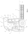
- As known in prior art (
figure 1 ) heavy vehicles 1' such as trucks comprise a cab 2' carried by a chassis 4' movable on ground, e.g. by wheels. - The cab 2' comprises a plurality of walls delimiting a space 3' configured to house a driver's seat assembly and usually a
bed assembly 5 carried by one of the walls of the cab 2' above the driver's seat assembly. - Always as known, in order to reduce pollution emissions of heavy vehicles, it is known to electrify the generation of torque provided to the wheels by providing so-called e-axles, fuel cell tractions systems or natural gas engines.
- The aforementioned environmental friendly tractions systems needs additional space on the vehicle 1' due to the presence of auxiliary elements 10' such as battery means or fuel storage tanks, that are usually carried on the chassis 4' in a rear position along longitudinal axis A' of the vehicle 1' with respect to the cab 2' .
- It is self-evident that the presence of auxiliary elements 10' on the chassis 4' rear the
cabin 2 reduces the useful space on the chassis 4' that needs to be elongated to allow the connection of the trailer thereon, i.e. to allow a correct position of the fifth-wheel mechanism, or by reducing the loadable area of the vehicle 1'. - Accordingly, a longer chassis 4' requires a three axles support with consequently increase of costs due to the longer manufacturing and additional elements needed.
- Moreover, the presence of a longer chassis 4' with three axles increases the costs related to the mission of the vehicle 1' due to greater taxes due to the number of the axle.
- Furthermore, the presence of further axles and of a longer chassis increases its weight with consequently reduction of autonomy and loss of efficiency.
- Therefore, the need is felt to avoid the use of longer chassis to reduce related drawbacks as described above.
- An aim of the present invention is to satisfy the above mentioned needs in a cost-effective and optimized manner.
- The aforementioned aim is reached by a vehicular cabin and a vehicle as claimed in the appended set of claims.
- For a better understanding of the present invention, a preferred embodiment is described in the following, by way of a non-limiting example, with reference to the attached drawings wherein:
-
Figure 1 is a schematic lateral view of a vehicular cabin as known in the art; -
Figure 2 is a schematic lateral view of a vehicular cabin according to a first embodiment of the invention; and -
Figure 3 is a schematic lateral view of a vehicular cabin according to a second embodiment of the invention. -
Figures 2 and3 discloses two embodiments of acabin 2 for a work vehicle 1 according to the invention. - The work vehicle 1 comprises a
cabin 2 carried by achassis 3 that is movable on ground, for instance as disclosed thanks towheels 4 carried by a respective axle (not shown). - The
cabin 2 delimit aspace 5 with respect to the environment configured to house the driver. Thecabin 2 essentially comprises atop wall 2a, arear wall 2b,front wall 2c, and afloor 2d that are connected together with a pair of lateral walls (not shown) thespace 5. - The
front wall 2c and therear wall 2b are spaced along a longitudinal axis A of the vehicle 1 while thefloor 2d and thetop wall 2a are spaced along a vertical axis B of the vehicle that is perpendicular to the longitudinal axis A. - The vehicle 1 further comprises a
driver seat assembly 6 housed withinspace 5 configured to provide a seat for the driver to drive the vehicle 1. - The vehicle 1 further comprises a bed assembly 7 housed within
space 5 and configured to provide a bed for allowing the driver to rest. The bed assembly 7 essentially comprises a bed 8 housed vertically above theseat assembly 5. - According to the invention, the
rear wall 2b of thecabin 2 is shaped in order to delimit with chassis 3 aspace 11 configured to houseauxiliary elements 12 of the vehicle 1. In detail,space 11 is delimited along longitudinal axis byrear wall 2b on one side and opened to the environment on the other side and is delimited along vertical axis B by therear wall 2b on a first side and by thechassis 3 on the other side. - In detail the
rear wall 2b defines ashoulder portion 2b' configured to defines theaforementioned space 11 to house theauxiliary elements 12 of the vehicle 1. - With
auxiliary elements 12 it is intended elements configured to store fluid or gaseous compounds, such as tanks, for being used by fuel cells or gas engines of the vehicle or battery assemblies to exchange energy with electric machines of the vehicle. -
Shoulder 2b' comprises essentially afirst wall 13 andsecond wall 14. Thefirst wall 13 extends between a remaining portion of therear wall 2b along longitudinal axis A and thesecond wall 14 extends from thefirst wall 13, opposite to the portion connected to the remaining portion ofrear wall 2b and thefloor 2d. Accordingly,shoulder 2b' has a substantially L-shaped cross-section in a plane delimited by longitudinal and vertical axis A, B. - In both embodiments, the
first wall 13 is configured on the side faced tospace 5, to support at least a portion of the bed assembly 7, i.e. to directly support a portion of bed 8. - In both embodiments the
second wall 14 is faced rear to theseat assembly 6 and may be realized distanced (as shown) along longitudinal axis A direction or in contact with this latter. - In the first embodiment (
figure 2 ), the bed 8 is carried in a cantilevered fashion by thefirst wall 13. In the second embodiment (figure 3 ) the bed 8 is substantially entirely supported vertically by thefirst wall 13 along the direction of the longitudinal axis A. - In such second embodiment, therefore, the
space 11 has a further extension along longitudinal axis A that can be freely used to store greaterauxiliary elements 12 or to other uses, such as to store further elements. - In view of the foregoing, the advantages of a cabin and a vehicle according to the invention are apparent.
- Thanks to the presence of
shoulder portion 2b' in therear wall 2b of thecabin 2, it is possible to define aspace 11 suitable for housing theauxiliary elements 12 thereby avoiding the need of alonger chassis 3. - In this way, the related drawbacks related to the use of
longer chassis 3 are avoided. - Furthermore, the possible variation of the length of the
first wall 13 allows to provide aspace 11 that can have a variable extension along the longitudinal axis according to the need of the vehicle, i.e. to the need of bed system 7, of storing objects or of housingauxiliary elements 12. - In particular, in the first embodiment, the overall dimension in longitudinal axis A of the cabin 1 plus
auxiliary elements 12, can remain sensibly the same as the length of cabin of the prior art, therefore new useful spaces are created without altering the overall dimensions of the vehicle 1. - Conversely, in the second embodiment, the length of the cabin along longitudinal axis A is increased, but in a limited way and permitted for new regulations related to low pollutants vehicle.
- It is clear that modifications can be made to the described cabin and vehicle which do not extend beyond the scope of protection defined by the claims.
- For example, the length of the
first wall 13 of theshoulder portion 2b' may vary according to the specific need of the vehicle 1. - Moreover, the
second wall 14 could extend along vertical axis B inclined with this latter. - Furthermore, instead of bed assembly 7, the vehicle may comprise storing elements configured to be carried, cantilevered or entirely, by the
first wall 13.
Claims (8)
- Cabin (2) for a heavy vehicle (1) provided with a chassis (3), said cabin (2) extending along a longitudinal axis (A) and a vertical axis (B) and delimiting a space (5) for housing a driver of said heavy vehicle (1), said cabin (2) comprising a top wall (2a) and a floor (2d) spaced along said vertical axis (B) a front wall (2c) and a rear wall (2b) spaced along said longitudinal axis (A) and a pair of lateral walls, said top wall (2a), said floor (2d), said rear wall (2b), said front wall (2c) and said lateral walls being connected to delimit said space (5),
characterized in that said rear wall (2b) comprises a shoulder portion (2b') configured to delimit a space (11) with respect to said chassis (3), said space (11) being configured to house auxiliary elements (12) of said vehicle (1), whereinsaid space (11) is delimited along said longitudinal axis (A) by said rear wall (2b) on one side and opened to environment on the other side and is delimited along said vertical axis (B) by said rear wall (2b) on a first side and by said chassis (3) on the other side. - Cabin according to claim 1, wherein said shoulder portion (2b') has a "L-shaped" cross-section along a plane defined by said longitudinal and vertical axes (A, B).
- Cabin according to any of the preceding claims, wherein said shoulder portion (2b') comprises a first wall (13) parallel to said longitudinal axis (A) and a second wall (14) extending along said vertical axis (B), said cabin (2) further comprising a seat assembly (6), said second wall (14) being rear faced to said seat assembly (6).
- Cabin according to claim 3, wherein said cabin (2) comprises a bed assembly (7), said bed assembly (7) being carried in a cantilevered way by said first wall (13) above said seat assembly (6).
- Cabin according to claim 3, wherein said cabin (2) comprises a bed assembly (7), said bed assembly (7) being entirely supported along said longitudinal axis (A) by said first wall (13) above said seat assembly (6).
- Cabin according to claim 3, wherein said cabin (2) defines a storing space/assembly between said first wall (11) and said roof (2a) within said space (5).
- Heavy vehicle (1) comprising a cabin (2) according to any of the preceding claims and a chassis (3) movable on ground and carrying said cabin (2).
- Heavy vehicle according to claim 7, wherein said auxiliary elements (12) comprises at least one among tanks and/or battery assemblies.
Applications Claiming Priority (1)
| Application Number | Priority Date | Filing Date | Title |
|---|---|---|---|
| IT202300018381 | 2023-09-07 |
Publications (1)
| Publication Number | Publication Date |
|---|---|
| EP4520639A1 true EP4520639A1 (en) | 2025-03-12 |
Family
ID=88690017
Family Applications (1)
| Application Number | Title | Priority Date | Filing Date |
|---|---|---|---|
| EP24198602.5A Pending EP4520639A1 (en) | 2023-09-07 | 2024-09-05 | Improved cabin for a heavy vehicle |
Country Status (1)
| Country | Link |
|---|---|
| EP (1) | EP4520639A1 (en) |
Citations (4)
| Publication number | Priority date | Publication date | Assignee | Title |
|---|---|---|---|---|
| US5906411A (en) * | 1997-06-20 | 1999-05-25 | New Holland North America, Inc. | Combine harvester cab layout for visibility, serviceability and space |
| EP2581504A1 (en) * | 2010-06-09 | 2013-04-17 | Hitachi Construction Machinery Co., Ltd. | Construction machine |
| AT13818U2 (en) * | 2014-05-23 | 2014-09-15 | Norbert Schrattenecker | Truck cab with superimposed floor levels (floor lines) |
| DE102016205047A1 (en) * | 2016-03-24 | 2017-09-28 | Kässbohrer Geländefahrzeug AG | Civil tracked vehicle |
-
2024
- 2024-09-05 EP EP24198602.5A patent/EP4520639A1/en active Pending
Patent Citations (4)
| Publication number | Priority date | Publication date | Assignee | Title |
|---|---|---|---|---|
| US5906411A (en) * | 1997-06-20 | 1999-05-25 | New Holland North America, Inc. | Combine harvester cab layout for visibility, serviceability and space |
| EP2581504A1 (en) * | 2010-06-09 | 2013-04-17 | Hitachi Construction Machinery Co., Ltd. | Construction machine |
| AT13818U2 (en) * | 2014-05-23 | 2014-09-15 | Norbert Schrattenecker | Truck cab with superimposed floor levels (floor lines) |
| DE102016205047A1 (en) * | 2016-03-24 | 2017-09-28 | Kässbohrer Geländefahrzeug AG | Civil tracked vehicle |
Similar Documents
| Publication | Publication Date | Title |
|---|---|---|
| EP3840972B1 (en) | Battery system for heavy duty vehicles | |
| US20240116357A1 (en) | Utility vehicle | |
| US9180777B2 (en) | Rear integration of a suspension system and fuel tanks in fuel cell vehicles | |
| EP3984864B1 (en) | Electric truck | |
| JP6380328B2 (en) | Vehicle underfloor structure | |
| US10919575B1 (en) | Vehicle chassis platform | |
| US11260909B2 (en) | Vehicle chassis platform | |
| KR20190124368A (en) | Battery case for vehicle | |
| KR20090023762A (en) | Upper Body Structure for Fuel Cell Vehicle to Reinforce Floor Kick-up Part | |
| CN113891828B (en) | Electric truck frame | |
| US20020121772A1 (en) | Vehicle with fuel tank | |
| US12005958B2 (en) | Universal chassis frame with variable rear axle positions for medium/heavy duty configurable electric trucks | |
| US20240208315A1 (en) | Universal chassis frame for medium-duty configurable electric trucks | |
| JP2019189168A (en) | Vehicular battery housing, vehicular battery pack, and electric vehicle | |
| US20260054560A1 (en) | Wheelbase structure | |
| US20250178422A2 (en) | Modular Motor Vehicle Architecture | |
| US20230158876A1 (en) | Structural assembly and vehicle having structural assembly | |
| US20220185382A1 (en) | Vehicle Body | |
| CN113795401A (en) | Motor vehicle group with a battery-driven vehicle and/or a hybrid-driven vehicle and/or a fuel cell-driven vehicle and/or an internal combustion engine-driven vehicle | |
| CN111532119B (en) | Chassis layout structure of a dual-drive dual-steering electric transport vehicle without a cab | |
| CN212667099U (en) | Double-drive double-steering electric transport vehicle chassis arrangement structure without cab | |
| US20240387915A1 (en) | Stackable battery | |
| US12365390B2 (en) | Structural assembly for vehicle | |
| CN215793162U (en) | Arrangement structure of heavy-duty LNG gas cylinder | |
| WO2024177553A1 (en) | Vehicle comprising a main frame and a subframe |
Legal Events
| Date | Code | Title | Description |
|---|---|---|---|
| PUAI | Public reference made under article 153(3) epc to a published international application that has entered the european phase |
Free format text: ORIGINAL CODE: 0009012 |
|
| STAA | Information on the status of an ep patent application or granted ep patent |
Free format text: STATUS: THE APPLICATION HAS BEEN PUBLISHED |
|
| AK | Designated contracting states |
Kind code of ref document: A1 Designated state(s): AL AT BE BG CH CY CZ DE DK EE ES FI FR GB GR HR HU IE IS IT LI LT LU LV MC ME MK MT NL NO PL PT RO RS SE SI SK SM TR |
|
| STAA | Information on the status of an ep patent application or granted ep patent |
Free format text: STATUS: REQUEST FOR EXAMINATION WAS MADE |
|
| 17P | Request for examination filed |
Effective date: 20250905 |