EP4520602A1 - Fluidic distribution system for cleaning vehicle surfaces - Google Patents
Fluidic distribution system for cleaning vehicle surfaces Download PDFInfo
- Publication number
- EP4520602A1 EP4520602A1 EP24197804.8A EP24197804A EP4520602A1 EP 4520602 A1 EP4520602 A1 EP 4520602A1 EP 24197804 A EP24197804 A EP 24197804A EP 4520602 A1 EP4520602 A1 EP 4520602A1
- Authority
- EP
- European Patent Office
- Prior art keywords
- tank
- air
- distribution system
- cleaning
- air pressure
- Prior art date
- Legal status (The legal status is an assumption and is not a legal conclusion. Google has not performed a legal analysis and makes no representation as to the accuracy of the status listed.)
- Pending
Links
Images


Classifications
-
- B—PERFORMING OPERATIONS; TRANSPORTING
- B60—VEHICLES IN GENERAL
- B60S—SERVICING, CLEANING, REPAIRING, SUPPORTING, LIFTING, OR MANOEUVRING OF VEHICLES, NOT OTHERWISE PROVIDED FOR
- B60S1/00—Cleaning of vehicles
- B60S1/02—Cleaning windscreens, windows or optical devices
- B60S1/56—Cleaning windscreens, windows or optical devices specially adapted for cleaning other parts or devices than front windows or windscreens
-
- B—PERFORMING OPERATIONS; TRANSPORTING
- B60—VEHICLES IN GENERAL
- B60S—SERVICING, CLEANING, REPAIRING, SUPPORTING, LIFTING, OR MANOEUVRING OF VEHICLES, NOT OTHERWISE PROVIDED FOR
- B60S1/00—Cleaning of vehicles
- B60S1/02—Cleaning windscreens, windows or optical devices
- B60S1/46—Cleaning windscreens, windows or optical devices using liquid; Windscreen washers
- B60S1/48—Liquid supply therefor
- B60S1/52—Arrangement of nozzles; Liquid spreading means
-
- B—PERFORMING OPERATIONS; TRANSPORTING
- B60—VEHICLES IN GENERAL
- B60S—SERVICING, CLEANING, REPAIRING, SUPPORTING, LIFTING, OR MANOEUVRING OF VEHICLES, NOT OTHERWISE PROVIDED FOR
- B60S1/00—Cleaning of vehicles
- B60S1/02—Cleaning windscreens, windows or optical devices
- B60S1/56—Cleaning windscreens, windows or optical devices specially adapted for cleaning other parts or devices than front windows or windscreens
- B60S1/60—Cleaning windscreens, windows or optical devices specially adapted for cleaning other parts or devices than front windows or windscreens for signalling devices, e.g. reflectors
-
- B—PERFORMING OPERATIONS; TRANSPORTING
- B60—VEHICLES IN GENERAL
- B60S—SERVICING, CLEANING, REPAIRING, SUPPORTING, LIFTING, OR MANOEUVRING OF VEHICLES, NOT OTHERWISE PROVIDED FOR
- B60S1/00—Cleaning of vehicles
- B60S1/02—Cleaning windscreens, windows or optical devices
- B60S1/46—Cleaning windscreens, windows or optical devices using liquid; Windscreen washers
- B60S1/48—Liquid supply therefor
- B60S1/481—Liquid supply therefor the operation of at least part of the liquid supply being controlled by electric means
-
- B—PERFORMING OPERATIONS; TRANSPORTING
- B60—VEHICLES IN GENERAL
- B60S—SERVICING, CLEANING, REPAIRING, SUPPORTING, LIFTING, OR MANOEUVRING OF VEHICLES, NOT OTHERWISE PROVIDED FOR
- B60S1/00—Cleaning of vehicles
- B60S1/02—Cleaning windscreens, windows or optical devices
- B60S1/46—Cleaning windscreens, windows or optical devices using liquid; Windscreen washers
- B60S1/48—Liquid supply therefor
- B60S1/50—Arrangement of reservoir
-
- B—PERFORMING OPERATIONS; TRANSPORTING
- B60—VEHICLES IN GENERAL
- B60S—SERVICING, CLEANING, REPAIRING, SUPPORTING, LIFTING, OR MANOEUVRING OF VEHICLES, NOT OTHERWISE PROVIDED FOR
- B60S1/00—Cleaning of vehicles
- B60S1/02—Cleaning windscreens, windows or optical devices
- B60S1/54—Cleaning windscreens, windows or optical devices using gas, e.g. hot air
Definitions
- the invention relates to the field of fluid distribution systems, in particular for the cleaning of surface sensors of vehicles.
- the invention relates to a fluid distribution system designed to allow the cleaning of surface sensors vehicles with pressurized air and pressurized cleaning liquid, pressurized air being almost devoid of humidity.
- sensors are located around the entire perimeter of the vehicle, for example in the bumpers and/or side skirts, and thus provide the driver or driving software with a complete view of the environment in which the vehicle is located.
- motor vehicles can be equipped with a cleaning system, in particular with ducts and nozzles for the distribution of cleaning fluids.
- the nozzles are located at the ends of the fluid distribution ducts and in the vicinity of the sensors.
- These cleaning systems can also include automatic valves allowing the selection of the sensor(s) to be cleaned and thus limiting the consumption of cleaning fluid.
- the document [1] cited at the end of the description discloses a system configured to clean, in particular automatically, the sensor surfaces of an autonomous vehicle.
- the system 200 is provided with two tanks.
- the system 200 includes a main tank 202 and another tank 208.
- the main tank 202 is configured to store a cleaning fluid at reduced pressure, such as atmospheric pressure, and is particularly implemented when cleaning surfaces that do not require consideration of high pressures.
- the main tank 202 can be used for cleaning a windshield or a rear window of a motor vehicle.
- the tank 208 for its part, is configured to store the cleaning fluid and to maintain it under pressure by means of a pressurized gas and is used in particular when the cleaning of surfaces requires pressures well above atmospheric pressure, for example above 4.8 bar.
- the tank 208 can be used for cleaning the surfaces of sensors of the motor vehicle.
- the system 200 also includes a pressurized gas source 206 and a pressure transfer means 204.
- the pressurized gas source 206 and the pressure transfer means 204 are configured to allow the tank 208 to be filled with cleaning fluid, from the main tank, and to pressurize said cleaning fluid by injection of pressurized gas.
- the system 200 disclosed in document [1] requires the implementation of a large capacity tank 208 in order to ensure sufficient autonomy for sensor cleaning. Also, maintaining a large volume of cleaning fluid under high pressure represents a danger for the vehicle housing it.
- This system particularly illustrated in figure 1 of [2], includes a cleaning fluid tank 50A and a gas tank 50B.
- the tanks 50A and 50B are further fluidly connected so as to allow compression of the cleaning fluid in the tank 50B.
- system described in document [2] includes a relatively large number of components/elements, which consequently makes it more complex to assemble and to use.
- the document [3] relates to a fluidic delivery system for cleaning surfaces of a vehicle, the delivery system comprising:
- the present invention concerns a fluidic distribution system for cleaning sensor surface of a vehicle, the distribution system comprising:
- said fluidic distribution system further comprises:
- the bottom of the air pressure tank is above the top, along the vertical direction, of the at least one intermediate tank so that a fluid likely to be present in the air pressure tank can flow, by gravity, through the connection means into the at least one intermediate tank.
- the at least one intermediate tank comprises two tanks said, respectively, first tank and second tank.
- connection means are configured so that the air can flow, selectively, in one and or the other of the first tank and the second tank.
- connection means comprise at least one valve, advantageously a multiway valve.
- compression means comprise a high-pressure pump or a compressor.
- the air dispensing means comprise at least one conduit, said air conduit, and at least one nozzle, said air nozzle.
- the air nozzle is equipped with a valve said air valve.
- the fluid dispensing means comprise at least one conduit, said fluid conduit, and at least one nozzle, said fluid nozzle.
- the fluid nozzle is equipped with a valve said fluid valve.
- connection means comprise a check valve configured to prevent air flowing from the at least one intermediate tank towards the air pressure tank.
- the invention also concerns the use of the fluidic distribution system according to the present invention for the cleaning of a sensor surface, the use comprising the following steps:
- the invention also concerns an automotive vehicle equipped with sensors and comprising a fluidic distribution system according to the present invention for the cleaning of the surface of the sensors.
- top and bottom are defined with respect to the vertical direction. It is therefore understood the “top” and the “bottom” of a component correspond to sections of said component while in use and according to the vertical direction.
- the present invention relates to a fluidic distribution system for cleaning the surface of sensors in a motor vehicle, and more particularly in an autonomous vehicle.
- the fluidic distribution system according to the present invention is particularly suitable for removing dust and/or dirt that may be present on the surface of the sensor(s) of a vehicle.
- sensors may include, but are not limited to, a camera, LIDAR, RADAR, or any other type of sensor that may be implemented in a motor vehicle.
- the fluidic distribution system according to the present invention may comprise nozzles configured to project cleaning fluid and/or pressurized air onto the surfaces of the sensors.
- the nozzles are arranged in proximity to the surfaces and may be static or movable.
- the invention relates to a fluidic distribution system for cleaning sensor surface of a vehicle, the distribution system comprising:
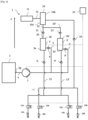
- the figure 1 illustrates a fluidic distribution system according to a first embodiment of the present invention.
- the fluidic distribution system 1 comprises a main tank 2 intended to store cleaning fluid, for example, at a pressure called main pressure.
- the main tank 2 has a volume, referred to as the main volume, of several liters, for example more than 3 liters, or even more than 4 liters.
- the main pressure may be less than 1.5 bar, and in particular equal to the atmospheric pressure.
- the fluidic distribution system 1 also includes at least one intermediate tank.
- the at least one intermediate tank comprises only one tank 3. It shall however be understood that the present invention is not limited to the sole consideration of a single tank 3.
- the description of the first embodiment gives the general principles of the invention so that the skill in art shall be able to adapt them to a plurality of intermediate tanks, notably 2 intermediate tanks 3 and 3' as set forth in a second embodiment.
- the intermediate tank 3 while in use, may be oriented with respect to the vertical axis z.
- the intermediate tank 3 comprises, along the vertical axis z, a bottom section 3a (said “bottom”) and a top section 3b (said “top”).
- the top 3b is directly above the bottom 3a.
- Tank 3 delimits a volume that is smaller than the main volume, advantageously which less than one third of the main volume, even more advantageously, less than one fifth of the main volume.
- the volume of tank 3 is less than 700 mL, advantageously less than 500 mL.
- the fluidic distribution system 1 also comprises main filling means configured to allow the filling of the tank 3 with cleaning fluid from the main tank 2.
- the main filling means may comprise conduits fluidically connecting the main tank 2 with the tank 3.
- the filling means may comprise a conduit 5 fluidically connecting the main tank 2 with the tank 3.
- the main filling means can also comprise a pump, called filling pump 7, interposed between the main tank 2 and the conduit 5.
- the filling pump 7 can notably comprise a pump (a low-pressure pump or a high-pressure pump).
- the filling pump 7 can be configured to take cleaning fluid from the main tank 2 and inject it into the conduit 5 at a pressure lower than 1.5 bar.
- the main filling means may further comprise a main conduit 8 fluidly connecting an outlet, called main outlet Sp, of the main tank 2 with the conduit 5.
- the filling pump 7 may be connected (disposed) on the main conduit 8.
- the main filling means may comprise a valve 9 disposed on the conduit 5.
- the valve 9 can comprise a solenoid valve, and more particularly a solenoid valve provided with a check valve.
- the fluidic distribution system also includes an air pressure tank 10.
- the air pressure tank 10 can be disposed above the tank 3 along the vertical direction z.
- the air pressure tank 10 comprises a bottom section 10a (said "bottom") and a top section 10b (said "top”).
- the air pressure tank 10 can be disposed so that the bottom 10a is above the top 3b.
- the general principle of the present invention does not impose this specific positioning of the air pressure tank with respect to the tank 3.
- the tank 3 and the air pressure tank 10 can positioned next to each other.
- the tank 3 and the air pressure tank 10 may be integral to each other.
- the tank 3 and the air pressure tank 10 can form a single piece.
- the fluidic distribution means 1 further comprise compression means configured to build up the air pressure of the air in the air pressure tank 10 in the 4 bar to 10 bar pressure range and in particular around 8 bars.
- the compression means can comprise a high-pressure pump 11 (or a compressor).
- the compression means can comprise a conduit 12 fluidically connecting the high-pressure pump 11 with the air pressure tank 10.
- the fluidic distribution system 1 also comprises connection means 20, typically a conduit, fluidically connecting the bottom 10a to the tank 3 so that, when the air pressure is built up, the air flowing from the air pressure tank 10 into the tank 3, via said connection means, pressurizes the cleaning fluid in said tank 3.
- connection means can comprise a check valve 21 configured to prevent air flowing from the at least one intermediate tank towards the air pressure tank.
- connection means 20 can connect the bottom 10a to top 3b of the tank 3.
- the fluidic distribution system 1 can further comprise fluid dispensing means configured to dispense (or spray) the cleaning fluid, from the bottom 3a of the tank 3, cleaning fluid, notably pressurized, for cleaning the surfaces of the sensors.
- the fluid dispensing means comprise at least one conduit, said fluid conduit 13, and at least one nozzle, said fluid nozzle 14A, 14B.
- the fluid dispensing means can further comprise fluid valves 15A, 15B, each fluid valve 15A and 15B being dedicated to a specific fluid nozzle 14A and 14B.
- the fluid conduits 13 can further comprise a check-valve 16 configured for preventing a back flow of the cleaning fluid into the tank 3.
- the fluidic distribution system 1 can further comprise air dispensing means configured to dispense (or spray) air from the air pressure tank for drying the surfaces of the sensors.
- the air dispensing means comprise at least one conduit, said air conduit 17, and at least one nozzle, said air nozzle 18A, 18B.
- the air dispensing means can further comprise air valves 19A, 19B, each air valve 19A and 19B being dedicated to a specific air nozzle 18A and 18B.
- the air conduit 17 can further comprise check-valve 24 configured for preventing a back flow of the air into the air pressure tank 10.
- the invention also concerns the use of the fluidic distribution system according to the present invention.
- the use of the fluidic distribution system comprises the following steps:
- Figure 2 illustrates the fluidic distribution system 1 according to the first embodiment of the present invention and wherein the tank 3 is partially filled with the cleaning fluid, the fluid level being indicated with the arrow A.
- FIG. 3 illustrates the fluidic distribution system 1 according to the first embodiment of the present invention and wherein the air pressure tank 10 is filled air likely to contain some humidity.
- the fluid dispensing means can also be configured to dispense the cleaning fluid from the bottom 3a' of the tank 3' cleaning fluid, notably pressurized, for cleaning the surfaces of the sensors.
- the fluid dispensing means comprise at least one conduit, said fluid conduit 13' (in addition to conduit 13), connecting the bottom 3a' to the fluid nozzle 14A, 14B associated to the fluid valves 15A., 15B.
- a check-valve 16' can also be arranged for preventing a back flow of the cleaning fluid into the tank 3'.
- connection means comprise at least one valve 22, advantageously a multiway valve 22.
- the at least one valve 22 is configured to selectively fluidically connect one and/or the other of the tank 3 and the tank 3' with the air pressure tank 10. This arrangement thus allows to selectively compress, with the pressurized air, the cleaning fluid contained in one or the other the tank 3 and the tank 3'.
- the main advantage of the implementation of the two tank 3 and 3' is to make possible to spray the cleaning fluid in a continuous manner as described in document [3].
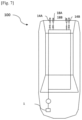
- the present invention also concerns an automotive vehicle 100 ( figure 7 ) equipped with sensors and comprising a fluidic distribution system according to the present invention for the cleaning of the surface of the sensors.
Landscapes
- Engineering & Computer Science (AREA)
- Mechanical Engineering (AREA)
- Water Supply & Treatment (AREA)
- Cleaning In General (AREA)
- Vehicle Cleaning, Maintenance, Repair, Refitting, And Outriggers (AREA)
Abstract
- a main tank (2) defining a main volume and intended to store a cleaning fluid;
- at least one intermediate tank (3) having an intermediate volume smaller than the main volume;
- main filling means configured to allow the filling of the at least one intermediate tank (3) with cleaning fluid from the main tank (2);
- an air pressure tank (10);
- compression means configured to build up the air pressure of the air in the air pressure tank (10);
- connection means fluidically connecting the bottom of the air pressure tank (10) to the at least one intermediate tank (3), advantageously the top of the at least one intermediate tank (3), so that, when the air pressure is built up, the air flowing from the air pressure tank (10) into the at least one intermediate tank (3), via said connection means, pressurizes the cleaning fluid in the at least one intermediate tank (3).
Description
- The invention relates to the field of fluid distribution systems, in particular for the cleaning of surface sensors of vehicles.
- More particularly, the invention relates to a fluid distribution system designed to allow the cleaning of surface sensors vehicles with pressurized air and pressurized cleaning liquid, pressurized air being almost devoid of humidity.
- Motor vehicles are now equipped with numerous sensors or cameras (hereinafter "sensors") for driving assistance purposes. These sensors are located around the entire perimeter of the vehicle, for example in the bumpers and/or side skirts, and thus provide the driver or driving software with a complete view of the environment in which the vehicle is located.
- However, these sensors, exposed to the environment, are likely to be covered with dirt or dust and, consequently, may see their performance degraded. Frequent cleanings of these sensors are therefore necessary to guarantee their performance.
- In this respect, motor vehicles can be equipped with a cleaning system, in particular with ducts and nozzles for the distribution of cleaning fluids. The nozzles are located at the ends of the fluid distribution ducts and in the vicinity of the sensors. These cleaning systems can also include automatic valves allowing the selection of the sensor(s) to be cleaned and thus limiting the consumption of cleaning fluid.
- In this regard, the document [1] cited at the end of the description discloses a system configured to clean, in particular automatically, the sensor surfaces of an autonomous vehicle.
- Notably, and as depicted in
Figure 2 of document [1], the system 200 is provided with two tanks. In particular, the system 200 includes a main tank 202 and another tank 208. - The main tank 202 is configured to store a cleaning fluid at reduced pressure, such as atmospheric pressure, and is particularly implemented when cleaning surfaces that do not require consideration of high pressures. For example, the main tank 202 can be used for cleaning a windshield or a rear window of a motor vehicle.
- The tank 208, for its part, is configured to store the cleaning fluid and to maintain it under pressure by means of a pressurized gas and is used in particular when the cleaning of surfaces requires pressures well above atmospheric pressure, for example above 4.8 bar. As an example, the tank 208 can be used for cleaning the surfaces of sensors of the motor vehicle.
- The system 200 also includes a pressurized gas source 206 and a pressure transfer means 204. In particular, the pressurized gas source 206 and the pressure transfer means 204 are configured to allow the tank 208 to be filled with cleaning fluid, from the main tank, and to pressurize said cleaning fluid by injection of pressurized gas.
- However, such a system is not satisfactory.
- Indeed, the system 200 disclosed in document [1] requires the implementation of a large capacity tank 208 in order to ensure sufficient autonomy for sensor cleaning. Also, maintaining a large volume of cleaning fluid under high pressure represents a danger for the vehicle housing it.
- The document [2] cited at the end of the description also discloses a system configured to clean sensor surfaces of a vehicle.
- This system, particularly illustrated in
figure 1 of [2], includes a cleaning fluid tank 50A and a gas tank 50B. The tanks 50A and 50B are further fluidly connected so as to allow compression of the cleaning fluid in the tank 50B. - Nevertheless, this system is not satisfactory either.
- Indeed, the system described in document [2] requires the implementation of a large gas tank 50B which, like the system described in document [1], also represents a danger.
- Moreover, the system described in document [2] includes a relatively large number of components/elements, which consequently makes it more complex to assemble and to use.
- The aforementioned problems are solved by the fluid distribution system described in the document [3] cited at the end of the description.
- Notably, the document [3] relates to a fluidic delivery system for cleaning surfaces of a vehicle, the delivery system comprising:
- a main tank with a main volume and intended to store a cleaning fluid at a pressure called main pressure;
- two secondary tanks, called, respectively, the first and second tank, each having a volume, called secondary volume, smaller than the main volume;
- filling means configured to allow selective filling of both the first tank and the second tank with cleaning fluid from the main tank;
- compression means configured to inject air selectively into one and the other of the first tank and the second tank, and so as to impose a working pressure, higher than the main pressure, on the cleaning fluid likely to be present in the secondary tank in question;
- dispensing means configured to selectively dispense from either of the first and second tanks cleaning fluid and/or air for cleaning surfaces.
- However, there are situations for which the dispensed air may be humid.
- It is therefore an object of the present invention to provide a fluid distribution system for cleaning vehicle sensors and which dispenses both air and cleaning fluid under pressure, and wherein the dispensed air is almost dry.
- The present invention concerns a fluidic distribution system for cleaning sensor surface of a vehicle, the distribution system comprising:
- a main tank defining a main volume and intended to store a cleaning fluid;
- at least one intermediate tank having an intermediate volume smaller than the main volume;
- main filling means configured to allow the filling of the at least one intermediate tank with cleaning fluid from the main tank;
- an air pressure tank;
- compression means configured to build up the air pressure of the air in the air pressure tank;
- connection means fluidically connecting the bottom of the air pressure tank to the at least one intermediate tank, advantageously the top of the at least one intermediate tank, so that, when the air pressure is built up, the air flowing from the air pressure tank into the at least one intermediate tank, via said connection means, pressurizes the cleaning fluid in the at least one intermediate tank.
- According to one embodiment, said fluidic distribution system further comprises:
- fluid dispensing means configured to dispense the cleaning fluid from the bottom of the at least one intermediate tank the pressurized cleaning fluid for cleaning the surfaces;
- air dispensing means configured to dispense air from the air pressure tank for cleaning the surfaces.
- According to one embodiment, the bottom of the air pressure tank is above the top, along the vertical direction, of the at least one intermediate tank so that a fluid likely to be present in the air pressure tank can flow, by gravity, through the connection means into the at least one intermediate tank.
- According to one embodiment, the at least one intermediate tank comprises two tanks said, respectively, first tank and second tank.
- According to one embodiment, the connection means are configured so that the air can flow, selectively, in one and or the other of the first tank and the second tank.
- According to one embodiment, the connection means comprise at least one valve, advantageously a multiway valve.
- According to one embodiment, compression means comprise a high-pressure pump or a compressor.
- According to one embodiment, the air dispensing means comprise at least one conduit, said air conduit, and at least one nozzle, said air nozzle.
- According to one embodiment, the air nozzle is equipped with a valve said air valve.
- According to one embodiment, the fluid dispensing means comprise at least one conduit, said fluid conduit, and at least one nozzle, said fluid nozzle.
- According to one embodiment, the fluid nozzle is equipped with a valve said fluid valve.
- According to one embodiment, the connection means comprise a check valve configured to prevent air flowing from the at least one intermediate tank towards the air pressure tank.
- The invention also concerns the use of the fluidic distribution system according to the present invention for the cleaning of a sensor surface, the use comprising the following steps:
- a) a step of pressure building of air comprised in the high-pressure tank;
- b) a step of compressing cleaning fluid comprised in the at least one intermediate tank, said step being executed by the flowing of the pressurized air from the air pressure tank into the at least one intermediate tank;
- c) a step of dispensing the cleaning fluid and/or the pressurized air for cleaning the sensor surface.
- The invention also concerns an automotive vehicle equipped with sensors and comprising a fluidic distribution system according to the present invention for the cleaning of the surface of the sensors.
- Other features and advantages will be better understood after reading the following description of the fluidic distribution system according to the invention, provided as non-limiting examples only, with reference to the accompanying drawings in which:
- [
Fig. 1] Figure 1 is a schematic representation of a fluidic distribution system according to the first embodiment of the present invention; - [
Fig.2] Figure 2 illustrates the fluidic distribution system according to the first embodiment of the present invention and wherein the tank is partially filled with the cleaning fluid, the fluid level being indicated with the arrow A; - [
Fig.3] Figure 3 illustrates the fluidic distribution system according to the first embodiment of the present invention and wherein the air pressure tank is filled air likely to contain some humidity; - [
Fig.4] Figure 4 illustrates the fluidic distribution system according after execution of step a) of the use of said fluidic distribution system; - [
Fig. 5] Figure 5 illustrates the fluidic distribution system according after execution of step b) of the use of said fluidic distribution system; - [
Fig.6] Figure 6 is a schematic representation of a fluidic distribution system according to a second embodiment of the present invention; - [
Fig.7] Figure 7 is a schematic representation of an automotive vehicle equipped with sensors and comprising a fluidic distribution system according to the present invention for the cleaning of the surface of the sensors. - Reference will now be made in detail to embodiments of the present invention, examples of which are illustrated in the accompanying drawings. It is to be understood that other embodiments may be utilized, and structural and functional changes may be made without departing from the scope of the present invention. Moreover, features of the embodiments may be combined, switched, or altered without departing from the scope of the present invention.
- As such, the following description is presented by way of illustration and does not limit the various alternatives and modifications that can be made to the illustrated embodiments and still within the spirit and scope of the present invention.
- As used herein, the words "top" and "bottom" are defined with respect to the vertical direction. It is therefore understood the "top" and the "bottom" of a component correspond to sections of said component while in use and according to the vertical direction.
- The present invention relates to a fluidic distribution system for cleaning the surface of sensors in a motor vehicle, and more particularly in an autonomous vehicle.
- In this regard, the fluidic distribution system according to the present invention is particularly suitable for removing dust and/or dirt that may be present on the surface of the sensor(s) of a vehicle.
- These sensors may include, but are not limited to, a camera, LIDAR, RADAR, or any other type of sensor that may be implemented in a motor vehicle. In particular, the fluidic distribution system according to the present invention may comprise nozzles configured to project cleaning fluid and/or pressurized air onto the surfaces of the sensors. In this regard, the nozzles are arranged in proximity to the surfaces and may be static or movable.
- Thus, the invention relates to a fluidic distribution system for cleaning sensor surface of a vehicle, the distribution system comprising:
- a main tank defining a main volume and intended to store a cleaning fluid;
- at least one intermediate tank having an intermediate volume smaller than the main volume;
- main filling means configured to allow the filling of the at least one intermediate tank with cleaning fluid from the main tank;
- an air pressure tank;
- compression means configured to build up the air pressure of the air in the air pressure tank;
- connection means fluidically connecting the bottom of the air pressure tank to the at least one intermediate tank so that, when the air pressure is built up, the air flowing from the air pressure tank into the at least one intermediate tank, via said connection means, pressurizes the cleaning fluid in the at least one intermediate tank;
- fluid dispensing means configured to dispense the cleaning fluid from the bottom of the at least one intermediate tank the pressurized cleaning fluid for cleaning the surfaces;
- air dispensing means configured to dispense air from the air pressure tank for drying the surfaces.
- The
figure 1 illustrates a fluidic distribution system according to a first embodiment of the present invention. - In particular, the
fluidic distribution system 1 comprises amain tank 2 intended to store cleaning fluid, for example, at a pressure called main pressure. In particular, themain tank 2 has a volume, referred to as the main volume, of several liters, for example more than 3 liters, or even more than 4 liters. The main pressure may be less than 1.5 bar, and in particular equal to the atmospheric pressure. - The
fluidic distribution system 1 also includes at least one intermediate tank. In this first embodiment, the at least one intermediate tank comprises only onetank 3. It shall however be understood that the present invention is not limited to the sole consideration of asingle tank 3. In particular, the description of the first embodiment gives the general principles of the invention so that the skill in art shall be able to adapt them to a plurality of intermediate tanks, notably 2intermediate tanks 3 and 3' as set forth in a second embodiment. - The
intermediate tank 3, while in use, may be oriented with respect to the vertical axis z. Notably, theintermediate tank 3 comprises, along the vertical axis z, abottom section 3a (said "bottom") and atop section 3b (said "top"). In other words, the top 3b is directly above the bottom 3a. -
Tank 3 delimits a volume that is smaller than the main volume, advantageously which less than one third of the main volume, even more advantageously, less than one fifth of the main volume. For example, the volume oftank 3 is less than 700 mL, advantageously less than 500 mL. - The
fluidic distribution system 1 according to the present invention also comprises main filling means configured to allow the filling of thetank 3 with cleaning fluid from themain tank 2. - In particular, the main filling means may comprise conduits fluidically connecting the
main tank 2 with thetank 3. Thus, the filling means may comprise aconduit 5 fluidically connecting themain tank 2 with thetank 3. - The main filling means can also comprise a pump, called filling
pump 7, interposed between themain tank 2 and theconduit 5. The fillingpump 7 can notably comprise a pump (a low-pressure pump or a high-pressure pump). For example, the fillingpump 7 can be configured to take cleaning fluid from themain tank 2 and inject it into theconduit 5 at a pressure lower than 1.5 bar. - The main filling means may further comprise a
main conduit 8 fluidly connecting an outlet, called main outlet Sp, of themain tank 2 with theconduit 5. In this respect, the fillingpump 7 may be connected (disposed) on themain conduit 8. - In particular, and as illustrated in
figure 1 , the main filling means may comprise avalve 9 disposed on theconduit 5. - The
valve 9 can comprise a solenoid valve, and more particularly a solenoid valve provided with a check valve. - The fluidic distribution system also includes an
air pressure tank 10. Advantageously, theair pressure tank 10 can be disposed above thetank 3 along the vertical direction z. Theair pressure tank 10 comprises abottom section 10a (said "bottom") and atop section 10b (said "top"). In addition, theair pressure tank 10 can be disposed so that the bottom 10a is above the top 3b. According to the present invention, other configuration can be contemplated. In particular, the general principle of the present invention does not impose this specific positioning of the air pressure tank with respect to thetank 3. Notably, as a non-limiting example, thetank 3 and theair pressure tank 10 can positioned next to each other. In addition, thetank 3 and theair pressure tank 10 may be integral to each other. In particular, thetank 3 and theair pressure tank 10 can form a single piece. - The fluidic distribution means 1 further comprise compression means configured to build up the air pressure of the air in the
air pressure tank 10 in the 4 bar to 10 bar pressure range and in particular around 8 bars. To this regard, the compression means can comprise a high-pressure pump 11 (or a compressor). - The compression means can comprise a
conduit 12 fluidically connecting the high-pressure pump 11 with theair pressure tank 10. - The
fluidic distribution system 1 also comprises connection means 20, typically a conduit, fluidically connecting the bottom 10a to thetank 3 so that, when the air pressure is built up, the air flowing from theair pressure tank 10 into thetank 3, via said connection means, pressurizes the cleaning fluid in saidtank 3. The connection means can comprise acheck valve 21 configured to prevent air flowing from the at least one intermediate tank towards the air pressure tank. In very advantageous embodiment, connection means 20 can connect the bottom 10a to top 3b of thetank 3. - The
fluidic distribution system 1 can further comprise fluid dispensing means configured to dispense (or spray) the cleaning fluid, from the bottom 3a of thetank 3, cleaning fluid, notably pressurized, for cleaning the surfaces of the sensors. - To this regard, the fluid dispensing means comprise at least one conduit, said
fluid conduit 13, and at least one nozzle, saidfluid nozzle 14A, 14B. - The fluid dispensing means can further comprise
fluid valves fluid valve fluid nozzle 14A and 14B. Thefluid conduits 13 can further comprise a check-valve 16 configured for preventing a back flow of the cleaning fluid into thetank 3. - The
fluidic distribution system 1 can further comprise air dispensing means configured to dispense (or spray) air from the air pressure tank for drying the surfaces of the sensors. - To this regard, the air dispensing means comprise at least one conduit, said
air conduit 17, and at least one nozzle, saidair nozzle 18A, 18B. - The air dispensing means can further comprise
air valves 19A, 19B, eachair valve 19A and 19B being dedicated to aspecific air nozzle 18A and 18B. Theair conduit 17 can further comprise check-valve 24 configured for preventing a back flow of the air into theair pressure tank 10. - The invention also concerns the use of the fluidic distribution system according to the present invention.
- Notably, the use of the fluidic distribution system comprises the following steps:
- a) a step of pressure building of air comprised in the high-pressure tank;
- b) a step of compressing cleaning fluid comprised in the at least one intermediate tank, said step being executed by the flowing of the pressurized air from the air pressure tank into the at least one intermediate tank;
- c) a step of dispensing the cleaning fluid and/or the pressurized air for cleaning the sensor surface.
-
Figure 2 illustrates thefluidic distribution system 1 according to the first embodiment of the present invention and wherein thetank 3 is partially filled with the cleaning fluid, the fluid level being indicated with the arrow A. -
Figure 3 illustrates thefluidic distribution system 1 according to the first embodiment of the present invention and wherein theair pressure tank 10 is filled air likely to contain some humidity. -
Figure 4 illustrates thefluidic distribution system 1 according to the first embodiment and wherein the air filling theair pressure tank 10 is pressurized by the compressor (step a)). The air pressure in the air pressure tank can be in the 4 bar to 10 bar pressure range so that the humidity contained in said air condenses (reference CW) and falls, by gravity, in thebottom section 10a. Condensed water then flows, essentially by overpressure, through the connection means into thetank 3. In other words, the overpressure is the main driver for the transfer of the condensed water towards thetank 3. - The pressurized air flows also into from the air pressure tank into the
tank 3, via said the connection means, and pressurizes the cleaning fluid in said tank 3 (step b),figure 5 ). The air flow stops when an air pressure balance is reached in both the air pressure tank and in thetank 3. The pressurized air after the execution of step b) is almost dry. - After the execution of step b), the fluidic distribution system is in conditions for spraying either cleaning fluid with the fluid nozzles or pressurized dry air with the air nozzles.
-
Figure 6 represents thefluidic distribution system 1 according to a second embodiment. This second embodiment essentially incorporates all of the features of the first embodiment. - Notably, this second embodiment differs from the first embodiment in that, it comprises a second intermediate tank said tank 3' (in addition to tank 3). In particular, said tank 3' is fluidically connected, from is top 3b' to the bottom 10a of the
air pressure tank 10 via the connection means. The connection means can comprise a check valve 21' to prevent any back flow of the air from the tank 3' towards theair pressure tank 10. - The fluid dispensing means can also be configured to dispense the cleaning fluid from the bottom 3a' of the tank 3' cleaning fluid, notably pressurized, for cleaning the surfaces of the sensors.
- To this regard, the fluid dispensing means comprise at least one conduit, said fluid conduit 13' (in addition to conduit 13), connecting the bottom 3a' to the
fluid nozzle 14A, 14B associated to the fluid valves 15A., 15B. A check-valve 16' can also be arranged for preventing a back flow of the cleaning fluid into the tank 3'. - Finally, the connection means comprise at least one
valve 22, advantageously amultiway valve 22. Notably the at least onevalve 22 is configured to selectively fluidically connect one and/or the other of thetank 3 and the tank 3' with theair pressure tank 10. This arrangement thus allows to selectively compress, with the pressurized air, the cleaning fluid contained in one or the other thetank 3 and the tank 3'. - The main advantage of the implementation of the two
tank 3 and 3' is to make possible to spray the cleaning fluid in a continuous manner as described in document [3]. - The present invention also concerns an automotive vehicle 100 (
figure 7 ) equipped with sensors and comprising a fluidic distribution system according to the present invention for the cleaning of the surface of the sensors. - Of course, the invention is not limited to the embodiments described and variant embodiments can be made without departing from the scope of the invention as defined by the claims.
-
- [1]
US10723325B2 - [2]
DE10 2019 125 970 A1 ; - [3]
EP 4 194 283 A1 .
Claims (14)
- A fluidic distribution system (1) for cleaning sensor surface of a vehicle, the distribution system comprising:- a main tank (2) defining a main volume and intended to store a cleaning fluid;- at least one intermediate tank (3, 3') having an intermediate volume smaller than the main volume;- main filling means configured to allow the filling of the at least one intermediate tank (3, 3') with cleaning fluid from the main tank (2);- an air pressure tank (10);- compression means configured to build up the air pressure of the air in the air pressure tank (10);- connection means fluidically connecting the bottom of the air pressure tank (10) to the at least one intermediate tank (3, 3'), advantageously the top of the at least one intermediate tank (3, 3'), so that, when the air pressure is built up, the air flowing from the air pressure tank (10) into the at least one intermediate tank (3, 3'), via said connection means, pressurizes the cleaning fluid in the at least one intermediate tank (3, 3').
- The fluidic distribution system (1) according to claim 1, wherein said fluidic distribution system (1) further comprises:- fluid dispensing means configured to dispense the cleaning fluid from the bottom (3a, 3a') of the at least one intermediate tank (3, 3') the pressurized cleaning fluid for cleaning the surfaces;- air dispensing means configured to dispense air from the air pressure tank (10) for cleaning the surfaces.
- The fluidic distribution system (1) according to claim 1 or 2, wherein the bottom of the air pressure tank (10) is above the top (3b, 3b'), along the vertical direction, of the at least one intermediate tank (3, 3') so that a fluid likely to be present in the air pressure tank (10) can flow, by gravity, through the connection means into the at least one intermediate tank (3, 3').
- The fluidic distribution system (1) according to any one of claims 1 to 3, wherein the at least one intermediate tank (3, 3') comprises two tanks said, respectively, first tank (3) and second tank (3').
- The fluidic distribution system (1) according to claim 4, wherein the connection means are configured so that the air can flow, selectively, in one and or the other of the first tank (3) and the second tank (3').
- The fluidic distribution system (1) according to claim 5, wherein the connection means comprise at least one valve, advantageously a multiway valve (22).
- The fluidic distribution system (1) according to any of claims 1 to 6, wherein compression means comprise a high-pressure pump (11) or a compressor.
- The fluidic distribution system (1) according to any of claims 1 to 6 in combination with claim 2, wherein the air dispensing means comprise at least one conduit, said air conduit (17), and at least one nozzle, said air nozzle (18A, 18B).
- The fluidic distribution system (1) according to claim 8, wherein the air nozzle (18A, 18B) is equipped with a valve said air valve (19A, 19B).
- The fluidic distribution system (1) according to any of claims 1 to 9 in combination with claim 2, wherein the fluid dispensing means comprise at least one conduit, said fluid conduit (13), and at least one nozzle, said fluid nozzle (14A, 14B).
- The fluidic distribution system (1) according to claim 10, wherein the fluid nozzle is equipped with a valve said fluid valve (15A, 15B).
- The fluidic distribution system (1) according to any of claims 1 to 11, wherein the connection means comprise a check valve (21) configured to prevent air flowing from the at least one intermediate tank (3, 3') towards the air pressure tank (10).
- Use of the fluidic distribution system (1) according to any of claim 1 to 12 for the cleaning of a sensor surface, the use comprising the following steps:a) a step of pressure building of air comprised in the high-pressure tank;b) a step of compressing cleaning fluid comprised in the at least one intermediate tank (3, 3'), said step being executed by the flowing of the pressurized air from the air pressure tank (10) into the at least one intermediate tank (3, 3');c) a step of dispensing the cleaning fluid and/or the pressurized air for cleaning the sensor surface.
- Automotive vehicle equipped with sensors and comprising a fluidic distribution system (1) according to any of claims 1 to 12 for the cleaning of the surface of the sensors.
Applications Claiming Priority (1)
| Application Number | Priority Date | Filing Date | Title |
|---|---|---|---|
| FR2309529A FR3152773B1 (en) | 2023-09-11 | 2023-09-11 | Fluid distribution system for cleaning vehicle surfaces |
Publications (1)
| Publication Number | Publication Date |
|---|---|
| EP4520602A1 true EP4520602A1 (en) | 2025-03-12 |
Family
ID=88839392
Family Applications (1)
| Application Number | Title | Priority Date | Filing Date |
|---|---|---|---|
| EP24197804.8A Pending EP4520602A1 (en) | 2023-09-11 | 2024-09-02 | Fluidic distribution system for cleaning vehicle surfaces |
Country Status (4)
| Country | Link |
|---|---|
| US (1) | US20250083645A1 (en) |
| EP (1) | EP4520602A1 (en) |
| CN (1) | CN119590371A (en) |
| FR (1) | FR3152773B1 (en) |
Families Citing this family (1)
| Publication number | Priority date | Publication date | Assignee | Title |
|---|---|---|---|---|
| DE102022118856A1 (en) * | 2022-07-27 | 2024-02-01 | Kautex Textron Gmbh & Co. Kg | Method for controlling a cleaning system for motor vehicle components, cleaning system for motor vehicle components and motor vehicle with cleaning system for motor vehicle components |
Citations (5)
| Publication number | Priority date | Publication date | Assignee | Title |
|---|---|---|---|---|
| US10737662B2 (en) * | 2018-06-27 | 2020-08-11 | Seeva Technologies, Inc. | Systems and methods for perception surface cleaning, drying, and/or thermal management with fluid recirculation |
| DE102020202570A1 (en) * | 2020-02-28 | 2021-09-02 | Vitesco Technologies GmbH | Cleaning device |
| US20210402961A1 (en) * | 2020-06-26 | 2021-12-30 | Clear Lens Robotics | Automated fluid dispensing systems for cleaning vision-based surfaces |
| US20220017047A1 (en) * | 2019-09-26 | 2022-01-20 | Joma-Polytec Gmbh | Sensor Cleaning System for Vehicles |
| EP4194283A1 (en) | 2021-12-08 | 2023-06-14 | A. Raymond et Cie | Fluidic distribution system for cleaning vehicle surfaces |
-
2023
- 2023-09-11 FR FR2309529A patent/FR3152773B1/en active Active
-
2024
- 2024-09-02 EP EP24197804.8A patent/EP4520602A1/en active Pending
- 2024-09-10 CN CN202411263510.8A patent/CN119590371A/en active Pending
- 2024-09-11 US US18/830,732 patent/US20250083645A1/en active Pending
Patent Citations (6)
| Publication number | Priority date | Publication date | Assignee | Title |
|---|---|---|---|---|
| US10737662B2 (en) * | 2018-06-27 | 2020-08-11 | Seeva Technologies, Inc. | Systems and methods for perception surface cleaning, drying, and/or thermal management with fluid recirculation |
| US20220017047A1 (en) * | 2019-09-26 | 2022-01-20 | Joma-Polytec Gmbh | Sensor Cleaning System for Vehicles |
| DE102020202570A1 (en) * | 2020-02-28 | 2021-09-02 | Vitesco Technologies GmbH | Cleaning device |
| US20210402961A1 (en) * | 2020-06-26 | 2021-12-30 | Clear Lens Robotics | Automated fluid dispensing systems for cleaning vision-based surfaces |
| EP4194283A1 (en) | 2021-12-08 | 2023-06-14 | A. Raymond et Cie | Fluidic distribution system for cleaning vehicle surfaces |
| WO2023104551A1 (en) * | 2021-12-08 | 2023-06-15 | A. Raymond Et Cie | Fluidic distribution system for cleaning vehicle surfaces |
Also Published As
| Publication number | Publication date |
|---|---|
| FR3152773A1 (en) | 2025-03-14 |
| CN119590371A (en) | 2025-03-11 |
| FR3152773B1 (en) | 2025-08-22 |
| US20250083645A1 (en) | 2025-03-13 |
Similar Documents
| Publication | Publication Date | Title |
|---|---|---|
| EP4194283B1 (en) | Fluidic distribution system for cleaning vehicle surfaces | |
| US11124159B2 (en) | Washer fluid vehicle reservoir | |
| EP4520602A1 (en) | Fluidic distribution system for cleaning vehicle surfaces | |
| EP2223594B1 (en) | Agricultural sprayer | |
| CA2427630A1 (en) | Fuel tank | |
| JP4452098B2 (en) | Fuel delivery system and method | |
| JP2007051633A (en) | Fuel delivery system of combustion engine | |
| US20200070194A1 (en) | Modified impingement spray nozzle | |
| US20180141522A1 (en) | Washer fluid vehicle reservoir | |
| CN115348929B (en) | Liquid injection system | |
| JP4358826B2 (en) | Fuel supply device | |
| US6305393B1 (en) | Flushing system with pressurized air | |
| US20200070978A1 (en) | Concentric pump spray system | |
| JP7587706B2 (en) | Method for cleaning automotive surfaces | |
| US20190358565A1 (en) | Fuel filter for cleaning fuel for an internal combustion engine | |
| JP7537019B2 (en) | Automotive Washing Systems | |
| US11209840B2 (en) | Washer fluid system and delivery method | |
| EP4182261B1 (en) | Filter device for a fuel dispensing system | |
| US20210260500A1 (en) | Continuous Flow System For Draining Fuel-Water Separator | |
| CN115023375A (en) | Sensor cleaning system for a vehicle and method for cleaning a sensor | |
| JP2025511306A (en) | Systems and methods for fluid dispersion - Patents.com | |
| WO2025056334A1 (en) | Fluid distribution assembly for the cleaning of a sensor of a vehicle | |
| EP4124522B1 (en) | Fluid distribution assembly for the cleaning of a sensor of a vehicle | |
| EP2373511B1 (en) | Device for feeding fuel to an engine | |
| CN120693267A (en) | Wiper blade with directional valve |
Legal Events
| Date | Code | Title | Description |
|---|---|---|---|
| PUAI | Public reference made under article 153(3) epc to a published international application that has entered the european phase |
Free format text: ORIGINAL CODE: 0009012 |
|
| STAA | Information on the status of an ep patent application or granted ep patent |
Free format text: STATUS: REQUEST FOR EXAMINATION WAS MADE |
|
| 17P | Request for examination filed |
Effective date: 20240902 |
|
| AK | Designated contracting states |
Kind code of ref document: A1 Designated state(s): AL AT BE BG CH CY CZ DE DK EE ES FI FR GB GR HR HU IE IS IT LI LT LU LV MC ME MK MT NL NO PL PT RO RS SE SI SK SM TR |
|
| RIC1 | Information provided on ipc code assigned before grant |
Ipc: B60S 1/48 20060101AFI20260304BHEP Ipc: B60S 1/56 20060101ALI20260304BHEP Ipc: B60S 1/54 20060101ALI20260304BHEP |
|
| GRAP | Despatch of communication of intention to grant a patent |
Free format text: ORIGINAL CODE: EPIDOSNIGR1 |
|
| STAA | Information on the status of an ep patent application or granted ep patent |
Free format text: STATUS: GRANT OF PATENT IS INTENDED |