EP4520569A1 - Lighting apparatus for vehicle and manufacturing method thereof - Google Patents
Lighting apparatus for vehicle and manufacturing method thereof Download PDFInfo
- Publication number
- EP4520569A1 EP4520569A1 EP24183104.9A EP24183104A EP4520569A1 EP 4520569 A1 EP4520569 A1 EP 4520569A1 EP 24183104 A EP24183104 A EP 24183104A EP 4520569 A1 EP4520569 A1 EP 4520569A1
- Authority
- EP
- European Patent Office
- Prior art keywords
- lighting apparatus
- transmission member
- lighting
- shielding member
- light guide
- Prior art date
- Legal status (The legal status is an assumption and is not a legal conclusion. Google has not performed a legal analysis and makes no representation as to the accuracy of the status listed.)
- Pending
Links
Images


Classifications
-
- G—PHYSICS
- G09—EDUCATION; CRYPTOGRAPHY; DISPLAY; ADVERTISING; SEALS
- G09F—DISPLAYING; ADVERTISING; SIGNS; LABELS OR NAME-PLATES; SEALS
- G09F13/00—Illuminated signs; Luminous advertising
- G09F13/04—Signs, boards or panels, illuminated from behind the insignia
- G09F13/0418—Constructional details
- G09F13/0427—Constructional details in the form of buttons
-
- B—PERFORMING OPERATIONS; TRANSPORTING
- B29—WORKING OF PLASTICS; WORKING OF SUBSTANCES IN A PLASTIC STATE IN GENERAL
- B29C—SHAPING OR JOINING OF PLASTICS; SHAPING OF MATERIAL IN A PLASTIC STATE, NOT OTHERWISE PROVIDED FOR; AFTER-TREATMENT OF THE SHAPED PRODUCTS, e.g. REPAIRING
- B29C45/00—Injection moulding, i.e. forcing the required volume of moulding material through a nozzle into a closed mould; Apparatus therefor
- B29C45/14—Injection moulding, i.e. forcing the required volume of moulding material through a nozzle into a closed mould; Apparatus therefor incorporating preformed parts or layers, e.g. injection moulding around inserts or for coating articles
-
- B—PERFORMING OPERATIONS; TRANSPORTING
- B29—WORKING OF PLASTICS; WORKING OF SUBSTANCES IN A PLASTIC STATE IN GENERAL
- B29C—SHAPING OR JOINING OF PLASTICS; SHAPING OF MATERIAL IN A PLASTIC STATE, NOT OTHERWISE PROVIDED FOR; AFTER-TREATMENT OF THE SHAPED PRODUCTS, e.g. REPAIRING
- B29C45/00—Injection moulding, i.e. forcing the required volume of moulding material through a nozzle into a closed mould; Apparatus therefor
- B29C45/16—Making multilayered or multicoloured articles
- B29C45/1671—Making multilayered or multicoloured articles with an insert
-
- B—PERFORMING OPERATIONS; TRANSPORTING
- B60—VEHICLES IN GENERAL
- B60K—ARRANGEMENT OR MOUNTING OF PROPULSION UNITS OR OF TRANSMISSIONS IN VEHICLES; ARRANGEMENT OR MOUNTING OF PLURAL DIVERSE PRIME-MOVERS IN VEHICLES; AUXILIARY DRIVES FOR VEHICLES; INSTRUMENTATION OR DASHBOARDS FOR VEHICLES; ARRANGEMENTS IN CONNECTION WITH COOLING, AIR INTAKE, GAS EXHAUST OR FUEL SUPPLY OF PROPULSION UNITS IN VEHICLES
- B60K35/00—Instruments specially adapted for vehicles; Arrangement of instruments in or on vehicles
- B60K35/10—Input arrangements, i.e. from user to vehicle, associated with vehicle functions or specially adapted therefor
-
- B—PERFORMING OPERATIONS; TRANSPORTING
- B60—VEHICLES IN GENERAL
- B60Q—ARRANGEMENT OF SIGNALLING OR LIGHTING DEVICES, THE MOUNTING OR SUPPORTING THEREOF OR CIRCUITS THEREFOR, FOR VEHICLES IN GENERAL
- B60Q3/00—Arrangement of lighting devices for vehicle interiors; Lighting devices specially adapted for vehicle interiors
- B60Q3/10—Arrangement of lighting devices for vehicle interiors; Lighting devices specially adapted for vehicle interiors for dashboards
- B60Q3/14—Arrangement of lighting devices for vehicle interiors; Lighting devices specially adapted for vehicle interiors for dashboards lighting through the surface to be illuminated
-
- B—PERFORMING OPERATIONS; TRANSPORTING
- B60—VEHICLES IN GENERAL
- B60Q—ARRANGEMENT OF SIGNALLING OR LIGHTING DEVICES, THE MOUNTING OR SUPPORTING THEREOF OR CIRCUITS THEREFOR, FOR VEHICLES IN GENERAL
- B60Q3/00—Arrangement of lighting devices for vehicle interiors; Lighting devices specially adapted for vehicle interiors
- B60Q3/10—Arrangement of lighting devices for vehicle interiors; Lighting devices specially adapted for vehicle interiors for dashboards
- B60Q3/16—Circuits; Control arrangements
-
- B—PERFORMING OPERATIONS; TRANSPORTING
- B60—VEHICLES IN GENERAL
- B60Q—ARRANGEMENT OF SIGNALLING OR LIGHTING DEVICES, THE MOUNTING OR SUPPORTING THEREOF OR CIRCUITS THEREFOR, FOR VEHICLES IN GENERAL
- B60Q3/00—Arrangement of lighting devices for vehicle interiors; Lighting devices specially adapted for vehicle interiors
- B60Q3/60—Arrangement of lighting devices for vehicle interiors; Lighting devices specially adapted for vehicle interiors characterised by optical aspects
- B60Q3/62—Arrangement of lighting devices for vehicle interiors; Lighting devices specially adapted for vehicle interiors characterised by optical aspects using light guides
- B60Q3/64—Arrangement of lighting devices for vehicle interiors; Lighting devices specially adapted for vehicle interiors characterised by optical aspects using light guides for a single lighting device
-
- C—CHEMISTRY; METALLURGY
- C23—COATING METALLIC MATERIAL; COATING MATERIAL WITH METALLIC MATERIAL; CHEMICAL SURFACE TREATMENT; DIFFUSION TREATMENT OF METALLIC MATERIAL; COATING BY VACUUM EVAPORATION, BY SPUTTERING, BY ION IMPLANTATION OR BY CHEMICAL VAPOUR DEPOSITION, IN GENERAL; INHIBITING CORROSION OF METALLIC MATERIAL OR INCRUSTATION IN GENERAL
- C23C—COATING METALLIC MATERIAL; COATING MATERIAL WITH METALLIC MATERIAL; SURFACE TREATMENT OF METALLIC MATERIAL BY DIFFUSION INTO THE SURFACE, BY CHEMICAL CONVERSION OR SUBSTITUTION; COATING BY VACUUM EVAPORATION, BY SPUTTERING, BY ION IMPLANTATION OR BY CHEMICAL VAPOUR DEPOSITION, IN GENERAL
- C23C14/00—Coating by vacuum evaporation, by sputtering or by ion implantation of the coating forming material
- C23C14/06—Coating by vacuum evaporation, by sputtering or by ion implantation of the coating forming material characterised by the coating material
- C23C14/14—Metallic material, boron or silicon
-
- G—PHYSICS
- G02—OPTICS
- G02B—OPTICAL ELEMENTS, SYSTEMS OR APPARATUS
- G02B6/00—Light guides; Structural details of arrangements comprising light guides and other optical elements, e.g. couplings
- G02B6/0001—Light guides; Structural details of arrangements comprising light guides and other optical elements, e.g. couplings specially adapted for lighting devices or systems
- G02B6/0011—Light guides; Structural details of arrangements comprising light guides and other optical elements, e.g. couplings specially adapted for lighting devices or systems the light guides being planar or of plate-like form
- G02B6/0033—Means for improving the coupling-out of light from the light guide
- G02B6/005—Means for improving the coupling-out of light from the light guide provided by one optical element, or plurality thereof, placed on the light output side of the light guide
-
- G—PHYSICS
- G02—OPTICS
- G02B—OPTICAL ELEMENTS, SYSTEMS OR APPARATUS
- G02B6/00—Light guides; Structural details of arrangements comprising light guides and other optical elements, e.g. couplings
- G02B6/0001—Light guides; Structural details of arrangements comprising light guides and other optical elements, e.g. couplings specially adapted for lighting devices or systems
- G02B6/0011—Light guides; Structural details of arrangements comprising light guides and other optical elements, e.g. couplings specially adapted for lighting devices or systems the light guides being planar or of plate-like form
- G02B6/0065—Manufacturing aspects; Material aspects
-
- G—PHYSICS
- G09—EDUCATION; CRYPTOGRAPHY; DISPLAY; ADVERTISING; SEALS
- G09F—DISPLAYING; ADVERTISING; SIGNS; LABELS OR NAME-PLATES; SEALS
- G09F13/00—Illuminated signs; Luminous advertising
- G09F13/04—Signs, boards or panels, illuminated from behind the insignia
- G09F13/0418—Constructional details
- G09F13/044—Signs, boards or panels mounted on vehicles
-
- B—PERFORMING OPERATIONS; TRANSPORTING
- B60—VEHICLES IN GENERAL
- B60K—ARRANGEMENT OR MOUNTING OF PROPULSION UNITS OR OF TRANSMISSIONS IN VEHICLES; ARRANGEMENT OR MOUNTING OF PLURAL DIVERSE PRIME-MOVERS IN VEHICLES; AUXILIARY DRIVES FOR VEHICLES; INSTRUMENTATION OR DASHBOARDS FOR VEHICLES; ARRANGEMENTS IN CONNECTION WITH COOLING, AIR INTAKE, GAS EXHAUST OR FUEL SUPPLY OF PROPULSION UNITS IN VEHICLES
- B60K2360/00—Indexing scheme associated with groups B60K35/00 or B60K37/00 relating to details of instruments or dashboards
- B60K2360/128—Axially displaceable input devices for instruments
-
- B—PERFORMING OPERATIONS; TRANSPORTING
- B60—VEHICLES IN GENERAL
- B60K—ARRANGEMENT OR MOUNTING OF PROPULSION UNITS OR OF TRANSMISSIONS IN VEHICLES; ARRANGEMENT OR MOUNTING OF PLURAL DIVERSE PRIME-MOVERS IN VEHICLES; AUXILIARY DRIVES FOR VEHICLES; INSTRUMENTATION OR DASHBOARDS FOR VEHICLES; ARRANGEMENTS IN CONNECTION WITH COOLING, AIR INTAKE, GAS EXHAUST OR FUEL SUPPLY OF PROPULSION UNITS IN VEHICLES
- B60K2360/00—Indexing scheme associated with groups B60K35/00 or B60K37/00 relating to details of instruments or dashboards
- B60K2360/139—Clusters of instrument input devices
-
- B—PERFORMING OPERATIONS; TRANSPORTING
- B60—VEHICLES IN GENERAL
- B60K—ARRANGEMENT OR MOUNTING OF PROPULSION UNITS OR OF TRANSMISSIONS IN VEHICLES; ARRANGEMENT OR MOUNTING OF PLURAL DIVERSE PRIME-MOVERS IN VEHICLES; AUXILIARY DRIVES FOR VEHICLES; INSTRUMENTATION OR DASHBOARDS FOR VEHICLES; ARRANGEMENTS IN CONNECTION WITH COOLING, AIR INTAKE, GAS EXHAUST OR FUEL SUPPLY OF PROPULSION UNITS IN VEHICLES
- B60K2360/00—Indexing scheme associated with groups B60K35/00 or B60K37/00 relating to details of instruments or dashboards
- B60K2360/20—Optical features of instruments
- B60K2360/33—Illumination features
- B60K2360/332—Light emitting diodes
-
- B—PERFORMING OPERATIONS; TRANSPORTING
- B60—VEHICLES IN GENERAL
- B60K—ARRANGEMENT OR MOUNTING OF PROPULSION UNITS OR OF TRANSMISSIONS IN VEHICLES; ARRANGEMENT OR MOUNTING OF PLURAL DIVERSE PRIME-MOVERS IN VEHICLES; AUXILIARY DRIVES FOR VEHICLES; INSTRUMENTATION OR DASHBOARDS FOR VEHICLES; ARRANGEMENTS IN CONNECTION WITH COOLING, AIR INTAKE, GAS EXHAUST OR FUEL SUPPLY OF PROPULSION UNITS IN VEHICLES
- B60K2360/00—Indexing scheme associated with groups B60K35/00 or B60K37/00 relating to details of instruments or dashboards
- B60K2360/20—Optical features of instruments
- B60K2360/33—Illumination features
- B60K2360/336—Light guides
-
- B—PERFORMING OPERATIONS; TRANSPORTING
- B60—VEHICLES IN GENERAL
- B60K—ARRANGEMENT OR MOUNTING OF PROPULSION UNITS OR OF TRANSMISSIONS IN VEHICLES; ARRANGEMENT OR MOUNTING OF PLURAL DIVERSE PRIME-MOVERS IN VEHICLES; AUXILIARY DRIVES FOR VEHICLES; INSTRUMENTATION OR DASHBOARDS FOR VEHICLES; ARRANGEMENTS IN CONNECTION WITH COOLING, AIR INTAKE, GAS EXHAUST OR FUEL SUPPLY OF PROPULSION UNITS IN VEHICLES
- B60K2360/00—Indexing scheme associated with groups B60K35/00 or B60K37/00 relating to details of instruments or dashboards
- B60K2360/20—Optical features of instruments
- B60K2360/33—Illumination features
- B60K2360/34—Backlit symbols
-
- B—PERFORMING OPERATIONS; TRANSPORTING
- B60—VEHICLES IN GENERAL
- B60K—ARRANGEMENT OR MOUNTING OF PROPULSION UNITS OR OF TRANSMISSIONS IN VEHICLES; ARRANGEMENT OR MOUNTING OF PLURAL DIVERSE PRIME-MOVERS IN VEHICLES; AUXILIARY DRIVES FOR VEHICLES; INSTRUMENTATION OR DASHBOARDS FOR VEHICLES; ARRANGEMENTS IN CONNECTION WITH COOLING, AIR INTAKE, GAS EXHAUST OR FUEL SUPPLY OF PROPULSION UNITS IN VEHICLES
- B60K2360/00—Indexing scheme associated with groups B60K35/00 or B60K37/00 relating to details of instruments or dashboards
- B60K2360/77—Instrument locations other than the dashboard
- B60K2360/774—Instrument locations other than the dashboard on or in the centre console
-
- B—PERFORMING OPERATIONS; TRANSPORTING
- B60—VEHICLES IN GENERAL
- B60K—ARRANGEMENT OR MOUNTING OF PROPULSION UNITS OR OF TRANSMISSIONS IN VEHICLES; ARRANGEMENT OR MOUNTING OF PLURAL DIVERSE PRIME-MOVERS IN VEHICLES; AUXILIARY DRIVES FOR VEHICLES; INSTRUMENTATION OR DASHBOARDS FOR VEHICLES; ARRANGEMENTS IN CONNECTION WITH COOLING, AIR INTAKE, GAS EXHAUST OR FUEL SUPPLY OF PROPULSION UNITS IN VEHICLES
- B60K2360/00—Indexing scheme associated with groups B60K35/00 or B60K37/00 relating to details of instruments or dashboards
- B60K2360/77—Instrument locations other than the dashboard
- B60K2360/794—Instrument locations other than the dashboard on or in doors
-
- B—PERFORMING OPERATIONS; TRANSPORTING
- B60—VEHICLES IN GENERAL
- B60K—ARRANGEMENT OR MOUNTING OF PROPULSION UNITS OR OF TRANSMISSIONS IN VEHICLES; ARRANGEMENT OR MOUNTING OF PLURAL DIVERSE PRIME-MOVERS IN VEHICLES; AUXILIARY DRIVES FOR VEHICLES; INSTRUMENTATION OR DASHBOARDS FOR VEHICLES; ARRANGEMENTS IN CONNECTION WITH COOLING, AIR INTAKE, GAS EXHAUST OR FUEL SUPPLY OF PROPULSION UNITS IN VEHICLES
- B60K2360/00—Indexing scheme associated with groups B60K35/00 or B60K37/00 relating to details of instruments or dashboards
- B60K2360/92—Manufacturing of instruments
-
- F—MECHANICAL ENGINEERING; LIGHTING; HEATING; WEAPONS; BLASTING
- F21—LIGHTING
- F21V—FUNCTIONAL FEATURES OR DETAILS OF LIGHTING DEVICES OR SYSTEMS THEREOF; STRUCTURAL COMBINATIONS OF LIGHTING DEVICES WITH OTHER ARTICLES, NOT OTHERWISE PROVIDED FOR
- F21V2200/00—Use of light guides, e.g. fibre optic devices, in lighting devices or systems
- F21V2200/20—Use of light guides, e.g. fibre optic devices, in lighting devices or systems of light guides of a generally planar shape
-
- F—MECHANICAL ENGINEERING; LIGHTING; HEATING; WEAPONS; BLASTING
- F21—LIGHTING
- F21W—INDEXING SCHEME ASSOCIATED WITH SUBCLASSES F21K, F21L, F21S and F21V, RELATING TO USES OR APPLICATIONS OF LIGHTING DEVICES OR SYSTEMS
- F21W2106/00—Interior vehicle lighting devices
-
- F—MECHANICAL ENGINEERING; LIGHTING; HEATING; WEAPONS; BLASTING
- F21—LIGHTING
- F21W—INDEXING SCHEME ASSOCIATED WITH SUBCLASSES F21K, F21L, F21S and F21V, RELATING TO USES OR APPLICATIONS OF LIGHTING DEVICES OR SYSTEMS
- F21W2107/00—Use or application of lighting devices on or in particular types of vehicles
- F21W2107/10—Use or application of lighting devices on or in particular types of vehicles for land vehicles
-
- F—MECHANICAL ENGINEERING; LIGHTING; HEATING; WEAPONS; BLASTING
- F21—LIGHTING
- F21W—INDEXING SCHEME ASSOCIATED WITH SUBCLASSES F21K, F21L, F21S and F21V, RELATING TO USES OR APPLICATIONS OF LIGHTING DEVICES OR SYSTEMS
- F21W2121/00—Use or application of lighting devices or systems for decorative purposes, not provided for in codes F21W2102/00 – F21W2107/00
-
- G—PHYSICS
- G02—OPTICS
- G02B—OPTICAL ELEMENTS, SYSTEMS OR APPARATUS
- G02B6/00—Light guides; Structural details of arrangements comprising light guides and other optical elements, e.g. couplings
- G02B6/0001—Light guides; Structural details of arrangements comprising light guides and other optical elements, e.g. couplings specially adapted for lighting devices or systems
- G02B6/0011—Light guides; Structural details of arrangements comprising light guides and other optical elements, e.g. couplings specially adapted for lighting devices or systems the light guides being planar or of plate-like form
- G02B6/0066—Light guides; Structural details of arrangements comprising light guides and other optical elements, e.g. couplings specially adapted for lighting devices or systems the light guides being planar or of plate-like form characterised by the light source being coupled to the light guide
- G02B6/0073—Light emitting diode [LED]
Definitions
- the present disclosure relates to a lighting apparatus for a vehicle and a manufacturing method thereof.
- various terms such as first, second, A, B, (a), (b), etc. are used solely to differentiate one component from the other but not to imply or suggest the substances, order, or sequence of the components.
- a part 'includes' or 'comprises' a component the part is meant to further include other components, not to exclude thereof unless specifically stated to the contrary.
- the terms such as 'unit', 'module', and the like refer to one or more units for processing at least one function or operation, which may be implemented by hardware, software, or a combination thereof.
- a decoration part that requires night lighting has structural limitations in that the decoration part emit light as a whole. Therefore, if a design that requires lighting only in a partial area of the decoration part is required, the design cannot be implemented.
- the present disclosure provides a lighting apparatus for a vehicle, capable of implementing partial illumination in a partial section of a decoration part that requires night lighting.
- the present disclosure also provides a lighting apparatus for a vehicle, capable of expressing a glossy surface of metal during the day and illuminating only a partial area at night.
- the present disclosure also provides a lighting apparatus for a vehicle, which may be located in various positions inside a vehicle to increase emotional quality of the interior.
- the lighting apparatus for a vehicle may implement partial illumination in a partial section of a decoration part that requires night lighting.
- the lighting apparatus for a vehicle may express a glossy surface of metal during the day and illuminate only a partial area at night.
- the lighting apparatus for a vehicle may reduce the number of parts and manufacturing costs by using double-injection molding.
- the lighting apparatus for a vehicle may be located in various positions inside a vehicle to increase emotional quality of the interior.
- FIG. 1 is a perspective view schematically illustrating a configuration of a lighting apparatus for a vehicle according to an embodiment of the present disclosure.
- FIG. 2 is an exploded perspective view illustrating a configuration of a lighting apparatus for a vehicle according to an embodiment of the present disclosure.
- a lighting apparatus for a vehicle includes some or all of a front panel 140, a light guide member 150, a rubber pad 160, a printed circuit board (PCB) 170, and a rear panel 180.
- PCB printed circuit board
- the front panel 140 includes a plurality of first buttons 120 and a plurality of second buttons 130.
- the plurality of first buttons 120 may be push buttons.
- the plurality of first buttons 120 are aligned and arranged in a longitudinal direction of the front panel 140.
- the plurality of second buttons 130 are aligned and arranged at the bottom of the plurality of aligned first buttons 120.
- the plurality of second buttons 130 may be toggle buttons.
- Button knobs 110 are disposed on both ends of the front panel 140.
- the button knob 110 may be clicked by a user to be turned on/off.
- the button knob 110 may be rotated by the user to adjust the volume of media, etc.
- the light guide member 150 is disposed between the plurality of first buttons 120 and the plurality of second buttons 130.
- the light guide member 150 has a predetermined size and thickness to be disposed in a local area.
- the light guide member 150 includes a transmission member 151 and a shielding member 152.
- the light guide member 150 is manufactured based on double injection molding.
- the transmission member 151 is injection-molded based on primary injection molding to be manufactured.
- the shielding member 152 is injection-molded in front of the transmission member 151 based on secondary injection molding to be manufactured.
- the light guide member 150 is manufactured based on double injection molding, and then metal formed of chrome is deposited based on a thin film processing process.
- the thin film processing process includes a physical vapor deposition (PVD) process.
- the PCB 170 includes a plurality of lighting sources 171.
- the plurality of lighting sources 171 may be light emitting diodes (LEDs).
- the plurality of lighting sources 171 are arranged on an upper surface of the PCB 170.
- a plurality of lighting sources 171 may be arranged on the upper surface of the PCB 170 based on a predetermined pattern.
- the transmission member 151 may be injection-molded based on the shape of an injection mold.
- the transmission member 151 according to an embodiment of the present disclosure may have a shape with a predetermined thickness so that the transmission member 151 may be disposed between the plurality of first buttons 120 and the plurality of second buttons 130.
- the transmission member 151 may transmit light emitted from the plurality of lighting sources 171 to the front.
- the shielding member 152 shields light transmitted from the transmission member 151 to form an illuminated area and a non-illuminated area of the light guide member 150. Accordingly, the shielding member 152 has a shape corresponding to a front area of the transmission member 151.
- the shielding member 152 is manufactured in a shape in which a partial area is open so that a portion of light passing through the transmission member 151 may be irradiated forwardly.
- the shielding member 152 When the light guide member 150 is disposed between the plurality of first buttons 120 and the plurality of second buttons 130, the shielding member 152 is coupled in a state exposed to the front. Accordingly, a thin film formed of metal may be deposited on the shielding member 152 to have a glossy surface during the day. A thin film formed of, for example, chrome, is formed on the shielding member 152 according to an embodiment of the present disclosure. However, the material deposited on the shielding member 152 is not limited thereto.
- the rubber pad 160 may dissipate heat generated by the plurality of lighting sources 171.
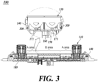
- FIG. 3 is a cross-sectional view taken along line A-A of FIG. 1 .
- the transmission member 151 includes an engaging portion 300 so that the light guide member 150 may be fixed to the front panel 140.
- the engaging portion 300 is formed at the rear of the transmission member 151.
- the light guide member 150 may be coupled to an accommodating space of the front panel 140 based on the engaging portion 300 of the transmission member 151.
- the non-illuminated area (B area) in which the shielding member 152 is formed shields light emitted from the illuminated area (A area). In other words, the non-illuminated area (B area) may prevent light leakage from light generated in the illuminated area (A area).
- a shape and area of the transmission member 151 and the shielding member 152 of the light guide member 150 are not limited thereto. This is only an embodiment, and the light guide member 150 may be disposed in any area of the vehicle in which the illuminated area and the non-illumination area should be separated. For example, the light guide member 150 may be disposed in one or more places inside the vehicle, such as a center console, cockpit, or door.
- the size of the illuminated area may be, for example, 1 mm in vertical length and 40 mm in horizontal length. However, this is only an embodiment, and the size of the illuminated area is not limited thereto. The size of the illuminated area may be determined based on, for example, vehicle specifications and an installation position of the light guide member 150.
- the shielding member 152 may be injection-molded based on, for example, any one of acrylonitrile butadiene styrene (ABS), polyvinyl chloride (PVC), and polyurethane (PU).
- ABS acrylonitrile butadiene styrene
- PVC polyvinyl chloride
- PU polyurethane
- the shielding member 152 may be manufactured using a black material in order to shield light emitted from the plurality of lighting sources 171.
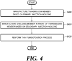
- FIG. 4 is a flowchart illustrating a method of manufacturing a lighting apparatus for a vehicle according to an embodiment of the present disclosure.
- the transmission member 151 is manufactured based on primary injection molding (S400).
- the transmission member 151 may be injection-molded using a transparent material.
- the shielding member 152 is manufactured in front of the transmission member 151 based on secondary injection molding (S410). Based on double-injection molding, the shielding member 152 may be injection-molded in front of the transmission member 151. The shielding member 152 may be inj ection-molded using a black material to prevent light from transmitting.
- a thin film deposition process is performed (S420). After the transmission member 151 and the shielding member 152 are manufactured based on double- injection molding, the thin film deposition process may be performed on the shielding member 152.
- the shielding member 152 is disposed to be exposed to the front between the plurality of first buttons 120 and the plurality of second buttons 130. Accordingly, a chromium metal may be deposited on the shielding member 152 so that the glossy surface formed of a metal material is expressed during the day, and the illuminated area and the non-illuminated area may be distinguished from each other at night.
- the thin film deposition process according to an embodiment of the present disclosure may include a physical vapor deposition (PVD) process.
- PVD physical vapor deposition
Landscapes
- Engineering & Computer Science (AREA)
- Mechanical Engineering (AREA)
- Physics & Mathematics (AREA)
- Chemical & Material Sciences (AREA)
- General Physics & Mathematics (AREA)
- Manufacturing & Machinery (AREA)
- Optics & Photonics (AREA)
- Combustion & Propulsion (AREA)
- Transportation (AREA)
- Theoretical Computer Science (AREA)
- Chemical Kinetics & Catalysis (AREA)
- Materials Engineering (AREA)
- Metallurgy (AREA)
- Organic Chemistry (AREA)
- Arrangements Of Lighting Devices For Vehicle Interiors, Mounting And Supporting Thereof, Circuits Therefore (AREA)
Abstract
A lighting apparatus for a vehicle, the lighting apparatus including: a rear panel; a printed circuit board (PCB) disposed in front of the rear panel and including a plurality of lighting sources; a rubber pad disposed in front of the PCB and configured to a plurality of through-holes formed based on positions of the plurality of lighting sources; a front panel snap-fitted to the rear panel; and a light guide member coupled to an accommodating space formed between a plurality of first buttons and a plurality of second buttons disposed on the front panel, wherein the light guide member includes a transmission member through which light emitted from the plurality of lighting sources transmits and a shielding member shielding the light.
Description
- The present application claims the benefit under 35 USC § 119(a) of Patent Application No.
10-2023-0117673, filed on September 05, 2023, in Korea - The present disclosure relates to a lighting apparatus for a vehicle and a manufacturing method thereof.
- The content described in this section simply provides background information for the present disclosure and does not constitute prior art.
- Additionally, various terms such as first, second, A, B, (a), (b), etc., are used solely to differentiate one component from the other but not to imply or suggest the substances, order, or sequence of the components. Throughout this specification, when a part 'includes' or 'comprises' a component, the part is meant to further include other components, not to exclude thereof unless specifically stated to the contrary. The terms such as 'unit', 'module', and the like refer to one or more units for processing at least one function or operation, which may be implemented by hardware, software, or a combination thereof.
- To improve the interior emotional quality of a vehicle, plating or metal deposition is applied to decoration parts. For example, in the case of plating a decoration part, a glossy surface of a metal may be expressed during the day, while light does not pass through the decoration part at night. When metal is deposited on a decoration part, the decoration part expresses a glossy surface of the metal during the day and allows light to pass through the decoration part at night.
- However, a decoration part that requires night lighting has structural limitations in that the decoration part emit light as a whole. Therefore, if a design that requires lighting only in a partial area of the decoration part is required, the design cannot be implemented.
- In view of the above, the present disclosure provides a lighting apparatus for a vehicle, capable of implementing partial illumination in a partial section of a decoration part that requires night lighting.
- The present disclosure also provides a lighting apparatus for a vehicle, capable of expressing a glossy surface of metal during the day and illuminating only a partial area at night.
- The present disclosure also provides a lighting apparatus for a vehicle, capable of reducing the number of parts and manufacturing costs by using double-injection molding.
- The present disclosure also provides a lighting apparatus for a vehicle, which may be located in various positions inside a vehicle to increase emotional quality of the interior.
- The problems to be solved by the present disclosure are not limited to the problems mentioned above, and other problems not mentioned may be clearly understood by those skilled in the art from the description below.
- According to an embodiment, the lighting apparatus for a vehicle may implement partial illumination in a partial section of a decoration part that requires night lighting.
- According to an embodiment, the lighting apparatus for a vehicle may express a glossy surface of metal during the day and illuminate only a partial area at night.
- According to an embodiment, the lighting apparatus for a vehicle may reduce the number of parts and manufacturing costs by using double-injection molding.
- According to an embodiment, the lighting apparatus for a vehicle may be located in various positions inside a vehicle to increase emotional quality of the interior.
-
-
FIG. 1 is a perspective view schematically illustrating a configuration of a lighting apparatus for a vehicle according to an embodiment of the present disclosure. -
FIG. 2 is an exploded perspective view illustrating a configuration of a lighting apparatus for a vehicle according to an embodiment of the present disclosure. -
FIG. 3 is a cross-sectional view taken along line A-A ofFIG. 1 . -
FIG. 4 is a flowchart illustrating a method of manufacturing a lighting apparatus for a vehicle according to an embodiment of the present disclosure. - The description of the present disclosure to be disclosed below along with the accompanying drawings is intended to illustrate embodiments of the present disclosure and is not intended to represent the only embodiment in which the present disclosure may be practiced.
-
FIG. 1 is a perspective view schematically illustrating a configuration of a lighting apparatus for a vehicle according to an embodiment of the present disclosure. -
FIG. 2 is an exploded perspective view illustrating a configuration of a lighting apparatus for a vehicle according to an embodiment of the present disclosure. - Referring to
FIGS. 1 and2 , a lighting apparatus for a vehicle includes some or all of afront panel 140, alight guide member 150, arubber pad 160, a printed circuit board (PCB) 170, and arear panel 180. - The
front panel 140 includes a plurality offirst buttons 120 and a plurality ofsecond buttons 130. The plurality offirst buttons 120 may be push buttons. The plurality offirst buttons 120 are aligned and arranged in a longitudinal direction of thefront panel 140. The plurality ofsecond buttons 130 are aligned and arranged at the bottom of the plurality of alignedfirst buttons 120. Here, the plurality ofsecond buttons 130 may be toggle buttons. -
Button knobs 110 are disposed on both ends of thefront panel 140. Thebutton knob 110 may be clicked by a user to be turned on/off. Thebutton knob 110 may be rotated by the user to adjust the volume of media, etc. - The
light guide member 150 according to an embodiment of the present disclosure is disposed between the plurality offirst buttons 120 and the plurality ofsecond buttons 130. Thelight guide member 150 has a predetermined size and thickness to be disposed in a local area. - The
light guide member 150 includes atransmission member 151 and ashielding member 152. - The
light guide member 150 is manufactured based on double injection molding. For example, thetransmission member 151 is injection-molded based on primary injection molding to be manufactured. Theshielding member 152 is injection-molded in front of thetransmission member 151 based on secondary injection molding to be manufactured. - The
light guide member 150 is manufactured based on double injection molding, and then metal formed of chrome is deposited based on a thin film processing process. Here, the thin film processing process includes a physical vapor deposition (PVD) process. - The PCB 170 includes a plurality of
lighting sources 171. Here, the plurality oflighting sources 171 may be light emitting diodes (LEDs). Here, the plurality oflighting sources 171 are arranged on an upper surface of thePCB 170. A plurality oflighting sources 171 may be arranged on the upper surface of thePCB 170 based on a predetermined pattern. - The
transmission member 151 may be injection-molded based on the shape of an injection mold. Thetransmission member 151 according to an embodiment of the present disclosure may have a shape with a predetermined thickness so that thetransmission member 151 may be disposed between the plurality offirst buttons 120 and the plurality ofsecond buttons 130. Thetransmission member 151 may transmit light emitted from the plurality oflighting sources 171 to the front. - The
shielding member 152 shields light transmitted from thetransmission member 151 to form an illuminated area and a non-illuminated area of thelight guide member 150. Accordingly, theshielding member 152 has a shape corresponding to a front area of thetransmission member 151. Theshielding member 152 is manufactured in a shape in which a partial area is open so that a portion of light passing through thetransmission member 151 may be irradiated forwardly. - When the
light guide member 150 is disposed between the plurality offirst buttons 120 and the plurality ofsecond buttons 130, theshielding member 152 is coupled in a state exposed to the front. Accordingly, a thin film formed of metal may be deposited on theshielding member 152 to have a glossy surface during the day. A thin film formed of, for example, chrome, is formed on theshielding member 152 according to an embodiment of the present disclosure. However, the material deposited on theshielding member 152 is not limited thereto. - The
rubber pad 160 is disposed in front of thePCB 170. Therubber pad 160 includes a through-hole (not shown). The through-hole of therubber pad 160 is formed based on the position of each of the plurality oflighting sources 171 arranged on thePCB 170. - The
rubber pad 160 may dissipate heat generated by the plurality oflighting sources 171. -
FIG. 3 is a cross-sectional view taken along line A-A ofFIG. 1 . - Referring to
FIGS. 2 and3 , thelight guide member 150 has an illuminated area (A area) and a non-illuminated area (B area). Thelight guide member 150 may be coupled between the button knobs 110 disposed at both ends. - The
transmission member 151 includes an engagingportion 300 so that thelight guide member 150 may be fixed to thefront panel 140. The engagingportion 300 is formed at the rear of thetransmission member 151. There may be a plurality of engagingportions 300 having a hook shape. Thelight guide member 150 may be coupled to an accommodating space of thefront panel 140 based on the engagingportion 300 of thetransmission member 151. - Light emitted from the plurality of
lighting sources 171 is emitted to the front of thefront panel 140 via thetransmission member 151. Here, the non-illuminated area (B area) in which the shieldingmember 152 is formed shields light emitted from the illuminated area (A area). In other words, the non-illuminated area (B area) may prevent light leakage from light generated in the illuminated area (A area). - A shape and area of the
transmission member 151 and the shieldingmember 152 of thelight guide member 150 are not limited thereto. This is only an embodiment, and thelight guide member 150 may be disposed in any area of the vehicle in which the illuminated area and the non-illumination area should be separated. For example, thelight guide member 150 may be disposed in one or more places inside the vehicle, such as a center console, cockpit, or door. - In order to emit light from the plurality of
lighting sources 171 arranged in front of thePCB 170 to the front, thetransmission member 151 is injection-molded based on a highly transmissive polycarbonate material to be manufactured. However, the material of thetransmission member 151 is not limited thereto. For example, the transmission member may be injection-molded using any one of acrylic (PMMA), polyethylene terephthalate (PET), polypropylene (PP), polyurethane (PU), and silicone. - The shielding
member 152 may shield a partial area of thelight guide member 150. The shieldingmember 152 may be injection-molded in a partially open shape during the secondary injection molding. The open shape of the shieldingmember 152 forms an optical path so that light emitted from the plurality oflighting sources 171 may pass through thetransmission member 151 and then be projected forwardly. - The size of the illuminated area according to an embodiment of the present disclosure may be, for example, 1 mm in vertical length and 40 mm in horizontal length. However, this is only an embodiment, and the size of the illuminated area is not limited thereto. The size of the illuminated area may be determined based on, for example, vehicle specifications and an installation position of the
light guide member 150. - The shielding
member 152 may be injection-molded based on, for example, any one of acrylonitrile butadiene styrene (ABS), polyvinyl chloride (PVC), and polyurethane (PU). - The shielding
member 152 may be manufactured using a black material in order to shield light emitted from the plurality oflighting sources 171. -
FIG. 4 is a flowchart illustrating a method of manufacturing a lighting apparatus for a vehicle according to an embodiment of the present disclosure. - Referring to
FIGS. 1 and4 , thetransmission member 151 is manufactured based on primary injection molding (S400). Thetransmission member 151 may be injection-molded using a transparent material. - The shielding
member 152 is manufactured in front of thetransmission member 151 based on secondary injection molding (S410). Based on double-injection molding, the shieldingmember 152 may be injection-molded in front of thetransmission member 151. The shieldingmember 152 may be inj ection-molded using a black material to prevent light from transmitting. - A thin film deposition process is performed (S420). After the
transmission member 151 and the shieldingmember 152 are manufactured based on double- injection molding, the thin film deposition process may be performed on the shieldingmember 152. The shieldingmember 152 is disposed to be exposed to the front between the plurality offirst buttons 120 and the plurality ofsecond buttons 130. Accordingly, a chromium metal may be deposited on the shieldingmember 152 so that the glossy surface formed of a metal material is expressed during the day, and the illuminated area and the non-illuminated area may be distinguished from each other at night. The thin film deposition process according to an embodiment of the present disclosure may include a physical vapor deposition (PVD) process. - Although exemplary embodiments of the present disclosure have been described for illustrative purposes, those skilled in the art will appreciate that various modifications, additions, and substitutions are possible, without departing from the idea and scope of the claimed invention. Therefore, exemplary embodiments of the present disclosure have been described for the sake of brevity and clarity. The scope of the technical idea of the present embodiments is not limited by the illustrations. Accordingly, one of ordinary skill would understand that the scope of the claimed invention is not to be limited by the above explicitly described embodiments but by the claims and equivalents thereof.
Claims (12)
- A lighting apparatus for a vehicle, the lighting apparatus comprising:a rear panel;a printed circuit board (PCB) disposed in front of the rear panel and including a plurality of lighting sources;a rubber pad disposed in front of the PCB and having a plurality of through-holes arranged based on positions of the plurality of lighting sources;a front panel snap-fitted to the rear panel; anda light guide member coupled to an accommodating space between a plurality of first buttons and a plurality of second buttons disposed on the front panel,wherein the light guide member includes a transmission member through which light emitted from the plurality of lighting sources transmits and a shielding member shielding the light.
- The lighting apparatus of claim 1, wherein
the light guide member is manufactured using double-injection molding. - The lighting apparatus of claim 1 or 2, wherein
the shielding member is configured to have an open area to expose a partial area of the transmission member to the front. - The lighting apparatus of any one of claims 1 to 3, wherein
the transmission member includes a material that transmits the light emitted from the plurality of lighting sources. - The lighting apparatus of claim 4, wherein
the material of the transmission member includes one of polycarbonate (PC), acrylic (PMMA), polyethylene terephthalate (PET), polypropylene (PP), polyurethane (PU), and silicone. - The lighting apparatus of any one of claims 1 to 5, wherein
the shielding member includes a material that blocks the light emitted from the plurality of lighting sources. - The lighting apparatus of claim 6, wherein
the material of the shielding member includes one of acrylonitrile butadiene styrene (ABS), polyvinyl chloride (PVC), and polyurethane (PU). - The lighting apparatus of any one of claims 1 to 7, wherein
the transmission member includes a plurality of engaging portions protruding backwardly to be coupled to the accommodating space. - The lighting apparatus of claim 8, wherein
the plurality of engaging portions have a hook shape to be snap-fitted into the accommodating space. - The lighting apparatus of any one of claims 1 to 9, further comprising:
a thin film disposed on the light guide member. - The lighting apparatus of any one of claims 8 to 10, wherein
the thin film includes chrome. - A method of manufacturing a lighting apparatus for a vehicle, the method comprising:manufacturing a transmission member based on primary injection molding;manufacturing a shielding member in front of the transmission member based on secondary injection molding; andperforming a thin film deposition process to form a thin film on the shielding member,wherein the manufacturing of the shielding member in front of the transmission member includes injection-molding the shielding member to have a partially open area so that an illuminated area and a non-illuminated area are formed on the transmission member.
Applications Claiming Priority (1)
| Application Number | Priority Date | Filing Date | Title |
|---|---|---|---|
| KR1020230117673A KR20250035257A (en) | 2023-09-05 | 2023-09-05 | Lighting Apparatus for Vehicle And Manufacturing Method Therefor |
Publications (1)
| Publication Number | Publication Date |
|---|---|
| EP4520569A1 true EP4520569A1 (en) | 2025-03-12 |
Family
ID=91617059
Family Applications (1)
| Application Number | Title | Priority Date | Filing Date |
|---|---|---|---|
| EP24183104.9A Pending EP4520569A1 (en) | 2023-09-05 | 2024-06-19 | Lighting apparatus for vehicle and manufacturing method thereof |
Country Status (4)
| Country | Link |
|---|---|
| US (1) | US12427917B2 (en) |
| EP (1) | EP4520569A1 (en) |
| KR (1) | KR20250035257A (en) |
| CN (1) | CN119580600A (en) |
Citations (3)
| Publication number | Priority date | Publication date | Assignee | Title |
|---|---|---|---|---|
| FR2957724A1 (en) * | 2010-03-19 | 2011-09-23 | Delphi Tech Inc | Illumination device for use in control knob of fascia of ventilation and air-conditioning system of motor vehicle to produce cornice lighting, has optical part designed to be back lighted by light guide so as to form cornice lighting |
| US20150362658A1 (en) * | 2014-06-17 | 2015-12-17 | Hyundai Mobis Co., Ltd. | Lighting device for button of audio-visual system |
| EP3848628A1 (en) * | 2020-01-09 | 2021-07-14 | Motherson Innovations Company Limited | A light emitting system, a design element, a rear view device, a covering device, and a body component of a vehicle |
Family Cites Families (1)
| Publication number | Priority date | Publication date | Assignee | Title |
|---|---|---|---|---|
| JP2012123372A (en) * | 2010-11-16 | 2012-06-28 | Nikon Corp | Light emitting mechanism for operation section and operation mechanism |
-
2023
- 2023-09-05 KR KR1020230117673A patent/KR20250035257A/en active Pending
-
2024
- 2024-06-13 US US18/742,289 patent/US12427917B2/en active Active
- 2024-06-19 EP EP24183104.9A patent/EP4520569A1/en active Pending
- 2024-07-04 CN CN202410893788.7A patent/CN119580600A/en active Pending
Patent Citations (3)
| Publication number | Priority date | Publication date | Assignee | Title |
|---|---|---|---|---|
| FR2957724A1 (en) * | 2010-03-19 | 2011-09-23 | Delphi Tech Inc | Illumination device for use in control knob of fascia of ventilation and air-conditioning system of motor vehicle to produce cornice lighting, has optical part designed to be back lighted by light guide so as to form cornice lighting |
| US20150362658A1 (en) * | 2014-06-17 | 2015-12-17 | Hyundai Mobis Co., Ltd. | Lighting device for button of audio-visual system |
| EP3848628A1 (en) * | 2020-01-09 | 2021-07-14 | Motherson Innovations Company Limited | A light emitting system, a design element, a rear view device, a covering device, and a body component of a vehicle |
Also Published As
| Publication number | Publication date |
|---|---|
| US20250074302A1 (en) | 2025-03-06 |
| KR20250035257A (en) | 2025-03-12 |
| CN119580600A (en) | 2025-03-07 |
| US12427917B2 (en) | 2025-09-30 |
Similar Documents
| Publication | Publication Date | Title |
|---|---|---|
| US10549685B2 (en) | Soft upper trim for switch assembly of vehicle door and method of manufacturing the same | |
| US4683359A (en) | Illuminated switch assembly with combined light and light shield | |
| KR960032270A (en) | Control panel | |
| CN109883131B (en) | Refrigerator with a door | |
| US7265307B2 (en) | Illumination push switch unit | |
| US5703625A (en) | Illuminated push button display | |
| EP4520569A1 (en) | Lighting apparatus for vehicle and manufacturing method thereof | |
| JP7274531B2 (en) | KEYBOARD DEVICE, ELECTRONIC DEVICE, AND METHOD OF MANUFACTURING KEYBOARD DEVICE | |
| JP4426952B2 (en) | Illuminated slide switch device | |
| US7598926B2 (en) | Display panel, control display panel and method for integrally molding insert material | |
| US20050264889A1 (en) | Display member and panel display unit | |
| KR102293599B1 (en) | Electronic appliance | |
| US20230099860A1 (en) | Uniform light halo for single keyboard key | |
| CN206532721U (en) | Automobile gears indicator button switch combination structure | |
| JP2017097963A (en) | Operation device | |
| EP1399907B1 (en) | Backlit logo assembly and method | |
| US11644616B1 (en) | Display cover having a window | |
| JP6925373B2 (en) | Operation unit structure and electronic devices equipped with this | |
| JP2024050116A (en) | Lighting equipment | |
| JP2009128889A (en) | Luminous display member and luminous display device | |
| EP4485434A1 (en) | Display apparatus and electronic instrument | |
| KR20060071660A (en) | Refrigerator | |
| JP2000173386A (en) | Push button device | |
| US11556186B1 (en) | Backlight control system having at least one movable light sheet that includes at least one light-emitting unit | |
| JP6628087B2 (en) | Operation device |
Legal Events
| Date | Code | Title | Description |
|---|---|---|---|
| PUAI | Public reference made under article 153(3) epc to a published international application that has entered the european phase |
Free format text: ORIGINAL CODE: 0009012 |
|
| STAA | Information on the status of an ep patent application or granted ep patent |
Free format text: STATUS: THE APPLICATION HAS BEEN PUBLISHED |
|
| AK | Designated contracting states |
Kind code of ref document: A1 Designated state(s): AL AT BE BG CH CY CZ DE DK EE ES FI FR GB GR HR HU IE IS IT LI LT LU LV MC ME MK MT NL NO PL PT RO RS SE SI SK SM TR |
|
| STAA | Information on the status of an ep patent application or granted ep patent |
Free format text: STATUS: REQUEST FOR EXAMINATION WAS MADE |
|
| 17P | Request for examination filed |
Effective date: 20250515 |