EP4520559A1 - Vehicle thermal management system and vehicle - Google Patents
Vehicle thermal management system and vehicle Download PDFInfo
- Publication number
- EP4520559A1 EP4520559A1 EP23814950.4A EP23814950A EP4520559A1 EP 4520559 A1 EP4520559 A1 EP 4520559A1 EP 23814950 A EP23814950 A EP 23814950A EP 4520559 A1 EP4520559 A1 EP 4520559A1
- Authority
- EP
- European Patent Office
- Prior art keywords
- temperature
- rotation speed
- fan
- engine
- thermal management
- Prior art date
- Legal status (The legal status is an assumption and is not a legal conclusion. Google has not performed a legal analysis and makes no representation as to the accuracy of the status listed.)
- Pending
Links
Images


Classifications
-
- B—PERFORMING OPERATIONS; TRANSPORTING
- B60—VEHICLES IN GENERAL
- B60H—ARRANGEMENTS OF HEATING, COOLING, VENTILATING OR OTHER AIR-TREATING DEVICES SPECIALLY ADAPTED FOR PASSENGER OR GOODS SPACES OF VEHICLES
- B60H1/00—Heating, cooling or ventilating devices
- B60H1/32—Cooling devices
-
- B—PERFORMING OPERATIONS; TRANSPORTING
- B60—VEHICLES IN GENERAL
- B60H—ARRANGEMENTS OF HEATING, COOLING, VENTILATING OR OTHER AIR-TREATING DEVICES SPECIALLY ADAPTED FOR PASSENGER OR GOODS SPACES OF VEHICLES
- B60H1/00—Heating, cooling or ventilating devices
- B60H1/00357—Air-conditioning arrangements specially adapted for particular vehicles
- B60H1/00385—Air-conditioning arrangements specially adapted for particular vehicles for vehicles having an electrical drive, e.g. hybrid or fuel cell
- B60H1/004—Air-conditioning arrangements specially adapted for particular vehicles for vehicles having an electrical drive, e.g. hybrid or fuel cell for vehicles having a combustion engine and electric drive means, e.g. hybrid electric vehicles
-
- B—PERFORMING OPERATIONS; TRANSPORTING
- B60—VEHICLES IN GENERAL
- B60H—ARRANGEMENTS OF HEATING, COOLING, VENTILATING OR OTHER AIR-TREATING DEVICES SPECIALLY ADAPTED FOR PASSENGER OR GOODS SPACES OF VEHICLES
- B60H1/00—Heating, cooling or ventilating devices
- B60H1/00271—HVAC devices specially adapted for particular vehicle parts or components and being connected to the vehicle HVAC unit
- B60H1/00278—HVAC devices specially adapted for particular vehicle parts or components and being connected to the vehicle HVAC unit for the battery
-
- B—PERFORMING OPERATIONS; TRANSPORTING
- B60—VEHICLES IN GENERAL
- B60K—ARRANGEMENT OR MOUNTING OF PROPULSION UNITS OR OF TRANSMISSIONS IN VEHICLES; ARRANGEMENT OR MOUNTING OF PLURAL DIVERSE PRIME-MOVERS IN VEHICLES; AUXILIARY DRIVES FOR VEHICLES; INSTRUMENTATION OR DASHBOARDS FOR VEHICLES; ARRANGEMENTS IN CONNECTION WITH COOLING, AIR INTAKE, GAS EXHAUST OR FUEL SUPPLY OF PROPULSION UNITS IN VEHICLES
- B60K11/00—Arrangement in connection with cooling of propulsion units
- B60K11/02—Arrangement in connection with cooling of propulsion units with liquid cooling
- B60K11/04—Arrangement or mounting of radiators, radiator shutters, or radiator blinds
-
- B—PERFORMING OPERATIONS; TRANSPORTING
- B60—VEHICLES IN GENERAL
- B60K—ARRANGEMENT OR MOUNTING OF PROPULSION UNITS OR OF TRANSMISSIONS IN VEHICLES; ARRANGEMENT OR MOUNTING OF PLURAL DIVERSE PRIME-MOVERS IN VEHICLES; AUXILIARY DRIVES FOR VEHICLES; INSTRUMENTATION OR DASHBOARDS FOR VEHICLES; ARRANGEMENTS IN CONNECTION WITH COOLING, AIR INTAKE, GAS EXHAUST OR FUEL SUPPLY OF PROPULSION UNITS IN VEHICLES
- B60K11/00—Arrangement in connection with cooling of propulsion units
- B60K11/06—Arrangement in connection with cooling of propulsion units with air cooling
-
- B—PERFORMING OPERATIONS; TRANSPORTING
- B60—VEHICLES IN GENERAL
- B60L—PROPULSION OF ELECTRICALLY-PROPELLED VEHICLES; SUPPLYING ELECTRIC POWER FOR AUXILIARY EQUIPMENT OF ELECTRICALLY-PROPELLED VEHICLES; ELECTRODYNAMIC BRAKE SYSTEMS FOR VEHICLES IN GENERAL; MAGNETIC SUSPENSION OR LEVITATION FOR VEHICLES; MONITORING OPERATING VARIABLES OF ELECTRICALLY-PROPELLED VEHICLES; ELECTRIC SAFETY DEVICES FOR ELECTRICALLY-PROPELLED VEHICLES
- B60L58/00—Methods or circuit arrangements for monitoring or controlling batteries or fuel cells, specially adapted for electric vehicles
- B60L58/10—Methods or circuit arrangements for monitoring or controlling batteries or fuel cells, specially adapted for electric vehicles for monitoring or controlling batteries
- B60L58/24—Methods or circuit arrangements for monitoring or controlling batteries or fuel cells, specially adapted for electric vehicles for monitoring or controlling batteries for controlling the temperature of batteries
- B60L58/26—Methods or circuit arrangements for monitoring or controlling batteries or fuel cells, specially adapted for electric vehicles for monitoring or controlling batteries for controlling the temperature of batteries by cooling
-
- F—MECHANICAL ENGINEERING; LIGHTING; HEATING; WEAPONS; BLASTING
- F01—MACHINES OR ENGINES IN GENERAL; ENGINE PLANTS IN GENERAL; STEAM ENGINES
- F01P—COOLING OF MACHINES OR ENGINES IN GENERAL; COOLING OF INTERNAL-COMBUSTION ENGINES
- F01P5/00—Pumping cooling-air or liquid coolants
- F01P5/02—Pumping cooling-air; Arrangements of cooling-air pumps, e.g. fans or blowers
-
- F—MECHANICAL ENGINEERING; LIGHTING; HEATING; WEAPONS; BLASTING
- F01—MACHINES OR ENGINES IN GENERAL; ENGINE PLANTS IN GENERAL; STEAM ENGINES
- F01P—COOLING OF MACHINES OR ENGINES IN GENERAL; COOLING OF INTERNAL-COMBUSTION ENGINES
- F01P7/00—Controlling of coolant flow
- F01P7/14—Controlling of coolant flow the coolant being liquid
- F01P7/16—Controlling of coolant flow the coolant being liquid by thermostatic control
- F01P7/164—Controlling of coolant flow the coolant being liquid by thermostatic control by varying pump speed
-
- F—MECHANICAL ENGINEERING; LIGHTING; HEATING; WEAPONS; BLASTING
- F01—MACHINES OR ENGINES IN GENERAL; ENGINE PLANTS IN GENERAL; STEAM ENGINES
- F01P—COOLING OF MACHINES OR ENGINES IN GENERAL; COOLING OF INTERNAL-COMBUSTION ENGINES
- F01P7/00—Controlling of coolant flow
- F01P7/14—Controlling of coolant flow the coolant being liquid
- F01P7/16—Controlling of coolant flow the coolant being liquid by thermostatic control
- F01P7/165—Controlling of coolant flow the coolant being liquid by thermostatic control characterised by systems with two or more loops
-
- H—ELECTRICITY
- H01—ELECTRIC ELEMENTS
- H01M—PROCESSES OR MEANS, e.g. BATTERIES, FOR THE DIRECT CONVERSION OF CHEMICAL ENERGY INTO ELECTRICAL ENERGY
- H01M10/00—Secondary cells; Manufacture thereof
- H01M10/60—Heating or cooling; Temperature control
- H01M10/61—Types of temperature control
- H01M10/613—Cooling or keeping cold
-
- H—ELECTRICITY
- H01—ELECTRIC ELEMENTS
- H01M—PROCESSES OR MEANS, e.g. BATTERIES, FOR THE DIRECT CONVERSION OF CHEMICAL ENERGY INTO ELECTRICAL ENERGY
- H01M10/00—Secondary cells; Manufacture thereof
- H01M10/60—Heating or cooling; Temperature control
- H01M10/62—Heating or cooling; Temperature control specially adapted for specific applications
- H01M10/625—Vehicles
-
- H—ELECTRICITY
- H01—ELECTRIC ELEMENTS
- H01M—PROCESSES OR MEANS, e.g. BATTERIES, FOR THE DIRECT CONVERSION OF CHEMICAL ENERGY INTO ELECTRICAL ENERGY
- H01M10/00—Secondary cells; Manufacture thereof
- H01M10/60—Heating or cooling; Temperature control
- H01M10/65—Means for temperature control structurally associated with the cells
- H01M10/655—Solid structures for heat exchange or heat conduction
- H01M10/6556—Solid parts with flow channel passages or pipes for heat exchange
-
- H—ELECTRICITY
- H01—ELECTRIC ELEMENTS
- H01M—PROCESSES OR MEANS, e.g. BATTERIES, FOR THE DIRECT CONVERSION OF CHEMICAL ENERGY INTO ELECTRICAL ENERGY
- H01M10/00—Secondary cells; Manufacture thereof
- H01M10/60—Heating or cooling; Temperature control
- H01M10/65—Means for temperature control structurally associated with the cells
- H01M10/656—Means for temperature control structurally associated with the cells characterised by the type of heat-exchange fluid
- H01M10/6567—Liquids
- H01M10/6568—Liquids characterised by flow circuits, e.g. loops, located externally to the cells or cell casings
-
- H—ELECTRICITY
- H01—ELECTRIC ELEMENTS
- H01M—PROCESSES OR MEANS, e.g. BATTERIES, FOR THE DIRECT CONVERSION OF CHEMICAL ENERGY INTO ELECTRICAL ENERGY
- H01M10/00—Secondary cells; Manufacture thereof
- H01M10/60—Heating or cooling; Temperature control
- H01M10/65—Means for temperature control structurally associated with the cells
- H01M10/656—Means for temperature control structurally associated with the cells characterised by the type of heat-exchange fluid
- H01M10/6569—Fluids undergoing a liquid-gas phase change or transition, e.g. evaporation or condensation
-
- H—ELECTRICITY
- H01—ELECTRIC ELEMENTS
- H01M—PROCESSES OR MEANS, e.g. BATTERIES, FOR THE DIRECT CONVERSION OF CHEMICAL ENERGY INTO ELECTRICAL ENERGY
- H01M10/00—Secondary cells; Manufacture thereof
- H01M10/60—Heating or cooling; Temperature control
- H01M10/66—Heat-exchange relationships between the cells and other systems, e.g. central heating systems or fuel cells
- H01M10/663—Heat-exchange relationships between the cells and other systems, e.g. central heating systems or fuel cells the system being an air-conditioner or an engine
-
- B—PERFORMING OPERATIONS; TRANSPORTING
- B60—VEHICLES IN GENERAL
- B60H—ARRANGEMENTS OF HEATING, COOLING, VENTILATING OR OTHER AIR-TREATING DEVICES SPECIALLY ADAPTED FOR PASSENGER OR GOODS SPACES OF VEHICLES
- B60H1/00—Heating, cooling or ventilating devices
- B60H1/00642—Control systems or circuits; Control members or indication devices for heating, cooling or ventilating devices
- B60H1/00814—Control systems or circuits characterised by their output, for controlling particular components of the heating, cooling or ventilating installation
- B60H1/00821—Control systems or circuits characterised by their output, for controlling particular components of the heating, cooling or ventilating installation the components being ventilating, air admitting or air distributing devices
- B60H1/00828—Ventilators, e.g. speed control
-
- B—PERFORMING OPERATIONS; TRANSPORTING
- B60—VEHICLES IN GENERAL
- B60H—ARRANGEMENTS OF HEATING, COOLING, VENTILATING OR OTHER AIR-TREATING DEVICES SPECIALLY ADAPTED FOR PASSENGER OR GOODS SPACES OF VEHICLES
- B60H1/00—Heating, cooling or ventilating devices
- B60H1/00642—Control systems or circuits; Control members or indication devices for heating, cooling or ventilating devices
- B60H1/00814—Control systems or circuits characterised by their output, for controlling particular components of the heating, cooling or ventilating installation
- B60H1/00878—Control systems or circuits characterised by their output, for controlling particular components of the heating, cooling or ventilating installation the components being temperature regulating devices
- B60H1/00885—Controlling the flow of heating or cooling liquid, e.g. valves or pumps
-
- B—PERFORMING OPERATIONS; TRANSPORTING
- B60—VEHICLES IN GENERAL
- B60H—ARRANGEMENTS OF HEATING, COOLING, VENTILATING OR OTHER AIR-TREATING DEVICES SPECIALLY ADAPTED FOR PASSENGER OR GOODS SPACES OF VEHICLES
- B60H1/00—Heating, cooling or ventilating devices
- B60H1/32—Cooling devices
- B60H1/3204—Cooling devices using compression
- B60H1/3228—Cooling devices using compression characterised by refrigerant circuit configurations
- B60H1/32281—Cooling devices using compression characterised by refrigerant circuit configurations comprising a single secondary circuit, e.g. at evaporator or condenser side
-
- B—PERFORMING OPERATIONS; TRANSPORTING
- B60—VEHICLES IN GENERAL
- B60H—ARRANGEMENTS OF HEATING, COOLING, VENTILATING OR OTHER AIR-TREATING DEVICES SPECIALLY ADAPTED FOR PASSENGER OR GOODS SPACES OF VEHICLES
- B60H1/00—Heating, cooling or ventilating devices
- B60H1/00271—HVAC devices specially adapted for particular vehicle parts or components and being connected to the vehicle HVAC unit
- B60H2001/00307—Component temperature regulation using a liquid flow
-
- B—PERFORMING OPERATIONS; TRANSPORTING
- B60—VEHICLES IN GENERAL
- B60H—ARRANGEMENTS OF HEATING, COOLING, VENTILATING OR OTHER AIR-TREATING DEVICES SPECIALLY ADAPTED FOR PASSENGER OR GOODS SPACES OF VEHICLES
- B60H1/00—Heating, cooling or ventilating devices
- B60H1/32—Cooling devices
- B60H2001/3236—Cooling devices information from a variable is obtained
- B60H2001/3255—Cooling devices information from a variable is obtained related to temperature
-
- B—PERFORMING OPERATIONS; TRANSPORTING
- B60—VEHICLES IN GENERAL
- B60H—ARRANGEMENTS OF HEATING, COOLING, VENTILATING OR OTHER AIR-TREATING DEVICES SPECIALLY ADAPTED FOR PASSENGER OR GOODS SPACES OF VEHICLES
- B60H1/00—Heating, cooling or ventilating devices
- B60H1/32—Cooling devices
- B60H2001/3269—Cooling devices output of a control signal
- B60H2001/327—Cooling devices output of a control signal related to a compressing unit
- B60H2001/3272—Cooling devices output of a control signal related to a compressing unit to control the revolving speed of a compressor
-
- F—MECHANICAL ENGINEERING; LIGHTING; HEATING; WEAPONS; BLASTING
- F01—MACHINES OR ENGINES IN GENERAL; ENGINE PLANTS IN GENERAL; STEAM ENGINES
- F01P—COOLING OF MACHINES OR ENGINES IN GENERAL; COOLING OF INTERNAL-COMBUSTION ENGINES
- F01P5/00—Pumping cooling-air or liquid coolants
- F01P5/02—Pumping cooling-air; Arrangements of cooling-air pumps, e.g. fans or blowers
- F01P2005/025—Pumping cooling-air; Arrangements of cooling-air pumps, e.g. fans or blowers using two or more air pumps
-
- F—MECHANICAL ENGINEERING; LIGHTING; HEATING; WEAPONS; BLASTING
- F01—MACHINES OR ENGINES IN GENERAL; ENGINE PLANTS IN GENERAL; STEAM ENGINES
- F01P—COOLING OF MACHINES OR ENGINES IN GENERAL; COOLING OF INTERNAL-COMBUSTION ENGINES
- F01P7/00—Controlling of coolant flow
- F01P7/14—Controlling of coolant flow the coolant being liquid
- F01P2007/146—Controlling of coolant flow the coolant being liquid using valves
-
- F—MECHANICAL ENGINEERING; LIGHTING; HEATING; WEAPONS; BLASTING
- F01—MACHINES OR ENGINES IN GENERAL; ENGINE PLANTS IN GENERAL; STEAM ENGINES
- F01P—COOLING OF MACHINES OR ENGINES IN GENERAL; COOLING OF INTERNAL-COMBUSTION ENGINES
- F01P2025/00—Measuring
- F01P2025/08—Temperature
- F01P2025/12—Cabin temperature
-
- F—MECHANICAL ENGINEERING; LIGHTING; HEATING; WEAPONS; BLASTING
- F01—MACHINES OR ENGINES IN GENERAL; ENGINE PLANTS IN GENERAL; STEAM ENGINES
- F01P—COOLING OF MACHINES OR ENGINES IN GENERAL; COOLING OF INTERNAL-COMBUSTION ENGINES
- F01P2025/00—Measuring
- F01P2025/08—Temperature
- F01P2025/32—Engine outcoming fluid temperature
-
- F—MECHANICAL ENGINEERING; LIGHTING; HEATING; WEAPONS; BLASTING
- F01—MACHINES OR ENGINES IN GENERAL; ENGINE PLANTS IN GENERAL; STEAM ENGINES
- F01P—COOLING OF MACHINES OR ENGINES IN GENERAL; COOLING OF INTERNAL-COMBUSTION ENGINES
- F01P2050/00—Applications
- F01P2050/24—Hybrid vehicles
-
- F—MECHANICAL ENGINEERING; LIGHTING; HEATING; WEAPONS; BLASTING
- F01—MACHINES OR ENGINES IN GENERAL; ENGINE PLANTS IN GENERAL; STEAM ENGINES
- F01P—COOLING OF MACHINES OR ENGINES IN GENERAL; COOLING OF INTERNAL-COMBUSTION ENGINES
- F01P2060/00—Cooling circuits using auxiliaries
- F01P2060/02—Intercooler
Definitions
- the present disclosure relates to the technical field of thermal management systems of vehicles, and in particular, to a thermal management system of a vehicle, and a vehicle.
- a radiator of a hybrid vehicle generally includes an intercooler for cooling an intake air of an engine, a high-temperature radiator for cooling a coolant in the engine, a low-temperature radiator for cooling an electric control distribution box of a motor, and a condenser for cooling an air conditioning system.
- the electronic fan In the related art, there is only one electronic fan in the hybrid vehicle, and control of a rotation speed of the electronic fan needs to meet cooling requirements of the intercooler, the high-temperature radiator, the low-temperature radiator, and the condenser simultaneously. To avoid overheating of components, the rotation speed of the electronic fan meets a largest rotation speed requirement of the intercooler, the high-temperature radiator, the low-temperature radiator, and the condenser. Therefore, the electronic fan has technical problems of high energy consumption and a poor heat dissipation effect.
- the present disclosure is intended to resolve at least one of the technical problems existing in the related art. Therefore, the present disclosure provides a thermal management system of a vehicle. During running, temperatures of a first radiator and an intercooler are close, and temperatures of a second radiator and a condenser are close. Therefore, a first fan and a second fan are used to dissipate heat, and rotation speeds of the first fan and the second fan are controlled more accurately.
- the present disclosure further provides a vehicle.
- the thermal management system includes: an engine cooling system, the engine cooling system includes: an engine, the engine includes an intake manifold and a supercharger, an intercooler, an air outlet end of the intercooler is in communication with the intake manifold, and an air inlet end of the intercooler is in communication with the supercharger, a first radiator, the first radiator is connected to the engine, and a first fan, the first fan is configured to dissipate heat from the intercooler and the first radiator; an air conditioning system, the air conditioning system includes a condenser; and a low-temperature cooling system, the low-temperature cooling system includes: a second radiator, and a second fan, the second fan is configured to dissipate heat from the second radiator and the condenser.
- temperatures of the first radiator and the intercooler are close during operating. Therefore, when the first fan is used to perform a heat dissipation operation, a rotation speed of the first fan is controlled more accurately.
- temperatures of the second radiator and the condenser are close during operating. Therefore, when the second fan is used to perform a heat dissipation operation, a rotation speed of the second fan is controlled more accurately.
- the thermal management system further includes a controller.
- the controller is configured to control running of the engine cooling system according to a temperature of a coolant of the engine.
- the engine cooling system further includes: an electronic thermostat, the electronic thermostat is arranged between a first end of the engine and a third end of the first radiator; and a first water pump, the first water pump is arranged between a second end of the engine and a fourth end of the first radiator.
- the controller is configured to adjust a rotation speed of the first water pump and an opening degree of the electronic thermostat according to the temperature of the coolant of the engine.
- the engine cooling system further includes a first temperature sensor.
- the first temperature sensor is arranged between the first radiator and the engine, and the first temperature sensor is configured to detect the temperature of the coolant of the engine.
- the controller is configured to adjust a rotation speed of the first fan according to the temperature of the coolant of the engine.
- the controller is configured to: first adjust a rotation speed of the first water pump and an opening degree of the electronic thermostat according to the temperature of the coolant, and then adjust the rotation speed of the first fan according to the temperature of the coolant.
- the thermal management system further includes: a controller.
- the controller is configured to control running of the low-temperature cooling system according to a temperature of a coolant.
- the low-temperature cooling system is formed with a first branch and a second branch arranged in parallel.
- the low-temperature cooling system further includes: a second water pump; a second temperature sensor, the second temperature sensor is connected in series with the second water pump and the second radiator; a drive motor, the drive motor is connected to the first branch; and a motor controller.
- the motor controller is electrically connected to the drive motor, and the motor controller is connected to the second branch.
- the controller is configured to adjust a rotation speed of the second water pump and a rotation speed of the second fan according to the temperature of the coolant.
- the low-temperature cooling system further includes: a generator, the generator is electrically connected to the motor controller, and the generator is connected in series with the motor controller on the second branch; and a direct current distributor.
- the direct current distributor is electrically connected to the motor controller, and the direct current distributor is connected in series with the drive motor on the first branch.
- the thermal management system further includes an expansion kettle.
- the expansion kettle is provided with a water inlet and a water outlet, the water outlet is connected to a liquid inlet of the second water pump, and the water inlet is in communication with the second radiator.
- the air conditioning system includes: a compressor, an evaporator, and a first control valve.
- the first control valve is connected in series with the compressor, the evaporator, and the condenser.
- the air conditioning system further includes: a second control valve, and a heat exchanger.
- the heat exchanger and the second control valve are arranged in series, the heat exchanger and the second control valve are arranged in parallel with the evaporator, and the heat exchanger is adapted to exchange heat with a battery pack.
- the thermal management system further includes a controller.
- the controller is configured to control switching of the first control valve and the second control valve according to a temperature of the battery pack and a temperature of a passenger compartment, and the controller is configured to adjust a rotation speed of the compressor and the rotation speed of the second fan.
- a vehicle according to an embodiment of a second aspect of the present disclosure is provided.
- the vehicle includes a thermal management system of the vehicle.
- a thermal management system 100 of a vehicle 200 is described below with reference to FIG. 1 to FIG. 5 , FIG. 7 , and FIG. 8 .
- the present disclosure further provides a vehicle 200 having the foregoing thermal management system 100.
- the thermal management system 100 of the vehicle 200 in this embodiment of the present disclosure includes an engine cooling system 10, a low-temperature cooling system 20, and an air conditioning system 30.
- the engine cooling system 10 includes an engine 11, an intercooler 12, a first radiator 15, and a first fan 13.
- the engine includes an intake manifold 111 and a supercharger 112.
- An air outlet end 121 of the intercooler 12 is in communication with the intake manifold 111, and an air inlet end 122 of the intercooler 12 is in communication with the supercharger 112.
- the engine 11 and the first radiator 15 are connected in series with each other.
- the first fan 13 is configured to dissipate heat from the intercooler 12 and the first radiator 15.
- the engine 11 and the first radiator 15 are arranged in series, so that heat generated during operating of the engine 11 can be carried away by a coolant and dissipated to the outside world through the first radiator 15.
- the first fan 13 and the first radiator 15 are arranged oppositely, and the first fan 13 faces the first radiator 15. Therefore, the first fan 13 can deliver air to the first radiator 15 to reduce the temperature of the coolant in the first radiator 15, thereby reducing the temperature of the engine cooling system 10.
- the intercooler 12 can reduce the temperature of a high-temperature gas, thereby reducing an intake air temperature of the engine 11.
- the intercooler 12 and the first radiator 15 are arranged oppositely, and the first fan 13 and the first radiator 15 are arranged oppositely.
- the first fan 13 can dissipate heat from both the first radiator 15 and the intercooler 12, so that an integration degree of the thermal management system 100 can be improved.
- a location where an air-cooled condenser 33 is originally arranged may be left free, which is conducive to optimizing space of a compartment of the engine 11.
- the temperature of the intercooler 12 is close to the temperature of the first radiator 15, and the influence on each other is small, which is conducive to increasing the service life of the intercooler 12 and the first radiator 15.
- the low-temperature cooling system 20 includes a second radiator 22 and a second fan 24.
- the second fan 24 is arranged on a side of the second radiator 22.
- the air conditioning system 30 includes the condenser 33.
- the second radiator 22 and the condenser 33 are arranged oppositely.
- the second fan 24 is configured to dissipate heat from the second radiator 22 and the condenser 33.
- the second radiator 22 of the low-temperature cooling system 20 and the condenser 33 of the air conditioning system 30 are arranged oppositely, and the second fan 24 and the second radiator 22 are arranged oppositely. Therefore, the first fan 13 can dissipate heat from both the second radiator 22 and the condenser 33, so that the integration degree of the thermal management system 100 can be improved.
- the temperature of the condenser 33 is close to the temperature of the second radiator 22, and the influence on each other is small, which is conducive to increasing the service life of the intercooler 12 and the first radiator 15.
- the thermal management system 100 has the first fan 13 and the second fan 24.
- the first fan 13 and the second fan 24 are independently controlled.
- a rotation speed of the first fan 13 only needs to meet a cooling requirement of the intercooler 12 and the first radiator 15, and a rotation speed of the second fan 24 only needs to meet a cooling requirement of the second radiator 22 and the condenser 33, which is conducive to accurate control of thermal management of the whole vehicle.
- the intercooler 12 and the first radiator 15 share the first fan 13, and the second radiator 22 and the condenser 33 share the second fan 24. Therefore, temperature interference between the intercooler 12 and the first radiator 15 is low, and temperature interference between the second radiator 22 and the condenser 33 is also low.
- the thermal management system 100 further includes a controller 40.
- the controller 40 is configured to control running of the engine cooling system 10 according to a temperature of a coolant of the engine 11. Therefore, normal use of the engine cooling system 10 is facilitated.
- the engine cooling system 10 further includes a first water pump 14 and an electronic thermostat 17.
- the electronic thermostat 17 is arranged between a first end 113 of the engine 11 and a third end 151 of the first radiator 15.
- the first water pump 14 is arranged between a second end 114 of the engine 11 and a fourth end 152 of the first radiator 15.
- the first water pump 14 can drive the coolant to circulate among the engine 11, the first water pump 14, and the first radiator 15. When the coolant flows through the engine 11, the coolant can reduce the temperature of the engine 11. When the coolant flows through the first radiator 15, the first radiator 15 can dissipate heat from the coolant.
- the electronic thermostat 17 can automatically adjust the amount of water entering the first radiator 15 according to the temperature of the cooling water, thereby changing the circulation range of the water, to adjust the heat dissipation capability of the first radiator 15, and ensure that the engine 11 operates in a suitable temperature range.
- the electronic thermostat 17 needs to maintain a good technical state; otherwise, normal operating of the engine 11 is severely affected. For example, if a main valve of the electronic thermostat 17 opens too late, the engine 11 is overheated. If the main valve opens too early, a warm-up time of the engine 11 is extended, and the temperature of the engine 11 is excessively low.
- the controller 40 is configured to adjust a rotation speed of the first water pump 14 and an opening degree of the electronic thermostat 17 according to the temperature of the coolant.
- the electronic thermostat 17 can control the flow of the coolant flowing through the electronic thermostat 17, and the first water pump 14 can control a flow rate of the coolant. That is to say, by controlling the temperature of the coolant and the flow of the coolant, the engine 11 can be rapidly cooled.
- the engine cooling system 10 further includes a first temperature sensor 16.
- the first temperature sensor 16 is arranged between the first radiator 15 and the engine 11.
- the first temperature sensor 16 is configured to detect the temperature of the coolant of the engine 11.
- the controller 40 is configured to adjust a rotation speed of the first fan 13 according to the temperature of the coolant. Therefore, when the engine cooling system 10 is running, the controller 40 can adjust the rotation speed of the first fan 13 according to the temperature of the coolant detected by the first temperature sensor 16. That is to say, by properly controlling the rotation speed of the first fan 13, the temperature of the coolant in the engine cooling system 10 can be controlled, so that the rotation speed of the first fan 13 can be controlled according to a running state of the engine 11.
- the rotation speed of the engine 11 increases, the engine 11 dissipates more heat to the outside world, and the temperature of the coolant also increases correspondingly.
- the rotation speed of the first fan 13 can be controlled by the controller 40, to control the temperature of the coolant, so that the temperature of the engine 11 is equalized or the temperature of the engine 11 is quickly reduced.
- the controller 40 is configured to: first adjust a rotation speed of the first water pump 14 and an opening degree of the electronic thermostat 17 according to the temperature of the coolant, and then adjust the rotation speed of the first fan 13 according to the temperature of the coolant. Specifically, the controller 40 may first control the opening degree of the electronic thermostat 17, and then the controller 40 controls the flow rate of the first water pump 14. Further, the controller 40 controls the rotation speed of the first fan 13. That is to say, the controller 40 preferentially controls a low-power actuator. Only when the low-power actuator does not meet the cooling requirement, the controller 40 adjusts a high-power actuator. Therefore, the energy consumption of the thermal management system 100 can be effectively reduced.
- the thermal management system 100 further includes a controller 40.
- the controller 40 is configured to control running of the low-temperature cooling system 20 according to a temperature of a coolant. Therefore, normal running of the engine cooling system 10 and the low-temperature cooling system 20 may be adjusted and controlled by the controller 40.
- the low-temperature cooling system 20 further includes a second water pump 23, a second temperature sensor 28, a drive motor, and a motor controller 25.
- the low-temperature cooling system 20 is formed with a first branch and a second branch arranged in parallel.
- the second water pump 23, the second temperature sensor 28, and the second radiator 22 are connected in series with each other.
- the motor controller 25 is electrically connected to the drive motor 21.
- the drive motor 21 is connected to the first branch.
- the motor controller 25 is connected to the second branch.
- the second water pump 23 may drive the coolant to circulate among the driving motor 21, the motor controller 25, and the second radiator 22.
- the coolant may reduce the temperature of the drive motor 21 and the temperature of the motor controller 25.
- the second radiator 22 can dissipate heat from the coolant.
- the motor controller 25 is configured to control running parameters of the drive motor 21.
- the low-temperature cooling system 20 is formed with the first branch and the second branch, and the second branch and the first branch are arranged in parallel with each other. Therefore, the motor controller 25, the drive motor 21, and the second radiator 22 are connected in parallel with each other, so that interference among the motor controller 25, the drive motor 21, and the second radiator 22 is reduced.
- the thermal management system 100 further includes a controller 40.
- the controller 40 is configured to adjust a rotation speed of the second water pump 23 and a rotation speed of the second fan 24 according to the temperature of the coolant.
- the controller 40 may adjust the rotation speeds of the second water pump 23 and the second fan 24 according to the temperature of the coolant detected by the second temperature sensor 28. That is to say, the controller 40 preferentially controls the low-power actuator.
- the controller 40 adjusts the high-power actuator, so that the energy consumption of the thermal management system 100 can be effectively reduced.
- the low-temperature cooling system 20 further includes a generator 26 and a direct current distributor 27.
- the generator 26 and the direct current distributor 27 are both electrically connected to the motor controller 25.
- the direct current distributor 27 is connected in series with the drive motor 21 on the first branch.
- the generator 26 is connected in series with the motor controller 25 on the second branch.
- the generator 26 and the direct current distributor 27 are not in a normally open state.
- the low-temperature cooling system 20 further includes an expansion kettle 36.
- the expansion kettle 36 is provided with a water inlet 361 and a water outlet 362, the water outlet 362 is connected to a liquid inlet 231 of the second water pump 23, and the water inlet 361 is connected to the second radiator 22.
- the coolant in the low-temperature cooling system 20 is insufficient.
- the coolant is injected into the low-temperature cooling system 20 through the expansion kettle 36, so that a heat exchange requirement of the low-temperature cooling system 20 can be satisfied.
- the air conditioning system 30 includes a compressor 31, an evaporator 32, a condenser 33, and a first control valve 34.
- the compressor 31, the evaporator 32, the condenser 33, and the first control valve 34 are connected in series with each other.
- the condenser 33 and the second radiator 22 are arranged oppositely.
- a high-temperature and high-pressure cooling medium compressed by the compressor 21 enters the condenser 22 and is condensed to become a medium-temperature and medium-pressure liquid cooling medium.
- the medium-temperature and medium-pressure liquid cooling medium is throttled and depressurized through a throttling element to become a low-temperature and low-pressure liquid cooling medium.
- the low-temperature and low-pressure liquid cooling medium enters the evaporator 24 to cool the air in the passenger compartment.
- the air conditioning system 30 further includes a second control valve 35 and a heat exchanger 38.
- the heat exchanger 38 and the second control valve 35 are arranged in series, the heat exchanger 38 and the second control valve 35 are arranged in parallel with the evaporator 32, and the heat exchanger 38 is adapted to exchange heat with a battery pack 201.
- the air conditioning system 30 may further exchange heat with the battery pack 201 through the heat exchanger 38. Therefore, the air conditioning system 30 can reduce the temperature of the battery pack 201.
- the air conditioning system 30 further includes a pressure sensor 37.
- the pressure sensor 37 is arranged between the compressor 31 and the condenser 33.
- the pressure sensor 37 may be configured to detect a pressure of the coolant.
- the thermal management system 100 further includes a controller 40.
- the controller 40 is configured to control switching of the first control valve 34 and the second control valve 35 according to a temperature of the battery pack 201 and a temperature of a passenger compartment, and the controller 40 is configured to adjust a rotation speed of the compressor 31 and the rotation speed of the second fan 24.
- the heat exchanger 38 and the evaporator 32 are arranged in parallel
- the evaporator 32 and the first control valve 34 are arranged in series
- the heat exchanger 38 and the second control valve 35 are arranged in series. Therefore, when the passenger compartment and the battery pack 201 have a temperature reduction need, switching of the first control valve 34 and the second control valve 35 may be selectively controlled.
- the first control valve 34 is opened, and the coolant may pass through the first control valve 34 and then exchange heat at the evaporator 32, thereby reducing the temperature of the passenger compartment.
- the second control valve 35 is opened, and the coolant may pass through the second control valve 35 and then exchange heat with the battery pack 201 at the heat exchanger 38, thereby reducing the temperature of the battery pack 201.
- the controller 40 may further control the rotation speed of the compressor 31 and the rotation speed of the second fan 24 according to the temperature of the battery pack 201 and the temperature of the passenger compartment. In other words, when there is a large difference between an actual temperature of the battery pack 201 and a preset temperature of the battery pack 201, the controller 40 may perform control to increase the rotation speed of the compressor 31 and the rotation speed of the second fan 24. Therefore, the temperature of the coolant outputted by the compressor 31 is lower, the temperature reduction of the battery pack 201 is facilitated, and the second fan 24 can quickly dissipate heat from the condenser 33.
- the controller 40 may perform control to increase the rotation speed of the compressor 31 and the rotation speed of the second fan 24, so that the temperature of the coolant outputted by the compressor 31 is lower, the temperature reduction of the battery pack 201 is facilitated, and the second fan 24 can quickly dissipate heat from the condenser 33.
- a control method for the thermal management system 100 includes the following steps: The engine 11 is started. A cooling water temperature of the engine 11 is T, a rotation speed of the first water pump 14 is C, and a rotation speed of the first fan 13 is B. A relationship between the cooling water temperature T and a predetermined value T1 is determined as follows: When T > T1, a rotation speed of the first water pump 14 is C1, a rotation speed of the first fan 13 is B1, and an opening degree of the electronic thermostat 17 is increased. In other words, when the cooling water temperature T is greater than the predetermined value T1, the rotation speed of the first water pump 14 is fixed at C1, and the rotation speed of the first fan 13 is fixed at B1. Then, by increasing the opening degree of the electronic thermostat 17, the flow of the coolant passing through the engine 11 can be increased, so that the temperature of the engine 11 can be effectively reduced.
- the first fan 13 maintains the rotation speed B1
- the first water pump 14 maintains the rotation speed C1.
- the cooling water temperature T is balanced at T1 after the opening degree of the electronic thermostat 17 is increased, there is no need to adjust the rotation speed of the first fan 13, the rotation speed of the first water pump 14, and the opening degree of the electronic thermostat 17, and the engine cooling system 10 is in a state of thermal balance.
- the cooling water temperature T is still greater than T1 when the electronic thermostat 17 is adjusted to the maximum opening degree, the rotation speed of the first water pump 14 is increased to C2.
- the method for controlling the cooling water temperature by adjusting the electronic thermostat 17 cannot be implemented. Then, the rotation speed of the first water pump 14 needs to be increased to C2. By increasing the rotation speed of the first water pump 14, the flow rate of the coolant in the engine cooling system 10 can be increased, thereby effectively reducing the temperature of the engine 11.
- the step of increasing the rotation speed of the first water pump 14 to C2 if the cooling water temperature T is still greater than T1 when the electronic thermostat 17 is adjusted to the maximum opening degree further includes: If the cooling water temperature T is balanced at T1, the first fan 13 maintains the rotation speed B1, and the first water pump 14 maintains the rotation speed C2. In other words, if the cooling water temperature T is balanced at T1 after the rotation speed of the first water pump 14 is increased, the rotation speed of the first water pump 14 does not need to be adjusted again, and the engine cooling system 10 is in a state of thermal balance. Alternatively, if the cooling water temperature T is still greater than T1 when the rotation speed of the first water pump 14 is increased to the maximum rotation speed C3, the rotation speed of the first fan 13 is increased to B2.
- the cooling water temperature T is still greater than T1 when the rotation speed of the first water pump 14 is increased to the maximum rotation speed C3, the method for controlling the cooling water temperature by adjusting the rotation speed of the first water pump 14 cannot be implemented. Then, the rotation speed of the first fan 13 needs to be increased to B2. By increasing the rotation speed of the first fan 13, the temperature of the coolant in the engine cooling system 10 is reduced, thereby effectively reducing the temperature of the engine 11.
- the step of starting the engine 11 further includes: When an intake air temperature of the intercooler 12 is greater than a target value, the rotation speed of the first fan 13 is A.
- a maximum value is selected from the rotation speed A of the first fan 13 and a rotation speed B of the first fan 13 as an actual rotation speed of the first fan 13.
- the first fan 13 corresponds to two heat sources. Therefore, the maximum value is selected from the rotation speed A and the rotation speed B as the actual rotation speed of the first fan 13, so that the temperature of the intercooler 12 and the temperature of the first fan 13 can be effectively reduced.
- a control method for the thermal management system 100 includes the following steps: The drive motor 21 and the motor controller 25 are started.
- a temperature of the second temperature sensor 28 is t.
- a relationship between the temperature t of the second temperature sensor 28 and a predetermined value t1 is determined as follows: When t > t1, a rotation speed of the second fan 24 is E1, and a rotation speed of the second water pump 23 is increased to D1.
- the rotation speed of the second fan 24 is fixed at E1.
- the flow rate of the coolant flowing through the engine 11 is increased, so that the temperature of the engine 11 can be effectively reduced.
- the second fan 24 maintains the rotation speed E1
- the second water pump 23 maintains the rotation speed D1.
- the rotation speed of the second water pump 23 does not need to be adjusted again, and the low-temperature cooling system 20 is in a state of thermal balance.
- the temperature t is still greater than t1 when the rotation speed of the second water pump 23 is increased to the maximum rotation speed D2, the rotation speed of the second fan 24 is increased to E2.
- the second fan 24 maintains the rotation speed G1-2. In other words, if the cooling water temperature h is balanced at h1 after the rotation speed of the second fan 24 is increased, the rotation speed of the second fan 24 does not need to be adjusted again, and the air conditioning system 30 is in a state of thermal balance. Alternatively, if the temperature h is still greater than h1 when the rotation speed of the second fan 24 is increased to the maximum rotation speed G1-3, the rotation speed of the compressor 31 is increased to F1-2.
- the foregoing step in which the compressor 31 is started and the coolant flows through the evaporator 32, where an actual temperature of the passenger compartment is h further includes:
- the second control valve 35 is opened, where an actual temperature of the battery pack 201 is i, and a rotation speed of the second fan 24 is G2, and a relationship between the temperature i and a first predetermined value i1 is determined.
- a control policy for the rotation speed of the second fan 24 and the rotation speed of the compressor 31 is as follows: When i ⁇ i1, a rotation speed of the compressor 31 is F2-1, and a rotation speed of the second fan 24 is G2-1.
- a maximum value of the rotation speed G1 and the rotation speed G2 is an actual rotation speed of the second fan 24.
- a maximum value is selected from the rotation speed G1 and the rotation speed G2 as the actual rotation speed of the second fan 24, so that the temperature of the passenger compartment and the temperature of the battery pack 201 can be effectively reduced.
- orientation or position relationships indicated by the terms such as “center”, “longitudinal”, “transverse”, “length”, “width”, “thickness”, “on”, “below”, “front”, “back”, “left”, “right”, “vertical”, “horizontal”, “top”, “bottom”, “inside”, “outside”, “clockwise”, “anticlockwise”, “axial direction”, “radial direction”, and “circumferential direction” are based on orientation or position relationships shown in the accompanying drawings, and are used only for ease and brevity of illustration and description, rather than indicating or implying that the mentioned apparatus or component needs to have a particular orientation or needs to be constructed and operated in a particular orientation.
Landscapes
- Engineering & Computer Science (AREA)
- Chemical & Material Sciences (AREA)
- Mechanical Engineering (AREA)
- General Chemical & Material Sciences (AREA)
- Combustion & Propulsion (AREA)
- Manufacturing & Machinery (AREA)
- Chemical Kinetics & Catalysis (AREA)
- Electrochemistry (AREA)
- Physics & Mathematics (AREA)
- Thermal Sciences (AREA)
- General Engineering & Computer Science (AREA)
- Transportation (AREA)
- Life Sciences & Earth Sciences (AREA)
- Sustainable Development (AREA)
- Sustainable Energy (AREA)
- Power Engineering (AREA)
- Cooling, Air Intake And Gas Exhaust, And Fuel Tank Arrangements In Propulsion Units (AREA)
- Air-Conditioning For Vehicles (AREA)
Abstract
Description
- The present disclosure claims to the priority of
Chinese Patent No "202210606463.7" filed by the BYD Co., Ltd. on May 31, 2022 - The present disclosure relates to the technical field of thermal management systems of vehicles, and in particular, to a thermal management system of a vehicle, and a vehicle.
- A radiator of a hybrid vehicle generally includes an intercooler for cooling an intake air of an engine, a high-temperature radiator for cooling a coolant in the engine, a low-temperature radiator for cooling an electric control distribution box of a motor, and a condenser for cooling an air conditioning system.
- In the related art, there is only one electronic fan in the hybrid vehicle, and control of a rotation speed of the electronic fan needs to meet cooling requirements of the intercooler, the high-temperature radiator, the low-temperature radiator, and the condenser simultaneously. To avoid overheating of components, the rotation speed of the electronic fan meets a largest rotation speed requirement of the intercooler, the high-temperature radiator, the low-temperature radiator, and the condenser. Therefore, the electronic fan has technical problems of high energy consumption and a poor heat dissipation effect.
- The present disclosure is intended to resolve at least one of the technical problems existing in the related art. Therefore, the present disclosure provides a thermal management system of a vehicle. During running, temperatures of a first radiator and an intercooler are close, and temperatures of a second radiator and a condenser are close. Therefore, a first fan and a second fan are used to dissipate heat, and rotation speeds of the first fan and the second fan are controlled more accurately.
- The present disclosure further provides a vehicle.
- A thermal management system of a vehicle according to an embodiment of a first aspect of the present disclosure is provided. The thermal management system includes: an engine cooling system, the engine cooling system includes: an engine, the engine includes an intake manifold and a supercharger, an intercooler, an air outlet end of the intercooler is in communication with the intake manifold, and an air inlet end of the intercooler is in communication with the supercharger, a first radiator, the first radiator is connected to the engine, and a first fan, the first fan is configured to dissipate heat from the intercooler and the first radiator; an air conditioning system, the air conditioning system includes a condenser; and a low-temperature cooling system, the low-temperature cooling system includes: a second radiator, and a second fan, the second fan is configured to dissipate heat from the second radiator and the condenser.
- According to the thermal management system of the vehicle in this embodiment of the present disclosure, temperatures of the first radiator and the intercooler are close during operating. Therefore, when the first fan is used to perform a heat dissipation operation, a rotation speed of the first fan is controlled more accurately. In addition, temperatures of the second radiator and the condenser are close during operating. Therefore, when the second fan is used to perform a heat dissipation operation, a rotation speed of the second fan is controlled more accurately.
- In some embodiments of the present disclosure, the thermal management system further includes a controller. The controller is configured to control running of the engine cooling system according to a temperature of a coolant of the engine.
- In some embodiments of the present disclosure, the engine cooling system further includes: an electronic thermostat, the electronic thermostat is arranged between a first end of the engine and a third end of the first radiator; and a first water pump, the first water pump is arranged between a second end of the engine and a fourth end of the first radiator. The controller is configured to adjust a rotation speed of the first water pump and an opening degree of the electronic thermostat according to the temperature of the coolant of the engine.
- In some embodiments of the present disclosure, the engine cooling system further includes a first temperature sensor. The first temperature sensor is arranged between the first radiator and the engine, and the first temperature sensor is configured to detect the temperature of the coolant of the engine. The controller is configured to adjust a rotation speed of the first fan according to the temperature of the coolant of the engine.
- In some embodiments of the present disclosure, the controller is configured to: first adjust a rotation speed of the first water pump and an opening degree of the electronic thermostat according to the temperature of the coolant, and then adjust the rotation speed of the first fan according to the temperature of the coolant.
- In some embodiments of the present disclosure, the thermal management system further includes: a controller. The controller is configured to control running of the low-temperature cooling system according to a temperature of a coolant.
- In some embodiments of the present disclosure, the low-temperature cooling system is formed with a first branch and a second branch arranged in parallel. The low-temperature cooling system further includes: a second water pump; a second temperature sensor, the second temperature sensor is connected in series with the second water pump and the second radiator; a drive motor, the drive motor is connected to the first branch; and a motor controller. The motor controller is electrically connected to the drive motor, and the motor controller is connected to the second branch. The controller is configured to adjust a rotation speed of the second water pump and a rotation speed of the second fan according to the temperature of the coolant.
- In some embodiments of the present disclosure, the low-temperature cooling system further includes: a generator, the generator is electrically connected to the motor controller, and the generator is connected in series with the motor controller on the second branch; and a direct current distributor. The direct current distributor is electrically connected to the motor controller, and the direct current distributor is connected in series with the drive motor on the first branch.
- In some embodiments of the present disclosure, the thermal management system further includes an expansion kettle. The expansion kettle is provided with a water inlet and a water outlet, the water outlet is connected to a liquid inlet of the second water pump, and the water inlet is in communication with the second radiator.
- In some embodiments of the present disclosure, the air conditioning system includes: a compressor, an evaporator, and a first control valve. The first control valve is connected in series with the compressor, the evaporator, and the condenser.
- In some embodiments of the present disclosure, the air conditioning system further includes: a second control valve, and a heat exchanger. The heat exchanger and the second control valve are arranged in series, the heat exchanger and the second control valve are arranged in parallel with the evaporator, and the heat exchanger is adapted to exchange heat with a battery pack.
- In some embodiments of the present disclosure, the thermal management system further includes a controller. The controller is configured to control switching of the first control valve and the second control valve according to a temperature of the battery pack and a temperature of a passenger compartment, and the controller is configured to adjust a rotation speed of the compressor and the rotation speed of the second fan.
- A vehicle according to an embodiment of a second aspect of the present disclosure is provided. The vehicle includes a thermal management system of the vehicle.
- Additional aspects and advantages of the disclosure will be given in the following description, some of which will become apparent from the following description or may be learned from practices of the disclosure.
- The foregoing and/or additional aspects and advantages of the disclosure will become apparent and comprehensible in the description of the embodiments made with reference to the following accompanying drawings.
-
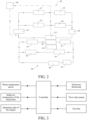
FIG. 1 is a schematic structural diagram of an engine cooling system according to an embodiment of the present disclosure; -
FIG. 2 is a schematic structural diagram of a low-temperature cooling system and an air conditioning system according to an embodiment of the present disclosure; -
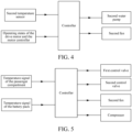
FIG. 3 is a control policy for an engine cooling system according to an embodiment of the present disclosure; -
FIG. 4 is a control policy for a low-temperature cooling system according to an embodiment of the present disclosure; -
FIG. 5 is a control policy for an air conditioning system according to an embodiment of the present disclosure; -
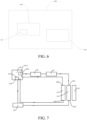
FIG. 6 is a schematic diagram of a vehicle according to an embodiment of the present disclosure; -
FIG. 7 is a schematic diagram of a detailed structure of an engine cooling system according to an embodiment of the present disclosure; and -
FIG. 8 is a schematic diagram of a detailed structure of a low-temperature cooling system and an air conditioning system according to an embodiment of the present disclosure. - In the drawings:
- 100: Thermal management system;
- 200: Vehicle; 201: Battery pack;
- 10: Engine cooling system; 11: Engine; 111: Intake manifold; 112: Supercharger; 113: First end; 114: Second end; 12: Intercooler; 121: Air outlet end; 122: Air inlet end; 13: First fan; 14: First water pump; 15: First radiator; 151: Third end; 152: Fourth end; 16: First temperature sensor; 17: Electronic thermostat;
- 20: Low-temperature cooling system; 21: Drive motor; 22: Second radiator; 23: Second water pump; 231: Liquid inlet; 24: Second fan; 25: Motor controller; 26: Generator; 27: Direct current distributor; 28: Second temperature sensor;
- 30: Air conditioning system; 31: Compressor; 32: Evaporator; 33: Condenser; 34: First control valve; 35: Second control valve; 36: Expansion kettle; 361: Water inlet; 362: Water outlet; 37: Pressure sensor; 38: Heat exchanger;
- 40: Controller.
- The embodiments of the present disclosure are described in detail below, and the embodiments described with reference to accompanying drawings are exemplary.
- A
thermal management system 100 of avehicle 200 according to an embodiment of the present disclosure is described below with reference toFIG. 1 to FIG. 5 ,FIG. 7 , andFIG. 8 . The present disclosure further provides avehicle 200 having the foregoingthermal management system 100. - As shown in
FIG. 1 ,FIG. 2 , andFIG. 7 , thethermal management system 100 of thevehicle 200 in this embodiment of the present disclosure includes anengine cooling system 10, a low-temperature cooling system 20, and anair conditioning system 30. - Specifically, the
engine cooling system 10 includes anengine 11, anintercooler 12, afirst radiator 15, and afirst fan 13. The engine includes anintake manifold 111 and asupercharger 112. Anair outlet end 121 of theintercooler 12 is in communication with theintake manifold 111, and anair inlet end 122 of theintercooler 12 is in communication with thesupercharger 112. Theengine 11 and thefirst radiator 15 are connected in series with each other. Thefirst fan 13 is configured to dissipate heat from theintercooler 12 and thefirst radiator 15. Theengine 11 and thefirst radiator 15 are arranged in series, so that heat generated during operating of theengine 11 can be carried away by a coolant and dissipated to the outside world through thefirst radiator 15. In addition, thefirst fan 13 and thefirst radiator 15 are arranged oppositely, and thefirst fan 13 faces thefirst radiator 15. Therefore, thefirst fan 13 can deliver air to thefirst radiator 15 to reduce the temperature of the coolant in thefirst radiator 15, thereby reducing the temperature of theengine cooling system 10. In addition, when theengine 11 is running, theintercooler 12 can reduce the temperature of a high-temperature gas, thereby reducing an intake air temperature of theengine 11. - Referring to
FIG. 1 , theintercooler 12 and thefirst radiator 15 are arranged oppositely, and thefirst fan 13 and thefirst radiator 15 are arranged oppositely. In such an arrangement, thefirst fan 13 can dissipate heat from both thefirst radiator 15 and theintercooler 12, so that an integration degree of thethermal management system 100 can be improved. In addition, a location where an air-cooledcondenser 33 is originally arranged may be left free, which is conducive to optimizing space of a compartment of theengine 11. In addition, the temperature of theintercooler 12 is close to the temperature of thefirst radiator 15, and the influence on each other is small, which is conducive to increasing the service life of theintercooler 12 and thefirst radiator 15. - In addition, the low-
temperature cooling system 20 includes asecond radiator 22 and asecond fan 24. Thesecond fan 24 is arranged on a side of thesecond radiator 22. Theair conditioning system 30 includes thecondenser 33. Thesecond radiator 22 and thecondenser 33 are arranged oppositely. Thesecond fan 24 is configured to dissipate heat from thesecond radiator 22 and thecondenser 33. In other words, thesecond radiator 22 of the low-temperature cooling system 20 and thecondenser 33 of theair conditioning system 30 are arranged oppositely, and thesecond fan 24 and thesecond radiator 22 are arranged oppositely. Therefore, thefirst fan 13 can dissipate heat from both thesecond radiator 22 and thecondenser 33, so that the integration degree of thethermal management system 100 can be improved. In addition, the temperature of thecondenser 33 is close to the temperature of thesecond radiator 22, and the influence on each other is small, which is conducive to increasing the service life of theintercooler 12 and thefirst radiator 15. - Therefore, the
thermal management system 100 has thefirst fan 13 and thesecond fan 24. Thefirst fan 13 and thesecond fan 24 are independently controlled. A rotation speed of thefirst fan 13 only needs to meet a cooling requirement of theintercooler 12 and thefirst radiator 15, and a rotation speed of thesecond fan 24 only needs to meet a cooling requirement of thesecond radiator 22 and thecondenser 33, which is conducive to accurate control of thermal management of the whole vehicle. Moreover, theintercooler 12 and thefirst radiator 15 share thefirst fan 13, and thesecond radiator 22 and thecondenser 33 share thesecond fan 24. Therefore, temperature interference between theintercooler 12 and thefirst radiator 15 is low, and temperature interference between thesecond radiator 22 and thecondenser 33 is also low. - As shown in
FIG. 6 , thethermal management system 100 further includes acontroller 40. Thecontroller 40 is configured to control running of theengine cooling system 10 according to a temperature of a coolant of theengine 11. Therefore, normal use of theengine cooling system 10 is facilitated. - As shown in
FIG. 1 andFIG. 7 , theengine cooling system 10 further includes afirst water pump 14 and anelectronic thermostat 17. Theelectronic thermostat 17 is arranged between a first end 113 of theengine 11 and a third end 151 of thefirst radiator 15. Thefirst water pump 14 is arranged between asecond end 114 of theengine 11 and a fourth end 152 of thefirst radiator 15. Thefirst water pump 14 can drive the coolant to circulate among theengine 11, thefirst water pump 14, and thefirst radiator 15. When the coolant flows through theengine 11, the coolant can reduce the temperature of theengine 11. When the coolant flows through thefirst radiator 15, thefirst radiator 15 can dissipate heat from the coolant. In addition, theelectronic thermostat 17 can automatically adjust the amount of water entering thefirst radiator 15 according to the temperature of the cooling water, thereby changing the circulation range of the water, to adjust the heat dissipation capability of thefirst radiator 15, and ensure that theengine 11 operates in a suitable temperature range. Theelectronic thermostat 17 needs to maintain a good technical state; otherwise, normal operating of theengine 11 is severely affected. For example, if a main valve of theelectronic thermostat 17 opens too late, theengine 11 is overheated. If the main valve opens too early, a warm-up time of theengine 11 is extended, and the temperature of theengine 11 is excessively low. - The
controller 40 is configured to adjust a rotation speed of thefirst water pump 14 and an opening degree of theelectronic thermostat 17 according to the temperature of the coolant. Specifically, theelectronic thermostat 17 can control the flow of the coolant flowing through theelectronic thermostat 17, and thefirst water pump 14 can control a flow rate of the coolant. That is to say, by controlling the temperature of the coolant and the flow of the coolant, theengine 11 can be rapidly cooled. - As shown in
FIG. 1 , theengine cooling system 10 further includes afirst temperature sensor 16. Thefirst temperature sensor 16 is arranged between thefirst radiator 15 and theengine 11. Thefirst temperature sensor 16 is configured to detect the temperature of the coolant of theengine 11. Thecontroller 40 is configured to adjust a rotation speed of thefirst fan 13 according to the temperature of the coolant. Therefore, when theengine cooling system 10 is running, thecontroller 40 can adjust the rotation speed of thefirst fan 13 according to the temperature of the coolant detected by thefirst temperature sensor 16. That is to say, by properly controlling the rotation speed of thefirst fan 13, the temperature of the coolant in theengine cooling system 10 can be controlled, so that the rotation speed of thefirst fan 13 can be controlled according to a running state of theengine 11. For example, when the rotation speed of theengine 11 increases, theengine 11 dissipates more heat to the outside world, and the temperature of the coolant also increases correspondingly. In this case, the rotation speed of thefirst fan 13 can be controlled by thecontroller 40, to control the temperature of the coolant, so that the temperature of theengine 11 is equalized or the temperature of theengine 11 is quickly reduced. - The
controller 40 is configured to: first adjust a rotation speed of thefirst water pump 14 and an opening degree of theelectronic thermostat 17 according to the temperature of the coolant, and then adjust the rotation speed of thefirst fan 13 according to the temperature of the coolant. Specifically, thecontroller 40 may first control the opening degree of theelectronic thermostat 17, and then thecontroller 40 controls the flow rate of thefirst water pump 14. Further, thecontroller 40 controls the rotation speed of thefirst fan 13. That is to say, thecontroller 40 preferentially controls a low-power actuator. Only when the low-power actuator does not meet the cooling requirement, thecontroller 40 adjusts a high-power actuator. Therefore, the energy consumption of thethermal management system 100 can be effectively reduced. - Referring to
FIG. 2 andFIG. 6 , thethermal management system 100 further includes acontroller 40. Thecontroller 40 is configured to control running of the low-temperature cooling system 20 according to a temperature of a coolant. Therefore, normal running of theengine cooling system 10 and the low-temperature cooling system 20 may be adjusted and controlled by thecontroller 40. - As shown in
FIG. 2 , The low-temperature cooling system 20 further includes asecond water pump 23, asecond temperature sensor 28, a drive motor, and amotor controller 25. The low-temperature cooling system 20 is formed with a first branch and a second branch arranged in parallel. Thesecond water pump 23, thesecond temperature sensor 28, and thesecond radiator 22 are connected in series with each other. Themotor controller 25 is electrically connected to thedrive motor 21. Thedrive motor 21 is connected to the first branch. Themotor controller 25 is connected to the second branch. In other words, thesecond water pump 23 may drive the coolant to circulate among the drivingmotor 21, themotor controller 25, and thesecond radiator 22. When the coolant flows through thedrive motor 21 and themotor controller 25, the coolant may reduce the temperature of thedrive motor 21 and the temperature of themotor controller 25. When the coolant flows through thesecond radiator 22, thesecond radiator 22 can dissipate heat from the coolant. - The
motor controller 25 is configured to control running parameters of thedrive motor 21. The low-temperature cooling system 20 is formed with the first branch and the second branch, and the second branch and the first branch are arranged in parallel with each other. Therefore, themotor controller 25, thedrive motor 21, and thesecond radiator 22 are connected in parallel with each other, so that interference among themotor controller 25, thedrive motor 21, and thesecond radiator 22 is reduced. - In addition, the
thermal management system 100 further includes acontroller 40. Thecontroller 40 is configured to adjust a rotation speed of thesecond water pump 23 and a rotation speed of thesecond fan 24 according to the temperature of the coolant. In other words, when the low-temperature cooling system 20 is running, thecontroller 40 may adjust the rotation speeds of thesecond water pump 23 and thesecond fan 24 according to the temperature of the coolant detected by thesecond temperature sensor 28. That is to say, thecontroller 40 preferentially controls the low-power actuator. When the low-power actuator does not meet the cooling requirement, thecontroller 40 adjusts the high-power actuator, so that the energy consumption of thethermal management system 100 can be effectively reduced. - As shown in
FIG. 2 , the low-temperature cooling system 20 further includes agenerator 26 and a directcurrent distributor 27. Thegenerator 26 and the directcurrent distributor 27 are both electrically connected to themotor controller 25. The directcurrent distributor 27 is connected in series with thedrive motor 21 on the first branch. Thegenerator 26 is connected in series with themotor controller 25 on the second branch. Thegenerator 26 and the directcurrent distributor 27 are not in a normally open state. By connecting theengine 11 and themotor controller 25 in series, and connecting the directcurrent distributor 27 and thedrive motor 21 in series, both the second branch and the first branch can be continuously turned on, thereby avoiding a situation in which the coolant still flows through a branch when heat is not generated in the branch. For example, when theengine 11 is used for running of thevehicle 200, some energy may be recovered. When thevehicle 200 is charged, the directcurrent distributor 27 may convert alternating current into direct current for thevehicle 200, to facilitate charging of thevehicle 200. - As shown in
FIG. 2 andFIG. 8 , the low-temperature cooling system 20 further includes anexpansion kettle 36. Theexpansion kettle 36 is provided with awater inlet 361 and awater outlet 362, thewater outlet 362 is connected to aliquid inlet 231 of thesecond water pump 23, and thewater inlet 361 is connected to thesecond radiator 22. In other words, when the flow rate of thesecond water pump 23 increases, the coolant in the low-temperature cooling system 20 is insufficient. The coolant is injected into the low-temperature cooling system 20 through theexpansion kettle 36, so that a heat exchange requirement of the low-temperature cooling system 20 can be satisfied. - As shown in
FIG. 1 , Theair conditioning system 30 includes acompressor 31, anevaporator 32, acondenser 33, and afirst control valve 34. Thecompressor 31, theevaporator 32, thecondenser 33, and thefirst control valve 34 are connected in series with each other. Thecondenser 33 and thesecond radiator 22 are arranged oppositely. In theair conditioning system 30, a high-temperature and high-pressure cooling medium compressed by thecompressor 21 enters thecondenser 22 and is condensed to become a medium-temperature and medium-pressure liquid cooling medium. Secondly, the medium-temperature and medium-pressure liquid cooling medium is throttled and depressurized through a throttling element to become a low-temperature and low-pressure liquid cooling medium. Then, the low-temperature and low-pressure liquid cooling medium enters theevaporator 24 to cool the air in the passenger compartment. - As shown in
FIG. 2 , theair conditioning system 30 further includes asecond control valve 35 and aheat exchanger 38. Theheat exchanger 38 and thesecond control valve 35 are arranged in series, theheat exchanger 38 and thesecond control valve 35 are arranged in parallel with theevaporator 32, and theheat exchanger 38 is adapted to exchange heat with abattery pack 201. In other words, theair conditioning system 30 may further exchange heat with thebattery pack 201 through theheat exchanger 38. Therefore, theair conditioning system 30 can reduce the temperature of thebattery pack 201. - In addition, the
air conditioning system 30 further includes apressure sensor 37. Thepressure sensor 37 is arranged between thecompressor 31 and thecondenser 33. Thepressure sensor 37 may be configured to detect a pressure of the coolant. - the
thermal management system 100 further includes acontroller 40. Thecontroller 40 is configured to control switching of thefirst control valve 34 and thesecond control valve 35 according to a temperature of thebattery pack 201 and a temperature of a passenger compartment, and thecontroller 40 is configured to adjust a rotation speed of thecompressor 31 and the rotation speed of thesecond fan 24. Specifically, theheat exchanger 38 and theevaporator 32 are arranged in parallel, theevaporator 32 and thefirst control valve 34 are arranged in series, and theheat exchanger 38 and thesecond control valve 35 are arranged in series. Therefore, when the passenger compartment and thebattery pack 201 have a temperature reduction need, switching of thefirst control valve 34 and thesecond control valve 35 may be selectively controlled. For example, when theevaporator 32 is in operation, thefirst control valve 34 is opened, and the coolant may pass through thefirst control valve 34 and then exchange heat at theevaporator 32, thereby reducing the temperature of the passenger compartment. When the temperature of thebattery pack 201 needs to be reduced, thesecond control valve 35 is opened, and the coolant may pass through thesecond control valve 35 and then exchange heat with thebattery pack 201 at theheat exchanger 38, thereby reducing the temperature of thebattery pack 201. - The
controller 40 may further control the rotation speed of thecompressor 31 and the rotation speed of thesecond fan 24 according to the temperature of thebattery pack 201 and the temperature of the passenger compartment. In other words, when there is a large difference between an actual temperature of thebattery pack 201 and a preset temperature of thebattery pack 201, thecontroller 40 may perform control to increase the rotation speed of thecompressor 31 and the rotation speed of thesecond fan 24. Therefore, the temperature of the coolant outputted by thecompressor 31 is lower, the temperature reduction of thebattery pack 201 is facilitated, and thesecond fan 24 can quickly dissipate heat from thecondenser 33. When a driver inputs a new preset temperature, thecontroller 40 may perform control to increase the rotation speed of thecompressor 31 and the rotation speed of thesecond fan 24, so that the temperature of the coolant outputted by thecompressor 31 is lower, the temperature reduction of thebattery pack 201 is facilitated, and thesecond fan 24 can quickly dissipate heat from thecondenser 33. - With reference to
FIG. 1 to FIG. 5 , a control policy for athermal management system 100 in an embodiment of the present disclosure is described. - With reference to
FIG. 1 andFIG. 3 , in Embodiment 1 of the present disclosure, a control method for thethermal management system 100 includes the following steps:
Theengine 11 is started. A cooling water temperature of theengine 11 is T, a rotation speed of thefirst water pump 14 is C, and a rotation speed of thefirst fan 13 is B. A relationship between the cooling water temperature T and a predetermined value T1 is determined as follows:
When T > T1, a rotation speed of thefirst water pump 14 is C1, a rotation speed of thefirst fan 13 is B1, and an opening degree of theelectronic thermostat 17 is increased. In other words, when the cooling water temperature T is greater than the predetermined value T1, the rotation speed of thefirst water pump 14 is fixed at C1, and the rotation speed of thefirst fan 13 is fixed at B1. Then, by increasing the opening degree of theelectronic thermostat 17, the flow of the coolant passing through theengine 11 can be increased, so that the temperature of theengine 11 can be effectively reduced. - If the cooling water temperature T is balanced at T1, the
first fan 13 maintains the rotation speed B1, and thefirst water pump 14 maintains the rotation speed C1. In other words, if the cooling water temperature T is balanced at T1 after the opening degree of theelectronic thermostat 17 is increased, there is no need to adjust the rotation speed of thefirst fan 13, the rotation speed of thefirst water pump 14, and the opening degree of theelectronic thermostat 17, and theengine cooling system 10 is in a state of thermal balance. Alternatively, if the cooling water temperature T is still greater than T1 when theelectronic thermostat 17 is adjusted to the maximum opening degree, the rotation speed of thefirst water pump 14 is increased to C2. In other words, if the cooling water temperature T is still greater than T1 when theelectronic thermostat 17 is adjusted to the maximum opening degree, the method for controlling the cooling water temperature by adjusting theelectronic thermostat 17 cannot be implemented. Then, the rotation speed of thefirst water pump 14 needs to be increased to C2. By increasing the rotation speed of thefirst water pump 14, the flow rate of the coolant in theengine cooling system 10 can be increased, thereby effectively reducing the temperature of theengine 11. - In addition, the step of increasing the rotation speed of the
first water pump 14 to C2 if the cooling water temperature T is still greater than T1 when theelectronic thermostat 17 is adjusted to the maximum opening degree further includes:
If the cooling water temperature T is balanced at T1, thefirst fan 13 maintains the rotation speed B1, and thefirst water pump 14 maintains the rotation speed C2. In other words, if the cooling water temperature T is balanced at T1 after the rotation speed of thefirst water pump 14 is increased, the rotation speed of thefirst water pump 14 does not need to be adjusted again, and theengine cooling system 10 is in a state of thermal balance. Alternatively, if the cooling water temperature T is still greater than T1 when the rotation speed of thefirst water pump 14 is increased to the maximum rotation speed C3, the rotation speed of thefirst fan 13 is increased to B2. In other words, if the cooling water temperature T is still greater than T1 when the rotation speed of thefirst water pump 14 is increased to the maximum rotation speed C3, the method for controlling the cooling water temperature by adjusting the rotation speed of thefirst water pump 14 cannot be implemented. Then, the rotation speed of thefirst fan 13 needs to be increased to B2. By increasing the rotation speed of thefirst fan 13, the temperature of the coolant in theengine cooling system 10 is reduced, thereby effectively reducing the temperature of theengine 11. - The step of starting the
engine 11 further includes:
When an intake air temperature of theintercooler 12 is greater than a target value, the rotation speed of thefirst fan 13 is A. A maximum value is selected from the rotation speed A of thefirst fan 13 and a rotation speed B of thefirst fan 13 as an actual rotation speed of thefirst fan 13. In other words, when both theintercooler 12 and thefirst radiator 15 need to dissipate heat, thefirst fan 13 corresponds to two heat sources. Therefore, the maximum value is selected from the rotation speed A and the rotation speed B as the actual rotation speed of thefirst fan 13, so that the temperature of theintercooler 12 and the temperature of thefirst fan 13 can be effectively reduced. - With reference to
FIG. 2 andFIG. 4 , in Embodiment 2 of the present disclosure, a control method for thethermal management system 100 includes the following steps:
Thedrive motor 21 and themotor controller 25 are started. A temperature of thesecond temperature sensor 28 is t. A relationship between the temperature t of thesecond temperature sensor 28 and a predetermined value t1 is determined as follows:
When t > t1, a rotation speed of thesecond fan 24 is E1, and a rotation speed of thesecond water pump 23 is increased to D1. In other words, when the cooling water temperature t is greater than the predetermined value t1, the rotation speed of thesecond fan 24 is fixed at E1. Then, by increasing the rotation speed of thesecond water pump 23 to D1, the flow rate of the coolant flowing through theengine 11 is increased, so that the temperature of theengine 11 can be effectively reduced. - If the temperature t is balanced at t1, the
second fan 24 maintains the rotation speed E1, and thesecond water pump 23 maintains the rotation speed D1. In other words, if the cooling water temperature t is balanced at t1 after the rotation speed of thesecond water pump 23 is increased, the rotation speed of thesecond water pump 23 does not need to be adjusted again, and the low-temperature cooling system 20 is in a state of thermal balance. Alternatively, if the temperature t is still greater than t1 when the rotation speed of thesecond water pump 23 is increased to the maximum rotation speed D2, the rotation speed of thesecond fan 24 is increased to E2. In other words, if the cooling water temperature t is still greater than t1 when the rotation speed of thesecond water pump 23 is increased to the maximum rotation speed D2, the method for controlling the cooling water temperature by adjusting the rotation speed of thesecond water pump 23 cannot be implemented. Then, the rotation speed of thesecond fan 24 needs to be increased to E2. By increasing the rotation speed of thesecond fan 24, the temperature of the coolant in the low-temperature cooling system 20 can be reduced, so that the temperature of thedrive motor 21 and the temperature of themotor controller 25 can be effectively reduced. - With reference to
FIG. 2 andFIG. 4 , in Embodiment 3 of the present disclosure, a control method for thethermal management system 100 includes the following steps:
Thecompressor 31 is started and the coolant flows through theevaporator 32, where an actual temperature of the passenger compartment is h, and a rotation speed of thesecond fan 24 is G1; and a relationship between the temperature h and a first predetermined value h1 is determined as follows:
When h ≤ h1, a rotation speed of thecompressor 31 is F1-1, and a rotation speed of thesecond fan 24 is G1-1. In other words, if the cooling water temperature h is balanced at h1 when the rotation speed of thecompressor 31 is fixed at F1-1 and the rotation speed of thesecond fan 24 is fixed at G1-1, there is no need to adjust the rotation speeds of thecompressor 31 and thesecond fan 24, and theair conditioning system 30 is in a state of thermal balance. - When h > h1, the rotation speed of the
compressor 31 is F1-1, and the rotation speed of thesecond fan 24 is increased to G1-2. In other words, when the cooling water temperature h is greater than the predetermined value h1, the rotation speed of thecompressor 31 is fixed at F1-1. Then, by increasing the rotation speed of thesecond fan 24 to G1-2, that is, by increasing the rotation speed of thesecond fan 24, the temperature of the coolant in theair conditioning system 30 is reduced. - If the temperature h is balanced at h1, the
second fan 24 maintains the rotation speed G1-2. In other words, if the cooling water temperature h is balanced at h1 after the rotation speed of thesecond fan 24 is increased, the rotation speed of thesecond fan 24 does not need to be adjusted again, and theair conditioning system 30 is in a state of thermal balance. Alternatively, if the temperature h is still greater than h1 when the rotation speed of thesecond fan 24 is increased to the maximum rotation speed G1-3, the rotation speed of thecompressor 31 is increased to F1-2. In other words, if the cooling water temperature h is still greater than h1 when the rotation speed of thesecond fan 24 is increased to the maximum rotation speed G1-3, the method for controlling the cooling water temperature by adjusting the rotation speed of thesecond fan 24 cannot be implemented. Then, the rotation speed of thecompressor 31 needs to be increased to F1-2. By increasing the rotation speed of thecompressor 31, the flow of the coolant in theair conditioning system 30 can be increased, thereby effectively reducing the temperature of the passenger compartment. - In addition, the foregoing step in which the
compressor 31 is started and the coolant flows through theevaporator 32, where an actual temperature of the passenger compartment is h further includes:
Thesecond control valve 35 is opened, where an actual temperature of thebattery pack 201 is i, and a rotation speed of thesecond fan 24 is G2, and a relationship between the temperature i and a first predetermined value i1 is determined. In other words, if thesecond control valve 35 is opened when the temperature of thebattery pack 201 needs to be reduced, a control policy for the rotation speed of thesecond fan 24 and the rotation speed of thecompressor 31 is as follows:
When i ≤ i1, a rotation speed of thecompressor 31 is F2-1, and a rotation speed of thesecond fan 24 is G2-1. In other words, if the cooling water temperature i is balanced at i1 when the rotation speed of thecompressor 31 is fixed at F2-1 and the rotation speed of thesecond fan 24 is fixed at G2-1, there is no need to adjust the rotation speeds of thecompressor 31 and thesecond fan 24, and theair conditioning system 30 is in a state of thermal balance. - When i > i1, the rotation speed of the
compressor 31 is F2-1, and the rotation speed of thesecond fan 24 is increased to G2-2. In other words, when the cooling water temperature i is greater than the predetermined value i1, the rotation speed of thecompressor 31 is fixed at F2-1. Then, by increasing the rotation speed of thesecond fan 24 to G2-2, that is, by increasing the rotation speed of thesecond fan 24, the temperature of the coolant in theair conditioning system 30 is reduced. - If the temperature i is balanced at i1, the
second fan 24 maintains the rotation speed G2-2. In other words, if the cooling water temperature i is balanced at i1 after the rotation speed of thesecond fan 24 is increased, the rotation speed of thesecond fan 24 does not need to be adjusted again, and theair conditioning system 30 is in a state of thermal balance. Alternatively, if the temperature i is still greater than i1 when the rotation speed of thesecond fan 24 is increased to the maximum rotation speed G2-3, the rotation speed of thecompressor 31 is increased to F2-2. In other words, if the cooling water temperature i is still greater than i1 when the rotation speed of thesecond fan 24 is increased to the maximum rotation speed G2-3, the method for controlling the cooling water temperature by adjusting the rotation speed of thesecond fan 24 cannot be implemented. Then, the rotation speed of thecompressor 31 needs to be increased to F2-2. By increasing the rotation speed of thecompressor 31, the flow of the coolant in theair conditioning system 30 can be increased, thereby effectively reducing the temperature of thebattery pack 201. - When both the passenger compartment and the
battery pack 201 have a cooling need, a maximum value of the rotation speed G1 and the rotation speed G2 is an actual rotation speed of thesecond fan 24. In other words, when both the passenger compartment and thebattery pack 201 need to dissipate heat, the temperature of the coolant is relatively high. Therefore, a maximum value is selected from the rotation speed G1 and the rotation speed G2 as the actual rotation speed of thesecond fan 24, so that the temperature of the passenger compartment and the temperature of thebattery pack 201 can be effectively reduced. - A
vehicle 200 according to an embodiment of a second aspect of the present disclosure includes, with reference toFIG. 6 , the foregoingthermal management system 100. - In the description of the present disclosure, it should be understood that orientation or position relationships indicated by the terms such as "center", "longitudinal", "transverse", "length", "width", "thickness", "on", "below", "front", "back", "left", "right", "vertical", "horizontal", "top", "bottom", "inside", "outside", "clockwise", "anticlockwise", "axial direction", "radial direction", and "circumferential direction" are based on orientation or position relationships shown in the accompanying drawings, and are used only for ease and brevity of illustration and description, rather than indicating or implying that the mentioned apparatus or component needs to have a particular orientation or needs to be constructed and operated in a particular orientation.
- In the description of this specification, the description of the reference terms such as "an embodiment", "some embodiments", "exemplary embodiments", "example", "specific example", or "some examples" means that the specific features, structures, materials or characteristics described with reference to the embodiment or example are included in at least one embodiment or example of the present disclosure. In this specification, schematic descriptions of the foregoing terms do not necessarily directed at a same embodiment or example.
- Although the embodiments of the present disclosure have been shown and described, a person of ordinary skill in the art should understand that various changes, modifications, replacements and variations may be made to the embodiments without departing from the principles and spirit of the present disclosure, and the scope of the present disclosure is as defined by the appended claims and their equivalents.
Claims (13)
- A thermal management system (100) of a vehicle (200), comprising:
an engine cooling system (10), the engine cooling system (10) comprising:an engine (11), the engine comprising an intake manifold (111) and a supercharger (112),an intercooler (12), an air outlet end (121) of the intercooler (12) being in communication with the intake manifold (111), and an air inlet end (122) of the intercooler (12) being in communication with the supercharger (112),a first radiator (15), the first radiator (15) being connected to the engine (11), anda first fan (13), the first fan (13) being configured to dissipate heat from the intercooler (12) and the first radiator (15);an air conditioning system (30), the air conditioning system (30) comprising a condenser (33); anda low-temperature cooling system (20), the low-temperature cooling system (20) comprising:a second radiator (22), anda second fan (24), the second fan (24) being configured to dissipate heat from the second radiator (22) and the condenser (33). - The thermal management system (100) of the vehicle (200) according to claim 1, the thermal management system (100) further comprising:
a controller (40), the controller (40) being configured to control running of the engine cooling system (10) according to a temperature of a coolant of the engine (11). - The thermal management system (100) of the vehicle (200) according to claim 2, wherein the engine cooling system (10) further comprises:an electronic thermostat (17), the electronic thermostat (17) is arranged between a first end (113) of the engine (11) and a third end (151) of the first radiator (15); anda first water pump (14), the first water pump (14) is arranged between a second end (114) of the engine (11) and a fourth end (152) of the first radiator (15);wherein the controller (40) is configured to adjust a rotation speed of the first water pump (14) and an opening degree of the electronic thermostat (17) according to the temperature of the coolant of the engine (11).
- The thermal management system (100) of the vehicle (200) according to claim 2, wherein the engine cooling system (10) further comprises: a first temperature sensor (16), the first temperature sensor (16) is arranged between the first radiator (15) and the engine (11), and the first temperature sensor (16) is configured to detect the temperature of the coolant of the engine (11); and
the controller (40) is configured to adjust a rotation speed of the first fan (13) according to the temperature of the coolant of the engine (11). - The thermal management system (100) of the vehicle (200) according to claim 4, wherein the controller (40) is configured to:
first adjust a rotation speed of the first water pump (14) and an opening degree of the electronic thermostat (17) according to the temperature of the coolant, and then adjust the rotation speed of the first fan (13) according to the temperature of the coolant. - The thermal management system (100) of the vehicle (200) according to claim 1, the thermal management system (100) further comprising:
a controller (40), the controller (40) being configured to control running of the low-temperature cooling system (20) according to a temperature of a coolant. - The thermal management system (100) of the vehicle (200) according to claim 6, wherein the low-temperature cooling system (20) is formed with a first branch and a second branch arranged in parallel, and the low-temperature cooling system (20) further comprises:a second water pump (23);a second temperature sensor (28), the second temperature sensor (28) is connected in series with the second water pump (23) and the second radiator (22);a drive motor (21), the drive motor (21) is connected to the first branch; anda motor controller (25), the motor controller (25) is electrically connected to the drive motor (21), and the motor controller (25) is connected to the second branch;wherein the controller (40) is configured to adjust a rotation speed of the second water pump (23) and a rotation speed of the second fan (24) according to the temperature of the coolant.
- The thermal management system (100) of the vehicle (200) according to claim 7, wherein the low-temperature cooling system (20) further comprises:a generator (26), the generator (26) is electrically connected to the motor controller (25), and the generator (26) is connected in series with the motor controller (25) on the second branch; anda direct current distributor (27), the direct current distributor (27) is electrically connected to the motor controller (25), and the direct current distributor (27) is connected in series with the drive motor (21) on the first branch.
- The thermal management system (100) of the vehicle (200) according to claim 7 or 8, further comprising:
an expansion kettle (36), the expansion kettle (36) being provided with a water inlet (361) and a water outlet (362), the water outlet (362) being connected to a liquid inlet (231) of the second water pump (23), and the water inlet (361) being in communication with the second radiator (22). - The thermal management system (100) of the vehicle (200) according to any one of claims 1 to 9, wherein the air conditioning system (30) comprises:a compressor (31);an evaporator (32); anda first control valve (34), the first control valve (34) is connected in series with the compressor (31), the evaporator (32), and the condenser (33).
- The thermal management system (100) of the vehicle (200) according to claim 10, wherein the air conditioning system (30) further comprises:a second control valve (35); anda heat exchanger (38), the heat exchanger (38) and the second control valve (35) are arranged in series, the heat exchanger (38) and the second control valve (35) are arranged in parallel with the evaporator (32), and the heat exchanger (38) is adapted to exchange heat with a battery pack (201).
- The thermal management system (100) of the vehicle (200) according to claim 11, the thermal management system (100) further comprising:
a controller (40), the controller (40) being configured to control switching of the first control valve (34) and the second control valve (35) according to a temperature of the battery pack (201) and a temperature of a passenger compartment, and the controller (40) being configured to adjust a rotation speed of the compressor (31) and the rotation speed of the second fan (24). - A vehicle (200), comprising: the thermal management system (100) of the vehicle (200) according to any one of claims 1 to 12.
Applications Claiming Priority (2)
| Application Number | Priority Date | Filing Date | Title |
|---|---|---|---|
| CN202210606463.7A CN117183645A (en) | 2022-05-31 | 2022-05-31 | Thermal management system of vehicle and vehicle |
| PCT/CN2023/094482 WO2023231765A1 (en) | 2022-05-31 | 2023-05-16 | Vehicle thermal management system and vehicle |
Publications (2)
| Publication Number | Publication Date |
|---|---|
| EP4520559A1 true EP4520559A1 (en) | 2025-03-12 |
| EP4520559A4 EP4520559A4 (en) | 2025-08-13 |
Family
ID=88998475
Family Applications (1)
| Application Number | Title | Priority Date | Filing Date |
|---|---|---|---|
| EP23814950.4A Pending EP4520559A4 (en) | 2022-05-31 | 2023-05-16 | HEAT MANAGEMENT SYSTEM FOR A VEHICLE AND VEHICLE |
Country Status (6)
| Country | Link |
|---|---|
| US (1) | US20250010690A1 (en) |
| EP (1) | EP4520559A4 (en) |
| JP (1) | JP2025515828A (en) |
| CN (1) | CN117183645A (en) |
| CA (1) | CA3250026A1 (en) |
| WO (1) | WO2023231765A1 (en) |
Families Citing this family (1)
| Publication number | Priority date | Publication date | Assignee | Title |
|---|---|---|---|---|
| CN118906753A (en) * | 2024-09-12 | 2024-11-08 | 一汽解放汽车有限公司 | Hybrid electric vehicle thermal management system and hybrid electric vehicle |
Family Cites Families (11)
| Publication number | Priority date | Publication date | Assignee | Title |
|---|---|---|---|---|
| US6230668B1 (en) * | 2000-05-22 | 2001-05-15 | General Electric Company | Locomotive cooling system |
| JP2012111251A (en) * | 2010-11-19 | 2012-06-14 | Mitsubishi Heavy Ind Ltd | Air conditioner for vehicle |
| SE542204C2 (en) * | 2016-06-09 | 2020-03-10 | Scania Cv Ab | A cooling system for an electric power unit in a vehicle |
| CN107499086B (en) * | 2017-05-22 | 2020-01-17 | 宝沃汽车(中国)有限公司 | Vehicle thermal management system and vehicle |
| DE102017121188B3 (en) * | 2017-09-13 | 2019-02-21 | Borgward Trademark Holdings Gmbh | Vehicle thermal management system and vehicle |
| CN209813715U (en) * | 2018-11-29 | 2019-12-20 | 比亚迪股份有限公司 | Vehicle thermal management systems and vehicles |
| WO2020121923A1 (en) * | 2018-12-14 | 2020-06-18 | 株式会社デンソー | Vehicle heat exchange system |
| CN109927534B (en) * | 2019-03-20 | 2023-04-25 | 天津大学 | Thermal management system and control method of a hybrid electric heavy-duty truck |
| CN109910592A (en) * | 2019-04-09 | 2019-06-21 | 冯志成 | A kind of cooling system and its control method of hybrid vehicle integrated heat dissipation |
| CN213920593U (en) * | 2020-09-21 | 2021-08-10 | 比亚迪股份有限公司 | Vehicle thermal management system and electric vehicle |
| CN213472754U (en) * | 2020-11-16 | 2021-06-18 | 浙江吉利控股集团有限公司 | A thermal management system and vehicle |
-
2022
- 2022-05-31 CN CN202210606463.7A patent/CN117183645A/en active Pending
-
2023
- 2023-05-16 JP JP2024566712A patent/JP2025515828A/en active Pending
- 2023-05-16 WO PCT/CN2023/094482 patent/WO2023231765A1/en not_active Ceased
- 2023-05-16 EP EP23814950.4A patent/EP4520559A4/en active Pending
- 2023-05-16 CA CA3250026A patent/CA3250026A1/en active Pending
-
2024
- 2024-09-23 US US18/893,199 patent/US20250010690A1/en active Pending
Also Published As
| Publication number | Publication date |
|---|---|
| CN117183645A (en) | 2023-12-08 |
| WO2023231765A1 (en) | 2023-12-07 |
| CA3250026A1 (en) | 2025-06-17 |
| EP4520559A4 (en) | 2025-08-13 |
| JP2025515828A (en) | 2025-05-20 |
| US20250010690A1 (en) | 2025-01-09 |
Similar Documents
| Publication | Publication Date | Title |
|---|---|---|
| CN110962529B (en) | Vehicle thermal management system | |
| JP7185469B2 (en) | vehicle thermal management system | |
| EP3621839B1 (en) | A cooling arrangement for cooling of an electric machine and at least one further component of an electric power unit and a vehicle comprising such a cooling arrangement | |
| CN109572486B (en) | Thermal management system and control method for power battery of hybrid electric vehicle | |
| CN114335595A (en) | A fuel cell vehicle thermal management system and its control method | |
| US10308096B2 (en) | HVAC system of vehicle | |
| CN116278626B (en) | A thermal management system for hybrid vehicles | |
| CN113733848B (en) | Integrated water-cooling hybrid electric vehicle thermal management system | |
| AU2022356849B2 (en) | Thermal management system and vehicle having same | |
| CN110962530A (en) | Vehicle thermal management system | |
| US20210387506A1 (en) | In-vehicle temperature control system | |
| CN113291128B (en) | Integrated power battery cooling system, cooling control method and electric automobile | |
| US11207940B2 (en) | Integrated thermal management system for vehicle | |
| KR102343079B1 (en) | Device and method for cooling battery cell modules | |
| US11085354B2 (en) | Control method for integrated thermal management system of vehicle | |
| JP2020185908A (en) | Temperature control device for electric vehicle | |
| US20250010690A1 (en) | Vehicle thermal management system and vehicle | |
| EP4552872A1 (en) | Thermal management assembly, thermal management system, and vehicle | |
| CN117719298A (en) | An integrated thermal management system for hybrid electric vehicles and its control method | |
| JP2022053940A (en) | Circuit temperature control system of vehicle | |
| CN117183648B (en) | Thermal management system of vehicle and vehicle | |
| JP7823231B2 (en) | Temperature control system and vehicle having the same | |
| KR102962268B1 (en) | Apparatus of controlling active air flap | |
| CN222136394U (en) | Thermal management system, vehicle | |
| CN121291049A (en) | A thermal management integrated system for hybrid commercial vehicles |
Legal Events
| Date | Code | Title | Description |
|---|---|---|---|
| STAA | Information on the status of an ep patent application or granted ep patent |
Free format text: STATUS: THE INTERNATIONAL PUBLICATION HAS BEEN MADE |
|
| PUAI | Public reference made under article 153(3) epc to a published international application that has entered the european phase |
Free format text: ORIGINAL CODE: 0009012 |
|
| STAA | Information on the status of an ep patent application or granted ep patent |
Free format text: STATUS: REQUEST FOR EXAMINATION WAS MADE |
|
| 17P | Request for examination filed |
Effective date: 20241204 |
|
| AK | Designated contracting states |
Kind code of ref document: A1 Designated state(s): AL AT BE BG CH CY CZ DE DK EE ES FI FR GB GR HR HU IE IS IT LI LT LU LV MC ME MK MT NL NO PL PT RO RS SE SI SK SM TR |
|
| A4 | Supplementary search report drawn up and despatched |
Effective date: 20250711 |
|
| RIC1 | Information provided on ipc code assigned before grant |
Ipc: B60H 1/00 20060101AFI20250707BHEP Ipc: B60L 58/26 20190101ALI20250707BHEP Ipc: H01M 10/613 20140101ALI20250707BHEP Ipc: H01M 10/625 20140101ALI20250707BHEP Ipc: H01M 10/6556 20140101ALI20250707BHEP Ipc: H01M 10/6568 20140101ALI20250707BHEP Ipc: H01M 10/6569 20140101ALI20250707BHEP Ipc: F01P 5/02 20060101ALI20250707BHEP Ipc: F01P 7/16 20060101ALI20250707BHEP Ipc: F16K 31/02 20060101ALI20250707BHEP Ipc: B60K 11/04 20060101ALI20250707BHEP Ipc: B60K 11/06 20060101ALI20250707BHEP Ipc: H01M 10/663 20140101ALI20250707BHEP Ipc: F01P 7/14 20060101ALN20250707BHEP Ipc: B60H 1/32 20060101ALN20250707BHEP |
|
| DAV | Request for validation of the european patent (deleted) | ||
| DAX | Request for extension of the european patent (deleted) |