EP4520536A1 - System and method for reducing plastic waste in inkjet printers - Google Patents
System and method for reducing plastic waste in inkjet printers Download PDFInfo
- Publication number
- EP4520536A1 EP4520536A1 EP24194355.4A EP24194355A EP4520536A1 EP 4520536 A1 EP4520536 A1 EP 4520536A1 EP 24194355 A EP24194355 A EP 24194355A EP 4520536 A1 EP4520536 A1 EP 4520536A1
- Authority
- EP
- European Patent Office
- Prior art keywords
- ink supply
- bladder
- waste
- supply container
- ink
- Prior art date
- Legal status (The legal status is an assumption and is not a legal conclusion. Google has not performed a legal analysis and makes no representation as to the accuracy of the status listed.)
- Pending
Links
Images



Classifications
-
- B—PERFORMING OPERATIONS; TRANSPORTING
- B41—PRINTING; LINING MACHINES; TYPEWRITERS; STAMPS
- B41J—TYPEWRITERS; SELECTIVE PRINTING MECHANISMS, i.e. MECHANISMS PRINTING OTHERWISE THAN FROM A FORME; CORRECTION OF TYPOGRAPHICAL ERRORS
- B41J2/00—Typewriters or selective printing mechanisms characterised by the printing or marking process for which they are designed
- B41J2/005—Typewriters or selective printing mechanisms characterised by the printing or marking process for which they are designed characterised by bringing liquid or particles selectively into contact with a printing material
- B41J2/01—Ink jet
- B41J2/17—Ink jet characterised by ink handling
- B41J2/1721—Collecting waste ink; Collectors therefor
-
- B—PERFORMING OPERATIONS; TRANSPORTING
- B41—PRINTING; LINING MACHINES; TYPEWRITERS; STAMPS
- B41J—TYPEWRITERS; SELECTIVE PRINTING MECHANISMS, i.e. MECHANISMS PRINTING OTHERWISE THAN FROM A FORME; CORRECTION OF TYPOGRAPHICAL ERRORS
- B41J2/00—Typewriters or selective printing mechanisms characterised by the printing or marking process for which they are designed
- B41J2/005—Typewriters or selective printing mechanisms characterised by the printing or marking process for which they are designed characterised by bringing liquid or particles selectively into contact with a printing material
- B41J2/01—Ink jet
- B41J2/135—Nozzles
- B41J2/165—Prevention or detection of nozzle clogging, e.g. cleaning, capping or moistening for nozzles
- B41J2/16505—Caps, spittoons or covers for cleaning or preventing drying out
- B41J2/16508—Caps, spittoons or covers for cleaning or preventing drying out connected with the printer frame
-
- B—PERFORMING OPERATIONS; TRANSPORTING
- B41—PRINTING; LINING MACHINES; TYPEWRITERS; STAMPS
- B41J—TYPEWRITERS; SELECTIVE PRINTING MECHANISMS, i.e. MECHANISMS PRINTING OTHERWISE THAN FROM A FORME; CORRECTION OF TYPOGRAPHICAL ERRORS
- B41J2/00—Typewriters or selective printing mechanisms characterised by the printing or marking process for which they are designed
- B41J2/005—Typewriters or selective printing mechanisms characterised by the printing or marking process for which they are designed characterised by bringing liquid or particles selectively into contact with a printing material
- B41J2/01—Ink jet
- B41J2/135—Nozzles
- B41J2/165—Prevention or detection of nozzle clogging, e.g. cleaning, capping or moistening for nozzles
- B41J2/16517—Cleaning of print head nozzles
- B41J2/1652—Cleaning of print head nozzles by driving a fluid through the nozzles to the outside thereof, e.g. by applying pressure to the inside or vacuum at the outside of the print head
-
- B—PERFORMING OPERATIONS; TRANSPORTING
- B41—PRINTING; LINING MACHINES; TYPEWRITERS; STAMPS
- B41J—TYPEWRITERS; SELECTIVE PRINTING MECHANISMS, i.e. MECHANISMS PRINTING OTHERWISE THAN FROM A FORME; CORRECTION OF TYPOGRAPHICAL ERRORS
- B41J2/00—Typewriters or selective printing mechanisms characterised by the printing or marking process for which they are designed
- B41J2/005—Typewriters or selective printing mechanisms characterised by the printing or marking process for which they are designed characterised by bringing liquid or particles selectively into contact with a printing material
- B41J2/01—Ink jet
- B41J2/135—Nozzles
- B41J2/165—Prevention or detection of nozzle clogging, e.g. cleaning, capping or moistening for nozzles
- B41J2/16517—Cleaning of print head nozzles
- B41J2/1652—Cleaning of print head nozzles by driving a fluid through the nozzles to the outside thereof, e.g. by applying pressure to the inside or vacuum at the outside of the print head
- B41J2/16523—Waste ink transport from caps or spittoons, e.g. by suction
-
- B—PERFORMING OPERATIONS; TRANSPORTING
- B41—PRINTING; LINING MACHINES; TYPEWRITERS; STAMPS
- B41J—TYPEWRITERS; SELECTIVE PRINTING MECHANISMS, i.e. MECHANISMS PRINTING OTHERWISE THAN FROM A FORME; CORRECTION OF TYPOGRAPHICAL ERRORS
- B41J2/00—Typewriters or selective printing mechanisms characterised by the printing or marking process for which they are designed
- B41J2/005—Typewriters or selective printing mechanisms characterised by the printing or marking process for which they are designed characterised by bringing liquid or particles selectively into contact with a printing material
- B41J2/01—Ink jet
- B41J2/135—Nozzles
- B41J2/165—Prevention or detection of nozzle clogging, e.g. cleaning, capping or moistening for nozzles
- B41J2/16517—Cleaning of print head nozzles
- B41J2/1652—Cleaning of print head nozzles by driving a fluid through the nozzles to the outside thereof, e.g. by applying pressure to the inside or vacuum at the outside of the print head
- B41J2/16526—Cleaning of print head nozzles by driving a fluid through the nozzles to the outside thereof, e.g. by applying pressure to the inside or vacuum at the outside of the print head by applying pressure only
-
- B—PERFORMING OPERATIONS; TRANSPORTING
- B41—PRINTING; LINING MACHINES; TYPEWRITERS; STAMPS
- B41J—TYPEWRITERS; SELECTIVE PRINTING MECHANISMS, i.e. MECHANISMS PRINTING OTHERWISE THAN FROM A FORME; CORRECTION OF TYPOGRAPHICAL ERRORS
- B41J2/00—Typewriters or selective printing mechanisms characterised by the printing or marking process for which they are designed
- B41J2/005—Typewriters or selective printing mechanisms characterised by the printing or marking process for which they are designed characterised by bringing liquid or particles selectively into contact with a printing material
- B41J2/01—Ink jet
- B41J2/17—Ink jet characterised by ink handling
- B41J2/175—Ink supply systems ; Circuit parts therefor
-
- B—PERFORMING OPERATIONS; TRANSPORTING
- B41—PRINTING; LINING MACHINES; TYPEWRITERS; STAMPS
- B41J—TYPEWRITERS; SELECTIVE PRINTING MECHANISMS, i.e. MECHANISMS PRINTING OTHERWISE THAN FROM A FORME; CORRECTION OF TYPOGRAPHICAL ERRORS
- B41J2/00—Typewriters or selective printing mechanisms characterised by the printing or marking process for which they are designed
- B41J2/005—Typewriters or selective printing mechanisms characterised by the printing or marking process for which they are designed characterised by bringing liquid or particles selectively into contact with a printing material
- B41J2/01—Ink jet
- B41J2/17—Ink jet characterised by ink handling
- B41J2/175—Ink supply systems ; Circuit parts therefor
- B41J2/17503—Ink cartridges
- B41J2/17513—Inner structure
-
- B—PERFORMING OPERATIONS; TRANSPORTING
- B41—PRINTING; LINING MACHINES; TYPEWRITERS; STAMPS
- B41J—TYPEWRITERS; SELECTIVE PRINTING MECHANISMS, i.e. MECHANISMS PRINTING OTHERWISE THAN FROM A FORME; CORRECTION OF TYPOGRAPHICAL ERRORS
- B41J2/00—Typewriters or selective printing mechanisms characterised by the printing or marking process for which they are designed
- B41J2/005—Typewriters or selective printing mechanisms characterised by the printing or marking process for which they are designed characterised by bringing liquid or particles selectively into contact with a printing material
- B41J2/01—Ink jet
- B41J2/17—Ink jet characterised by ink handling
- B41J2/175—Ink supply systems ; Circuit parts therefor
- B41J2/17503—Ink cartridges
- B41J2/1752—Mounting within the printer
-
- B—PERFORMING OPERATIONS; TRANSPORTING
- B41—PRINTING; LINING MACHINES; TYPEWRITERS; STAMPS
- B41J—TYPEWRITERS; SELECTIVE PRINTING MECHANISMS, i.e. MECHANISMS PRINTING OTHERWISE THAN FROM A FORME; CORRECTION OF TYPOGRAPHICAL ERRORS
- B41J2/00—Typewriters or selective printing mechanisms characterised by the printing or marking process for which they are designed
- B41J2/005—Typewriters or selective printing mechanisms characterised by the printing or marking process for which they are designed characterised by bringing liquid or particles selectively into contact with a printing material
- B41J2/01—Ink jet
- B41J2/17—Ink jet characterised by ink handling
- B41J2/175—Ink supply systems ; Circuit parts therefor
- B41J2/17503—Ink cartridges
- B41J2/17556—Means for regulating the pressure in the cartridge
-
- B—PERFORMING OPERATIONS; TRANSPORTING
- B41—PRINTING; LINING MACHINES; TYPEWRITERS; STAMPS
- B41J—TYPEWRITERS; SELECTIVE PRINTING MECHANISMS, i.e. MECHANISMS PRINTING OTHERWISE THAN FROM A FORME; CORRECTION OF TYPOGRAPHICAL ERRORS
- B41J2/00—Typewriters or selective printing mechanisms characterised by the printing or marking process for which they are designed
- B41J2/005—Typewriters or selective printing mechanisms characterised by the printing or marking process for which they are designed characterised by bringing liquid or particles selectively into contact with a printing material
- B41J2/01—Ink jet
- B41J2/17—Ink jet characterised by ink handling
- B41J2/175—Ink supply systems ; Circuit parts therefor
- B41J2/17503—Ink cartridges
- B41J2/17559—Cartridge manufacturing
-
- B—PERFORMING OPERATIONS; TRANSPORTING
- B41—PRINTING; LINING MACHINES; TYPEWRITERS; STAMPS
- B41J—TYPEWRITERS; SELECTIVE PRINTING MECHANISMS, i.e. MECHANISMS PRINTING OTHERWISE THAN FROM A FORME; CORRECTION OF TYPOGRAPHICAL ERRORS
- B41J2/00—Typewriters or selective printing mechanisms characterised by the printing or marking process for which they are designed
- B41J2/005—Typewriters or selective printing mechanisms characterised by the printing or marking process for which they are designed characterised by bringing liquid or particles selectively into contact with a printing material
- B41J2/01—Ink jet
- B41J2/17—Ink jet characterised by ink handling
- B41J2/175—Ink supply systems ; Circuit parts therefor
- B41J2/17566—Ink level or ink residue control
-
- B—PERFORMING OPERATIONS; TRANSPORTING
- B41—PRINTING; LINING MACHINES; TYPEWRITERS; STAMPS
- B41J—TYPEWRITERS; SELECTIVE PRINTING MECHANISMS, i.e. MECHANISMS PRINTING OTHERWISE THAN FROM A FORME; CORRECTION OF TYPOGRAPHICAL ERRORS
- B41J2/00—Typewriters or selective printing mechanisms characterised by the printing or marking process for which they are designed
- B41J2/005—Typewriters or selective printing mechanisms characterised by the printing or marking process for which they are designed characterised by bringing liquid or particles selectively into contact with a printing material
- B41J2/01—Ink jet
- B41J2/17—Ink jet characterised by ink handling
- B41J2/1721—Collecting waste ink; Collectors therefor
- B41J2/1728—Closed waste ink collectors
- B41J2/1735—Closed waste ink collectors with ink supply tank in common containers
-
- B—PERFORMING OPERATIONS; TRANSPORTING
- B41—PRINTING; LINING MACHINES; TYPEWRITERS; STAMPS
- B41J—TYPEWRITERS; SELECTIVE PRINTING MECHANISMS, i.e. MECHANISMS PRINTING OTHERWISE THAN FROM A FORME; CORRECTION OF TYPOGRAPHICAL ERRORS
- B41J2/00—Typewriters or selective printing mechanisms characterised by the printing or marking process for which they are designed
- B41J2/005—Typewriters or selective printing mechanisms characterised by the printing or marking process for which they are designed characterised by bringing liquid or particles selectively into contact with a printing material
- B41J2/01—Ink jet
- B41J2/135—Nozzles
- B41J2/165—Prevention or detection of nozzle clogging, e.g. cleaning, capping or moistening for nozzles
- B41J2002/16594—Pumps or valves for cleaning
-
- B—PERFORMING OPERATIONS; TRANSPORTING
- B41—PRINTING; LINING MACHINES; TYPEWRITERS; STAMPS
- B41J—TYPEWRITERS; SELECTIVE PRINTING MECHANISMS, i.e. MECHANISMS PRINTING OTHERWISE THAN FROM A FORME; CORRECTION OF TYPOGRAPHICAL ERRORS
- B41J2/00—Typewriters or selective printing mechanisms characterised by the printing or marking process for which they are designed
- B41J2/005—Typewriters or selective printing mechanisms characterised by the printing or marking process for which they are designed characterised by bringing liquid or particles selectively into contact with a printing material
- B41J2/01—Ink jet
- B41J2/17—Ink jet characterised by ink handling
- B41J2/175—Ink supply systems ; Circuit parts therefor
- B41J2/17503—Ink cartridges
- B41J2/17513—Inner structure
- B41J2002/17516—Inner structure comprising a collapsible ink holder, e.g. a flexible bag
Definitions
- This disclosure relates generally to devices that produce ink images on media, and more particularly, to the reducing of plastic waste produced by such printers.
- Inkjet imaging devices also known as inkjet printers, eject liquid ink from printheads to form images on an image receiving surface.
- the printheads include a plurality of inkjets that are arranged in an array. Each inkjet has a thermal or piezoelectric actuator that is coupled to a printhead controller.
- the printhead controller generates firing signals that correspond to digital data content that define the images.
- the actuators in the printheads respond to the firing signals by expanding into an ink chamber fluidly connected to a nozzle to eject ink drops from the nozzle onto an image receiving surface to form an ink image that corresponds to the digital image content used to generate the firing signals.
- the image receiving surface is usually a continuous web of media material or a series of media sheets.
- Inkjet printers used for producing color images typically include multiple printhead modules.
- Each printhead module includes one or more printheads that typically eject a single color of ink.
- four printhead modules are positioned in a process direction with each printhead module ejecting a different color of ink.
- the four ink colors most frequently used are cyan, magenta, yellow, and black.
- the common nomenclature for such printers is CMYK color printers.
- Some CMYK color printers have two printhead modules that print each color of ink.
- the printhead modules that print the same color of ink are offset from each other by one-half of the distance between adjacent inkjets in the cross-process direction to double the number of pixels per inch to increase the density of a line of the color of ink ejected by the printheads in the two modules.
- process direction means the direction of movement of the image receiving surface as it passes the printheads in the printer and the term “cross-process direction” means a direction that is perpendicular to the process direction in the plane of the image receiving surface.
- Inkjets especially those in printheads that eject aqueous inks, need to fire regularly to help prevent the ink in the nozzles from drying.
- the nozzles in a printhead dry because the inkjets have ejected a substantial amount of ink to form high coverage areas in an ink image.
- the operation of a high proportion of inkjets in a portion of the faceplate on the printhead can produce a high number of satellite drops that tend to adhere to the faceplate. Satellite drops are small ink drops that separate from the larger drops that travel from the nozzles to the image receiving substrates. The buildup of these satellite drops on a faceplate can clog nozzles in the faceplate.
- the printhead modules are moved from positions opposite the path of the image receiving substrates to printhead maintenance stations where the printheads are purged.
- Purging a printhead means a pressurized gas or liquid is applied to the ink supply chambers within a printhead to force ink from the chamber into the nozzles where the ink is emitted from the nozzles onto the faceplate.
- One or more wipers are then moved across the faceplate to remove the purged ink from the faceplate into a waste ink receptacle.
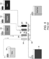
- FIG. 5 shows a set of printhead modules 34A, 34B, 34C, and 34D being positioned opposite printhead maintenance stations 36A, 36B, 36C, and 36D in a prior art inkjet printer.
- the trays in the printhead maintenance stations collect the purged ink and ink rinse fluid wiped from the faceplates of the printheads in the printhead modules as the maintenance procedure is performed on the printheads.
- the purged ink and ink rinse fluid is pumped from the printhead maintenance stations to the waste fluid reservoir 38.
- the printheads in each of the printhead modules 34A, 34B, 34C, and 34D are supplied with ink of an appropriate color from ink containers 32A, 32B, 32C, and 32D, respectively.
- a signal is generated to indicate that the exhausted ink supply container needs to be replaced with a new ink supply container. Additionally, when the waste fluid reservoir reaches a predetermined maximum level, a signal is generated so the waste fluid reservoir can be replaced with an empty waste fluid reservoir.
- the ink containers and the waste fluid reservoir are typically made of hard plastic so the disposal of these containers contributes to landfill issues and the like. Thus, inkjet printers would benefit from being able to treat waste ink in a manner that reduces the production of plastic waste by the printers.
- a color inkjet printer is configured to collect waste fluids in a manner that reduces the production of plastic waste by the printer.
- the color inkjet printer includes at least one printhead maintenance station configured to perform at least one purge cycle on at least one printhead in the inkjet printer to produce waste fluids; and at least one ink supply container having a bladder positioned within an internal volume of the ink supply container, the bladder being fluidly coupled to the printhead maintenance system to receive waste fluids from the printhead maintenance station.
- a method of operating a color inkjet printer collects waste fluids in a manner that reduces the production of plastic waste by the printer.
- the method includes performing at least one purge cycle on at least one printhead in the inkjet printer to produce waste fluids; and directing the waste fluids into at least one ink supply container having a bladder positioned within an internal volume of the ink supply container.
- An ink supply container is configured to collect waste fluids in a manner that reduces the production of plastic waste by the printer.
- the ink supply container includes a housing having an internal volume configured to hold a volume of ink; a bladder positioned within the internal volume of the housing; and an input connector on the housing, the input connector being configured to enable fluid to enter the bladder positioned within the housing.
- printer encompasses any apparatus that ejects ink drops onto different types of media to form ink images.
- FIG. 1 depicts a high-speed color inkjet printer 10 that uses newly configured ink containers to collect waste fluids produced by printhead maintenance stations to reduce the production of plastic waste by the inkjet printer.
- waste fluids means the fluids produced by performing printhead maintenance procedures on printheads in an inkjet printer. These waste fluids include but are not limited to faceplate rinse fluids and ink purged from the nozzles of a printhead.
- the printer 10 is a printer that directly forms an ink image on a surface of a media sheet stripped from one of the supplies of media sheets S 1 or S 2 and the sheets S are moved through the printer 10 by the controller 80 operating one or more of the actuators 40 that are operatively connected to rollers or to at least one driving roller of conveyor 52 that comprise a portion of the media transport 42 that passes through the print zone of the printer.
- each printhead module has only one printhead that has a width that corresponds to a width of the widest media in the cross-process direction that can be printed by the printer.
- the printhead modules have a plurality of printheads with each printhead having a width that is less than a width of the widest media in the cross-process direction that the printer can print.
- the printheads are arranged in an array of staggered printheads that enables media wider than a single printhead to be printed.
- the printheads within a module or between modules can also be interlaced so the density of the drops ejected by the printheads in the cross-process direction can be greater than the smallest spacing between the inkjets in a printhead in the cross-process direction.
- printer 10 is depicted with only two supplies of media sheets, the printer can be configured with three or more sheet supplies, each containing a different type or size of media.
- the printed image exits the print zone of printer 10 and passes under an image dryer 30 after the ink image is printed on a sheet S.
- the term "print zone" means an area of a media transport opposite the printheads of an inkjet printer.
- the image dryer 30 can include an infrared heater, a heated air blower, air returns, or combinations of these components to heat the ink image and at least partially fix an ink image to the sheet S.
- An infrared heater applies infrared heat to the printed image on the surface of the sheet S to evaporate water or solvent in the ink.
- the heated air blower directs heated air using a fan or other pressurized source of air over the ink to supplement the evaporation of the water or solvent from the ink.
- the air is then collected and evacuated by air returns to reduce the interference of the dryer air flow with other components in the printer.
- Controller 80 operates at least one of the actuators 40 to rotate a pivoting member at position 88 to either direct a sheet to receptacle 56 or to return path 72.
- a sheet S is moved by the rotation of rollers along the return path 72 in a direction opposite to the direction of movement in the process direction past the printheads.
- Pivoting member 82 is operated by the controller 80 to either direct the sheet along a curved portion of the return path 72 into inverter 76 so the sheet is turned over for duplex printing or along the straight portion of the return path 72. When the sheet follows the straight portion, the inverter 76 is bypassed and the side of the sheet previously printed can be printed again.
- the controller operates one of the actuators 40 to move the pivoting member 82 clockwise to direct a sheet into the inverter 76 and counterclockwise to bypass the inverter. Regardless of whether the substrate is inverted or not, it merges into the job stream being carried by the media transport 42 when controller 80 operates another actuator 40 to rotate pivoting member 86 to provide ingress of a sheet S from return path 72 to the job stream entering the print zone.
- the printed media sheets S not diverted to the duplex path 72 are carried by the media transport to the sheet receptacle 56 in which they are be collected. Before the printed sheets reach the receptacle 56, they pass by an optical sensor 84B.
- the optical sensor 84B generates image data of the printed sheets and this image data is analyzed by the controller 80 to detect streakiness in the printed images on the media sheets of a print job. Additionally, sheets that are printed with test pattern images are printed at intervals during the print job.
- Image data of these test pattern images generated by optical sensor 84B are analyzed by the controller 80 to determine which inkjets, if any, that were operated to eject ink into the test pattern did in fact do so, and if an inkjet did eject an ink drop whether the drop landed at its intended position with an appropriate mass. Any inkjet not ejecting an ink drop it was supposed to eject or ejecting a drop not having the correct mass or landing at an errant position is called an inoperative inkjet in this document.
- the controller can store data identifying the inoperative inkjets in database 92 operatively connected to the controller 80.
- RTMJ run-time missing inkjet
- the optical sensors 84A and 84B can be a digital camera, an array of LEDs and photodetectors, or other devices configured to generate image data of a passing surface. While FIG. 1 shows the printed sheets as being collected in the sheet receptacle 56, they can be directed to other processing stations (not shown) that perform tasks such as folding, collating, binding, and stapling of the media sheets.
- ESS controller or electronic subsystem
- the ESS or controller 80 is operatively connected to the components of the printhead modules 34A - 34D (and thus the printheads), the actuators 40, and the dryer 30.
- the ESS or controller 80 for example, is a self-contained computer having a central processor unit (CPU) with electronic data storage, and a display or user interface (UI) 50.
- the ESS or controller 80 for example, includes a sensor input and control circuit as well as a pixel placement and control circuit.
- the controller 80 reads, captures, prepares, and manages the image data flow between image input sources, such as a scanning system or an online or a work station connection (not shown), and the printhead modules 34A-34D.
- image input sources such as a scanning system or an online or a work station connection (not shown)
- the printhead modules 34A-34D are the main multi-tasking processor for operating and controlling all of the other machine subsystems and functions, including the printing process.
- the controller 80 can be implemented with general or specialized programmable processors that execute programmed instructions.
- the instructions and data required to perform the programmed functions can be stored in non-transitory computer readable medium associated with the processors or controllers.
- the processors, their memories, and interface circuitry configure the controllers to perform the operations described below. These components can be provided on a printed circuit card or provided as a circuit in an application specific integrated circuit (ASIC).
- ASIC application specific integrated circuit
- Each of the circuits can be implemented with a separate processor or multiple circuits can be implemented on the same processor.
- the circuits can be implemented with discrete components or circuits provided in very large scale integrated (VLSI) circuits.
- VLSI very large scale integrated
- the circuits described herein can be implemented with a combination of processors, ASICs, discrete components, or VLSI circuits.
- image content data for an image to be produced are sent to the controller 80 from either a scanning system or an online or work station connection for processing and generation of the printhead control signals output to the printhead modules 34A-34D.
- the controller receives print job parameters that identify the media weight, media dimensions, print speed, media type, ink area coverage to be produced on each side of each sheet, location of the image to be produced on each side of each sheet, media color, media fiber orientation for fibrous media, print zone temperature and humidity, media moisture content, and media manufacturer.
- print job parameters means non-image content data for a print job and the term “image content data” means digital data that identifies an ink image to be printed on a media sheet.
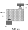
- FIG. 2A shows a cross-sectional view of an ink supply container 204 that includes a bladder 212 and a connection 216 that enables the bladder to be filled with waste fluids as the ink supply 208 within the container is depleted.
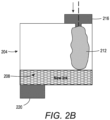
- FIG. 2B is a cross-sectional view of the ink supply container 204 after the ink supply 208 has been nearly emptied and the bladder has expanded as the ink level lowers and the bladder is filled with waste fluids.
- the bladder 212 is made of polymeric material that is flexible so the volume within the bladder increases as it is filled with waste fluids and the volume of ink occupying the internal cavity of the ink supply container decreases.
- the bladder hangs from the input connection without any supporting structure within the internal volume of the ink supply container.
- the housing of the ink container 204 is a hard plastic bottle or container as known in the art. Hard plastics include, but are not limited to, acetals, acrylic, polyimides, glass epoxies, thermoset plastics, high impact polystyrene, poly carbonate, poly vinyl chloride, and the like.
- the term "bladder” means a flexible member having an internal volume configured to be fluidly connected to a source of incoming fluid.
- the flexible bladder can be made of a high-density polyethylene (HDPE) material.
- the thickness of the bladder wall ranges from 75 to 300 microns to adequately prevent waste fluid leaks and still provide bladder flexibility.
- Other choices for bladder material are polypropylene (PP) or linear low-density polyethylene (LLDPE) using a similar wall thickness to prevent leaks and still be flexible. While the materials are flexible, they are not expandable to form an increasingly large volume. Instead, the expandable bladder has a predetermined volume that can be accommodated by the internal volume of the ink supply container. Bio plastics are not good materials for bladders as their ability to resist being compromised by the chemicals in the various inks used in inkjet printing is unknown.
- the bladder is installed within the internal volume of an ink supply container in a folded or rolled configuration. As the ink volume in the container drops, the bladder unfolds or unrolls to provide a volume within the bladder that can be filled with waste fluids. Thus, the bladder and the waste fluids within the bladder are supported by the ink within the ink supply container until the bladder end reaches the floor of the ink supply container.
- the ink output port and the bladder input port can be sized differently to help ensure that the bladder input port is not connected to an ink input port for a printhead and to prevent a waste fluid conduit being connected to the ink output port of an ink supply container.
- waste fluid input port and the ink output port can be positioned on different sides of the ink supply container to facilitate distinguishing the two ports at the time of ink supply container installation and removal. Additionally, one way valves or no-drip shutoff values can be included in the input and output ports of an ink supply container to ensure that no ink or waste fluid drips occur during installation or removal of an ink supply container.
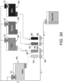
- each of the ink supply containers 32A, 32B, 32C, and 32D have been configured as the ink supply container 204 described with reference to FIG. 2A and FIG. 2B to include a bladder 212 and a bladder connector 216.
- no waste fluid container 38 as shown in the prior art ink supply system of FIG. 5 has been included. Instead, the waste fluid outputs of the printhead maintenance stations 36A, 36B, 36C, and 36D have been serially connected together in a single conduit that is fluidly connected to each of the bladder connections for ink supply containers 32A, 32B, 32C, and 32D.
- waste fluids flow through this conduit, they arrive first at the bladder connector 216 of the ink supply container 32A to fill the bladder 212 of this container.
- the bladder 212 fills it expands but begins to approach the capacity of its internal volume increasing the pressure against flow into the bladder. Consequently, more of the volume of waste fluids flowing through the conduit begin to migrate to the bladder connector 216 for the bladder 212 in ink supply container 32B.
- This sequential filling of the bladders 212 in the ink supply containers 32A, 32B, 32C, and 32D continues until an ink supply container is exhausted of supply ink and is replaced. In this manner, the capacity of the bladders in the ink supply containers for waste fluids is replenished.
- FIG. 3B differs from the configuration shown in FIG. 3A because the waste fluid outputs of the printhead maintenance stations 36A, 36B, 36C, and 36D have been connected in parallel to the bladder connections for ink supply containers 32A, 32B, 32C, and 32D, respectively.
- each of the ink supply containers 32A, 32B, 32C, and 32D have been configured as the ink supply container 204 of FIG. 2A to include a bladder 212 and a bladder connector 216 and, no waste fluid container 38 as shown in the prior art ink supply system of FIG. 5 has been included.
- the waste fluid reservoir 38 has been eliminated so the plastic waste produced when the reservoir is filled and replaced is also eliminated.
- each printhead maintenance station As the waste fluids flow from each printhead maintenance station to the respective ink supply container, they enter the bladders 212 of the respective ink supply containers. As the bladders 212 fill, they expand but printing operations deplete the ink supplies 208 within the ink supply containers at a faster rate than the printhead maintenance units produce waste fluid for the bladders. This parallel filling of the bladders 212 in the ink supply containers 32A, 32B, 32C, and 32D continues until an ink supply container is exhausted of supply ink and is replaced. In this manner, the capacity of the bladders in the ink supply containers for waste fluids is replenished.
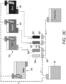
- each of the ink supply containers 32A, 32B, 32C, and 32D have been configured as the ink supply container 204 in FIG. 2A to include a bladder 212 and a bladder connector 216.
- a waste fluid container 38 as shown in the prior art ink supply system of FIG. 5 has been retained.
- the waste fluid outputs of the printhead maintenance stations 36A, 36B, 36C, and 36D have been serially connected together into a single conduit that is fluidly connected to the waste fluid reservoir 38 so the waste fluid reservoir receives the combined waste fluid flow from the printhead maintenance stations.
- a pneumatic device connected to the output port of the waste fluid reservoir is activated to pump waste fluid from the waste fluid reservoir 38 to the serially connected bladder connectors 216 for ink supply containers 32A, 32B, 32C, and 32D.
- the waste fluids flow to the serially connected bladder connectors, they arrive first at the bladder connector 216 of the ink supply container 32A to fill the bladder 212 of this container.
- the bladder 212 fills it expands but begins to approach the capacity of its internal volume increasing the pressure against flow into the bladder. Consequently, more of the volume of waste fluids flowing through the conduit begin to migrate to the bladder connector 216 for the bladder 212 in ink supply container 32B.
- a fluid level sensor is configured to generate a signal indicative of the fluid level within the waste fluid reservoir and a controller, such as controller 80, is operatively connected to the fluid level sensor and the pneumatic device and is configured to receive the signal from the fluid level sensor to detect when the predetermined level is reached and operate the pneumatic device.
- the pneumatic device is a pump.
- FIG. 4 A process 400 for operating the inkjet printer of FIG. 1 to reduce the production of plastic waste by the printer is shown in FIG. 4 .
- statements that the process is performing some task or function refers to a controller or general purpose processor executing programmed instructions stored in non-transitory computer readable medium operatively connected to the controller or processor to manipulate data or to operate one or more components in the printer to perform the task or function.
- the controller 80 noted above can be such a controller or processor.
- the controller can be implemented with more than one processor and associated circuitry and components, each of which is configured to perform one or more tasks or functions described herein.
- the steps of the method may be performed in any feasible chronological order, regardless of the order shown in the figures or the order in which the processing is described.
- the process 400 of FIG. 4 begins by detecting the return of at least one printhead module to its printing position after at least one purge cycle has been performed on at least one printhead in the at least one printhead module (block 404). If one is detected, then the pneumatic device 208 connected to a waste ink receptacle within a printhead maintenance station is activated and waste fluids are moved from the printhead maintenance stations to one or more bladders in the ink supply containers (block 408).
- waste fluids can flow together in a single conduit to the serially connected bladder connectors of the ink supply containers or flow in parallel to the bladder connectors of the ink supply containers respectively connected to the printhead maintenance stations or flow to a waste fluid reservoir before being removed from the waste fluid reservoir and sent to the serially connected bladder connections of the ink supply containers. If no return of a printhead module is detected (block 404), then the process determines if depletion of an ink supply container is detected (block 412). If an exhausted ink supply container is detected, then the depleted ink supply container is replaced and the capacity of the waste fluid system is replenished (block 416).
- the process continues checking for the end of printhead module maintenance cycles and depleted ink supply containers indefinitely in printers in which the printhead maintenance stations are connected to the bladder connectors of ink supply containers serially or in parallel. In the configuration having a waste fluid reservoir, the process continues until the operational life of the waste fluid reservoir is reached and the reservoir is replaced.
Landscapes
- Engineering & Computer Science (AREA)
- Manufacturing & Machinery (AREA)
- Environmental & Geological Engineering (AREA)
- Ink Jet (AREA)
Abstract
An inkjet printer uses ink supply containers that includes bladders for holding waste fluids produced by printhead maintenance stations. The bladders are connected serially or in parallel to the output ports of the printhead maintenance stations to store waste fluids within the bladders of the ink supply containers. As the ink supply containers are depleted of their supply ink, they are replaced and new ink supply containers having bladders within them are installed to renew the capacity of the printer to store waste fluids. In two embodiments, the need for a waste fluid reservoir is eliminated and in a third embodiment, the operational life of a waste fluid reservoir is extended. In all of these embodiments, the production of plastic waste by the printer is reduced.
Description
- This disclosure relates generally to devices that produce ink images on media, and more particularly, to the reducing of plastic waste produced by such printers.
- Inkjet imaging devices, also known as inkjet printers, eject liquid ink from printheads to form images on an image receiving surface. The printheads include a plurality of inkjets that are arranged in an array. Each inkjet has a thermal or piezoelectric actuator that is coupled to a printhead controller. The printhead controller generates firing signals that correspond to digital data content that define the images. The actuators in the printheads respond to the firing signals by expanding into an ink chamber fluidly connected to a nozzle to eject ink drops from the nozzle onto an image receiving surface to form an ink image that corresponds to the digital image content used to generate the firing signals. The image receiving surface is usually a continuous web of media material or a series of media sheets.
- Inkjet printers used for producing color images typically include multiple printhead modules. Each printhead module includes one or more printheads that typically eject a single color of ink. In a typical inkjet color printer, four printhead modules are positioned in a process direction with each printhead module ejecting a different color of ink. The four ink colors most frequently used are cyan, magenta, yellow, and black. The common nomenclature for such printers is CMYK color printers. Some CMYK color printers have two printhead modules that print each color of ink. The printhead modules that print the same color of ink are offset from each other by one-half of the distance between adjacent inkjets in the cross-process direction to double the number of pixels per inch to increase the density of a line of the color of ink ejected by the printheads in the two modules. As used in this document, the term "process direction" means the direction of movement of the image receiving surface as it passes the printheads in the printer and the term "cross-process direction" means a direction that is perpendicular to the process direction in the plane of the image receiving surface.
- Inkjets, especially those in printheads that eject aqueous inks, need to fire regularly to help prevent the ink in the nozzles from drying. Sometimes the nozzles in a printhead dry because the inkjets have ejected a substantial amount of ink to form high coverage areas in an ink image. The operation of a high proportion of inkjets in a portion of the faceplate on the printhead can produce a high number of satellite drops that tend to adhere to the faceplate. Satellite drops are small ink drops that separate from the larger drops that travel from the nozzles to the image receiving substrates. The buildup of these satellite drops on a faceplate can clog nozzles in the faceplate. Additionally, if the inkjets in a printhead are not operated frequently enough, such as when low ink area coverage image portions are printed, then the ink within an inkjet can dry and render the inkjet inoperative. To maintain the operational status of the inkjets, the printhead modules are moved from positions opposite the path of the image receiving substrates to printhead maintenance stations where the printheads are purged. Purging a printhead means a pressurized gas or liquid is applied to the ink supply chambers within a printhead to force ink from the chamber into the nozzles where the ink is emitted from the nozzles onto the faceplate. One or more wipers are then moved across the faceplate to remove the purged ink from the faceplate into a waste ink receptacle.
- Treatment of the waste ink can present environmental issues.
FIG. 5 shows a set ofprinthead modules printhead maintenance stations waste fluid reservoir 38. The printheads in each of theprinthead modules ink containers - A color inkjet printer is configured to collect waste fluids in a manner that reduces the production of plastic waste by the printer. The color inkjet printer includes at least one printhead maintenance station configured to perform at least one purge cycle on at least one printhead in the inkjet printer to produce waste fluids; and at least one ink supply container having a bladder positioned within an internal volume of the ink supply container, the bladder being fluidly coupled to the printhead maintenance system to receive waste fluids from the printhead maintenance station.
- A method of operating a color inkjet printer collects waste fluids in a manner that reduces the production of plastic waste by the printer. The method includes performing at least one purge cycle on at least one printhead in the inkjet printer to produce waste fluids; and directing the waste fluids into at least one ink supply container having a bladder positioned within an internal volume of the ink supply container.
- An ink supply container is configured to collect waste fluids in a manner that reduces the production of plastic waste by the printer. The ink supply container includes a housing having an internal volume configured to hold a volume of ink; a bladder positioned within the internal volume of the housing; and an input connector on the housing, the input connector being configured to enable fluid to enter the bladder positioned within the housing.
- The foregoing aspects and other features of a color inkjet printer, color inkjet printer operational method, and ink supply container that reduces the plastic waste produced by an inkjet printer are explained in the following description, taken in connection with the accompanying drawings.
-
FIG. 1 is a schematic drawing of a color inkjet printer that collects waste fluids in a manner that reduces the production of plastic waste by the inkjet printer. -
FIG. 2A is a cross-sectional view of a new ink supply container that includes a waste fluid bladder when the container is installed andFIG. 2B is a cross-sectional view of the ink container when the ink supply container is near depletion. -
FIG. 3A shows serial fluid connections between the printhead maintenance stations in the inkjet printer ofFIG. 1 to ink supply containers configured as shown inFIG. 2A andFIG. 2B . -
FIG. 3B shows parallel fluid connections between the printhead maintenance stations in the inkjet printer ofFIG. 1 to ink supply containers configured as shown inFIG. 2A andFIG. 2B . -
FIG. 3C shows serial fluid connections between the printhead maintenance stations in the inkjet printer ofFIG. 1 to a waste fluid reservoir and serial connections from the waste ink reservoir to the ink supply containers configured as shown inFIG. 2A andFIG. 2B . -
FIG. 4 is a flow diagram for operating the inkjet printer ofFIG. 1 . -
FIG. 5 shows the collection of waste fluids in a prior art inkjet printer. - For a general understanding of the environment for the printer and the printer operational method disclosed herein as well as the details for the printer and the printer operational method, reference is made to the drawings. In the drawings, like reference numerals have been used throughout to designate like elements. As used herein, the word "printer" encompasses any apparatus that ejects ink drops onto different types of media to form ink images.
-
FIG. 1 depicts a high-speedcolor inkjet printer 10 that uses newly configured ink containers to collect waste fluids produced by printhead maintenance stations to reduce the production of plastic waste by the inkjet printer. As used in this document, the term "waste fluids" means the fluids produced by performing printhead maintenance procedures on printheads in an inkjet printer. These waste fluids include but are not limited to faceplate rinse fluids and ink purged from the nozzles of a printhead. As illustrated, theprinter 10 is a printer that directly forms an ink image on a surface of a media sheet stripped from one of the supplies of media sheets S1 or S2 and the sheets S are moved through theprinter 10 by thecontroller 80 operating one or more of theactuators 40 that are operatively connected to rollers or to at least one driving roller ofconveyor 52 that comprise a portion of themedia transport 42 that passes through the print zone of the printer. In one embodiment, each printhead module has only one printhead that has a width that corresponds to a width of the widest media in the cross-process direction that can be printed by the printer. In other embodiments, the printhead modules have a plurality of printheads with each printhead having a width that is less than a width of the widest media in the cross-process direction that the printer can print. In these modules, the printheads are arranged in an array of staggered printheads that enables media wider than a single printhead to be printed. Additionally, the printheads within a module or between modules can also be interlaced so the density of the drops ejected by the printheads in the cross-process direction can be greater than the smallest spacing between the inkjets in a printhead in the cross-process direction. Althoughprinter 10 is depicted with only two supplies of media sheets, the printer can be configured with three or more sheet supplies, each containing a different type or size of media. - With further reference to
FIG. 1 , the printed image exits the print zone ofprinter 10 and passes under animage dryer 30 after the ink image is printed on a sheet S. As used in this document, the term "print zone" means an area of a media transport opposite the printheads of an inkjet printer. Theimage dryer 30 can include an infrared heater, a heated air blower, air returns, or combinations of these components to heat the ink image and at least partially fix an ink image to the sheet S. An infrared heater applies infrared heat to the printed image on the surface of the sheet S to evaporate water or solvent in the ink. The heated air blower directs heated air using a fan or other pressurized source of air over the ink to supplement the evaporation of the water or solvent from the ink. The air is then collected and evacuated by air returns to reduce the interference of the dryer air flow with other components in the printer. -
Controller 80 operates at least one of theactuators 40 to rotate a pivoting member atposition 88 to either direct a sheet to receptacle 56 or to returnpath 72. A sheet S is moved by the rotation of rollers along thereturn path 72 in a direction opposite to the direction of movement in the process direction past the printheads. Pivotingmember 82 is operated by thecontroller 80 to either direct the sheet along a curved portion of thereturn path 72 intoinverter 76 so the sheet is turned over for duplex printing or along the straight portion of thereturn path 72. When the sheet follows the straight portion, theinverter 76 is bypassed and the side of the sheet previously printed can be printed again. The controller operates one of theactuators 40 to move the pivotingmember 82 clockwise to direct a sheet into theinverter 76 and counterclockwise to bypass the inverter. Regardless of whether the substrate is inverted or not, it merges into the job stream being carried by themedia transport 42 whencontroller 80 operates anotheractuator 40 to rotate pivotingmember 86 to provide ingress of a sheet S fromreturn path 72 to the job stream entering the print zone. - As further shown in
FIG. 1 , the printed media sheets S not diverted to theduplex path 72 are carried by the media transport to thesheet receptacle 56 in which they are be collected. Before the printed sheets reach thereceptacle 56, they pass by anoptical sensor 84B. Theoptical sensor 84B generates image data of the printed sheets and this image data is analyzed by thecontroller 80 to detect streakiness in the printed images on the media sheets of a print job. Additionally, sheets that are printed with test pattern images are printed at intervals during the print job. Image data of these test pattern images generated byoptical sensor 84B are analyzed by thecontroller 80 to determine which inkjets, if any, that were operated to eject ink into the test pattern did in fact do so, and if an inkjet did eject an ink drop whether the drop landed at its intended position with an appropriate mass. Any inkjet not ejecting an ink drop it was supposed to eject or ejecting a drop not having the correct mass or landing at an errant position is called an inoperative inkjet in this document. The controller can store data identifying the inoperative inkjets indatabase 92 operatively connected to thecontroller 80. These sheets printed with the test patterns are sometimes called run-time missing inkjet (RTMJ) sheets and these sheets are discarded from the output of the print job. A user can operate theuser interface 50 to obtain reports displayed on the interface that identify the number of inoperative inkjets and the printheads in which the inoperative inkjets are located. For sheets that are not inverted and merged into the job stream by the operation of pivotingmember 86,optical sensor 84A generates image data of the printed side and thecontroller 80 uses that image data to register the sheets and to operate the ejectors in the printhead to further print images on the previously printed sheet sides. Theoptical sensors FIG. 1 shows the printed sheets as being collected in thesheet receptacle 56, they can be directed to other processing stations (not shown) that perform tasks such as folding, collating, binding, and stapling of the media sheets. - Operation and control of the various subsystems, components and functions of the machine or
printer 10 are performed with the aid of a controller or electronic subsystem (ESS) 80. The ESS orcontroller 80 is operatively connected to the components of theprinthead modules 34A - 34D (and thus the printheads), theactuators 40, and thedryer 30. The ESS orcontroller 80, for example, is a self-contained computer having a central processor unit (CPU) with electronic data storage, and a display or user interface (UI) 50. The ESS orcontroller 80, for example, includes a sensor input and control circuit as well as a pixel placement and control circuit. In addition, thecontroller 80 reads, captures, prepares, and manages the image data flow between image input sources, such as a scanning system or an online or a work station connection (not shown), and theprinthead modules 34A-34D. As such, the ESS orcontroller 80 is the main multi-tasking processor for operating and controlling all of the other machine subsystems and functions, including the printing process. - The
controller 80 can be implemented with general or specialized programmable processors that execute programmed instructions. The instructions and data required to perform the programmed functions can be stored in non-transitory computer readable medium associated with the processors or controllers. The processors, their memories, and interface circuitry configure the controllers to perform the operations described below. These components can be provided on a printed circuit card or provided as a circuit in an application specific integrated circuit (ASIC). Each of the circuits can be implemented with a separate processor or multiple circuits can be implemented on the same processor. Alternatively, the circuits can be implemented with discrete components or circuits provided in very large scale integrated (VLSI) circuits. Also, the circuits described herein can be implemented with a combination of processors, ASICs, discrete components, or VLSI circuits. - In operation, image content data for an image to be produced are sent to the
controller 80 from either a scanning system or an online or work station connection for processing and generation of the printhead control signals output to theprinthead modules 34A-34D. Along with the image content data, the controller receives print job parameters that identify the media weight, media dimensions, print speed, media type, ink area coverage to be produced on each side of each sheet, location of the image to be produced on each side of each sheet, media color, media fiber orientation for fibrous media, print zone temperature and humidity, media moisture content, and media manufacturer. As used in this document, the term "print job parameters" means non-image content data for a print job and the term "image content data" means digital data that identifies an ink image to be printed on a media sheet. -
FIG. 2A shows a cross-sectional view of anink supply container 204 that includes abladder 212 and aconnection 216 that enables the bladder to be filled with waste fluids as theink supply 208 within the container is depleted. Three different connection configurations are described below with reference toFIG. 3A ,FIG. 3B , andFIG. 3C for moving waste fluids into thebladder 212 of anink supply container 204.FIG. 2B is a cross-sectional view of theink supply container 204 after theink supply 208 has been nearly emptied and the bladder has expanded as the ink level lowers and the bladder is filled with waste fluids. Thebladder 212 is made of polymeric material that is flexible so the volume within the bladder increases as it is filled with waste fluids and the volume of ink occupying the internal cavity of the ink supply container decreases. The bladder hangs from the input connection without any supporting structure within the internal volume of the ink supply container. The housing of theink container 204 is a hard plastic bottle or container as known in the art. Hard plastics include, but are not limited to, acetals, acrylic, polyimides, glass epoxies, thermoset plastics, high impact polystyrene, poly carbonate, poly vinyl chloride, and the like. As used in this document, the term "bladder" means a flexible member having an internal volume configured to be fluidly connected to a source of incoming fluid. The flexible bladder can be made of a high-density polyethylene (HDPE) material. The thickness of the bladder wall ranges from 75 to 300 microns to adequately prevent waste fluid leaks and still provide bladder flexibility. Other choices for bladder material are polypropylene (PP) or linear low-density polyethylene (LLDPE) using a similar wall thickness to prevent leaks and still be flexible. While the materials are flexible, they are not expandable to form an increasingly large volume. Instead, the expandable bladder has a predetermined volume that can be accommodated by the internal volume of the ink supply container. Bio plastics are not good materials for bladders as their ability to resist being compromised by the chemicals in the various inks used in inkjet printing is unknown. - The bladder is installed within the internal volume of an ink supply container in a folded or rolled configuration. As the ink volume in the container drops, the bladder unfolds or unrolls to provide a volume within the bladder that can be filled with waste fluids. Thus, the bladder and the waste fluids within the bladder are supported by the ink within the ink supply container until the bladder end reaches the floor of the ink supply container. The ink output port and the bladder input port can be sized differently to help ensure that the bladder input port is not connected to an ink input port for a printhead and to prevent a waste fluid conduit being connected to the ink output port of an ink supply container. Additionally, the waste fluid input port and the ink output port can be positioned on different sides of the ink supply container to facilitate distinguishing the two ports at the time of ink supply container installation and removal. Additionally, one way valves or no-drip shutoff values can be included in the input and output ports of an ink supply container to ensure that no ink or waste fluid drips occur during installation or removal of an ink supply container.
- In the configuration shown in
FIG. 3A , each of theink supply containers ink supply container 204 described with reference toFIG. 2A andFIG. 2B to include abladder 212 and abladder connector 216. InFIG. 3A , nowaste fluid container 38 as shown in the prior art ink supply system ofFIG. 5 has been included. Instead, the waste fluid outputs of theprinthead maintenance stations ink supply containers bladder connector 216 of theink supply container 32A to fill thebladder 212 of this container. As thebladder 212 fills it expands but begins to approach the capacity of its internal volume increasing the pressure against flow into the bladder. Consequently, more of the volume of waste fluids flowing through the conduit begin to migrate to thebladder connector 216 for thebladder 212 inink supply container 32B. This sequential filling of thebladders 212 in theink supply containers - The configuration shown in
FIG. 3B differs from the configuration shown inFIG. 3A because the waste fluid outputs of theprinthead maintenance stations ink supply containers ink supply containers ink supply container 204 ofFIG. 2A to include abladder 212 and abladder connector 216 and, nowaste fluid container 38 as shown in the prior art ink supply system ofFIG. 5 has been included. Thus, in the configurations shown inFIG. 3A andFIG. 3B , thewaste fluid reservoir 38 has been eliminated so the plastic waste produced when the reservoir is filled and replaced is also eliminated. As the waste fluids flow from each printhead maintenance station to the respective ink supply container, they enter thebladders 212 of the respective ink supply containers. As thebladders 212 fill, they expand but printing operations deplete the ink supplies 208 within the ink supply containers at a faster rate than the printhead maintenance units produce waste fluid for the bladders. This parallel filling of thebladders 212 in theink supply containers - In the configuration shown in
FIG. 3C , each of theink supply containers ink supply container 204 inFIG. 2A to include abladder 212 and abladder connector 216. InFIG. 3C , however, awaste fluid container 38 as shown in the prior art ink supply system ofFIG. 5 has been retained. Again, the waste fluid outputs of theprinthead maintenance stations waste fluid reservoir 38 so the waste fluid reservoir receives the combined waste fluid flow from the printhead maintenance stations. Either on a periodic time basis or upon detection of the waste fluid within the waste fluid reservoir reaching a predetermined level, a pneumatic device connected to the output port of the waste fluid reservoir is activated to pump waste fluid from thewaste fluid reservoir 38 to the serially connectedbladder connectors 216 forink supply containers bladder connector 216 of theink supply container 32A to fill thebladder 212 of this container. As thebladder 212 fills it expands but begins to approach the capacity of its internal volume increasing the pressure against flow into the bladder. Consequently, more of the volume of waste fluids flowing through the conduit begin to migrate to thebladder connector 216 for thebladder 212 inink supply container 32B. This sequential filling of thebladders 212 in theink supply containers controller 80, is operatively connected to the fluid level sensor and the pneumatic device and is configured to receive the signal from the fluid level sensor to detect when the predetermined level is reached and operate the pneumatic device. In one embodiment, the pneumatic device is a pump. - A
process 400 for operating the inkjet printer ofFIG. 1 to reduce the production of plastic waste by the printer is shown inFIG. 4 . In the description of the process, statements that the process is performing some task or function refers to a controller or general purpose processor executing programmed instructions stored in non-transitory computer readable medium operatively connected to the controller or processor to manipulate data or to operate one or more components in the printer to perform the task or function. Thecontroller 80 noted above can be such a controller or processor. Alternatively, the controller can be implemented with more than one processor and associated circuitry and components, each of which is configured to perform one or more tasks or functions described herein. Additionally, the steps of the method may be performed in any feasible chronological order, regardless of the order shown in the figures or the order in which the processing is described. - The
process 400 ofFIG. 4 begins by detecting the return of at least one printhead module to its printing position after at least one purge cycle has been performed on at least one printhead in the at least one printhead module (block 404). If one is detected, then thepneumatic device 208 connected to a waste ink receptacle within a printhead maintenance station is activated and waste fluids are moved from the printhead maintenance stations to one or more bladders in the ink supply containers (block 408). As noted previously, these waste fluids can flow together in a single conduit to the serially connected bladder connectors of the ink supply containers or flow in parallel to the bladder connectors of the ink supply containers respectively connected to the printhead maintenance stations or flow to a waste fluid reservoir before being removed from the waste fluid reservoir and sent to the serially connected bladder connections of the ink supply containers. If no return of a printhead module is detected (block 404), then the process determines if depletion of an ink supply container is detected (block 412). If an exhausted ink supply container is detected, then the depleted ink supply container is replaced and the capacity of the waste fluid system is replenished (block 416). The process continues checking for the end of printhead module maintenance cycles and depleted ink supply containers indefinitely in printers in which the printhead maintenance stations are connected to the bladder connectors of ink supply containers serially or in parallel. In the configuration having a waste fluid reservoir, the process continues until the operational life of the waste fluid reservoir is reached and the reservoir is replaced. - It will be appreciated that variants of the above-disclosed and other features, and functions, or alternatives thereof, may be desirably combined into many other different systems or applications. Various presently unforeseen or unanticipated alternatives, modifications, variations, or improvements therein may be subsequently made by those skilled in the art, which are also intended to be encompassed by the following claims.
Claims (15)
- An inkjet printer comprising:at least one printhead maintenance station configured to perform at least one purge cycle on at least one printhead in the inkjet printer to produce waste fluids; andat least one ink supply container having a bladder positioned within an internal volume of the ink supply container, the bladder being fluidly coupled to the printhead maintenance system to receive waste fluids from the printhead maintenance station.
- The inkjet printer of claim 1 further comprising:
a plurality of ink supply containers, each ink supply container having a bladder positioned with the internal volume of the ink supply container, an input of each bladder in the ink supply containers in the plurality of ink supply containers being fluidly connected to one another and the at least one printhead maintenance station. - The inkjet printer of claim 2 further comprising:a waste fluid reservoir that is fluidly connected to the at least one printhead maintenance station and the inputs of the bladders in the plurality of ink supply containers, the waste fluid reservoir being configured to receive waste fluids from the at least one printhead maintenance station and send the waste fluids from the waste fluid reservoir to at least one of the inputs of the bladders in the plurality of ink supply containers;optionally further comprising:a pneumatic device configured to move waste fluids out of the waste fluid reservoir;optionally further comprising:
a controller operatively connected to the pneumatic device such as a pump, the controller being configured to operate the pneumatic device on a timed periodic basis to move waste fluids from the waste fluid reservoir to the at least one input of the bladders in the ink supply containers. - The inkjet printer of claim 3 further comprising:a fluid level detector configured to generate a signal indicative of a fluid level within the waste fluid reservoir; anda controller operatively connected to the fluid level detector and the pneumatic device, the controller being configured to operate the pneumatic device when the fluid level detector generates a signal indicating the fluid level has reached a predetermined level.
- The inkjet printer of claim 3 wherein the bladder, for example consisting essentially of a flexible polymeric material, hangs from the input to the bladder within the internal volume of the ink supply container in which the bladder is located without supporting structure within the volume of the ink supply container.
- The inkjet printer of claim 1 further comprising:a plurality of printhead maintenance stations; anda plurality of ink supply containers, each ink supply container having a bladder positioned with the internal volume of the ink supply container, an input of each bladder in the ink supply containers in the plurality of ink supply containers being fluidly connected to only one of the printhead maintenance stations in the plurality of printhead maintenance stations.
- A method of operating an inkjet printer comprising:performing at least one purge cycle on at least one printhead in the inkjet printer to produce waste fluids; anddirecting the waste fluids into at least one ink supply container having a bladder positioned within an internal volume of the ink supply container.
- The method of claim 7 further comprising:directing the waste fluids into a plurality of bladders in a plurality of ink supply containers, each ink supply container having the bladder positioned with the internal volume of the ink supply container, an input of each bladder in the ink supply containers in the plurality of ink supply containers being fluidly connected to one another;optionally further comprising:receiving the waste fluids in a waste fluid reservoir before directing the waste fluids to the input of each bladder in the ink supply containers in the plurality of ink supply containers;optionally further comprising:
operating a pneumatic device to move waste fluids out of the waste fluid reservoir into the plurality of bladders in the plurality of ink supply containers. - The method of claim 8 wherein the pneumatic device is operated on a timed periodic basis; or
wherein the method further comprises:generating a signal indicative of a fluid level within the waste fluid reservoir; andoperating the pneumatic device when the generated signal indicates the fluid level has reached a predetermined level. - The method of claim 7 further comprising:
directing waste fluids from a plurality of printhead maintenance stations into a plurality of bladders, each bladder in the plurality of bladders being positioned within an ink supply container in a plurality of ink supply containers, each printhead maintenance station in the plurality of printhead maintenance stations being fluidly connected to only one bladder in the plurality of bladders in a one-to-one correspondence. - An ink supply container for use in an inkjet printer comprising:a housing having an internal volume configured to hold a volume of ink;a bladder positioned within the internal volume of the housing; andan input connector on the housing, the input connector being configured to enable fluid to enter the bladder positioned within the housing.
- The ink supply container of claim 11 wherein the housing consists essentially of hard plastic such as acetal, acrylic, polyimide, glass epoxy, thermoset plastic, high impact polystyrene, poly carbonate, or poly vinyl chloride;
optionally wherein the bladder consists essentially of a flexible polymeric material such as high-density polyethylene (HDPE), polypropylene (PP), or linear low-density polyethylene (LLDPE); further optionally wherein a thickness of the flexible polymeric material is within a range of 75 to 300 microns. - The ink supply container of claim 12 wherein the bladder hangs from the input connection without supporting structure within the internal volume of the housing.
- The ink supply container of claim 13 wherein the bladder unrolls as the volume of ink within the housing decreases or wherein the bladder unfolds as the volume of ink within the housing decreases.
- The ink supply container of claim 11, the input connector further comprising:
a no-drip shutoff valve or a one way valve.
Applications Claiming Priority (1)
| Application Number | Priority Date | Filing Date | Title |
|---|---|---|---|
| US18/462,790 US12472747B2 (en) | 2023-09-07 | 2023-09-07 | System and method for reducing plastic waste in inkjet printers |
Publications (1)
| Publication Number | Publication Date |
|---|---|
| EP4520536A1 true EP4520536A1 (en) | 2025-03-12 |
Family
ID=92409005
Family Applications (1)
| Application Number | Title | Priority Date | Filing Date |
|---|---|---|---|
| EP24194355.4A Pending EP4520536A1 (en) | 2023-09-07 | 2024-08-13 | System and method for reducing plastic waste in inkjet printers |
Country Status (3)
| Country | Link |
|---|---|
| US (1) | US12472747B2 (en) |
| EP (1) | EP4520536A1 (en) |
| JP (1) | JP2025038877A (en) |
Citations (4)
| Publication number | Priority date | Publication date | Assignee | Title |
|---|---|---|---|---|
| US20070008372A1 (en) * | 2005-07-08 | 2007-01-11 | Fuji Photo Film Co., Ltd. | Ink cartridge, ink jet recording apparatus and waste-ink cartridge |
| JP2010089379A (en) * | 2008-10-08 | 2010-04-22 | Canon Inc | Inkjet recording device |
| US20130335481A1 (en) * | 2012-06-18 | 2013-12-19 | Ricoh Company, Ltd. | Ink cartridge and image forming apparatus |
| US20170253043A1 (en) * | 2015-03-06 | 2017-09-07 | Hewlett-Packard Development Company, L.P. | Printing fluid container |
Family Cites Families (8)
| Publication number | Priority date | Publication date | Assignee | Title |
|---|---|---|---|---|
| DE68920262T3 (en) | 1988-10-14 | 2000-11-16 | Seiko Epson Corp., Tokio/Tokyo | Ink cartridge for an inkjet printer. |
| GB2242867B (en) | 1990-02-15 | 1994-04-13 | Canon Kk | Waste ink receiving cartridge and ink recording apparatus using said cartridge |
| JP3115660B2 (en) * | 1990-12-07 | 2000-12-11 | キヤノン株式会社 | Ink jet head cartridge and ink tank cartridge using decomposable plastic as a part of the structure, and an ink jet apparatus having a mounting portion for mounting these cartridges |
| JP2752793B2 (en) | 1990-12-10 | 1998-05-18 | キヤノン株式会社 | Ink jet recording apparatus and ink tank cartridge for the apparatus |
| DE69315870T2 (en) * | 1992-03-13 | 1998-05-20 | Canon Kk | Ink tank |
| DE69801207T2 (en) | 1997-08-28 | 2002-04-18 | Seiko Epson Corp., Tokio/Tokyo | INK TANK WITH WASTE INK ABSORPTION FUNCTION |
| EP1308300A1 (en) * | 2001-10-31 | 2003-05-07 | Hewlett Packard Company, a Delaware Corporation | Ink condensate removal in hardcopy apparatus |
| JP2014047305A (en) * | 2012-08-31 | 2014-03-17 | Fujifilm Corp | Ink pack |
-
2023
- 2023-09-07 US US18/462,790 patent/US12472747B2/en active Active
-
2024
- 2024-08-13 EP EP24194355.4A patent/EP4520536A1/en active Pending
- 2024-08-22 JP JP2024140576A patent/JP2025038877A/en active Pending
Patent Citations (4)
| Publication number | Priority date | Publication date | Assignee | Title |
|---|---|---|---|---|
| US20070008372A1 (en) * | 2005-07-08 | 2007-01-11 | Fuji Photo Film Co., Ltd. | Ink cartridge, ink jet recording apparatus and waste-ink cartridge |
| JP2010089379A (en) * | 2008-10-08 | 2010-04-22 | Canon Inc | Inkjet recording device |
| US20130335481A1 (en) * | 2012-06-18 | 2013-12-19 | Ricoh Company, Ltd. | Ink cartridge and image forming apparatus |
| US20170253043A1 (en) * | 2015-03-06 | 2017-09-07 | Hewlett-Packard Development Company, L.P. | Printing fluid container |
Also Published As
| Publication number | Publication date |
|---|---|
| US20250083443A1 (en) | 2025-03-13 |
| US12472747B2 (en) | 2025-11-18 |
| JP2025038877A (en) | 2025-03-19 |
Similar Documents
| Publication | Publication Date | Title |
|---|---|---|
| US7798588B2 (en) | Liquid ejecting apparatus and liquid ejecting method | |
| US10086615B2 (en) | Nozzle surface wiping device, liquid discharge apparatus, and head cleaning method | |
| US10717284B1 (en) | System and method for attenuating the drying of ink from a printhead during periods of printer inactivity | |
| US9162465B1 (en) | Method and apparatus to clean printheads in an inkjet printer | |
| US6352333B2 (en) | Method and apparatus for preventing nozzle clogging in ink jet printing apparatus | |
| US11801680B2 (en) | System and method for commencing printing operations in an inkjet printer | |
| US20210187948A1 (en) | System And Method To Detect Ink Drop Directionality Degradation And Perform Remedial Measures To Prevent Failing Inkjets In Printheads | |
| US11673393B1 (en) | System and method for preserving ink viscosity in inkjets in an inkjet printer during printing | |
| US10919299B1 (en) | System and method to counteract the drying of aqueous inks in a printhead | |
| WO2014148475A1 (en) | Liquid discharge device, and head cleaning method | |
| US12472747B2 (en) | System and method for reducing plastic waste in inkjet printers | |
| US10828901B1 (en) | Printhead cap for attenuating the drying of ink from a printhead during periods of printer inactivity | |
| US10933663B2 (en) | System and method for recirculating purge media in a sheet printer to attenuate the drying of ink from inkjets in a printhead during periods of partial printhead inactivity | |
| CN111741852B (en) | Ink usage detection system and method, and inkjet printer | |
| US20250100282A1 (en) | System and method for preserving inkjet operational status during long periods of printer inactivity | |
| US11613116B1 (en) | System and method for printing color images on substrates in an inkjet printer | |
| US11712897B1 (en) | System and method for preserving ink viscosity in inkjets in an inkjet printer during printing | |
| JP2017100349A (en) | Device for discharging liquid | |
| US20250001781A1 (en) | System and method for preserving ink image quality in an inkjet printer during printing | |
| US20250303770A1 (en) | System and method for preserving inkjet operational status during long periods of printhead inactivity | |
| US20250367933A1 (en) | System and method for preserving inkjet operational status following printer operations that expose inkjets to drying | |
| US20250262866A1 (en) | System and method for reducing ink waste in aqueous inkjet printers | |
| US12434476B2 (en) | System and method for printing ink images in accordance with sustainability goals | |
| US20250262868A1 (en) | System and method for applying primer to media in inkjet printers | |
| US12194756B2 (en) | System and method for operating an inkjet printer to attenuate ink drying in the inkjets during printing operations |
Legal Events
| Date | Code | Title | Description |
|---|---|---|---|
| PUAI | Public reference made under article 153(3) epc to a published international application that has entered the european phase |
Free format text: ORIGINAL CODE: 0009012 |
|
| STAA | Information on the status of an ep patent application or granted ep patent |
Free format text: STATUS: THE APPLICATION HAS BEEN PUBLISHED |
|
| AK | Designated contracting states |
Kind code of ref document: A1 Designated state(s): AL AT BE BG CH CY CZ DE DK EE ES FI FR GB GR HR HU IE IS IT LI LT LU LV MC ME MK MT NL NO PL PT RO RS SE SI SK SM TR |
|
| STAA | Information on the status of an ep patent application or granted ep patent |
Free format text: STATUS: REQUEST FOR EXAMINATION WAS MADE |
|
| 17P | Request for examination filed |
Effective date: 20250912 |