EP4520534A1 - Liquid ejection head and liquid ejection apparatus - Google Patents
Liquid ejection head and liquid ejection apparatus Download PDFInfo
- Publication number
- EP4520534A1 EP4520534A1 EP24174724.5A EP24174724A EP4520534A1 EP 4520534 A1 EP4520534 A1 EP 4520534A1 EP 24174724 A EP24174724 A EP 24174724A EP 4520534 A1 EP4520534 A1 EP 4520534A1
- Authority
- EP
- European Patent Office
- Prior art keywords
- liquid ejection
- piezoelectric
- ejection head
- drive
- head according
- Prior art date
- Legal status (The legal status is an assumption and is not a legal conclusion. Google has not performed a legal analysis and makes no representation as to the accuracy of the status listed.)
- Pending
Links
Images





Classifications
-
- B—PERFORMING OPERATIONS; TRANSPORTING
- B41—PRINTING; LINING MACHINES; TYPEWRITERS; STAMPS
- B41J—TYPEWRITERS; SELECTIVE PRINTING MECHANISMS, i.e. MECHANISMS PRINTING OTHERWISE THAN FROM A FORME; CORRECTION OF TYPOGRAPHICAL ERRORS
- B41J2/00—Typewriters or selective printing mechanisms characterised by the printing or marking process for which they are designed
- B41J2/005—Typewriters or selective printing mechanisms characterised by the printing or marking process for which they are designed characterised by bringing liquid or particles selectively into contact with a printing material
- B41J2/01—Ink jet
- B41J2/135—Nozzles
- B41J2/14—Structure thereof only for on-demand ink jet heads
- B41J2/14201—Structure of print heads with piezoelectric elements
- B41J2/14274—Structure of print heads with piezoelectric elements of stacked structure type, deformed by compression/extension and disposed on a diaphragm
-
- B—PERFORMING OPERATIONS; TRANSPORTING
- B41—PRINTING; LINING MACHINES; TYPEWRITERS; STAMPS
- B41J—TYPEWRITERS; SELECTIVE PRINTING MECHANISMS, i.e. MECHANISMS PRINTING OTHERWISE THAN FROM A FORME; CORRECTION OF TYPOGRAPHICAL ERRORS
- B41J2/00—Typewriters or selective printing mechanisms characterised by the printing or marking process for which they are designed
- B41J2/005—Typewriters or selective printing mechanisms characterised by the printing or marking process for which they are designed characterised by bringing liquid or particles selectively into contact with a printing material
- B41J2/01—Ink jet
- B41J2/135—Nozzles
- B41J2/14—Structure thereof only for on-demand ink jet heads
-
- B—PERFORMING OPERATIONS; TRANSPORTING
- B41—PRINTING; LINING MACHINES; TYPEWRITERS; STAMPS
- B41J—TYPEWRITERS; SELECTIVE PRINTING MECHANISMS, i.e. MECHANISMS PRINTING OTHERWISE THAN FROM A FORME; CORRECTION OF TYPOGRAPHICAL ERRORS
- B41J2/00—Typewriters or selective printing mechanisms characterised by the printing or marking process for which they are designed
- B41J2/005—Typewriters or selective printing mechanisms characterised by the printing or marking process for which they are designed characterised by bringing liquid or particles selectively into contact with a printing material
- B41J2/01—Ink jet
-
- B—PERFORMING OPERATIONS; TRANSPORTING
- B41—PRINTING; LINING MACHINES; TYPEWRITERS; STAMPS
- B41J—TYPEWRITERS; SELECTIVE PRINTING MECHANISMS, i.e. MECHANISMS PRINTING OTHERWISE THAN FROM A FORME; CORRECTION OF TYPOGRAPHICAL ERRORS
- B41J2/00—Typewriters or selective printing mechanisms characterised by the printing or marking process for which they are designed
- B41J2/005—Typewriters or selective printing mechanisms characterised by the printing or marking process for which they are designed characterised by bringing liquid or particles selectively into contact with a printing material
- B41J2/01—Ink jet
- B41J2/135—Nozzles
- B41J2/14—Structure thereof only for on-demand ink jet heads
- B41J2/14201—Structure of print heads with piezoelectric elements
-
- B—PERFORMING OPERATIONS; TRANSPORTING
- B41—PRINTING; LINING MACHINES; TYPEWRITERS; STAMPS
- B41J—TYPEWRITERS; SELECTIVE PRINTING MECHANISMS, i.e. MECHANISMS PRINTING OTHERWISE THAN FROM A FORME; CORRECTION OF TYPOGRAPHICAL ERRORS
- B41J2/00—Typewriters or selective printing mechanisms characterised by the printing or marking process for which they are designed
- B41J2/005—Typewriters or selective printing mechanisms characterised by the printing or marking process for which they are designed characterised by bringing liquid or particles selectively into contact with a printing material
- B41J2/01—Ink jet
- B41J2/135—Nozzles
- B41J2/14—Structure thereof only for on-demand ink jet heads
- B41J2/1433—Structure of nozzle plates
-
- B—PERFORMING OPERATIONS; TRANSPORTING
- B41—PRINTING; LINING MACHINES; TYPEWRITERS; STAMPS
- B41J—TYPEWRITERS; SELECTIVE PRINTING MECHANISMS, i.e. MECHANISMS PRINTING OTHERWISE THAN FROM A FORME; CORRECTION OF TYPOGRAPHICAL ERRORS
- B41J2/00—Typewriters or selective printing mechanisms characterised by the printing or marking process for which they are designed
- B41J2/005—Typewriters or selective printing mechanisms characterised by the printing or marking process for which they are designed characterised by bringing liquid or particles selectively into contact with a printing material
- B41J2/01—Ink jet
- B41J2/135—Nozzles
- B41J2/14—Structure thereof only for on-demand ink jet heads
- B41J2002/14483—Separated pressure chamber
-
- B—PERFORMING OPERATIONS; TRANSPORTING
- B41—PRINTING; LINING MACHINES; TYPEWRITERS; STAMPS
- B41J—TYPEWRITERS; SELECTIVE PRINTING MECHANISMS, i.e. MECHANISMS PRINTING OTHERWISE THAN FROM A FORME; CORRECTION OF TYPOGRAPHICAL ERRORS
- B41J2/00—Typewriters or selective printing mechanisms characterised by the printing or marking process for which they are designed
- B41J2/005—Typewriters or selective printing mechanisms characterised by the printing or marking process for which they are designed characterised by bringing liquid or particles selectively into contact with a printing material
- B41J2/01—Ink jet
- B41J2/135—Nozzles
- B41J2/14—Structure thereof only for on-demand ink jet heads
- B41J2002/14491—Electrical connection
Definitions
- Embodiments described herein relate generally to a liquid ejection head and a liquid ejection apparatus.
- a push mode type piezoelectric inkjet head that ejects ink as a liquid is known in related art.
- the ink jet head includes a plurality of nozzles, a plurality of pressure chambers, a vibration plate, and an actuator in which a plurality of piezoelectric drive piezoelectric poles and a plurality of support piezoelectric poles are alternately formed and the poles are electrically connected to a drive circuit.
- the actuator extends and contracts the drive piezoelectric poles to displace the vibration plate, thereby changing volumes of the pressure chambers to eject ink from the nozzles.
- a liquid ejection head and a liquid ejection apparatus capable of eliminating dot misalignment or density unevenness due to a drive pattern is provided.
- a liquid ejection head includes a plurality of pressure chambers, an actuator, a plurality of individual electrodes, a nozzle plate, a plurality of switching elements, and a plurality of electric resistances.
- the actuator includes a plurality of piezoelectric bodies that change volumes of the pressure chambers according to a drive signal.
- the plurality of individual electrodes are respectively provided on the plurality of piezoelectric bodies.
- the nozzle plate has a plurality of nozzles communicating with the plurality of pressure chambers, respectively.
- the switching element selectively connects the drive signal for the piezoelectric body.
- the switching elements are electrically connected to the plurality of individual electrodes.
- the electric resistances electrically connect the individual electrodes of the piezoelectric bodies adjacent to each other.
- FIGS. 1 to 3 are cross-sectional views schematically showing a configuration of the inkjet head 1.
- FIG. 1 is a cross-sectional view showing the configuration of the inkjet head 1 with a part thereof omitted
- FIG. 2 is a cross-sectional view showing the configuration of the ink jet head 1 with a part thereof omitted in a direction different from that of FIG. 1
- FIG. 3 is a cross-sectional view showing the configuration of the ink jet head 1 in an example of driving different from that of FIG. 2 .
- FIG. 1 is a cross-sectional view showing the configuration of the inkjet head 1 with a part thereof omitted
- FIG. 2 is a cross-sectional view showing the configuration of the ink jet head 1 with a part thereof omitted in a direction different from that of FIG. 1
- FIG. 3 is a cross-sectional view showing the configuration of the ink jet head 1 in an example of driving different from that of FIG. 2 .
- FIG. 1 is a cross
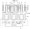
- FIG. 4 is an explanatory view schematically showing a configuration of a second electric resistor 85, which is the configuration of the ink jet head 1.
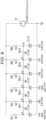
- FIG. 5 is an explanatory diagram showing a configuration of a drive circuit 70 of the ink jet head 1 with a part thereof omitted
- FIG. 6 is an explanatory diagram showing the configuration of the drive circuit 70 in an example of driving the ink jet head 1.
- FIG. 7 is an explanatory diagram showing an example of voltages in the example of driving the inkjet head 1.
- FIG. 8 is an explanatory view schematically showing a configuration of the inkjet recording apparatus 100 using the ink jet head 1. In each of the drawings, the configuration is shown enlarged, reduced, or omitted as appropriate for a purpose of description.
- the ink jet head 1 includes a base 10, a pair of actuators 20 each including a plurality of piezoelectric poles 21 and 22, a vibration plate 30, a flow path member 40, a nozzle plate 50 having a plurality of nozzles 51, a frame portion 60 as a structural portion, and the drive circuit 70.
- the ink jet head 1 forms a plurality of pressure chambers 31 by the vibration plate 30, the flow path member 40, and the nozzle plate 50, and ejects ink as a liquid within the pressure chambers 31 from the nozzles 51 by vibrating the vibration plate 30 using the piezoelectric poles 21 of the actuators 20.
- the ink jet head 1 includes one or two actuators 20.
- the two actuators 20 are arranged side by side in a direction orthogonal to an arrangement direction of the plurality of piezoelectric poles 21 and 22 as piezoelectric bodies.
- the base 10 is a support member that supports the actuators 20.
- the base 10 is formed in a block shape or a plate shape, for example.
- the actuators 20 are fixed to the base 10.
- the actuator 20 includes the plurality of piezoelectric poles 21 and 22 that are piezoelectric members (piezoelectric elements).
- the actuator 20 forms a piezoelectric pole row by the plurality of piezoelectric poles 21 and 22.
- the actuator 20 includes a plurality of drive piezoelectric poles (piezoelectric bodies) 21, a plurality of support piezoelectric poles (piezoelectric bodies) 22 alternately arranged with the plurality of drive piezoelectric poles 21 along a row direction of the piezoelectric pole row, and a coupling portion 26 integrally coupling the plurality of piezoelectric poles 21 and 22 on a base 10 side.
- the actuator 20 is formed of a laminated piezoelectric member.
- the laminated piezoelectric member is formed by laminating a plurality of piezoelectric layers 211 and a plurality of internal electrodes 221 and 222.
- the actuator 20 includes external electrodes 223 and 224 formed on the plurality of drive piezoelectric poles 21.
- the laminated piezoelectric member constituting the actuator 20 is formed by laminating and sintering sheet-shaped piezoelectric materials on which electrode layers as the internal electrodes 221 and 222 are formed.
- the actuator 20 forms grooves 23 by dicing the laminated piezoelectric member joined to the base 10 in advance from an end surface opposite to the base 10 side, thereby forming, at predetermined intervals, the plurality of piezoelectric poles 21 and 22 each having a rectangular columnar shape.
- the external electrodes 223 and 224 are provided on the plurality of formed columnar piezoelectric members (piezoelectric elements).
- the plurality of drive piezoelectric poles 21 and the plurality of support piezoelectric poles 22 are arranged in a longitudinal direction of the actuator 20 at predetermined intervals.
- a vibration direction of the drive piezoelectric poles 21 and the support piezoelectric poles 22 is a lamination direction of the plurality of piezoelectric layers 211.
- the drive piezoelectric pole 21 is an actuator that is driven by applying a voltage and vibrates the vibration plate 30.
- the support piezoelectric pole 22 is a non-driven piezoelectric pole that supports the vibration plate 30 and is restricted from vibrating the vibration plate 30 by the flow path member 40 even when a voltage is applied thereto.
- each of the plurality of drive piezoelectric poles 21 and the plurality of support piezoelectric poles 22 is formed in a rectangular columnar shape having the same outer shape.
- the laminated piezoelectric member is divided into a plurality of parts by a plurality of grooves 23 having a predetermined depth formed in the actuator 20 (laminated piezoelectric member) except for the coupling portion 26, thereby forming the plurality of drive piezoelectric poles 21 and the plurality of support piezoelectric poles 22.
- the plurality of grooves 23 formed in the actuator 20 have the same width and the same interval.
- the plurality of drive piezoelectric poles 21 and the plurality of support piezoelectric poles 22, which are alternately arranged, are arranged in one direction at the same pitch.
- each of the plurality of drive piezoelectric poles 21 and the plurality of support piezoelectric poles 22 is formed in a rectangular columnar shape.
- the plurality of drive piezoelectric poles 21 are arranged at positions respectively facing the plurality of pressure chambers 31 formed by the vibration plate 30, the flow path member 40, and the nozzle plate 50, with the vibration plate 30 interposed therebetween, in the lamination direction of the plurality of piezoelectric layers 211.
- a center position in the drive piezoelectric poles 21 in the row direction of the piezoelectric pole row and a center position in the pressure chambers 31 in the row direction of the piezoelectric pole row are arranged in the lamination direction of the plurality of piezoelectric layers 211 with the vibration plate 30 interposed therebetween.
- the plurality of support piezoelectric poles 22 are arranged at positions respectively facing a plurality of partition wall portions 43 (described later) of the flow path member 40, with the vibration plate 30 interposed therebetween, in the lamination direction of the plurality of piezoelectric layers 211.
- a center position in the support piezoelectric poles 22 in the row direction of the piezoelectric pole row and a center position in the partition wall portions 43 in the same direction as the row direction of the piezoelectric pole row are arranged in the lamination direction of the plurality of piezoelectric layers 211.
- the plurality of drive piezoelectric poles 21 and the plurality of support piezoelectric poles 22 include the plurality of piezoelectric layers 211 laminated in a Z direction, and the internal electrodes 221 and 222 formed on main surfaces of the piezoelectric layers 211.
- the drive piezoelectric pole 21 and the support piezoelectric pole 22 have the same laminated structure.
- the drive piezoelectric pole 21 each includes the external electrodes 223 and 224 as surface wirings formed on the surfaces.
- the piezoelectric layer 211 is formed in a thin plate shape from a piezoelectric ceramic material such as a PZT (lead zirconate titanate) based material or a lead-free KNN (sodium potassium niobate) based material.
- a thickness direction of the piezoelectric layer 211 is along the lamination direction in which the plurality of piezoelectric layers 211 are laminated.
- the plurality of laminated piezoelectric layers 211 are bonded to each other.
- the thickness direction and the lamination direction of the piezoelectric layers 211 are along a vibration direction of the piezoelectric poles 21 when driven.
- the laminated piezoelectric member forming the drive piezoelectric poles 21 and the support piezoelectric poles 22 may further include a dummy layer 212 on either or both of end portions on the base 10 side and a nozzle plate 50 side.
- the dummy layer 212 is formed of, for example, the same material as the piezoelectric layer 211, has an electrode only on one side, and is not deformed because no electric field is applied thereto.
- the dummy layer 212 does not function as a piezoelectric body, but serves as a base for fixing the actuator 20 to the base 10, or serves as a polishing allowance for polishing to improve accuracy during and after assembly.
- the internal electrodes 221 and 222 are conductive films formed of a sinterable conductive material such as silver palladium, and each having a predetermined shape.
- the internal electrodes 221 and 222 are formed in predetermined regions on the main surfaces of the piezoelectric layers 211.
- the internal electrodes 221 and 222 have different poles.
- one internal electrode 221 is formed in a region that reaches one end of the piezoelectric layer 211 but does not reach the other end of the piezoelectric layer 211 in a width direction orthogonal to both the row direction and the vibration direction, which are the arrangement direction of the plurality of drive piezoelectric poles 21 and the plurality of support piezoelectric poles 22.
- the internal electrode 221 may be referred to as a first internal electrode 221.
- the other internal electrode 222 is formed in a region that does not reach one end of the piezoelectric layer 211 but reaches the other end of the piezoelectric layer 211 in the width direction orthogonal to both the row direction and the vibration direction.
- the internal electrode 222 may be referred to as a second internal electrode 222.
- the external electrodes 223 and 224 are formed on the surfaces of each of the plurality of drive piezoelectric poles 21, and are formed by collecting end portions of the internal electrodes 221 and 222.
- the external electrode 223 is formed on one end surface of the piezoelectric layer 211 in the width direction.
- the external electrode 223 may be referred to as a first external electrode 223.
- the external electrode 224 is formed on the other end surface of the piezoelectric layer 211 in the width direction.
- the external electrode 224 may extend to an end surface of the piezoelectric layer 211 on the base 10 side.
- the external electrode 224 may be referred to as a second external electrode 224.
- the external electrodes 223 and 224 are formed of Ni, Cr, Au, or the like by a known method such as plating or sputtering.
- the external electrode 223 and the external electrode 224 have different poles.
- the first external electrode 223 and the second external electrode 224 are respectively formed on different side surfaces of each of the plurality of drive piezoelectric poles 21.
- the first external electrode 223 is an individual electrode, and the second external electrode 224 is a common electrode. As shown in FIG. 4 , the first external electrode 223 is formed on each of the plurality of drive piezoelectric poles 21. One second external electrode 224 is provided and connects all of the plurality of drive piezoelectric poles 21. The plurality of first external electrodes 223 and the single second external electrode 224 are disposed independently of each other.
- the first external electrode 223 is connected to a plurality of first internal electrodes 221 formed in one drive piezoelectric pole 21.
- the single second external electrode 224 is a ground electrode.
- the single second external electrode 224 is connected to the plurality of second internal electrodes 222 formed in the plurality of provided drive piezoelectric poles 21.
- the plurality of first external electrodes 223 and the single second external electrode 224 are connected to an FPC 71 serving as a flexible substrate (described later) of the drive circuit 70.
- the single second external electrode 224 is provided on facing outer surfaces of the pair of actuators 20.
- the individual external electrodes 223 and 224 are connected to a control unit 116 serving as a drive unit via the drive circuit 70, and a signal capable of driving and controlling each piezoelectric pole 21 is input under the control of a control circuit 1161.
- the piezoelectric pole 21 When the drive signal is input to the internal electrodes 221 and 222 via the external electrodes 223 and 224 and an electric field is applied, the piezoelectric pole 21 is displaced in a d33 direction, and the vibration direction of the piezoelectric pole 21 is along the lamination direction of the piezoelectric layers 211.
- the drive piezoelectric pole 21 vibrates longitudinally along the lamination direction of the piezoelectric layers 211.
- Longitudinal vibration referred to here is, for example, "vibration in the thickness direction defined by the piezoelectric constant d33".
- the drive piezoelectric pole 21 displaces the vibration plate 30 in the lamination direction of the piezoelectric layers 211 by the longitudinal vibration to deform the pressure chamber 31.
- each piezoelectric pole 21 includes 3 or more and 50 or less piezoelectric layers 211, a thickness of each piezoelectric layer 211 is 10 ⁇ m or more and 40 ⁇ m or less, and a product of the thickness and the total number of laminated layers is less than 1000 ⁇ m.
- the vibration plate 30 is fixed to end portions of the plurality of drive piezoelectric poles 21 and the plurality of support piezoelectric poles 22 of the pair of actuators 20 on a side opposite to the coupling portion 26 in the Z direction.
- the vibration plate 30 is joined to surfaces of the plurality of piezoelectric poles 21 and 22 opposite to the base 10 in the vibration direction of the plurality of piezoelectric poles 21, that is, surfaces of the plurality of piezoelectric poles 21 and 22 on the nozzle plate 50 side.
- the vibration plate 30 is formed in a flat plate shape.
- the vibration plate 30 is, for example, a metal plate.
- the vibration plate 30 is deformable by deformation of the drive piezoelectric poles 21.
- the vibration plate 30 forms the pressure chambers 31 together with the flow path member 40 and the nozzle plate 50.
- the vibration plate 30 extends in the arrangement direction (row direction) of the plurality of piezoelectric poles 21 and 22. That is, the vibration plate 30 extends along a plane orthogonal to the vibration direction of the piezoelectric poles 21.
- One main surface of the vibration plate 30 is joined to the drive piezoelectric poles 21 and the support piezoelectric poles 22 of the actuator 20, and the frame portion 60.
- the other main surface of the vibration plate 30 is joined to the flow path member 40.
- the vibration plate 30 is formed of a nickel or SUS plate, and a thickness dimension thereof along the vibration direction is approximately 5 ⁇ m to 15 ⁇ m.
- the vibration plate 30 may have a fold or step formed at a portion adjacent to a vibration portion that vibrates due to driving of the drive piezoelectric poles 21 or between vibration portions adjacent to each other so as to be easily displaced by the driving of the drive piezoelectric poles 21.
- the vibration plate 30 has, in a region joined to the frame portion 60, a through hole 33 communicating with a common chamber 61 (described later) formed in the frame portion 60.
- the through hole 33 may be provided with a filter having a large number of pores through which a liquid can pass.
- One or more through holes 33 may be formed.
- the flow path member 40 is provided between the vibration plate 30 and the nozzle plate 50.
- the flow path member 40 includes a peripheral wall portion 41 and the plurality of partition wall portions 43.
- a division wall portion is provided to divide the pressure chambers 31 driven by the actuators 20.
- the peripheral wall portion 41 and the partition wall portions 43 are provided between the vibration plate 30 and the nozzle plate 50 to form, together with the vibration plate 30 and the nozzle plate 50, a predetermined ink flow path including the plurality of pressure chambers 31 separated from each other and a plurality of individual flow paths 32 separated from each other and allowing the pressure chambers 31 to communicate with the common chamber 61.
- the peripheral wall portion 41 surrounds a region forming the plurality of pressure chambers 31 and the plurality of individual flow paths 32 between the vibration plate 30 and the nozzle plate 50.
- the plurality of partition wall portions 43 partition a region in the peripheral wall portion 41 into the plurality of pressure chambers 31 and the plurality of individual flow paths 32. That is, both side walls of the plurality of pressure chambers 31 (the plurality of individual flow paths 32) in a parallel direction are formed by the partition wall portions 43.
- the plurality of partition wall portions 43 are provided at positions facing the support piezoelectric poles 22 with the vibration plate 30 interposed therebetween in the Z direction. Accordingly, the partition wall portions 43 restrict displacement of the support piezoelectric poles 22 at portions of the support piezoelectric poles 22 and the vibration plate 30 where the support piezoelectric poles 22 are fixed.
- the plurality of pressure chambers 31 are spaces formed on one side of a vibration region of the vibration plate 30, and communicate with the common chamber 61 via the individual flow paths 32 and the through hole 33.
- the plurality of pressure chambers 31 communicate with the nozzles 51 formed in the nozzle plate 50.
- the pressure chambers 31 are closed by the vibration plate 30 on a side opposite to the nozzle plate 50.
- the plurality of nozzles 51 are formed in the nozzle plate 50 at positions facing the plurality of pressure chambers 31.
- the nozzle plate 50 is formed of a metal such as SUS or Ni, or a resin material such as polyimide, and has a rectangular plate shape with a thickness of approximately 10 ⁇ m to 100 ⁇ m.
- the nozzle plate 50 is joined to surfaces of the peripheral wall portion 41 and the partition wall portions 43 opposite to the vibration plate 30 so as to cover openings of the pressure chambers 31 on one side.
- the plurality of nozzles 51 are arranged in the same direction as the parallel direction of the plurality of pressure chambers 31 to form a nozzle row.
- a nozzle row For example, in a configuration in which one actuator 20 is provided, one row of the nozzles 51 is provided, and in a configuration in which the pair of actuators 20 are provided, two rows of the nozzles 51 are provided.
- the frame portion 60 is a structure joined to the vibration plate 30 together with the piezoelectric poles 21 and 22.
- a pair of frame portions 60 are provided on main surfaces of the piezoelectric poles 21 and 22 and the vibration plate 30 on a side opposite to the peripheral wall portion 41.
- the pair of frame portions 60 are adjacent to the actuator 20.
- the frame portions 60 constitute an outer shell of the ink jet head 1.
- the common chamber 61 serving as a flow path of a liquid is formed inside the frame portion 60.
- the common chamber 61 is formed inside the frame portion 60.
- the common chamber 61 communicates with the through hole 33 formed in the vibration plate 30, and communicates with the pressure chambers 31 through the individual flow paths 32.
- the pair of frame portions 60 in each of which the common chamber 61 is formed are provided, a pair of individual flow paths 32 are provided, and the pair of individual flow paths 32 are connected to the pair of common chambers 61, respectively.
- one common chamber 61 and one individual flow path 32 are used to supply ink to the pressure chamber 31, and the other common chamber 61 and the other individual flow path 32 are used to discharge ink from the pressure chamber 31.
- the pair of common chambers 61 and the pair of individual flow paths 32 may be used for supplying ink, or may be commonly used for supplying and discharging ink.
- the drive circuit 70 includes the flexible printed circuit (FPC) 71 having one end connected to the external electrodes 223 and 224, a drive IC 72 mounted on the FPC 71, and a printed wiring board 73 mounted on the other end of the FPC 71.
- FPC flexible printed circuit
- the drive circuit 70 drives the drive piezoelectric pole 21 by applying a drive voltage to the external electrodes 223 and 224 by the drive IC 72, increases or decreases a volume of the pressure chamber 31, and causes droplets to be ejected from the nozzle 51.
- the FPC 71 is connected to one side surface of the laminated piezoelectric member and is connected to the plurality of external electrodes 223 and 224.
- a chip on film (COF) on which the drive IC 72 is mounted as an electronic component is used as the FPC 71.
- the drive IC 72 is connected to the external electrodes 223 and 224 via the FPC 71.
- the drive IC 72 is an electronic component used for ejection control.
- the drive IC 72 generates a control signal and a drive signal for operating each drive piezoelectric pole 21.
- the drive IC 72 generates the control signal for controlling a timing of ejecting the ink and selection of the drive piezoelectric pole 21 to eject the ink according to an image signal received from the control unit 116 of the ink jet recording apparatus 100 on which the ink jet head 1 is mounted.
- the drive IC 72 generates a voltage to be applied to the drive piezoelectric pole 21, that is, the drive signal, according to the control signal from the control unit 116.
- the drive IC 72 applies the drive signal to the drive piezoelectric pole 21, the drive piezoelectric pole 21 is driven so as to displace the vibration plate 30 and change a volume of the pressure chamber 31.
- the ink filled in the pressure chamber 31 generates pressure vibration. Due to the pressure vibration, the ink is ejected from the nozzle 51 communicating with the pressure chamber 31.
- the ink jet head 1 may implement gradation expression by changing an amount of ink droplets that land on one pixel.
- the inkjet head 1 may change the amount of ink droplets that land on one pixel by changing the number of times of ink ejection.
- the drive IC 72 is an example of an application unit that applies the drive signal to the drive piezoelectric pole 21.
- the drive IC 72 includes a data buffer, a decoder, and a driver.
- the data buffer stores printing data in time series for each drive piezoelectric pole 21.
- the decoder controls the driver based on the printing data stored in the data buffer for each drive piezoelectric pole 21.
- the driver outputs a drive signal for operating each drive piezoelectric pole 21 based on the control of the decoder.
- the drive signal is, for example, a voltage applied to each drive piezoelectric pole 21.
- the printed wiring board 73 is a printing wiring assembly (PWA) on which various electronic components and connectors are mounted, and includes a head control circuit 731.
- the printed wiring board 73 is connected to the control unit 116 of the ink jet recording apparatus 100.
- the drive circuit 70 selects and supplies a drive signal or a standby voltage to the plurality of drive piezoelectric poles 21 based on a command from the control unit 116 of the ink jet recording apparatus 100 and the printing data.
- the drive circuit 70 drives the drive piezoelectric pole 21 using single nozzle driving and multi-nozzle simultaneous driving as a drive pattern.
- the single nozzle driving is a drive pattern in which the adjacent drive piezoelectric poles 21 are not driven, a drive signal is applied to the first external electrode 223 in one channel, and one drive piezoelectric pole 21 is driven.
- the multi-nozzle simultaneous driving is a drive pattern in which a drive signal is applied to the first external electrodes 223 in a plurality of channels, and all of the plurality of drive piezoelectric poles 21 or a part of the adjacent drive piezoelectric poles 21 are driven simultaneously.
- the drive circuit 70 includes a drive signal source 81 that outputs a drive signal to be applied to the first external electrode 223 which is an individual electrode, a standby voltage source 82 that outputs a standby voltage to be applied to the second external electrode 224 which is a common electrode, switching elements 83 that selectively connect the drive piezoelectric poles 21 to one of the drive signal source 81 and the standby voltage source 82, a plurality of first electric resistors 84 that are internal resistances of the switching elements 83 between the drive piezoelectric poles 21 and the drive signal source 81 or the standby voltage source 82, and a single or a plurality of second electric resistors 85 that connect adjacent drive piezoelectric poles 21 that are at least a part of the plurality of drive piezoelectric poles 21 among the plurality of drive piezoelectric poles 21.
- the switching element 83 is switched based on the printing data.
- the switching element 83 connects the drive piezoelectric pole 21, which is driven to eject ink, to the drive signal source 81, and connects the non-driven drive piezoelectric pole 21, which does not cause ink to be ejected, to the standby voltage source 82.
- the plurality of switching elements 83 are included in, for example, the drive IC 72.
- the first electric resistor 84 is an internal resistance of the switching element 83.
- a resistance value of the first electric resistor 84 is RA.
- a resistor may be added to the first electric resistor 84 in series with the switching element 83 outside the switching element 83.
- the resistance value RA of the first electric resistor 84 is a sum of the internal resistance of the switching element 83 and a resistance added outside the switching element 83.
- the second electric resistor 85 electrically connects the first external electrodes 223, which are individual electrodes of a part of adjacent drive piezoelectric poles 21, with a predetermined resistance value. That is, the second electric resistor 85 includes a plurality of electric resistances 851 provided between the first external electrodes 223 of the adjacent drive piezoelectric poles 21.
- the number of electric resistances 851 is n-1, where n is the number of first external electrodes 223 to be connected.
- a resistance value of the electric resistance 851 is RB. As the resistance value RB of the electric resistance 851 decreases, an ejection speed or an ejection volume during the single nozzle driving decreases.
- the resistance value RB of the electric resistance 851 is set to match the ejection speed and the ejection volume for the multi-nozzle simultaneous driving.
- the second electric resistor 85 is formed of, for example, a thin film formed over the first external electrodes 223 of the plurality of drive piezoelectric poles 21 that are formed in the actuator 20 and subjected to multi-nozzle simultaneous driving.
- the second electric resistor 85 electrically connects the first external electrodes 223 of all the drive piezoelectric poles 21.
- a plurality of second electric resistors 85 may be provided, and the second electric resistors 85 may connect the first external electrodes 223 of a part of the drive piezoelectric poles 21 that are subjected to multi-nozzle simultaneous driving.
- the second electric resistor 85 is formed of, for example, a metal with high resistivity such as a nickel-chromium alloy or titanium, or a carbon film (carbon).
- a thickness of the second electric resistor 85 is several nanometers to several micrometers, and is formed by forming a film by vacuum deposition, sputtering, or the like, or printing by a printing method such as screen printing.
- the second electric resistor 85 extends in an arrangement direction of the first external electrodes 223, and is formed of a thin film having a uniform width in a direction (width direction) orthogonal to a longitudinal direction and a thickness direction.
- the plurality of electric resistances 851 formed in the second electric resistor 85 are formed by, for example, trimming portions 852 formed by a plurality of slits 853 formed between the plurality of first external electrodes 223 by laser processing or the like.
- the plurality of electric resistances 851 are formed by partially narrowing a width and increasing a length, due to the plurality of slits 853 formed between adjacent first external electrodes 223 to be connected.
- the resistance value RB of the electric resistance 851 can be set by adjusting a shape of the trimming portion 852, specifically, the number, length, and width of the slits 853.
- the trimming portions 852 are formed by alternately forming three rectangular slits 853 arranged in the longitudinal direction of the second electric resistor 85 so as to be shifted in the width direction orthogonal to the longitudinal direction and the thickness direction of the second electric resistor 85.
- the number, width, length, and shape of the slits 853 are appropriately set according to the resistance value RB of the electric resistance 851.
- the slit 853 may not be rectangular, but may have a shape that is elongated in the width direction of the second electric resistor 85 and is curved in end portions, a semicircular shape, a polygonal shape other than a rectangular shape, or the like.
- the second electric resistor 85 is an integral thin film on the actuator 20 so as to connect the plurality of first external electrodes 223, and the plurality of trimming portions 852 are provided to form the plurality of electric resistances 851.
- the second electric resistor 85 is not limited to this configuration, and for example, the second electric resistor 85 may be configured such that the electric resistances 851 are provided between the switching elements 83 and the first external electrodes 223 that perform the multi-nozzle simultaneous driving, and between a plurality of adjacent first external electrodes 223.
- the second electric resistor 85 may be provided in the FPC 71 or the drive IC 72.
- the second electric resistor 85 may be formed of a semiconductor such as a transistor.
- it is desirable that the resistance value RB of the electric resistance 851 can be adjusted for the second electric resistor 85 by trimming or the like.
- the drive piezoelectric pole 21 when the switching element 83 is switched and a voltage is applied to the drive piezoelectric pole 21 according to a drive signal, the drive piezoelectric pole 21 extends.
- the extended drive piezoelectric pole 21 deforms the vibration plate 30, and a volume of the pressure chamber 31 decreases. That is, the vibration plate 30 applies a pressure to ink in the pressure chamber 31, and ink droplets are ejected from the nozzle 51.
- the support piezoelectric pole 22 When a certain drive piezoelectric pole 21 extends, the support piezoelectric pole 22 also extends due to a mechanical reaction force.
- a deformation amount of the vibration plate 30 with respect to a deformation amount of the drive piezoelectric pole 21 is smaller in the multi-nozzle simultaneous driving than in the single nozzle driving. Since the deformation amount of the vibration plate 30 in the multi-nozzle simultaneous driving is smaller than that in the single nozzle driving, a pressure generated in the pressure chamber 31 is smaller in the multi-nozzle simultaneous driving than in the single nozzle driving according to the related-art technique. Therefore, a speed or volume of ink droplets to be ejected may vary depending on a printing pattern, resulting in a so-called crosstalk problem that deteriorates printing quality.
- the ink jet head 1 electrically connects the adjacent first external electrodes 223 that perform the multi-nozzle simultaneous driving by the second electric resistor 85, and includes the electric resistances 851 between the first external electrodes 223. Accordingly, in the case of the single nozzle driving, a part of a current of a drive signal applied to the first external electrode 223 provided on the drive piezoelectric pole 21 that is driven flows through the electric resistance 851 to the first external electrode 223 of the adjacent drive piezoelectric pole 21. Therefore, a voltage amplitude for driving the drive piezoelectric pole 21 is reduced. In the case of the multi-nozzle simultaneous driving, since voltages of the plurality of first external electrodes 223 that are driven simultaneously are the same, no current flows through the electric resistance 851, and a voltage amplitude is not reduced.
- the inkjet head 1 can eliminate dot misalignment or density unevenness due to the drive pattern.
- the single nozzle driving and the multi-nozzle simultaneous driving are performed in six channels ChA to ChF.
- the drive piezoelectric poles 21 in the channels ChA to ChF are denoted by CA to CF, respectively, and the first electric resistors 84 provided between the drive piezoelectric poles CAto CF and the switching elements 83 in the channels ChA to ChF are denoted by 841 to 846, respectively.
- the electric resistances 851 of the second electric resistor 85 provided between the first external electrodes 223 of the drive piezoelectric poles CA to CF are denoted by 8511 to 8515.
- FIG. 7 shows an example of a simulation of voltages applied to the drive piezoelectric poles CA to CF (first external electrodes 223) in the example shown in FIG. 6 .
- voltage values applied to the drive piezoelectric poles CA to CF are denoted by VAto VF, respectively.
- a vertical axis represents voltage and a horizontal axis represents time.
- a voltage amplitude of the voltage value VB of the drive piezoelectric pole CB that is subjected to single nozzle driving is smaller than voltage amplitudes of the voltage values VD to VF of the drive piezoelectric poles CD to CF that are subjected to multi-nozzle simultaneous driving. Therefore, a phenomenon of crosstalk in which a pressure generated in the pressure chamber 31 is smaller in the multi-nozzle simultaneous driving than in the single nozzle driving is corrected, and the pressure generated in the pressure chamber 31 becomes substantially the same value in the single nozzle driving and the multi-nozzle simultaneous driving, and a crosstalk problem that deteriorates printing quality due to variations in speed or volume of ink droplets ejected depending on a printing pattern is solved.
- the voltage values VA and VC of the non-driven drive piezoelectric poles CA and CC adjacent to the drive piezoelectric pole CB subjected to the single nozzle driving are standby voltages.
- a slight voltage amplitude occurs between the voltage value VA and the voltage value VC, and a minute pressure is generated in the pressure chamber 31, but a problem of ink being ejected from a non-driven nozzle does not occur since a pressure sufficient to cause ink to be ejected is not generated.
- the inkjet recording apparatus 100 includes a housing 111, a medium supply unit 112, an image forming unit 113, a medium discharge unit 114, a conveyance device 115, and the control unit 116.
- the inkjet recording apparatus 100 is a liquid ejection apparatus that performs image forming processing on a sheet P by ejecting a liquid such as ink while conveying the sheet P as a print medium that is an ej ection target along a predetermined conveyance path R from the medium supply unit 112 to the medium discharge unit 114 through the image forming unit 113.
- the housing 111 constitutes an outer shell of the ink jet recording apparatus 100.
- a discharge port through which the sheet P is to be discharged to the outside is provided at a predetermined position of the housing 111.
- the medium supply unit 112 includes a plurality of sheet feed cassettes, and can stack and hold a plurality of sheets P of various sizes.
- the medium discharge unit 114 includes a sheet discharge tray that can hold the sheet P discharged from the discharge port.
- the image forming unit 113 includes a support portion 117 that supports the sheet P, and a plurality of head units 130 that face the support portion 117 above the support portion 117.
- the support portion 117 includes a conveyance belt 118 provided in a loop shape in a predetermined region where image formation is performed, a support plate 119 that supports the conveyance belt 118 from a back side, and a plurality of belt rollers 120 provided on the back side of the conveyance belt 118.
- the support portion 117 supports the sheet P on a holding surface that is an upper surface of the conveyance belt 118, and conveys the sheet P downstream by sending the conveyance belt 118 at a predetermined timing by rotation of the belt rollers 120.
- the head unit 130 includes a plurality of (for example, four colors) inkjet heads 1, ink tanks 132 as liquid tanks respectively mounted on the inkjet heads 1, connection flow paths 133 that connect the inkjet heads 1 and the ink tanks 132, and supply pumps 134.
- the inkjet heads 1 of four colors: cyan, magenta, yellow, and black, and the ink tanks 132 that respectively store ink of these colors are provided.
- the ink tank 132 is connected to the ink jet head 1 by the connection flow path 133.
- a negative pressure control device such as a pump (not shown) is connected to the ink tank 132.
- a negative pressure in the ink tank 132 is controlled by the negative pressure control device according to water head values of the ink jet head 1 and the ink tank 132, thereby forming the ink supplied to each nozzle 51 of the inkjet head 1 into a meniscus having a predetermined shape.
- the supply pump 134 is, for example, a liquid sending pump formed of a piezoelectric pump.
- the supply pump 134 is provided in the supply flow path.
- the supply pump 134 is connected to the control circuit 1161 of the control unit 116 through a wiring and can be controlled by the control unit 116.
- the supply pump 134 supplies a liquid to the ink jet head 1.
- the conveyance device 115 conveys the sheet P along the conveyance path R from the medium supply unit 112 to the medium discharge unit 114 through the image forming unit 113.
- the conveyance device 115 includes a plurality of guide plate pairs 121 disposed along the conveyance path R and a plurality of conveyance rollers 122.
- Each of the plurality of guide plate pairs 121 includes a pair of plate members facing each other across the sheet P to be conveyed, and guides the sheet P along the conveyance path R.
- the conveyance roller 122 is driven and rotated under the control of the control unit 116, thereby conveying the sheet P downstream along the conveyance path R.
- Sensors that detect a state of sheet conveyance are disposed at various locations in the conveyance path R.
- the control unit 116 includes a control circuit 1161 such as a central processing unit (CPU) serving as a controller, a read only memory (ROM) that stores various programs, a random access memory (RAM) that temporarily stores various variable data, image data, and the like, and an interface unit that receives data from the outside and outputs data to the outside.
- a control circuit 1161 such as a central processing unit (CPU) serving as a controller, a read only memory (ROM) that stores various programs, a random access memory (RAM) that temporarily stores various variable data, image data, and the like, and an interface unit that receives data from the outside and outputs data to the outside.
- CPU central processing unit
- ROM read only memory
- RAM random access memory
- the control unit 116 when the control unit 116 detects a print instruction by a user operating an operation input unit at an interface, the control unit 116 drives the ink jet head 1 by driving the conveyance device 115 to convey the sheet P and outputting a printing signal to the head unit 130 at a predetermined timing.
- the inkjet head 1 transmits a drive signal to the drive IC 72 according to an image signal corresponding to image data, and applies a drive voltage to the internal electrodes 221 and 222 to selectively drive the drive piezoelectric pole 21 for an ejection target, for example, to vibrate the drive piezoelectric pole 21 vertically in a lamination direction, thereby changing a volume of the pressure chamber 31 to eject ink from the nozzle 51 and form an image on the sheet P held on the conveyance belt 118.
- the control unit 116 drives the supply pump 134 to supply the ink from the ink tank 132 to the common chamber 61 of the inkjet head 1.
- the drive circuit 70 switches the switching element 83 to apply a standby voltage to the support piezoelectric pole 22 that does not cause ink to be ejected, but the embodiment is not limited thereto.
- the switching element 83 may disconnect the support piezoelectric pole 22, which does not cause ink to be ejected, from the drive signal source 81.
- FIG. 10 shows an example of a simulation of voltages applied to the drive piezoelectric poles CA to CF (first external electrodes 223) in the example shown in FIG. 9 . As shown in FIG.
- a so-called edge may occur in which a voltage difference occurs between the drive piezoelectric pole 21 (first external electrode 223) located at an end portion and the adjacent drive piezoelectric pole 21.
- the drive piezoelectric pole 21 located at the end portion may be used as a dummy that is not to be driven, or the same voltage as the second drive piezoelectric pole 21 from the end portion may be applied without providing the corresponding nozzle 51.
- the second electric resistor 85 extends in an arrangement direction of the first external electrodes 223, and is formed of a thin film having a uniform width in a direction (width direction) orthogonal to a longitudinal direction and a thickness direction, but the embodiment is not limited thereto.
- a width of the second electric resistor 85 may be partially changed in order to increase a resistance difference between a region connected to the first external electrode 223 and the trimming portion 852 constituting the electric resistance 851.
- the second electric resistor 85 may be configured such that a width of the region connected to the first external electrode 223 in the direction orthogonal to the longitudinal direction and the thickness direction is larger than a width of a region forming the electric resistance 851.
- the liquid ejection apparatus 100 ejects ink as a liquid from the liquid ejection head 1, but the liquid is not limited to ink. That is, the liquid ejection head 1 and the liquid ejection apparatus 100 can be used for 3D printers, industrial manufacturing machines, and medical applications, for example, and can eject various liquids.
- a liquid ejection head and a liquid ejection apparatus capable of eliminating dot misalignment or density unevenness due to a drive pattern by providing electric resistances between a plurality of individual electrodes that individually apply voltages to a plurality of drive piezoelectric poles.
Landscapes
- Particle Formation And Scattering Control In Inkjet Printers (AREA)
Abstract
Provided are a liquid ejection head and a liquid ejection apparatus capable of eliminating dot misalignment or density unevenness due to a drive pattern. A liquid ejection head according to an embodiment includes a plurality of pressure chambers, an actuator, a plurality of individual electrodes, a nozzle plate, a plurality of switching elements, and a plurality of electric resistances. The actuator includes a plurality of piezoelectric bodies that change volumes of the pressure chambers according to a drive signal. The plurality of individual electrodes are respectively provided on the plurality of piezoelectric bodies. The nozzle plate has a plurality of nozzles communicating with the plurality of pressure chambers, respectively. The switching element selectively connects the drive signal for the piezoelectric body. The switching elements are electrically connected to the plurality of individual electrodes. The electric resistances electrically connect the individual electrodes of the piezoelectric bodies adjacent to each other.
Description
- Embodiments described herein relate generally to a liquid ejection head and a liquid ejection apparatus.
- A push mode type piezoelectric inkjet head that ejects ink as a liquid is known in related art. The ink jet head includes a plurality of nozzles, a plurality of pressure chambers, a vibration plate, and an actuator in which a plurality of piezoelectric drive piezoelectric poles and a plurality of support piezoelectric poles are alternately formed and the poles are electrically connected to a drive circuit. The actuator extends and contracts the drive piezoelectric poles to displace the vibration plate, thereby changing volumes of the pressure chambers to eject ink from the nozzles.
- However, when adjacent nozzles are driven simultaneously, the support piezoelectric poles are deformed by a reaction force of a driving force of the actuator, a generated pressure is lower than when a single nozzle is driven, and an ejection speed or volume of the ink decreases. When the ejection speed or volume of the ink decreases, dot misalignment or density unevenness occurs due to a drive pattern.
- To this end, there is provided a liquid ejection head according to
claim 1. Preferred embodiments are set out in the dependent claims. There is also provided a liquid ejection apparatus according to claim 15. -
-
FIG. 1 is a cross-sectional view showing a configuration of a liquid ejection head according to an embodiment, with a part thereof omitted; -
FIG. 2 is a cross-sectional view showing the configuration with a part thereof omitted; -
FIG. 3 is a cross-sectional view showing the configuration with a part thereof omitted; -
FIG. 4 is an explanatory view schematically showing a configuration of an electric resistor; -
FIG. 5 is an explanatory diagram showing a configuration of a drive circuit with a part thereof omitted; -
FIG. 6 is an explanatory diagram showing the configuration in an example of driving the liquid ejection head; -
FIG. 7 is an explanatory diagram showing an example of voltages in the example; -
FIG. 8 is an explanatory view schematically showing a configuration of a liquid ejection apparatus; -
FIG. 9 is an explanatory diagram showing a configuration of a drive circuit in an example of driving a liquid ejection head according to another embodiment; and -
FIG. 10 is an explanatory diagram showing an example of voltages in the example. - In general, according to an embodiment, a liquid ejection head and a liquid ejection apparatus capable of eliminating dot misalignment or density unevenness due to a drive pattern is provided.
- A liquid ejection head according to an embodiment includes a plurality of pressure chambers, an actuator, a plurality of individual electrodes, a nozzle plate, a plurality of switching elements, and a plurality of electric resistances. The actuator includes a plurality of piezoelectric bodies that change volumes of the pressure chambers according to a drive signal. The plurality of individual electrodes are respectively provided on the plurality of piezoelectric bodies. The nozzle plate has a plurality of nozzles communicating with the plurality of pressure chambers, respectively. The switching element selectively connects the drive signal for the piezoelectric body. The switching elements are electrically connected to the plurality of individual electrodes. The electric resistances electrically connect the individual electrodes of the piezoelectric bodies adjacent to each other.
- Hereinafter, an
inkjet head 1 as a liquid ejection head and aninkjet recording apparatus 100 as a liquid ejection apparatus according to an embodiment will be described with reference toFIGS. 1 to 8 .FIGS. 1 to 3 are cross-sectional views schematically showing a configuration of theinkjet head 1.FIG. 1 is a cross-sectional view showing the configuration of theinkjet head 1 with a part thereof omitted,FIG. 2 is a cross-sectional view showing the configuration of theink jet head 1 with a part thereof omitted in a direction different from that ofFIG. 1 , andFIG. 3 is a cross-sectional view showing the configuration of theink jet head 1 in an example of driving different from that ofFIG. 2 .FIG. 4 is an explanatory view schematically showing a configuration of a secondelectric resistor 85, which is the configuration of theink jet head 1.FIG. 5 is an explanatory diagram showing a configuration of adrive circuit 70 of theink jet head 1 with a part thereof omitted, andFIG. 6 is an explanatory diagram showing the configuration of thedrive circuit 70 in an example of driving theink jet head 1.FIG. 7 is an explanatory diagram showing an example of voltages in the example of driving theinkjet head 1.FIG. 8 is an explanatory view schematically showing a configuration of theinkjet recording apparatus 100 using theink jet head 1. In each of the drawings, the configuration is shown enlarged, reduced, or omitted as appropriate for a purpose of description. - As shown in
FIGS. 1 to 4 , theink jet head 1 includes abase 10, a pair ofactuators 20 each including a plurality ofpiezoelectric poles vibration plate 30, aflow path member 40, anozzle plate 50 having a plurality ofnozzles 51, aframe portion 60 as a structural portion, and thedrive circuit 70. Theink jet head 1 forms a plurality ofpressure chambers 31 by thevibration plate 30, theflow path member 40, and thenozzle plate 50, and ejects ink as a liquid within thepressure chambers 31 from thenozzles 51 by vibrating thevibration plate 30 using thepiezoelectric poles 21 of theactuators 20. - The
ink jet head 1 includes one or twoactuators 20. For example, the twoactuators 20 are arranged side by side in a direction orthogonal to an arrangement direction of the plurality ofpiezoelectric poles - The
base 10 is a support member that supports theactuators 20. Thebase 10 is formed in a block shape or a plate shape, for example. - The
actuators 20 are fixed to thebase 10. Theactuator 20 includes the plurality ofpiezoelectric poles actuator 20 forms a piezoelectric pole row by the plurality ofpiezoelectric poles actuator 20 includes a plurality of drive piezoelectric poles (piezoelectric bodies) 21, a plurality of support piezoelectric poles (piezoelectric bodies) 22 alternately arranged with the plurality of drivepiezoelectric poles 21 along a row direction of the piezoelectric pole row, and acoupling portion 26 integrally coupling the plurality ofpiezoelectric poles base 10 side. Theactuator 20 is formed of a laminated piezoelectric member. Here, the laminated piezoelectric member is formed by laminating a plurality ofpiezoelectric layers 211 and a plurality ofinternal electrodes actuator 20 includesexternal electrodes piezoelectric poles 21. - For example, the laminated piezoelectric member constituting the
actuator 20 is formed by laminating and sintering sheet-shaped piezoelectric materials on which electrode layers as theinternal electrodes actuator 20forms grooves 23 by dicing the laminated piezoelectric member joined to thebase 10 in advance from an end surface opposite to thebase 10 side, thereby forming, at predetermined intervals, the plurality ofpiezoelectric poles external electrodes piezoelectric poles 21 and the plurality of supportpiezoelectric poles 22 are formed, which are alternately arranged in thecoupling portion 26 and have theexternal electrodes - The plurality of drive
piezoelectric poles 21 and the plurality of supportpiezoelectric poles 22 are arranged in a longitudinal direction of theactuator 20 at predetermined intervals. A vibration direction of the drivepiezoelectric poles 21 and the supportpiezoelectric poles 22 is a lamination direction of the plurality ofpiezoelectric layers 211. The drivepiezoelectric pole 21 is an actuator that is driven by applying a voltage and vibrates thevibration plate 30. The supportpiezoelectric pole 22 is a non-driven piezoelectric pole that supports thevibration plate 30 and is restricted from vibrating thevibration plate 30 by theflow path member 40 even when a voltage is applied thereto. - As an example, each of the plurality of drive
piezoelectric poles 21 and the plurality of supportpiezoelectric poles 22 is formed in a rectangular columnar shape having the same outer shape. The laminated piezoelectric member is divided into a plurality of parts by a plurality ofgrooves 23 having a predetermined depth formed in the actuator 20 (laminated piezoelectric member) except for thecoupling portion 26, thereby forming the plurality of drivepiezoelectric poles 21 and the plurality of supportpiezoelectric poles 22. For example, the plurality ofgrooves 23 formed in theactuator 20 have the same width and the same interval. Accordingly, the plurality of drivepiezoelectric poles 21 and the plurality of supportpiezoelectric poles 22, which are alternately arranged, are arranged in one direction at the same pitch. For example, each of the plurality of drivepiezoelectric poles 21 and the plurality of supportpiezoelectric poles 22 is formed in a rectangular columnar shape. - The plurality of drive
piezoelectric poles 21 are arranged at positions respectively facing the plurality ofpressure chambers 31 formed by thevibration plate 30, theflow path member 40, and thenozzle plate 50, with thevibration plate 30 interposed therebetween, in the lamination direction of the plurality ofpiezoelectric layers 211. As an example, for the drivepiezoelectric poles 21 and thepressure chambers 31, a center position in the drivepiezoelectric poles 21 in the row direction of the piezoelectric pole row and a center position in thepressure chambers 31 in the row direction of the piezoelectric pole row are arranged in the lamination direction of the plurality ofpiezoelectric layers 211 with thevibration plate 30 interposed therebetween. - The plurality of support
piezoelectric poles 22 are arranged at positions respectively facing a plurality of partition wall portions 43 (described later) of theflow path member 40, with thevibration plate 30 interposed therebetween, in the lamination direction of the plurality ofpiezoelectric layers 211. As an example, a center position in the supportpiezoelectric poles 22 in the row direction of the piezoelectric pole row and a center position in thepartition wall portions 43 in the same direction as the row direction of the piezoelectric pole row are arranged in the lamination direction of the plurality ofpiezoelectric layers 211. - The plurality of drive
piezoelectric poles 21 and the plurality of supportpiezoelectric poles 22 include the plurality ofpiezoelectric layers 211 laminated in a Z direction, and theinternal electrodes piezoelectric layers 211. As an example, thedrive piezoelectric pole 21 and thesupport piezoelectric pole 22 have the same laminated structure. Thedrive piezoelectric pole 21 each includes theexternal electrodes - The
piezoelectric layer 211 is formed in a thin plate shape from a piezoelectric ceramic material such as a PZT (lead zirconate titanate) based material or a lead-free KNN (sodium potassium niobate) based material. A thickness direction of thepiezoelectric layer 211 is along the lamination direction in which the plurality ofpiezoelectric layers 211 are laminated. The plurality of laminatedpiezoelectric layers 211 are bonded to each other. In the present embodiment, the thickness direction and the lamination direction of thepiezoelectric layers 211 are along a vibration direction of thepiezoelectric poles 21 when driven. - The laminated piezoelectric member forming the drive
piezoelectric poles 21 and the supportpiezoelectric poles 22 may further include adummy layer 212 on either or both of end portions on the base 10 side and anozzle plate 50 side. Thedummy layer 212 is formed of, for example, the same material as thepiezoelectric layer 211, has an electrode only on one side, and is not deformed because no electric field is applied thereto. For example, thedummy layer 212 does not function as a piezoelectric body, but serves as a base for fixing theactuator 20 to thebase 10, or serves as a polishing allowance for polishing to improve accuracy during and after assembly. - The
internal electrodes internal electrodes piezoelectric layers 211. Theinternal electrodes - For example, one
internal electrode 221 is formed in a region that reaches one end of thepiezoelectric layer 211 but does not reach the other end of thepiezoelectric layer 211 in a width direction orthogonal to both the row direction and the vibration direction, which are the arrangement direction of the plurality of drivepiezoelectric poles 21 and the plurality of supportpiezoelectric poles 22. Hereinafter, theinternal electrode 221 may be referred to as a firstinternal electrode 221. - The other
internal electrode 222 is formed in a region that does not reach one end of thepiezoelectric layer 211 but reaches the other end of thepiezoelectric layer 211 in the width direction orthogonal to both the row direction and the vibration direction. Hereinafter, theinternal electrode 222 may be referred to as a secondinternal electrode 222. - The
external electrodes piezoelectric poles 21, and are formed by collecting end portions of theinternal electrodes external electrode 223 is formed on one end surface of thepiezoelectric layer 211 in the width direction. Hereinafter, theexternal electrode 223 may be referred to as a firstexternal electrode 223. Theexternal electrode 224 is formed on the other end surface of thepiezoelectric layer 211 in the width direction. Theexternal electrode 224 may extend to an end surface of thepiezoelectric layer 211 on the base 10 side. Hereinafter, theexternal electrode 224 may be referred to as a secondexternal electrode 224. - The
external electrodes external electrode 223 and theexternal electrode 224 have different poles. The firstexternal electrode 223 and the secondexternal electrode 224 are respectively formed on different side surfaces of each of the plurality of drivepiezoelectric poles 21. - In the present embodiment, as an example, the first
external electrode 223 is an individual electrode, and the secondexternal electrode 224 is a common electrode. As shown inFIG. 4 , the firstexternal electrode 223 is formed on each of the plurality of drivepiezoelectric poles 21. One secondexternal electrode 224 is provided and connects all of the plurality of drivepiezoelectric poles 21. The plurality of firstexternal electrodes 223 and the single secondexternal electrode 224 are disposed independently of each other. - The first
external electrode 223 is connected to a plurality of firstinternal electrodes 221 formed in onedrive piezoelectric pole 21. For example, the single secondexternal electrode 224 is a ground electrode. The single secondexternal electrode 224 is connected to the plurality of secondinternal electrodes 222 formed in the plurality of provided drivepiezoelectric poles 21. - The plurality of first
external electrodes 223 and the single secondexternal electrode 224 are connected to anFPC 71 serving as a flexible substrate (described later) of thedrive circuit 70. For example, the single secondexternal electrode 224 is provided on facing outer surfaces of the pair ofactuators 20. - For example, the individual
external electrodes control unit 116 serving as a drive unit via thedrive circuit 70, and a signal capable of driving and controlling eachpiezoelectric pole 21 is input under the control of acontrol circuit 1161. - When the drive signal is input to the
internal electrodes external electrodes piezoelectric pole 21 is displaced in a d33 direction, and the vibration direction of thepiezoelectric pole 21 is along the lamination direction of thepiezoelectric layers 211. - Specifically, when a voltage is applied to the
internal electrodes external electrodes drive piezoelectric pole 21 vibrates longitudinally along the lamination direction of thepiezoelectric layers 211. Longitudinal vibration referred to here is, for example, "vibration in the thickness direction defined by the piezoelectric constant d33". Thedrive piezoelectric pole 21 displaces thevibration plate 30 in the lamination direction of thepiezoelectric layers 211 by the longitudinal vibration to deform thepressure chamber 31. - As an example, each
piezoelectric pole 21 includes 3 or more and 50 or lesspiezoelectric layers 211, a thickness of eachpiezoelectric layer 211 is 10 µm or more and 40 µm or less, and a product of the thickness and the total number of laminated layers is less than 1000 µm. - The
vibration plate 30 is fixed to end portions of the plurality of drivepiezoelectric poles 21 and the plurality of supportpiezoelectric poles 22 of the pair ofactuators 20 on a side opposite to thecoupling portion 26 in the Z direction. In other words, thevibration plate 30 is joined to surfaces of the plurality ofpiezoelectric poles piezoelectric poles 21, that is, surfaces of the plurality ofpiezoelectric poles nozzle plate 50 side. - The
vibration plate 30 is formed in a flat plate shape. Thevibration plate 30 is, for example, a metal plate. Thevibration plate 30 is deformable by deformation of the drivepiezoelectric poles 21. Thevibration plate 30 forms thepressure chambers 31 together with theflow path member 40 and thenozzle plate 50. Thevibration plate 30 extends in the arrangement direction (row direction) of the plurality ofpiezoelectric poles vibration plate 30 extends along a plane orthogonal to the vibration direction of thepiezoelectric poles 21. One main surface of thevibration plate 30 is joined to the drivepiezoelectric poles 21 and the supportpiezoelectric poles 22 of theactuator 20, and theframe portion 60. The other main surface of thevibration plate 30 is joined to theflow path member 40. - As an example, the
vibration plate 30 is formed of a nickel or SUS plate, and a thickness dimension thereof along the vibration direction is approximately 5 µm to 15 µm. Thevibration plate 30 may have a fold or step formed at a portion adjacent to a vibration portion that vibrates due to driving of the drivepiezoelectric poles 21 or between vibration portions adjacent to each other so as to be easily displaced by the driving of the drivepiezoelectric poles 21. - The
vibration plate 30 has, in a region joined to theframe portion 60, a throughhole 33 communicating with a common chamber 61 (described later) formed in theframe portion 60. For example, the throughhole 33 may be provided with a filter having a large number of pores through which a liquid can pass. One or more throughholes 33 may be formed. - The
flow path member 40 is provided between thevibration plate 30 and thenozzle plate 50. Theflow path member 40 includes aperipheral wall portion 41 and the plurality ofpartition wall portions 43. When twoactuators 20 are provided, a division wall portion is provided to divide thepressure chambers 31 driven by theactuators 20. Theperipheral wall portion 41 and thepartition wall portions 43 are provided between thevibration plate 30 and thenozzle plate 50 to form, together with thevibration plate 30 and thenozzle plate 50, a predetermined ink flow path including the plurality ofpressure chambers 31 separated from each other and a plurality ofindividual flow paths 32 separated from each other and allowing thepressure chambers 31 to communicate with thecommon chamber 61. - The
peripheral wall portion 41 surrounds a region forming the plurality ofpressure chambers 31 and the plurality ofindividual flow paths 32 between thevibration plate 30 and thenozzle plate 50. The plurality ofpartition wall portions 43 partition a region in theperipheral wall portion 41 into the plurality ofpressure chambers 31 and the plurality ofindividual flow paths 32. That is, both side walls of the plurality of pressure chambers 31 (the plurality of individual flow paths 32) in a parallel direction are formed by thepartition wall portions 43. The plurality ofpartition wall portions 43 are provided at positions facing the supportpiezoelectric poles 22 with thevibration plate 30 interposed therebetween in the Z direction. Accordingly, thepartition wall portions 43 restrict displacement of the supportpiezoelectric poles 22 at portions of the supportpiezoelectric poles 22 and thevibration plate 30 where the supportpiezoelectric poles 22 are fixed. - The plurality of
pressure chambers 31 are spaces formed on one side of a vibration region of thevibration plate 30, and communicate with thecommon chamber 61 via theindividual flow paths 32 and the throughhole 33. The plurality ofpressure chambers 31 communicate with thenozzles 51 formed in thenozzle plate 50. Thepressure chambers 31 are closed by thevibration plate 30 on a side opposite to thenozzle plate 50. - The plurality of
nozzles 51 are formed in thenozzle plate 50 at positions facing the plurality ofpressure chambers 31. Thenozzle plate 50 is formed of a metal such as SUS or Ni, or a resin material such as polyimide, and has a rectangular plate shape with a thickness of approximately 10 µm to 100 µm. Thenozzle plate 50 is joined to surfaces of theperipheral wall portion 41 and thepartition wall portions 43 opposite to thevibration plate 30 so as to cover openings of thepressure chambers 31 on one side. - The plurality of
nozzles 51 are arranged in the same direction as the parallel direction of the plurality ofpressure chambers 31 to form a nozzle row. For example, in a configuration in which oneactuator 20 is provided, one row of thenozzles 51 is provided, and in a configuration in which the pair ofactuators 20 are provided, two rows of thenozzles 51 are provided. - The
frame portion 60 is a structure joined to thevibration plate 30 together with thepiezoelectric poles frame portions 60 are provided on main surfaces of thepiezoelectric poles vibration plate 30 on a side opposite to theperipheral wall portion 41. For example, the pair offrame portions 60 are adjacent to theactuator 20. Theframe portions 60 constitute an outer shell of theink jet head 1. For example, thecommon chamber 61 serving as a flow path of a liquid is formed inside theframe portion 60. Thecommon chamber 61 is formed inside theframe portion 60. Thecommon chamber 61 communicates with the throughhole 33 formed in thevibration plate 30, and communicates with thepressure chambers 31 through theindividual flow paths 32. For example, the pair offrame portions 60 in each of which thecommon chamber 61 is formed are provided, a pair ofindividual flow paths 32 are provided, and the pair ofindividual flow paths 32 are connected to the pair ofcommon chambers 61, respectively. For example, onecommon chamber 61 and oneindividual flow path 32 are used to supply ink to thepressure chamber 31, and the othercommon chamber 61 and the otherindividual flow path 32 are used to discharge ink from thepressure chamber 31. The pair ofcommon chambers 61 and the pair ofindividual flow paths 32 may be used for supplying ink, or may be commonly used for supplying and discharging ink. - The
drive circuit 70 includes the flexible printed circuit (FPC) 71 having one end connected to theexternal electrodes drive IC 72 mounted on theFPC 71, and a printedwiring board 73 mounted on the other end of theFPC 71. - The
drive circuit 70 drives thedrive piezoelectric pole 21 by applying a drive voltage to theexternal electrodes drive IC 72, increases or decreases a volume of thepressure chamber 31, and causes droplets to be ejected from thenozzle 51. - The
FPC 71 is connected to one side surface of the laminated piezoelectric member and is connected to the plurality ofexternal electrodes drive IC 72 is mounted as an electronic component is used as theFPC 71. - The
drive IC 72 is connected to theexternal electrodes FPC 71. Thedrive IC 72 is an electronic component used for ejection control. - The
drive IC 72 generates a control signal and a drive signal for operating each drivepiezoelectric pole 21. Thedrive IC 72 generates the control signal for controlling a timing of ejecting the ink and selection of thedrive piezoelectric pole 21 to eject the ink according to an image signal received from thecontrol unit 116 of the inkjet recording apparatus 100 on which theink jet head 1 is mounted. Thedrive IC 72 generates a voltage to be applied to thedrive piezoelectric pole 21, that is, the drive signal, according to the control signal from thecontrol unit 116. When thedrive IC 72 applies the drive signal to thedrive piezoelectric pole 21, thedrive piezoelectric pole 21 is driven so as to displace thevibration plate 30 and change a volume of thepressure chamber 31. Accordingly, the ink filled in thepressure chamber 31 generates pressure vibration. Due to the pressure vibration, the ink is ejected from thenozzle 51 communicating with thepressure chamber 31. Theink jet head 1 may implement gradation expression by changing an amount of ink droplets that land on one pixel. Theinkjet head 1 may change the amount of ink droplets that land on one pixel by changing the number of times of ink ejection. In this way, thedrive IC 72 is an example of an application unit that applies the drive signal to thedrive piezoelectric pole 21. - For example, the
drive IC 72 includes a data buffer, a decoder, and a driver. The data buffer stores printing data in time series for each drivepiezoelectric pole 21. The decoder controls the driver based on the printing data stored in the data buffer for each drivepiezoelectric pole 21. The driver outputs a drive signal for operating each drivepiezoelectric pole 21 based on the control of the decoder. The drive signal is, for example, a voltage applied to each drivepiezoelectric pole 21. - The printed
wiring board 73 is a printing wiring assembly (PWA) on which various electronic components and connectors are mounted, and includes ahead control circuit 731. The printedwiring board 73 is connected to thecontrol unit 116 of the inkjet recording apparatus 100. - The
drive circuit 70 selects and supplies a drive signal or a standby voltage to the plurality of drivepiezoelectric poles 21 based on a command from thecontrol unit 116 of the inkjet recording apparatus 100 and the printing data. Thedrive circuit 70 drives thedrive piezoelectric pole 21 using single nozzle driving and multi-nozzle simultaneous driving as a drive pattern. The single nozzle driving is a drive pattern in which the adjacent drivepiezoelectric poles 21 are not driven, a drive signal is applied to the firstexternal electrode 223 in one channel, and onedrive piezoelectric pole 21 is driven. The multi-nozzle simultaneous driving is a drive pattern in which a drive signal is applied to the firstexternal electrodes 223 in a plurality of channels, and all of the plurality of drivepiezoelectric poles 21 or a part of the adjacent drivepiezoelectric poles 21 are driven simultaneously. - As shown in
FIG. 5 , thedrive circuit 70 includes adrive signal source 81 that outputs a drive signal to be applied to the firstexternal electrode 223 which is an individual electrode, astandby voltage source 82 that outputs a standby voltage to be applied to the secondexternal electrode 224 which is a common electrode, switchingelements 83 that selectively connect the drivepiezoelectric poles 21 to one of thedrive signal source 81 and thestandby voltage source 82, a plurality of firstelectric resistors 84 that are internal resistances of the switchingelements 83 between the drivepiezoelectric poles 21 and thedrive signal source 81 or thestandby voltage source 82, and a single or a plurality of secondelectric resistors 85 that connect adjacent drivepiezoelectric poles 21 that are at least a part of the plurality of drivepiezoelectric poles 21 among the plurality of drivepiezoelectric poles 21. - The switching
element 83 is switched based on the printing data. The switchingelement 83 connects thedrive piezoelectric pole 21, which is driven to eject ink, to thedrive signal source 81, and connects the non-driven drivepiezoelectric pole 21, which does not cause ink to be ejected, to thestandby voltage source 82. The plurality of switchingelements 83 are included in, for example, thedrive IC 72. - The first
electric resistor 84 is an internal resistance of the switchingelement 83. Here, a resistance value of the firstelectric resistor 84 is RA. A resistor may be added to the firstelectric resistor 84 in series with the switchingelement 83 outside the switchingelement 83. At this time, the resistance value RA of the firstelectric resistor 84 is a sum of the internal resistance of the switchingelement 83 and a resistance added outside the switchingelement 83. - Between the
drive piezoelectric pole 21 and the switchingelement 83, the secondelectric resistor 85 electrically connects the firstexternal electrodes 223, which are individual electrodes of a part of adjacent drivepiezoelectric poles 21, with a predetermined resistance value. That is, the secondelectric resistor 85 includes a plurality ofelectric resistances 851 provided between the firstexternal electrodes 223 of the adjacent drivepiezoelectric poles 21. Here, the number ofelectric resistances 851 is n-1, where n is the number of firstexternal electrodes 223 to be connected. Here, a resistance value of theelectric resistance 851 is RB. As the resistance value RB of theelectric resistance 851 decreases, an ejection speed or an ejection volume during the single nozzle driving decreases. Therefore, the resistance value RB of theelectric resistance 851 is set to match the ejection speed and the ejection volume for the multi-nozzle simultaneous driving. Here, a reduction rate D of a voltage amplitude with respect to the multi-nozzle simultaneous driving during the single nozzle driving is D = 2/(3 + RB/RA). - The second
electric resistor 85 is formed of, for example, a thin film formed over the firstexternal electrodes 223 of the plurality of drivepiezoelectric poles 21 that are formed in theactuator 20 and subjected to multi-nozzle simultaneous driving. As a specific example, the secondelectric resistor 85 electrically connects the firstexternal electrodes 223 of all the drivepiezoelectric poles 21. A plurality of secondelectric resistors 85 may be provided, and the secondelectric resistors 85 may connect the firstexternal electrodes 223 of a part of the drivepiezoelectric poles 21 that are subjected to multi-nozzle simultaneous driving. - The second
electric resistor 85 is formed of, for example, a metal with high resistivity such as a nickel-chromium alloy or titanium, or a carbon film (carbon). A thickness of the secondelectric resistor 85 is several nanometers to several micrometers, and is formed by forming a film by vacuum deposition, sputtering, or the like, or printing by a printing method such as screen printing. - As a specific example, the second
electric resistor 85 extends in an arrangement direction of the firstexternal electrodes 223, and is formed of a thin film having a uniform width in a direction (width direction) orthogonal to a longitudinal direction and a thickness direction. The plurality ofelectric resistances 851 formed in the secondelectric resistor 85 are formed by, for example, trimming portions 852 formed by a plurality ofslits 853 formed between the plurality of firstexternal electrodes 223 by laser processing or the like. In other words, in the secondelectric resistor 85, the plurality ofelectric resistances 851 are formed by partially narrowing a width and increasing a length, due to the plurality ofslits 853 formed between adjacent firstexternal electrodes 223 to be connected. - The resistance value RB of the
electric resistance 851 can be set by adjusting a shape of the trimming portion 852, specifically, the number, length, and width of theslits 853. In an example inFIG. 4 , the trimming portions 852 are formed by alternately forming threerectangular slits 853 arranged in the longitudinal direction of the secondelectric resistor 85 so as to be shifted in the width direction orthogonal to the longitudinal direction and the thickness direction of the secondelectric resistor 85. The number, width, length, and shape of theslits 853 are appropriately set according to the resistance value RB of theelectric resistance 851. Therefore, theslit 853 may not be rectangular, but may have a shape that is elongated in the width direction of the secondelectric resistor 85 and is curved in end portions, a semicircular shape, a polygonal shape other than a rectangular shape, or the like. - In the present embodiment, the second
electric resistor 85 is an integral thin film on theactuator 20 so as to connect the plurality of firstexternal electrodes 223, and the plurality of trimming portions 852 are provided to form the plurality ofelectric resistances 851. However, the secondelectric resistor 85 is not limited to this configuration, and for example, the secondelectric resistor 85 may be configured such that theelectric resistances 851 are provided between the switchingelements 83 and the firstexternal electrodes 223 that perform the multi-nozzle simultaneous driving, and between a plurality of adjacent firstexternal electrodes 223. For example, the secondelectric resistor 85 may be provided in theFPC 71 or thedrive IC 72. The secondelectric resistor 85 may be formed of a semiconductor such as a transistor. However, it is desirable that the resistance value RB of theelectric resistance 851 can be adjusted for the secondelectric resistor 85 by trimming or the like. - According to the
ink jet head 1 configured as described above, when the switchingelement 83 is switched and a voltage is applied to thedrive piezoelectric pole 21 according to a drive signal, thedrive piezoelectric pole 21 extends. The extendeddrive piezoelectric pole 21 deforms thevibration plate 30, and a volume of thepressure chamber 31 decreases. That is, thevibration plate 30 applies a pressure to ink in thepressure chamber 31, and ink droplets are ejected from thenozzle 51. When a certaindrive piezoelectric pole 21 extends, thesupport piezoelectric pole 22 also extends due to a mechanical reaction force. - In general, in a case of single nozzle driving, as shown in
FIG. 2 , since thedrive piezoelectric pole 21 adjacent to thedrive piezoelectric pole 21 that is driven is not driven, extension of thesupport piezoelectric pole 22 is small. In general, in a case of multi-nozzle simultaneous driving, as shown inFIG. 3 , adjacent drivepiezoelectric poles 21 are driven simultaneously and thus extension of thesupport piezoelectric pole 22 between the drivepiezoelectric poles 21 that are driven becomes large. - Therefore, in a related-art inkjet head that does not include the second
electric resistor 85, a deformation amount of thevibration plate 30 with respect to a deformation amount of thedrive piezoelectric pole 21 is smaller in the multi-nozzle simultaneous driving than in the single nozzle driving. Since the deformation amount of thevibration plate 30 in the multi-nozzle simultaneous driving is smaller than that in the single nozzle driving, a pressure generated in thepressure chamber 31 is smaller in the multi-nozzle simultaneous driving than in the single nozzle driving according to the related-art technique. Therefore, a speed or volume of ink droplets to be ejected may vary depending on a printing pattern, resulting in a so-called crosstalk problem that deteriorates printing quality. - In contrast, as shown in
FIGS. 4 to 6 , theink jet head 1 according to the embodiment electrically connects the adjacent firstexternal electrodes 223 that perform the multi-nozzle simultaneous driving by the secondelectric resistor 85, and includes theelectric resistances 851 between the firstexternal electrodes 223. Accordingly, in the case of the single nozzle driving, a part of a current of a drive signal applied to the firstexternal electrode 223 provided on thedrive piezoelectric pole 21 that is driven flows through theelectric resistance 851 to the firstexternal electrode 223 of the adjacentdrive piezoelectric pole 21. Therefore, a voltage amplitude for driving thedrive piezoelectric pole 21 is reduced. In the case of the multi-nozzle simultaneous driving, since voltages of the plurality of firstexternal electrodes 223 that are driven simultaneously are the same, no current flows through theelectric resistance 851, and a voltage amplitude is not reduced. - In this way, due to the second
electric resistor 85, a pressure generated in thepressure chamber 31 when a single nozzle is driven is lowered, and thus it is possible to make the generated pressure generated in thepressure chamber 31 the same or approximate in the single nozzle driving and the multi-nozzle simultaneous driving. Therefore, theinkjet head 1 can eliminate dot misalignment or density unevenness due to the drive pattern. - For example, in an example in
FIG. 6 , the single nozzle driving and the multi-nozzle simultaneous driving are performed in six channels ChA to ChF. InFIG. 6 , the drivepiezoelectric poles 21 in the channels ChA to ChF are denoted by CA to CF, respectively, and the firstelectric resistors 84 provided between the drive piezoelectric poles CAto CF and theswitching elements 83 in the channels ChA to ChF are denoted by 841 to 846, respectively. Theelectric resistances 851 of the secondelectric resistor 85 provided between the firstexternal electrodes 223 of the drive piezoelectric poles CA to CF are denoted by 8511 to 8515. For example, in the example inFIG. 6 , the drive piezoelectric pole CB in the channel ChB is subjected to single nozzle driving, and the drive piezoelectric poles CD to CF in the channels ChD to ChF are subjected to multi-nozzle simultaneous driving. Accordingly, the ink is not ejected from thenozzles 51 in the channels ChA and ChC, and the ink is ejected from thenozzles 51 in the channels ChB and ChD to ChF.FIG. 7 shows an example of a simulation of voltages applied to the drive piezoelectric poles CA to CF (first external electrodes 223) in the example shown inFIG. 6 . Here, voltage values applied to the drive piezoelectric poles CA to CF are denoted by VAto VF, respectively. InFIG. 7 , a vertical axis represents voltage and a horizontal axis represents time. - As shown in
FIG. 7 , a voltage amplitude of the voltage value VB of the drive piezoelectric pole CB that is subjected to single nozzle driving is smaller than voltage amplitudes of the voltage values VD to VF of the drive piezoelectric poles CD to CF that are subjected to multi-nozzle simultaneous driving. Therefore, a phenomenon of crosstalk in which a pressure generated in thepressure chamber 31 is smaller in the multi-nozzle simultaneous driving than in the single nozzle driving is corrected, and the pressure generated in thepressure chamber 31 becomes substantially the same value in the single nozzle driving and the multi-nozzle simultaneous driving, and a crosstalk problem that deteriorates printing quality due to variations in speed or volume of ink droplets ejected depending on a printing pattern is solved. The voltage values VA and VC of the non-driven drive piezoelectric poles CA and CC adjacent to the drive piezoelectric pole CB subjected to the single nozzle driving are standby voltages. A slight voltage amplitude occurs between the voltage value VA and the voltage value VC, and a minute pressure is generated in thepressure chamber 31, but a problem of ink being ejected from a non-driven nozzle does not occur since a pressure sufficient to cause ink to be ejected is not generated. - Hereinafter, an example of the
inkjet recording apparatus 100 including theink jet head 1 will be described with reference toFIG. 9 . Theinkjet recording apparatus 100 includes ahousing 111, amedium supply unit 112, animage forming unit 113, amedium discharge unit 114, aconveyance device 115, and thecontrol unit 116. - The
inkjet recording apparatus 100 is a liquid ejection apparatus that performs image forming processing on a sheet P by ejecting a liquid such as ink while conveying the sheet P as a print medium that is an ej ection target along a predetermined conveyance path R from themedium supply unit 112 to themedium discharge unit 114 through theimage forming unit 113. - The
housing 111 constitutes an outer shell of the inkjet recording apparatus 100. A discharge port through which the sheet P is to be discharged to the outside is provided at a predetermined position of thehousing 111. - The
medium supply unit 112 includes a plurality of sheet feed cassettes, and can stack and hold a plurality of sheets P of various sizes. - The
medium discharge unit 114 includes a sheet discharge tray that can hold the sheet P discharged from the discharge port. - The
image forming unit 113 includes asupport portion 117 that supports the sheet P, and a plurality ofhead units 130 that face thesupport portion 117 above thesupport portion 117. - The
support portion 117 includes aconveyance belt 118 provided in a loop shape in a predetermined region where image formation is performed, asupport plate 119 that supports theconveyance belt 118 from a back side, and a plurality ofbelt rollers 120 provided on the back side of theconveyance belt 118. - During image formation, the
support portion 117 supports the sheet P on a holding surface that is an upper surface of theconveyance belt 118, and conveys the sheet P downstream by sending theconveyance belt 118 at a predetermined timing by rotation of thebelt rollers 120. - The
head unit 130 includes a plurality of (for example, four colors) inkjet heads 1,ink tanks 132 as liquid tanks respectively mounted on the inkjet heads 1,connection flow paths 133 that connect the inkjet heads 1 and theink tanks 132, and supply pumps 134. - In the present embodiment, for example, the inkjet heads 1 of four colors: cyan, magenta, yellow, and black, and the
ink tanks 132 that respectively store ink of these colors are provided. Theink tank 132 is connected to theink jet head 1 by theconnection flow path 133. - A negative pressure control device such as a pump (not shown) is connected to the
ink tank 132. A negative pressure in theink tank 132 is controlled by the negative pressure control device according to water head values of theink jet head 1 and theink tank 132, thereby forming the ink supplied to eachnozzle 51 of theinkjet head 1 into a meniscus having a predetermined shape. - The
supply pump 134 is, for example, a liquid sending pump formed of a piezoelectric pump. Thesupply pump 134 is provided in the supply flow path. Thesupply pump 134 is connected to thecontrol circuit 1161 of thecontrol unit 116 through a wiring and can be controlled by thecontrol unit 116. Thesupply pump 134 supplies a liquid to theink jet head 1. - The
conveyance device 115 conveys the sheet P along the conveyance path R from themedium supply unit 112 to themedium discharge unit 114 through theimage forming unit 113. Theconveyance device 115 includes a plurality of guide plate pairs 121 disposed along the conveyance path R and a plurality ofconveyance rollers 122. - Each of the plurality of guide plate pairs 121 includes a pair of plate members facing each other across the sheet P to be conveyed, and guides the sheet P along the conveyance path R.
- The
conveyance roller 122 is driven and rotated under the control of thecontrol unit 116, thereby conveying the sheet P downstream along the conveyance path R. Sensors that detect a state of sheet conveyance are disposed at various locations in the conveyance path R. - The
control unit 116 includes acontrol circuit 1161 such as a central processing unit (CPU) serving as a controller, a read only memory (ROM) that stores various programs, a random access memory (RAM) that temporarily stores various variable data, image data, and the like, and an interface unit that receives data from the outside and outputs data to the outside. - In the ink
jet recording apparatus 100 configured as described above, for example, when thecontrol unit 116 detects a print instruction by a user operating an operation input unit at an interface, thecontrol unit 116 drives theink jet head 1 by driving theconveyance device 115 to convey the sheet P and outputting a printing signal to thehead unit 130 at a predetermined timing. As an ejection operation, theinkjet head 1 transmits a drive signal to thedrive IC 72 according to an image signal corresponding to image data, and applies a drive voltage to theinternal electrodes drive piezoelectric pole 21 for an ejection target, for example, to vibrate thedrive piezoelectric pole 21 vertically in a lamination direction, thereby changing a volume of thepressure chamber 31 to eject ink from thenozzle 51 and form an image on the sheet P held on theconveyance belt 118. As the liquid ejection operation, thecontrol unit 116 drives thesupply pump 134 to supply the ink from theink tank 132 to thecommon chamber 61 of theinkjet head 1. - In the
ink jet head 1 and the inkjet recording apparatus 100 according to the embodiment described above, since theelectric resistances 851 are provided between the plurality of firstexternal electrodes 223 that individually apply voltages to the plurality of drivepiezoelectric poles 21, dot misalignment or density unevenness due to the drive pattern can be eliminated. - The embodiment is not limited to the example described above. For example, in the example described above, the
drive circuit 70 switches the switchingelement 83 to apply a standby voltage to thesupport piezoelectric pole 22 that does not cause ink to be ejected, but the embodiment is not limited thereto. For example, the switchingelement 83 may disconnect thesupport piezoelectric pole 22, which does not cause ink to be ejected, from thedrive signal source 81. For example,FIG. 10 shows an example of a simulation of voltages applied to the drive piezoelectric poles CA to CF (first external electrodes 223) in the example shown inFIG. 9 . As shown inFIG. 10 , even when theinkjet head 1 opens the firstexternal electrode 223 in a non-ejection channel, it is found that a voltage amplitude during single nozzle driving is reduced, and deterioration in printing quality due to crosstalk can be prevented. However, since thedrive piezoelectric pole 21 that does not cause ink to be ejected is also charged and discharged, energy consumption may increase, or meniscus variation may occur in thenon-ejection nozzle 51, which may cause a problem when there is a subsequent ink ejection operation. - In a configuration in which the first
external electrode 223 is opened during non-ejection, among the plurality of drive piezoelectric poles 21 (first external electrodes 223) electrically connected by the secondelectric resistor 85, a so-called edge may occur in which a voltage difference occurs between the drive piezoelectric pole 21 (first external electrode 223) located at an end portion and the adjacentdrive piezoelectric pole 21. Therefore, in order to prevent occurrence of an edge in a printing range, among the plurality of drivepiezoelectric poles 21 connected by the secondelectric resistor 85, thedrive piezoelectric pole 21 located at the end portion may be used as a dummy that is not to be driven, or the same voltage as the seconddrive piezoelectric pole 21 from the end portion may be applied without providing the correspondingnozzle 51. - In the example described above, the second
electric resistor 85 extends in an arrangement direction of the firstexternal electrodes 223, and is formed of a thin film having a uniform width in a direction (width direction) orthogonal to a longitudinal direction and a thickness direction, but the embodiment is not limited thereto. For example, a width of the secondelectric resistor 85 may be partially changed in order to increase a resistance difference between a region connected to the firstexternal electrode 223 and the trimming portion 852 constituting theelectric resistance 851. For example, the secondelectric resistor 85 may be configured such that a width of the region connected to the firstexternal electrode 223 in the direction orthogonal to the longitudinal direction and the thickness direction is larger than a width of a region forming theelectric resistance 851. - In the example described above, the
liquid ejection apparatus 100 ejects ink as a liquid from theliquid ejection head 1, but the liquid is not limited to ink. That is, theliquid ejection head 1 and theliquid ejection apparatus 100 can be used for 3D printers, industrial manufacturing machines, and medical applications, for example, and can eject various liquids. - According to at least one embodiment described above, it is possible to provide a liquid ejection head and a liquid ejection apparatus capable of eliminating dot misalignment or density unevenness due to a drive pattern by providing electric resistances between a plurality of individual electrodes that individually apply voltages to a plurality of drive piezoelectric poles.
- While certain embodiments have been described, these embodiments have been presented by way of example only, and are not intended to limit the scope of the disclosure. These novel embodiments can be implemented in various other forms, and various omissions, substitutions, and modifications can be made without departing from the scope of the disclosure. The embodiments and the modifications thereof are included in the scope of the disclosure, and are included in a scope of the disclosure disclosed in the claims.
Claims (15)
- A liquid ejection head (1) comprising:a plurality of pressure chambers (31);an actuator (20) comprising a plurality of piezoelectric bodies that change volumes of the pressure chambers according to a drive signal;a plurality of individual electrodes (223) provided on the plurality of piezoelectric bodies, respectively;a nozzle plate (50) comprising a plurality of nozzles communicating with the plurality of pressure chambers, respectively;a plurality of switching elements (83) configured to selectively connect the drive signal for the piezoelectric bodies and to be electrically connected to the plurality of individual electrodes; anda plurality of electric resistances (851) configured to electrically connect the individual electrodes of the piezoelectric bodies adjacent to each other.
- The liquid ejection head according to claim 1, further comprising a first electric resistor (84) that is an internal resistance of the switching elements.
- The liquid ejection head according to claim 1 or 2, further comprising:
a second electric resistor (85) configured to electrically connect at least one of the plurality of individual electrodes. - The liquid ejection head according to claim 3, wherein
the plurality of electric resistances are formed by partially narrowing a width and increasing a length. - The liquid ejection head according to claim 3 or 4, wherein
the plurality of electric resistances are formed by slits provided between the individual electrodes of the second electric resistor. - The liquid ejection head according to any one of claim 3 to 5, wherein
the second electric resistor electrically connects all of the plurality of individual electrodes. - The liquid ejection head according to any one of claim 3 to 6, wherein
the second electric resistor extends in an arrangement direction of the individual electrodes, and is formed of a thin film having a uniform width in a direction orthogonal to a longitudinal direction and a thickness direction. - The liquid ejection head according to any one of claim 3 to 7, wherein the second electric resistor is formed of a metal with high resistivity.
- The liquid ejection head according to claim 8, wherein the metal includes a nickel-chromium alloy or titanium, or a carbon film (carbon).
- The liquid ejection head according to any one of claims 1 to 9, wherein
the switching element selectively connects a drive signal for ejecting a liquid and a standby voltage for not ejecting the liquid. - The liquid ejection head according to any one of claims 1 to 10, comprising two or more actuators.
- The liquid ejection head according to claim 11, wherein the actuators are arranged side by side in a direction orthogonal to an arrangement direction of the plurality of piezoelectric bodies.
- The liquid ejection head according to any one of claims 1 to 12, wherein the actuator further comprises a dummy layer.
- The liquid ejection head according to claim 13, wherein the dummy layer has an electrode only on one side.
- A liquid ejection apparatus comprising:
the liquid ejection head according to any one of claims 1 to 14.
Applications Claiming Priority (1)
| Application Number | Priority Date | Filing Date | Title |
|---|---|---|---|
| JP2023146167A JP2025039238A (en) | 2023-09-08 | 2023-09-08 | Liquid ejection head and liquid ejection device |
Publications (1)
| Publication Number | Publication Date |
|---|---|
| EP4520534A1 true EP4520534A1 (en) | 2025-03-12 |
Family
ID=91067265
Family Applications (1)
| Application Number | Title | Priority Date | Filing Date |
|---|---|---|---|
| EP24174724.5A Pending EP4520534A1 (en) | 2023-09-08 | 2024-05-08 | Liquid ejection head and liquid ejection apparatus |
Country Status (3)
| Country | Link |
|---|---|
| EP (1) | EP4520534A1 (en) |
| JP (1) | JP2025039238A (en) |
| CN (1) | CN119636254A (en) |
Citations (4)
| Publication number | Priority date | Publication date | Assignee | Title |
|---|---|---|---|---|
| WO2012029678A1 (en) * | 2010-09-01 | 2012-03-08 | コニカミノルタIj株式会社 | Inkjet head |
| JP2013193323A (en) * | 2012-03-19 | 2013-09-30 | Ricoh Co Ltd | Liquid ejection head and image forming apparatus |
| EP3159168A1 (en) * | 2015-09-18 | 2017-04-26 | Konica Minolta, Inc. | Piezoelectric actuator unit, inkjet head, inkjet recording apparatus, head chip, and wiring substrate |
| JP2023042968A (en) * | 2021-09-15 | 2023-03-28 | 東芝テック株式会社 | Liquid discharge head and liquid discharge device |
-
2023
- 2023-09-08 JP JP2023146167A patent/JP2025039238A/en active Pending
-
2024
- 2024-05-08 EP EP24174724.5A patent/EP4520534A1/en active Pending
- 2024-05-17 CN CN202410618353.1A patent/CN119636254A/en active Pending
Patent Citations (4)
| Publication number | Priority date | Publication date | Assignee | Title |
|---|---|---|---|---|
| WO2012029678A1 (en) * | 2010-09-01 | 2012-03-08 | コニカミノルタIj株式会社 | Inkjet head |
| JP2013193323A (en) * | 2012-03-19 | 2013-09-30 | Ricoh Co Ltd | Liquid ejection head and image forming apparatus |
| EP3159168A1 (en) * | 2015-09-18 | 2017-04-26 | Konica Minolta, Inc. | Piezoelectric actuator unit, inkjet head, inkjet recording apparatus, head chip, and wiring substrate |
| JP2023042968A (en) * | 2021-09-15 | 2023-03-28 | 東芝テック株式会社 | Liquid discharge head and liquid discharge device |
Also Published As
| Publication number | Publication date |
|---|---|
| JP2025039238A (en) | 2025-03-21 |
| CN119636254A (en) | 2025-03-18 |
Similar Documents
| Publication | Publication Date | Title |
|---|---|---|
| EP4063126B1 (en) | Liquid discharge head | |
| EP4360888B1 (en) | Liquid ejecting head and liquid ejecting apparatus | |
| JP7707003B2 (en) | Liquid ejection head and liquid ejection device | |
| JP2025039238A (en) | Liquid ejection head and liquid ejection device | |
| US12576639B2 (en) | Liquid ejecting head and liquid ejecting apparatus | |
| EP4585421A1 (en) | Liquid ejection head and liquid ejection apparatus | |
| US20250296332A1 (en) | Liquid ejection head and liquid ejection apparatus | |
| EP4253054A1 (en) | Liquid ejection head | |
| EP4324653B1 (en) | Liquid ejecting head and liquid ejecting apparatus | |
| EP4578653A1 (en) | Liquid ejection head and liquid ejection device | |
| EP4328036B1 (en) | Liquid dispensing head | |
| EP4520535A1 (en) | Liquid ejection head | |
| JP7775105B2 (en) | Liquid ejection head | |
| EP4434749A1 (en) | Liquid ejection head and liquid ejection device | |
| JP2026061130A (en) | Liquid dispensing head | |
| JP2025054604A (en) | LIQUID DISCHARGE HEAD AND METHOD FOR MANUFACTURING LIQUID DISCHARGE HEAD | |
| JP2025054485A (en) | Liquid ejection head | |
| CN120697448A (en) | Liquid ejection head and liquid ejection device | |
| JP2025054601A (en) | Liquid ejection head | |
| JP2024139336A (en) | Liquid ejection head | |
| JP2025174712A (en) | Piezoelectric actuator and liquid ejection head | |
| JP2023161220A (en) | liquid discharge head | |
| CN120773451A (en) | Liquid ejection head | |
| JP2024047749A (en) | Liquid ejection head | |
| JP2023042965A (en) | Liquid discharge head |
Legal Events
| Date | Code | Title | Description |
|---|---|---|---|
| PUAI | Public reference made under article 153(3) epc to a published international application that has entered the european phase |
Free format text: ORIGINAL CODE: 0009012 |
|
| STAA | Information on the status of an ep patent application or granted ep patent |
Free format text: STATUS: THE APPLICATION HAS BEEN PUBLISHED |
|
| AK | Designated contracting states |
Kind code of ref document: A1 Designated state(s): AL AT BE BG CH CY CZ DE DK EE ES FI FR GB GR HR HU IE IS IT LI LT LU LV MC ME MK MT NL NO PL PT RO RS SE SI SK SM TR |
|
| STAA | Information on the status of an ep patent application or granted ep patent |
Free format text: STATUS: REQUEST FOR EXAMINATION WAS MADE |
|
| 17P | Request for examination filed |
Effective date: 20250912 |