EP4520529A1 - Metal plated plastic acm part with internal thermally adaptive structure - Google Patents
Metal plated plastic acm part with internal thermally adaptive structure Download PDFInfo
- Publication number
- EP4520529A1 EP4520529A1 EP24196219.0A EP24196219A EP4520529A1 EP 4520529 A1 EP4520529 A1 EP 4520529A1 EP 24196219 A EP24196219 A EP 24196219A EP 4520529 A1 EP4520529 A1 EP 4520529A1
- Authority
- EP
- European Patent Office
- Prior art keywords
- component
- support section
- beads
- cte
- lower support
- Prior art date
- Legal status (The legal status is an assumption and is not a legal conclusion. Google has not performed a legal analysis and makes no representation as to the accuracy of the status listed.)
- Pending
Links
Images


Classifications
-
- B—PERFORMING OPERATIONS; TRANSPORTING
- B33—ADDITIVE MANUFACTURING TECHNOLOGY
- B33Y—ADDITIVE MANUFACTURING, i.e. MANUFACTURING OF THREE-DIMENSIONAL [3D] OBJECTS BY ADDITIVE DEPOSITION, ADDITIVE AGGLOMERATION OR ADDITIVE LAYERING, e.g. BY 3D PRINTING, STEREOLITHOGRAPHY OR SELECTIVE LASER SINTERING
- B33Y10/00—Processes of additive manufacturing
-
- B—PERFORMING OPERATIONS; TRANSPORTING
- B33—ADDITIVE MANUFACTURING TECHNOLOGY
- B33Y—ADDITIVE MANUFACTURING, i.e. MANUFACTURING OF THREE-DIMENSIONAL [3D] OBJECTS BY ADDITIVE DEPOSITION, ADDITIVE AGGLOMERATION OR ADDITIVE LAYERING, e.g. BY 3D PRINTING, STEREOLITHOGRAPHY OR SELECTIVE LASER SINTERING
- B33Y80/00—Products made by additive manufacturing
-
- F—MECHANICAL ENGINEERING; LIGHTING; HEATING; WEAPONS; BLASTING
- F01—MACHINES OR ENGINES IN GENERAL; ENGINE PLANTS IN GENERAL; STEAM ENGINES
- F01D—NON-POSITIVE DISPLACEMENT MACHINES OR ENGINES, e.g. STEAM TURBINES
- F01D11/00—Preventing or minimising internal leakage of working-fluid, e.g. between stages
- F01D11/02—Preventing or minimising internal leakage of working-fluid, e.g. between stages by non-contact sealings, e.g. of labyrinth type
- F01D11/025—Seal clearance control; Floating assembly; Adaptation means to differential thermal dilatations
-
- B—PERFORMING OPERATIONS; TRANSPORTING
- B29—WORKING OF PLASTICS; WORKING OF SUBSTANCES IN A PLASTIC STATE IN GENERAL
- B29C—SHAPING OR JOINING OF PLASTICS; SHAPING OF MATERIAL IN A PLASTIC STATE, NOT OTHERWISE PROVIDED FOR; AFTER-TREATMENT OF THE SHAPED PRODUCTS, e.g. REPAIRING
- B29C64/00—Additive manufacturing, i.e. manufacturing of three-dimensional [3D] objects by additive deposition, additive agglomeration or additive layering, e.g. by 3D printing, stereolithography or selective laser sintering
- B29C64/10—Processes of additive manufacturing
- B29C64/106—Processes of additive manufacturing using only liquids or viscous materials, e.g. depositing a continuous bead of viscous material
- B29C64/118—Processes of additive manufacturing using only liquids or viscous materials, e.g. depositing a continuous bead of viscous material using filamentary material being melted, e.g. fused deposition modelling [FDM]
-
- B—PERFORMING OPERATIONS; TRANSPORTING
- B29—WORKING OF PLASTICS; WORKING OF SUBSTANCES IN A PLASTIC STATE IN GENERAL
- B29C—SHAPING OR JOINING OF PLASTICS; SHAPING OF MATERIAL IN A PLASTIC STATE, NOT OTHERWISE PROVIDED FOR; AFTER-TREATMENT OF THE SHAPED PRODUCTS, e.g. REPAIRING
- B29C64/00—Additive manufacturing, i.e. manufacturing of three-dimensional [3D] objects by additive deposition, additive agglomeration or additive layering, e.g. by 3D printing, stereolithography or selective laser sintering
- B29C64/10—Processes of additive manufacturing
- B29C64/106—Processes of additive manufacturing using only liquids or viscous materials, e.g. depositing a continuous bead of viscous material
- B29C64/124—Processes of additive manufacturing using only liquids or viscous materials, e.g. depositing a continuous bead of viscous material using layers of liquid which are selectively solidified
-
- B—PERFORMING OPERATIONS; TRANSPORTING
- B33—ADDITIVE MANUFACTURING TECHNOLOGY
- B33Y—ADDITIVE MANUFACTURING, i.e. MANUFACTURING OF THREE-DIMENSIONAL [3D] OBJECTS BY ADDITIVE DEPOSITION, ADDITIVE AGGLOMERATION OR ADDITIVE LAYERING, e.g. BY 3D PRINTING, STEREOLITHOGRAPHY OR SELECTIVE LASER SINTERING
- B33Y70/00—Materials specially adapted for additive manufacturing
- B33Y70/10—Composites of different types of material, e.g. mixtures of ceramics and polymers or mixtures of metals and biomaterials
-
- B—PERFORMING OPERATIONS; TRANSPORTING
- B64—AIRCRAFT; AVIATION; COSMONAUTICS
- B64D—EQUIPMENT FOR FITTING IN OR TO AIRCRAFT; FLIGHT SUITS; PARACHUTES; ARRANGEMENT OR MOUNTING OF POWER PLANTS OR PROPULSION TRANSMISSIONS IN AIRCRAFT
- B64D13/00—Arrangements or adaptations of air-treatment apparatus for aircraft crew or passengers, or freight space
- B64D13/06—Arrangements or adaptations of air-treatment apparatus for aircraft crew or passengers, or freight space the air being conditioned
-
- B—PERFORMING OPERATIONS; TRANSPORTING
- B64—AIRCRAFT; AVIATION; COSMONAUTICS
- B64D—EQUIPMENT FOR FITTING IN OR TO AIRCRAFT; FLIGHT SUITS; PARACHUTES; ARRANGEMENT OR MOUNTING OF POWER PLANTS OR PROPULSION TRANSMISSIONS IN AIRCRAFT
- B64D13/00—Arrangements or adaptations of air-treatment apparatus for aircraft crew or passengers, or freight space
- B64D13/06—Arrangements or adaptations of air-treatment apparatus for aircraft crew or passengers, or freight space the air being conditioned
- B64D2013/0603—Environmental Control Systems
- B64D2013/0648—Environmental Control Systems with energy recovery means, e.g. using turbines
-
- F—MECHANICAL ENGINEERING; LIGHTING; HEATING; WEAPONS; BLASTING
- F05—INDEXING SCHEMES RELATING TO ENGINES OR PUMPS IN VARIOUS SUBCLASSES OF CLASSES F01-F04
- F05D—INDEXING SCHEME FOR ASPECTS RELATING TO NON-POSITIVE-DISPLACEMENT MACHINES OR ENGINES, GAS-TURBINES OR JET-PROPULSION PLANTS
- F05D2300/00—Materials; Properties thereof
- F05D2300/40—Organic materials
- F05D2300/43—Synthetic polymers, e.g. plastics; Rubber
Definitions
- the embodiments are directed to rotors for an air cycle machine (ACM) and more specifically to metal plated additively manufactured plastic ACM part with internal thermally adaptive structure.
- ACM air cycle machine
- Parts manufactured using exotic materials may be expensive and heavy. Parts may be additively manufactured from plastic and coated with strengthening materials. However due to different coefficients of expansion, the different materials may separate or fail.
- a component having: a base having beads formed of with first and second thermoplastic polymers, respectively having first and second coefficients of thermal expansion (CTE), where each of the beads has an outer surface and an inner surface that abut each other; a lower support section formed on the base, having a mixture of a third thermoplastic polymer and a catalyst formed with metal; an upper support section on the component, formed on the lower support section via electrolysis deposition, a metallic coating, to thereby control thermal expansion and contraction of the component; and reinforcement fibers embedded the base, the lower support section and the upper support section.
- CTE coefficients of thermal expansion
- the first and second CTEs differ from each other.
- the beads are formed as an interconnected lattice, and wherein a void is formed in a center of each of the beads.
- the fibers extend at least partially through ones of the beads, from a location adjacent to the lower support section, extending through the lower support section, and the fibers extend at least partially thorough the upper support section.
- the outer surface is formed to provide a first CTE gradient; and printing the inner surface is formed to provide a second CTE gradient.
- the first and second CTE gradients are opposite of each other to form a radial CTE gradient.
- first and second thermoplastic polymers are the same as each other.
- the first thermoplastic polymer is Acrylonitrile butadiene styrene (ABS).
- the catalyst is palladium (II) chloride (PdCl 2 ).
- the component is formed via stereolithography (SLA) or fused deposition modeling (FDM).
- SLA stereolithography
- FDM fused deposition modeling
- an air cycle machine of an aircraft having a component with one or more of the above disclosed aspects.
- the add heat housing 26 is connected to the outer case 11 via a forward frame member 25. Exterior to the add heat housing 26 is a backup ring 30 supporting a drive ring bearing 32.
- the drive ring bearing 32 is structurally coupled to a drive ring 34 and pinion 35.
- the ACM 10 includes a diffuser vane 36 and a variable diffusor actuator 40. Downstream of the compressor rotor 22 is an inboard plate 42 structurally coupled to a backing plate 44.
- An outlet housing 46 of the outer case 11 defines a compressor outlet 48.
- the compressor outlet 48 is secured with a bolt ring 50 to an intermediate frame member 52 of the ACM case 11.
- a rotor shaft 54 and aft thrust bearing shaft 56 are supported by journal bearings and a sleeve 58.
- the journal bearing and sleeve 58 are supported by the case 11 via, e.g., the intermediate frame member 52 and an aft frame member 53.
- the tie rod 20 is supported over the rotor shaft 54 by a tie rod support 60.
- the ACM case 11 defines a bearing and motor cooling outlet 62.
- a motor cooling inlet 64 is defined at an aft motor housing 66.
- Surrounding the thrust shaft 56 are thrust bearings 68.
- a thrust plate 70 is located at the aft end of the ACM 10.
- the aft end of the ACM 10 also defines a bearing cooling inlet 72 and includes lead wires and a cover plate 74. Between the motor cooling inlet 64 and outlet 62 is a motor stator 76 and rotor 78.
- any part 8 of the ACM 10 may be additively manufactured of different thermoplastic polymers (plastics) having different coefficients of thermal expansion (CTE), and plated in metal.
- plastics thermoplastic polymers having different coefficients of thermal expansion (CTE)
- CTE coefficients of thermal expansion
- the part 8 may be additively manufactured to include a base 80 that extends from a bottom 150 of the part 8 to a first intermediate location 160 in a thickness direction.
- a discrete area Ax of the part 8 is shown, but the embodiments are not limited to any particular area of the part 8.
- a lower support section 82 is disposed over the base 80 in the thickness direction. The lower support section 82 extends from the first intermediate location 160 to a second intermediate location 180.
- An upper support section 84 is disposed over the lower support section 82. The upper support section 84 extends from the second intermediate location 180 to a top 190.
- the lower support section 82 is a mixture of a third plastic 230 and a catalyst 240 compound that includes metal.
- the catalyst may be palladium(II) chloride (PdCl 2 ).
- the upper support section 84 is a metal plating that is formed via electrolysis deposition so that the plating may be Pd.
- the first thermoplastic polymer surface 200 is acrylonitrile butadiene styrene (ABS).
- the first and second thermoplastic polymer surfaces 200, 210 are the same as each other.
- all of the utilized plastic in the part 8 can be the same thermoplastic polymer, such as ABS.
- the beads 195 may be formed as lattice of interconnected beads 195 that have an oval shape, though other shapes are within the scope of the disclosure.
- the beads 195 are micro-pattern elements.
- the first thermoplastic polymer surface 200 may form the outer bead surface 202 and the second thermoplastic polymer surface 210 may form the inner bead surface 212.
- the void 220 is located in the center of each bead 195.
- the outer bead surface 202 has first thickness TH1 and the inner bead surface 212 has a second thickness TH2 that is greater than the first thickness TH1.
- the base 80 may include a reinforcing fibers 330 that extend at least partially through ones of the beads 195, from a location adjacent to the lower support section 82, extending through the lower support section 82, and extending at least partially thorough the upper support section 84.
- the fibers 300 may serve various purposes, including functioning as anchors between the layers of the base 80 and stabilizing the base 80 to prevent cracking.
- the beads 195 may have a composition gradients across hoop-shaped walls 50, having an outer surface 52, an inner surface 54, to define first through fourth perimeter segments 110, 120, 130, 140 along the walls of the beads.
- the segments 110, 120, 130, 140 have different coefficients of thermal expansion (CTE) selected to provide a predetermined deformation.
- Each perimeter segment 110-140 may have a radial inner portion 205 (the above noted inner surface 54) and a radial outer portion 215 (the above noted outer surface 52). It is to be appreciated that the use of the term radial in this context does not require a circular cross section but rather references a distance from a center of the bead 195.
- the inner portion 205 of the first and second perimeter segments 110, 120 may be formed to have a first CTE and the outer portion 215 of the first and second perimeter segments 110, 120 may be formed to have a second CTE. As indicated, this may be obtained from different metals (e.g., first and second materials corresponding to first and second metals) or from plastic, fillings, or fibers.
- the inner portion 205 of the third and fourth perimeter segments 130, 140 may be formed to have the second CTE and the outer portion 215 of the third and fourth perimeter segments 130, 140 may be formed to have the first CTE. Locations having a same CTE may be formed of a same material. Alternatively the entire bead 195 may be formed of a single material that is formed to provide the desired CTE gradient.
- FIG. 3 shows a bead 195 is shown at temperature T1, and in FIG. 4 at temperature T2>T1, the base 80 has a controlled thermal explanation due to different CTEs and formation of the first (outer) and second (inner) thermoplastic polymer surfaces 200, 210 in the base 80. More specifically, regarding FIG. 3 , the bead 195 is shown in which both the first thermoplastic polymer surface 200 and second thermoplastic polymer surface 210, i.e., the outer and inner surfaces, are also formed of CTEs that define gradients.
- the first thermoplastic polymer surface 200 has a first CTE gradient CTE( ⁇ 1) and the second thermoplastic polymer surface 210 has a second CTE gradient CTE( ⁇ 2).
- the gradients are formed such that they are different from each other at their radial interface 360 and each one changes in the hoop or circumferential direction.
- the resulting controlled bend of the base 80 is shown in FIG. 4 .
- the bead 195 has an oval or elliptical shape with a long and a narrow axis A1, A2, and, at temperature T2, the bead 195 becomes compressed along its narrow axis A2 due to the controlled deformation.
- the bead 195 is formed with a gradient of thermal expansion inside of the first and second thermoplastic polymer surfaces 200, 210, i.e., the outer and inner surfaces, to control the effect of the temperature changes.
- each bead 195 may be formed with a combination of the first and second materials to provide the circumferential CTE gradient along the outer surface.
- polar opposite sides of the beads 195 may be formed of the first material while polar middle sides of the beads 195 may be formed of the first material.
- the inner surface 210 of each bead 195 also may be formed with a combination of the first and second materials that is the reverse of the outer surface 200, to provide the circumferential CTE gradient along the inner surface 210 as well as a radial CTE gradient around the bead 195.
- FIGS. 5 and 6 show an equivalent structure 248 to the structures shown in FIGS. 3 and 4 .
- the first and second thermoplastic polymer surfaces 200, 210 are at a temperature T1 in FIG. 5 , and T2 that is greater than T1 in FIG. 6 .
- the controlled thermal expansion shown in FIG. 6 results from the thermoplastic polymer surfaces being integrally connected. That is, the first and second thermoplastic polymer surfaces 200, 210 bend together in a predictable and controlled way. That is, the controlled thermal expansion of the first and second thermoplastic polymer surfaces 200, 210 in the disclose embodiments prevents the metal plating of the upper support section 84 from breaking off the part 8.
- the embodiments provide a part 8 made of plastic, which results in a cost reduction compared with making the part 8 from more exotic materials.
- the part 8 is abrasion resistant, and is not prone to static electric charging.
- the part 8 is designed for optimizing thermal deflections, to reduce induced stress and weight, and increase performance. Different thermal expansion characteristics may be obtained using two different thermoplastic polymers in the additive manufacturing process. Alternatively, as discussed below, the same material may be utilized with fillings such as metallic, carbon, or Kevlar fibers in the additive manufacturing process.
Landscapes
- Engineering & Computer Science (AREA)
- Chemical & Material Sciences (AREA)
- Manufacturing & Machinery (AREA)
- Materials Engineering (AREA)
- Mechanical Engineering (AREA)
- General Engineering & Computer Science (AREA)
- Health & Medical Sciences (AREA)
- General Health & Medical Sciences (AREA)
- Pulmonology (AREA)
- Aviation & Aerospace Engineering (AREA)
- Laminated Bodies (AREA)
Abstract
Description
- The embodiments are directed to rotors for an air cycle machine (ACM) and more specifically to metal plated additively manufactured plastic ACM part with internal thermally adaptive structure.
- Parts manufactured using exotic materials may be expensive and heavy. Parts may be additively manufactured from plastic and coated with strengthening materials. However due to different coefficients of expansion, the different materials may separate or fail.
- Disclosed is a component, having: a base having beads formed of with first and second thermoplastic polymers, respectively having first and second coefficients of thermal expansion (CTE), where each of the beads has an outer surface and an inner surface that abut each other; a lower support section formed on the base, having a mixture of a third thermoplastic polymer and a catalyst formed with metal; an upper support section on the component, formed on the lower support section via electrolysis deposition, a metallic coating, to thereby control thermal expansion and contraction of the component; and reinforcement fibers embedded the base, the lower support section and the upper support section.
- In addition to one or more aspects of the component or as an alternate, the first and second CTEs differ from each other.
- In addition to one or more aspects of the component or as an alternate, the beads are formed as an interconnected lattice, and wherein a void is formed in a center of each of the beads.
- In addition to one or more aspects of the component or as an alternate, the fibers extend at least partially through ones of the beads, from a location adjacent to the lower support section, extending through the lower support section, and the fibers extend at least partially thorough the upper support section.
- In addition to one or more aspects of the component or as an alternate, the outer surface is formed to provide a first CTE gradient; and printing the inner surface is formed to provide a second CTE gradient.
- In addition to one or more aspects of the component or as an alternate, the first and second CTE gradients are opposite of each other to form a radial CTE gradient.
- In addition to one or more aspects of the component or as an alternate, the first and second thermoplastic polymers are the same as each other.
- In addition to one or more aspects of the component or as an alternate, the first thermoplastic polymer is Acrylonitrile butadiene styrene (ABS).
- In addition to one or more aspects of the component or as an alternate, the catalyst is palladium (II) chloride (PdCl2).
- In addition to one or more aspects of the component or as an alternate, wherein the component is formed via stereolithography (SLA) or fused deposition modeling (FDM).
- Further disclosed is an air cycle machine of an aircraft, having a component with one or more of the above disclosed aspects.
- The following descriptions should not be considered limiting in any way. With reference to the accompanying drawings, like elements are numbered alike:
-
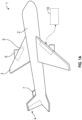
FIG. 1A shows an aircraft according to an embodiment; -
FIG. 1B shows an air cycle machine (ACM) of the aircraft according to an embodiment; -
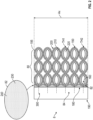
FIG. 2 shows aspects of an additively manufactured part with a lattice of beads manufactured of multiple plastic extrusions or printings to enable controlling of thermal expansion of the part; -
FIG. 3 shows a bead, with two thermoplastic polymer surfaces having CTE gradients that are different from each other at their interface and each one changes in the hoop or circumferential direction, at a temperature T1; -
FIG. 4 shows the bead ofFIG. 3 at a temperature T2>T1; -
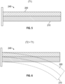
FIG. 5 shows an equivalent structure to the structures shown inFIGS. 3 and 4 , with two thermoplastic polymer surfaces having different coefficients of thermal expansion (CTE), at a temperature T1; and -
FIG. 6 shows the structure ofFIG. 5 at a temperature T2>T1. - A detailed description of one or more embodiments of the disclosed apparatus and method are presented herein by way of exemplification and not limitation with reference to the Figures.
-
FIG. 1A shows anaircraft 1 having afuselage 2 with a wing 3 and tail assembly 4, which may havecontrol surfaces 5. The wing 3 may include anengine 6, such as a gas turbine engine, and an auxiliary power unit 7 may be disposed at the tail assembly 4. Theaircraft 1 may have anair cycle machine 10.FIG. 1B shows additional details of the air cycle machine (ACM) 10. The ACM 10 may include various components or parts, generally referenced as 8. For example, an outer case 11 has aninlet housing 12 of acompressor inlet 14, and a motorcooling supply port 16. Downstream of theinlet housing 12 is aFOD screen 18. Atie rod 20 is surrounded by acompressor rotor 22. A diffusor rotor shroud (or shroud) 24 and an addheat housing 26 of the outer case 11 surround an addheat supply 28. The addheat housing 26 is connected to the outer case 11 via aforward frame member 25. Exterior to the addheat housing 26 is abackup ring 30 supporting a drive ring bearing 32. The drive ring bearing 32 is structurally coupled to a drive ring 34 andpinion 35. The ACM 10 includes a diffuser vane 36 and avariable diffusor actuator 40. Downstream of thecompressor rotor 22 is aninboard plate 42 structurally coupled to abacking plate 44. Anoutlet housing 46 of the outer case 11 defines acompressor outlet 48. Thecompressor outlet 48 is secured with abolt ring 50 to anintermediate frame member 52 of the ACM case 11. Arotor shaft 54 and aftthrust bearing shaft 56 are supported by journal bearings and asleeve 58. The journal bearing andsleeve 58 are supported by the case 11 via, e.g., theintermediate frame member 52 and anaft frame member 53. Thetie rod 20 is supported over therotor shaft 54 by atie rod support 60. The ACM case 11 defines a bearing andmotor cooling outlet 62. Amotor cooling inlet 64 is defined at anaft motor housing 66. Surrounding thethrust shaft 56 arethrust bearings 68. Athrust plate 70 is located at the aft end of the ACM 10. The aft end of the ACM 10 also defines a bearingcooling inlet 72 and includes lead wires and acover plate 74. Between themotor cooling inlet 64 andoutlet 62 is amotor stator 76 androtor 78. - As will be discussed in greater detail below, any part 8 of the ACM 10 may be additively manufactured of different thermoplastic polymers (plastics) having different coefficients of thermal expansion (CTE), and plated in metal.
- Turning to
FIG. 2 , the part 8 may be additively manufactured to include abase 80 that extends from abottom 150 of the part 8 to a first intermediate location 160 in a thickness direction. A discrete area Ax of the part 8 is shown, but the embodiments are not limited to any particular area of the part 8. Alower support section 82 is disposed over thebase 80 in the thickness direction. Thelower support section 82 extends from the first intermediate location 160 to a secondintermediate location 180. Anupper support section 84 is disposed over thelower support section 82. Theupper support section 84 extends from the secondintermediate location 180 to a top 190. - The part 8 may be formed by utilizing first and second thermoplastic polymers, having differing CTEs, to build up, layer by layer,
beads 195 formed of first (or outer) and second (or inner) thermoplastic polymer surfaces 200, 210. A void 220 is defined within theinner surface 210 of each of thebeads 195. - The
lower support section 82 is a mixture of athird plastic 230 and acatalyst 240 compound that includes metal. The catalyst may be palladium(II) chloride (PdCl2). Theupper support section 84 is a metal plating that is formed via electrolysis deposition so that the plating may be Pd. In one embodiment, the firstthermoplastic polymer surface 200 is acrylonitrile butadiene styrene (ABS). In one embodiment, the first and second thermoplastic polymer surfaces 200, 210 are the same as each other. In one embodiment, all of the utilized plastic in the part 8 can be the same thermoplastic polymer, such as ABS. - As shown in
FIG. 2 , thebeads 195 may be formed as lattice ofinterconnected beads 195 that have an oval shape, though other shapes are within the scope of the disclosure. Thebeads 195 are micro-pattern elements. The firstthermoplastic polymer surface 200 may form the outer bead surface 202 and the secondthermoplastic polymer surface 210 may form the inner bead surface 212. Thevoid 220 is located in the center of eachbead 195. The outer bead surface 202 has first thickness TH1 and the inner bead surface 212 has a second thickness TH2 that is greater than the first thickness TH1. - The base 80 may include a reinforcing fibers 330 that extend at least partially through ones of the
beads 195, from a location adjacent to thelower support section 82, extending through thelower support section 82, and extending at least partially thorough theupper support section 84. Thefibers 300 may serve various purposes, including functioning as anchors between the layers of thebase 80 and stabilizing the base 80 to prevent cracking. - The resulting configuration is capable of controlling thermal expansion and contraction of the part 8. As shown in
FIG. 3 thebeads 195 may have a composition gradients across hoop-shapedwalls 50, having anouter surface 52, aninner surface 54, to define first throughfourth perimeter segments segments bead 195. Theinner portion 205 of the first andsecond perimeter segments outer portion 215 of the first andsecond perimeter segments inner portion 205 of the third andfourth perimeter segments outer portion 215 of the third andfourth perimeter segments entire bead 195 may be formed of a single material that is formed to provide the desired CTE gradient. -
FIG. 3 shows abead 195 is shown at temperature T1, and inFIG. 4 at temperature T2>T1, thebase 80 has a controlled thermal explanation due to different CTEs and formation of the first (outer) and second (inner) thermoplastic polymer surfaces 200, 210 in thebase 80. More specifically, regardingFIG. 3 , thebead 195 is shown in which both the firstthermoplastic polymer surface 200 and secondthermoplastic polymer surface 210, i.e., the outer and inner surfaces, are also formed of CTEs that define gradients. The firstthermoplastic polymer surface 200 has a first CTE gradient CTE(Δ1) and the secondthermoplastic polymer surface 210 has a second CTE gradient CTE(Δ2). The gradients are formed such that they are different from each other at theirradial interface 360 and each one changes in the hoop or circumferential direction. When the temperature is increased from T1 to T2, the resulting controlled bend of thebase 80 is shown inFIG. 4 . As shown, thebead 195 has an oval or elliptical shape with a long and a narrow axis A1, A2, and, at temperature T2, thebead 195 becomes compressed along its narrow axis A2 due to the controlled deformation. InFIGS. 3 and 4 , thebead 195 is formed with a gradient of thermal expansion inside of the first and second thermoplastic polymer surfaces 200, 210, i.e., the outer and inner surfaces, to control the effect of the temperature changes. - It is to be appreciated that the
outer surface 200 of eachbead 195 may be formed with a combination of the first and second materials to provide the circumferential CTE gradient along the outer surface. For example, along theouter surface 200, polar opposite sides of thebeads 195 may be formed of the first material while polar middle sides of thebeads 195 may be formed of the first material. Theinner surface 210 of eachbead 195 also may be formed with a combination of the first and second materials that is the reverse of theouter surface 200, to provide the circumferential CTE gradient along theinner surface 210 as well as a radial CTE gradient around thebead 195. -
FIGS. 5 and 6 show anequivalent structure 248 to the structures shown inFIGS. 3 and 4 . Specifically, the first and second thermoplastic polymer surfaces 200, 210 are at a temperature T1 inFIG. 5 , and T2 that is greater than T1 inFIG. 6 . The controlled thermal expansion shown inFIG. 6 results from the thermoplastic polymer surfaces being integrally connected. That is, the first and second thermoplastic polymer surfaces 200, 210 bend together in a predictable and controlled way. That is, the controlled thermal expansion of the first and second thermoplastic polymer surfaces 200, 210 in the disclose embodiments prevents the metal plating of theupper support section 84 from breaking off the part 8. - Thus, the embodiments provide a part 8 made of plastic, which results in a cost reduction compared with making the part 8 from more exotic materials. The part 8 is abrasion resistant, and is not prone to static electric charging. The part 8 is designed for optimizing thermal deflections, to reduce induced stress and weight, and increase performance. Different thermal expansion characteristics may be obtained using two different thermoplastic polymers in the additive manufacturing process. Alternatively, as discussed below, the same material may be utilized with fillings such as metallic, carbon, or Kevlar fibers in the additive manufacturing process.
- The terminology used herein is for the purpose of describing particular embodiments only and is not intended to be limiting of the present disclosure. As used herein, the singular forms "a", "an" and "the" are intended to include the plural forms as well, unless the context clearly indicates otherwise. It will be further understood that the terms "comprises" and/or "comprising," when used in this specification, specify the presence of stated features, integers, steps, operations, elements, and/or components, but do not preclude the presence or addition of one or more other features, integers, steps, operations, element components, and/or groups thereof.
- Those of skill in the art will appreciate that various example embodiments are shown and described herein, each having certain features in the particular embodiments, but the present disclosure is not thus limited. Rather, the present disclosure can be modified to incorporate any number of variations, alterations, substitutions, combinations, sub-combinations, or equivalent arrangements not heretofore described, but which are commensurate with the scope of the present disclosure. Additionally, while various embodiments of the present disclosure have been described, it is to be understood that aspects of the present disclosure may include only some of the described embodiments. Accordingly, the present disclosure is not to be seen as limited by the foregoing description, but is only limited by the scope of the appended claims.
Claims (11)
- A component, comprising:a base (80) having beads (195) formed of with first and second thermoplastic polymers, respectively having first and second coefficients of thermal expansion (CTE), where each of the beads (195) has an outer surface (200) and an inner surface (210) that abut each other;a lower support section (82) formed on the base (80), having a mixture of a third thermoplastic polymer and a catalyst formed with metal;an upper support section (84) on the component, formed on the lower support section (82) via electrolysis deposition, a metallic coating, to thereby control thermal expansion and contraction of the component; andreinforcement fibers embedded the base (80), the lower support section (82) and the upper support section (84).
- The component of claim 1, wherein the first and second CTEs differ from each other.
- The component of claim 1 or 2, wherein:
the beads (195) are formed as an interconnected lattice, and wherein a void is formed in a center of each of the beads (195). - The component of any preceding claim, wherein:
the fibers extend at least partially through ones of the beads (195), from a location adjacent to the lower support section (82), extending through the lower support section (82), and the fibers extend at least partially thorough the upper support section (84). - The component of claim 3, wherein:the outer surface (200) is formed to provide a first CTE gradient; andprinting the inner surface (210) is formed to provide a second CTE gradient.
- The component of claim 5, wherein:
the first and second CTE gradients are opposite of each other to form a radial CTE gradient. - The component of any preceding claim, wherein the first and second thermoplastic polymers are the same as each other.
- The component of any preceding claim, wherein the first thermoplastic polymer is Acrylonitrile butadiene styrene (ABS).
- The component of any preceding claim, wherein the catalyst is palladium(II) chloride (PdCl2).
- The component of any preceding claim, wherein the component is formed via stereolithography (SLA) or fused deposition modeling (FDM).
- An air cycle machine of an aircraft, comprising the component of claim 1.
Applications Claiming Priority (1)
| Application Number | Priority Date | Filing Date | Title |
|---|---|---|---|
| US18/464,147 US12162606B1 (en) | 2023-09-08 | 2023-09-08 | Metal plated plastic ACM part with internal thermally adaptive structure |
Publications (1)
| Publication Number | Publication Date |
|---|---|
| EP4520529A1 true EP4520529A1 (en) | 2025-03-12 |
Family
ID=92538774
Family Applications (1)
| Application Number | Title | Priority Date | Filing Date |
|---|---|---|---|
| EP24196219.0A Pending EP4520529A1 (en) | 2023-09-08 | 2024-08-23 | Metal plated plastic acm part with internal thermally adaptive structure |
Country Status (2)
| Country | Link |
|---|---|
| US (1) | US12162606B1 (en) |
| EP (1) | EP4520529A1 (en) |
Families Citing this family (1)
| Publication number | Priority date | Publication date | Assignee | Title |
|---|---|---|---|---|
| US12384515B2 (en) * | 2023-09-08 | 2025-08-12 | Hamilton Sundstrand Corporation | Airfoil formed of thermally adaptive materials and a thermoelectric junction |
Citations (1)
| Publication number | Priority date | Publication date | Assignee | Title |
|---|---|---|---|---|
| US20230142146A1 (en) * | 2021-11-05 | 2023-05-11 | Hamilton Sundstrand Corporation | Articles having thermally controlled microstructure and methods of manufacture thereof |
Family Cites Families (40)
| Publication number | Priority date | Publication date | Assignee | Title |
|---|---|---|---|---|
| DE2737248C2 (en) | 1977-08-18 | 1985-09-19 | MTU Motoren- und Turbinen-Union München GmbH, 8000 München | High strength component with a complex geometric shape and process for its manufacture |
| CA1322876C (en) * | 1986-01-22 | 1993-10-12 | Tadao Inabata | Light metallic composite material and method of producing thereof |
| US5230850A (en) | 1991-05-16 | 1993-07-27 | Lewis Raymond O | Fan blade reinforcement using bonded hollow spheres |
| US6499952B1 (en) | 1997-02-28 | 2002-12-31 | The Boeing Company | Shape memory alloy device and control method |
| DE19742314C2 (en) | 1997-09-25 | 2000-06-21 | Daimler Chrysler Ag | Supporting structure |
| US7579069B2 (en) * | 2003-11-06 | 2009-08-25 | International Business Machines Corporation | Negative coefficient of thermal expansion particles and method of forming the same |
| US7854467B2 (en) | 2004-11-05 | 2010-12-21 | General Motors Corporation | Airflow control devices based on active materials |
| GB0525799D0 (en) | 2005-12-20 | 2006-01-25 | Rolls Royce Plc | Lightweight components |
| WO2008035293A2 (en) | 2006-09-20 | 2008-03-27 | Koninklijke Philips Electronics N.V. | A micro-fluidic device for the use in biochips or biosystems |
| US7770959B2 (en) | 2006-10-30 | 2010-08-10 | Gm Global Technology Operations, Inc. | Door actuation systems using active materials |
| US20080302024A1 (en) | 2007-06-05 | 2008-12-11 | Gm Global Technology Operations, Inc. | Tunable impedance load-bearing structures |
| US7967568B2 (en) | 2007-09-21 | 2011-06-28 | Siemens Energy, Inc. | Gas turbine component with reduced cooling air requirement |
| GB2472053A (en) | 2009-07-23 | 2011-01-26 | Rolls Royce Plc | Aircraft and engine deicing apparatus |
| JP2011148037A (en) | 2010-01-21 | 2011-08-04 | Tokai Rubber Ind Ltd | Actuator using shape memory polymer, and method of controlling the same |
| US9796159B2 (en) | 2011-04-14 | 2017-10-24 | The United States Of America As Represented By The Administrator Of Nasa | Electric field activated shape memory polymer composite |
| KR101333048B1 (en) | 2011-07-08 | 2013-11-26 | 울산대학교 산학협력단 | Actuator using shape memory alloy |
| US9181933B2 (en) | 2012-12-10 | 2015-11-10 | Alcatel Lucent | Temperature control device with a passive thermal feedback control valve |
| US9650898B2 (en) | 2012-12-27 | 2017-05-16 | United Technologies Corporation | Airfoil with variable profile responsive to thermal conditions |
| US9631268B2 (en) | 2013-02-26 | 2017-04-25 | The Boeing Company | Methods and systems for shape memory alloy structures |
| JP6058809B2 (en) | 2013-06-28 | 2017-01-11 | ヘルムホルツ−ツェントルム ゲーストハハト ツェントルム フュアー マテリアル ウント キュステンフォルシュンク ゲーエムベーハー | Method for making bidirectional shape memory actuator and method of using the same |
| WO2015006428A1 (en) | 2013-07-09 | 2015-01-15 | United Technologies Corporation | Interlocked plated polymers |
| US9719536B2 (en) | 2014-07-03 | 2017-08-01 | The Boeing Company | Assemblies including shape memory alloy fittings and composite structural members |
| US9981421B2 (en) | 2014-07-16 | 2018-05-29 | The Boeing Company | Adaptive composite structure using shape memory alloys |
| EP3112055B1 (en) | 2015-07-01 | 2020-12-02 | Ansaldo Energia IP UK Limited | Method for manufacturing a metal part with bi-metallic characteristic |
| US9784126B2 (en) | 2015-12-14 | 2017-10-10 | Hamilton Sundstrand Corporation | Variable-sized cooling air flow path |
| US9897078B2 (en) | 2016-05-24 | 2018-02-20 | The Boeing Company | Bi-directional rotary shape memory alloy element actuator assemblies, and systems and methods including the same |
| US11008943B2 (en) | 2016-08-31 | 2021-05-18 | Unison Industries, Llc | Fan casing assembly with cooler and method of moving |
| US10533558B2 (en) | 2016-12-21 | 2020-01-14 | Saudi Arabian Oil Company | Centrifugal pump with adaptive pump stages |
| CA3097190A1 (en) * | 2017-06-14 | 2018-12-20 | The Royal Institution For The Advancement Of Learning/Mcgill University | Lattice metamaterial having programed thermal expansion |
| CN110100385A (en) | 2017-11-27 | 2019-08-06 | 松下知识产权经营株式会社 | Actuator devices |
| WO2019108203A1 (en) | 2017-11-30 | 2019-06-06 | Siemens Aktiengesellschaft | Hybrid ceramic matrix composite components with intermediate cushion structure |
| EP3784822A1 (en) * | 2018-04-24 | 2021-03-03 | CSEM Centre Suisse d'Electronique et de Microtechnique SA - Recherche et Développement | Method of metal plating of polymer-containing substrates |
| US11167836B2 (en) | 2018-06-21 | 2021-11-09 | Sierra Nevada Corporation | Devices and methods to attach composite core to a surrounding structure |
| US10976119B2 (en) | 2018-07-30 | 2021-04-13 | The Boeing Company | Heat transfer devices and methods of transfering heat |
| US11192333B2 (en) * | 2018-10-25 | 2021-12-07 | Honda Motor Co., Ltd. | Embedded metal transition for joining fiber reinforced polymers and metallic structures |
| US10982783B2 (en) | 2018-10-30 | 2021-04-20 | Hamilton Sunstrand Corporation | Variable flow controlled diaphragm valve based on shape memory alloy |
| US11359287B2 (en) | 2019-08-01 | 2022-06-14 | The Boeing Company | Adhesion between polymer substrates and autocatalytic plates |
| US11692049B2 (en) | 2020-09-18 | 2023-07-04 | Ford Global Technologies, Llc | Additively manufactured thermoset polymers for metal plating and metal plated parts formed therefrom |
| US11248592B1 (en) | 2021-03-26 | 2022-02-15 | Toyota Motor Engineering & Manufacturing North America, Inc. | Shape memory alloy enhanced bi-stable actuator |
| US11668316B1 (en) * | 2022-01-07 | 2023-06-06 | Hamilton Sundstrand Corporation | Rotor formed of multiple metals |
-
2023
- 2023-09-08 US US18/464,147 patent/US12162606B1/en active Active
-
2024
- 2024-08-23 EP EP24196219.0A patent/EP4520529A1/en active Pending
Patent Citations (1)
| Publication number | Priority date | Publication date | Assignee | Title |
|---|---|---|---|---|
| US20230142146A1 (en) * | 2021-11-05 | 2023-05-11 | Hamilton Sundstrand Corporation | Articles having thermally controlled microstructure and methods of manufacture thereof |
Also Published As
| Publication number | Publication date |
|---|---|
| US12162606B1 (en) | 2024-12-10 |
Similar Documents
| Publication | Publication Date | Title |
|---|---|---|
| US11268526B2 (en) | Plated polymer fan | |
| US20160160869A1 (en) | Plated polymer compressor | |
| EP4411108B1 (en) | Metal plated additively manufactured plastic rotors and their method of manufacturing | |
| US12162606B1 (en) | Metal plated plastic ACM part with internal thermally adaptive structure | |
| US11181074B2 (en) | Variable area fan nozzle with wall thickness distribution | |
| EP4411114B1 (en) | Metal plated additively manufactured plastic seal plates and their method of manufacturing | |
| EP4497569B1 (en) | Metal plated additively manufactured plastic acm housings with internal thermally adaptive structure | |
| EP4497568A1 (en) | Method for forming a shaft for an air cycle machine | |
| EP4506150A1 (en) | Metal plated additively manufactured plastic acm rotors with internal thermally adaptive structure | |
| EP4497570A1 (en) | Metal plated additively manufactured plastic acm shrouds with internal thermally adaptive structure | |
| EP2941540B1 (en) | Airfoil with variable profile responsive to thermal conditions | |
| EP4497521A1 (en) | Metal plated additively manufactured plastic acm seal plates with internal thermally adaptive structure | |
| EP4512937A2 (en) | Metal plating retention on additively manufacture plastic parts for an aircraft | |
| EP4411107B1 (en) | Metal plated additively manufactured plastic shafts and their method of manufacturing | |
| EP4411110B1 (en) | Metal plated additively manufactured plastic rotor shrouds and their method of manufacturing | |
| EP4411109A2 (en) | Metal plated additively manufactured plastic housing | |
| EP2971595B1 (en) | Variable area fan nozzle with wall thickness distribution | |
| CA3222213A1 (en) | Electroless deposited coating with stiffeners |
Legal Events
| Date | Code | Title | Description |
|---|---|---|---|
| PUAI | Public reference made under article 153(3) epc to a published international application that has entered the european phase |
Free format text: ORIGINAL CODE: 0009012 |
|
| STAA | Information on the status of an ep patent application or granted ep patent |
Free format text: STATUS: THE APPLICATION HAS BEEN PUBLISHED |
|
| AK | Designated contracting states |
Kind code of ref document: A1 Designated state(s): AL AT BE BG CH CY CZ DE DK EE ES FI FR GB GR HR HU IE IS IT LI LT LU LV MC ME MK MT NL NO PL PT RO RS SE SI SK SM TR |
|
| STAA | Information on the status of an ep patent application or granted ep patent |
Free format text: STATUS: REQUEST FOR EXAMINATION WAS MADE |
|
| 17P | Request for examination filed |
Effective date: 20250908 |
|
| GRAP | Despatch of communication of intention to grant a patent |
Free format text: ORIGINAL CODE: EPIDOSNIGR1 |
|
| STAA | Information on the status of an ep patent application or granted ep patent |
Free format text: STATUS: GRANT OF PATENT IS INTENDED |
|
| INTG | Intention to grant announced |
Effective date: 20260313 |