EP4520525A1 - Components having coating systems comprising highly porous layers and methods for forming the coating systems - Google Patents
Components having coating systems comprising highly porous layers and methods for forming the coating systems Download PDFInfo
- Publication number
- EP4520525A1 EP4520525A1 EP24194143.4A EP24194143A EP4520525A1 EP 4520525 A1 EP4520525 A1 EP 4520525A1 EP 24194143 A EP24194143 A EP 24194143A EP 4520525 A1 EP4520525 A1 EP 4520525A1
- Authority
- EP
- European Patent Office
- Prior art keywords
- substrate
- tbc
- microstructure
- mixture
- ceramic
- Prior art date
- Legal status (The legal status is an assumption and is not a legal conclusion. Google has not performed a legal analysis and makes no representation as to the accuracy of the status listed.)
- Pending
Links
Images


Classifications
-
- C—CHEMISTRY; METALLURGY
- C23—COATING METALLIC MATERIAL; COATING MATERIAL WITH METALLIC MATERIAL; CHEMICAL SURFACE TREATMENT; DIFFUSION TREATMENT OF METALLIC MATERIAL; COATING BY VACUUM EVAPORATION, BY SPUTTERING, BY ION IMPLANTATION OR BY CHEMICAL VAPOUR DEPOSITION, IN GENERAL; INHIBITING CORROSION OF METALLIC MATERIAL OR INCRUSTATION IN GENERAL
- C23C—COATING METALLIC MATERIAL; COATING MATERIAL WITH METALLIC MATERIAL; SURFACE TREATMENT OF METALLIC MATERIAL BY DIFFUSION INTO THE SURFACE, BY CHEMICAL CONVERSION OR SUBSTITUTION; COATING BY VACUUM EVAPORATION, BY SPUTTERING, BY ION IMPLANTATION OR BY CHEMICAL VAPOUR DEPOSITION, IN GENERAL
- C23C4/00—Coating by spraying the coating material in the molten state, e.g. by flame, plasma or electric discharge
- C23C4/18—After-treatment
-
- C—CHEMISTRY; METALLURGY
- C04—CEMENTS; CONCRETE; ARTIFICIAL STONE; CERAMICS; REFRACTORIES
- C04B—LIME, MAGNESIA; SLAG; CEMENTS; COMPOSITIONS THEREOF, e.g. MORTARS, CONCRETE OR LIKE BUILDING MATERIALS; ARTIFICIAL STONE; CERAMICS; REFRACTORIES; TREATMENT OF NATURAL STONE
- C04B37/00—Joining burned ceramic articles with other burned ceramic articles or other articles by heating
- C04B37/003—Joining burned ceramic articles with other burned ceramic articles or other articles by heating by means of an interlayer consisting of a combination of materials selected from glass, or ceramic material with metals, metal oxides or metal salts
-
- B—PERFORMING OPERATIONS; TRANSPORTING
- B32—LAYERED PRODUCTS
- B32B—LAYERED PRODUCTS, i.e. PRODUCTS BUILT-UP OF STRATA OF FLAT OR NON-FLAT, e.g. CELLULAR OR HONEYCOMB, FORM
- B32B18/00—Layered products essentially comprising ceramics, e.g. refractory products
-
- C—CHEMISTRY; METALLURGY
- C04—CEMENTS; CONCRETE; ARTIFICIAL STONE; CERAMICS; REFRACTORIES
- C04B—LIME, MAGNESIA; SLAG; CEMENTS; COMPOSITIONS THEREOF, e.g. MORTARS, CONCRETE OR LIKE BUILDING MATERIALS; ARTIFICIAL STONE; CERAMICS; REFRACTORIES; TREATMENT OF NATURAL STONE
- C04B35/00—Shaped ceramic products characterised by their composition; Ceramics compositions; Processing powders of inorganic compounds preparatory to the manufacturing of ceramic products
- C04B35/01—Shaped ceramic products characterised by their composition; Ceramics compositions; Processing powders of inorganic compounds preparatory to the manufacturing of ceramic products based on oxide ceramics
- C04B35/16—Shaped ceramic products characterised by their composition; Ceramics compositions; Processing powders of inorganic compounds preparatory to the manufacturing of ceramic products based on oxide ceramics based on silicates other than clay
-
- C—CHEMISTRY; METALLURGY
- C04—CEMENTS; CONCRETE; ARTIFICIAL STONE; CERAMICS; REFRACTORIES
- C04B—LIME, MAGNESIA; SLAG; CEMENTS; COMPOSITIONS THEREOF, e.g. MORTARS, CONCRETE OR LIKE BUILDING MATERIALS; ARTIFICIAL STONE; CERAMICS; REFRACTORIES; TREATMENT OF NATURAL STONE
- C04B35/00—Shaped ceramic products characterised by their composition; Ceramics compositions; Processing powders of inorganic compounds preparatory to the manufacturing of ceramic products
- C04B35/622—Forming processes; Processing powders of inorganic compounds preparatory to the manufacturing of ceramic products
- C04B35/62222—Forming processes; Processing powders of inorganic compounds preparatory to the manufacturing of ceramic products obtaining ceramic coatings
-
- C—CHEMISTRY; METALLURGY
- C04—CEMENTS; CONCRETE; ARTIFICIAL STONE; CERAMICS; REFRACTORIES
- C04B—LIME, MAGNESIA; SLAG; CEMENTS; COMPOSITIONS THEREOF, e.g. MORTARS, CONCRETE OR LIKE BUILDING MATERIALS; ARTIFICIAL STONE; CERAMICS; REFRACTORIES; TREATMENT OF NATURAL STONE
- C04B38/00—Porous mortars, concrete, artificial stone or ceramic ware; Preparation thereof
- C04B38/06—Porous mortars, concrete, artificial stone or ceramic ware; Preparation thereof by burning-out added substances by burning natural expanding materials or by sublimating or melting out added substances
- C04B38/0615—Porous mortars, concrete, artificial stone or ceramic ware; Preparation thereof by burning-out added substances by burning natural expanding materials or by sublimating or melting out added substances the burned-out substance being a monolitic element having approximately the same dimensions as the final article, e.g. a porous polyurethane sheet or a prepreg obtained by bonding together resin particles
-
- C—CHEMISTRY; METALLURGY
- C23—COATING METALLIC MATERIAL; COATING MATERIAL WITH METALLIC MATERIAL; CHEMICAL SURFACE TREATMENT; DIFFUSION TREATMENT OF METALLIC MATERIAL; COATING BY VACUUM EVAPORATION, BY SPUTTERING, BY ION IMPLANTATION OR BY CHEMICAL VAPOUR DEPOSITION, IN GENERAL; INHIBITING CORROSION OF METALLIC MATERIAL OR INCRUSTATION IN GENERAL
- C23C—COATING METALLIC MATERIAL; COATING MATERIAL WITH METALLIC MATERIAL; SURFACE TREATMENT OF METALLIC MATERIAL BY DIFFUSION INTO THE SURFACE, BY CHEMICAL CONVERSION OR SUBSTITUTION; COATING BY VACUUM EVAPORATION, BY SPUTTERING, BY ION IMPLANTATION OR BY CHEMICAL VAPOUR DEPOSITION, IN GENERAL
- C23C24/00—Coating starting from inorganic powder
- C23C24/02—Coating starting from inorganic powder by application of pressure only
- C23C24/04—Impact or kinetic deposition of particles
-
- C—CHEMISTRY; METALLURGY
- C23—COATING METALLIC MATERIAL; COATING MATERIAL WITH METALLIC MATERIAL; CHEMICAL SURFACE TREATMENT; DIFFUSION TREATMENT OF METALLIC MATERIAL; COATING BY VACUUM EVAPORATION, BY SPUTTERING, BY ION IMPLANTATION OR BY CHEMICAL VAPOUR DEPOSITION, IN GENERAL; INHIBITING CORROSION OF METALLIC MATERIAL OR INCRUSTATION IN GENERAL
- C23C—COATING METALLIC MATERIAL; COATING MATERIAL WITH METALLIC MATERIAL; SURFACE TREATMENT OF METALLIC MATERIAL BY DIFFUSION INTO THE SURFACE, BY CHEMICAL CONVERSION OR SUBSTITUTION; COATING BY VACUUM EVAPORATION, BY SPUTTERING, BY ION IMPLANTATION OR BY CHEMICAL VAPOUR DEPOSITION, IN GENERAL
- C23C24/00—Coating starting from inorganic powder
- C23C24/08—Coating starting from inorganic powder by application of heat or pressure and heat
- C23C24/10—Coating starting from inorganic powder by application of heat or pressure and heat with intermediate formation of a liquid phase in the layer
-
- C—CHEMISTRY; METALLURGY
- C23—COATING METALLIC MATERIAL; COATING MATERIAL WITH METALLIC MATERIAL; CHEMICAL SURFACE TREATMENT; DIFFUSION TREATMENT OF METALLIC MATERIAL; COATING BY VACUUM EVAPORATION, BY SPUTTERING, BY ION IMPLANTATION OR BY CHEMICAL VAPOUR DEPOSITION, IN GENERAL; INHIBITING CORROSION OF METALLIC MATERIAL OR INCRUSTATION IN GENERAL
- C23C—COATING METALLIC MATERIAL; COATING MATERIAL WITH METALLIC MATERIAL; SURFACE TREATMENT OF METALLIC MATERIAL BY DIFFUSION INTO THE SURFACE, BY CHEMICAL CONVERSION OR SUBSTITUTION; COATING BY VACUUM EVAPORATION, BY SPUTTERING, BY ION IMPLANTATION OR BY CHEMICAL VAPOUR DEPOSITION, IN GENERAL
- C23C28/00—Coating for obtaining at least two superposed coatings either by methods not provided for in a single one of groups C23C2/00 - C23C26/00 or by combinations of methods provided for in subclasses C23C and C25C or C25D
- C23C28/30—Coatings combining at least one metallic layer and at least one inorganic non-metallic layer
- C23C28/34—Coatings combining at least one metallic layer and at least one inorganic non-metallic layer including at least one inorganic non-metallic material layer, e.g. metal carbide, nitride, boride, silicide layer and their mixtures, enamels, phosphates and sulphates
- C23C28/345—Coatings combining at least one metallic layer and at least one inorganic non-metallic layer including at least one inorganic non-metallic material layer, e.g. metal carbide, nitride, boride, silicide layer and their mixtures, enamels, phosphates and sulphates with at least one oxide layer
- C23C28/3455—Coatings combining at least one metallic layer and at least one inorganic non-metallic layer including at least one inorganic non-metallic material layer, e.g. metal carbide, nitride, boride, silicide layer and their mixtures, enamels, phosphates and sulphates with at least one oxide layer with a refractory ceramic layer, e.g. refractory metal oxide, ZrO2, rare earth oxides or a thermal barrier system comprising at least one refractory oxide layer
-
- C—CHEMISTRY; METALLURGY
- C23—COATING METALLIC MATERIAL; COATING MATERIAL WITH METALLIC MATERIAL; CHEMICAL SURFACE TREATMENT; DIFFUSION TREATMENT OF METALLIC MATERIAL; COATING BY VACUUM EVAPORATION, BY SPUTTERING, BY ION IMPLANTATION OR BY CHEMICAL VAPOUR DEPOSITION, IN GENERAL; INHIBITING CORROSION OF METALLIC MATERIAL OR INCRUSTATION IN GENERAL
- C23C—COATING METALLIC MATERIAL; COATING MATERIAL WITH METALLIC MATERIAL; SURFACE TREATMENT OF METALLIC MATERIAL BY DIFFUSION INTO THE SURFACE, BY CHEMICAL CONVERSION OR SUBSTITUTION; COATING BY VACUUM EVAPORATION, BY SPUTTERING, BY ION IMPLANTATION OR BY CHEMICAL VAPOUR DEPOSITION, IN GENERAL
- C23C28/00—Coating for obtaining at least two superposed coatings either by methods not provided for in a single one of groups C23C2/00 - C23C26/00 or by combinations of methods provided for in subclasses C23C and C25C or C25D
- C23C28/30—Coatings combining at least one metallic layer and at least one inorganic non-metallic layer
- C23C28/36—Coatings combining at least one metallic layer and at least one inorganic non-metallic layer including layers graded in composition or physical properties
-
- F—MECHANICAL ENGINEERING; LIGHTING; HEATING; WEAPONS; BLASTING
- F01—MACHINES OR ENGINES IN GENERAL; ENGINE PLANTS IN GENERAL; STEAM ENGINES
- F01D—NON-POSITIVE DISPLACEMENT MACHINES OR ENGINES, e.g. STEAM TURBINES
- F01D5/00—Blades; Blade-carrying members; Heating, heat-insulating, cooling or antivibration means on the blades or the members
- F01D5/12—Blades
- F01D5/28—Selecting particular materials; Particular measures relating thereto; Measures against erosion or corrosion
-
- C—CHEMISTRY; METALLURGY
- C04—CEMENTS; CONCRETE; ARTIFICIAL STONE; CERAMICS; REFRACTORIES
- C04B—LIME, MAGNESIA; SLAG; CEMENTS; COMPOSITIONS THEREOF, e.g. MORTARS, CONCRETE OR LIKE BUILDING MATERIALS; ARTIFICIAL STONE; CERAMICS; REFRACTORIES; TREATMENT OF NATURAL STONE
- C04B2111/00—Mortars, concrete or artificial stone or mixtures to prepare them, characterised by specific function, property or use
- C04B2111/00241—Physical properties of the materials not provided for elsewhere in C04B2111/00
- C04B2111/00405—Materials with a gradually increasing or decreasing concentration of ingredients or property from one layer to another
-
- C—CHEMISTRY; METALLURGY
- C04—CEMENTS; CONCRETE; ARTIFICIAL STONE; CERAMICS; REFRACTORIES
- C04B—LIME, MAGNESIA; SLAG; CEMENTS; COMPOSITIONS THEREOF, e.g. MORTARS, CONCRETE OR LIKE BUILDING MATERIALS; ARTIFICIAL STONE; CERAMICS; REFRACTORIES; TREATMENT OF NATURAL STONE
- C04B2111/00—Mortars, concrete or artificial stone or mixtures to prepare them, characterised by specific function, property or use
- C04B2111/00474—Uses not provided for elsewhere in C04B2111/00
- C04B2111/00482—Coating or impregnation materials
-
- C—CHEMISTRY; METALLURGY
- C04—CEMENTS; CONCRETE; ARTIFICIAL STONE; CERAMICS; REFRACTORIES
- C04B—LIME, MAGNESIA; SLAG; CEMENTS; COMPOSITIONS THEREOF, e.g. MORTARS, CONCRETE OR LIKE BUILDING MATERIALS; ARTIFICIAL STONE; CERAMICS; REFRACTORIES; TREATMENT OF NATURAL STONE
- C04B2111/00—Mortars, concrete or artificial stone or mixtures to prepare them, characterised by specific function, property or use
- C04B2111/00474—Uses not provided for elsewhere in C04B2111/00
- C04B2111/00982—Uses not provided for elsewhere in C04B2111/00 as construction elements for space vehicles or aeroplanes
-
- C—CHEMISTRY; METALLURGY
- C04—CEMENTS; CONCRETE; ARTIFICIAL STONE; CERAMICS; REFRACTORIES
- C04B—LIME, MAGNESIA; SLAG; CEMENTS; COMPOSITIONS THEREOF, e.g. MORTARS, CONCRETE OR LIKE BUILDING MATERIALS; ARTIFICIAL STONE; CERAMICS; REFRACTORIES; TREATMENT OF NATURAL STONE
- C04B2111/00—Mortars, concrete or artificial stone or mixtures to prepare them, characterised by specific function, property or use
- C04B2111/20—Resistance against chemical, physical or biological attack
- C04B2111/28—Fire resistance, i.e. materials resistant to accidental fires or high temperatures
-
- C—CHEMISTRY; METALLURGY
- C04—CEMENTS; CONCRETE; ARTIFICIAL STONE; CERAMICS; REFRACTORIES
- C04B—LIME, MAGNESIA; SLAG; CEMENTS; COMPOSITIONS THEREOF, e.g. MORTARS, CONCRETE OR LIKE BUILDING MATERIALS; ARTIFICIAL STONE; CERAMICS; REFRACTORIES; TREATMENT OF NATURAL STONE
- C04B2235/00—Aspects relating to ceramic starting mixtures or sintered ceramic products
- C04B2235/02—Composition of constituents of the starting material or of secondary phases of the final product
- C04B2235/30—Constituents and secondary phases not being of a fibrous nature
- C04B2235/32—Metal oxides, mixed metal oxides, or oxide-forming salts thereof, e.g. carbonates, nitrates, (oxy)hydroxides, chlorides
- C04B2235/3224—Rare earth oxide or oxide forming salts thereof, e.g. scandium oxide
-
- C—CHEMISTRY; METALLURGY
- C04—CEMENTS; CONCRETE; ARTIFICIAL STONE; CERAMICS; REFRACTORIES
- C04B—LIME, MAGNESIA; SLAG; CEMENTS; COMPOSITIONS THEREOF, e.g. MORTARS, CONCRETE OR LIKE BUILDING MATERIALS; ARTIFICIAL STONE; CERAMICS; REFRACTORIES; TREATMENT OF NATURAL STONE
- C04B2235/00—Aspects relating to ceramic starting mixtures or sintered ceramic products
- C04B2235/02—Composition of constituents of the starting material or of secondary phases of the final product
- C04B2235/30—Constituents and secondary phases not being of a fibrous nature
- C04B2235/32—Metal oxides, mixed metal oxides, or oxide-forming salts thereof, e.g. carbonates, nitrates, (oxy)hydroxides, chlorides
- C04B2235/3224—Rare earth oxide or oxide forming salts thereof, e.g. scandium oxide
- C04B2235/3225—Yttrium oxide or oxide-forming salts thereof
-
- C—CHEMISTRY; METALLURGY
- C04—CEMENTS; CONCRETE; ARTIFICIAL STONE; CERAMICS; REFRACTORIES
- C04B—LIME, MAGNESIA; SLAG; CEMENTS; COMPOSITIONS THEREOF, e.g. MORTARS, CONCRETE OR LIKE BUILDING MATERIALS; ARTIFICIAL STONE; CERAMICS; REFRACTORIES; TREATMENT OF NATURAL STONE
- C04B2235/00—Aspects relating to ceramic starting mixtures or sintered ceramic products
- C04B2235/02—Composition of constituents of the starting material or of secondary phases of the final product
- C04B2235/30—Constituents and secondary phases not being of a fibrous nature
- C04B2235/32—Metal oxides, mixed metal oxides, or oxide-forming salts thereof, e.g. carbonates, nitrates, (oxy)hydroxides, chlorides
- C04B2235/3224—Rare earth oxide or oxide forming salts thereof, e.g. scandium oxide
- C04B2235/3227—Lanthanum oxide or oxide-forming salts thereof
-
- C—CHEMISTRY; METALLURGY
- C04—CEMENTS; CONCRETE; ARTIFICIAL STONE; CERAMICS; REFRACTORIES
- C04B—LIME, MAGNESIA; SLAG; CEMENTS; COMPOSITIONS THEREOF, e.g. MORTARS, CONCRETE OR LIKE BUILDING MATERIALS; ARTIFICIAL STONE; CERAMICS; REFRACTORIES; TREATMENT OF NATURAL STONE
- C04B2235/00—Aspects relating to ceramic starting mixtures or sintered ceramic products
- C04B2235/02—Composition of constituents of the starting material or of secondary phases of the final product
- C04B2235/30—Constituents and secondary phases not being of a fibrous nature
- C04B2235/32—Metal oxides, mixed metal oxides, or oxide-forming salts thereof, e.g. carbonates, nitrates, (oxy)hydroxides, chlorides
- C04B2235/3224—Rare earth oxide or oxide forming salts thereof, e.g. scandium oxide
- C04B2235/3229—Cerium oxides or oxide-forming salts thereof
-
- C—CHEMISTRY; METALLURGY
- C04—CEMENTS; CONCRETE; ARTIFICIAL STONE; CERAMICS; REFRACTORIES
- C04B—LIME, MAGNESIA; SLAG; CEMENTS; COMPOSITIONS THEREOF, e.g. MORTARS, CONCRETE OR LIKE BUILDING MATERIALS; ARTIFICIAL STONE; CERAMICS; REFRACTORIES; TREATMENT OF NATURAL STONE
- C04B2235/00—Aspects relating to ceramic starting mixtures or sintered ceramic products
- C04B2235/70—Aspects relating to sintered or melt-casted ceramic products
- C04B2235/74—Physical characteristics
- C04B2235/77—Density
- C04B2235/775—Products showing a density-gradient
-
- C—CHEMISTRY; METALLURGY
- C04—CEMENTS; CONCRETE; ARTIFICIAL STONE; CERAMICS; REFRACTORIES
- C04B—LIME, MAGNESIA; SLAG; CEMENTS; COMPOSITIONS THEREOF, e.g. MORTARS, CONCRETE OR LIKE BUILDING MATERIALS; ARTIFICIAL STONE; CERAMICS; REFRACTORIES; TREATMENT OF NATURAL STONE
- C04B2237/00—Aspects relating to ceramic laminates or to joining of ceramic articles with other articles by heating
- C04B2237/30—Composition of layers of ceramic laminates or of ceramic or metallic articles to be joined by heating, e.g. Si substrates
- C04B2237/32—Ceramic
- C04B2237/34—Oxidic
- C04B2237/341—Silica or silicates
-
- C—CHEMISTRY; METALLURGY
- C04—CEMENTS; CONCRETE; ARTIFICIAL STONE; CERAMICS; REFRACTORIES
- C04B—LIME, MAGNESIA; SLAG; CEMENTS; COMPOSITIONS THEREOF, e.g. MORTARS, CONCRETE OR LIKE BUILDING MATERIALS; ARTIFICIAL STONE; CERAMICS; REFRACTORIES; TREATMENT OF NATURAL STONE
- C04B2237/00—Aspects relating to ceramic laminates or to joining of ceramic articles with other articles by heating
- C04B2237/30—Composition of layers of ceramic laminates or of ceramic or metallic articles to be joined by heating, e.g. Si substrates
- C04B2237/32—Ceramic
- C04B2237/38—Fiber or whisker reinforced
-
- C—CHEMISTRY; METALLURGY
- C04—CEMENTS; CONCRETE; ARTIFICIAL STONE; CERAMICS; REFRACTORIES
- C04B—LIME, MAGNESIA; SLAG; CEMENTS; COMPOSITIONS THEREOF, e.g. MORTARS, CONCRETE OR LIKE BUILDING MATERIALS; ARTIFICIAL STONE; CERAMICS; REFRACTORIES; TREATMENT OF NATURAL STONE
- C04B2237/00—Aspects relating to ceramic laminates or to joining of ceramic articles with other articles by heating
- C04B2237/50—Processing aspects relating to ceramic laminates or to the joining of ceramic articles with other articles by heating
- C04B2237/58—Forming a gradient in composition or in properties across the laminate or the joined articles
-
- C—CHEMISTRY; METALLURGY
- C04—CEMENTS; CONCRETE; ARTIFICIAL STONE; CERAMICS; REFRACTORIES
- C04B—LIME, MAGNESIA; SLAG; CEMENTS; COMPOSITIONS THEREOF, e.g. MORTARS, CONCRETE OR LIKE BUILDING MATERIALS; ARTIFICIAL STONE; CERAMICS; REFRACTORIES; TREATMENT OF NATURAL STONE
- C04B2237/00—Aspects relating to ceramic laminates or to joining of ceramic articles with other articles by heating
- C04B2237/50—Processing aspects relating to ceramic laminates or to the joining of ceramic articles with other articles by heating
- C04B2237/58—Forming a gradient in composition or in properties across the laminate or the joined articles
- C04B2237/586—Forming a gradient in composition or in properties across the laminate or the joined articles by joining layers or articles of the same composition but having different densities
-
- F—MECHANICAL ENGINEERING; LIGHTING; HEATING; WEAPONS; BLASTING
- F05—INDEXING SCHEMES RELATING TO ENGINES OR PUMPS IN VARIOUS SUBCLASSES OF CLASSES F01-F04
- F05B—INDEXING SCHEME RELATING TO WIND, SPRING, WEIGHT, INERTIA OR LIKE MOTORS, TO MACHINES OR ENGINES FOR LIQUIDS COVERED BY SUBCLASSES F03B, F03D AND F03G
- F05B2230/00—Manufacture
- F05B2230/90—Coating; Surface treatment
-
- F—MECHANICAL ENGINEERING; LIGHTING; HEATING; WEAPONS; BLASTING
- F05—INDEXING SCHEMES RELATING TO ENGINES OR PUMPS IN VARIOUS SUBCLASSES OF CLASSES F01-F04
- F05C—INDEXING SCHEME RELATING TO MATERIALS, MATERIAL PROPERTIES OR MATERIAL CHARACTERISTICS FOR MACHINES, ENGINES OR PUMPS OTHER THAN NON-POSITIVE-DISPLACEMENT MACHINES OR ENGINES
- F05C2253/00—Other material characteristics; Treatment of material
- F05C2253/12—Coating
Definitions
- the present invention generally relates to coating systems, and more particularly relates to components and methods for coating the components to produce coating systems thereon that include highly porous microstructures.
- a method in various embodiments, includes locating a first mixture within a mold cavity defined by inner surfaces of a mold, the first mixture including a ceramic material and a first polymeric foaming composition, retaining the first mixture within the mold cavity for a period of time sufficient to allow the first mixture to foam and cure and thereby produce a foam body having a shape defined by the mold cavity, performing a one or more heat treatments to remove non-ceramic materials from the foam body and sinter the ceramic material to produce a ceramic body, wherein a microstructure of the ceramic body is based on the first polymeric foaming composition, performing a machining process to modify a size and/or a shape of the ceramic body, and securing the ceramic body to a substrate of a component to define at least a portion of a thermal barrier coating (TBC) on the substrate.
- TBC thermal barrier coating
- a component for a gas turbine engine includes a substrate and a thermal barrier coating (TBC) having at least a first layer secured to a surface of the substrate.
- the first layer is formed of a ceramic material with a first microstructure that includes a plurality of interconnected unit cells having struts that have a relative density of greater than 98 percent and a closed cell porosity of 10 percent or greater.
- the TBC is secured to the substrate subsequent to formation of the TBC.
- embodiments of the present disclosure include components that have a coating system fixed and/or bonded to a substrate thereof, and manufacturing methods for providing the components.
- the component may be configured for use in a high temperature and/or high pressure environment, and the coating system may be a protective ceramic coating, such as an environmental barrier coating (EBC) and/or a thermal barrier coating (TBC).
- the coating system of the components include at least one layer comprising a highly porous microstructure that includes a rare-earth silicate, such as but not limited to ytterbium monosilicate (YbMS, Yb 2 SiO 5 ) and/or ytterbium disilicate (YbDS, Yb 2 Si 2 O 7 ).
- the coating systems may be capable of providing environmental and/or thermal protection at high temperatures, such as 2850 °F (about 1565 °C) or greater, such as 3100 °F (about 1705 °C) or greater.
- the components are not particularly limited to any size, shape, or application.
- the components may be used in any industry including, but not limited to, the automobile industry, the aerospace industry, the transportation industry, the power generation industry, the mining industry, etc.
- the components may be particularly suitable for use in a high temperature and/or high pressure environments including, but not limited to, power plants, mining, petroleum and oil refining, fracking, under water applications, deep sea applications, etc.
- the components may be any portion of a vehicle, aircraft, ship, train, etc.
- the components may be any portion of an engine or a motor, such as used for propulsion of a vehicle, aircraft, ship, train, etc.
- the components may be any portion of a gas turbine engine, such as an aircraft engine.
- a nonlimiting example includes a shroud for a gas turbine engine.
- the gas turbine engine 100 includes a fan section 102, a compressor section 104, a combustion section 106, a turbine section 108, and an exhaust section 110.
- the fan section includes a fan 112 mounted on the low-pressure turbine shaft 138 and contained within a fan casing 114.
- the fan 112 induces air from the surrounding environment into the engine and passes a fraction of this air toward the compressor section 104.
- the compressor section 104 includes at least one compressor and, in the depicted embodiment, includes a low-pressure compressor 120 and a high-pressure compressor 122.
- the low-pressure compressor 120 raises the pressure of the air directed into it from the fan 112 and directs the compressed air into the high-pressure compressor 122.
- the compressors are mounted on turbine shafts 134 and 138 and contained within a compressor casing or shroud 118.
- the combustion section 106 of gas turbine engine 100 includes a combustor 124 in which the high-pressure air from the high-pressure compressor 122 is mixed with fuel and combusted to generate a combustion gas. The combustion gas is then directed into the turbine section 108.
- the turbine section 108 includes a number of turbines disposed in axial flow series. The combustion gas from the combustion section 106 expands first through the high-pressure turbine 126, passes through the inter-turbine duct 128, and expands again through the low-pressure turbine 130, causing the turbine rotors to rotate at different speeds. As the turbines 126 and 130 rotate, each respectively drives equipment in the gas turbine engine 100 via concentrically disposed shafts or spools 134 and 138. The combustion mixture is then exhausted through the exhaust section 110.
- the gas turbine engine 100 may include at least one component with a coated outer surface.
- the component may be included in an area of the gas turbine engine 100 subjected to high-temperature environments.
- the coated outer surface is defined by one or more layers of the coating system secured directly or indirectly (e.g., via underlying layers thereof) to surfaces of a substrate (i.e., an underlying layer or body).
- the substrate may be defined by a component body.
- the component body may define a majority of the component.
- the component body may have a variety of shapes without departing from the scope of the present disclosure.
- the component body and, thus the substrate may be constructed of a ceramic material.
- the substrate may include or be a monolithic ceramic or a ceramic matrix composite.
- a ceramic is an inorganic solid that may include metals, non-metals, or metalloid atoms primarily held together with ionic and/or covalent bonds. Ceramics may be crystalline, semi-crystalline, partially crystalline, or amorphous.
- the substrate may include ceramic material throughout, such that the substrate is essentially 100 percent ceramic.
- the substrate may be defined as a substrate that includes a ceramic coating disposed over a non-ceramic (e.g., metallic) core.
- the substrate is not particularly limited in size, dimensions, etc.
- the substrate may be or include any ceramic known in the art.
- the substrate may be or include silicon nitride, silicon carbide, silicon-carbide-silicon carbide composites, silicon oxynitride, SiAlON materials (materials that include silicon, aluminum, oxygen, and nitrogen), silicon dioxide, and combinations thereof.
- the substrate may be or include silicon nitride, silicon carbide, silicon-carbide-silicon carbide composites, or combinations thereof.
- the substrate may be or include from about 50 to about 100 weight percent, or from about 80 to about 100 weight percent, or from about 99 to about 100 weight percent of silicon nitride, silicon carbide, silicon oxynitride, SiAlON materials, silicon dioxide, and combinations thereof.
- all values and ranges of values including and between those set forth above are hereby expressly contemplated for use herein.
- the coating system may include a plurality of layers.
- the coating system includes an environmental barrier coating (EBC) having one or more layers, and a thermal barrier coating (TBC) having one or more layers.
- EBC environmental barrier coating
- TBC thermal barrier coating
- the EBC may serve as a barrier between the substrate and high temperature air or steam when operating in conditions wherein water vapor becomes a reactive species and causes erosion, and the TBC may have low thermal conductivity for thermally protecting the underlying EBC and the substrate.
- the EBC and the TBC may each include one or more layers.
- the EBC may be provided on an underlying surface, such as that of a substrate or another coating thereon, and the TBC may be provided on the EBC, if present.
- the coating system omits the EBC and only includes the TBC.
- the layers of the coating system are not particularly limited in size, thickness, or other dimensions. In various embodiments, one or more of the layers of the coating system may have a thickness of from about 25 ⁇ m to about 1 mm, such as 1 mm or greater.
- the coating system includes a TBC having one or more layers formed of one or more ceramic materials.
- the TBC may be formed of or include various ceramic materials without departing from the scope of the present disclosure.
- the TBC may include a rare earth silicate that may be or include at least one rare earth monosilicate (e.g., RE 2 SiO 5 , where RE is a rare earth element), at least one rare earth disilicate (e.g., RE 2 Si 2 O 7 , where RE is a rare earth element), or combinations thereof.
- the rare earth element may include at least one of Lu (lutetium), Yb (ytterbium), Tm (thulium), Er (erbium), Ho (holmium), Dy (dysprosium), Tb (terbium), Gd (gadolinium), Eu (europium), Sm (samarium), Pm (promethium), Nd (neodymium), Pr (praseodymium), Ce (cerium), La (lanthanum), Y (yttrium), or Sc (scandium).
- the rare earth silicate is Y 2 SiO 5 , Gd 2 SiO 5 , Er 2 SiO 5 , Yb 2 SiO 5 , Lu 2 SiO 5 , Y 2 Si 2 O 7 , Gd 2 Si 2 O 7 , Er 2 Si 2 O 7 , Yb 2 Si 2 O 7 , or Lu 2 Si 2 O 7 , or combinations thereof.
- the TBC may have a highly porous microstructure that includes a plurality of interconnected unit cells having cell walls or struts that have substantially 100% relative density, such as greater than 99 percent, such as greater than 98 percent.
- the TBC may have a closed-cell structure, an open-cell structure, or a combination thereof. In the closed-cell structure, the TBC primarily includes a plurality of discrete voids, each surrounded by a solid material (e.g., the ceramic material), whereas in the open-cell structure, the TBC primarily includes a plurality of interconnected voids.
- the TBC may have various porosities (i.e., percentage of voids), pore sizes, and pore size distributions.
- one or more layers of the TBC may have a closed cell porosity of about 10 to 40 percent. In various embodiments, one or more layers of the TBC may have an open-cell porosity of 60 to 95 percent. In some embodiments, the TBC may have pore sizes in a range of 5 to 50 micrometers ( ⁇ m). In some embodiments, the TBC has a minimum pore size of about 5 ⁇ m, 10 ⁇ m, 15 ⁇ m, 20 ⁇ m, 25 ⁇ m, 30 ⁇ m, 35 ⁇ m, 40 ⁇ m, or 45 ⁇ m.
- the TBC has a maximum pore size of about 50 ⁇ m, 45 ⁇ m, 40 ⁇ m, 35 ⁇ m, 30 ⁇ m, 25 ⁇ m, 20 ⁇ m, 15 ⁇ m, or 10 ⁇ m.
- the TBC may have a porosity gradient through a thickness thereof.
- the porosity gradient includes increasing porosity with increasing distance from the substrate.
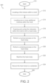
- FIG. 2 is a flow chart illustrating an exemplary method 200 for forming the coating system and securing the coating system to the substrate of the component.
- the method 200 may start at 210.
- the method 200 may include locating a first mixture within a mold.
- the first mixture may include at least one ceramic material configured to define one or more layers of the coating system, and at least one polymeric foaming composition configured to promote foaming of the first mixture during subsequent steps of the method 200.
- the ceramic material may include a rare earth silicate that may be or include at least one rare earth monosilicate (e.g., RE 2 SiO 5 , where RE is a rare earth element), at least one rare earth disilicate (e.g., RE 2 Si 2 O 7 , where RE is a rare earth element), or combinations thereof.
- a rare earth silicate that may be or include at least one rare earth monosilicate (e.g., RE 2 SiO 5 , where RE is a rare earth element), at least one rare earth disilicate (e.g., RE 2 Si 2 O 7 , where RE is a rare earth element), or combinations thereof.
- the rare earth element may include at least one of Lu (lutetium), Yb (ytterbium), Tm (thulium), Er (erbium), Ho (holmium), Dy (dysprosium), Tb (terbium), Gd (gadolinium), Eu (europium), Sm (samarium), Pm (promethium), Nd (neodymium), Pr (praseodymium), Ce (cerium), La (lanthanum), Y (yttrium), or Sc (scandium).
- the rare earth silicate is Y 2 SiO 5 , Gd 2 SiO 5 , Er 2 SiO 5 , Yb 2 SiO 5 , Lu 2 SiO 5 , Y 2 Si 2 O 7 , Gd 2 Si 2 O 7 , Er 2 Si 2 O 7 , Yb 2 Si 2 O 7 , or Lu 2 Si 2 O 7 , or combinations thereof.
- the polymeric foaming composition may include one or more polymeric materials, such as a polymer resin or polyol, configured to function as a temporary base material for the foam body,
- the polymeric material may be a thermoplastic or thermosetting polymer.
- the polymeric foaming composition may include one or more blowing agents configured to generate gas bubbles within the polymer/ceramic matrix to form the porous structure (i.e., foam body).
- the blowing agent(s) may be chemical blowing agents configured to release gases upon reaction with other components of the polymeric foaming composition (e.g., water, enolizable organic compounds, polycarboxylic acid, boric acid, etc.) or may be physical blowing agents configured to release gases by vaporizing a volatile compound from the heat generated by the exothermic polymerization reaction (e.g., cyclopentane, npentane, liquified CO 2 , methyl chloride hydrocarbons, and halogen-free azeotropes, etc.)
- the polymeric foaming composition may include one or more catalysts configured to accelerate the chemical reactions that lead to foaming.
- the catalyst(s) may promote decomposition of chemical blowing agent(s) or a reaction between polyol(s) and isocyanate(s) in the case of polyurethane foams.
- the polymeric foaming composition may include one or more crosslinking agents and/or chain extenders configured to promote stability and mechanical properties of the foam body (e.g., glycerol, ethylene glycol, diamines, etc.).
- crosslinking agents and/or chain extenders configured to promote stability and mechanical properties of the foam body (e.g., glycerol, ethylene glycol, diamines, etc.).
- the polymeric foaming composition may include one or more surfactants, also known as foam stabilizers or surface-active agents, configured to promote stabilization the gas bubbles formed during foaming and prevent coalescence (e.g., silicone-based surfactants).
- the surfactant(s) may improve the foam's cell structure and homogeneity.
- additives may be included in the first mixture to provide additional modifications to the foaming process and/or the resulting foam body.
- the polymeric foaming composition may be a polyurethane foaming composition.
- the polyurethane foaming composition may include a polyol (e.g., polyether polyol, polyester polyol, etc.), an isocyanate (e.g., methylene diphenyl diisocyanate, toluene diisocyanate, etc.), blowing agent(s) (e.g., pentane, cyclopentane, or carbon dioxide), surfactant(s), catalyst(s) (e.g., tin-based catalysts like stannous octoate), curative(s) (e.g., cross-linkers or chain extenders), and/or additive(s).
- a polyol e.g., polyether polyol, polyester polyol, etc.
- an isocyanate e.g., methylene diphenyl diisocyanate, toluene diisocyanate, etc.
- blowing agent(s)
- the polyol and isocyanate react to form a main polymer chain of the polyurethane foam.
- the blowing agent(s) are responsible for generating gas, creating the material's porous structure.
- the surfactant(s), catalyst(s), and curative(s) aid the polymer system in stabilizing and maintaining the desired rate of reaction. Additive(s) may be included to impart additional properties.
- the polymeric foaming composition may be a polyimide foaming composition.
- the polyimide foaming composition may include polyimide resin(s), blowing agent(s), surfactant(s), catalyst(s), curative(s), and/or additive(s).
- the polyimide resins form a main polymer chain of the polyimide foam.
- the blowing agent(s), surfactant(s), catalyst(s), curative(s), and additive(s) function as previously described.
- the first mixture is a flowable fluid and locating the first mixture in the mold cavity of the mold may include pouring or injecting the first mixture into the mold, for example, through a mixing head.
- the mold may be pre-heated.
- the method 200 may optionally include locating one or more additional mixtures within the mold.
- the additional mixture(s) may also include a ceramic material and a foaming composition.
- two or more mixtures may be located within the mold such that the mixtures define substantially separate fluid layers within the mold cavity. Each of the mixtures may have different compositions.
- the first and additional mixtures include the same ceramic material and different foaming compositions.
- the first and additional mixtures include different ceramic materials and different foaming compositions.
- the first and additional mixtures include different ceramic materials and the same foaming compositions.
- the foaming compositions of the first and additional mixtures include different concentrations of sintering aids, wherein lower concentrations provide less dense microstructures that promote heat resistance and higher concentrations provide more dense microstructures that promote mechanical strength.
- the method 200 may include foaming the mixture(s) to fill the mold cavity and then curing the foamed mixture(s) within the mold to form a foam body (green body) having a polymer/ceramic matrix.
- foaming the mixture(s) may include maintaining the mixture(s) within the mold cavity for a period of time sufficient to allow the components of the mixture(s) to react inside the mold causing the polymer system(s) to foam and rise.
- the foaming process includes generating gas bubbles in the mold with one or more chemical and/or physical blowing agents and thereby foaming the mixture(s).
- foaming the mixture(s) may include maintaining the mold at an elevated temperature.
- the foaming and curing processes may be performed over a period of time of 8 hours or greater, such as 12 hours or greater, such as 24 hours or greater.
- the foam body may include two or more layers of different compositions, structures, and/or properties.
- the foam body may include a first layer having pore sizes in a range of 5 to 10 micrometers and a second layer having pore sizes in a range of 20 to 50 micrometers.
- the method 200 may include performing drying and/or burn out processes.
- a heat treatment may be performed to dry the foam body.
- a heat treatment may be performed to remove non-ceramic materials from the foam body, that is, burn out/off the polymeric network and any other non-ceramic materials and thereby produce a ceramic body (brown body) having a highly porous microstructure.
- the drying process and the burn out processes are not particularly limited relative to time, temperature, or pressure and these parameters may be chosen by one of skill in the art.
- the method 200 may include performing a sintering process on the ceramic body to densify and/or crystallize the remaining ceramic material(s).
- the sintering process is not particularly limited relative to time, temperature, or pressure and these parameters may be chosen by one of skill in the art.
- the drying, burn out, and/or sintering processes may be performed in a single step.
- the mold may be located in a heating device, such as an air furnace, and heated at one or more temperatures for one or more cycles to achieve the drying, burn out, and/or sintering.
- the method 200 may include machining the ceramic body.
- the machining process is not particularly limited relative to any particular cutting or abrasion tool.
- the machining process may include modifying the ceramic body to have a shape conformal to the surface of the substrate.
- the method 200 may include providing a substrate and securing the ceramic body to a surface of the substrate to define at least one layer of the coating system thereon.
- the step of providing the substrate may include various processes of manufacturing the substrate (e.g., casting, machining, etc.) and/or preparing the substrate for securing the coating system thereto (e.g., etching, cleaning, etc.).
- the step of securing the ceramic body to the substrate may be performed by various processes.
- the ceramic body may be bonded to the surface of the substrate with a bonding or adhesive material, such as a glass, braze, etc.
- the ceramic body may be attached to the surface of the substrate by mechanical means, such as tabs/slots, tails/slots, pins, clips, etc.
- the ceramic body may define a coating system or layer thereof having a thickness of greater than 0.5 millimeter, such as greater than 0.75 millimeter, such as greater than 1 millimeter.
- the method 200 may include forming a dense outer layer on the ceramic body configured to reduce a likelihood that fluids pass into the voids of the ceramic body and, potentially, contact the surface of the underlying substrate.
- the dense outer layer may have little to no voids open at the surface thereof, and may be substantially or relatively impermeable to fluids, such as water vapor.
- the dense outer layer may have a density of 95% or greater, such as 98% or greater.
- the dense outer layer may have a thickness of 5 to 30 micrometers.
- the dense outer layer may be defined by portions of the ceramic body that contacted inner surfaces of the mold during the foaming and curing of the mixture(s). In such embodiments, the dense outer layer may be retained during the machining step (step 222).
- the dense outer layer may be formed by application of a sealing composition to the foam body or the ceramic body. In such embodiments, the sealing composition may be applied prior to or subsequent to securing the ceramic body to the substrate.
- the sealing compositions may include an oxide material configured to promote steam resistance and/or thermal stability. In some embodiments, the sealing composition may include the same or similar material as the ceramic material of the first mixture.
- the ceramic material of the first mixture may be a disilicate material and the sealing composition may include a monosilicate material.
- the dense outer layer may be formed by abrasion.
- securing the ceramic body to the substrate may include orienting the ceramic body such that the dense outer layer defines an outermost surface of the ceramic body relative to the substrate.
- the method 200 may end at 226.
- the microstructure of the TBC may be controlled by the choice of the polymeric foaming composition, the components of the polymeric foaming composition, and the concentration of such components.
- a porosity, pore size distribution, density, or other property of one or more layers of the ceramic body may be controlled by selectively adjusting components and/or concentrations of components within the polymeric foaming composition(s), such as adjusting a type or a concentration of sintering aids, catalysts, surfactants, etc.
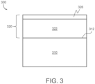
- FIGS. 3 and 4 present exemplary components 300 and 400 having coating systems 320 and 420 thereon, respectively, in accordance with various aspects described herein.
- the coating systems 320 and 420 may be formed by the method 200 and have various layer compositions as described above.
- the components 300 and 400 and the coating systems 320 and 420 thereon, respectively, are merely exemplary and the components, coating systems, and methods disclosed herein are not limited to the examples of FIGS. 3 and 4 .
- the component 300 includes a substrate 310 having the coating system 320 secured and/or bonded to a surface 312 of the substrate 310.
- the coating system 320 defines a TBC configured to provide thermal protection to the underlying substrate 310.
- the coating system 320 includes a porous layer 322 and a dense layer 326 both formed of a ceramic material, such as a rare earth disilicate.
- the porous layer 322 has a porous microstructure and the dense layer 326 has a dense microstructure with little to no porosity.
- the component 300 may be produced by the steps 212 and 216-224 of the method 200.
- the component 400 includes a substrate 410 having the coating system 420 secured and/or bonded to a surface 412 of the substrate 410.
- the coating system 420 defines a TBC configured to provide thermal protection to the underlying substrate 410.
- the coating system 420 includes a first porous layer 422, a second porous layer 424, and a dense layer 426 each formed of a ceramic material, such as a rare earth disilicate.
- the first porous layer 422 has a first microstructure
- the second porous layer 424 has a second microstructure
- the dense layer 426 has a third microstructure.
- the first microstructure and the second porous microstructure may differ in porosity, pore size distribution, or other features.
- the first microstructure includes open cell porosity and the second microstructure includes closed cell porosity.
- the third microstructure may have little to no porosity.
- the component 400 may be produced by the steps 212-224 of the method 200.
- producing the component 400 may include locating a first mixture in the mold, subsequently locating a second mixture in the mold, and then simultaneously foaming and curing the first and second mixtures.
- the first and second mixtures may include first and second polymeric foaming compositions, respectively, having different compositions, and the first microstructure may result from foaming of the first mixture and the second microstructure may result from foaming of the second mixture.
- the components, coating systems, and methods disclosed herein provide various benefits over certain existing coating systems and methods.
- certain methods for producing TBCs are expensive and may be limited in regard to the thickness of the TBC, for example, such as less than 15 mils (about 25 ⁇ m).
- the methods disclosed herein are capable of producing TBCs having various shapes and thickness (e.g., greater than 1 mm) at relatively low cost.
- the coating systems disclosed herein provide significant shock resistant, low conductivity, capable of surviving operating environments in excess of 3100 °F (about 1705 °C), and are abradable.
- the coating systems provide steam and fluid penetration resistance. Securing the ceramic body to the substrate post-sintering allows for increased sintering temperatures that would otherwise damage the substrate.
- the methods disclosed herein promote ease of controlling the resulting microstructure of the coating system layers through selection of the polymeric foaming composition.
- the term “substantially” denotes within 5% to account for manufacturing tolerances. Also, as used herein, the term “about” denotes within 5% to account for manufacturing tolerances.
Landscapes
- Chemical & Material Sciences (AREA)
- Engineering & Computer Science (AREA)
- Materials Engineering (AREA)
- Organic Chemistry (AREA)
- Ceramic Engineering (AREA)
- Mechanical Engineering (AREA)
- Chemical Kinetics & Catalysis (AREA)
- Metallurgy (AREA)
- Inorganic Chemistry (AREA)
- Structural Engineering (AREA)
- Manufacturing & Machinery (AREA)
- General Engineering & Computer Science (AREA)
- Physics & Mathematics (AREA)
- Plasma & Fusion (AREA)
- Turbine Rotor Nozzle Sealing (AREA)
Abstract
Description
- The present invention generally relates to coating systems, and more particularly relates to components and methods for coating the components to produce coating systems thereon that include highly porous microstructures.
- The aircraft industry's overall goal of increased engine temperatures necessitates the use of advanced ceramics like silicon nitride and SiC/SiC composites in engine components such as shrouds. Despite the ability of such ceramics to withstand high temperatures, these components require environmental barrier coatings (EBC) to survive water vapor in the combustion environment. In addition, the drive for even higher operating temperatures may require thermal barrier coatings (TBC) to enhance silicon-based ceramic component survivability.
- Hence, there is an ongoing desire for coating systems and methods for producing such coating systems capable of surviving increased engine temperatures. Furthermore, other desirable features and characteristics of the present invention will become apparent from the subsequent detailed description and the appended claims, taken in conjunction with the accompanying drawings and the foregoing technical field and background.
- This summary is provided to describe select concepts in a simplified form that are further described in the Detailed Description. This summary is not intended to identify key or essential features of the claimed subject matter, nor is it intended to be used as an aid in determining the scope of the claimed subject matter.
- In various embodiments, a method is provided that includes locating a first mixture within a mold cavity defined by inner surfaces of a mold, the first mixture including a ceramic material and a first polymeric foaming composition, retaining the first mixture within the mold cavity for a period of time sufficient to allow the first mixture to foam and cure and thereby produce a foam body having a shape defined by the mold cavity, performing a one or more heat treatments to remove non-ceramic materials from the foam body and sinter the ceramic material to produce a ceramic body, wherein a microstructure of the ceramic body is based on the first polymeric foaming composition, performing a machining process to modify a size and/or a shape of the ceramic body, and securing the ceramic body to a substrate of a component to define at least a portion of a thermal barrier coating (TBC) on the substrate. The component is configured to be installed in a gas turbine engine.
- In various embodiments, a component for a gas turbine engine is provided that includes a substrate and a thermal barrier coating (TBC) having at least a first layer secured to a surface of the substrate. The first layer is formed of a ceramic material with a first microstructure that includes a plurality of interconnected unit cells having struts that have a relative density of greater than 98 percent and a closed cell porosity of 10 percent or greater. The TBC is secured to the substrate subsequent to formation of the TBC.
- Furthermore, other desirable features and characteristics of the component and method will become apparent from the subsequent detailed description and the appended claims, taken in conjunction with the accompanying drawings and the preceding background.
- The present disclosure will hereinafter be described in conjunction with the following drawing figures, wherein like numerals denote like elements, and wherein:
-
FIG. 1 is a schematic view of a gas turbine engine according to example embodiments of the present disclosure; -
FIG. 2 is a flowchart illustrating certain aspects of a method for producing a coating system on a component according to example embodiments of the present disclosure; -
FIG. 3 is a cross-sectional view of a first component having a coating system thereon according to example embodiments of the present disclosure; and -
FIG. 4 is a cross-sectional view of a second component having a coating system thereon according to example embodiments of the present disclosure. - The following detailed description is merely exemplary in nature and is not intended to limit the invention or the application and uses of the invention. As used herein, the word "exemplary" means "serving as an example, instance, or illustration." Thus, any embodiment described herein as "exemplary" is not necessarily to be construed as preferred or advantageous over other embodiments. All of the embodiments described herein are exemplary embodiments provided to enable persons skilled in the art to make or use the invention and not to limit the scope of the invention which is defined by the claims. Furthermore, there is no intention to be bound by any expressed or implied theory presented in the preceding technical field, background, brief summary, or the following detailed description.
- Broadly, embodiments of the present disclosure include components that have a coating system fixed and/or bonded to a substrate thereof, and manufacturing methods for providing the components. In various embodiments, the component may be configured for use in a high temperature and/or high pressure environment, and the coating system may be a protective ceramic coating, such as an environmental barrier coating (EBC) and/or a thermal barrier coating (TBC). In various embodiments, the coating system of the components include at least one layer comprising a highly porous microstructure that includes a rare-earth silicate, such as but not limited to ytterbium monosilicate (YbMS, Yb2SiO5) and/or ytterbium disilicate (YbDS, Yb2Si2O7). The coating systems may be capable of providing environmental and/or thermal protection at high temperatures, such as 2850 °F (about 1565 °C) or greater, such as 3100 °F (about 1705 °C) or greater.
- The components are not particularly limited to any size, shape, or application. The components may be used in any industry including, but not limited to, the automobile industry, the aerospace industry, the transportation industry, the power generation industry, the mining industry, etc. The components may be particularly suitable for use in a high temperature and/or high pressure environments including, but not limited to, power plants, mining, petroleum and oil refining, fracking, under water applications, deep sea applications, etc. In various embodiments, the components may be any portion of a vehicle, aircraft, ship, train, etc. In some embodiments, the components may be any portion of an engine or a motor, such as used for propulsion of a vehicle, aircraft, ship, train, etc. In some embodiments, the components may be any portion of a gas turbine engine, such as an aircraft engine. A nonlimiting example includes a shroud for a gas turbine engine.
- Referring to
FIG. 1 , a cross-sectional view of an exemplary turbofangas turbine engine 100 is illustrated. In general, thegas turbine engine 100 includes afan section 102, acompressor section 104, acombustion section 106, aturbine section 108, and anexhaust section 110. The fan section includes afan 112 mounted on the low-pressure turbine shaft 138 and contained within afan casing 114. Thefan 112 induces air from the surrounding environment into the engine and passes a fraction of this air toward thecompressor section 104. Thecompressor section 104 includes at least one compressor and, in the depicted embodiment, includes a low-pressure compressor 120 and a high-pressure compressor 122. The low-pressure compressor 120 raises the pressure of the air directed into it from thefan 112 and directs the compressed air into the high-pressure compressor 122. The compressors are mounted onturbine shafts shroud 118. - The
combustion section 106 ofgas turbine engine 100 includes acombustor 124 in which the high-pressure air from the high-pressure compressor 122 is mixed with fuel and combusted to generate a combustion gas. The combustion gas is then directed into theturbine section 108. Theturbine section 108 includes a number of turbines disposed in axial flow series. The combustion gas from thecombustion section 106 expands first through the high-pressure turbine 126, passes through theinter-turbine duct 128, and expands again through the low-pressure turbine 130, causing the turbine rotors to rotate at different speeds. As theturbines gas turbine engine 100 via concentrically disposed shafts orspools exhaust section 110. - The
gas turbine engine 100 may include at least one component with a coated outer surface. The component may be included in an area of thegas turbine engine 100 subjected to high-temperature environments. The coated outer surface is defined by one or more layers of the coating system secured directly or indirectly (e.g., via underlying layers thereof) to surfaces of a substrate (i.e., an underlying layer or body). The substrate may be defined by a component body. The component body may define a majority of the component. The component body may have a variety of shapes without departing from the scope of the present disclosure. - In various embodiments, the component body and, thus the substrate, may be constructed of a ceramic material. The substrate may include or be a monolithic ceramic or a ceramic matrix composite. A ceramic is an inorganic solid that may include metals, non-metals, or metalloid atoms primarily held together with ionic and/or covalent bonds. Ceramics may be crystalline, semi-crystalline, partially crystalline, or amorphous. The substrate may include ceramic material throughout, such that the substrate is essentially 100 percent ceramic. Alternatively, the substrate may be defined as a substrate that includes a ceramic coating disposed over a non-ceramic (e.g., metallic) core. The substrate is not particularly limited in size, dimensions, etc.
- The substrate may be or include any ceramic known in the art. For example, the substrate may be or include silicon nitride, silicon carbide, silicon-carbide-silicon carbide composites, silicon oxynitride, SiAlON materials (materials that include silicon, aluminum, oxygen, and nitrogen), silicon dioxide, and combinations thereof. In other embodiments, the substrate may be or include silicon nitride, silicon carbide, silicon-carbide-silicon carbide composites, or combinations thereof. In various embodiments, the substrate may be or include from about 50 to about 100 weight percent, or from about 80 to about 100 weight percent, or from about 99 to about 100 weight percent of silicon nitride, silicon carbide, silicon oxynitride, SiAlON materials, silicon dioxide, and combinations thereof. In various nonlimiting embodiments, all values and ranges of values including and between those set forth above are hereby expressly contemplated for use herein.
- The coating system may include a plurality of layers. In various embodiments, the coating system includes an environmental barrier coating (EBC) having one or more layers, and a thermal barrier coating (TBC) having one or more layers. In such embodiments, the EBC may serve as a barrier between the substrate and high temperature air or steam when operating in conditions wherein water vapor becomes a reactive species and causes erosion, and the TBC may have low thermal conductivity for thermally protecting the underlying EBC and the substrate. The EBC and the TBC may each include one or more layers. The EBC may be provided on an underlying surface, such as that of a substrate or another coating thereon, and the TBC may be provided on the EBC, if present. In some embodiments, the coating system omits the EBC and only includes the TBC. The layers of the coating system are not particularly limited in size, thickness, or other dimensions. In various embodiments, one or more of the layers of the coating system may have a thickness of from about 25 µm to about 1 mm, such as 1 mm or greater.
- In various embodiments, the coating system includes a TBC having one or more layers formed of one or more ceramic materials. The TBC may be formed of or include various ceramic materials without departing from the scope of the present disclosure. In various embodiments, the TBC may include a rare earth silicate that may be or include at least one rare earth monosilicate (e.g., RE2SiO5, where RE is a rare earth element), at least one rare earth disilicate (e.g., RE2Si2O7, where RE is a rare earth element), or combinations thereof. The rare earth element may include at least one of Lu (lutetium), Yb (ytterbium), Tm (thulium), Er (erbium), Ho (holmium), Dy (dysprosium), Tb (terbium), Gd (gadolinium), Eu (europium), Sm (samarium), Pm (promethium), Nd (neodymium), Pr (praseodymium), Ce (cerium), La (lanthanum), Y (yttrium), or Sc (scandium). In various embodiments, the rare earth silicate is Y2SiO5, Gd2SiO5, Er2SiO5, Yb2SiO5, Lu2SiO5, Y2Si2O7, Gd2Si2O7, Er2Si2O7, Yb2Si2O7, or Lu2Si2O7, or combinations thereof.
- In various embodiments, the TBC may have a highly porous microstructure that includes a plurality of interconnected unit cells having cell walls or struts that have substantially 100% relative density, such as greater than 99 percent, such as greater than 98 percent. The TBC may have a closed-cell structure, an open-cell structure, or a combination thereof. In the closed-cell structure, the TBC primarily includes a plurality of discrete voids, each surrounded by a solid material (e.g., the ceramic material), whereas in the open-cell structure, the TBC primarily includes a plurality of interconnected voids. The TBC may have various porosities (i.e., percentage of voids), pore sizes, and pore size distributions. In various embodiments, one or more layers of the TBC may have a closed cell porosity of about 10 to 40 percent. In various embodiments, one or more layers of the TBC may have an open-cell porosity of 60 to 95 percent. In some embodiments, the TBC may have pore sizes in a range of 5 to 50 micrometers (µm). In some embodiments, the TBC has a minimum pore size of about 5 µm, 10 µm, 15 µm, 20 µm, 25 µm, 30 µm, 35 µm, 40 µm, or 45 µm. In some embodiments, the TBC has a maximum pore size of about 50 µm, 45 µm, 40 µm, 35 µm, 30 µm, 25 µm, 20 µm, 15 µm, or 10 µm. In various embodiments, the TBC may have a porosity gradient through a thickness thereof. In some embodiments, the porosity gradient includes increasing porosity with increasing distance from the substrate.
- The coating system may be formed and secured to the surface of the substrate by various processes. For examples,
FIG. 2 is a flow chart illustrating anexemplary method 200 for forming the coating system and securing the coating system to the substrate of the component. Themethod 200 may start at 210. - At 212, the
method 200 may include locating a first mixture within a mold. The first mixture may include at least one ceramic material configured to define one or more layers of the coating system, and at least one polymeric foaming composition configured to promote foaming of the first mixture during subsequent steps of themethod 200. - In various embodiments, the ceramic material may include a rare earth silicate that may be or include at least one rare earth monosilicate (e.g., RE2SiO5, where RE is a rare earth element), at least one rare earth disilicate (e.g., RE2Si2O7, where RE is a rare earth element), or combinations thereof. The rare earth element may include at least one of Lu (lutetium), Yb (ytterbium), Tm (thulium), Er (erbium), Ho (holmium), Dy (dysprosium), Tb (terbium), Gd (gadolinium), Eu (europium), Sm (samarium), Pm (promethium), Nd (neodymium), Pr (praseodymium), Ce (cerium), La (lanthanum), Y (yttrium), or Sc (scandium). In various embodiments, the rare earth silicate is Y2SiO5, Gd2SiO5, Er2SiO5, Yb2SiO5, Lu2SiO5, Y2Si2O7, Gd2Si2O7, Er2Si2O7, Yb2Si2O7, or Lu2Si2O7, or combinations thereof.
- In various embodiments, the polymeric foaming composition may include one or more polymeric materials, such as a polymer resin or polyol, configured to function as a temporary base material for the foam body, In various embodiments, the polymeric material may be a thermoplastic or thermosetting polymer.
- In various embodiments, the polymeric foaming composition may include one or more blowing agents configured to generate gas bubbles within the polymer/ceramic matrix to form the porous structure (i.e., foam body). In various embodiments, the blowing agent(s) may be chemical blowing agents configured to release gases upon reaction with other components of the polymeric foaming composition (e.g., water, enolizable organic compounds, polycarboxylic acid, boric acid, etc.) or may be physical blowing agents configured to release gases by vaporizing a volatile compound from the heat generated by the exothermic polymerization reaction (e.g., cyclopentane, npentane, liquified CO2, methyl chloride hydrocarbons, and halogen-free azeotropes, etc.)
- In various embodiments, the polymeric foaming composition may include one or more catalysts configured to accelerate the chemical reactions that lead to foaming. For example, the catalyst(s) may promote decomposition of chemical blowing agent(s) or a reaction between polyol(s) and isocyanate(s) in the case of polyurethane foams.
- In various embodiments, the polymeric foaming composition may include one or more crosslinking agents and/or chain extenders configured to promote stability and mechanical properties of the foam body (e.g., glycerol, ethylene glycol, diamines, etc.).
- In various embodiments, the polymeric foaming composition may include one or more surfactants, also known as foam stabilizers or surface-active agents, configured to promote stabilization the gas bubbles formed during foaming and prevent coalescence (e.g., silicone-based surfactants). The surfactant(s) may improve the foam's cell structure and homogeneity.
- Other additives may be included in the first mixture to provide additional modifications to the foaming process and/or the resulting foam body.
- In various exemplary embodiments, the polymeric foaming composition may be a polyurethane foaming composition. In such embodiments, the polyurethane foaming composition may include a polyol (e.g., polyether polyol, polyester polyol, etc.), an isocyanate (e.g., methylene diphenyl diisocyanate, toluene diisocyanate, etc.), blowing agent(s) (e.g., pentane, cyclopentane, or carbon dioxide), surfactant(s), catalyst(s) (e.g., tin-based catalysts like stannous octoate), curative(s) (e.g., cross-linkers or chain extenders), and/or additive(s). The polyol and isocyanate react to form a main polymer chain of the polyurethane foam. The blowing agent(s) are responsible for generating gas, creating the material's porous structure. The surfactant(s), catalyst(s), and curative(s) aid the polymer system in stabilizing and maintaining the desired rate of reaction. Additive(s) may be included to impart additional properties.
- In various exemplary embodiments, the polymeric foaming composition may be a polyimide foaming composition. In such embodiments, the polyimide foaming composition may include polyimide resin(s), blowing agent(s), surfactant(s), catalyst(s), curative(s), and/or additive(s). The polyimide resins form a main polymer chain of the polyimide foam. The blowing agent(s), surfactant(s), catalyst(s), curative(s), and additive(s) function as previously described.
- Various methods may be used to combine the various components of the first mixture. Such methods may depend on the specific polymer system and/or components of the first mixture. Therefore, the method used may be chosen by one of skill in the art.
- In various embodiments, the first mixture is a flowable fluid and locating the first mixture in the mold cavity of the mold may include pouring or injecting the first mixture into the mold, for example, through a mixing head. In various embodiments, the mold may be pre-heated.
- At 214, the
method 200 may optionally include locating one or more additional mixtures within the mold. The additional mixture(s) may also include a ceramic material and a foaming composition. In various embodiments, two or more mixtures may be located within the mold such that the mixtures define substantially separate fluid layers within the mold cavity. Each of the mixtures may have different compositions. In various embodiments, the first and additional mixtures include the same ceramic material and different foaming compositions. In various embodiments, the first and additional mixtures include different ceramic materials and different foaming compositions. In various embodiments, the first and additional mixtures include different ceramic materials and the same foaming compositions. In various embodiments, the foaming compositions of the first and additional mixtures include different concentrations of sintering aids, wherein lower concentrations provide less dense microstructures that promote heat resistance and higher concentrations provide more dense microstructures that promote mechanical strength. - In various embodiments, the first mixture and/or the additional mixture(s) may include 20 to 40 percent by volume (vol.%) of the ceramic material and 60 to 80 vol.% of the polymeric foaming composition. In various embodiments, the first mixture and/or the additional mixture(s) may include 25 to 35 vol.% of the ceramic material and 65 to 75 vol.% of the polymeric foaming composition. All volume measurements are prior to foaming. As a nonlimiting example, the first mixture may include about 3.5 grams of YBDS for every 1.5 milliliters of the polymeric foaming composition.
- At 216, the
method 200 may include foaming the mixture(s) to fill the mold cavity and then curing the foamed mixture(s) within the mold to form a foam body (green body) having a polymer/ceramic matrix. In various embodiments, foaming the mixture(s) may include maintaining the mixture(s) within the mold cavity for a period of time sufficient to allow the components of the mixture(s) to react inside the mold causing the polymer system(s) to foam and rise. In various embodiments, the foaming process includes generating gas bubbles in the mold with one or more chemical and/or physical blowing agents and thereby foaming the mixture(s). In various embodiments, foaming the mixture(s) may include maintaining the mold at an elevated temperature. In various embodiments, the foaming and curing processes may be performed over a period of time of 8 hours or greater, such as 12 hours or greater, such as 24 hours or greater. - During the curing process, polymer chains within the polymer system react and cross-link to convert the flowable fluid mixture(s) to a solid tridimensional polymeric network. The curing process may occur with or without curing agents. In some embodiments, curing may be promoted or induced by application of heat, radiation, or electron beams. In embodiments that include locating more than one mixture within the mold (e.g., step 214), the foam body may include two or more layers of different compositions, structures, and/or properties. For example, the foam body may include a first layer having pore sizes in a range of 5 to 10 micrometers and a second layer having pore sizes in a range of 20 to 50 micrometers.
- At 218, the
method 200 may include performing drying and/or burn out processes. In some embodiments, a heat treatment may be performed to dry the foam body. In some embodiments, a heat treatment may be performed to remove non-ceramic materials from the foam body, that is, burn out/off the polymeric network and any other non-ceramic materials and thereby produce a ceramic body (brown body) having a highly porous microstructure. The drying process and the burn out processes are not particularly limited relative to time, temperature, or pressure and these parameters may be chosen by one of skill in the art. - At 220, the
method 200 may include performing a sintering process on the ceramic body to densify and/or crystallize the remaining ceramic material(s). The sintering process is not particularly limited relative to time, temperature, or pressure and these parameters may be chosen by one of skill in the art. In various embodiments, the drying, burn out, and/or sintering processes may be performed in a single step. For example, the mold may be located in a heating device, such as an air furnace, and heated at one or more temperatures for one or more cycles to achieve the drying, burn out, and/or sintering. - At 222, the
method 200 may include machining the ceramic body. The machining process is not particularly limited relative to any particular cutting or abrasion tool. In various embodiments, the machining process may include modifying the ceramic body to have a shape conformal to the surface of the substrate. - At 224, the
method 200 may include providing a substrate and securing the ceramic body to a surface of the substrate to define at least one layer of the coating system thereon. The step of providing the substrate may include various processes of manufacturing the substrate (e.g., casting, machining, etc.) and/or preparing the substrate for securing the coating system thereto (e.g., etching, cleaning, etc.). The step of securing the ceramic body to the substrate may be performed by various processes. In various embodiments, the ceramic body may be bonded to the surface of the substrate with a bonding or adhesive material, such as a glass, braze, etc. In various embodiments, the ceramic body may be attached to the surface of the substrate by mechanical means, such as tabs/slots, tails/slots, pins, clips, etc. In various embodiments, the ceramic body may define a coating system or layer thereof having a thickness of greater than 0.5 millimeter, such as greater than 0.75 millimeter, such as greater than 1 millimeter. - In various embodiments, the
method 200 may include forming a dense outer layer on the ceramic body configured to reduce a likelihood that fluids pass into the voids of the ceramic body and, potentially, contact the surface of the underlying substrate. In various embodiments, the dense outer layer may have little to no voids open at the surface thereof, and may be substantially or relatively impermeable to fluids, such as water vapor. In various embodiments, the dense outer layer may have a density of 95% or greater, such as 98% or greater. In various embodiments, the dense outer layer may have a thickness of 5 to 30 micrometers. - Various methods may be used to form the dense layer. In various embodiments, the dense outer layer may be defined by portions of the ceramic body that contacted inner surfaces of the mold during the foaming and curing of the mixture(s). In such embodiments, the dense outer layer may be retained during the machining step (step 222). In various embodiments, the dense outer layer may be formed by application of a sealing composition to the foam body or the ceramic body. In such embodiments, the sealing composition may be applied prior to or subsequent to securing the ceramic body to the substrate. Various sealing compositions may be used. In some embodiments, the sealing compositions may include an oxide material configured to promote steam resistance and/or thermal stability. In some embodiments, the sealing composition may include the same or similar material as the ceramic material of the first mixture. In one nonlimiting example, the ceramic material of the first mixture may be a disilicate material and the sealing composition may include a monosilicate material. In various embodiments, the dense outer layer may be formed by abrasion. In various embodiments, securing the ceramic body to the substrate may include orienting the ceramic body such that the dense outer layer defines an outermost surface of the ceramic body relative to the substrate.
- The
method 200 may end at 226. - In various embodiments, the microstructure of the TBC may be controlled by the choice of the polymeric foaming composition, the components of the polymeric foaming composition, and the concentration of such components. For example, a porosity, pore size distribution, density, or other property of one or more layers of the ceramic body may be controlled by selectively adjusting components and/or concentrations of components within the polymeric foaming composition(s), such as adjusting a type or a concentration of sintering aids, catalysts, surfactants, etc.
-
FIGS. 3 and4 presentexemplary components coating systems coating systems method 200 and have various layer compositions as described above. Thecomponents coating systems FIGS. 3 and4 . - Referring now to
FIG. 3 , a cross-sectional view of a portion of theexemplary component 300 is presented. Thecomponent 300 includes asubstrate 310 having thecoating system 320 secured and/or bonded to asurface 312 of thesubstrate 310. In this example, thecoating system 320 defines a TBC configured to provide thermal protection to theunderlying substrate 310. Thecoating system 320 includes aporous layer 322 and adense layer 326 both formed of a ceramic material, such as a rare earth disilicate. Theporous layer 322 has a porous microstructure and thedense layer 326 has a dense microstructure with little to no porosity. Thecomponent 300 may be produced by thesteps 212 and 216-224 of themethod 200. - Referring now to
FIG. 4 , a cross-sectional view of a portion of theexemplary component 400 is presented. Thecomponent 400 includes asubstrate 410 having thecoating system 420 secured and/or bonded to asurface 412 of thesubstrate 410. In this example, thecoating system 420 defines a TBC configured to provide thermal protection to theunderlying substrate 410. Thecoating system 420 includes a firstporous layer 422, a secondporous layer 424, and adense layer 426 each formed of a ceramic material, such as a rare earth disilicate. The firstporous layer 422 has a first microstructure, the secondporous layer 424 has a second microstructure, and thedense layer 426 has a third microstructure. The first microstructure and the second porous microstructure may differ in porosity, pore size distribution, or other features. In one example, the first microstructure includes open cell porosity and the second microstructure includes closed cell porosity. The third microstructure may have little to no porosity. Thecomponent 400 may be produced by the steps 212-224 of themethod 200. - In various embodiments, producing the
component 400 may include locating a first mixture in the mold, subsequently locating a second mixture in the mold, and then simultaneously foaming and curing the first and second mixtures. In such embodiments, the first and second mixtures may include first and second polymeric foaming compositions, respectively, having different compositions, and the first microstructure may result from foaming of the first mixture and the second microstructure may result from foaming of the second mixture. - The components, coating systems, and methods disclosed herein provide various benefits over certain existing coating systems and methods. For example, certain methods for producing TBCs are expensive and may be limited in regard to the thickness of the TBC, for example, such as less than 15 mils (about 25 µm). In contrast, the methods disclosed herein are capable of producing TBCs having various shapes and thickness (e.g., greater than 1 mm) at relatively low cost. In addition, the coating systems disclosed herein provide significant shock resistant, low conductivity, capable of surviving operating environments in excess of 3100 °F (about 1705 °C), and are abradable. In embodiments that include a dense outer layer, the coating systems provide steam and fluid penetration resistance. Securing the ceramic body to the substrate post-sintering allows for increased sintering temperatures that would otherwise damage the substrate. The methods disclosed herein promote ease of controlling the resulting microstructure of the coating system layers through selection of the polymeric foaming composition.
- In this document, relational terms such as first and second, and the like may be used solely to distinguish one entity or action from another entity or action without necessarily requiring or implying any actual such relationship or order between such entities or actions. Numerical ordinals such as "first," "second," "third," etc. simply denote different singles of a plurality and do not imply any order or sequence unless specifically defined by the claim language. The sequence of the text in any of the claims does not imply that process steps must be performed in a temporal or logical order according to such sequence unless it is specifically defined by the language of the claim. The process steps may be interchanged in any order without departing from the scope of the invention as long as such an interchange does not contradict the claim language and is not logically nonsensical.
- As used herein, the term "substantially" denotes within 5% to account for manufacturing tolerances. Also, as used herein, the term "about" denotes within 5% to account for manufacturing tolerances.
- While at least one exemplary embodiment has been presented in the foregoing detailed description of the invention, it should be appreciated that a vast number of variations exist. It should also be appreciated that the exemplary embodiment or exemplary embodiments are only examples, and are not intended to limit the scope, applicability, or configuration of the invention in any way. Rather, the foregoing detailed description will provide those skilled in the art with a convenient road map for implementing an exemplary embodiment of the invention. It being understood that various changes may be made in the function and arrangement of elements described in an exemplary embodiment without departing from the scope of the invention as set forth in the appended claims.
Claims (15)
- A method, comprising:locating a first mixture within a mold cavity defined by inner surfaces of a mold, the first mixture including a ceramic material and a first polymeric foaming composition;retaining the first mixture within the mold cavity for a period of time sufficient to allow the first mixture to foam and cure and thereby produce a foam body having a shape defined by the mold cavity;performing a one or more heat treatments to remove non-ceramic materials from the foam body and sinter the ceramic material to produce a ceramic body, wherein a microstructure of the ceramic body is based on the first polymeric foaming composition;performing a machining process to modify a size and/or a shape of the ceramic body; andsecuring the ceramic body to a substrate of a component to define at least a portion of a thermal barrier coating (TBC) on the substrate, wherein the component is configured to be installed in a gas turbine engine.
- The method of claim 1, further comprising locating a second mixture in the mold cavity, wherein the first mixture and the second mixture simultaneously foam and cure within the mold cavity, wherein the second mixture includes the ceramic material and a second polymeric foaming composition, wherein the ceramic body includes a first layer having a first microstructure resulting from foaming of the first mixture and a second layer having a second microstructure resulting from foaming of the second mixture.
- The method of claim 2, wherein the first microstructure and the second microstructure have different ranges of pore sizes.
- The method of claim 2, wherein the first microstructure includes closed cell porosity, and the second microstructure includes open cell porosity.
- The method of claim 1, wherein the foam body includes a dense outer layer formed by contact with the inner surfaces of the mold during foaming and curing of the first mixture, wherein securing the ceramic body to the substrate includes orienting the ceramic body such that the dense outer layer defines an outermost surface of the TBC relative to the substrate.
- The method of claim 1, wherein the foam body includes a dense outer layer formed by application of a sealing composition to the ceramic body, wherein securing the ceramic body to the substrate includes orienting the ceramic body such that the dense outer layer defines an outermost surface of the TBC relative to the substrate.
- The method of claim 1, wherein the ceramic material is a rare earth disilicate and the first polymeric foaming composition is a polyurethane foaming composition.
- The method of claim 1, wherein securing the ceramic body to the substrate includes performing a bonding process with an adhesive material.
- The method of claim 1, wherein the microstructure of the ceramic body is controlled by selection of components and concentrations of such components in the first polymeric foaming composition.
- A component for a gas turbine engine, comprising:a substrate;a thermal barrier coating (TBC) having at least a first layer secured to a surface of the substrate, the first layer formed of a ceramic material with a first microstructure that includes a plurality of interconnected unit cells having struts that have a relative density of greater than 98 percent and a closed cell porosity of 10 percent or greater,wherein the TBC is secured to the substrate subsequent to formation of the TBC.
- The component of claim 10, wherein the TBC includes at least a second layer integral with the first layer, the second layer formed of the ceramic material with a second microstructure having a range of pore sizes that is different from a range of pore sizes of the first microstructure.
- The component of claim 10, wherein the TBC includes at least a second layer integral with the first layer, the second layer formed of the ceramic material with a second microstructure, wherein the second microstructure includes open cell porosity.
- The component of claim 10, wherein the TBC includes a dense layer that defines an outermost surface of the TBC relative to the substrate.
- The component of claim 10, wherein the TBC is secured to the surface of the substrate with a bonding or adhesive material.
- The component of claim 10, wherein the first layer has a thickness of 0.5 millimeters or greater.
Applications Claiming Priority (1)
| Application Number | Priority Date | Filing Date | Title |
|---|---|---|---|
| US18/461,099 US20250075303A1 (en) | 2023-09-05 | 2023-09-05 | Components having coating systems comprising highly porous layers and methods for forming the coating systems |
Publications (1)
| Publication Number | Publication Date |
|---|---|
| EP4520525A1 true EP4520525A1 (en) | 2025-03-12 |
Family
ID=92302601
Family Applications (1)
| Application Number | Title | Priority Date | Filing Date |
|---|---|---|---|
| EP24194143.4A Pending EP4520525A1 (en) | 2023-09-05 | 2024-08-12 | Components having coating systems comprising highly porous layers and methods for forming the coating systems |
Country Status (2)
| Country | Link |
|---|---|
| US (1) | US20250075303A1 (en) |
| EP (1) | EP4520525A1 (en) |
Families Citing this family (1)
| Publication number | Priority date | Publication date | Assignee | Title |
|---|---|---|---|---|
| DE102021117652B3 (en) * | 2021-07-08 | 2022-03-10 | Jenoptik Optical Systems Gmbh | Process for the integral connection of a glass element with a carrier element and optical device |
Citations (2)
| Publication number | Priority date | Publication date | Assignee | Title |
|---|---|---|---|---|
| EP3080336B1 (en) * | 2013-12-12 | 2019-11-20 | General Electric Company | Method of depositing abradable coatings under polymer gels |
| US20210188723A1 (en) * | 2019-12-20 | 2021-06-24 | Rolls-Royce Corporation | Tape casting coating for ceramic matrix composite |
Family Cites Families (3)
| Publication number | Priority date | Publication date | Assignee | Title |
|---|---|---|---|---|
| DE19621638C2 (en) * | 1996-05-30 | 2002-06-27 | Fraunhofer Ges Forschung | Open cell foam ceramic with high strength and process for its production |
| US6733907B2 (en) * | 1998-03-27 | 2004-05-11 | Siemens Westinghouse Power Corporation | Hybrid ceramic material composed of insulating and structural ceramic layers |
| EP2789804A1 (en) * | 2013-04-11 | 2014-10-15 | Alstom Technology Ltd | Gas turbine thermal shroud with improved durability |
-
2023
- 2023-09-05 US US18/461,099 patent/US20250075303A1/en active Pending
-
2024
- 2024-08-12 EP EP24194143.4A patent/EP4520525A1/en active Pending
Patent Citations (2)
| Publication number | Priority date | Publication date | Assignee | Title |
|---|---|---|---|---|
| EP3080336B1 (en) * | 2013-12-12 | 2019-11-20 | General Electric Company | Method of depositing abradable coatings under polymer gels |
| US20210188723A1 (en) * | 2019-12-20 | 2021-06-24 | Rolls-Royce Corporation | Tape casting coating for ceramic matrix composite |
Non-Patent Citations (1)
| Title |
|---|
| TANG XINYUE ET AL: "Design and formulation of polyurethane foam used for porous alumina ceramics", JOURNAL OF POLYMER RESEARCH, SPRINGER NETHERLANDS, DORDRECHT, vol. 25, no. 6, 8 May 2018 (2018-05-08), pages 1 - 10, XP036497654, ISSN: 1022-9760, [retrieved on 20180508], DOI: 10.1007/S10965-018-1535-1 * |
Also Published As
| Publication number | Publication date |
|---|---|
| US20250075303A1 (en) | 2025-03-06 |
Similar Documents
| Publication | Publication Date | Title |
|---|---|---|
| RU2435673C2 (en) | Coating for component for protection from environmental effects and method of producing said coating | |
| US11131026B2 (en) | Sintered-bonded high temperature coatings for ceramic turbomachine components | |
| CA2905252C (en) | Recession resistant ceramic matrix composites and environmental barrier coatings | |
| RU2752182C2 (en) | Part comprising a substrate and a protective barrier | |
| US20160160664A1 (en) | Recession resistant ceramic matrix composites and environmental barrier coatings | |
| EP4166525A1 (en) | Slurry-based methods for forming a bond coat and articles formed by the methods | |
| RU2762611C2 (en) | Coated part for gas turbine engine and its manufacturing method | |
| US20160153288A1 (en) | Recession resistant ceramic matrix composites and environmental barrier coatings | |
| US20200308066A1 (en) | Ceramic Matrix Composite Articles and Methods for Manufacturing the Same | |
| US20250075303A1 (en) | Components having coating systems comprising highly porous layers and methods for forming the coating systems | |
| EP3450414B1 (en) | Compositions for erosion and molten dust resistant environmental barrier coatings | |
| EP1432571A2 (en) | Hybrid ceramic material composed of insulating and structural ceramic layers | |
| EP4140972A1 (en) | Multilayer protective coating systems for gas turbine engine applications and methods for fabricating the same | |
| US11639315B2 (en) | Bond coatings having a molten silicon-phase contained between refractory layers | |
| EP4253350A1 (en) | Direct bonded environmental barrier coatings for sic/sic composites and methods for preparing the same | |
| CN109469516B (en) | Coated and turbine components, and methods of forming the same | |
| US12421175B2 (en) | Environmental barrier coatings | |
| US12228051B1 (en) | Components having coating systems comprising mud cracks and methods for forming the coating systems | |
| US20240254060A1 (en) | Bondcoats having a metalloid-based material matrix | |
| US12195405B2 (en) | Repair of a silicon-based bondcoat | |
| US20240208876A1 (en) | Components having sintering aid-free coating systems thereon and methods for producing the same | |
| CN122059723A (en) | Method of processing ceramic matrix composite CMC components |
Legal Events
| Date | Code | Title | Description |
|---|---|---|---|
| PUAI | Public reference made under article 153(3) epc to a published international application that has entered the european phase |
Free format text: ORIGINAL CODE: 0009012 |
|
| STAA | Information on the status of an ep patent application or granted ep patent |
Free format text: STATUS: THE APPLICATION HAS BEEN PUBLISHED |
|
| AK | Designated contracting states |
Kind code of ref document: A1 Designated state(s): AL AT BE BG CH CY CZ DE DK EE ES FI FR GB GR HR HU IE IS IT LI LT LU LV MC ME MK MT NL NO PL PT RO RS SE SI SK SM TR |
|
| P01 | Opt-out of the competence of the unified patent court (upc) registered |
Free format text: CASE NUMBER: APP_31464/2025 Effective date: 20250630 |
|
| STAA | Information on the status of an ep patent application or granted ep patent |
Free format text: STATUS: REQUEST FOR EXAMINATION WAS MADE |
|
| 17P | Request for examination filed |
Effective date: 20250827 |