EP4520511A1 - Induction welding of composite structures - Google Patents
Induction welding of composite structures Download PDFInfo
- Publication number
- EP4520511A1 EP4520511A1 EP24182564.5A EP24182564A EP4520511A1 EP 4520511 A1 EP4520511 A1 EP 4520511A1 EP 24182564 A EP24182564 A EP 24182564A EP 4520511 A1 EP4520511 A1 EP 4520511A1
- Authority
- EP
- European Patent Office
- Prior art keywords
- doped
- composite part
- fibers
- composite
- prepreg ply
- Prior art date
- Legal status (The legal status is an assumption and is not a legal conclusion. Google has not performed a legal analysis and makes no representation as to the accuracy of the status listed.)
- Pending
Links
Images



Classifications
-
- B—PERFORMING OPERATIONS; TRANSPORTING
- B29—WORKING OF PLASTICS; WORKING OF SUBSTANCES IN A PLASTIC STATE IN GENERAL
- B29C—SHAPING OR JOINING OF PLASTICS; SHAPING OF MATERIAL IN A PLASTIC STATE, NOT OTHERWISE PROVIDED FOR; AFTER-TREATMENT OF THE SHAPED PRODUCTS, e.g. REPAIRING
- B29C66/00—General aspects of processes or apparatus for joining preformed parts
- B29C66/01—General aspects dealing with the joint area or with the area to be joined
- B29C66/05—Particular design of joint configurations
- B29C66/10—Particular design of joint configurations particular design of the joint cross-sections
- B29C66/11—Joint cross-sections comprising a single joint-segment, i.e. one of the parts to be joined comprising a single joint-segment in the joint cross-section
- B29C66/112—Single lapped joints
- B29C66/1122—Single lap to lap joints, i.e. overlap joints
-
- B—PERFORMING OPERATIONS; TRANSPORTING
- B29—WORKING OF PLASTICS; WORKING OF SUBSTANCES IN A PLASTIC STATE IN GENERAL
- B29C—SHAPING OR JOINING OF PLASTICS; SHAPING OF MATERIAL IN A PLASTIC STATE, NOT OTHERWISE PROVIDED FOR; AFTER-TREATMENT OF THE SHAPED PRODUCTS, e.g. REPAIRING
- B29C65/00—Joining or sealing of preformed parts, e.g. welding of plastics materials; Apparatus therefor
- B29C65/02—Joining or sealing of preformed parts, e.g. welding of plastics materials; Apparatus therefor by heating, with or without pressure
- B29C65/34—Joining or sealing of preformed parts, e.g. welding of plastics materials; Apparatus therefor by heating, with or without pressure using heated elements which remain in the joint, e.g. "verlorenes Schweisselement"
- B29C65/36—Joining or sealing of preformed parts, e.g. welding of plastics materials; Apparatus therefor by heating, with or without pressure using heated elements which remain in the joint, e.g. "verlorenes Schweisselement" heated by induction
-
- B—PERFORMING OPERATIONS; TRANSPORTING
- B29—WORKING OF PLASTICS; WORKING OF SUBSTANCES IN A PLASTIC STATE IN GENERAL
- B29C—SHAPING OR JOINING OF PLASTICS; SHAPING OF MATERIAL IN A PLASTIC STATE, NOT OTHERWISE PROVIDED FOR; AFTER-TREATMENT OF THE SHAPED PRODUCTS, e.g. REPAIRING
- B29C66/00—General aspects of processes or apparatus for joining preformed parts
- B29C66/70—General aspects of processes or apparatus for joining preformed parts characterised by the composition, physical properties or the structure of the material of the parts to be joined; Joining with non-plastics material
- B29C66/72—General aspects of processes or apparatus for joining preformed parts characterised by the composition, physical properties or the structure of the material of the parts to be joined; Joining with non-plastics material characterised by the structure of the material of the parts to be joined
- B29C66/729—Textile or other fibrous material made from plastics
- B29C66/7292—Textile or other fibrous material made from plastics coated
-
- B—PERFORMING OPERATIONS; TRANSPORTING
- B29—WORKING OF PLASTICS; WORKING OF SUBSTANCES IN A PLASTIC STATE IN GENERAL
- B29C—SHAPING OR JOINING OF PLASTICS; SHAPING OF MATERIAL IN A PLASTIC STATE, NOT OTHERWISE PROVIDED FOR; AFTER-TREATMENT OF THE SHAPED PRODUCTS, e.g. REPAIRING
- B29C65/00—Joining or sealing of preformed parts, e.g. welding of plastics materials; Apparatus therefor
- B29C65/02—Joining or sealing of preformed parts, e.g. welding of plastics materials; Apparatus therefor by heating, with or without pressure
- B29C65/34—Joining or sealing of preformed parts, e.g. welding of plastics materials; Apparatus therefor by heating, with or without pressure using heated elements which remain in the joint, e.g. "verlorenes Schweisselement"
- B29C65/36—Joining or sealing of preformed parts, e.g. welding of plastics materials; Apparatus therefor by heating, with or without pressure using heated elements which remain in the joint, e.g. "verlorenes Schweisselement" heated by induction
- B29C65/3604—Joining or sealing of preformed parts, e.g. welding of plastics materials; Apparatus therefor by heating, with or without pressure using heated elements which remain in the joint, e.g. "verlorenes Schweisselement" heated by induction characterised by the type of elements heated by induction which remain in the joint
- B29C65/3636—Joining or sealing of preformed parts, e.g. welding of plastics materials; Apparatus therefor by heating, with or without pressure using heated elements which remain in the joint, e.g. "verlorenes Schweisselement" heated by induction characterised by the type of elements heated by induction which remain in the joint comprising independent continuous fibre-reinforcements
-
- B—PERFORMING OPERATIONS; TRANSPORTING
- B29—WORKING OF PLASTICS; WORKING OF SUBSTANCES IN A PLASTIC STATE IN GENERAL
- B29C—SHAPING OR JOINING OF PLASTICS; SHAPING OF MATERIAL IN A PLASTIC STATE, NOT OTHERWISE PROVIDED FOR; AFTER-TREATMENT OF THE SHAPED PRODUCTS, e.g. REPAIRING
- B29C65/00—Joining or sealing of preformed parts, e.g. welding of plastics materials; Apparatus therefor
- B29C65/02—Joining or sealing of preformed parts, e.g. welding of plastics materials; Apparatus therefor by heating, with or without pressure
- B29C65/34—Joining or sealing of preformed parts, e.g. welding of plastics materials; Apparatus therefor by heating, with or without pressure using heated elements which remain in the joint, e.g. "verlorenes Schweisselement"
- B29C65/36—Joining or sealing of preformed parts, e.g. welding of plastics materials; Apparatus therefor by heating, with or without pressure using heated elements which remain in the joint, e.g. "verlorenes Schweisselement" heated by induction
- B29C65/3604—Joining or sealing of preformed parts, e.g. welding of plastics materials; Apparatus therefor by heating, with or without pressure using heated elements which remain in the joint, e.g. "verlorenes Schweisselement" heated by induction characterised by the type of elements heated by induction which remain in the joint
- B29C65/364—Joining or sealing of preformed parts, e.g. welding of plastics materials; Apparatus therefor by heating, with or without pressure using heated elements which remain in the joint, e.g. "verlorenes Schweisselement" heated by induction characterised by the type of elements heated by induction which remain in the joint being a woven or non-woven fabric or being a mesh
-
- B—PERFORMING OPERATIONS; TRANSPORTING
- B29—WORKING OF PLASTICS; WORKING OF SUBSTANCES IN A PLASTIC STATE IN GENERAL
- B29C—SHAPING OR JOINING OF PLASTICS; SHAPING OF MATERIAL IN A PLASTIC STATE, NOT OTHERWISE PROVIDED FOR; AFTER-TREATMENT OF THE SHAPED PRODUCTS, e.g. REPAIRING
- B29C65/00—Joining or sealing of preformed parts, e.g. welding of plastics materials; Apparatus therefor
- B29C65/02—Joining or sealing of preformed parts, e.g. welding of plastics materials; Apparatus therefor by heating, with or without pressure
- B29C65/34—Joining or sealing of preformed parts, e.g. welding of plastics materials; Apparatus therefor by heating, with or without pressure using heated elements which remain in the joint, e.g. "verlorenes Schweisselement"
- B29C65/36—Joining or sealing of preformed parts, e.g. welding of plastics materials; Apparatus therefor by heating, with or without pressure using heated elements which remain in the joint, e.g. "verlorenes Schweisselement" heated by induction
- B29C65/3604—Joining or sealing of preformed parts, e.g. welding of plastics materials; Apparatus therefor by heating, with or without pressure using heated elements which remain in the joint, e.g. "verlorenes Schweisselement" heated by induction characterised by the type of elements heated by induction which remain in the joint
- B29C65/366—Joining or sealing of preformed parts, e.g. welding of plastics materials; Apparatus therefor by heating, with or without pressure using heated elements which remain in the joint, e.g. "verlorenes Schweisselement" heated by induction characterised by the type of elements heated by induction which remain in the joint being a coating or being printed, e.g. being applied as a paint or forming a printed circuit
-
- B—PERFORMING OPERATIONS; TRANSPORTING
- B29—WORKING OF PLASTICS; WORKING OF SUBSTANCES IN A PLASTIC STATE IN GENERAL
- B29C—SHAPING OR JOINING OF PLASTICS; SHAPING OF MATERIAL IN A PLASTIC STATE, NOT OTHERWISE PROVIDED FOR; AFTER-TREATMENT OF THE SHAPED PRODUCTS, e.g. REPAIRING
- B29C65/00—Joining or sealing of preformed parts, e.g. welding of plastics materials; Apparatus therefor
- B29C65/02—Joining or sealing of preformed parts, e.g. welding of plastics materials; Apparatus therefor by heating, with or without pressure
- B29C65/34—Joining or sealing of preformed parts, e.g. welding of plastics materials; Apparatus therefor by heating, with or without pressure using heated elements which remain in the joint, e.g. "verlorenes Schweisselement"
- B29C65/36—Joining or sealing of preformed parts, e.g. welding of plastics materials; Apparatus therefor by heating, with or without pressure using heated elements which remain in the joint, e.g. "verlorenes Schweisselement" heated by induction
- B29C65/3672—Joining or sealing of preformed parts, e.g. welding of plastics materials; Apparatus therefor by heating, with or without pressure using heated elements which remain in the joint, e.g. "verlorenes Schweisselement" heated by induction characterised by the composition of the elements heated by induction which remain in the joint
- B29C65/3684—Joining or sealing of preformed parts, e.g. welding of plastics materials; Apparatus therefor by heating, with or without pressure using heated elements which remain in the joint, e.g. "verlorenes Schweisselement" heated by induction characterised by the composition of the elements heated by induction which remain in the joint being non-metallic
-
- B—PERFORMING OPERATIONS; TRANSPORTING
- B29—WORKING OF PLASTICS; WORKING OF SUBSTANCES IN A PLASTIC STATE IN GENERAL
- B29C—SHAPING OR JOINING OF PLASTICS; SHAPING OF MATERIAL IN A PLASTIC STATE, NOT OTHERWISE PROVIDED FOR; AFTER-TREATMENT OF THE SHAPED PRODUCTS, e.g. REPAIRING
- B29C65/00—Joining or sealing of preformed parts, e.g. welding of plastics materials; Apparatus therefor
- B29C65/02—Joining or sealing of preformed parts, e.g. welding of plastics materials; Apparatus therefor by heating, with or without pressure
- B29C65/34—Joining or sealing of preformed parts, e.g. welding of plastics materials; Apparatus therefor by heating, with or without pressure using heated elements which remain in the joint, e.g. "verlorenes Schweisselement"
- B29C65/36—Joining or sealing of preformed parts, e.g. welding of plastics materials; Apparatus therefor by heating, with or without pressure using heated elements which remain in the joint, e.g. "verlorenes Schweisselement" heated by induction
- B29C65/3672—Joining or sealing of preformed parts, e.g. welding of plastics materials; Apparatus therefor by heating, with or without pressure using heated elements which remain in the joint, e.g. "verlorenes Schweisselement" heated by induction characterised by the composition of the elements heated by induction which remain in the joint
- B29C65/3684—Joining or sealing of preformed parts, e.g. welding of plastics materials; Apparatus therefor by heating, with or without pressure using heated elements which remain in the joint, e.g. "verlorenes Schweisselement" heated by induction characterised by the composition of the elements heated by induction which remain in the joint being non-metallic
- B29C65/3696—Joining or sealing of preformed parts, e.g. welding of plastics materials; Apparatus therefor by heating, with or without pressure using heated elements which remain in the joint, e.g. "verlorenes Schweisselement" heated by induction characterised by the composition of the elements heated by induction which remain in the joint being non-metallic with a coating
-
- B—PERFORMING OPERATIONS; TRANSPORTING
- B29—WORKING OF PLASTICS; WORKING OF SUBSTANCES IN A PLASTIC STATE IN GENERAL
- B29C—SHAPING OR JOINING OF PLASTICS; SHAPING OF MATERIAL IN A PLASTIC STATE, NOT OTHERWISE PROVIDED FOR; AFTER-TREATMENT OF THE SHAPED PRODUCTS, e.g. REPAIRING
- B29C66/00—General aspects of processes or apparatus for joining preformed parts
- B29C66/40—General aspects of joining substantially flat articles, e.g. plates, sheets or web-like materials; Making flat seams in tubular or hollow articles; Joining single elements to substantially flat surfaces
- B29C66/47—Joining single elements to sheets, plates or other substantially flat surfaces
- B29C66/472—Joining single elements to sheets, plates or other substantially flat surfaces said single elements being substantially flat
-
- B—PERFORMING OPERATIONS; TRANSPORTING
- B29—WORKING OF PLASTICS; WORKING OF SUBSTANCES IN A PLASTIC STATE IN GENERAL
- B29C—SHAPING OR JOINING OF PLASTICS; SHAPING OF MATERIAL IN A PLASTIC STATE, NOT OTHERWISE PROVIDED FOR; AFTER-TREATMENT OF THE SHAPED PRODUCTS, e.g. REPAIRING
- B29C66/00—General aspects of processes or apparatus for joining preformed parts
- B29C66/50—General aspects of joining tubular articles; General aspects of joining long products, i.e. bars or profiled elements; General aspects of joining single elements to tubular articles, hollow articles or bars; General aspects of joining several hollow-preforms to form hollow or tubular articles
-
- B—PERFORMING OPERATIONS; TRANSPORTING
- B29—WORKING OF PLASTICS; WORKING OF SUBSTANCES IN A PLASTIC STATE IN GENERAL
- B29C—SHAPING OR JOINING OF PLASTICS; SHAPING OF MATERIAL IN A PLASTIC STATE, NOT OTHERWISE PROVIDED FOR; AFTER-TREATMENT OF THE SHAPED PRODUCTS, e.g. REPAIRING
- B29C66/00—General aspects of processes or apparatus for joining preformed parts
- B29C66/50—General aspects of joining tubular articles; General aspects of joining long products, i.e. bars or profiled elements; General aspects of joining single elements to tubular articles, hollow articles or bars; General aspects of joining several hollow-preforms to form hollow or tubular articles
- B29C66/51—Joining tubular articles, profiled elements or bars; Joining single elements to tubular articles, hollow articles or bars; Joining several hollow-preforms to form hollow or tubular articles
- B29C66/53—Joining single elements to tubular articles, hollow articles or bars
- B29C66/532—Joining single elements to the wall of tubular articles, hollow articles or bars
-
- B—PERFORMING OPERATIONS; TRANSPORTING
- B29—WORKING OF PLASTICS; WORKING OF SUBSTANCES IN A PLASTIC STATE IN GENERAL
- B29C—SHAPING OR JOINING OF PLASTICS; SHAPING OF MATERIAL IN A PLASTIC STATE, NOT OTHERWISE PROVIDED FOR; AFTER-TREATMENT OF THE SHAPED PRODUCTS, e.g. REPAIRING
- B29C66/00—General aspects of processes or apparatus for joining preformed parts
- B29C66/70—General aspects of processes or apparatus for joining preformed parts characterised by the composition, physical properties or the structure of the material of the parts to be joined; Joining with non-plastics material
- B29C66/72—General aspects of processes or apparatus for joining preformed parts characterised by the composition, physical properties or the structure of the material of the parts to be joined; Joining with non-plastics material characterised by the structure of the material of the parts to be joined
- B29C66/721—Fibre-reinforced materials
- B29C66/7212—Fibre-reinforced materials characterised by the composition of the fibres
-
- B—PERFORMING OPERATIONS; TRANSPORTING
- B29—WORKING OF PLASTICS; WORKING OF SUBSTANCES IN A PLASTIC STATE IN GENERAL
- B29C—SHAPING OR JOINING OF PLASTICS; SHAPING OF MATERIAL IN A PLASTIC STATE, NOT OTHERWISE PROVIDED FOR; AFTER-TREATMENT OF THE SHAPED PRODUCTS, e.g. REPAIRING
- B29C66/00—General aspects of processes or apparatus for joining preformed parts
- B29C66/70—General aspects of processes or apparatus for joining preformed parts characterised by the composition, physical properties or the structure of the material of the parts to be joined; Joining with non-plastics material
- B29C66/72—General aspects of processes or apparatus for joining preformed parts characterised by the composition, physical properties or the structure of the material of the parts to be joined; Joining with non-plastics material characterised by the structure of the material of the parts to be joined
- B29C66/721—Fibre-reinforced materials
- B29C66/7214—Fibre-reinforced materials characterised by the length of the fibres
- B29C66/72141—Fibres of continuous length
-
- B—PERFORMING OPERATIONS; TRANSPORTING
- B29—WORKING OF PLASTICS; WORKING OF SUBSTANCES IN A PLASTIC STATE IN GENERAL
- B29C—SHAPING OR JOINING OF PLASTICS; SHAPING OF MATERIAL IN A PLASTIC STATE, NOT OTHERWISE PROVIDED FOR; AFTER-TREATMENT OF THE SHAPED PRODUCTS, e.g. REPAIRING
- B29C66/00—General aspects of processes or apparatus for joining preformed parts
- B29C66/70—General aspects of processes or apparatus for joining preformed parts characterised by the composition, physical properties or the structure of the material of the parts to be joined; Joining with non-plastics material
- B29C66/73—General aspects of processes or apparatus for joining preformed parts characterised by the composition, physical properties or the structure of the material of the parts to be joined; Joining with non-plastics material characterised by the intensive physical properties of the material of the parts to be joined, by the optical properties of the material of the parts to be joined, by the extensive physical properties of the parts to be joined, by the state of the material of the parts to be joined or by the material of the parts to be joined being a thermoplastic or a thermoset
- B29C66/731—General aspects of processes or apparatus for joining preformed parts characterised by the composition, physical properties or the structure of the material of the parts to be joined; Joining with non-plastics material characterised by the intensive physical properties of the material of the parts to be joined, by the optical properties of the material of the parts to be joined, by the extensive physical properties of the parts to be joined, by the state of the material of the parts to be joined or by the material of the parts to be joined being a thermoplastic or a thermoset characterised by the intensive physical properties of the material of the parts to be joined
- B29C66/7314—Electrical and dielectric properties
- B29C66/73141—Electrical conductivity
-
- B—PERFORMING OPERATIONS; TRANSPORTING
- B29—WORKING OF PLASTICS; WORKING OF SUBSTANCES IN A PLASTIC STATE IN GENERAL
- B29C—SHAPING OR JOINING OF PLASTICS; SHAPING OF MATERIAL IN A PLASTIC STATE, NOT OTHERWISE PROVIDED FOR; AFTER-TREATMENT OF THE SHAPED PRODUCTS, e.g. REPAIRING
- B29C66/00—General aspects of processes or apparatus for joining preformed parts
- B29C66/70—General aspects of processes or apparatus for joining preformed parts characterised by the composition, physical properties or the structure of the material of the parts to be joined; Joining with non-plastics material
- B29C66/73—General aspects of processes or apparatus for joining preformed parts characterised by the composition, physical properties or the structure of the material of the parts to be joined; Joining with non-plastics material characterised by the intensive physical properties of the material of the parts to be joined, by the optical properties of the material of the parts to be joined, by the extensive physical properties of the parts to be joined, by the state of the material of the parts to be joined or by the material of the parts to be joined being a thermoplastic or a thermoset
- B29C66/739—General aspects of processes or apparatus for joining preformed parts characterised by the composition, physical properties or the structure of the material of the parts to be joined; Joining with non-plastics material characterised by the intensive physical properties of the material of the parts to be joined, by the optical properties of the material of the parts to be joined, by the extensive physical properties of the parts to be joined, by the state of the material of the parts to be joined or by the material of the parts to be joined being a thermoplastic or a thermoset characterised by the material of the parts to be joined being a thermoplastic or a thermoset
- B29C66/7392—General aspects of processes or apparatus for joining preformed parts characterised by the composition, physical properties or the structure of the material of the parts to be joined; Joining with non-plastics material characterised by the intensive physical properties of the material of the parts to be joined, by the optical properties of the material of the parts to be joined, by the extensive physical properties of the parts to be joined, by the state of the material of the parts to be joined or by the material of the parts to be joined being a thermoplastic or a thermoset characterised by the material of the parts to be joined being a thermoplastic or a thermoset characterised by the material of at least one of the parts being a thermoplastic
- B29C66/73921—General aspects of processes or apparatus for joining preformed parts characterised by the composition, physical properties or the structure of the material of the parts to be joined; Joining with non-plastics material characterised by the intensive physical properties of the material of the parts to be joined, by the optical properties of the material of the parts to be joined, by the extensive physical properties of the parts to be joined, by the state of the material of the parts to be joined or by the material of the parts to be joined being a thermoplastic or a thermoset characterised by the material of the parts to be joined being a thermoplastic or a thermoset characterised by the material of at least one of the parts being a thermoplastic characterised by the materials of both parts being thermoplastics
-
- D—TEXTILES; PAPER
- D03—WEAVING
- D03D—WOVEN FABRICS; METHODS OF WEAVING; LOOMS
- D03D1/00—Woven fabrics designed to make specified articles
-
- D—TEXTILES; PAPER
- D03—WEAVING
- D03D—WOVEN FABRICS; METHODS OF WEAVING; LOOMS
- D03D15/00—Woven fabrics characterised by the material, structure or properties of the fibres, filaments, yarns, threads or other warp or weft elements used
- D03D15/50—Woven fabrics characterised by the material, structure or properties of the fibres, filaments, yarns, threads or other warp or weft elements used characterised by the properties of the yarns or threads
- D03D15/533—Woven fabrics characterised by the material, structure or properties of the fibres, filaments, yarns, threads or other warp or weft elements used characterised by the properties of the yarns or threads antistatic; electrically conductive
-
- D—TEXTILES; PAPER
- D06—TREATMENT OF TEXTILES OR THE LIKE; LAUNDERING; FLEXIBLE MATERIALS NOT OTHERWISE PROVIDED FOR
- D06M—TREATMENT, NOT PROVIDED FOR ELSEWHERE IN CLASS D06, OF FIBRES, THREADS, YARNS, FABRICS, FEATHERS OR FIBROUS GOODS MADE FROM SUCH MATERIALS
- D06M10/00—Physical treatment of fibres, threads, yarns, fabrics or fibrous goods made from such materials, e.g. by ultrasonic waves, corona discharge, irradiation, electric currents or magnetic fields; Physical treatment combined with treatment with chemical compounds or elements
- D06M10/02—Sonic or ultrasonic waves; Corona discharge
- D06M10/025—Corona discharge or low temperature plasma
-
- D—TEXTILES; PAPER
- D06—TREATMENT OF TEXTILES OR THE LIKE; LAUNDERING; FLEXIBLE MATERIALS NOT OTHERWISE PROVIDED FOR
- D06M—TREATMENT, NOT PROVIDED FOR ELSEWHERE IN CLASS D06, OF FIBRES, THREADS, YARNS, FABRICS, FEATHERS OR FIBROUS GOODS MADE FROM SUCH MATERIALS
- D06M10/00—Physical treatment of fibres, threads, yarns, fabrics or fibrous goods made from such materials, e.g. by ultrasonic waves, corona discharge, irradiation, electric currents or magnetic fields; Physical treatment combined with treatment with chemical compounds or elements
- D06M10/04—Physical treatment combined with treatment with chemical compounds or elements
- D06M10/06—Inorganic compounds or elements
-
- D—TEXTILES; PAPER
- D06—TREATMENT OF TEXTILES OR THE LIKE; LAUNDERING; FLEXIBLE MATERIALS NOT OTHERWISE PROVIDED FOR
- D06M—TREATMENT, NOT PROVIDED FOR ELSEWHERE IN CLASS D06, OF FIBRES, THREADS, YARNS, FABRICS, FEATHERS OR FIBROUS GOODS MADE FROM SUCH MATERIALS
- D06M11/00—Treating fibres, threads, yarns, fabrics or fibrous goods made from such materials, with inorganic substances or complexes thereof; Such treatment combined with mechanical treatment, e.g. mercerising
- D06M11/73—Treating fibres, threads, yarns, fabrics or fibrous goods made from such materials, with inorganic substances or complexes thereof; Such treatment combined with mechanical treatment, e.g. mercerising with carbon or compounds thereof
- D06M11/74—Treating fibres, threads, yarns, fabrics or fibrous goods made from such materials, with inorganic substances or complexes thereof; Such treatment combined with mechanical treatment, e.g. mercerising with carbon or compounds thereof with carbon or graphite; with carbides; with graphitic acids or their salts
-
- D—TEXTILES; PAPER
- D06—TREATMENT OF TEXTILES OR THE LIKE; LAUNDERING; FLEXIBLE MATERIALS NOT OTHERWISE PROVIDED FOR
- D06M—TREATMENT, NOT PROVIDED FOR ELSEWHERE IN CLASS D06, OF FIBRES, THREADS, YARNS, FABRICS, FEATHERS OR FIBROUS GOODS MADE FROM SUCH MATERIALS
- D06M23/00—Treatment of fibres, threads, yarns, fabrics or fibrous goods made from such materials, characterised by the process
- D06M23/06—Processes in which the treating agent is dispersed in a gas, e.g. aerosols
-
- B—PERFORMING OPERATIONS; TRANSPORTING
- B29—WORKING OF PLASTICS; WORKING OF SUBSTANCES IN A PLASTIC STATE IN GENERAL
- B29L—INDEXING SCHEME ASSOCIATED WITH SUBCLASS B29C, RELATING TO PARTICULAR ARTICLES
- B29L2031/00—Other particular articles
- B29L2031/30—Vehicles, e.g. ships or aircraft, or body parts thereof
- B29L2031/3076—Aircrafts
-
- B—PERFORMING OPERATIONS; TRANSPORTING
- B29—WORKING OF PLASTICS; WORKING OF SUBSTANCES IN A PLASTIC STATE IN GENERAL
- B29L—INDEXING SCHEME ASSOCIATED WITH SUBCLASS B29C, RELATING TO PARTICULAR ARTICLES
- B29L2031/00—Other particular articles
- B29L2031/30—Vehicles, e.g. ships or aircraft, or body parts thereof
- B29L2031/3076—Aircrafts
- B29L2031/3082—Fuselages
-
- B—PERFORMING OPERATIONS; TRANSPORTING
- B29—WORKING OF PLASTICS; WORKING OF SUBSTANCES IN A PLASTIC STATE IN GENERAL
- B29L—INDEXING SCHEME ASSOCIATED WITH SUBCLASS B29C, RELATING TO PARTICULAR ARTICLES
- B29L2031/00—Other particular articles
- B29L2031/30—Vehicles, e.g. ships or aircraft, or body parts thereof
- B29L2031/3076—Aircrafts
- B29L2031/3085—Wings
-
- D—TEXTILES; PAPER
- D06—TREATMENT OF TEXTILES OR THE LIKE; LAUNDERING; FLEXIBLE MATERIALS NOT OTHERWISE PROVIDED FOR
- D06M—TREATMENT, NOT PROVIDED FOR ELSEWHERE IN CLASS D06, OF FIBRES, THREADS, YARNS, FABRICS, FEATHERS OR FIBROUS GOODS MADE FROM SUCH MATERIALS
- D06M2200/00—Functionality of the treatment composition and/or properties imparted to the textile material
-
- D—TEXTILES; PAPER
- D10—INDEXING SCHEME ASSOCIATED WITH SUBLASSES OF SECTION D, RELATING TO TEXTILES
- D10B—INDEXING SCHEME ASSOCIATED WITH SUBLASSES OF SECTION D, RELATING TO TEXTILES
- D10B2505/00—Industrial
- D10B2505/12—Vehicles
Definitions
- the present disclosure relates generally to composite manufacturing and more specifically to induction welding of composite structures.
- Thermoplastic polymer composites are suitable for structural aircraft applications due to their mechanical performance capabilities.
- Thermoplastic polymer composites are able to be processed quickly and to be re-melted and re-formed.
- the ability to re-melt and re-form enables induction welding.
- induction welding is a process through which composite structures can be joined together without the use of chemical adhesive bonding or mechanical fasteners. induction welding can be performed without external heaters making direct contact with the structure.
- thermoplastic structures In induction welding, alternating current is induced in the carbon fibers, which melts the surrounding polymer. Two thermoplastic structures can be joined together by melting and re-crystallizing them together.
- Induction welding can be difficult to control due to a need for specific fiber contacts in order to induce currents in the structures. Induction welding can be difficult to control because induced currents can melt the whole structure, leading to deconsolidation and poor surface quality without precise tooling.
- An embodiment of the present disclosure provides a composite structure.
- the composite structure comprises a first composite part, a second composite part welded to the first composite part at a joint, and the joint between the first composite part and the second composite part comprising doped fibers.
- Another embodiment of the present disclosure provides a method of welding two composite parts to form a composite structure.
- a first composite part is formed with a doped prepreg ply comprising doped fibers at a first surface of the first composite part.
- a second composite part is positioned in contact with the first surface such that the doped prepreg ply is positioned at a joint between the first composite part and the second composite part.
- the first composite part and the second composite part are welded at the joint using heat generated by the doped fibers in response to an electromagnetic field.
- Fibers are doped to form doped fibers with increased conductivity.
- a doped prepreg ply is formed comprising the doped fibers.
- the doped prepreg ply is applied to a first composite part.
- a second composite part is positioned relative to the composite part such that the doped prepreg ply is positioned between the second composite part and the first composite part.
- the illustrative examples recognize and take into account several considerations.
- the illustrative examples recognize and take into account that some challenges of induction welding could be overcome by isolating the current generation to only the surface of the structures to be joined, at the joint interface.
- the illustrative examples isolate the current generation at the joint interface by using at least one surface ply with functionalized fibers and increased conductivity.
- the fibers can be functionalized using Plasma Enhanced Chemical Vapor Deposition (PECVD) which causes vertical graphene to grow from the existing fibers, increasing the conductivity of the fibers.
- PECVD Plasma Enhanced Chemical Vapor Deposition
- the increased conductivity increases the current which can be induced in the fibers at the joint interface, which increases the heat energy that can be generated there by a theoretical power of two.
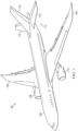
- Aircraft 100 has wing 102 and wing 104 attached to body 106. Aircraft 100 includes engine 108 attached to wing 102 and engine 110 attached to wing 104.
- Body 106 has tail section 112. Horizontal stabilizer 114, horizontal stabilizer 116, and vertical stabilizer 118 are attached to tail section 112 of body 106.
- Aircraft 100 is an example of an aircraft that can have a composite structure induction welded using the illustrative examples.
- an induction welded composite structure can be present in at least one of wing 102, wing 104, or body 106 of aircraft 100.
- Composite structure 202 can be induction welded in manufacturing environment 200.
- Composite structure 202 can be a composite component of aircraft 100.
- Composite structure 202 comprises first composite part 204, second composite part 206 welded to first composite part 204 at joint 208, and joint 208 between first composite part 204 and second composite part 206 comprising doped fibers 210.
- doped fibers 210 comprise fibers 211 doped with vertical graphene 212.
- fibers 211 comprise carbon-based fibers.
- Vertical graphene 212 can be deposited on fibers 211 using plasma enhanced chemical vapor deposition 214.
- doped fibers 210 comprise unidirectional fibers 216. In some illustrative examples, doped fibers 210 comprise woven fabric 218. After forming vertical graphene 212 on fibers 211, resin 220 is applied to fibers 211 to form doped prepreg ply 224. In some illustrative examples, resin 220 present in joint 208 is the same as resin 222 present in first composite part 204. In some illustrative examples, resin 220 present in doped prepreg ply 224 does not include conductive metal additives.
- doped prepreg ply 224 can be applied to one of first composite part 204 or second composite part 206. As depicted, doped prepreg ply 224 is a part of first composite part 204. In other illustrative examples, doped prepreg ply 224 is not present in first composite part 204. In some illustrative example, doped prepreg ply 224 is present in second composite part 206.
- doped prepreg ply 224 forms first surface 226.
- First surface 226 of first composite part 204 is in contact with second surface 228 of second composite part 206 in joint 208.
- First composite part 204 is formed of plurality of composite plies 230.
- Plurality of composite plies 230 are formed of fibers and resin 222.
- Plurality of composite plies 230 comprises structural composite plies 232.
- Structural composite plies 232 are present in first composite part 204 to contribute to material and structural characteristics of first composite part 204.
- Structural composite plies 232 are part of a design for first composite part 204.
- Plurality of composite plies 230 comprises surface composite plies 234 forming first surface 226.
- Surface composite plies 234 are not present to meet design specifications for strength or other characteristics of first composite part 204.
- doped prepreg ply 224 is one of surface composite plies 234. In some illustrative examples, doped prepreg ply 224 is applied after structural composite plies 232 sufficient to meet structural characteristics for first composite part 204.
- doped prepreg ply 224 is one of structural composite plies 232. In these illustrative examples, doped prepreg ply 224 is manufactured according to a manufacturing method for the respective structural ply after doping using plasma enhanced chemical vapor deposition 214.
- doped fibers 236 are also present at joint 208.
- doped fibers 236 comprise fibers 238 doped with vertical graphene 240.
- Vertical graphene 240 can be deposited on fibers 238 using plasma enhanced chemical vapor deposition 214.
- Second composite part 206 is formed of second plurality of composite plies 250.
- Second plurality of composite plies 250 is formed of fibers and resin 251.
- Second plurality of composite plies 250 comprises second structural composite plies 252.
- Second structural composite plies 252 are present in second composite part 206 to contribute to material and structural characteristics of second composite part 206.
- Second structural composite plies 252 are part of a design for second composite part 206.
- Joint 208 is formed between first composite part 204 and second composite part 206 by welding heat 262 generated in response to electromagnetic field 261 generated by induction welding coil 258.
- Induction welding coil 258 generates electromagnetic field 261 having current 260.
- At least one of doped fibers 210 or doped fibers 236 are present in joint 208 and generate welding heat 262 in response to electromagnetic field 261.
- Each of the processes of aircraft manufacturing and service method 600 may be performed or carried out by a system integrator, a third party, and/or an operator.
- the operator may be a customer.
- a system integrator may include, without limitation, any number of aircraft manufacturers and major-system subcontractors
- a third party may include, without limitation, any number of vendors, subcontractors, and suppliers
- an operator may be an airline, a leasing company, a military entity, a service organization, and so on.
- aircraft 700 is produced by aircraft manufacturing and service method 600 of Figure 6 and may include airframe 702 with plurality of systems 704 and interior 706.
- systems 704 include one or more of propulsion system 708, electrical system 710, hydraulic system 712, and environmental system 714. Any number of other systems may be included.
- the illustrative examples enable induction welding without undesirable effects to component quality or surface quality, and without the use of high precision tooling.
- the illustrative examples provide improved induction welding using doped fibers to increase heat generation locally in the joint between two composite parts.
- the illustrative examples comprise fibers doped with vertical graphene.
- the fibers can take the form of unidirectional carbon fibers.
- the fibers take the form of woven fibers.
- the fibers are doped with vertical graphene and pre-impregnated with materials using pre-pregging methods.
- the doped prepreg ply is then laid up at the faying surface of component laminates.
- composite parts can be processed in the same way, then joined together without additional materials or joining assistance.
- the illustrative examples provide the targeted application of doped fiber pre-pregs at the faying surface of the component laminate. By isolating the doped fiber pre-pregs at the joint the heat generation during induction heating is isolated at the joint interface.
- the illustrative examples enable the use of low-melt polymer composite materials with fewer impacts to structure quality.
- the illustrative examples increase the efficiency of the joining process in terms of energy consumption, processing rate, and requirements for tooling and equipment.
Landscapes
- Engineering & Computer Science (AREA)
- Mechanical Engineering (AREA)
- Textile Engineering (AREA)
- Chemical & Material Sciences (AREA)
- Dispersion Chemistry (AREA)
- Inorganic Chemistry (AREA)
- Physics & Mathematics (AREA)
- Plasma & Fusion (AREA)
- Lining Or Joining Of Plastics Or The Like (AREA)
- Moulding By Coating Moulds (AREA)
Abstract
Description
- The present disclosure relates generally to composite manufacturing and more specifically to induction welding of composite structures.
- Thermoplastic polymer composites are suitable for structural aircraft applications due to their mechanical performance capabilities. Thermoplastic polymer composites are able to be processed quickly and to be re-melted and re-formed. The ability to re-melt and re-form enables induction welding. induction welding is a process through which composite structures can be joined together without the use of chemical adhesive bonding or mechanical fasteners. induction welding can be performed without external heaters making direct contact with the structure.
- In induction welding, alternating current is induced in the carbon fibers, which melts the surrounding polymer. Two thermoplastic structures can be joined together by melting and re-crystallizing them together.
- Induction welding can be difficult to control due to a need for specific fiber contacts in order to induce currents in the structures. Induction welding can be difficult to control because induced currents can melt the whole structure, leading to deconsolidation and poor surface quality without precise tooling.
- Therefore, it would be desirable to have a method and apparatus that takes into account at least some of the issues discussed above, as well as other possible issues.
- According to the present disclosure, a composite structure, a method of welding two composite parts to form a composite structure and a method as defined in the independent claims are provided. Further embodiments are defined in the dependent claims. Although the scope is only defined by the claims, the below embodiments, examples, and aspects are present for aiding in understanding the background and advantages.
- An embodiment of the present disclosure provides a composite structure. The composite structure comprises a first composite part, a second composite part welded to the first composite part at a joint, and the joint between the first composite part and the second composite part comprising doped fibers.
- Another embodiment of the present disclosure provides a method of welding two composite parts to form a composite structure. A first composite part is formed with a doped prepreg ply comprising doped fibers at a first surface of the first composite part. A second composite part is positioned in contact with the first surface such that the doped prepreg ply is positioned at a joint between the first composite part and the second composite part. The first composite part and the second composite part are welded at the joint using heat generated by the doped fibers in response to an electromagnetic field.
- Yet another embodiment of the present disclosure provides a method. Fibers are doped to form doped fibers with increased conductivity. A doped prepreg ply is formed comprising the doped fibers. The doped prepreg ply is applied to a first composite part. A second composite part is positioned relative to the composite part such that the doped prepreg ply is positioned between the second composite part and the first composite part.
- The features and functions can be achieved independently in various embodiments of the present disclosure or may be combined in yet other embodiments in which further details can be seen with reference to the following description and drawings.
- The novel features believed characteristic of the illustrative embodiments are set forth in the appended claims. The illustrative embodiments, however, as well as a preferred mode of use, further objectives and features thereof, will best be understood by reference to the following detailed description of an illustrative embodiment of the present disclosure when read in conjunction with the accompanying drawings, wherein:
-
Figure 1 is an illustration of an aircraft in accordance with an illustrative embodiment; -
Figure 2 is an illustration of a block diagram of a manufacturing environment in accordance with an illustrative embodiment; -
Figure 3 is an illustration of an isometric view of induction welding a composite structure with a doped ply at the joint in accordance with an illustrative embodiment; -
Figure 4 is a flowchart of a method of welding two composite parts to form a composite structure in accordance with an illustrative embodiment; -
Figure 5 is a flowchart of a method of placing doped fibers between a first composite part and a second composite part in accordance with an illustrative embodiment; -
Figure 6 is an illustration of an aircraft manufacturing and service method in a form of a block diagram in accordance with an illustrative embodiment; and -
Figure 7 is an illustration of an aircraft in a form of a block diagram in which an illustrative embodiment may be implemented. - The illustrative examples recognize and take into account several considerations. The illustrative examples recognize and take into account that some challenges of induction welding could be overcome by isolating the current generation to only the surface of the structures to be joined, at the joint interface.
- The illustrative examples isolate the current generation at the joint interface by using at least one surface ply with functionalized fibers and increased conductivity.
- The fibers can be functionalized using Plasma Enhanced Chemical Vapor Deposition (PECVD) which causes vertical graphene to grow from the existing fibers, increasing the conductivity of the fibers. The increased conductivity increases the current which can be induced in the fibers at the joint interface, which increases the heat energy that can be generated there by a theoretical power of two.
- Turning now to
Figure 1 , an illustration of an aircraft is depicted in accordance with an illustrative embodiment.Aircraft 100 haswing 102 andwing 104 attached tobody 106.Aircraft 100 includesengine 108 attached towing 102 andengine 110 attached towing 104. -
Body 106 hastail section 112.Horizontal stabilizer 114,horizontal stabilizer 116, andvertical stabilizer 118 are attached totail section 112 ofbody 106. -
Aircraft 100 is an example of an aircraft that can have a composite structure induction welded using the illustrative examples. In some illustrative examples, an induction welded composite structure can be present in at least one ofwing 102,wing 104, orbody 106 ofaircraft 100. - Turning now to
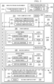
Figure 2 , an illustration of a block diagram of a manufacturing environment is depicted in accordance with an illustrative embodiment.Composite structure 202 can be induction welded inmanufacturing environment 200.Composite structure 202 can be a composite component ofaircraft 100. -
Composite structure 202 comprises firstcomposite part 204, secondcomposite part 206 welded to firstcomposite part 204 atjoint 208, and joint 208 between firstcomposite part 204 and secondcomposite part 206 comprising dopedfibers 210. - In some illustrative examples, doped
fibers 210 comprisefibers 211 doped withvertical graphene 212. In some illustrative examples,fibers 211 comprise carbon-based fibers.Vertical graphene 212 can be deposited onfibers 211 using plasma enhancedchemical vapor deposition 214. - In some illustrative examples, doped
fibers 210 compriseunidirectional fibers 216. In some illustrative examples, dopedfibers 210 comprisewoven fabric 218. After formingvertical graphene 212 onfibers 211,resin 220 is applied tofibers 211 to form dopedprepreg ply 224. In some illustrative examples,resin 220 present injoint 208 is the same asresin 222 present in firstcomposite part 204. In some illustrative examples,resin 220 present in dopedprepreg ply 224 does not include conductive metal additives. - After applying
resin 220 to dopedfibers 210, dopedprepreg ply 224 can be applied to one of firstcomposite part 204 or secondcomposite part 206. As depicted, dopedprepreg ply 224 is a part of firstcomposite part 204. In other illustrative examples, dopedprepreg ply 224 is not present in firstcomposite part 204. In some illustrative example, dopedprepreg ply 224 is present in secondcomposite part 206. - When present in first
composite part 204, doped prepreg ply 224 formsfirst surface 226.First surface 226 of firstcomposite part 204 is in contact withsecond surface 228 of secondcomposite part 206 in joint 208. - First
composite part 204 is formed of plurality of composite plies 230. Plurality ofcomposite plies 230 are formed of fibers andresin 222. Plurality ofcomposite plies 230 comprises structural composite plies 232. Structural composite plies 232 are present in firstcomposite part 204 to contribute to material and structural characteristics of firstcomposite part 204. Structural composite plies 232 are part of a design for firstcomposite part 204. - Plurality of
composite plies 230 comprises surface composite plies 234 formingfirst surface 226. Surface composite plies 234 are not present to meet design specifications for strength or other characteristics of firstcomposite part 204. - In some illustrative examples, doped
prepreg ply 224 is one of surface composite plies 234. In some illustrative examples, dopedprepreg ply 224 is applied after structural composite plies 232 sufficient to meet structural characteristics for firstcomposite part 204. - In some illustrative examples, doped
prepreg ply 224 is one of structural composite plies 232. In these illustrative examples, dopedprepreg ply 224 is manufactured according to a manufacturing method for the respective structural ply after doping using plasma enhancedchemical vapor deposition 214. - As depicted, doped
fibers 236 are also present at joint 208. In some illustrative examples, dopedfibers 236 comprisefibers 238 doped withvertical graphene 240.Vertical graphene 240 can be deposited onfibers 238 using plasma enhancedchemical vapor deposition 214. - In some illustrative examples, doped
fibers 236 compriseunidirectional fibers 242. In some illustrative examples, dopedfibers 236 comprise wovenfabric 244. After formingvertical graphene 240 onfibers 238,resin 246 is applied tofibers 238 to form dopedprepreg ply 248. In some illustrative examples,resin 246 present in joint 208 is the same asresin 251 present in secondcomposite part 206. In some illustrative examples,resin 246 present in dopedprepreg ply 248 does not include conductive metal additives. - Second
composite part 206 is formed of second plurality of composite plies 250. Second plurality ofcomposite plies 250 is formed of fibers andresin 251. Second plurality ofcomposite plies 250 comprises second structural composite plies 252. Second structural composite plies 252 are present in secondcomposite part 206 to contribute to material and structural characteristics of secondcomposite part 206. Second structural composite plies 252 are part of a design for secondcomposite part 206. - Second plurality of
composite plies 250 comprises second surface composite plies 254 formingsecond surface 228. Second surface composite plies 254 are not present to meet design specifications for strength or other characteristics of secondcomposite part 206. - In some illustrative examples, doped
prepreg ply 248 is one of second surface composite plies 254. In some illustrative examples, dopedprepreg ply 248 is applied after second structural composite plies 252 sufficient to meet structural characteristics for secondcomposite part 206. - In some illustrative examples, doped
prepreg ply 248 is one of second structural composite plies 252. In these illustrative examples, dopedprepreg ply 248 is manufactured according to a manufacturing method for the respective structural ply after doping using plasma enhancedchemical vapor deposition 214. - As depicted, doped prepreg ply 224 forms
first surface 226 of firstcomposite part 204. As depicted, doped prepreg ply 248 formssecond surface 228 of secondcomposite part 206. Doped prepreg ply 224 and dopedprepreg ply 248 are present in joint 208. - In some illustrative examples, doped
fibers 210 are isolated within joint 208. - In some illustrative examples, doped
fibers 210 are part of a structural ply of one of firstcomposite part 204 or secondcomposite part 206. In some illustrative examples, dopedfibers 210 are part of an additional ply present for joining firstcomposite part 204 and secondcomposite part 206 independently of a structural design for firstcomposite part 204 and a second structural design for secondcomposite part 206. -
Doped fibers 210 in dopedprepreg ply 224 are more conductive than conventional prepreg plies. The increase in conductivity can increase heat generation in dopedprepreg ply 224. By locating doped prepreg ply 224 in joint 208, heat during induction welding can be located within joint 208. - Doped fibers in joint 208, such as doped
fibers 210 or dopedfibers 236, enable induction welding without undesirable effects to resultingcomposite structure 202. Doped fibers in joint 208 enable induction welding without component deconsolidation and without reduced surface quality, without the need for high precision tooling. -
Doped fibers 210 isolatewelding heat 262 to plies withinset distance 256 from dopedfibers 210 by increased heat generation of dopedfibers 210.Doped fibers 236 isolatewelding heat 262 to plies withinset distance 256 from dopedfibers 236 by increased heat generation of dopedfibers 236. By applying dopedfibers 210 and dopedfibers 236 only within joint 208,welding heat 262 is isolated at or nearjoint 208. - Increased heat generation of doped
fibers 210 and dopedfibers 236 enablesinduction welding coil 258 to operate at current 260. Current 260 is a lower operating current than conventional induction welding. By utilizing a reduced current, current 260,induction welding coil 258 reduces or eliminates heat generation in the remainder of firstcomposite part 204 and secondcomposite part 206. -
Joint 208 is formed between firstcomposite part 204 and secondcomposite part 206 by weldingheat 262 generated in response to electromagnetic field 261 generated byinduction welding coil 258.Induction welding coil 258 generates electromagnetic field 261 having current 260. At least one of dopedfibers 210 or dopedfibers 236 are present in joint 208 and generatewelding heat 262 in response to electromagnetic field 261. - By using at least one of doped prepreg ply 224 with doped
fibers 210 or doped prepreg ply 248 with dopedfibers 236 to heat joint 208, firstcomposite part 204 and secondcomposite part 206 can be processed in a conventional way, and then joined together without additional materials or joining assistance. Plasma enhancedchemical vapor deposition 214 process todope fibers 211 and the pre-impregnation of dopedfibers 210 results in doped prepreg ply 224 with increased conductivity without any changes to the part design, joint 208 interface, or processing methods. - The illustration of
manufacturing environment 200 inFigure 2 is not meant to imply physical or architectural limitations to the manner in which an illustrative embodiment may be implemented. Other components in addition to or in place of the ones illustrated may be used. Some components may be unnecessary. Also, the blocks are presented to illustrate some functional components. One or more of these blocks may be combined, divided, or combined and divided into different blocks when implemented in an illustrative embodiment. - For example, more than one doped ply can be present in at least one of first
composite part 204 or secondcomposite part 206. As another example, only one of doped prepreg ply 224 or dopedprepreg ply 248 can be present incomposite structure 202. Althoughresin 222 andresin 251 are discussed separately,resin 222 can be the same asresin 251. In some illustrative examples,resin 222,resin 251,resin 220, andresin 246 can be the same. - In some illustrative examples, doped
fibers 210 and dopedfibers 236 are the same. In some illustrative examples, dopedfibers 210 and dopedfibers 236 areunidirectional fibers 216 andunidirectional fibers 242. In some illustrative examples, dopedfibers 210 and dopedfibers 236 are wovenfabric 218 andwoven fabric 244. - Turning now to
Figure 3 , an illustration of an isometric view of induction welding a composite structure with a doped ply at the joint is depicted in accordance with an illustrative embodiment.Composite structure 302 inview 300 is a physical implementation ofcomposite structure 202 ofFigure 2 . -
Composite structure 302 comprises firstcomposite part 304, secondcomposite part 306, and joint 308 between firstcomposite part 304 and secondcomposite part 306.Joint 308 comprises doped fibers. - As depicted, first
composite part 304 comprisesfirst surface 310.First surface 310 comprises dopedprepreg ply 312. Doped prepreg ply 312 comprises the doped fibers. - Doped prepreg ply 312 is in contact with second
composite part 306. In some illustrative examples, secondcomposite part 306 comprises a doped composite ply in place of or in addition to doped prepreg ply 312 of firstcomposite part 304. - To inductively weld first
composite part 304 to secondcomposite part 306,inductive welding coil 314 is positioned relative to firstcomposite part 304 and secondcomposite part 306.Inductive welding coil 314 can have a reduced current in welding firstcomposite part 304 and secondcomposite part 306 due to doped fibers in dopedprepreg ply 312. - Due to a reduced current of
inductive welding coil 314, heat affectedzone 316 of firstcomposite part 304 and secondcomposite part 306 is reduced. Doped prepreg ply 312 isolates welding heat to plies withinset distance 318 from the doped fibers by increased heat generation of the doped fibers. - Turning now to
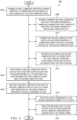
Figure 4 , a flowchart of a method of welding two composite parts to form a composite structure is depicted in accordance with an illustrative embodiment.Method 400 can be used to weld together firstcomposite part 204 and secondcomposite part 206 ofFigure 2 .Method 400 can be used to weld together firstcomposite part 304 and secondcomposite part 306 ofFigure 3 . - A first composite part is formed with a doped prepreg ply comprising doped fibers at a first surface of the first composite part (operation 402). A second composite part is positioned in contact with the first surface such that the doped prepreg ply is positioned at a joint between the first composite part and the second composite part (operation 404). The first composite part and the second composite part are welded at the joint using heat generated by the doped fibers in response to an electromagnetic field (operation 406). Afterwards,
method 400 terminates. - In some illustrative examples,
method 400 applies an electromagnetic field having a reduced current to the joint (operation 414). The reduced current induces heat generation in the doped fibers. The reduced current does not generate undesirable amounts of heat in non-doped fibers. - In some illustrative examples, forming the first composite part with the doped prepreg ply comprises forming the first composite part with the doped prepreg ply replacing a structural ply (operation 408). In some illustrative examples, when the doped prepreg ply replaces the structural ply, the doped prepreg ply has the same fiber orientation as the structural ply.
- In some illustrative examples,
method 400 forms the second composite part with a second doped prepreg ply comprising doped fibers at a second surface of the second composite part (operation 410). In some illustrative examples, positioning the second composite part in contact with the first surface comprises positioning the second surface in contact with the first surface (operation 412). - In some illustrative examples,
method 400 isolates welding heat to plies within a set distance from the doped fibers by increased heat generation of the doped fibers (operation 416). Isolating heat to plies within the set distance of the doped fibers limits the heat applied to the first composite part and the second composite part outside of the joint. Isolating heat to plies within the set distance of the doped fibers can result in a higher quality composite structure than conventional induction welding. - Turning now to
Figure 5 , a flowchart of a method of placing doped fibers between a first composite part and a second composite part is depicted in accordance with an illustrative embodiment.Method 500 can be used to weld together firstcomposite part 204 and secondcomposite part 206 ofFigure 2 .Method 500 can be used to weld together firstcomposite part 304 and secondcomposite part 306 ofFigure 3 . -
Method 500 dopes fibers to form doped fibers with increased conductivity (operation 502).Method 500 forms a doped prepreg ply comprising the doped fibers (operation 504).Method 500 applies the doped prepreg ply to a first composite part (operation 506).Method 500 positions a second composite part relative to the composite part such that the doped prepreg ply is positioned between the second composite part and the first composite part (operation 508). Afterwards,method 500 terminates. - In some illustrative examples, doping the fibers comprises forming vertical graphene on the fibers to form doped fibers (operation 510). In some illustrative examples, forming vertical graphene on the fibers comprises applying plasma enhanced chemical vapor deposition to the fibers (operation 512).
- In some illustrative examples, forming the doped prepreg ply comprises infusing resin into a woven fabric comprising the doped fibers (operation 514). In some illustrative examples, forming the doped prepreg ply comprises mixing unidirectional fibers comprising the doped fibers with a resin (operation 516). In some illustrative examples, forming the doped prepreg ply comprises applying a same resin to the doped fibers as is contained in the first composite part (operation 518). In some illustrative examples, the resin present in the doped prepreg ply does not include conductive metal additives (operation 520).
- In some illustrative examples,
method 500 welds the first composite part and the second composite part while isolating welding heat to plies within a set distance from the doped prepreg ply by increased heat generation of the doped prepreg ply (operation 522). The increased heat generation of the doped fibers in the doped prepreg ply can allow for the induction welding coil to operate at a reduced current. - As used herein, the phrase "at least one of," when used with a list of items, means different combinations of one or more of the listed items may be used and only one of each item in the list may be needed. For example, "at least one of item A, item B, or item C" may include, without limitation, item A, item A and item B, or item B. This example also may include item A, item B, and item C or item B and item C. Of course, any combinations of these items may be present. In other examples, "at least one of" may be, for example, without limitation, two of item A; one of item B; and ten of item C; four of item B and seven of item C; or other suitable combinations. The item may be a particular object, thing, or a category. In other words, at least one of means any combination items and number of items may be used from the list but not all of the items in the list are required.
- As used herein, "a number of," when used with reference to items means one or more items.
- The flowcharts and block diagrams in the different depicted embodiments illustrate the architecture, functionality, and operation of some possible implementations of apparatuses and methods in an illustrative embodiment. In this regard, each block in the flowcharts or block diagrams may represent at least one of a module, a segment, a function, or a portion of an operation or step.
- In some alternative implementations of an illustrative embodiment, the function or functions noted in the blocks may occur out of the order noted in the figures. For example, in some cases, two blocks shown in succession may be executed substantially concurrently, or the blocks may sometimes be performed in the reverse order, depending upon the functionality involved. Also, other blocks may be added in addition to the illustrated blocks in a flowchart or block diagram. Some blocks may be optional. For example,
operation 408 throughoperation 416 may be optional. For example,operation 510 throughoperation 522 may be optional. - Illustrative embodiments of the present disclosure may be described in the context of aircraft manufacturing and
service method 600 as shown inFigure 6 andaircraft 700 as shown inFigure 7 . Turning first toFigure 6 , an illustration of an aircraft manufacturing and service method in a form of a block diagram is depicted in accordance with an illustrative embodiment. During pre-production, aircraft manufacturing andservice method 600 may include specification anddesign 602 ofaircraft 700 inFigure 7 andmaterial procurement 604. - During production, component and
subassembly manufacturing 606 andsystem integration 608 ofaircraft 700 takes place. Thereafter,aircraft 700 may go through certification anddelivery 610 in order to be placed inservice 612. While inservice 612 by a customer,aircraft 700 is scheduled for routine maintenance andservice 614, which may include modification, reconfiguration, refurbishment, or other maintenance and service. - Each of the processes of aircraft manufacturing and
service method 600 may be performed or carried out by a system integrator, a third party, and/or an operator. In these examples, the operator may be a customer. For the purposes of this description, a system integrator may include, without limitation, any number of aircraft manufacturers and major-system subcontractors; a third party may include, without limitation, any number of vendors, subcontractors, and suppliers; and an operator may be an airline, a leasing company, a military entity, a service organization, and so on. - With reference now to
Figure 7 , an illustration of an aircraft in a form of a block diagram is depicted in which an illustrative embodiment may be implemented. In this example,aircraft 700 is produced by aircraft manufacturing andservice method 600 ofFigure 6 and may includeairframe 702 with plurality ofsystems 704 and interior 706. Examples ofsystems 704 include one or more ofpropulsion system 708,electrical system 710,hydraulic system 712, andenvironmental system 714. Any number of other systems may be included. - Apparatuses and methods embodied herein may be employed during at least one of the stages of aircraft manufacturing and
service method 600. One or more illustrative embodiments may be manufactured or used during at least one of component andsubassembly manufacturing 606,system integration 608, inservice 612, or maintenance andservice 614 ofFigure 6 . - The illustrative examples enable induction welding without undesirable effects to component quality or surface quality, and without the use of high precision tooling. The illustrative examples provide improved induction welding using doped fibers to increase heat generation locally in the joint between two composite parts.
- The illustrative examples comprise fibers doped with vertical graphene. In some illustrative examples, the fibers can take the form of unidirectional carbon fibers. In other illustrative examples, the fibers take the form of woven fibers. The fibers are doped with vertical graphene and pre-impregnated with materials using pre-pregging methods. The doped prepreg ply is then laid up at the faying surface of component laminates. In the illustrative examples, composite parts can be processed in the same way, then joined together without additional materials or joining assistance.
- The illustrative examples provide the targeted application of doped fiber pre-pregs at the faying surface of the component laminate. By isolating the doped fiber pre-pregs at the joint the heat generation during induction heating is isolated at the joint interface.
- The illustrative examples enable the use of low-melt polymer composite materials with fewer impacts to structure quality. The illustrative examples increase the efficiency of the joining process in terms of energy consumption, processing rate, and requirements for tooling and equipment.
- The description of the different illustrative embodiments has been presented for purposes of illustration and description, and is not intended to be exhaustive or limited to the embodiments in the form disclosed. Many modifications and variations will be apparent to those of ordinary skill in the art. Further, different illustrative embodiments may provide different features as compared to other illustrative embodiments. The embodiment or embodiments selected are chosen and described in order to best explain the principles of the embodiments, the practical application, and to enable others of ordinary skill in the art to understand the disclosure for various embodiments with various modifications as are suited to the particular use contemplated. Although the scope is only defined by the claims, the below embodiments, examples, and aspects, worded as clauses, are present for aiding in understanding the background and advantages.
- Clause 1. A composite structure comprising:
- a first composite part;
- a second composite part welded to the first composite part at a joint; and
- the joint between the first composite part and the second composite part comprising doped fibers.
-
Clause 2. The composite structure of Clause 1, wherein the doped fibers comprise fibers doped with vertical graphene. - Clause 3. The composite structure of
Clause 1 or 2, wherein the doped fibers comprise unidirectional fibers. - Clause 4. The composite structure of any of the preceding Clauses, wherein the doped fibers comprise woven fabric.
- Clause 5. The composite structure of any of the preceding Clauses , wherein the doped fibers are isolated within the joint.
- Clause 6. The composite structure of any of the preceding Clauses , wherein a resin present in the joint is the same as resin present in the first composite part.
- Clause 7. The composite structure of any of the preceding Clauses , wherein the doped fibers are part of a structural ply of one of the first composite part or the second composite part.
- Clause 8. The composite structure of any of the preceding Clauses , wherein the doped fibers are part of an additional ply present for joining the first composite part and the second composite part independently of a structural design for the first composite part and a second structural design for the second composite part.
- Clause 9. A method of welding two composite parts to form a composite structure, the method comprising:
- forming a first composite part with a doped prepreg ply comprising doped fibers at a first surface of the first composite part;
- positioning a second composite part in contact with the first surface such that the doped prepreg ply is positioned at a joint between the first composite part and the second composite part; and
- welding the first composite part and the second composite part at the joint using heat generated by the doped fibers in response to an electromagnetic field.
- Clause 10. The method of Clause 9, further comprising:
applying an electromagnetic field having a reduced current to the joint. - Clause 11. The method of Clause 9 or 10, wherein forming the first composite part with the doped prepreg ply comprises forming the first composite part with the doped prepreg ply replacing a structural ply.
- Clause 12. The method of Clause 9, 10 or 11 further comprising:
- forming the second composite part with a second doped prepreg ply comprising doped fibers at a second surface of the second composite part; and
- wherein positioning the second composite part in contact with the first surface comprises positioning the second surface in contact with the first surface.
- Clause 13. The method of Clause 9, 10, 11 or 12 further comprising:
isolating welding heat to plies within a set distance from the doped fibers by increased heat generation of the doped fibers. - Clause 14. A method comprising:
- doping fibers to form doped fibers with increased conductivity;
- forming a doped prepreg ply comprising the doped fibers;
- applying the doped prepreg ply to a first composite part; and
- positioning a second composite part relative to the first composite part such that the doped prepreg ply is positioned between the second composite part and the first composite part.
- Clause 15. The method of Clause 14, wherein doping the fibers comprises forming vertical graphene on the fibers to form doped fibers.
- Clause 16. The method of Clause 14 or 15, wherein forming vertical graphene on the fibers comprises applying plasma enhanced chemical vapor deposition to the fibers.
- Clause 17. The method of Clause 14, 15 or 16, wherein forming the doped prepreg ply comprises infusing resin into a woven fabric comprising the doped fibers.
- Clause 18. The method of Clause 14, 15, 16 or 17, wherein forming the doped prepreg ply comprises mixing unidirectional fibers comprising the doped fibers with a resin.
- Clause 19. The method of any of clauses 14 to 18, wherein forming the doped prepreg ply comprises applying a same resin to the doped fibers as is contained in the first composite part.
- Clause 20. The method of any of Clauses 14 to 19, wherein resin present in the doped prepreg ply does not include conductive metal additives.
- Clause 21. The method of any of Clauses 14 to 20 further comprising:
welding the first composite part and the second composite part while isolating welding heat to plies within a set distance from the doped prepreg ply by increased heat generation of the doped prepreg ply.
Claims (15)
- A composite structure (202, 302) comprising:a first composite part (204, 304);a second composite part (206, 306) welded to the first composite part (204, 304) at a joint (208, 308); andthe joint (208, 308) between the first composite part (204, 304) and the second composite part (206, 306) comprising doped fibers (210 or 236).
- The composite structure (202, 302) of claim 1, wherein the doped fibers (210 or 236) comprise fibers (211 or 238) doped with vertical graphene (212 or 240).
- The composite structure (202, 302) of claim 1 or 2, wherein the doped fibers (210 or 236) comprise unidirectional fibers (216 or 242).
- The composite structure (202, 302) of claim 1, 2 or 3, wherein the doped fibers (210 or 236) comprise woven fabric (218 or 244).
- The composite structure (202, 302) of any of the preceding claims, wherein the doped fibers (210 or 236) are isolated within the joint (208, 308).
- The composite structure (202, 302) of any of the preceding claims, wherein a resin (220 or 246) present in the joint (208, 308) is the same as resin (222) present in the first composite part (204, 304).
- The composite structure (202, 302) of any of the preceding claims, wherein the doped fibers (210 or 236) are part of a structural ply (232 or 252) of one of the first composite part (204, 304) or the second composite part (206, 306) .
- The composite structure (202, 302) of any of the preceding claims, wherein the doped fibers (210 or 236) are part of an additional ply present for joining the first composite part (204, 304) and the second composite part (206, 306) independently of a structural design for the first composite part (204, 304) and a second structural design for the second composite part (206, 306) .
- A method (400) of welding two composite parts to form a composite structure (202, 302), the method comprising:forming (402) a first composite part (204, 304) with a doped prepreg ply (224, 312) comprising doped fibers (210) at a first surface (226) of the first composite part (204, 304);positioning (404) a second composite part (206, 306) in contact with the first surface (226) such that the doped prepreg ply (224, 312) is positioned at a joint (208, 308) between the first composite part (204, 304) and the second composite part (206, 306); andwelding (406) the first composite part (204, 304) and the second composite part (206, 306) at the joint (208, 308) using heat generated by the doped fibers (210) in response to an electromagnetic field (261).
- The method (400) of claim 9, further comprising:
applying (414) an electromagnetic field (261) having a reduced current (260) to the joint (208, 308). - The method (400) of claim 9 or 10, wherein (408) forming the first composite part (204, 304) with the doped prepreg ply (224, 312) comprises forming the first composite part (204, 304) with the doped prepreg ply (224, 312) replacing a structural ply (232).
- The method (400) of claim 9, 10 or 11 further comprising:forming (410) the second composite part (206, 306) with a second doped prepreg ply (248) comprising doped fibers (236) at a second surface (228) of the second composite part (206, 306); andwherein (412) positioning the second composite part (206, 306) in contact with the first surface (226) comprises positioning the second surface (228) in contact with the first surface (226).
- The method (400) of any of claims 9 to 12 further comprising:
isolating (416) welding heat (262) to plies within a set distance (256, 318) from the doped fibers (210 or 236) by increased heat generation of the doped fibers (210 or 236) . - A method (500) comprising:doping (502) fibers (211) to form doped fibers (210) with increased conductivity;forming (504) a doped prepreg ply (224, 312) comprising the doped fibers (210);applying (506) the doped prepreg ply (224, 312) to a first composite part (204, 304); andpositioning (508) a second composite part (206, 306) relative to the first composite part (204, 304) such that the doped prepreg ply (224, 312) is positioned between the second composite part (206, 306) and the first composite part (204, 304).
- The method (500) of claim 14, wherein (510) doping the fibers (211) comprises forming vertical graphene (212) on the fibers (211) to form doped fibers (210 or 236), preferably wherein(512) forming vertical graphene (212) on the fibers (211) comprises applying plasma enhanced chemical vapor deposition (214) to the fibers (211); and/orwherein (514) forming the doped prepreg ply (224, 312) comprises infusing resin (220) into a woven fabric (218) comprising the doped fibers (210); and/orwherein (516) forming the doped prepreg ply (224, 312) comprises mixing unidirectional fibers (216) comprising the doped fibers (210) with a resin (220); and/or wherein (518) forming the doped prepreg ply (224, 312) comprises applying a same resin (220, 222) to the doped fibers (210 or 236) as is contained in the first composite part (204, 304); and/orwherein (520) resin (220) present in the doped prepreg ply (224, 312) does not include conductive metal additives; and/orfurther comprising:
welding (522) the first composite part (204, 304) and the second composite part (206, 306) while isolating welding heat (262) to plies within a set distance (256, 318) from the doped prepreg ply (224, 312) by increased heat generation of the doped prepreg ply (224, 312).
Applications Claiming Priority (1)
| Application Number | Priority Date | Filing Date | Title |
|---|---|---|---|
| US18/464,862 US20250083397A1 (en) | 2023-09-11 | 2023-09-11 | Induction Welding of Composite Structures |
Publications (1)
| Publication Number | Publication Date |
|---|---|
| EP4520511A1 true EP4520511A1 (en) | 2025-03-12 |
Family
ID=91582094
Family Applications (1)
| Application Number | Title | Priority Date | Filing Date |
|---|---|---|---|
| EP24182564.5A Pending EP4520511A1 (en) | 2023-09-11 | 2024-06-17 | Induction welding of composite structures |
Country Status (4)
| Country | Link |
|---|---|
| US (1) | US20250083397A1 (en) |
| EP (1) | EP4520511A1 (en) |
| JP (1) | JP2025040387A (en) |
| CN (1) | CN119589966A (en) |
Citations (2)
| Publication number | Priority date | Publication date | Assignee | Title |
|---|---|---|---|---|
| JPH03248832A (en) * | 1990-02-28 | 1991-11-06 | Fuji Heavy Ind Ltd | Joining method of fiber-reinforced composite |
| US20190358909A1 (en) * | 2018-05-24 | 2019-11-28 | Airbus Operations (S.A.S.) | Method for assembling by welding at least two components of composite material and assembly of components of composite material obtained in this manner |
-
2023
- 2023-09-11 US US18/464,862 patent/US20250083397A1/en active Pending
-
2024
- 2024-05-30 JP JP2024088111A patent/JP2025040387A/en active Pending
- 2024-06-17 EP EP24182564.5A patent/EP4520511A1/en active Pending
- 2024-06-26 CN CN202410834835.0A patent/CN119589966A/en active Pending
Patent Citations (2)
| Publication number | Priority date | Publication date | Assignee | Title |
|---|---|---|---|---|
| JPH03248832A (en) * | 1990-02-28 | 1991-11-06 | Fuji Heavy Ind Ltd | Joining method of fiber-reinforced composite |
| US20190358909A1 (en) * | 2018-05-24 | 2019-11-28 | Airbus Operations (S.A.S.) | Method for assembling by welding at least two components of composite material and assembly of components of composite material obtained in this manner |
Also Published As
| Publication number | Publication date |
|---|---|
| JP2025040387A (en) | 2025-03-24 |
| CN119589966A (en) | 2025-03-11 |
| US20250083397A1 (en) | 2025-03-13 |
Similar Documents
| Publication | Publication Date | Title |
|---|---|---|
| AU2020201610B2 (en) | Fabrication of composite laminates using temporarily stitched preforms | |
| RU2767025C1 (en) | Method for welding parts made of a thermoplastic material | |
| CA2888974C (en) | Joining composite components using low temperature thermoplastic film fusion | |
| US10377084B2 (en) | Conformable induction coils for induction joining | |
| EP3112131B1 (en) | Welding thermoplastic structures | |
| US9517594B2 (en) | Composite structure having a stabilizing element | |
| US8884201B2 (en) | Systems and methods for fabrication of thermoplastic components | |
| EP2709825B1 (en) | Thermoplastic induction welding apparatus and method | |
| KR20160137355A (en) | High rate production fiber placement system and method | |
| US20150125655A1 (en) | Laminated composite radius filler with geometric shaped filler element and method of forming the same | |
| US10899081B2 (en) | Methods and apparatus for thermoplastic welding | |
| US20110039057A1 (en) | Laminated composite rod and fabrication method | |
| US20250083397A1 (en) | Induction Welding of Composite Structures | |
| EP4140876A2 (en) | Control surface and method of making the same | |
| US11220064B2 (en) | Methods and apparatus for fabricating panels | |
| TWI892299B (en) | Thermoplastic composite induction welding method and monocoque structure manufacturing method | |
| McCarville et al. | Processing and joining of thermoplastic composites | |
| US11186045B2 (en) | Systems for manufacturing modular rotor blades | |
| CN120019949A (en) | Induction welding method for thermoplastic fiber composite materials and method for manufacturing hard shell type hollow structure | |
| EP4501597B1 (en) | Consolidating thermoplastic material with induction heating coil and heating plate(s) | |
| US20250282097A1 (en) | Methods and systems for reinforcing additively manufactured structures | |
| CN119175890A (en) | Welding-desoldering reversible composite material connection method | |
| CN122071141A (en) | Polymer-based composite joints, systems and methods for treating polymer-based composite joints |
Legal Events
| Date | Code | Title | Description |
|---|---|---|---|
| PUAI | Public reference made under article 153(3) epc to a published international application that has entered the european phase |
Free format text: ORIGINAL CODE: 0009012 |
|
| STAA | Information on the status of an ep patent application or granted ep patent |
Free format text: STATUS: THE APPLICATION HAS BEEN PUBLISHED |
|
| AK | Designated contracting states |
Kind code of ref document: A1 Designated state(s): AL AT BE BG CH CY CZ DE DK EE ES FI FR GB GR HR HU IE IS IT LI LT LU LV MC ME MK MT NL NO PL PT RO RS SE SI SK SM TR |
|
| STAA | Information on the status of an ep patent application or granted ep patent |
Free format text: STATUS: REQUEST FOR EXAMINATION WAS MADE |
|
| 17P | Request for examination filed |
Effective date: 20250715 |
|
| GRAP | Despatch of communication of intention to grant a patent |
Free format text: ORIGINAL CODE: EPIDOSNIGR1 |
|
| STAA | Information on the status of an ep patent application or granted ep patent |
Free format text: STATUS: GRANT OF PATENT IS INTENDED |
|
| RIC1 | Information provided on ipc code assigned before grant |
Ipc: B29C 65/36 20060101AFI20251030BHEP Ipc: B29L 31/30 20060101ALN20251030BHEP |
|
| RIC1 | Information provided on ipc code assigned before grant |
Ipc: B29C 65/36 20060101AFI20251113BHEP Ipc: B29L 31/30 20060101ALN20251113BHEP |
|
| INTG | Intention to grant announced |
Effective date: 20251127 |
|
| GRAJ | Information related to disapproval of communication of intention to grant by the applicant or resumption of examination proceedings by the epo deleted |
Free format text: ORIGINAL CODE: EPIDOSDIGR1 |
|
| STAA | Information on the status of an ep patent application or granted ep patent |
Free format text: STATUS: REQUEST FOR EXAMINATION WAS MADE |
|
| INTC | Intention to grant announced (deleted) |