EP4520507A1 - Additive manufacturing method, additive manufacturing equipment, and program - Google Patents
Additive manufacturing method, additive manufacturing equipment, and program Download PDFInfo
- Publication number
- EP4520507A1 EP4520507A1 EP23819533.3A EP23819533A EP4520507A1 EP 4520507 A1 EP4520507 A1 EP 4520507A1 EP 23819533 A EP23819533 A EP 23819533A EP 4520507 A1 EP4520507 A1 EP 4520507A1
- Authority
- EP
- European Patent Office
- Prior art keywords
- fiber
- manufacturing
- head unit
- reinforced resin
- filament
- Prior art date
- Legal status (The legal status is an assumption and is not a legal conclusion. Google has not performed a legal analysis and makes no representation as to the accuracy of the status listed.)
- Pending
Links
Images


Classifications
-
- B—PERFORMING OPERATIONS; TRANSPORTING
- B29—WORKING OF PLASTICS; WORKING OF SUBSTANCES IN A PLASTIC STATE IN GENERAL
- B29C—SHAPING OR JOINING OF PLASTICS; SHAPING OF MATERIAL IN A PLASTIC STATE, NOT OTHERWISE PROVIDED FOR; AFTER-TREATMENT OF THE SHAPED PRODUCTS, e.g. REPAIRING
- B29C64/00—Additive manufacturing, i.e. manufacturing of three-dimensional [3D] objects by additive deposition, additive agglomeration or additive layering, e.g. by 3D printing, stereolithography or selective laser sintering
- B29C64/10—Processes of additive manufacturing
- B29C64/106—Processes of additive manufacturing using only liquids or viscous materials, e.g. depositing a continuous bead of viscous material
- B29C64/118—Processes of additive manufacturing using only liquids or viscous materials, e.g. depositing a continuous bead of viscous material using filamentary material being melted, e.g. fused deposition modelling [FDM]
-
- B—PERFORMING OPERATIONS; TRANSPORTING
- B29—WORKING OF PLASTICS; WORKING OF SUBSTANCES IN A PLASTIC STATE IN GENERAL
- B29C—SHAPING OR JOINING OF PLASTICS; SHAPING OF MATERIAL IN A PLASTIC STATE, NOT OTHERWISE PROVIDED FOR; AFTER-TREATMENT OF THE SHAPED PRODUCTS, e.g. REPAIRING
- B29C64/00—Additive manufacturing, i.e. manufacturing of three-dimensional [3D] objects by additive deposition, additive agglomeration or additive layering, e.g. by 3D printing, stereolithography or selective laser sintering
- B29C64/30—Auxiliary operations or equipment
- B29C64/307—Handling of material to be used in additive manufacturing
- B29C64/321—Feeding
-
- B—PERFORMING OPERATIONS; TRANSPORTING
- B33—ADDITIVE MANUFACTURING TECHNOLOGY
- B33Y—ADDITIVE MANUFACTURING, i.e. MANUFACTURING OF THREE-DIMENSIONAL [3D] OBJECTS BY ADDITIVE DEPOSITION, ADDITIVE AGGLOMERATION OR ADDITIVE LAYERING, e.g. BY 3D PRINTING, STEREOLITHOGRAPHY OR SELECTIVE LASER SINTERING
- B33Y10/00—Processes of additive manufacturing
-
- B—PERFORMING OPERATIONS; TRANSPORTING
- B33—ADDITIVE MANUFACTURING TECHNOLOGY
- B33Y—ADDITIVE MANUFACTURING, i.e. MANUFACTURING OF THREE-DIMENSIONAL [3D] OBJECTS BY ADDITIVE DEPOSITION, ADDITIVE AGGLOMERATION OR ADDITIVE LAYERING, e.g. BY 3D PRINTING, STEREOLITHOGRAPHY OR SELECTIVE LASER SINTERING
- B33Y30/00—Apparatus for additive manufacturing; Details thereof or accessories therefor
Definitions
- the present invention relates to an additive manufacturing method, an additive manufacturing device, and a program.
- FDM fused deposition molding
- Patent Literature 1 WO2015/182675
- an object of the present invention is to provide an additive manufacturing method, an additive manufacturing device, and a program capable of performing intended manufacturing without causing meandering even when a filament including a twisted continuous reinforcing fiber bundle is used.
- the present invention includes the following configurations.
- An additive manufacturing device shown here is a device for creating a manufactured object by a fused deposition molding method, and a fiber-reinforced resin filament obtained by impregnating a twisted continuous reinforcing fiber bundle with a resin is used as a manufacturing material.
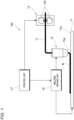
- FIG. 1 is a schematic configuration diagram showing an FDM-type additive manufacturing device 100.
- the additive manufacturing device 100 includes a filament feeding unit 13 that feeds a fiber-reinforced resin filament (hereinafter, also referred to as a filament) 11, a head unit 15, a manufacturing table 17, a molding driving unit 19, and a control unit 21.
- a filament feeding unit 13 that feeds a fiber-reinforced resin filament (hereinafter, also referred to as a filament) 11, a head unit 15, a manufacturing table 17, a molding driving unit 19, and a control unit 21.
- the filament feeding unit 13 includes a pair of driving rollers 13a that sandwich the filament 11, and a driving unit (not shown) such as a motor that rotationally drives at least one of the driving rollers 13a.
- the head unit 15 includes a heating unit (not shown) that thermally melts the fed filament 11, and a nozzle 15a that extrudes a manufacturing material melted by the heating unit.
- a cutting unit such as a cutter or a laser cutting device that cuts a reinforcing fiber included in the filament 11 may be provided.
- the manufacturing table 17 is disposed to face the nozzle 15a of the head unit 15, and has a manufacturing surface 17a on which a manufactured object is deposited.
- the molding driving unit 19 relatively moves the head unit 15 and the manufacturing table 17 to form a manufacturing material extruded from the nozzle 15a of the head unit 15 along a desired path.
- the molding driving unit 19 may include a biaxial driving mechanism that moves the head unit 15 within a plane of the manufacturing surface 17a of the manufacturing table 17, and a raising and lowering mechanism that adjusts a depositing height by raising and lowering the manufacturing table 17.
- the control unit 21 has a function of controlling feeding of the filament by the filament feeding unit 13 and relative movement of the head unit 15 by the molding driving unit 19, and a function of collectively controlling other units.
- the control unit 21 receives a program for controlling units including the filament feeding unit 13 and the molding driving unit 19, and executes the program to additively manufacture a manufactured object having a desired shape.
- the control unit 21 can be implemented by a computer including a processor such as a CPU, a memory such as a ROM and a RAM, a storage such as a hard disk drive HDD and a solid state drive SSD, and the like.
- FIG. 2 is a schematic perspective view showing the fiber-reinforced resin filament 11.
- the filament 11 is used as a manufacturing raw material for producing a manufactured object, and is a continuous linear resin material containing reinforcing fibers.
- the filament 11 includes a base material 31 containing a thermoplastic resin, and one or more fiber bundles 33 disposed in the base material 31 and extending continuously in an axial direction Ax.
- the fiber bundle 33 is formed by twisting and bundling a large number of reinforcing fibers together, and is disposed in a spiral shape by being twisted along a central axis of the filament 11.
- organic fibers such as a polyethylene fiber, an aramid fiber, and a Xyron fiber
- inorganic fibers such as a boron fiber, a glass fiber, a carbon fiber, a metal fiber, and a rock fiber
- a fiber that is subjected to a surface treatment may be used in order to improve adhesion strength between the resin and the fiber.
- thermoplastic resins may be used alone, and a thermoplastic resin obtained by blending a plurality of resins may be used in order to improve softening resistance, heat distortion temperature, heat aging resistance, tensile properties, bending properties, creep properties, compression properties, fatigue properties, impact properties, and sliding properties of the thermoplastic resin.
- thermoplastic resin include polyetheretherketone resin (PEEK)/polytetrafluoroethylene (PTFE) and PEEK/polybenzimidazole (PBI).
- PEEK polyetheretherketone resin
- PTFE polytetrafluoroethylene
- PBI polybenzimidazole
- the thermoplastic resin may be obtained by adding short fibers such as a carbon fiber and a glass fiber, talc, or the like to a resin.
- thermoplastic resin By adding a phenolic antioxidant, a thioether-based antioxidant, or a phosphite-based antioxidant, a benzotriazole-based ultraviolet absorber or a triazine-based ultraviolet absorber, a hydrazide-based metal deactivator or an amide-based metal deactivator, or the like to the thermoplastic resin, durability of the manufactured object may be improved.
- the flexibility may be improved, and the manufacturing accuracy during manufacturing and the flexibility of the manufactured object can be improved.
- the flame retardancy of the manufactured object can be improved.
- thermoplastic resin By adding a phosphate ester metal salt-based core material or a sorbitol-based core material to the thermoplastic resin, the thermal expansion during the manufacturing can be controlled, and the manufacturing accuracy can be improved.
- thermoplastic resin By adding a non-ionic-based permanent antistatic agent, an anionic-based permanent antistatic agent, and a cationic-based permanent antistatic agent to the thermoplastic resin, the antistatic property of the manufactured object can be improved.
- the control unit 21 feeds the filament 11 to the head unit 15, and the fed filament 11 is thermally melted by the head unit 15. Then, a manufacturing step of extruding the melted manufacturing material from the nozzles 15a of the head unit 15 while relatively moving the head unit 15 and the manufacturing table 17 is performed. At this time, the control unit 21 sets a head speed Vh, which is a relative speed between the head unit 15 and the manufacturing table 17 in a plane of the manufacturing surface 17a of the manufacturing table 17, to be larger than a feeding speed Vf of the filament 11 to be fed to the head unit 15, and sets a speed ratio Vh/Vf of the head speed Vh to the feeding speed Vf to be larger than 1.
- the head speed Vh here is a moving speed of the head unit 15 at which the head unit 15 moves within the plane of the manufacturing surface 17a while the manufacturing surface 17a is fixed, but when the head unit 15 and the manufacturing table 17 are moved in cooperation with each other, the head speed Vh is a relative speed between the manufacturing table 17 and the head unit 15.
- the head speed Vh is a relative speed of the manufacturing table 17 with respect to the head unit 15.
- the manufacturing can be performed without breaking or damaging (fluffing) the reinforcing fiber in the extruded manufacturing material M. Accordingly, fiber breakage and damage (fluffing) in the manufactured object can be prevented, and a decrease in strength of the manufactured object can be more reliably prevented.
- FIG. 3 is a diagram schematically showing a fiber bundle with a twist applied in a filament thereof.
- FIG. 4 is an exploded view showing a side surface of the filament shown in FIG. 3 .
- the length of the filament and the length of the fiber bundle are equal.
- the deformation length ⁇ Lftw is obtained from a table or a relational expression that is experimentally or analytically obtained in advance from a relationship between the head speed Vh and the feeding speed Vf of the filament.
- a limit value of the deformation length ⁇ Lftw due to tension may be obtained by measuring an elongation until breakage of only a fiber in advance by a tensile test or the like, and using a deformation amount until the breakage.
- the length of the filament is equal to the length of the fiber bundle in the filament, it is desirable to make the head speed Vh and the feeding speed Vf of the filament during manufacturing equal such that a supply amount and an extruding amount of the manufacturing material are balanced.
- the length of the fiber bundle in the filament is longer than the length of the filament as described above, when the head speed Vh and the feeding speed Vf of the filament are made equal to each other, the fiber bundle in the manufacturing material extruded from the nozzle of the head unit 15 after being heated and melted becomes excess, and the excess fiber bundle causes meandering of the path.
- the range of the parameter K is preferably 0.990 or more, and more preferably 1.000 or more, and preferably 1.028 or less, and more preferably 1.020 or less.
- An optimum value of the parameter K is 1.
- the speed ratio Vh/Vf is preferably equal to or less than the parameter N in the formula (2). That is, by satisfying a formula (4), a difference between the length of the filament and the length of the fiber bundle is set in accordance with the speed ratio Vh/Vf, whereby the supply amount of the fiber bundle can be further optimized.
- the speed ratio Vh/Vf is set to be larger than 1 and the parameter K is set to be in the above-described range, the meandering of the manufacturing material extruded from the nozzle 15a of the head unit 15 after being heated and melted does not occur, and the manufacturing can be performed without causing damage (fluffing and breakage) to the fiber bundle in the extruded manufacturing material.
- damage (fluffing) in the manufactured object can be prevented, and the strength of the manufactured object can be synergistic improved.
- Test Examples 1 to 6 the head speed Vh when a manufacturing table was fixed and a head unit was moved was kept constant, and the feeding speed Vf of a filamnet was changed. Presence or absence of meandering, fluffing of fibers, and presence or absence of fiber breakage when a manufacturing material was manufactured in a linear shape under each condition were confirmed. Printability was evaluated on a scale of A: excellent, B: no practical problems, and C: at least one of meandering, fluffing, and fiber breakage occurred after being extruded.
- the head speed Vh was 5.0 mm/s, and the feeding speed Vf was 4.98 m/s.
- the speed ratio Vh/Vf is 1.005, which is larger than 1.
- the speed ratio Vh/Vf is equal to or less than the parameter N in the formula (2).
- the parameter K is 0.989, which is in a range of 0.985 or more and 1.030 or less as described above.
- Test Example 2 the feeding speed Vf was decreased to 4.95 mm/s, and the speed ratio Vh/Vf was set to 1.010.
- the speed ratio Vh/Vf was equal to or less than the parameter N.
- the parameter K was 0.994.
- Test Example 3 the feeding speed Vf was decreased to 4.85 mm/s, and the speed ratio Vh/Vf was set to 1.031.
- the speed ratio Vh/Vf was larger than the parameter N.
- the parameter K was 1.015.
- Test Example 4 the feeding speed Vf was decreased to 4.80 mm/s, and the speed ratio Vh/Vf was set to 1.042.
- the speed ratio Vh/Vh was larger than the parameter N.
- the parameter K was 1.026.
- Test Example 5 the feeding speed Vf was decreased to 4.75 mm/s, and the speed ratio Vh/Vf was set to 1.053.
- the speed ratio Vh/Vh was larger than the parameter N.
- the parameter K was 1.036, which was out of the range of 0.985 or more and 1.030 or less as described above.
- the feeding speed Vf was set to 5.0 mm/s, which was the same as the head speed Vh, and the speed ratio Vh/Vf was set to 1.000.
- the speed ratio Vh/Vh was equal to or less than the parameter N.
- the parameter K was 0.984, which was out of the range of 0.985 or more and 1.030 or less as described above.
- the present invention is not limited to the above-described embodiments, and combinations of the respective configurations of the embodiments and changes and applications made by those skilled in the art based on the description of the specification and well-known techniques are also intended for the present invention and are included in the scope of protection.
- meandering of the manufacturing material obtained by heating and melting the filament and extruded from the nozzle of the head unit does not occur, and manufacturing can be performed according to the set path.
- the formation of a void in the manufactured object can be prevented and the strength of the manufactured object can be improved.
- meandering of the manufacturing material extruded after being heated and melted does not occur, and manufacturing can be performed without breaking the fiber bundle in the extruded manufacturing material.
- fiber breakage in the manufactured object can be prevented, and strength of the manufactured object can be improved.
- the supply amount of the fiber bundle can be further optimized.
- An additive manufacturing device producing a manufactured object by a fused deposition molding method using a fiber-reinforced resin filament obtained by impregnating a twisted continuous reinforcing fiber bundle with a resin, the additive manufacturing device including:
- the additive manufacturing device by adjusting the head speed and the feeding speed of the filament by the control unit, meandering of the manufacturing material obtained by heating and melting the filament and extruded from the nozzle of the head unit does not occur, and the manufacturing can be performed according to the set path. As a result, the formation of a void in the manufactured object can be prevented and the strength of the manufactured object can be improved.
- a program for implementing an additive manufacturing function of producing a manufactured object by a fused deposition molding method using a fiber-reinforced resin filament obtained by impregnating a twisted continuous reinforcing fiber bundle with a resin the program causing a computer to implement:
- meandering of the manufacturing material obtained by heating and melting the filament and extruded from the nozzle of the head unit does not occur, and the manufacturing can be performed according to the set path.
- the formation of a void in the manufactured object can be prevented and the strength of the manufactured object can be improved.
Landscapes
- Chemical & Material Sciences (AREA)
- Engineering & Computer Science (AREA)
- Materials Engineering (AREA)
- Manufacturing & Machinery (AREA)
- Physics & Mathematics (AREA)
- Mechanical Engineering (AREA)
- Optics & Photonics (AREA)
- Moulding By Coating Moulds (AREA)
- Extrusion Moulding Of Plastics Or The Like (AREA)
Abstract
Description
- The present invention relates to an additive manufacturing method, an additive manufacturing device, and a program.
- There has been known a fused deposition molding (FDM) method in which a filament, which is a material for manufacturing, is fed to a head unit, heated and melted in the head unit, extruded from a nozzle, and manufactured while being deposited on a manufacturing table. An FDM-type additive manufacturing method using a fiber-reinforced resin filament obtained by impregnating a twisted continuous reinforcing fiber bundle with a resin has been proposed (Patent Literature 1). According to the method, strength of a manufactured object can be improved.
- Patent Literature 1:
WO2015/182675 - However, in a case of using a continuous fiber-reinforced resin filament to manufacture (print) a manufactured object, when a heated and melted manufacturing material is extruded from a nozzle of a head unit, due to a continuous reinforcing fiber in the filament, meandering of the extruded manufacturing material may occur, and printing may not be performed linearly. Therefore, when the manufacturing material is extruded, manufacturing along an intended path cannot be performed, and as a result, a void is generated in the manufactured object formed by depositing the manufacturing material, which may cause a decrease in strength.
- Therefore, an object of the present invention is to provide an additive manufacturing method, an additive manufacturing device, and a program capable of performing intended manufacturing without causing meandering even when a filament including a twisted continuous reinforcing fiber bundle is used.
- The present invention includes the following configurations.
- (1) An additive manufacturing method for producing a manufactured object by a fused deposition molding method using a fiber-reinforced resin filament obtained by impregnating a continuous reinforcing fiber bundle with a resin and applying a twist thereto, the additive manufacturing method including:
- a manufacturing step of feeding the fiber-reinforced resin filament to a head unit and extruding a manufacturing material, which is obtained by thermally melting the fed fiber-reinforced resin filament, from a nozzle of the head unit while relatively moving the head unit and a manufacturing table, in which
- a speed ratio Vh/Vf of a head speed Vh, which is a relative speed between the head unit and the manufacturing table in the manufacturing step, to a feeding speed Vf of the fiber-reinforced resin filament to be fed to the head unit is set to be larger than 1.
- (2) An additive manufacturing device for producing a manufactured object by a fused deposition molding method using a fiber-reinforced resin filament obtained by impregnating a continuous reinforcing fiber bundle with a resin and applying a twist thereto, the additive manufacturing device including:
- a filament feeding unit configured to feed the fiber-reinforced resin filament;
- a head unit configured to thermally melt the fed fiber-reinforced resin filament and extrude the melted manufacturing material from a nozzle;
- a manufacturing table disposed to face the head unit and having a manufacturing surface; and
- a control unit configured to cause the head unit to extrude the manufacturing material while relatively moving the head unit and the manufacturing table, in which
- the control unit sets a head speed Vh, which is a relative speed between the head unit and the manufacturing table, to be larger than a feeding speed Vf of the fiber-reinforced resin filament to be fed to the head unit.
- (3) A program for implementing an additive manufacturing function of producing a manufactured object by a fused deposition molding method using a fiber-reinforced resin filament obtained by impregnating a continuous reinforcing fiber bundle with a resin and applying a twist thereto, the program causing a computer to implement:
- a function of a manufacturing step of feeding the fiber-reinforced resin filament to a head unit and extruding a manufacturing material, which is obtained by thermally melting the fed fiber-reinforced resin filament, from a nozzle of the head unit while relatively moving the head unit and a manufacturing table; and
- a function of setting a head speed Vh, which is a relative speed between the head unit and the manufacturing table in the manufacturing step, to be larger than a feeding speed Vf of the fiber-reinforced resin filament to be fed to the head unit.
- According to the present invention, even when a filament including a twisted continuous reinforcing fiber bundle is used, manufacturing as intended can be performed without causing meandering.
-
- [
FIG. 1] FIG. 1 is a schematic configuration diagram showing an FDM-type additive manufacturing device. - [
FIG. 2] FIG. 2 is a schematic perspective view showing a fiber-reinforced resin filament. - [
FIG. 3] FIG. 3 is a diagram schematically showing a fiber bundle with a twist applied in a filament thereof. - [
FIG. 4] FIG. 4 is an exploded view showing a side surface of the filament shown inFIG. 3 . - Hereinafter, embodiments according to the present invention will be described in detail with reference to the drawings.
- An additive manufacturing device shown here is a device for creating a manufactured object by a fused deposition molding method, and a fiber-reinforced resin filament obtained by impregnating a twisted continuous reinforcing fiber bundle with a resin is used as a manufacturing material.
-
FIG. 1 is a schematic configuration diagram showing an FDM-typeadditive manufacturing device 100. - The
additive manufacturing device 100 includes afilament feeding unit 13 that feeds a fiber-reinforced resin filament (hereinafter, also referred to as a filament) 11, ahead unit 15, a manufacturing table 17, amolding driving unit 19, and acontrol unit 21. - The
filament feeding unit 13 includes a pair ofdriving rollers 13a that sandwich thefilament 11, and a driving unit (not shown) such as a motor that rotationally drives at least one of thedriving rollers 13a. - The
head unit 15 includes a heating unit (not shown) that thermally melts thefed filament 11, and anozzle 15a that extrudes a manufacturing material melted by the heating unit. Although not shown, a cutting unit such as a cutter or a laser cutting device that cuts a reinforcing fiber included in thefilament 11 may be provided. - The manufacturing table 17 is disposed to face the
nozzle 15a of thehead unit 15, and has amanufacturing surface 17a on which a manufactured object is deposited. - The
molding driving unit 19 relatively moves thehead unit 15 and the manufacturing table 17 to form a manufacturing material extruded from thenozzle 15a of thehead unit 15 along a desired path. For example, themolding driving unit 19 may include a biaxial driving mechanism that moves thehead unit 15 within a plane of themanufacturing surface 17a of the manufacturing table 17, and a raising and lowering mechanism that adjusts a depositing height by raising and lowering the manufacturing table 17. - The
control unit 21 has a function of controlling feeding of the filament by thefilament feeding unit 13 and relative movement of thehead unit 15 by themolding driving unit 19, and a function of collectively controlling other units. Thecontrol unit 21 receives a program for controlling units including thefilament feeding unit 13 and themolding driving unit 19, and executes the program to additively manufacture a manufactured object having a desired shape. Thecontrol unit 21 can be implemented by a computer including a processor such as a CPU, a memory such as a ROM and a RAM, a storage such as a hard disk drive HDD and a solid state drive SSD, and the like. -
FIG. 2 is a schematic perspective view showing the fiber-reinforcedresin filament 11. - The
filament 11 is used as a manufacturing raw material for producing a manufactured object, and is a continuous linear resin material containing reinforcing fibers. Thefilament 11 includes abase material 31 containing a thermoplastic resin, and one ormore fiber bundles 33 disposed in thebase material 31 and extending continuously in an axial direction Ax. Thefiber bundle 33 is formed by twisting and bundling a large number of reinforcing fibers together, and is disposed in a spiral shape by being twisted along a central axis of thefilament 11. - As the reinforcing fiber of the
fiber bundle 33 constituting thefilament 11, organic fibers such as a polyethylene fiber, an aramid fiber, and a Xyron fiber, and inorganic fibers such as a boron fiber, a glass fiber, a carbon fiber, a metal fiber, and a rock fiber may be used. As the reinforcing fiber, a fiber that is subjected to a surface treatment may be used in order to improve adhesion strength between the resin and the fiber. - As the thermoplastic resin contained in the
base material 31, polyolefin-based resins such as polypropylene or polyethylene, acrylonitrile-butadiene-styrene resins, polystyrene resins, polyester-based resins such as polyethylene terephthalate, polybutylene terephthalate, or polylactic acid, polyamide-based resins, aromatic polyamide-based resins, polyetherimide, polyarylimide, polyarylate, polyether ether ketone, polyaryletherketone, polybenzimidazole, polyethersulfone, polysulfone, polyvinylidene fluoride resins, liquid crystal polymers, polycarbonate resins, polyacetal, polyphenylene sulfide and the like may be used. - These thermoplastic resins may be used alone, and a thermoplastic resin obtained by blending a plurality of resins may be used in order to improve softening resistance, heat distortion temperature, heat aging resistance, tensile properties, bending properties, creep properties, compression properties, fatigue properties, impact properties, and sliding properties of the thermoplastic resin. Examples of the thermoplastic resin include polyetheretherketone resin (PEEK)/polytetrafluoroethylene (PTFE) and PEEK/polybenzimidazole (PBI). The thermoplastic resin may be obtained by adding short fibers such as a carbon fiber and a glass fiber, talc, or the like to a resin.
- By adding a phenolic antioxidant, a thioether-based antioxidant, or a phosphite-based antioxidant, a benzotriazole-based ultraviolet absorber or a triazine-based ultraviolet absorber, a hydrazide-based metal deactivator or an amide-based metal deactivator, or the like to the thermoplastic resin, durability of the manufactured object may be improved.
- By adding a phthalic acid-based plasticizer or a polyester-based plasticizer to the thermoplastic resin, the flexibility may be improved, and the manufacturing accuracy during manufacturing and the flexibility of the manufactured object can be improved.
- By adding a halogen-based flame retardant, a phosphate ester-based flame retardant, an inorganic flame retardant, or an intumescent flame retardant to the thermoplastic resin, the flame retardancy of the manufactured object can be improved.
- By adding a phosphate ester metal salt-based core material or a sorbitol-based core material to the thermoplastic resin, the thermal expansion during the manufacturing can be controlled, and the manufacturing accuracy can be improved.
- By adding a non-ionic-based permanent antistatic agent, an anionic-based permanent antistatic agent, and a cationic-based permanent antistatic agent to the thermoplastic resin, the antistatic property of the manufactured object can be improved.
- By adding a hydrocarbon-based lubricant or a metal soap-based lubricant to the thermoplastic resin to improve the slidability of the continuous fiber-reinforced strand, the strand may be smoothly supplied during the manufacturing.
- In the
additive manufacturing device 100 having the present configuration, thecontrol unit 21 feeds thefilament 11 to thehead unit 15, and the fedfilament 11 is thermally melted by thehead unit 15. Then, a manufacturing step of extruding the melted manufacturing material from thenozzles 15a of thehead unit 15 while relatively moving thehead unit 15 and the manufacturing table 17 is performed. At this time, thecontrol unit 21 sets a head speed Vh, which is a relative speed between thehead unit 15 and the manufacturing table 17 in a plane of themanufacturing surface 17a of the manufacturing table 17, to be larger than a feeding speed Vf of thefilament 11 to be fed to thehead unit 15, and sets a speed ratio Vh/Vf of the head speed Vh to the feeding speed Vf to be larger than 1. - The head speed Vh here is a moving speed of the
head unit 15 at which thehead unit 15 moves within the plane of themanufacturing surface 17a while themanufacturing surface 17a is fixed, but when thehead unit 15 and the manufacturing table 17 are moved in cooperation with each other, the head speed Vh is a relative speed between the manufacturing table 17 and thehead unit 15. For example, in the case of a manufacturing method in which thehead unit 15 is fixed and the manufacturing table 17 moves, the head speed Vh is a relative speed of the manufacturing table 17 with respect to thehead unit 15. - By setting the speed ratio Vh/Vf to be larger than 1, excessive supply of the fiber bundles 33 contained in the
filament 11 can be prevented, and meandering of a manufacturing material M obtained by heating and melting thefilament 11 and extruded from thenozzle 15a of thehead unit 15 is less likely to occur. As a result, since the manufacturing can be performed according to the set path, an unintended void can be prevented from being generated in the manufactured object and a decrease in strength of the manufactured object can be prevented. - In the additive manufacturing method of the manufactured object, by setting the speed ratio Vh/Vf to be larger than 1 and satisfying a further condition to be described later, the manufacturing can be performed without breaking or damaging (fluffing) the reinforcing fiber in the extruded manufacturing material M. Accordingly, fiber breakage and damage (fluffing) in the manufactured object can be prevented, and a decrease in strength of the manufactured object can be more reliably prevented.
- Hereinafter, the condition for the above-described speed ratio Vh/Vf will be described in more detail.
-
FIG. 3 is a diagram schematically showing a fiber bundle with a twist applied in a filament thereof.FIG. 4 is an exploded view showing a side surface of the filament shown inFIG. 3 . - When the fiber bundle is disposed parallel to a central axis of a filament, the length of the filament and the length of the fiber bundle are equal. When the fiber bundle is disposed in a spiral shape along the central axis of the filament, in a length Ltw of the filament per twist pitch of the fiber bundle, a length Lftw of the fiber bundle wound in a spiral shape at a position of radius R from a filament center O is longer than the filament length Ltw. That is, the length Lftw of the fiber bundle in the length Ltw of the filament per twist pitch can be expressed by a formula (1) from the filament radius R according to a twisting angle α.
[Math. 1]
- A tensile force may act on the fiber bundle due to solidification of the manufacturing material M after being extruded from the
nozzle 15a during manufacturing. In this case, the length of the fiber bundle in the filament during manufacturing is a length obtained by adding a value εLftw obtained by multiplying the length Lftw of an original fiber bundle by a strain ε of a reinforcing fiber at break (a deformation length ΔLftw due to tension of the fiber bundle in the filament per twist pitch) to the length Lftw of the original fiber bundle. That is, the length of the fiber bundle during manufacturing is a length obtained by multiplying a parameter N shown in a formula (2) with the length Ltw of the filament as a reference.
[Math. 2]
- Here, the deformation length ΔLftw is obtained from a table or a relational expression that is experimentally or analytically obtained in advance from a relationship between the head speed Vh and the feeding speed Vf of the filament. A limit value of the deformation length ΔLftw due to tension may be obtained by measuring an elongation until breakage of only a fiber in advance by a tensile test or the like, and using a deformation amount until the breakage.
- When the length of the filament is equal to the length of the fiber bundle in the filament, it is desirable to make the head speed Vh and the feeding speed Vf of the filament during manufacturing equal such that a supply amount and an extruding amount of the manufacturing material are balanced. In the case where the length of the fiber bundle in the filament is longer than the length of the filament as described above, when the head speed Vh and the feeding speed Vf of the filament are made equal to each other, the fiber bundle in the manufacturing material extruded from the nozzle of the
head unit 15 after being heated and melted becomes excess, and the excess fiber bundle causes meandering of the path. - Therefore, by setting the speed ratio Vh/Vf of the head speed Vh to the feeding speed Vf of the filament to be larger than 1, a supply amount of the fiber bundle in the manufacturing material M extruded from the
nozzle 15a after being heated and melted with respect to the head speed Vh becomes appropriate, and meandering of the manufacturing path can be prevented. - By setting an experimentally obtained parameter K shown in a formula (3) in a range of 0.985 or more and 1.030 or less, meandering of the extruded manufacturing material after being heated and melted does not occur, and the manufacturing can be performed without breaking the fiber bundle in the extruded manufacturing material. As a result, fiber breakage in the manufactured object can be prevented, and strength of the manufactured object can be improved.
[Math. 3]
- The range of the parameter K is preferably 0.990 or more, and more preferably 1.000 or more, and preferably 1.028 or less, and more preferably 1.020 or less. An optimum value of the parameter K is 1.
- The speed ratio Vh/Vf is preferably equal to or less than the parameter N in the formula (2). That is, by satisfying a formula (4), a difference between the length of the filament and the length of the fiber bundle is set in accordance with the speed ratio Vh/Vf, whereby the supply amount of the fiber bundle can be further optimized.
[Math. 4]
- Further, when the speed ratio Vh/Vf is set to be larger than 1 and the parameter K is set to be in the above-described range, the meandering of the manufacturing material extruded from the
nozzle 15a of thehead unit 15 after being heated and melted does not occur, and the manufacturing can be performed without causing damage (fluffing and breakage) to the fiber bundle in the extruded manufacturing material. As a result, fiber damage (fluffing) in the manufactured object can be prevented, and the strength of the manufactured object can be synergistic improved. - Results of manufacturing using a filament having the following properties by the
additive manufacturing device 100 shown inFIG. 1 are summarized in Table 1. -
- Filament
- Reinforcing fiber of fiber bundle: 1K carbon fiber
- Base material: polyamide resin
- Filament diameter: 0.288 mm
- Twisting angle: 2°
- Length Ltw of filament per twist pitch: 25.939 mm
- Length Lftw of fiber bundle per twist pitch: 25.954 mm
- Strain ε of reinforcing fiber at break: 0.015
- Deformation length ΔLftw due to tension of fiber bundle in filament per twist pitch: 0.389 mm
- In Test Examples 1 to 6, the head speed Vh when a manufacturing table was fixed and a head unit was moved was kept constant, and the feeding speed Vf of a filamnet was changed. Presence or absence of meandering, fluffing of fibers, and presence or absence of fiber breakage when a manufacturing material was manufactured in a linear shape under each condition were confirmed. Printability was evaluated on a scale of A: excellent, B: no practical problems, and C: at least one of meandering, fluffing, and fiber breakage occurred after being extruded.
- In Test Example 1, the head speed Vh was 5.0 mm/s, and the feeding speed Vf was 4.98 m/s. In this case, the speed ratio Vh/Vf is 1.005, which is larger than 1. The speed ratio Vh/Vf is equal to or less than the parameter N in the formula (2). The parameter K is 0.989, which is in a range of 0.985 or more and 1.030 or less as described above.
- Under conditions in Test Example 1, when linear printing was performed to manufacture the manufacturing material lineally, there was no meandering of the manufacturing path and the printability was good.
- In Test Example 2, the feeding speed Vf was decreased to 4.95 mm/s, and the speed ratio Vh/Vf was set to 1.010. The speed ratio Vh/Vf was equal to or less than the parameter N. The parameter K was 0.994.
- Under conditions in Test Example 2, as in Test Example 1, meandering did not occur during the linear printing, and good printability was obtained.
- In Test Example 3, the feeding speed Vf was decreased to 4.85 mm/s, and the speed ratio Vh/Vf was set to 1.031. The speed ratio Vh/Vf was larger than the parameter N. The parameter K was 1.015.
- Under conditions in Test Example 3, meandering did not occur during the linear printing, but the printability was lower than those in Test Examples 1 and 2.
- In Test Example 4, the feeding speed Vf was decreased to 4.80 mm/s, and the speed ratio Vh/Vf was set to 1.042. The speed ratio Vh/Vh was larger than the parameter N. The parameter K was 1.026.
- Under conditions in Test Example 4, meandering did not occur during the linear printing, but fluffing of the fiber occurred slightly. The printability was equivalent to that in Test Example 3, and there was no practical problem.
- In Test Example 5, the feeding speed Vf was decreased to 4.75 mm/s, and the speed ratio Vh/Vf was set to 1.053. The speed ratio Vh/Vh was larger than the parameter N. The parameter K was 1.036, which was out of the range of 0.985 or more and 1.030 or less as described above.
- Under conditions in Test Example 5, fiber breakage occurred and the printability deteriorated.
- In Test Example 6, the feeding speed Vf was set to 5.0 mm/s, which was the same as the head speed Vh, and the speed ratio Vh/Vf was set to 1.000. The speed ratio Vh/Vh was equal to or less than the parameter N. The parameter K was 0.984, which was out of the range of 0.985 or more and 1.030 or less as described above.
- Under conditions in Test Example 6, meandering occurred during the linear printing, and the printability deteriorated.
- From the above results, when the speed ratio Vh/Vf was 1 or more, the meandering during the linear printing was prevented, and when the speed ratio Vh/Vf was the parameter N or less, improvement in printability was observed. Further, by setting the parameter K in the range of 0.985 or more and 1.030 or less, the effect of preventing fluffing and fiber breakage was obtained.
- As described above, the present invention is not limited to the above-described embodiments, and combinations of the respective configurations of the embodiments and changes and applications made by those skilled in the art based on the description of the specification and well-known techniques are also intended for the present invention and are included in the scope of protection.
- As described above, the present specification discloses the following matters.
- (1) An additive manufacturing method for producing a manufactured object by a fused deposition molding method using a fiber-reinforced resin filament obtained by impregnating a twisted continuous reinforcing fiber bundle with a resin, the additive manufacturing method including:
- a manufacturing step of feeding the fiber-reinforced resin filament to a head unit and extruding a manufacturing material, which is obtained by thermally melting the fed fiber-reinforced resin filament, from a nozzle of the head unit while relatively moving the head unit and a manufacturing table, in which
- a speed ratio Vh/Vf of a head speed Vh, which is a relative speed between the head unit and the manufacturing table in the manufacturing step, to a feeding speed Vf of the fiber-reinforced resin filament to be fed to the head unit is set to be larger than 1.
- According to the additive manufacturing method, meandering of the manufacturing material obtained by heating and melting the filament and extruded from the nozzle of the head unit does not occur, and manufacturing can be performed according to the set path. As a result, the formation of a void in the manufactured object can be prevented and the strength of the manufactured object can be improved.
- (2) The additive manufacturing method according to (1), in which the speed ratio Vh/Vf satisfies a relationship:

- Ltw: a length of the fiber-reinforced resin filament per twist pitch
- Lftw: a length of the fiber bundle in the fiber-reinforced resin filament per twist pitch
- ΔLftw: a deformation length due to tension of the fiber bundle in the fiber-reinforced resin filament per twist pitch.
- According to the additive manufacturing method, meandering of the manufacturing material extruded after being heated and melted does not occur, and manufacturing can be performed without breaking the fiber bundle in the extruded manufacturing material. As a result, fiber breakage in the manufactured object can be prevented, and strength of the manufactured object can be improved.
- (3) The additive manufacturing method according to (1) or (2), in which the speed ratio Vh/Vf satisfies a relationship:

- Ltw: a length of the fiber-reinforced resin filament per twist pitch
- Lftw: a length of the fiber bundle in the fiber-reinforced resin filament per twist pitch
- ΔLftw: a deformation length due to tension of the fiber bundle in the fiber-reinforced resin filament per twist pitch.
- According to the additive manufacturing method, the supply amount of the fiber bundle can be further optimized.
- (4) An additive manufacturing device producing a manufactured object by a fused deposition molding method using a fiber-reinforced resin filament obtained by impregnating a twisted continuous reinforcing fiber bundle with a resin, the additive manufacturing device including:
- a filament feeding unit configured to feed the fiber-reinforced resin filament;
- a head unit configured to thermally melt the fed fiber-reinforced resin filament and extrude the melted manufacturing material from a nozzle;
- a manufacturing table disposed to face the head unit and having a manufacturing surface; and
- a control unit configured to cause the head unit to extrude the manufacturing material while relatively moving the head unit and the manufacturing table, in which
- the control unit sets a head speed Vh, which is a relative speed between the head unit and the manufacturing table, to be larger than a feeding speed Vf of the fiber-reinforced resin filament to be fed to the head unit.
- According to the additive manufacturing device, by adjusting the head speed and the feeding speed of the filament by the control unit, meandering of the manufacturing material obtained by heating and melting the filament and extruded from the nozzle of the head unit does not occur, and the manufacturing can be performed according to the set path. As a result, the formation of a void in the manufactured object can be prevented and the strength of the manufactured object can be improved.
- (5) A program for implementing an additive manufacturing function of producing a manufactured object by a fused deposition molding method using a fiber-reinforced resin filament obtained by impregnating a twisted continuous reinforcing fiber bundle with a resin, the program causing a computer to implement:
- a function of a manufacturing step of feeding the fiber-reinforced resin filament to a head unit and extruding a manufacturing material, which is obtained by thermally melting the fed fiber-reinforced resin filament, from a nozzle of the head unit while relatively moving the head unit and a manufacturing table; and
- a function of setting a head speed Vh, which is a relative speed between the head unit and the manufacturing table in the manufacturing step, to be larger than a feeding speed Vf of the fiber-reinforced resin filament to be fed to the head unit.
- According to the program, meandering of the manufacturing material obtained by heating and melting the filament and extruded from the nozzle of the head unit does not occur, and the manufacturing can be performed according to the set path. As a result, the formation of a void in the manufactured object can be prevented and the strength of the manufactured object can be improved.
- The present application is based on
Japanese Patent Application No. 2022-094603 filed on June 10, 2022 -
- 11 filament
- 13 filament feeding unit
- 15 head unit
- 15a nozzle
- 17 manufacturing table
- 19 molding driving unit
- 21 control unit
- 31 base material
- 33 fiber bundle
- 100 additive manufacturing device
| Test No. | (ΔLftw+Lftw)/Ltw | Head speed Vh | Feeding speed Vf | Speed ratio Vh/Vf | (Vh/Vf/{(ΔLftw+Lftw)/Lt w} | Printability during linear printing | Printability evaluation |
| mm/s | mm/s | ||||||
| Test Example 1 | 1.016 | 5.00 | 4.98 | 1.005 | 0.989 | No meandering | A |
| Test Example 2 | 1.016 | 5.00 | 4.95 | 1.010 | 0.994 | No meandering | A |
| Test Example 3 | 1.016 | 5.00 | 4.85 | 1.031 | 1.015 | No meandering | B |
| Test Example 4 | 1.016 | 5.00 | 4.80 | 1.042 | 1.026 | No meandering Fluffing of fiber occurs slightly | B |
| Test Example 5 | 1.016 | 5.00 | 4.75 | 1.053 | 1.036 | Fiber breakage occurs | C |
| Test Example 6 | 1.016 | 5.00 | 5.00 | 1.000 | 0.984 | Meandering occurs | C |
Claims (5)
- An additive manufacturing method for producing a manufactured object by a fused deposition molding method using a fiber-reinforced resin filament obtained by impregnating a twisted continuous reinforcing fiber bundle with a resin, the additive manufacturing method comprising:a manufacturing step of feeding the fiber-reinforced resin filament to a head unit and extruding a manufacturing material, which is obtained by thermally melting the fed fiber-reinforced resin filament, from a nozzle of the head unit while relatively moving the head unit and a manufacturing table, whereina speed ratio Vh/Vf of a head speed Vh, which is a relative speed between the head unit and the manufacturing table in the manufacturing step, to a feeding speed Vf of the fiber-reinforced resin filament to be fed to the head unit is set to be larger than 1.
- The additive manufacturing method according to claim 1, wherein the speed ratio Vh/Vf satisfies a relationship:
 Ltw: a length of the fiber-reinforced resin filament per twist pitch Lftw: a length of the fiber bundle in the fiber-reinforced resin filament per twist pitchΔLftw: a deformation length due to tension of the fiber bundle in the fiber-reinforced resin filament per twist pitchε: a strain of a reinforcing fiber at break.
 - The additive manufacturing method according to claim 1 or 2, wherein the speed ratio Vh/Vf satisfies a relationship:
 Ltw: a length of the fiber-reinforced resin filament per twist pitch Lftw: a length of the fiber bundle in the fiber-reinforced resin filament per twist pitchΔLftw: a deformation length due to tension of the fiber bundle in the fiber-reinforced resin filament per twist pitchε: a strain of a reinforcing fiber at break.
 - An additive manufacturing device producing a manufactured object by a fused deposition molding method using a fiber-reinforced resin filament obtained by impregnating a twisted continuous reinforcing fiber bundle with a resin, the additive manufacturing device comprising:a filament feeding unit configured to feed the fiber-reinforced resin filament;a head unit configured to thermally melt the fed fiber-reinforced resin filament and extrude the melted manufacturing material from a nozzle;a manufacturing table disposed to face the head unit and having a manufacturing surface; anda control unit configured to cause the head unit to extrude the manufacturing material while relatively moving the head unit and the manufacturing table, whereinthe control unit sets a head speed Vh, which is a relative speed between the head unit and the manufacturing table, to be larger than a feeding speed Vf of the fiber-reinforced resin filament to be fed to the head unit.
- A program for implementing an additive manufacturing function of producing a manufactured object by a fused deposition molding method using a fiber-reinforced resin filament obtained by impregnating a twisted continuous reinforcing fiber bundle with a resin, the program causing a computer to implement:a function of a manufacturing step of feeding the fiber-reinforced resin filament to a head unit and extruding a manufacturing material, which is obtained by thermally melting the fed fiber-reinforced resin filament, from a nozzle of the head unit while relatively moving the head unit and a manufacturing table; anda function of setting a head speed Vh, which is a relative speed between the head unit and the manufacturing table in the manufacturing step, to be larger than a feeding speed Vf of the fiber-reinforced resin filament to be fed to the head unit.
Applications Claiming Priority (2)
| Application Number | Priority Date | Filing Date | Title |
|---|---|---|---|
| JP2022094603A JP7812743B2 (en) | 2022-06-10 | 2022-06-10 | Layered manufacturing method, layered manufacturing device, and program |
| PCT/JP2023/016546 WO2023238546A1 (en) | 2022-06-10 | 2023-04-26 | Additive manufacturing method, additive manufacturing equipment, and program |
Publications (2)
| Publication Number | Publication Date |
|---|---|
| EP4520507A1 true EP4520507A1 (en) | 2025-03-12 |
| EP4520507A4 EP4520507A4 (en) | 2025-08-27 |
Family
ID=89118115
Family Applications (1)
| Application Number | Title | Priority Date | Filing Date |
|---|---|---|---|
| EP23819533.3A Pending EP4520507A4 (en) | 2022-06-10 | 2023-04-26 | ADDED MANUFACTURING METHOD, ADDED MANUFACTURING DEVICE AND PROGRAM |
Country Status (4)
| Country | Link |
|---|---|
| EP (1) | EP4520507A4 (en) |
| JP (1) | JP7812743B2 (en) |
| CN (1) | CN119343223A (en) |
| WO (1) | WO2023238546A1 (en) |
Family Cites Families (11)
| Publication number | Priority date | Publication date | Assignee | Title |
|---|---|---|---|---|
| US9248623B2 (en) * | 2011-10-14 | 2016-02-02 | Makerbot Industries, Llc | Grayscale rendering in 3D printing |
| EP3150361B1 (en) | 2014-05-27 | 2020-12-16 | Nihon University | Three-dimensional printing system and three-dimensional printing method |
| JP2016101731A (en) * | 2014-11-28 | 2016-06-02 | ローランドディー.ジー.株式会社 | Three-dimensional molding apparatus and three-dimensional molding method |
| JP2016107462A (en) * | 2014-12-04 | 2016-06-20 | ローランドディー.ジー.株式会社 | Three-dimensional molding apparatus |
| US20180339451A1 (en) * | 2017-05-25 | 2018-11-29 | Korea Institute Of Science And Technology | Nozzle for three-dimensional (3d) printer including eccentric discharge port and 3d printer including nozzle |
| US20200368962A1 (en) * | 2017-12-04 | 2020-11-26 | Massachusetts Institute Of Technology | Systems, devices, and methods for 3d printing by harnessing deformation, instability, and fracture of viscoelastic inks |
| EP3702126A1 (en) * | 2019-02-28 | 2020-09-02 | Technische Universität Dresden | Method for producing an elastic and flexible fiber with optical, electrical or microfluidic functionality |
| DE102019213250A1 (en) * | 2019-09-02 | 2021-03-04 | Sgl Carbon Se | New thread |
| JP7451200B2 (en) * | 2020-02-05 | 2024-03-18 | 株式会社神戸製鋼所 | strand |
| EP4223484A4 (en) * | 2020-11-06 | 2025-01-29 | Kabushiki Kaisha Kobe Seiko Sho (Kobe Steel, Ltd.) | STRAND |
| JP2022094603A (en) | 2020-12-15 | 2022-06-27 | ライオン株式会社 | Liquid detergent composition |
-
2022
- 2022-06-10 JP JP2022094603A patent/JP7812743B2/en active Active
-
2023
- 2023-04-26 CN CN202380045993.1A patent/CN119343223A/en active Pending
- 2023-04-26 EP EP23819533.3A patent/EP4520507A4/en active Pending
- 2023-04-26 WO PCT/JP2023/016546 patent/WO2023238546A1/en not_active Ceased
Also Published As
| Publication number | Publication date |
|---|---|
| WO2023238546A1 (en) | 2023-12-14 |
| CN119343223A (en) | 2025-01-21 |
| JP7812743B2 (en) | 2026-02-10 |
| JP2023180919A (en) | 2023-12-21 |
| EP4520507A4 (en) | 2025-08-27 |
Similar Documents
| Publication | Publication Date | Title |
|---|---|---|
| EP2697800B1 (en) | Electrical transmission cables with composite cores | |
| EP2130658B1 (en) | Process for producing continuous fiber reinforced thermoplastic resin pellet | |
| CN103501986B (en) | Continuous fiber reinforced thermoplastic rod and pultrusion method for its manufacture | |
| US12385167B2 (en) | Strand with a spiral groove | |
| EP3862185A1 (en) | Strand and modeled object | |
| JP3584065B2 (en) | Manufacturing apparatus and manufacturing method for long fiber reinforced resin structure | |
| EP1982814B1 (en) | Process for producing pellets containing flat glass fibers | |
| CN103477020A (en) | Umbilicals for subsea applications | |
| US12553156B2 (en) | Strand production method, strand production apparatus, and fiber reinforced resin strand | |
| KR102251851B1 (en) | Stretched film manufacturing method | |
| JP2020528845A (en) | Fiber reinforced molding compound and its formation and usage | |
| JPH0732495A (en) | Method for producing long fiber reinforced thermoplastic resin composition | |
| JP7812743B2 (en) | Layered manufacturing method, layered manufacturing device, and program | |
| US12558836B2 (en) | Fiber-reinforced resin strand and additive manufacturing method | |
| EP4516486A1 (en) | Filament and shaped-object manufacturing method | |
| EP4717441A1 (en) | Additive manufacturing method, additive manufacturing equipment, and program | |
| JP3437651B2 (en) | Method for producing pellet-shaped long fiber reinforced resin structure | |
| WO2018026000A1 (en) | Twin screw extruder | |
| JPH04300101A (en) | Device for cutting optical fiber supporting spacer | |
| WO2024171876A1 (en) | Method for producing resin pellets | |
| JPH0615647A (en) | Dies for manufacturing long-fiber composite materials | |
| HK1194196A (en) | Electrical transmission cables with composite cores | |
| HK1194196B (en) | Electrical transmission cables with composite cores | |
| JPH06270273A (en) | Material for molding liquid crystal resin composite and molding method using the same |
Legal Events
| Date | Code | Title | Description |
|---|---|---|---|
| STAA | Information on the status of an ep patent application or granted ep patent |
Free format text: STATUS: THE INTERNATIONAL PUBLICATION HAS BEEN MADE |
|
| PUAI | Public reference made under article 153(3) epc to a published international application that has entered the european phase |
Free format text: ORIGINAL CODE: 0009012 |
|
| STAA | Information on the status of an ep patent application or granted ep patent |
Free format text: STATUS: REQUEST FOR EXAMINATION WAS MADE |
|
| 17P | Request for examination filed |
Effective date: 20241204 |
|
| AK | Designated contracting states |
Kind code of ref document: A1 Designated state(s): AL AT BE BG CH CY CZ DE DK EE ES FI FR GB GR HR HU IE IS IT LI LT LU LV MC ME MK MT NL NO PL PT RO RS SE SI SK SM TR |
|
| A4 | Supplementary search report drawn up and despatched |
Effective date: 20250725 |
|
| RIC1 | Information provided on ipc code assigned before grant |
Ipc: B29C 64/393 20170101AFI20250721BHEP Ipc: B29C 64/118 20170101ALI20250721BHEP Ipc: B29C 64/321 20170101ALI20250721BHEP Ipc: B33Y 10/00 20150101ALI20250721BHEP Ipc: B33Y 30/00 20150101ALI20250721BHEP Ipc: B33Y 50/02 20150101ALI20250721BHEP Ipc: D01F 8/00 20060101ALI20250721BHEP |
|
| DAV | Request for validation of the european patent (deleted) | ||
| DAX | Request for extension of the european patent (deleted) |