EP4520493A1 - Chain saw - Google Patents
Chain saw Download PDFInfo
- Publication number
- EP4520493A1 EP4520493A1 EP24187891.7A EP24187891A EP4520493A1 EP 4520493 A1 EP4520493 A1 EP 4520493A1 EP 24187891 A EP24187891 A EP 24187891A EP 4520493 A1 EP4520493 A1 EP 4520493A1
- Authority
- EP
- European Patent Office
- Prior art keywords
- handle
- chainsaw
- state
- telescopic rod
- connecting rod
- Prior art date
- Legal status (The legal status is an assumption and is not a legal conclusion. Google has not performed a legal analysis and makes no representation as to the accuracy of the status listed.)
- Pending
Links
Images







Classifications
-
- B—PERFORMING OPERATIONS; TRANSPORTING
- B27—WORKING OR PRESERVING WOOD OR SIMILAR MATERIAL; NAILING OR STAPLING MACHINES IN GENERAL
- B27B—SAWS FOR WOOD OR SIMILAR MATERIAL; COMPONENTS OR ACCESSORIES THEREFOR
- B27B17/00—Chain saws; Equipment therefor
- B27B17/0008—Means for carrying the chain saw, e.g. handles
-
- B—PERFORMING OPERATIONS; TRANSPORTING
- B25—HAND TOOLS; PORTABLE POWER-DRIVEN TOOLS; MANIPULATORS
- B25F—COMBINATION OR MULTI-PURPOSE TOOLS NOT OTHERWISE PROVIDED FOR; DETAILS OR COMPONENTS OF PORTABLE POWER-DRIVEN TOOLS NOT PARTICULARLY RELATED TO THE OPERATIONS PERFORMED AND NOT OTHERWISE PROVIDED FOR
- B25F5/00—Details or components of portable power-driven tools not particularly related to the operations performed and not otherwise provided for
- B25F5/02—Construction of casings, bodies or handles
Definitions
- the present application relates to an electric tool, for example, a chain saw.
- a chainsaw also known as a hedge trimmer, is often used for pruning branches or forest trees.
- the chainsaw is generally a portable small or medium-sized chainsaw.
- the portable small or medium-sized chainsaw has a relatively low cutting height and cannot satisfy a working condition in which an object to be cut is slightly higher.
- a pole saw can satisfy high-position cutting, but cannot satisfy the convenience, lightweight, and flexibility of the portable small or medium-sized chainsaw.
- other handheld power tools such as electric scissors, a mower, and a handheld circular saw, also face the preceding situation.
- the user expects the tools to be compact and lightweight while satisfying the requirements of different pruning heights.
- a chainsaw includes a body housing having a front part, a rear part, and an intermediate part between the front part and the rear part; an electric motor accommodated in the intermediate part of the body housing; a guide plate extending forward from the front part of the body housing; a chain disposed around the guide plate; a handle for a user to hold; a power supply device supplying power to at least the electric motor; and an adjustment device, where the body housing and the handle move relatively through the adjustment device along the extension direction of the adjustment device.
- the adjustment device includes a telescopic rod assembly having at least a first state and a second state.
- the length of the telescopic rod assembly in the second state along the front and rear direction is greater than the length of the telescopic rod assembly in the first state along the front and rear direction.
- the center of gravity of the chainsaw is located between the center of the guide plate and the center of the handle.
- the handle has a grip; and in the first state, the center of gravity of the chainsaw is located in the grip.
- the centerline of the handle is basically parallel to the centerline of the guide plate.
- the centerline of the handle is collinear with the centerline of the guide plate.
- the handle has an upper part and a lower part, a coupling portion is formed on or connected to the lower part of the handle, the power supply device is detachably connected to the coupling portion along the direction of a second straight line, and the second straight line is basically parallel to the centerline of the handle.
- a bushing is disposed at the rear end of the telescopic rod assembly, guide ribs parallel to the centerline of the handle are disposed in the handle, and the bushing and the guide ribs mate with each other to guide the telescopic rod assembly to be telescopic along the direction of the first straight line.
- the handle has an upper part and a lower part
- the chainsaw further includes a circuit board assembly disposed within the lower part of the handle.
- a second plane where the circuit board assembly is located is below the first straight line, and the projection of the circuit board assembly and the projection of the telescopic rod assembly on a projection plane perpendicular to the first plane where the guide plate is located at least partially coincide.
- the chainsaw further includes a movable wire, a fixed wire, and a first switch disposed on the handle and used for starting and stopping the electric motor, where the movable wire is inserted through the handle and the adjustment device and electrically connected to the power supply device and the electric motor; and the fixed wire is disposed in the handle and electrically connected to the circuit board assembly and the first switch.
- the chainsaw further includes a first switch for starting and stopping the electric motor and a second switch for locking the starting and stopping states of the electric motor, the first switch and the second switch are disposed on the handle, and the second switch is located in front of the first switch along the direction of the centerline of the handle.
- the adjustment device in the first state, is at least partially accommodated in the handle.
- the chainsaw further includes a support assembly disposed on the body housing and/or the handle, where the support assembly is used for supporting the chainsaw and keeping balance when the chainsaw is placed horizontally.
- the chainsaw further includes a protective part below the handle, and the protective part is used for preventing a broken or fallen chain from injuring the hand of the user.
- a chainsaw includes a body housing having a front part, a rear part, and an intermediate part between the front part and the rear part; an electric motor accommodated in the intermediate part of the body housing; a guide plate extending forward from the front part of the body housing; a chain disposed around the guide plate; a handle for a user to hold; a power supply device supplying power to at least the electric motor; and an adjustment device, where the body housing and the handle move relatively through the adjustment device along the extension direction of the adjustment device.
- the centerline of the handle is basically parallel to the centerline of the guide plate, and the power supply device is located below the centerline of the handle.
- a chainsaw includes a body housing having a front part, a rear part, and an intermediate part between the front part and the rear part; an electric motor disposed in the intermediate part of the body housing; a guide plate extending from the front part of the body housing; a chain disposed around the guide plate; a handle used for a user to hold and having a front end surface and a rear end surface; and an adjustment device, where the body housing and the handle move relatively through the adjustment device along the extension direction of the adjustment device.
- the ratio of the body length of the body housing to the handle length of the handle is greater than or equal to 0.3 and less than or equal to 0.8, where the body length is the distance between the frontmost side of the front part of the body housing and the rearmost side of the rear part of the body housing, and the handle length is the distance between the front end surface of the handle and the rear end surface of the handle.
- the ratio of the body length to the handle length is greater than or equal to 0.4 and less than or equal to 0.7.
- the ratio of the output power of the chainsaw to the body length is greater than or equal to 1.5 W/mm and less than or equal to 3.5 W/mm.
- the adjustment device includes a telescopic rod assembly, where the telescopic rod assembly is telescopic to at least a first state or a second state along the direction of a first straight line.
- the ratio of the second length of the chainsaw in the second state to the first length of the chainsaw in the first state is greater than or equal to 1.4 and less than or equal to 2.8.
- the second length of the chainsaw in the second state is greater than or equal to 800 mm.
- the telescopic rod assembly includes at least a first connecting rod and a second connecting rod, where the inner diameter of the handle is greater than the outer diameter of the first connecting rod, and the inner diameter of the first connecting rod is greater than the outer diameter of the second connecting rod.
- the ratio of the outer diameter of the handle to the outer diameter of the first connecting rod is less than or equal to 1.5.
- the outer diameter of the handle is greater than or equal to 35 mm and less than or equal to 40 mm, and the outer diameter of the first connecting rod is greater than or equal to 25 mm and less than or equal to 30 mm.
- the ratio of the outer diameter of the first connecting rod to the outer diameter of the second connecting rod is less than or equal to 1.5.
- a chainsaw includes a body housing having a front part, a rear part, and an intermediate part between the front part and the rear part; an electric motor accommodated in the intermediate part of the body housing; a guide plate extending forward from the front part of the body housing; a chain disposed around the guide plate; a handle for a user to hold; a power supply device supplying power to at least the electric motor; and an adjustment device, where the body housing and the handle move relatively through the adjustment device along the extension direction of the adjustment device.
- the handle has a grip.
- the chainsaw further includes a protective part connected to the handle and located below the grip, and when the chain is disengaged from the guide plate, the protective part blocks the path on which the chain reaches the grip.
- the distance between the rearmost side of the chain exposed outside the body housing and the frontmost side of the first switch along the front and rear direction in at least one state of the telescopic rod assembly is less than or equal to 125 mm.
- two ends of the protective part along the front and rear direction are connected to the handle, and the protective part and the handle form a through hole for the hand of the user to pass through.
- the chainsaw further includes a first switch for starting and stopping the electric motor, and the distance between the frontmost side of the first switch and the rear edge of the through hole along the front and rear direction is greater than or equal to 100 mm.
- the maximum value of the distance between the outer edge of the protective part on the same side as the guide plate and the outer edge of the handle on the same side as the guide plate in the left and right direction is greater than or equal to 30 mm.
- the protective part supports and stabilizes the chainsaw when the chainsaw is placed horizontally.
- the power supply voltage of the power supply device is greater than or equal to 12 V and less than or equal to 60 V.
- orientations or position relations indicated by terms such as “center”, “upper”, “lower”, “left”, “right”, “front”, and “rear” are based on the drawings. These orientations or position relations are intended only to facilitate and simplify the description of the present application and not to indicate or imply that a device or element referred to must have such particular orientations or must be configured or operated in such particular orientations. Thus, these orientations or position relations are not to be construed as limiting the present application.
- terms such as “first” and “second” are used merely for the purpose of description or are used for distinguishing between different structures or components, and are not to be construed as indicating or implying relative importance.
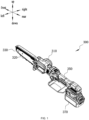
- FIG. 1 shows a chainsaw 300 as an example in the present application.
- the chainsaw 300 includes a body housing 310, a guide plate 320, a chain 330, and an electric motor 340.
- FIG. 1 defines the directions of the front side, the rear side, the upper side, the lower side, the left side, and the right side in the present application.
- the body housing 310 has a front part 3111, a rear part 3112, and an intermediate part 3113 between the front part 3111 and the rear part 3112, and an accommodation space is formed in the body housing 310.
- the guide plate 320 extends forward from the front part 3111 of the body housing 310, part of the rear end of the guide plate 320 is located inside the front part 3111 of the body housing 310, and most of the rest of the guide plate 320 extends out of the front part 3111 of the body housing 310.
- the guide plate 320 supports the chain 330 around the outer periphery of the guide plate 320, and the chain 330 is a functional piece of the chainsaw 300.
- the chainsaw 300 further includes a protective cover 3121 detachably connected to the front part 3111 of the body housing 310.
- the protective cover 3121 accommodates part of the guide plate 320 and the chain 330 and protects the chain 330 and the user.
- the electric motor 340 is accommodated in the intermediate part 3113 of the body housing 310.
- the body housing 310 may include a left body housing 3114 and a right body housing 3115 that can be joined together, and the electric motor 340 may be accommodated in the intermediate part 3113 of the right body housing.
- the chain 330 may be driven directly or indirectly through a transmission assembly so that the chain 330 moves around the guide plate 320 to perform the cutting operation.
- the motor axis may be basically perpendicular to a first plane 3202 where the guide plate 320 is located.
- the electric motor 340 is a brushless direct current (DC) electric motor 340 so that the dimension of the electric motor 340 is reduced while the performance of the electric motor 340 is maintained.
- DC direct current
- the body length L3 is defined as the distance between the frontmost side of the front part 3111 of the body housing 310 and the rearmost side of the rear part 3112 of the body housing 310.
- the ratio of the output power of the chainsaw 300 to the body length L3 may be greater than or equal to 1.5 W/mm and less than or equal to 3.5 W/mm.
- the output power of the chainsaw may be the output power of the electric motor 340, the rated power of the electric motor 340, or the power of an output shaft driving the chain 330 to move.
- the ratio of the output power of the chainsaw 300 to the body length L3 may be greater than or equal to 2 W/mm and less than or equal to 3 W/mm.
- the chainsaw 300 further includes a handle 350, an adjustment device 360, and a power supply device 370.
- the handle 350 is used for the user to hold and has an upper part 3511 and a lower part 3512, and an accommodation space is formed in the handle 350.
- the front end of the upper part 3511 of the handle forms a front end 3513 of the handle
- the rear end of the upper part 3511 of the handle is connected to the lower part 3512 of the handle
- the rear end of the upper part 3511 of the handle and the rear end of the lower part 3512 of the handle together form a rear end 3514 of the handle.
- the handle 350 is located on the rear side of the body housing 310.
- the front end 3513 of the handle is close to the rear part 3112 of the body housing 310, and the rear end 3514 of the handle is away from the body housing 310.
- a handle grip 3516 actually held by the user is between the front end 3513 and the rear end 3514 of the handle.
- the cross section of the handle grip 3516 may be quasi-circular or quasi-rectangular, and the centerline 3501 of the handle passes through the handle grip 3516.
- the centerline 3501 of the handle 350 is basically parallel to the centerline 3201 of the guide plate 320 to provide a more stable center of gravity of the telescopic chainsaw.
- the centerline 3501 of the handle and the centerline 3201 of the guide plate may coincide and are the same straight line to further stabilize the center of gravity.
- the centerline 3501 of the handle may be parallel to the centerline 3201 of the guide plate, and the centerline 3501 of the handle is located above or below the centerline 3201 of the guide plate.
- the body length L3 is defined as the distance between the frontmost side of the front part 3111 of the body housing 310 and the rearmost side of the rear part 3112 of the body housing 310
- the handle length L4 is defined as the distance between the front end surface 3513 of the handle and the rear end surface 3514 of the handle.
- the ratio of the body length L3 to the handle length L4 may be greater than or equal to 0.3 and less than or equal to 0.8. In other examples, the ratio of the body length L3 to the handle length L4 may be greater than or equal to 0.4 and less than or equal to 0.7.
- the adjustment device 360 causes the body housing 310 and the handle 350 to move relative to each other in the telescopic direction of the adjustment device 360.
- the adjustment device 360 has the retracted state and the extended state and may further include one or more semi-extended states between the retracted state and the extended state.
- the length of the chainsaw 300 in the retracted state is shorter, the length of the chainsaw 300 in the extended state or the semi-extended state is longer, and the length of the chainsaw 300 in the extended state is greater than the length of the chainsaw 300 in the semi-extended state.
- the adjustment device 360 may be implemented by multiple connecting rods sleeved in sequence and a locking assembly, and the specific structure is described in detail below. As shown in FIGS.
- the adjustment device 360 when the adjustment device 360 is in the retracted state, the front end surface 3513 of the handle abuts against the rear part 3112 of the body housing 310; and the adjustment device 360 may be entirely accommodated in the handle 350, or the adjustment device 360 may be partially accommodated in the handle 350 and partially accommodated in the body housing 310. As shown in FIGS.
- a first switch 352 for the user to operate is disposed on the handle 350.
- the first switch 352 may be located near the front end surface 3513 of the handle.
- the first switch 352 may be used for controlling the starting or stopping of the electric motor 340 and may also be used for controlling the rotational speed of the electric motor 340.
- the first switch may be a trigger switch 352.
- the trigger switch 352 may be located near the front end 3513 of the handle and may rotate around the shaft relative to the handle 350.
- the torque from the first switch 352 to the frontmost side of the chain 330 is less than or equal to 2.6 N ⁇ m.
- the first switch 352 may be a toggle switch 52 that is toggled along the front and rear direction or the left and right direction.
- the power supply device 370 can supply power to at least the electric motor 340 so that the electric motor 340 can drive the chain 330 to move around the guide plate 320.
- the power supply device 370 is a battery pack 370, and the power supply voltage of the battery pack 370 is greater than or equal to 12 V and less than or equal to 60 V.
- the power supply device 370 is not limited to the battery pack, and the chainsaw 300 may be powered in other forms.
- power supply may be achieved using AC power in conjunction with related circuits such as the transformer circuit, the rectifier circuit, and the voltage regulator circuit or the power adapter. As shown in FIGS.
- the power supply device 370 is located below the centerline 3501 of the handle 350 and is connected to the rear end 3514 of the handle.
- the lower part 3512 of the handle is formed with or connected to a coupling portion 3515.
- a battery pack 70 is detachably connected to the coupling portion 3515 along the direction of a second straight line 701.
- the battery pack 70 may be inserted into the coupling portion 3515 or pulled out from the coupling portion 3515 along the direction of the second straight line 701.
- the second straight line 701 is basically parallel to the centerline 3501 of the handle.
- the plane where the battery pack 70 is located may be perpendicular to the first plane 3202 where the guide plate 320 is located. In other cases, the second straight line 701 may be at a certain angle to the centerline 3501 of the handle.
- the total weight of the chainsaw 300 to which the power supply device 370 is not mounted is less than or equal to 2.5 kg. In other examples, the total weight of the chainsaw 300 to which the power supply device 370 is not mounted is less than or equal to 2 kg.
- the chainsaw 300 further includes a circuit board assembly 380 for controlling the power supply status of the power supply device 370 and the operating status of the electric motor 340.
- the circuit board assembly 380 is disposed in the lower part 3512 of the handle, located below the centerline 3501 of the handle, and supported by the handle 350.
- the circuit board centerline 3801 of the circuit board assembly 380 may be parallel to the centerline 3501 of the handle.
- a second plane 3802 where the circuit board assembly 380 is located may be entirely below the centerline 3501 of the handle and may be perpendicular to the first plane 3202 where the guide plate 320 is located.
- the chainsaw 300 further includes a fixed wire 381 and a movable wire 382.
- the fixed wire 381 may electrically connect the circuit board assembly 380 to the first switch 352, and the position of the fixed wire 381 may be fixed and may be a conventional circuit line. As shown in FIG. 6 , the fixed wire 381 may start from the circuit board assembly 380 in the lower part 3512 of the handle, pass through the handle 350 along a wire groove 3519 on the lower inner wall of the upper part 3511 of the handle, and reach the first switch 352 near the front end 3513 of the handle.
- the movable wire 382 may electrically connect the power supply device 370 to the electric motor 340.
- the movable wire 382 may be a spring wire 382 that is telescopic with the adjustment device 360 without affecting the power supply stability. As shown in FIG. 6 , the spring wire 382 is inserted through the rear end 3514 of the handle and the adjustment device 360. In some examples, when the adjustment device 360 is in the retracted state, the spring wire 382 may be in a pre-stretched state so that the service life of the spring wire 382 can be extended.
- the lower part 3512 of the handle is further provided with a heat dissipation port 383 on the housing close to the circuit board assembly 380.
- the heat dissipation port 383 can physically dissipate heat for the circuit board assembly 380.
- the chainsaw 300 further includes a fan, the fan may be mounted on the motor shaft and rotate with the motor shaft, the adjustment device 360 is designed to be in a highly airtight state, the heat dissipation port 383 may be an airflow inlet, and the cooling airflow generated by the fan may flow through the circuit board assembly 380, the adjustment device 360, and the electric motor 340 so that the heat dissipation performance of the telescopic chainsaw can be improved.
- a second switch 353 for the user to operate is further disposed on the handle.
- the second switch 353 can lock the electric motor 340 to remain in the starting state or the stopping state.
- the second switch 353 may be disposed on the upper side of the first switch 352 along the up and down direction, and the second switch 353 in the handle 350 may be located between the first switch 352 and a telescopic rod assembly 361; however, the second switch 353 located between the first switch 352 and the telescopic rod assembly 361 causes the outer diameter D of the handle 350 to increase, affecting the user's feeling of holding the handle 350. As shown in FIG.
- the second switch 353 may be disposed on the front side of the first switch 352 along the front and rear direction, and the second switch 353 in the handle 350 may be located on the front side of the first switch 352, on the lower side of the telescopic rod assembly 361, and near the front end 3513 of the handle, thereby not causing an increase in the outer diameter of the handle 350 and improving the user's feeling of holding the handle 350.
- the second switch 353 further has an inclined surface at the position of the thumb of the user when the user holds the chainsaw 300 so that the user can rest the thumb on the second switch 353 comfortably.
- the chainsaw 300 further includes a support assembly 390 for enabling the chainsaw 300 to which the power supply device 370 is mounted or not to stand horizontally. That is, when the chainsaw 300 is placed horizontally, the support assembly 390 can support the chainsaw 300 and enable the chainsaw 300 to keep balance and stability. At this time, the centerline 3201 of the guide plate of the chainsaw 300 remains basically parallel to the horizontal plane or at an unchanged included angle to the horizontal plane.
- the support assembly 390 may include at least a first support member 391 and a second support member 392, where the first support member 391 is in front and the second support member 392 is in the rear.
- the support provided by the first support member 391 or the second support member 392 when the chainsaw 300 stands horizontally may be any one of point support, line support, or surface support or any combination thereof.
- the chainsaw 300 to which the power supply device 370 is mounted or not is supported by the first support member 391 and the second support member 392 to stand horizontally.
- the chainsaw 300 to which the power supply device 370 is not mounted is supported by the first support member 391 and the second support member 392 to stand horizontally, and the chainsaw 300 to which the power supply device 370 is mounted is supported by the first support member 391 and the power supply device 370 mounted on the rear part of the chainsaw 300 to stand horizontally. As shown in FIGS.
- the first support member 391 is connected to the body housing 310 or is a part of the body housing 310.
- the first support member 391 may be a triangular support shown in the figure.
- the second support member 392 is connected to the handle 350.
- the second support member 392 may be a rectangular handguard shown in the figure.
- the chainsaw 300 further includes a protective part below the grip 3516 of the handle 350, the front and rear ends of the protective part are connected to the handle 350, and the protective part and the handle 350 form a through hole 3502 for the user to pass through so that in unexpected cases, for example, the chain 330 falls off the guide plate 320 or the chain 330 is broken, the path of the chain 330 hitting the human hand is blocked, thereby protecting the user and preventing the unsupported chain 330 from cutting the human hand.
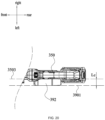
- the protective part and the handle 350 are integrally formed. As shown in FIGS. 8 and 20 , in this example, the protective part is a handle baffle, that is, a rectangular handguard 92 that has the functions of a support member and a protective part.
- the distance Lb between the frontmost side of the first switch 352 and the rear edge of the through hole 3502 is greater than or equal to 100 mm.
- the frontmost side of the first switch 352 is the frontmost end of the intersecting line of the first switch 352 and the handle 350 in the projection along the left and right direction
- the rear edge of the through hole 3502 is the rearmost end that the fingers can reach in the through hole 3502 when the user holds the handle 350 with four fingers.
- the maximum value of the distance Lc between the outer edge 3901 of a protective part 392 on the same side as the guide plate 320 and the outer edge 3503 of the handle 350 on the same side as the guide plate 320 in the left and right direction is greater than or equal to 30 mm.
- the outer edge 3503 of the handle 350 on the same side as the guide plate 320 may be the outer edge 3503 of the grip 3516 of the handle 350.
- the distance La between the rearmost side of the chain 330 exposed outside the body housing 310 and the frontmost side of the first switch 352 in the front and rear direction at least in some states during the telescopic process of the adjustment device 360 is greater than or equal to 125 mm. In some examples, it is not excluded that La is less than 125 mm in some states.
- the rearmost side of the chain 330 exposed outside the body housing 310 is the rearmost end of the intersecting line of the chain 330 and the body housing 310 in the projection along the left and right direction.
- FIGS. 12 to 17 show the adjustment device 360 in the chainsaw 300 shown in FIGS. 1 and 3 .
- the adjustment device 360 includes the telescopic rod assembly 361, where the telescopic rod assembly 361 is telescopic to at least a first state or a second state along the direction of a first straight line 3101.
- the first straight line 3101 is basically parallel to the centerline 3201 of the guide plate, that is, the first straight line 3101 is basically parallel to the centerline 3201 of the guide plate and the centerline 3501 of the handle.
- the telescopic rod assembly 361 is telescopic along the direction of the centerline 3201 of the guide plate or the centerline 3501 of the handle.
- the first straight line 3101, the centerline 3201 of the guide plate, and the centerline 3501 of the handle coincide and are the same straight line.
- the telescopic rod assembly 361 is in the first state, the adjustment device 360 is in the retracted state, the length of the chainsaw 300 at this time is defined as the first length L1 of the chainsaw 300, and the first length L1 is the minimum length of the telescopic chainsaw 300.
- the telescopic rod assembly 361 is in the second state, the adjustment device 360 is in the extended state, the length of the chainsaw 300 at this time is defined as the second length L2 of the chainsaw 300, and the second length L2 is the maximum length of the telescopic chainsaw 300.
- the telescopic rod assembly 361 is in other intermediate states between the first state and the second state, and the adjustment device 360 is in the semi-extended state. At this time, the length of the chainsaw 300 is between the first length L1 and the second length L2.
- the ratio of the second length L2 to the first length L1 of the chainsaw 300 may be greater than or equal to 1.4 and less than or equal to 2.8. In other examples, the ratio of the second length L2 to the first length L1 of the chainsaw 300 may be greater than or equal to 1.6 and less than or equal to 2.6. In other examples, the first length L1 of the chainsaw 300 is less than or equal to 550 mm, and the second length L2 of the chainsaw 300 is greater than or equal to 800 mm.
- the telescopic rod assembly 361 when the telescopic rod assembly 361 is in the first state, the telescopic rod assembly 361 is retracted and accommodated in the handle 350. Viewed from top to bottom at the rear end 3514 of the handle, the housing of the upper part 3511 of the handle, the telescopic rod assembly 361, the housing of the lower part 3512 of the handle, and the power supply device 370 exist in sequence. The projection of the power supply device 370 and the projection of the telescopic rod assembly 361 on a projection plane perpendicular to the first plane 3202 where the guide plate 320 is located at least partially coincide.
- the housing of the upper part 3511 of the handle, the telescopic rod assembly 361, the circuit board assembly 380, the housing of the lower part 3512 of the handle, and the power supply device 370 exist in sequence.
- the center of gravity of the chainsaw 300 to which the power supply device 370 is mounted is located at the handle grip 3516, which is at the purlicue in the axial direction of the handle when the user holds the handle, and the distance between the center of gravity of the chainsaw 300 and the centerline 3501 of the handle in the radial direction of the handle is less than or equal to 10 mm.
- the housing of the upper part 3511 of the handle, the circuit board assembly 380, the housing of the lower part 3512 of the handle, and the power supply device 370 exist in sequence, or the housing of the upper part 3511 of the handle, part of the rear end of the telescopic rod assembly 361, the circuit board assembly 380, the housing of the lower part 3512 of the handle, and the power supply device 370 exist in sequence.
- the center of gravity of the chainsaw 300 to which the power supply device 370 is mounted is located between the center of the handle 350 and the center of the guide plate 320.
- the telescopic rod assembly 361 may be formed by multiple connecting rods sleeved in sequence.
- the telescopic rod assembly 361 includes at least a first connecting rod 3611 and a second connecting rod 3612.
- the first connecting rod 3611 is closer to the handle 350 when the adjustment device 360 is in the extended state and is slidably connected to the handle 350.
- the second connecting rod 3612 is closer to the body housing 310 when the adjustment device 360 is in the extended state, and the front end of the second connecting rod 3612 is fixedly connected to the rear part of the body housing 310.
- the first connecting rod 3611 and the second connecting rod 3612 may be made of aluminum alloys, magnesium alloys, or carbon fiber materials to improve the operating feeling of the telescopic chainsaw 300 without affecting the performance of the telescopic chainsaw 300.
- first connecting rod 3611 and the second connecting rod 3612 may be flat tubes or square tubes, thereby enhancing the anti-rotation capability of the telescopic rod assembly 361, keeping the stability of the first connecting rod 3611 and the second connecting rod 3612 in the handle 350, and prevent the rotation of the first connecting rod 3611 and the second connecting rod 3612.
- a bushing 364 is disposed at the rear end of the first connecting rod 3611, and the bushing 364 is clamped with the rear end 3514 of the handle so that the first connecting rod 3611 remains stable in the handle 350; guide ribs 3518 parallel to the centerline 3501 of the handle are disposed on the inner wall of the handle 350, and the bushing 364 at the rear end of the first connecting rod 3611 and/or the outer wall of the first connecting rod 3611 may mate with the guide ribs 3518 so that the first connecting rod 3611 is telescopic along the direction parallel to the centerline 3501 of the handle, and the stability of the first connecting rod 3611 during the telescopic process is ensured; the bushing 364 may abut against the housing at the front end 3513 of the handle when the telescopic rod assembly 361 is in the second state, thereby preventing the first connecting rod 3611 from being disengaged from the handle 350.
- a bushing is disposed at the rear end of the second connecting rod 3612, and the bushing is clamped with the inner wall of the first connecting rod 3611 so that the second connecting rod 3612 remains stable in the first connecting rod 3611; and when the telescopic rod assembly 361 is in the second state, the bushing abuts against a second locking assembly 363 described below, thereby preventing the second connecting rod 3612 from being disengaged from the first connecting rod 3611.
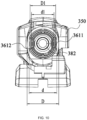
- the outer diameter D1 of the first connecting rod 3611 is less than the inner diameter d of the handle, and the outer diameter D2 of the second connecting rod 3612 is less than the inner diameter d1 of the first connecting rod 3611.
- the telescopic rod assembly 361 includes the first connecting rod 3611 and the second connecting rod 3612.
- the telescopic rod assembly 361 may include the first connecting rod 3611, the second connecting rod 3612, and at least one intermediate connecting rod.
- the ratio of the outer diameter D of the handle 350 to the outer diameter D1 of the first connecting rod 3611 may be less than or equal to 1.5, less than or equal to 1.4, or less than or equal to 1.3. In other examples, to improve the operating feel of the telescopic chainsaw 300, the ratio of the outer diameter D1 of the first connecting rod 3611 to the outer diameter D2 of the second connecting rod 3612 may be less than or equal to 1.5, less than or equal to 1.4, or less than or equal to 1.3.
- the outer diameter D of the handle 350 is greater than or equal to 35 mm and less than or equal to 40 mm, and the outer diameter D1 of the first connecting rod 3611 is greater than or equal to 25 mm and less than or equal to 30 mm.
- the adjustment device 360 further includes a first locking assembly 362 and a second locking assembly 363.
- the first locking assembly 362 is used for locking the handle 350, the first connecting rod 3611, the second connecting rod 3612, and the body housing 310 when the telescopic rod assembly 361 is in the first state so that in the first state, the first connecting rod 3611 and the second connecting rod 3612 remains in the state in which the first connecting rod 3611 and the second connecting rod 3612 are retracted and accommodated in the handle 350 and the front end 3513 of the handle closely abuts against the rear part 3112 of the body housing 310.
- the first locking assembly 362 is further used for locking the handle 350 and the first connecting rod 3611 when the telescopic rod assembly 361 is in the second state so that in the second state, the first connecting rod 3611 remains extended out of the front end 3513 of the handle.
- the second locking assembly 363 is used for locking the first connecting rod 3611 and the second connecting rod 3612 when the telescopic rod assembly 361 is in the second state so that in the second state, the second connecting rod 3612 remains extended out of the front end 3513 of the handle.
- the first locking assembly 362 is connected to the inner wall of the handle 350.
- the first locking assembly 362 includes a first protective plate 3621 fixedly connected to the inner wall of the handle 350, a first seesaw 3623 rotatably connected to the first protective plate 3621 through a first rotary shaft 3622, and a reset torsion spring 3624 sleeved on the first rotary shaft 3622 and connected to the first seesaw 3623.
- the front end of the first connecting rod 3611 is provided with a first locking hole 3611a
- the front end of the second connecting rod 3612 is provided with a second locking hole 3612a.
- the first locking hole 3611a is aligned with the second locking hole 3612a, and one end of the first seesaw 3623 is inserted through the first locking hole 3611a and the second locking hole 3612a so that the positions of the first connecting rod 3611 and the second connecting rod 3612 are locked. Further, the rear end of the first connecting rod 3611 is provided with a third locking hole 3611b.
- the first seesaw 3623 points to the center of the cross section of the handle grip 3516 when inserted into the locking hole.
- the second locking assembly 363 is connected to the outer wall of the first connecting rod 3611.
- the second locking assembly 363 includes a second protective plate 3631 fixedly connected to the outer wall of the first connecting rod 3611, a second seesaw 3633 rotatably connected to the second protective plate 3631 through a second rotary shaft 3632, and a resistance spring 3634 sandwiched between the second protective plate 3631 and the second seesaw 3633.
- the front end of the first connecting rod 3611 is provided with a fifth locking hole 3611c
- the rear end of the second connecting rod 3612 is provided with a fourth locking hole 3612b.
- the second seesaw 3633 When the telescopic rod assembly 361 is in the second state, one end of the second seesaw 3633 is inserted through the fourth locking hole 3612b and the fifth locking hole 3611c so that the positions of the first connecting rod 3611 and the second connecting rod 3612 are locked.
- the second seesaw 3633 points to the center of the cross section of the handle grip 3516 when inserted into the locking hole.
- the second protective plate 3631 may be annular and form a closed space on the outer wall of the first connecting rod 3611. The closed space accommodates the second seesaw 3633, the resistance spring 3634, and the like, thereby achieving a dust-proof effect and avoiding interference from branch debris during the cutting operation.
- the third straight line where the first locking hole 3611a, the second locking hole 3612a, and the third locking hole 3611b are located does not coincide with the fourth straight line where the fourth locking hole 3612b and the fifth locking hole 3611c are located.
- the first locking hole 3611a, the second locking hole 3612a, and the third locking hole 3611b may be disposed on the left inner wall or the right inner wall of the first connecting rod 3611 and the second connecting rod 3612
- the fourth locking hole 3612b and the fifth locking hole 3611c may be disposed on the upper inner wall or the lower inner wall of the first connecting rod 3611 and the second connecting rod 3612.
- the first locking hole 3611a, the second locking hole 3612a, and the third locking hole 3611b may be disposed on the upper inner wall or the lower inner wall of the first connecting rod 3611 and the second connecting rod 3612, and the fourth locking hole 3612b and the fifth locking hole 3611c may be disposed on the left inner wall or the right inner wall of the first connecting rod 3611 and the second connecting rod 3612.
- first seesaw 3623 and the second seesaw 3633 may be square seesaws, and the corresponding locking holes are square locking holes so that the locking between the seesaws and the locking holes is more stable.
- An adjustment switch 354 for the user to operate is disposed on the handle 350.
- the adjustment switch 354 may be disposed at the front end 3513 of the handle and near the handle grip 3516.
- the adjustment switch 354 is used for enabling or disabling the first locking assembly 362.
- the adjustment switch 354 may include a button 354. When the button 354 is triggered, the pressure is applied to the non-insertion end of the first seesaw 3623 so that the first seesaw 3623 rotates around the shaft, and the insertion end of the first seesaw 3623 is disengaged from the locking hole.
- a limiting block 3517 is disposed on the inner wall of the handle 350.
- the limiting block 3517 may be disposed near the front end surface 3513 of the handle to enable or disable the second locking assembly 363. Specifically, when the limiting block 3517 is triggered, the limiting block 3517 may abut against the second seesaw 3633 and compress the resistance spring 3634 so that the second seesaw 3633 rotates around the shaft, and the insertion end of the second seesaw 3633 is disengaged from the locking hole.
- the following first describes the extension process of the chainsaw 300 when the telescopic rod assembly 361 changes from the first state to the second state.
- the telescopic rod assembly 361 is currently in the first state, and the insertion end of the first seesaw 3623 is inserted through the first locking hole 3611a and the second locking hole 3612a.
- the button 54 to apply pressure to the non-insertion end of the first seesaw 3623, the first seesaw 3623 rotates around the first rotary shaft 3622, and the insertion end of the first seesaw 3623 is disengaged from the first locking hole 3611a and the second locking hole 3612a.
- the limiting block 3517 is set in a triggered state when the telescopic rod assembly 361 is in the first state, that is, the limiting block 3517 in the first state abuts against the second seesaw 3633 and compresses the resistance spring 3634, and the insertion end of the second seesaw 3633 is not inserted into the fifth locking hole 3611c, then after the insertion end of the first seesaw 3623 is disengaged from the first locking hole 3611a and the second locking hole 3612a, the user can directly pull out the first connecting rod 3611 and the second connecting rod 3612, and whether the connecting rod extends out of the handle first is the first connecting rod 3611 or the second connecting rod 3612 is determined by the friction between the handle and the first connecting rod 3611 and the friction between the first connecting rod 3611 and the second connecting rod 3612.
- the second seesaw 3633 abuts against the limiting block 3517 or the outer wall of the second connecting rod 3612 and compresses the resistance spring 3634, and the second seesaw 3633 remains uninserted into the fifth locking hole 3611c or inserted into the fifth locking hole 3611c but not into the fourth locking hole 3612b until the first connecting rod 3611 and the second connecting rod 3612 fully extend out of the handle 350; the second seesaw 3633 moves to the fourth locking hole 3612b and then is driven by the resistance spring 3634 to be inserted through the fourth locking hole 3612b and the fifth locking hole 3611c; and the first seesaw 3623 moves to the third locking hole 3611b and then is driven by the reset torsion spring 3624 to be inserted through the third locking hole 3611b, and the telescopic rod assembly 361 reaches the second state.
- the limiting block 3517 is set in a non-triggered state when the telescopic rod assembly 361 is in the first state, that is, the limiting block 3517 in the first state does not abut against the second seesaw 3633 or compress the resistance spring 3634, and the insertion end of the second seesaw 3633 is inserted into the fifth locking hole 3611c, then after the insertion end of the first seesaw 3623 is disengaged from the first locking hole 3611a and the second locking hole 3612a, the user can pull out the first connecting rod 3611 or the second connecting rod 3612.
- the insertion end of the second seesaw 3633 is first disengaged from the fifth locking hole 3611c, the first connecting rod 3611 extends out of the handle, the second seesaw 3633 abuts against the outer wall of the second connecting rod 3612 and compresses the resistance spring 3634, and the second seesaw 3633 remains inserted into the fifth locking hole 3611c but not into the fourth locking hole 3612b until the first connecting rod 3611 and the second connecting rod 3612 fully extend out of the handle 350; the second seesaw 3633 moves to the fourth locking hole 3612b and then is driven by the resistance spring 3634 to be inserted through the fourth locking hole 3612b and the fifth locking hole 3611c; and the first seesaw 3623 moves to the third locking hole 3611b and then is driven by the reset torsion spring 3624 to be inserted through the third locking hole 3611b, and the telescopic rod assembly 361 reaches the second state
- the limiting block 3517 limits the extension of the first connecting rod 3611, and the second seesaw 3633 remains inserted into the fifth locking hole 3611c but not into the fourth locking hole 3612b until the second seesaw 3633 moves to the fourth locking hole 3612b and then is inserted through the fourth locking hole 3612b and the fifth locking hole 3611c; before the first seesaw 3623 is inserted into the first locking hole 3611a and the telescopic rod assembly 361 can reach the second state, a third state is reached in which the second connecting rod 3612 extends out of the handle 350 and the first connecting rod 3611 is retracted and accommodated in the handle 350, where the third state is the semi-extended state of the adjustment device 360; and then the user may pull out the first connecting rod 3611.
- the second connecting rod 3612 extends out of the handle 350 and the first connecting rod 3611 is retracted and accommodated in the handle 350, where the third state is the semi-extended state of the adjustment device 360; and then the user may pull out the first connecting rod 3611.
- the following describes the retraction process of the chainsaw 300 when the telescopic rod assembly 361 changes from the second state to the first state.
- the telescopic rod assembly 361 After the user presses the button 354 to apply pressure to the non-insertion end of the first seesaw 3623, the first seesaw 3623 rotates around the shaft, the insertion end of the first seesaw 3623 is disengaged from the third locking hole 3611b, and the first connecting rod 3611 can first retract into the handle 350 until the first seesaw 3623 moves to the first locking hole 3611a; and then the limiting block 3517 on the inner wall of the handle 350 enters the triggered state, and the limiting block 3517 abuts against the second seesaw 3633 and compresses the resistance spring 3634 so that the insertion end of the second seesaw 3633 is disengaged from the fourth locking hole 3612b and the fifth locking hole 3611c, and the second connecting rod 3612 can retract into the handle 350 until the first seesaw 3623 moves to the second locking hole 3612a and is inserted through the first locking hole 3611a and the second locking hole 3612a. In this manner, the telescopic rod assembly 361 reaches the first state
Landscapes
- Engineering & Computer Science (AREA)
- Mechanical Engineering (AREA)
- Life Sciences & Earth Sciences (AREA)
- Wood Science & Technology (AREA)
- Forests & Forestry (AREA)
- Sawing (AREA)
Abstract
Description
- The present application relates to an electric tool, for example, a chain saw.
- A chainsaw, also known as a hedge trimmer, is often used for pruning branches or forest trees. The chainsaw is generally a portable small or medium-sized chainsaw. Currently, the portable small or medium-sized chainsaw has a relatively low cutting height and cannot satisfy a working condition in which an object to be cut is slightly higher. A pole saw can satisfy high-position cutting, but cannot satisfy the convenience, lightweight, and flexibility of the portable small or medium-sized chainsaw. In addition to the chainsaw, other handheld power tools, such as electric scissors, a mower, and a handheld circular saw, also face the preceding situation. For portable handheld power tools, the user expects the tools to be compact and lightweight while satisfying the requirements of different pruning heights.
- A chainsaw includes a body housing having a front part, a rear part, and an intermediate part between the front part and the rear part; an electric motor accommodated in the intermediate part of the body housing; a guide plate extending forward from the front part of the body housing; a chain disposed around the guide plate; a handle for a user to hold; a power supply device supplying power to at least the electric motor; and an adjustment device, where the body housing and the handle move relatively through the adjustment device along the extension direction of the adjustment device. The adjustment device includes a telescopic rod assembly having at least a first state and a second state. The length of the telescopic rod assembly in the second state along the front and rear direction is greater than the length of the telescopic rod assembly in the first state along the front and rear direction. In the second state, the center of gravity of the chainsaw is located between the center of the guide plate and the center of the handle.
- In an example, the handle has a grip; and in the first state, the center of gravity of the chainsaw is located in the grip.
- In an example, the centerline of the handle is basically parallel to the centerline of the guide plate.
- In an example, the centerline of the handle is collinear with the centerline of the guide plate.
- In an example, the telescopic rod assembly is telescopic along the direction of a first straight line, and the first straight line is basically parallel to the centerline of the guide plate.
- In an example, the handle has an upper part and a lower part, a coupling portion is formed on or connected to the lower part of the handle, the power supply device is detachably connected to the coupling portion along the direction of a second straight line, and the second straight line is basically parallel to the centerline of the handle.
- In an example, when the telescopic rod assembly is in the first state, the projection of the power supply device and the projection of the telescopic rod assembly on a projection plane perpendicular to a first plane where the guide plate is located at least partially coincide.
- In an example, a bushing is disposed at the rear end of the telescopic rod assembly, guide ribs parallel to the centerline of the handle are disposed in the handle, and the bushing and the guide ribs mate with each other to guide the telescopic rod assembly to be telescopic along the direction of the first straight line.
- In an example, the handle has an upper part and a lower part, and the chainsaw further includes a circuit board assembly disposed within the lower part of the handle.
- In an example, when the telescopic rod assembly is in the first state, a second plane where the circuit board assembly is located is below the first straight line, and the projection of the circuit board assembly and the projection of the telescopic rod assembly on a projection plane perpendicular to the first plane where the guide plate is located at least partially coincide.
- In an example, the chainsaw further includes a movable wire, a fixed wire, and a first switch disposed on the handle and used for starting and stopping the electric motor, where the movable wire is inserted through the handle and the adjustment device and electrically connected to the power supply device and the electric motor; and the fixed wire is disposed in the handle and electrically connected to the circuit board assembly and the first switch.
- In an example, the chainsaw further includes a first switch for starting and stopping the electric motor and a second switch for locking the starting and stopping states of the electric motor, the first switch and the second switch are disposed on the handle, and the second switch is located in front of the first switch along the direction of the centerline of the handle.
- In an example, in the first state, the adjustment device is at least partially accommodated in the handle.
- In an example, the chainsaw further includes a support assembly disposed on the body housing and/or the handle, where the support assembly is used for supporting the chainsaw and keeping balance when the chainsaw is placed horizontally.
- In an example, the chainsaw further includes a protective part below the handle, and the protective part is used for preventing a broken or fallen chain from injuring the hand of the user.
- The present application further adopts the technical solution below. A chainsaw includes a body housing having a front part, a rear part, and an intermediate part between the front part and the rear part; an electric motor accommodated in the intermediate part of the body housing; a guide plate extending forward from the front part of the body housing; a chain disposed around the guide plate; a handle for a user to hold; a power supply device supplying power to at least the electric motor; and an adjustment device, where the body housing and the handle move relatively through the adjustment device along the extension direction of the adjustment device. The centerline of the handle is basically parallel to the centerline of the guide plate, and the power supply device is located below the centerline of the handle.
- The present application further adopts the technical solution below. A chainsaw includes a body housing having a front part, a rear part, and an intermediate part between the front part and the rear part; an electric motor disposed in the intermediate part of the body housing; a guide plate extending from the front part of the body housing; a chain disposed around the guide plate; a handle used for a user to hold and having a front end surface and a rear end surface; and an adjustment device, where the body housing and the handle move relatively through the adjustment device along the extension direction of the adjustment device. The ratio of the body length of the body housing to the handle length of the handle is greater than or equal to 0.3 and less than or equal to 0.8, where the body length is the distance between the frontmost side of the front part of the body housing and the rearmost side of the rear part of the body housing, and the handle length is the distance between the front end surface of the handle and the rear end surface of the handle.
- In an example, the ratio of the body length to the handle length is greater than or equal to 0.4 and less than or equal to 0.7.
- In an example, the ratio of the output power of the chainsaw to the body length is greater than or equal to 1.5 W/mm and less than or equal to 3.5 W/mm.
- In an example, the adjustment device includes a telescopic rod assembly, where the telescopic rod assembly is telescopic to at least a first state or a second state along the direction of a first straight line.
- In an example, the ratio of the second length of the chainsaw in the second state to the first length of the chainsaw in the first state is greater than or equal to 1.4 and less than or equal to 2.8.
- In an example, the second length of the chainsaw in the second state is greater than or equal to 800 mm.
- In an example, the telescopic rod assembly includes at least a first connecting rod and a second connecting rod, where the inner diameter of the handle is greater than the outer diameter of the first connecting rod, and the inner diameter of the first connecting rod is greater than the outer diameter of the second connecting rod.
- In an example, the ratio of the outer diameter of the handle to the outer diameter of the first connecting rod is less than or equal to 1.5.
- In an example, the outer diameter of the handle is greater than or equal to 35 mm and less than or equal to 40 mm, and the outer diameter of the first connecting rod is greater than or equal to 25 mm and less than or equal to 30 mm.
- In an example, the ratio of the outer diameter of the first connecting rod to the outer diameter of the second connecting rod is less than or equal to 1.5.
- In an example, the weight of the chainsaw is less than or equal to 2.5 kg.
- The present application further adopts the technical solution below. A chainsaw includes a body housing having a front part, a rear part, and an intermediate part between the front part and the rear part; an electric motor accommodated in the intermediate part of the body housing; a guide plate extending forward from the front part of the body housing; a chain disposed around the guide plate; a handle for a user to hold; a power supply device supplying power to at least the electric motor; and an adjustment device, where the body housing and the handle move relatively through the adjustment device along the extension direction of the adjustment device. The handle has a grip. The chainsaw further includes a protective part connected to the handle and located below the grip, and when the chain is disengaged from the guide plate, the protective part blocks the path on which the chain reaches the grip.
- In an example, the adjustment device includes a telescopic rod assembly, where the telescopic rod assembly has multiple states in which the telescopic rod assembly has different lengths along the front and rear direction.
- In an example, the chainsaw further includes a first switch for starting and stopping the electric motor, and the distance between the rearmost side of the chain exposed outside the body housing and the frontmost side of the first switch along the front and rear direction in at least one state of the telescopic rod assembly is greater than or equal to 125 mm.
- In an example, the distance between the rearmost side of the chain exposed outside the body housing and the frontmost side of the first switch along the front and rear direction in at least one state of the telescopic rod assembly is less than or equal to 125 mm.
- In an example, two ends of the protective part along the front and rear direction are connected to the handle, and the protective part and the handle form a through hole for the hand of the user to pass through.
- In an example, the chainsaw further includes a first switch for starting and stopping the electric motor, and the distance between the frontmost side of the first switch and the rear edge of the through hole along the front and rear direction is greater than or equal to 100 mm.
- In an example, in the projection along the up and down direction, the maximum value of the distance between the outer edge of the protective part on the same side as the guide plate and the outer edge of the handle on the same side as the guide plate in the left and right direction is greater than or equal to 30 mm.
- In an example, the protective part supports and stabilizes the chainsaw when the chainsaw is placed horizontally.
- In an example, the power supply voltage of the power supply device is greater than or equal to 12 V and less than or equal to 60 V.
-
-
FIG. 1 is a perspective view of a chainsaw in a retracted state as an example of the present application. -
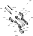
FIG. 2 is an exploded view of the chainsaw shown inFIG. 1 . -
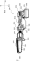
FIG. 3 is a perspective view of the chainsaw shown inFIG. 1 in an extended state. -
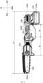
FIG. 4 is a plan view of the chainsaw shown inFIG. 1 . -
FIG. 5 is a plan view of part of the internal structure of the chainsaw shown inFIG. 1 . -
FIG. 6 is a plan view of part of the internal structure of a handle in the chainsaw shown inFIG. 1 . -
FIG. 7 is a plan view illustrating the body length and the handle length of the chainsaw shown inFIG. 1 . -
FIG. 8 is a plan view of the first length of the chainsaw shown inFIG. 1 . -
FIG. 9 is a plan view of the second length of the chainsaw shown inFIG. 3 . -
FIG. 10 is a plan view illustrating the inner and outer diameters of a handle and the inner and outer diameters of a first connecting rod of the chainsaw shown inFIG. 1 . -
FIG. 11 is a plan view illustrating the inner and outer diameters of a first connecting rod and the inner and outer diameters of a second connecting rod of the chainsaw shown inFIG. 1 . -
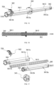
FIG. 12 is a perspective view of a telescopic rod assembly in the chainsaw shown inFIG. 1 in a first state. -
FIG. 13 is a sectional view of the telescopic rod assembly shown inFIG. 12 in the first state. -
FIG. 14 is an exploded view of the telescopic rod assembly shown inFIG. 12 in the first state. -
FIG. 15 is a perspective view of a telescopic rod assembly in the chainsaw shown in -
FIG. 3 in a second state. -
FIG. 16 is a sectional view of the telescopic rod assembly shown inFIG. 15 in the second state. -
FIG. 17 is an exploded view of the telescopic rod assembly shown inFIG. 15 in the second state. -
FIG. 18 is a perspective view of a first locking assembly in a telescopic rod assembly shown inFIG. 1 . -
FIG. 19 is an exploded view of a second locking assembly in a telescopic rod assembly shown inFIG. 3 . -
FIG. 20 is a plan view of a protective part of the chainsaw shown inFIG. 1 . - In the description of the present application, it is to be noted that orientations or position relations indicated by terms such as "center", "upper", "lower", "left", "right", "front", and "rear" are based on the drawings. These orientations or position relations are intended only to facilitate and simplify the description of the present application and not to indicate or imply that a device or element referred to must have such particular orientations or must be configured or operated in such particular orientations. Thus, these orientations or position relations are not to be construed as limiting the present application. In addition, terms such as "first" and "second" are used merely for the purpose of description or are used for distinguishing between different structures or components, and are not to be construed as indicating or implying relative importance.
-
FIG. 1 shows achainsaw 300 as an example in the present application. As shown inFIGS. 1 to 3 , thechainsaw 300 includes abody housing 310, aguide plate 320, achain 330, and anelectric motor 340. At the same time,FIG. 1 defines the directions of the front side, the rear side, the upper side, the lower side, the left side, and the right side in the present application. - The
body housing 310 has afront part 3111, arear part 3112, and anintermediate part 3113 between thefront part 3111 and therear part 3112, and an accommodation space is formed in thebody housing 310. Theguide plate 320 extends forward from thefront part 3111 of thebody housing 310, part of the rear end of theguide plate 320 is located inside thefront part 3111 of thebody housing 310, and most of the rest of theguide plate 320 extends out of thefront part 3111 of thebody housing 310. Theguide plate 320 supports thechain 330 around the outer periphery of theguide plate 320, and thechain 330 is a functional piece of thechainsaw 300. In some examples, thechainsaw 300 further includes aprotective cover 3121 detachably connected to thefront part 3111 of thebody housing 310. Theprotective cover 3121 accommodates part of theguide plate 320 and thechain 330 and protects thechain 330 and the user. - The
electric motor 340 is accommodated in theintermediate part 3113 of thebody housing 310. As shown inFIG. 2 , in this example, thebody housing 310 may include aleft body housing 3114 and aright body housing 3115 that can be joined together, and theelectric motor 340 may be accommodated in theintermediate part 3113 of the right body housing. After the motor shaft of theelectric motor 340 rotates, thechain 330 may be driven directly or indirectly through a transmission assembly so that thechain 330 moves around theguide plate 320 to perform the cutting operation. The motor axis may be basically perpendicular to afirst plane 3202 where theguide plate 320 is located. In some examples, theelectric motor 340 is a brushless direct current (DC)electric motor 340 so that the dimension of theelectric motor 340 is reduced while the performance of theelectric motor 340 is maintained. - The body length L3 is defined as the distance between the frontmost side of the
front part 3111 of thebody housing 310 and the rearmost side of therear part 3112 of thebody housing 310. In some examples, to take into account both the cutting performance and structural arrangement of the telescopic chainsaw, the ratio of the output power of thechainsaw 300 to the body length L3 may be greater than or equal to 1.5 W/mm and less than or equal to 3.5 W/mm. Specifically, the output power of the chainsaw may be the output power of theelectric motor 340, the rated power of theelectric motor 340, or the power of an output shaft driving thechain 330 to move. In other examples, the ratio of the output power of thechainsaw 300 to the body length L3 may be greater than or equal to 2 W/mm and less than or equal to 3 W/mm. - As shown in
FIGS. 1 to 3 , thechainsaw 300 further includes ahandle 350, anadjustment device 360, and apower supply device 370. - The
handle 350 is used for the user to hold and has anupper part 3511 and alower part 3512, and an accommodation space is formed in thehandle 350. The front end of theupper part 3511 of the handle forms afront end 3513 of the handle, the rear end of theupper part 3511 of the handle is connected to thelower part 3512 of the handle, and the rear end of theupper part 3511 of the handle and the rear end of thelower part 3512 of the handle together form arear end 3514 of the handle. Thehandle 350 is located on the rear side of thebody housing 310. Thefront end 3513 of the handle is close to therear part 3112 of thebody housing 310, and therear end 3514 of the handle is away from thebody housing 310. Ahandle grip 3516 actually held by the user is between thefront end 3513 and therear end 3514 of the handle. The cross section of thehandle grip 3516 may be quasi-circular or quasi-rectangular, and thecenterline 3501 of the handle passes through thehandle grip 3516. As shown inFIGS. 4 and5 , thecenterline 3501 of thehandle 350 is basically parallel to thecenterline 3201 of theguide plate 320 to provide a more stable center of gravity of the telescopic chainsaw. In this example, thecenterline 3501 of the handle and thecenterline 3201 of the guide plate may coincide and are the same straight line to further stabilize the center of gravity. In other cases, thecenterline 3501 of the handle may be parallel to thecenterline 3201 of the guide plate, and thecenterline 3501 of the handle is located above or below thecenterline 3201 of the guide plate. - As shown in
FIG. 7 , the body length L3 is defined as the distance between the frontmost side of thefront part 3111 of thebody housing 310 and the rearmost side of therear part 3112 of thebody housing 310, and the handle length L4 is defined as the distance between thefront end surface 3513 of the handle and therear end surface 3514 of the handle. In some examples, to optimize the center of gravity of the telescopic chainsaw and improve the operating feel of the telescopic chainsaw, the ratio of the body length L3 to the handle length L4 may be greater than or equal to 0.3 and less than or equal to 0.8. In other examples, the ratio of the body length L3 to the handle length L4 may be greater than or equal to 0.4 and less than or equal to 0.7. Through the change in the length of theadjustment device 360, theadjustment device 360 causes thebody housing 310 and thehandle 350 to move relative to each other in the telescopic direction of theadjustment device 360. Theadjustment device 360 has the retracted state and the extended state and may further include one or more semi-extended states between the retracted state and the extended state. The length of thechainsaw 300 in the retracted state is shorter, the length of thechainsaw 300 in the extended state or the semi-extended state is longer, and the length of thechainsaw 300 in the extended state is greater than the length of thechainsaw 300 in the semi-extended state. Theadjustment device 360 may be implemented by multiple connecting rods sleeved in sequence and a locking assembly, and the specific structure is described in detail below. As shown inFIGS. 1 ,4 , and5 , when theadjustment device 360 is in the retracted state, thefront end surface 3513 of the handle abuts against therear part 3112 of thebody housing 310; and theadjustment device 360 may be entirely accommodated in thehandle 350, or theadjustment device 360 may be partially accommodated in thehandle 350 and partially accommodated in thebody housing 310. As shown inFIGS. 3 and9 , when theadjustment device 360 is in the extended state, thefront end surface 3513 of the handle is separated from therear part 3112 of thebody housing 310, theadjustment device 360 may be located between thehandle 350 and thebody housing 310, part of the rear end of theadjustment device 360 may be located in thehandle 350, part of the front end of theadjustment device 360 may be located in therear part 3112 of thebody housing 310, and most of the rest of theadjustment device 360 extends out of thehandle 350 and thebody housing 310. - A
first switch 352 for the user to operate is disposed on thehandle 350. Thefirst switch 352 may be located near thefront end surface 3513 of the handle. Thefirst switch 352 may be used for controlling the starting or stopping of theelectric motor 340 and may also be used for controlling the rotational speed of theelectric motor 340. In this example, the first switch may be atrigger switch 352. Thetrigger switch 352 may be located near thefront end 3513 of the handle and may rotate around the shaft relative to thehandle 350. When thechainsaw 300 is equipped with thepower supply device 370, the torque from thefirst switch 352 to the frontmost side of thechain 330 is less than or equal to 2.6 N·m. In other cases, thefirst switch 352 may be a toggle switch 52 that is toggled along the front and rear direction or the left and right direction. - The
power supply device 370 can supply power to at least theelectric motor 340 so that theelectric motor 340 can drive thechain 330 to move around theguide plate 320. In this example, thepower supply device 370 is abattery pack 370, and the power supply voltage of thebattery pack 370 is greater than or equal to 12 V and less than or equal to 60 V. However, thepower supply device 370 is not limited to the battery pack, and thechainsaw 300 may be powered in other forms. In some cases, power supply may be achieved using AC power in conjunction with related circuits such as the transformer circuit, the rectifier circuit, and the voltage regulator circuit or the power adapter. As shown inFIGS. 4 and5 , thepower supply device 370 is located below thecenterline 3501 of thehandle 350 and is connected to therear end 3514 of the handle. In this example, thelower part 3512 of the handle is formed with or connected to acoupling portion 3515. A battery pack 70 is detachably connected to thecoupling portion 3515 along the direction of a second straight line 701. The battery pack 70 may be inserted into thecoupling portion 3515 or pulled out from thecoupling portion 3515 along the direction of the second straight line 701. In this example, the second straight line 701 is basically parallel to thecenterline 3501 of the handle. For example, the plane where the battery pack 70 is located may be perpendicular to thefirst plane 3202 where theguide plate 320 is located. In other cases, the second straight line 701 may be at a certain angle to thecenterline 3501 of the handle. - In some examples, the total weight of the
chainsaw 300 to which thepower supply device 370 is not mounted is less than or equal to 2.5 kg. In other examples, the total weight of thechainsaw 300 to which thepower supply device 370 is not mounted is less than or equal to 2 kg. - The
chainsaw 300 further includes acircuit board assembly 380 for controlling the power supply status of thepower supply device 370 and the operating status of theelectric motor 340. As shown inFIGS. 4 and5 , thecircuit board assembly 380 is disposed in thelower part 3512 of the handle, located below thecenterline 3501 of the handle, and supported by thehandle 350. Thecircuit board centerline 3801 of thecircuit board assembly 380 may be parallel to thecenterline 3501 of the handle. In some examples, asecond plane 3802 where thecircuit board assembly 380 is located may be entirely below thecenterline 3501 of the handle and may be perpendicular to thefirst plane 3202 where theguide plate 320 is located. - The
chainsaw 300 further includes a fixedwire 381 and amovable wire 382. The fixedwire 381 may electrically connect thecircuit board assembly 380 to thefirst switch 352, and the position of the fixedwire 381 may be fixed and may be a conventional circuit line. As shown inFIG. 6 , the fixedwire 381 may start from thecircuit board assembly 380 in thelower part 3512 of the handle, pass through thehandle 350 along awire groove 3519 on the lower inner wall of theupper part 3511 of the handle, and reach thefirst switch 352 near thefront end 3513 of the handle. Themovable wire 382 may electrically connect thepower supply device 370 to theelectric motor 340. Since theadjustment device 360 with varying lengths exists between thepower supply device 370 and theelectric motor 340, themovable wire 382 may be aspring wire 382 that is telescopic with theadjustment device 360 without affecting the power supply stability. As shown inFIG. 6 , thespring wire 382 is inserted through therear end 3514 of the handle and theadjustment device 360. In some examples, when theadjustment device 360 is in the retracted state, thespring wire 382 may be in a pre-stretched state so that the service life of thespring wire 382 can be extended. - The
lower part 3512 of the handle is further provided with aheat dissipation port 383 on the housing close to thecircuit board assembly 380. Theheat dissipation port 383 can physically dissipate heat for thecircuit board assembly 380. In other cases, thechainsaw 300 further includes a fan, the fan may be mounted on the motor shaft and rotate with the motor shaft, theadjustment device 360 is designed to be in a highly airtight state, theheat dissipation port 383 may be an airflow inlet, and the cooling airflow generated by the fan may flow through thecircuit board assembly 380, theadjustment device 360, and theelectric motor 340 so that the heat dissipation performance of the telescopic chainsaw can be improved. - A
second switch 353 for the user to operate is further disposed on the handle. Thesecond switch 353 can lock theelectric motor 340 to remain in the starting state or the stopping state. In some examples, thesecond switch 353 may be disposed on the upper side of thefirst switch 352 along the up and down direction, and thesecond switch 353 in thehandle 350 may be located between thefirst switch 352 and atelescopic rod assembly 361; however, thesecond switch 353 located between thefirst switch 352 and thetelescopic rod assembly 361 causes the outer diameter D of thehandle 350 to increase, affecting the user's feeling of holding thehandle 350. As shown inFIG. 6 , in this example, thesecond switch 353 may be disposed on the front side of thefirst switch 352 along the front and rear direction, and thesecond switch 353 in thehandle 350 may be located on the front side of thefirst switch 352, on the lower side of thetelescopic rod assembly 361, and near thefront end 3513 of the handle, thereby not causing an increase in the outer diameter of thehandle 350 and improving the user's feeling of holding thehandle 350. In other examples, thesecond switch 353 further has an inclined surface at the position of the thumb of the user when the user holds thechainsaw 300 so that the user can rest the thumb on thesecond switch 353 comfortably. - The
chainsaw 300 further includes a support assembly 390 for enabling thechainsaw 300 to which thepower supply device 370 is mounted or not to stand horizontally. That is, when thechainsaw 300 is placed horizontally, the support assembly 390 can support thechainsaw 300 and enable thechainsaw 300 to keep balance and stability. At this time, thecenterline 3201 of the guide plate of thechainsaw 300 remains basically parallel to the horizontal plane or at an unchanged included angle to the horizontal plane. In some examples, the support assembly 390 may include at least afirst support member 391 and asecond support member 392, where thefirst support member 391 is in front and thesecond support member 392 is in the rear. The support provided by thefirst support member 391 or thesecond support member 392 when thechainsaw 300 stands horizontally may be any one of point support, line support, or surface support or any combination thereof. In some examples, thechainsaw 300 to which thepower supply device 370 is mounted or not is supported by thefirst support member 391 and thesecond support member 392 to stand horizontally. In other examples, thechainsaw 300 to which thepower supply device 370 is not mounted is supported by thefirst support member 391 and thesecond support member 392 to stand horizontally, and thechainsaw 300 to which thepower supply device 370 is mounted is supported by thefirst support member 391 and thepower supply device 370 mounted on the rear part of thechainsaw 300 to stand horizontally. As shown inFIGS. 3 and4 , in some examples, thefirst support member 391 is connected to thebody housing 310 or is a part of thebody housing 310. For example, thefirst support member 391 may be a triangular support shown in the figure. Thesecond support member 392 is connected to thehandle 350. For example, thesecond support member 392 may be a rectangular handguard shown in the figure. When thechainsaw 300 to which thepower supply device 370 is not mounted is placed on a horizontal surface, thechainsaw 300 is supported by the bottom end of thefirst support member 391 and the front edge of thesecond support member 392. When thechainsaw 300 to which thepower supply device 370 is mounted is placed on a horizontal surface, thechainsaw 300 is supported by the bottom end of thefirst support member 391 and the bottom surface of thepower supply device 370. - In some examples, the
chainsaw 300 further includes a protective part below thegrip 3516 of thehandle 350, the front and rear ends of the protective part are connected to thehandle 350, and the protective part and thehandle 350 form a throughhole 3502 for the user to pass through so that in unexpected cases, for example, thechain 330 falls off theguide plate 320 or thechain 330 is broken, the path of thechain 330 hitting the human hand is blocked, thereby protecting the user and preventing theunsupported chain 330 from cutting the human hand. In some examples, the protective part and thehandle 350 are integrally formed. As shown inFIGS. 8 and20 , in this example, the protective part is a handle baffle, that is, a rectangular handguard 92 that has the functions of a support member and a protective part. In some examples, the distance Lb between the frontmost side of thefirst switch 352 and the rear edge of the throughhole 3502 is greater than or equal to 100 mm. The frontmost side of thefirst switch 352 is the frontmost end of the intersecting line of thefirst switch 352 and thehandle 350 in the projection along the left and right direction, and the rear edge of the throughhole 3502 is the rearmost end that the fingers can reach in the throughhole 3502 when the user holds thehandle 350 with four fingers. In some examples, in the projection along the up and down direction, the maximum value of the distance Lc between the outer edge 3901 of aprotective part 392 on the same side as theguide plate 320 and theouter edge 3503 of thehandle 350 on the same side as theguide plate 320 in the left and right direction is greater than or equal to 30 mm. Specifically, theouter edge 3503 of thehandle 350 on the same side as theguide plate 320 may be theouter edge 3503 of thegrip 3516 of thehandle 350. - In some examples, the distance La between the rearmost side of the
chain 330 exposed outside thebody housing 310 and the frontmost side of thefirst switch 352 in the front and rear direction at least in some states during the telescopic process of theadjustment device 360 is greater than or equal to 125 mm. In some examples, it is not excluded that La is less than 125 mm in some states. The rearmost side of thechain 330 exposed outside thebody housing 310 is the rearmost end of the intersecting line of thechain 330 and thebody housing 310 in the projection along the left and right direction. -
FIGS. 12 to 17 show theadjustment device 360 in thechainsaw 300 shown inFIGS. 1 and3 . Theadjustment device 360 includes thetelescopic rod assembly 361, where thetelescopic rod assembly 361 is telescopic to at least a first state or a second state along the direction of a firststraight line 3101. The firststraight line 3101 is basically parallel to thecenterline 3201 of the guide plate, that is, the firststraight line 3101 is basically parallel to thecenterline 3201 of the guide plate and thecenterline 3501 of the handle. Thetelescopic rod assembly 361 is telescopic along the direction of thecenterline 3201 of the guide plate or thecenterline 3501 of the handle. In some examples, the firststraight line 3101, thecenterline 3201 of the guide plate, and thecenterline 3501 of the handle coincide and are the same straight line. - As shown in
FIGS. 1 ,4 ,5 , and8 , thetelescopic rod assembly 361 is in the first state, theadjustment device 360 is in the retracted state, the length of thechainsaw 300 at this time is defined as the first length L1 of thechainsaw 300, and the first length L1 is the minimum length of thetelescopic chainsaw 300. As shown inFIGS. 3 and9 , thetelescopic rod assembly 361 is in the second state, theadjustment device 360 is in the extended state, the length of thechainsaw 300 at this time is defined as the second length L2 of thechainsaw 300, and the second length L2 is the maximum length of thetelescopic chainsaw 300. In some examples, thetelescopic rod assembly 361 is in other intermediate states between the first state and the second state, and theadjustment device 360 is in the semi-extended state. At this time, the length of thechainsaw 300 is between the first length L1 and the second length L2. - In some examples, to take into account both the telescopic function and the good center of gravity, the ratio of the second length L2 to the first length L1 of the
chainsaw 300 may be greater than or equal to 1.4 and less than or equal to 2.8. In other examples, the ratio of the second length L2 to the first length L1 of thechainsaw 300 may be greater than or equal to 1.6 and less than or equal to 2.6. In other examples, the first length L1 of thechainsaw 300 is less than or equal to 550 mm, and the second length L2 of thechainsaw 300 is greater than or equal to 800 mm. - As shown in
FIGS. 1 ,4 , and5 , when thetelescopic rod assembly 361 is in the first state, thetelescopic rod assembly 361 is retracted and accommodated in thehandle 350. Viewed from top to bottom at therear end 3514 of the handle, the housing of theupper part 3511 of the handle, thetelescopic rod assembly 361, the housing of thelower part 3512 of the handle, and thepower supply device 370 exist in sequence. The projection of thepower supply device 370 and the projection of thetelescopic rod assembly 361 on a projection plane perpendicular to thefirst plane 3202 where theguide plate 320 is located at least partially coincide. In some examples, viewed from top to bottom at therear end 3514 of the handle, the housing of theupper part 3511 of the handle, thetelescopic rod assembly 361, thecircuit board assembly 380, the housing of thelower part 3512 of the handle, and thepower supply device 370 exist in sequence. The projection of thecircuit board assembly 380 and the projection of thetelescopic rod assembly 361 on the projection plane perpendicular to thefirst plane 3202 where theguide plate 320 is located at least partially coincide. - In this example, when the
telescopic rod assembly 361 is in the first state, the center of gravity of thechainsaw 300 to which thepower supply device 370 is mounted is located at thehandle grip 3516, which is at the purlicue in the axial direction of the handle when the user holds the handle, and the distance between the center of gravity of thechainsaw 300 and thecenterline 3501 of the handle in the radial direction of the handle is less than or equal to 10 mm. - As shown in
FIGS. 3 and9 , when thetelescopic rod assembly 361 is in the second state, thetelescopic rod assembly 361 extends out of thehandle 350. Viewed from top to bottom at therear end 3514 of the handle, the housing of theupper part 3511 of the handle, the housing of thelower part 3512 of the handle, and thepower supply device 370 exist in sequence, or the housing of theupper part 3511 of the handle, part of the rear end of thetelescopic rod assembly 361, the housing of thelower part 3512 of the handle, and thepower supply device 370 exist in sequence. In some examples, viewed from top to bottom at therear end 3514 of the handle, the housing of theupper part 3511 of the handle, thecircuit board assembly 380, the housing of thelower part 3512 of the handle, and thepower supply device 370 exist in sequence, or the housing of theupper part 3511 of the handle, part of the rear end of thetelescopic rod assembly 361, thecircuit board assembly 380, the housing of thelower part 3512 of the handle, and thepower supply device 370 exist in sequence. - In this example, when the
telescopic rod assembly 361 is in the second state, the center of gravity of thechainsaw 300 to which thepower supply device 370 is mounted is located between the center of thehandle 350 and the center of theguide plate 320. - As shown in
FIGS. 12 and15 , thetelescopic rod assembly 361 may be formed by multiple connecting rods sleeved in sequence. Thetelescopic rod assembly 361 includes at least a first connectingrod 3611 and a second connectingrod 3612. The first connectingrod 3611 is closer to thehandle 350 when theadjustment device 360 is in the extended state and is slidably connected to thehandle 350. The second connectingrod 3612 is closer to thebody housing 310 when theadjustment device 360 is in the extended state, and the front end of the second connectingrod 3612 is fixedly connected to the rear part of thebody housing 310. In some examples, the first connectingrod 3611 and the second connectingrod 3612 may be made of aluminum alloys, magnesium alloys, or carbon fiber materials to improve the operating feeling of thetelescopic chainsaw 300 without affecting the performance of thetelescopic chainsaw 300. - In some examples, the first connecting
rod 3611 and the second connectingrod 3612 may be flat tubes or square tubes, thereby enhancing the anti-rotation capability of thetelescopic rod assembly 361, keeping the stability of the first connectingrod 3611 and the second connectingrod 3612 in thehandle 350, and prevent the rotation of the first connectingrod 3611 and the second connectingrod 3612. - In some examples, as shown in
FIGS. 6 ,14 , and17 , abushing 364 is disposed at the rear end of the first connectingrod 3611, and thebushing 364 is clamped with therear end 3514 of the handle so that the first connectingrod 3611 remains stable in thehandle 350; guideribs 3518 parallel to thecenterline 3501 of the handle are disposed on the inner wall of thehandle 350, and thebushing 364 at the rear end of the first connectingrod 3611 and/or the outer wall of the first connectingrod 3611 may mate with theguide ribs 3518 so that the first connectingrod 3611 is telescopic along the direction parallel to thecenterline 3501 of the handle, and the stability of the first connectingrod 3611 during the telescopic process is ensured; thebushing 364 may abut against the housing at thefront end 3513 of the handle when thetelescopic rod assembly 361 is in the second state, thereby preventing the first connectingrod 3611 from being disengaged from thehandle 350. In other examples, a bushing is disposed at the rear end of the second connectingrod 3612, and the bushing is clamped with the inner wall of the first connectingrod 3611 so that the second connectingrod 3612 remains stable in the first connectingrod 3611; and when thetelescopic rod assembly 361 is in the second state, the bushing abuts against asecond locking assembly 363 described below, thereby preventing the second connectingrod 3612 from being disengaged from the first connectingrod 3611. - As shown in
FIGS. 10 and11 , the outer diameter D1 of the first connectingrod 3611 is less than the inner diameter d of the handle, and the outer diameter D2 of the second connectingrod 3612 is less than the inner diameter d1 of the first connectingrod 3611. The following mainly describes the case where thetelescopic rod assembly 361 includes the first connectingrod 3611 and the second connectingrod 3612. In other cases, thetelescopic rod assembly 361 may include the first connectingrod 3611, the second connectingrod 3612, and at least one intermediate connecting rod. When theadjustment device 360 is in the extended state, the inner diameter of the connecting rod closer to thehandle 350 in the front and rear direction is greater than the outer diameter of the connecting rod closer to therear part 3112 of thebody housing 310. - As shown in
FIGS. 10 and11 , in some examples, to improve the operating feel of thetelescopic chainsaw 300 and reduce the handle diameter, the ratio of the outer diameter D of thehandle 350 to the outer diameter D1 of the first connectingrod 3611 may be less than or equal to 1.5, less than or equal to 1.4, or less than or equal to 1.3. In other examples, to improve the operating feel of thetelescopic chainsaw 300, the ratio of the outer diameter D1 of the first connectingrod 3611 to the outer diameter D2 of the second connectingrod 3612 may be less than or equal to 1.5, less than or equal to 1.4, or less than or equal to 1.3. In other examples, to improve the operating feel of thetelescopic chainsaw 300, the outer diameter D of thehandle 350 is greater than or equal to 35 mm and less than or equal to 40 mm, and the outer diameter D1 of the first connectingrod 3611 is greater than or equal to 25 mm and less than or equal to 30 mm. - The
adjustment device 360 further includes afirst locking assembly 362 and asecond locking assembly 363. Thefirst locking assembly 362 is used for locking thehandle 350, the first connectingrod 3611, the second connectingrod 3612, and thebody housing 310 when thetelescopic rod assembly 361 is in the first state so that in the first state, the first connectingrod 3611 and the second connectingrod 3612 remains in the state in which the first connectingrod 3611 and the second connectingrod 3612 are retracted and accommodated in thehandle 350 and thefront end 3513 of the handle closely abuts against therear part 3112 of thebody housing 310. Thefirst locking assembly 362 is further used for locking thehandle 350 and the first connectingrod 3611 when thetelescopic rod assembly 361 is in the second state so that in the second state, the first connectingrod 3611 remains extended out of thefront end 3513 of the handle. Thesecond locking assembly 363 is used for locking the first connectingrod 3611 and the second connectingrod 3612 when thetelescopic rod assembly 361 is in the second state so that in the second state, the second connectingrod 3612 remains extended out of thefront end 3513 of the handle. - As shown in
FIGS. 14 ,17 , and18 , in some examples, thefirst locking assembly 362 is connected to the inner wall of thehandle 350. In this example, thefirst locking assembly 362 includes a firstprotective plate 3621 fixedly connected to the inner wall of thehandle 350, afirst seesaw 3623 rotatably connected to the firstprotective plate 3621 through afirst rotary shaft 3622, and areset torsion spring 3624 sleeved on thefirst rotary shaft 3622 and connected to thefirst seesaw 3623. The front end of the first connectingrod 3611 is provided with afirst locking hole 3611a, and the front end of the second connectingrod 3612 is provided with asecond locking hole 3612a. When thetelescopic rod assembly 361 is in the first state, thefirst locking hole 3611a is aligned with thesecond locking hole 3612a, and one end of thefirst seesaw 3623 is inserted through thefirst locking hole 3611a and thesecond locking hole 3612a so that the positions of the first connectingrod 3611 and the second connectingrod 3612 are locked. Further, the rear end of the first connectingrod 3611 is provided with athird locking hole 3611b. When thetelescopic rod assembly 361 is in the second state, one end of thefirst seesaw 3623 is inserted into thethird locking hole 3611b so that the position of the first connectingrod 3611 is locked. In some examples, thefirst seesaw 3623 points to the center of the cross section of thehandle grip 3516 when inserted into the locking hole. - As shown in
FIGS. 14 ,17 , and19 , in some examples, thesecond locking assembly 363 is connected to the outer wall of the first connectingrod 3611. In this example, thesecond locking assembly 363 includes a secondprotective plate 3631 fixedly connected to the outer wall of the first connectingrod 3611, asecond seesaw 3633 rotatably connected to the secondprotective plate 3631 through asecond rotary shaft 3632, and aresistance spring 3634 sandwiched between the secondprotective plate 3631 and thesecond seesaw 3633. Further, the front end of the first connectingrod 3611 is provided with afifth locking hole 3611c, and the rear end of the second connectingrod 3612 is provided with afourth locking hole 3612b. When thetelescopic rod assembly 361 is in the second state, one end of thesecond seesaw 3633 is inserted through thefourth locking hole 3612b and thefifth locking hole 3611c so that the positions of the first connectingrod 3611 and the second connectingrod 3612 are locked. In some examples, thesecond seesaw 3633 points to the center of the cross section of thehandle grip 3516 when inserted into the locking hole. In some examples, the secondprotective plate 3631 may be annular and form a closed space on the outer wall of the first connectingrod 3611. The closed space accommodates thesecond seesaw 3633, theresistance spring 3634, and the like, thereby achieving a dust-proof effect and avoiding interference from branch debris during the cutting operation. - To avoid mutual interference between the
first locking assembly 362 and thesecond locking assembly 363, the third straight line where thefirst locking hole 3611a, thesecond locking hole 3612a, and thethird locking hole 3611b are located does not coincide with the fourth straight line where thefourth locking hole 3612b and thefifth locking hole 3611c are located. For example, thefirst locking hole 3611a, thesecond locking hole 3612a, and thethird locking hole 3611b may be disposed on the left inner wall or the right inner wall of the first connectingrod 3611 and the second connectingrod 3612, and thefourth locking hole 3612b and thefifth locking hole 3611c may be disposed on the upper inner wall or the lower inner wall of the first connectingrod 3611 and the second connectingrod 3612. Thefirst locking hole 3611a, thesecond locking hole 3612a, and thethird locking hole 3611b may be disposed on the upper inner wall or the lower inner wall of the first connectingrod 3611 and the second connectingrod 3612, and thefourth locking hole 3612b and thefifth locking hole 3611c may be disposed on the left inner wall or the right inner wall of the first connectingrod 3611 and the second connectingrod 3612. - In some examples, the
first seesaw 3623 and thesecond seesaw 3633 may be square seesaws, and the corresponding locking holes are square locking holes so that the locking between the seesaws and the locking holes is more stable. - An
adjustment switch 354 for the user to operate is disposed on thehandle 350. Theadjustment switch 354 may be disposed at thefront end 3513 of the handle and near thehandle grip 3516. Theadjustment switch 354 is used for enabling or disabling thefirst locking assembly 362. Specifically, theadjustment switch 354 may include abutton 354. When thebutton 354 is triggered, the pressure is applied to the non-insertion end of thefirst seesaw 3623 so that thefirst seesaw 3623 rotates around the shaft, and the insertion end of thefirst seesaw 3623 is disengaged from the locking hole. - As shown in
FIG. 6 , a limitingblock 3517 is disposed on the inner wall of thehandle 350. The limitingblock 3517 may be disposed near thefront end surface 3513 of the handle to enable or disable thesecond locking assembly 363. Specifically, when the limitingblock 3517 is triggered, the limitingblock 3517 may abut against thesecond seesaw 3633 and compress theresistance spring 3634 so that thesecond seesaw 3633 rotates around the shaft, and the insertion end of thesecond seesaw 3633 is disengaged from the locking hole. - The following first describes the extension process of the
chainsaw 300 when thetelescopic rod assembly 361 changes from the first state to the second state. - It is assumed that the
telescopic rod assembly 361 is currently in the first state, and the insertion end of thefirst seesaw 3623 is inserted through thefirst locking hole 3611a and thesecond locking hole 3612a. When the user presses the button 54 to apply pressure to the non-insertion end of thefirst seesaw 3623, thefirst seesaw 3623 rotates around thefirst rotary shaft 3622, and the insertion end of thefirst seesaw 3623 is disengaged from thefirst locking hole 3611a and thesecond locking hole 3612a. If the limitingblock 3517 is set in a triggered state when thetelescopic rod assembly 361 is in the first state, that is, the limitingblock 3517 in the first state abuts against thesecond seesaw 3633 and compresses theresistance spring 3634, and the insertion end of thesecond seesaw 3633 is not inserted into thefifth locking hole 3611c, then after the insertion end of thefirst seesaw 3623 is disengaged from thefirst locking hole 3611a and thesecond locking hole 3612a, the user can directly pull out the first connectingrod 3611 and the second connectingrod 3612, and whether the connecting rod extends out of the handle first is the first connectingrod 3611 or the second connectingrod 3612 is determined by the friction between the handle and the first connectingrod 3611 and the friction between the first connectingrod 3611 and the second connectingrod 3612. - When the first connecting rod and the second connecting rod extend out of the handle in sequence, the
second seesaw 3633 abuts against the limitingblock 3517 or the outer wall of the second connectingrod 3612 and compresses theresistance spring 3634, and thesecond seesaw 3633 remains uninserted into thefifth locking hole 3611c or inserted into thefifth locking hole 3611c but not into thefourth locking hole 3612b until the first connectingrod 3611 and the second connectingrod 3612 fully extend out of thehandle 350; thesecond seesaw 3633 moves to thefourth locking hole 3612b and then is driven by theresistance spring 3634 to be inserted through thefourth locking hole 3612b and thefifth locking hole 3611c; and thefirst seesaw 3623 moves to thethird locking hole 3611b and then is driven by thereset torsion spring 3624 to be inserted through thethird locking hole 3611b, and thetelescopic rod assembly 361 reaches the second state. - If the limiting
block 3517 is set in a non-triggered state when thetelescopic rod assembly 361 is in the first state, that is, the limitingblock 3517 in the first state does not abut against thesecond seesaw 3633 or compress theresistance spring 3634, and the insertion end of thesecond seesaw 3633 is inserted into thefifth locking hole 3611c, then after the insertion end of thefirst seesaw 3623 is disengaged from thefirst locking hole 3611a and thesecond locking hole 3612a, the user can pull out the first connectingrod 3611 or the second connectingrod 3612. - In the case where the first connecting
rod 3611 is pulled out first, the force applied by the user causes the limitingblock 3517 to be triggered, the insertion end of thesecond seesaw 3633 is first disengaged from thefifth locking hole 3611c, the first connectingrod 3611 extends out of the handle, thesecond seesaw 3633 abuts against the outer wall of the second connectingrod 3612 and compresses theresistance spring 3634, and thesecond seesaw 3633 remains inserted into thefifth locking hole 3611c but not into thefourth locking hole 3612b until the first connectingrod 3611 and the second connectingrod 3612 fully extend out of thehandle 350; thesecond seesaw 3633 moves to thefourth locking hole 3612b and then is driven by theresistance spring 3634 to be inserted through thefourth locking hole 3612b and thefifth locking hole 3611c; and thefirst seesaw 3623 moves to thethird locking hole 3611b and then is driven by thereset torsion spring 3624 to be inserted through thethird locking hole 3611b, and thetelescopic rod assembly 361 reaches the second state. - In the case where the second connecting
rod 3612 is pulled out first, the limitingblock 3517 limits the extension of the first connectingrod 3611, and thesecond seesaw 3633 remains inserted into thefifth locking hole 3611c but not into thefourth locking hole 3612b until thesecond seesaw 3633 moves to thefourth locking hole 3612b and then is inserted through thefourth locking hole 3612b and thefifth locking hole 3611c; before thefirst seesaw 3623 is inserted into thefirst locking hole 3611a and thetelescopic rod assembly 361 can reach the second state, a third state is reached in which the second connectingrod 3612 extends out of thehandle 350 and the first connectingrod 3611 is retracted and accommodated in thehandle 350, where the third state is the semi-extended state of theadjustment device 360; and then the user may pull out the first connectingrod 3611. For the subsequent specific process of reaching the second state, reference may be made to the relevant description above, and the details are not repeated here. - The following describes the retraction process of the
chainsaw 300 when thetelescopic rod assembly 361 changes from the second state to the first state. - It is assumed that the
telescopic rod assembly 361 is currently in the second state, the insertion end of thefirst seesaw 3623 is inserted into thethird locking hole 3611b, and the insertion end of thesecond seesaw 3633 is inserted through thefourth locking hole 3612b and thefifth locking hole 3611c. After the user presses thebutton 354 to apply pressure to the non-insertion end of thefirst seesaw 3623, thefirst seesaw 3623 rotates around the shaft, the insertion end of thefirst seesaw 3623 is disengaged from thethird locking hole 3611b, and the first connectingrod 3611 can first retract into thehandle 350 until thefirst seesaw 3623 moves to thefirst locking hole 3611a; and then the limitingblock 3517 on the inner wall of thehandle 350 enters the triggered state, and the limitingblock 3517 abuts against thesecond seesaw 3633 and compresses theresistance spring 3634 so that the insertion end of thesecond seesaw 3633 is disengaged from thefourth locking hole 3612b and thefifth locking hole 3611c, and the second connectingrod 3612 can retract into thehandle 350 until thefirst seesaw 3623 moves to thesecond locking hole 3612a and is inserted through thefirst locking hole 3611a and thesecond locking hole 3612a. In this manner, thetelescopic rod assembly 361 reaches the first state. - In some examples, the
adjustment device 360 may further include a greater number of locking assemblies in other forms, thetelescopic rod assembly 361 may further include an intermediate connecting rod, and the connecting rods may be provided with a greater number of locking holes. In this manner, the locking assemblies mate with the telescopic rod assembly so that the stepless adjustment of theadjustment device 360 is achieved, and the length of theadjustment device 360 can be locked at any length value within a length range during the adjustment process.
Claims (15)
- A chainsaw (300), comprising:a body housing (310) having a front part (3111), a rear part (3112), and an intermediate part (3113) between the front part and the rear part;an electric motor (340) accommodated in the intermediate part of the body housing;a guide plate (320) extending forward from the front part of the body housing;a chain (330) disposed around the guide plate;a handle (350) for a user to hold;a power supply device (370) supplying power to at least the electric motor; andan adjustment device (360), wherein the body housing and the handle move relatively through the adjustment device along an extension direction of the adjustment device;wherein the adjustment device comprises a telescopic rod assembly (361) having at least a first state and a second state, a length (L2) of the telescopic rod assembly in the second state along a front and rear direction is greater than a length (L1) of the telescopic rod assembly in the first state along the front and rear direction; andin the second state, a center of gravity of the chainsaw is located between a center of the guide plate and a center of the handle.
- The chainsaw of claim 1, wherein the handle comprises a grip (3516), and in the first state, the center of gravity of the chainsaw is located in the grip.
- The chainsaw of claim 1, wherein the telescopic rod assembly is telescopic along the direction of a first straight line (3101), and the first straight line is basically parallel to a centerline (3201) of the guide plate.
- The chainsaw of claim 1, wherein a centerline (3501) of the handle is basically parallel to a centerline (3201) of the guide plate.
- The chainsaw of claim 1, wherein the handle comprises an upper part (3511) and a lower part (3512), a coupling portion (3515) is formed on or connected to the lower part of the handle, the power supply device is detachably connected to the coupling portion along the direction of a second straight line (701), and the second straight line is basically parallel to a centerline (3201) of the handle.
- The chainsaw of claim 1, wherein when the telescopic rod assembly is in the first state, the projection of the power supply device and the projection of the telescopic rod assembly on a projection plane perpendicular to a first plane (3202) where the guide plate is located at least partially coincide.
- The chainsaw of claim 1, further comprising a circuit board (380) assembly disposed within the lower part of the handle, the handle comprises an upper part (3511) and a lower part (3512), wherein when the telescopic rod assembly is in the first state, a second plane (3802) where the circuit board assembly is located is below the first straight line, and a projection of the circuit board assembly and a projection of the telescopic rod assembly on a projection plane perpendicular to a first plane (3202) where the guide plate is located at least partially coincide.
- The chainsaw of claim 7, further comprising a movable wire (382), a fixed wire (381), and a first switch (352) disposed on the handle and used for starting and stopping the electric motor, wherein the movable wire is inserted through the handle and the adjustment device and electrically connected to the power supply device and the electric motor, and the fixed wire is disposed in the handle and electrically connected to the circuit board assembly and the first switch.
- The chainsaw of claim 1, wherein in the first state, the adjustment device is at least partially accommodated in the handle.
- The chainsaw of claim 1, further comprising a support assembly (390) disposed on the body housing and/or the handle, wherein the support assembly is used for supporting the chainsaw and keeping balance when the chainsaw is placed horizontally.
- The chainsaw of claim 1, further comprising a protective part (392) below the handle, and the protective part is used for preventing a broken or fallen chain from injuring a hand of a user.
- The chainsaw of claim 11, wherein in a projection along a up and down direction, a maximum value of a distance (Lc) between an outer edge (3901) of the protective part on the same side as the guide plate and an outer edge (3503) of the handle on the same side as the guide plate in the left and right direction is greater than or equal to 30 mm.
- The chainsaw of claim 11, further comprising a first switch (352) used for starting and stopping the electric motor, wherein a distance (La) between a rearmost side of the chain exposed outside the body housing and a frontmost side of the first switch along the front and rear direction in at least one state of the telescopic rod assembly is less than or equal to 125 mm.
- The chainsaw of claim 1, wherein a second length (L2) of the chainsaw in the second state is greater than or equal to 800 mm.
- The chainsaw of claim 1, wherein the telescopic rod assembly comprises at least a first connecting rod (3611) and a second connecting rod (3612), a ratio of an outer diameter (D) of the handle to an outer diameter (D1) of the first connecting rod is less than or equal to 1.5.
Applications Claiming Priority (3)
| Application Number | Priority Date | Filing Date | Title |
|---|---|---|---|
| CN202322134199.4U CN220606665U (en) | 2023-08-08 | 2023-08-08 | Chain saw |
| CN202322114143.2U CN221152115U (en) | 2023-08-08 | 2023-08-08 | Chain saw |
| CN202421060925.0U CN222340087U (en) | 2024-05-15 | 2024-05-15 | Chain saw |
Publications (1)
| Publication Number | Publication Date |
|---|---|
| EP4520493A1 true EP4520493A1 (en) | 2025-03-12 |
Family
ID=91923773
Family Applications (1)
| Application Number | Title | Priority Date | Filing Date |
|---|---|---|---|
| EP24187891.7A Pending EP4520493A1 (en) | 2023-08-08 | 2024-07-11 | Chain saw |
Country Status (1)
| Country | Link |
|---|---|
| EP (1) | EP4520493A1 (en) |
Cited By (2)
| Publication number | Priority date | Publication date | Assignee | Title |
|---|---|---|---|---|
| US20230023228A1 (en) * | 2021-07-16 | 2023-01-26 | Nanjing Chervon Industry Co., Ltd. | Handheld garden tool |
| US12599065B1 (en) * | 2024-12-09 | 2026-04-14 | Sihao Huang | Telescopic structure, telescopic blower, and telescopic electric chainsaw |
Citations (4)
| Publication number | Priority date | Publication date | Assignee | Title |
|---|---|---|---|---|
| US20160375571A1 (en) * | 2007-02-06 | 2016-12-29 | Mtd Products Inc | Split power tool |
| US10375896B2 (en) * | 2016-04-21 | 2019-08-13 | Black & Decker, Inc. | Pole hedge trimmer |
| WO2020035281A1 (en) * | 2018-08-17 | 2020-02-20 | Crochat Philippe | Pruning device comprising at least one gripping handle, a clipping/cutting-back tool and motorised aerodynamic levitation means |
| US20200055177A1 (en) * | 2018-08-17 | 2020-02-20 | Milwaukee Electric Tool Corporation | Powered fastener driver and extension |
-
2024
- 2024-07-11 EP EP24187891.7A patent/EP4520493A1/en active Pending
Patent Citations (4)
| Publication number | Priority date | Publication date | Assignee | Title |
|---|---|---|---|---|
| US20160375571A1 (en) * | 2007-02-06 | 2016-12-29 | Mtd Products Inc | Split power tool |
| US10375896B2 (en) * | 2016-04-21 | 2019-08-13 | Black & Decker, Inc. | Pole hedge trimmer |
| WO2020035281A1 (en) * | 2018-08-17 | 2020-02-20 | Crochat Philippe | Pruning device comprising at least one gripping handle, a clipping/cutting-back tool and motorised aerodynamic levitation means |
| US20200055177A1 (en) * | 2018-08-17 | 2020-02-20 | Milwaukee Electric Tool Corporation | Powered fastener driver and extension |
Cited By (3)
| Publication number | Priority date | Publication date | Assignee | Title |
|---|---|---|---|---|
| US20230023228A1 (en) * | 2021-07-16 | 2023-01-26 | Nanjing Chervon Industry Co., Ltd. | Handheld garden tool |
| US12365079B2 (en) * | 2021-07-16 | 2025-07-22 | Nanjing Chervon Industry Co., Ltd. | Handheld garden tool |
| US12599065B1 (en) * | 2024-12-09 | 2026-04-14 | Sihao Huang | Telescopic structure, telescopic blower, and telescopic electric chainsaw |
Similar Documents
| Publication | Publication Date | Title |
|---|---|---|
| US20240351182A1 (en) | Handheld power tool and one-handed saw | |
| US20240188487A1 (en) | Grass trimming head and grass trimmer having the same | |
| US10433491B2 (en) | Hedge trimmer | |
| US11485007B2 (en) | Hand-held electrical power tool | |
| RU2469840C2 (en) | Cutting tools | |
| US20230112033A1 (en) | Grass trimming head and grass trimmer having the same | |
| US11559916B2 (en) | Electric working machine | |
| CN214401586U (en) | Hair drier | |
| US4932126A (en) | Hand held trimmer for cutting vegetation such as hedges and the like | |
| US7992308B1 (en) | Extended reach hedge trimmer | |
| US20250098594A1 (en) | Hedge trimmer | |
| US11540455B2 (en) | Blower with improved balance and construction | |
| CN222340087U (en) | Chain saw | |
| EP0879553A2 (en) | Hedge trimmer | |
| EP4437835A1 (en) | Handheld electric tool and single-handed saw | |
| CN113305788B (en) | Long rod type electric tool | |
| JP2009072149A (en) | Garden tools | |
| US20240081192A1 (en) | Hedge trimmer | |
| CN220606665U (en) | Chain saw | |
| CN221152115U (en) | Chain saw | |
| US12539638B2 (en) | Cutting tool | |
| CN214046678U (en) | Grass trimmer | |
| CN106508444A (en) | Pruner and motor device thereof | |
| CN215452690U (en) | Electric gardening machine with middle motor | |
| CN106508447A (en) | Pruning machine |
Legal Events
| Date | Code | Title | Description |
|---|---|---|---|
| PUAI | Public reference made under article 153(3) epc to a published international application that has entered the european phase |
Free format text: ORIGINAL CODE: 0009012 |
|
| STAA | Information on the status of an ep patent application or granted ep patent |
Free format text: STATUS: THE APPLICATION HAS BEEN PUBLISHED |
|
| AK | Designated contracting states |
Kind code of ref document: A1 Designated state(s): AL AT BE BG CH CY CZ DE DK EE ES FI FR GB GR HR HU IE IS IT LI LT LU LV MC ME MK MT NL NO PL PT RO RS SE SI SK SM TR |
|
| STAA | Information on the status of an ep patent application or granted ep patent |
Free format text: STATUS: REQUEST FOR EXAMINATION WAS MADE |
|
| 17P | Request for examination filed |
Effective date: 20250820 |
|
| STAA | Information on the status of an ep patent application or granted ep patent |
Free format text: STATUS: EXAMINATION IS IN PROGRESS |
|
| 17Q | First examination report despatched |
Effective date: 20260216 |