EP4520443A1 - Fluid spray gun component mounting and retention - Google Patents
Fluid spray gun component mounting and retention Download PDFInfo
- Publication number
- EP4520443A1 EP4520443A1 EP24196968.2A EP24196968A EP4520443A1 EP 4520443 A1 EP4520443 A1 EP 4520443A1 EP 24196968 A EP24196968 A EP 24196968A EP 4520443 A1 EP4520443 A1 EP 4520443A1
- Authority
- EP
- European Patent Office
- Prior art keywords
- mount
- trigger
- spray
- gun
- valve
- Prior art date
- Legal status (The legal status is an assumption and is not a legal conclusion. Google has not performed a legal analysis and makes no representation as to the accuracy of the status listed.)
- Pending
Links
Images










Classifications
-
- B—PERFORMING OPERATIONS; TRANSPORTING
- B05—SPRAYING OR ATOMISING IN GENERAL; APPLYING FLUENT MATERIALS TO SURFACES, IN GENERAL
- B05B—SPRAYING APPARATUS; ATOMISING APPARATUS; NOZZLES
- B05B7/00—Spraying apparatus for discharge of liquids or other fluent materials from two or more sources, e.g. of liquid and air, of powder and gas
- B05B7/02—Spray pistols; Apparatus for discharge
- B05B7/08—Spray pistols; Apparatus for discharge with separate outlet orifices, e.g. to form parallel jets, i.e. the axis of the jets being parallel, to form intersecting jets, i.e. the axis of the jets converging but not necessarily intersecting at a point
- B05B7/0807—Spray pistols; Apparatus for discharge with separate outlet orifices, e.g. to form parallel jets, i.e. the axis of the jets being parallel, to form intersecting jets, i.e. the axis of the jets converging but not necessarily intersecting at a point to form intersecting jets
- B05B7/0815—Spray pistols; Apparatus for discharge with separate outlet orifices, e.g. to form parallel jets, i.e. the axis of the jets being parallel, to form intersecting jets, i.e. the axis of the jets converging but not necessarily intersecting at a point to form intersecting jets with at least one gas jet intersecting a jet constituted by a liquid or a mixture containing a liquid for controlling the shape of the latter
- B05B7/0838—Spray pistols; Apparatus for discharge with separate outlet orifices, e.g. to form parallel jets, i.e. the axis of the jets being parallel, to form intersecting jets, i.e. the axis of the jets converging but not necessarily intersecting at a point to form intersecting jets with at least one gas jet intersecting a jet constituted by a liquid or a mixture containing a liquid for controlling the shape of the latter comprising a single means controlling simultaneously the flow rates of shaping and spraying gas jets
-
- B—PERFORMING OPERATIONS; TRANSPORTING
- B05—SPRAYING OR ATOMISING IN GENERAL; APPLYING FLUENT MATERIALS TO SURFACES, IN GENERAL
- B05B—SPRAYING APPARATUS; ATOMISING APPARATUS; NOZZLES
- B05B12/00—Arrangements for controlling delivery; Arrangements for controlling the spray area
- B05B12/08—Arrangements for controlling delivery; Arrangements for controlling the spray area responsive to condition of liquid or other fluent material to be discharged, of ambient medium or of target ; responsive to condition of spray devices or of supply means, e.g. pipes, pumps or their drive means
- B05B12/085—Arrangements for controlling delivery; Arrangements for controlling the spray area responsive to condition of liquid or other fluent material to be discharged, of ambient medium or of target ; responsive to condition of spray devices or of supply means, e.g. pipes, pumps or their drive means responsive to flow or pressure of liquid or other fluent material to be discharged
- B05B12/087—Flow or presssure regulators, i.e. non-electric unitary devices comprising a sensing element, e.g. a piston or a membrane, and a controlling element, e.g. a valve
-
- B—PERFORMING OPERATIONS; TRANSPORTING
- B05—SPRAYING OR ATOMISING IN GENERAL; APPLYING FLUENT MATERIALS TO SURFACES, IN GENERAL
- B05B—SPRAYING APPARATUS; ATOMISING APPARATUS; NOZZLES
- B05B7/00—Spraying apparatus for discharge of liquids or other fluent materials from two or more sources, e.g. of liquid and air, of powder and gas
- B05B7/02—Spray pistols; Apparatus for discharge
-
- B—PERFORMING OPERATIONS; TRANSPORTING
- B05—SPRAYING OR ATOMISING IN GENERAL; APPLYING FLUENT MATERIALS TO SURFACES, IN GENERAL
- B05B—SPRAYING APPARATUS; ATOMISING APPARATUS; NOZZLES
- B05B12/00—Arrangements for controlling delivery; Arrangements for controlling the spray area
- B05B12/002—Manually-actuated controlling means, e.g. push buttons, levers or triggers
-
- B—PERFORMING OPERATIONS; TRANSPORTING
- B05—SPRAYING OR ATOMISING IN GENERAL; APPLYING FLUENT MATERIALS TO SURFACES, IN GENERAL
- B05B—SPRAYING APPARATUS; ATOMISING APPARATUS; NOZZLES
- B05B7/00—Spraying apparatus for discharge of liquids or other fluent materials from two or more sources, e.g. of liquid and air, of powder and gas
- B05B7/02—Spray pistols; Apparatus for discharge
- B05B7/12—Spray pistols; Apparatus for discharge designed to control volume of flow, e.g. with adjustable passages
-
- B—PERFORMING OPERATIONS; TRANSPORTING
- B05—SPRAYING OR ATOMISING IN GENERAL; APPLYING FLUENT MATERIALS TO SURFACES, IN GENERAL
- B05B—SPRAYING APPARATUS; ATOMISING APPARATUS; NOZZLES
- B05B7/00—Spraying apparatus for discharge of liquids or other fluent materials from two or more sources, e.g. of liquid and air, of powder and gas
- B05B7/02—Spray pistols; Apparatus for discharge
- B05B7/12—Spray pistols; Apparatus for discharge designed to control volume of flow, e.g. with adjustable passages
- B05B7/1209—Spray pistols; Apparatus for discharge designed to control volume of flow, e.g. with adjustable passages the controlling means for each liquid or other fluent material being manual and interdependent
- B05B7/1218—With means for adjusting or modifying the action of the controlling means
-
- B—PERFORMING OPERATIONS; TRANSPORTING
- B05—SPRAYING OR ATOMISING IN GENERAL; APPLYING FLUENT MATERIALS TO SURFACES, IN GENERAL
- B05B—SPRAYING APPARATUS; ATOMISING APPARATUS; NOZZLES
- B05B7/00—Spraying apparatus for discharge of liquids or other fluent materials from two or more sources, e.g. of liquid and air, of powder and gas
- B05B7/02—Spray pistols; Apparatus for discharge
- B05B7/12—Spray pistols; Apparatus for discharge designed to control volume of flow, e.g. with adjustable passages
- B05B7/1209—Spray pistols; Apparatus for discharge designed to control volume of flow, e.g. with adjustable passages the controlling means for each liquid or other fluent material being manual and interdependent
- B05B7/1245—A gas valve being opened before a liquid valve
-
- B—PERFORMING OPERATIONS; TRANSPORTING
- B05—SPRAYING OR ATOMISING IN GENERAL; APPLYING FLUENT MATERIALS TO SURFACES, IN GENERAL
- B05B—SPRAYING APPARATUS; ATOMISING APPARATUS; NOZZLES
- B05B7/00—Spraying apparatus for discharge of liquids or other fluent materials from two or more sources, e.g. of liquid and air, of powder and gas
- B05B7/02—Spray pistols; Apparatus for discharge
- B05B7/12—Spray pistols; Apparatus for discharge designed to control volume of flow, e.g. with adjustable passages
- B05B7/129—Hand guns comprising a gas valve located at the bottom of the handle
-
- B—PERFORMING OPERATIONS; TRANSPORTING
- B05—SPRAYING OR ATOMISING IN GENERAL; APPLYING FLUENT MATERIALS TO SURFACES, IN GENERAL
- B05B—SPRAYING APPARATUS; ATOMISING APPARATUS; NOZZLES
- B05B1/00—Nozzles, spray heads or other outlets, with or without auxiliary devices such as valves, heating means
- B05B1/30—Nozzles, spray heads or other outlets, with or without auxiliary devices such as valves, heating means designed to control volume of flow, e.g. with adjustable passages
- B05B1/3033—Nozzles, spray heads or other outlets, with or without auxiliary devices such as valves, heating means designed to control volume of flow, e.g. with adjustable passages the control being effected by relative coaxial longitudinal movement of the controlling element and the spray head
- B05B1/304—Nozzles, spray heads or other outlets, with or without auxiliary devices such as valves, heating means designed to control volume of flow, e.g. with adjustable passages the control being effected by relative coaxial longitudinal movement of the controlling element and the spray head the controlling element being a lift valve
- B05B1/3046—Nozzles, spray heads or other outlets, with or without auxiliary devices such as valves, heating means designed to control volume of flow, e.g. with adjustable passages the control being effected by relative coaxial longitudinal movement of the controlling element and the spray head the controlling element being a lift valve the valve element, e.g. a needle, co-operating with a valve seat located downstream of the valve element and its actuating means, generally in the proximity of the outlet orifice
-
- B—PERFORMING OPERATIONS; TRANSPORTING
- B05—SPRAYING OR ATOMISING IN GENERAL; APPLYING FLUENT MATERIALS TO SURFACES, IN GENERAL
- B05B—SPRAYING APPARATUS; ATOMISING APPARATUS; NOZZLES
- B05B7/00—Spraying apparatus for discharge of liquids or other fluent materials from two or more sources, e.g. of liquid and air, of powder and gas
- B05B7/02—Spray pistols; Apparatus for discharge
- B05B7/06—Spray pistols; Apparatus for discharge with at least one outlet orifice surrounding another approximately in the same plane
- B05B7/062—Spray pistols; Apparatus for discharge with at least one outlet orifice surrounding another approximately in the same plane with only one liquid outlet and at least one gas outlet
- B05B7/066—Spray pistols; Apparatus for discharge with at least one outlet orifice surrounding another approximately in the same plane with only one liquid outlet and at least one gas outlet with an inner liquid outlet surrounded by at least one annular gas outlet
-
- B—PERFORMING OPERATIONS; TRANSPORTING
- B05—SPRAYING OR ATOMISING IN GENERAL; APPLYING FLUENT MATERIALS TO SURFACES, IN GENERAL
- B05B—SPRAYING APPARATUS; ATOMISING APPARATUS; NOZZLES
- B05B7/00—Spraying apparatus for discharge of liquids or other fluent materials from two or more sources, e.g. of liquid and air, of powder and gas
- B05B7/24—Spraying apparatus for discharge of liquids or other fluent materials from two or more sources, e.g. of liquid and air, of powder and gas with means, e.g. a container, for supplying liquid or other fluent material to a discharge device
- B05B7/2489—Spraying apparatus for discharge of liquids or other fluent materials from two or more sources, e.g. of liquid and air, of powder and gas with means, e.g. a container, for supplying liquid or other fluent material to a discharge device an atomising fluid, e.g. a gas, being supplied to the discharge device
Definitions
- This disclosure relates to spray systems. More specifically, this disclosure relates to spray guns and components thereof for use in spray systems.
- Spray guns can be used to spray fluids on surfaces.
- spray guns can be used to spray a liquid such as paint, lacquer, finishes, and other coatings on furniture, cabinets, appliances, equipment, fabricated components, etc.
- Some spray guns utilize compressed gas, such as compressed air, to atomize the spray fluid into a desired spray pattern.
- the spray fluid is placed under pressure by a piston, diaphragm, or other positive displacement pump.
- the pump outputs the spray fluid under pressure to the spray gun, such as through a direct connection or through a flexible hose.
- the spray gun is used to dispense the spray fluid.
- the spray gun can be attached to the end of the hose opposite the pump. In this way, the spray gun does not include a pump, but rather releases spray fluid pumped to the spray gun through the hose.
- the spray gun atomizes the spray fluid under pressure into a spray pattern, which is applied to a surface.
- the compressed gas is emitted to assist in atomizing and, in some examples, shaping the fluid spray.
- the spray guns emit the compressed air through an air cap and the compressed air atomizes the spray fluid and can shape the spray fluid into a desired pattern.
- the valves can be actuated to open states by a trigger.
- the trigger requires removal from the gun body for mounting and dismounting of one or more of the valves, which mounting and dismounting can include manipulating multiple retainers.
- the one or more valves can be disposed within cartridges that mount to the spray gun. The cartridges require tightening and loosening by a tool, such as a wrench, during installation and removal.
- a spray gun includes a gun body; a gun bore extending within the gun body, the gun bore extending along a spray axis; a body bore extending through the gun body and along a mount axis; a first valve assembly at least partially disposed within the bore, the first valve assembly including a first valve configured to control emission of spray fluid from the spray gun; a trigger mountable to the gun body, the trigger configured to actuate the first valve from a closed state to an open state, wherein the trigger is movable relative to the gun body between an engaged state, in which the trigger is movable to open the first valve, and a disengaged state, in which the trigger is spaced from the first valve assembly such that the first valve assembly can pass axially by the trigger along the spray axis; and a trigger mount configured to mount the trigger to the gun body, the trigger mount actuatable between a retaining state, in which the trigger mount connects the trigger to the gun body and holds the trigger in the engaged state, and a mounting
- the trigger mount includes a mount body at least partially disposed within the body bore, the mount body projecting out of the body bore in a first direction along the axis to interface with a first arm of the trigger and the mount body projecting out of the body bore in a second direction along the axis to interface with a second arm of the trigger.
- the mount body is configured to displace in the second direction along the mount axis to place the trigger mount in the mounting state.
- a spray gun includes a gun body; a gun bore extending within the gun body, the gun bore extending along a spray axis; a body bore extending through the gun body and along a mount axis; a first valve assembly at least partially disposed within the bore, the first valve assembly including a first valve configured to control emission of spray fluid from the spray gun; a trigger mountable to the gun body, the trigger configured to actuate the first valve from a closed state to an open state, wherein the trigger is movable relative to the gun body between an engaged state, in which the trigger is movable to open the first valve, and a disengaged state, in which the trigger is spaced from the first valve assembly such that the first valve assembly can pass axially by the trigger along the spray axis; and a trigger mount configured to mount the trigger to the gun body, the trigger mount actuatable between a retaining state, in which the trigger mount connects the trigger to the gun body and holds the trigger in the engaged state, and
- the trigger mount includes a mount body at least partially disposed within the body bore and movable relative to the gun body, the mount body configured to displace in a single direction along the mount axis to disengage from a first trigger arm of the trigger and a second trigger arm of the trigger and actuate the trigger mount from the retaining state to the mounting state.
- a method of assembling a spray gun includes displacing a mount body of a trigger mount in a first direction along a mount axis of a body bore formed in a gun body of the spray gun; passing a trigger by the mount body such that a first pivot head of the mount body is aligned with a first mount opening through a first arm of the trigger and such that a second pivot head of the mount body is aligned with a second mount opening through a second arm of the trigger; and displacing the mount body in a second direction along the mount axis such that the first pivot head enters into the first mount opening and such that the second pivot head enters into the second mount opening.
- a method of disassembling a spray gun includes displacing a mount body of a trigger mount in a first direction along a mount axis of a body bore formed in a gun body of the spray gun such that a first pivot head of the mount body passes out of a first mount opening through a first arm of a trigger of the spray gun and such that a second pivot head of the mount body passes out of a second mount opening through a second arm of the trigger; and passing the trigger by the mount body to dismount the trigger from the gun body.
- a trigger for use with a spray gun includes a trigger pull; a first arm extending from thee trigger pull; a second arm extending from the trigger pull; a first mount opening formed through the first arm, the first mount opening including a first trigger bearing surface configured to ride on a pivot of the spray gun during actuation of the trigger; a second mount opening formed through the second arm, the second mount opening including a second trigger bearing surface configured to ride on the pivot of the spray gun during actuation of the trigger; and a tool connector configured to interface with a component of the spray gun to exert a force on the component of the spray gun during one or both of mounting and dismounting of the component.
- a method of servicing a spray gun includes disconnecting a trigger from a gun body of the spray gun; interfacing the trigger with a component of the spray gun; and exerting force on the component, by the trigger, to disconnect the component from the spray gun.
- a cartridge for a spray gun includes a cartridge body extending along an axis and defining a flow chamber within an interior of the cartridge body; a nozzle formed at a first end of the cartridge body, the nozzle configured to output spray fluid from the flow chamber in a first direction along the axis; at least one fluid port extending through the cartridge body between the exterior of the cartridge body and the flow chamber formed within an interior of the cartridge body; and a first horn slot formed in the cartridge body and a second horn slot formed in the cartridge body, the first horn slot and the second horn slot open in the first direction along the axis.
- a method of servicing a spray gun includes disconnecting an air cap from a gun body of the spray gun; interfacing the air cap with a component of the spray gun; and exerting force on the component, by the air cap, to disconnect the component from the spray gun.
- a trigger is movable between a trigger engaged state, in which the trigger is movable to open a first valve of the spray gun, and a disengaged state, in which the trigger is spaced from the first valve assembly such that the first valve assembly can pass axially by the trigger along a spray axis.
- a trigger mount engages the trigger to support the trigger on the gun body. The trigger mount is actuatable between a retaining state, in which the trigger mount can hold the trigger on the gun body and in the trigger engaged state, and a mounting state, in which the trigger can be mounted to or dismounted from the gun body.
- Spray guns according to the disclosure are configured to emit a spray of spray fluid, such as liquid paints, varnishes, lacquers, fine finishes, high-gloss finishes, waterborne coatings, solvent-borne coatings, etc.
- the spray gun can be used to apply coatings to surfaces, furniture, cabinets, appliances, equipment, fabricated components, etc., among other options.
- the spray gun also emits compressed gas.
- An atomization portion of the compressed gas is configured to atomize spray fluid and complete the atomization of the fan tails, preventing undesired tailing.
- a shaping portion of the compressed gas is configured to shape the spray pattern.
- the spray fluid is emitted through a nozzle and the compressed gas is emitted through an air cap surrounding the nozzle.
- the atomization gas is emitted with each actuation of the spray gun to a spray state while the fan gas can be set by the user between no fan gas and a maximum flow.
- the trigger mount includes a mount body that interfaces with the trigger to pivotably support the trigger on the gun body.
- the mount body is actuatable relative to the trigger to place the trigger mount in the retaining state and the mounting state.
- the mount body can be actuated by a single input to detach the trigger from the gun body.
- the mount body can be actuated by a single input to attach the trigger to the gun body.
- the mount body can shift in a single direction along the axis to connect the trigger to the gun body and in an opposite direction to disconnect the trigger from the gun body.
- the trigger can include one or more tool interfaces.
- the tool interfaces are configured to facilitate connection and disconnection of components of the spray gun.
- the trigger includes a tool interface that is configured to engage with a portion of a valve cartridge to facilitate torquing of the valve cartridge during mounting or dismounting (e.g., to tighten or loosen a threaded interface).
- the tool interface forms a pivot support of the trigger that supports the trigger on the trigger mount during spray operations.
- Components can be considered to radially overlap when those components are disposed at common axial locations along an axis.
- a radial line extending orthogonally from axis will extend through each of the radially overlapping components.
- Components can be considered to axially overlap when those components are disposed at common radial and circumferential locations relative to the axis.
- An axial line parallel to the axis will extend through the axially overlapping components.
- Components can be considered to circumferentially overlap when those components are disposed at common radial distance and axial locations along the axis, such that a circle centered on the axis passes through each of the circumferentially overlapping components.
- FIG. 1 is an isometric view of spray gun 312.
- FIG. 1A is a cross-sectional view taken along line 2-2 in FIG. 1 showing the spray valve 322 in a closed state.
- FIG. 1B is a cross-sectional view taken along line 2-2 in FIG. 1 showing the spray valve 322 in an open state.
- FIGS. 1-2B will be discussed together.
- Spray gun 312 is a manual spray gun configured to be held in the hand of a user and activated directly by the user to spray the spray fluid.
- Spray gun 312 includes gun body 334, air cap assembly 326, spray control assembly 338, flow control assembly 476, fan valve 478, trigger 480, and metering valve 482.
- Gun body 334 includes main body 350, gun mount 352, and handle 484.
- Air cap assembly 326 includes air cap 392 and cap retainer 394.
- Flow control assembly 476 includes displacement limiter 336, needle return 346, valve seal 486, and valve spring 488.
- Displacement limiter 336 includes limiter housing 356, knob 358, positioner 360, and stop 362.
- Needle return 346 includes return block 347 and return spring 348.
- Spray control assembly 338 includes spray valve 322, nozzle 328, cartridge body 364, needle 366, seat 368, needle seal 370, cartridge seals 372, and fluid ports 374.
- Cartridge body 364 includes housing 376 and seal holder 378.
- Housing 376 includes inlet housing 376a and outlet housing 376b.
- Needle 366 includes needle tip 380, needle body 38
- the spray gun 312 sprays along a spray axis SA.
- the axis also represents an upstream side or direction and a downstream side or direction, wherein spray fluid generally flow from the upstream direction towards the downstream direction.
- the downstream direction is the second axial direction AD2 and the upstream direction is the first axial direction AD1.
- Spray gun 312 can emit the spray fluid as a fan in some examples.
- Spray gun 312 is configured as a manual spray gun that is held in a hand of the user and actuated between spray and non-spray states by the user.
- the user can grasp handle 484 to aim and manipulate spray gun 312.
- the user can hold spray gun 312 and actuate spray gun 312 between the spray and non-spray states with a single hand of the user.
- the user can depress trigger 480 with the fingers of the hand that is grasping handle 484 to actuate spray gun 312 between the spray and non-spray states.
- Trigger 480 controls actuation of the spray valve 322 and the air valve 490 to respective open states.
- Spray gun 312 is configured to receive flows of spray fluid and compressed air and to emit an atomized spray of the spray fluid for application on a target surface.
- Spray gun 312 is configured as a manual spray gun, though it is understood that not all examples are so limited.
- Gun body 334 supports other components of spray gun 312.
- Main body 350 supports other components of spray gun 312.
- Main body 350 includes front block 494 and rear block 496.
- Front block 494 at least partially defines flowpaths for both spray fluid and compressed gas to flow through spray gun 312.
- Rear block 496 at least partially defines flowpaths for compressed gas to flow through spray gun 312.
- rear block 496 does not define any passages for spray fluid and is not exposed to spray fluid.
- Trigger gap 498 is disposed axially between front block 494 and rear block 496. Trigger gap 498 is open towards a bottom side of spray gun 312. Trigger gap 498 is closed by a portion of main body 350 that spans between front block 494 and rear block 496.
- Handle 484 extends from main body 350. Handle 484 projects from a lower side of main body 350. Handle 484 extends from rear block 496 of main body 350 in the example shown. Air inlet passage 500 is formed within and through handle 484. Air inlet passage 500 provides a flowpath for compressed gas to enter into gun body 334 and flow to the air passages within main body 350.
- Metering valve 482 is mounted to gun body 334.
- Metering valve 482 is configured to connect to an air hose (such as air hose 32 ( FIG. 1 )) that supplies compressed air to spray gun 312.
- Metering valve 482 is mounted handle 484.
- Metering valve 482 is configured to control flow of compressed air to spray gun 312.
- Metering valve 482 is actuatable between an open state, in which the compressed air can flow into spray gun 312, and a closed state, in which the compressed air is prevented from flowing into spray gun 312.
- the metering valve 482 is placed in and maintained in a desired state.
- the metering valve 482 is not a check valve that is actuated between open and closed states by the flow of the compressed air.
- Gun bore 406 extends fully axially though gun body 334.
- Gun bore 406 is open on both the front end 335 of spray gun 312 and the rear end 337 of spray gun 312.
- Gun bore 406 extends along spray axis SA.
- Gun bore 406 extends fully axially through front block 494 such that gun bore 406 is open on both axial sides of front block 494.
- the portion of gun bore 406 in front block 494 is open on front end 335 and open to trigger gap 498.
- Gun bore 406 extends fully axially through rear block 496 such that gun bore 406 is open on both axial sides of rear block 496.
- the portion of gun bore 406 in rear block 496 is open on rear end 337 and open to trigger gap 498.
- a portion of gun bore 406 in rear block 496 is directly downstream from air inlet passage 500 and defines a portion of the compressed gas flowpath through gun body 334.
- Air valve 490 divides the gun bore 406 in rear block 496 into an upstream passage that is fluidly connected to air inlet passage 500 throughout operation and a downstream passage that is fluidly connected to air inlet passage 500 with air valve 490 in the open state and that is fluidly disconnected from air inlet passage 500 with air valve 490 in the closed state.
- Common passage 502 extends from the portion of gun bore 406 in rear block 496 and forms a portion of the compressed air flowpath through spray gun 312. Common passage 502 receives compressed air from the gun bore 406 in rear block 496 when the air valve 490 is in the open state.
- the common passage 502 routes the compressed air to atomization air passage 504 (an inlet of which is shown) and shaping air passage 506.
- the atomization passage 504 extends to aperture 420a to output the atomization portion of the compressed air proximate baffle 418a.
- the shaping air passage 506 extends to aperture 420b to output the shaping portion of the compressed air proximate baffle 418b.
- Fan valve 478 is mounted to gun body 334. Fan valve 478 is actuatable between an open state, in which shaping air passage 506 is open and fluidly connected to common passage 502 such that the shaping portion of the compressed air can flow to the air cap 392, and a closed state, in which the shaping air passage 506 is fluidly disconnected from the common passage 502 such that the shaping portion of the compressed air is prevented from flowing to the air cap 392.
- Fan valve 478 includes a fan valve shaft 508 that has a shaft head that is engageable with a seat within gun body 334 to place fan valve 478 in the closed state. The fan valve shaft 508 is accessible from outside of the gun body 334 to be manipulated by the user.
- the fan valve shaft 508 is mounted to a support housing 510 by a threaded interface, with the support housing 510 mounted to gun body 334.
- the fan valve shaft 508 is rotated relative to the support housing 510 to displace the fan valve shaft 508 and place the fan valve 478 in the open or closed states.
- the atomization air passage 504 is fluidly connected to the common passage 502 regardless of the state of the fan valve 478.
- spray gun 312 is configured to emit atomization air during any spray operation while the shaping air can be turned on or shut off depending on the state of fan valve 478.
- Gun mount 352 is disposed within main body 350.
- gun mount 352 is disposed within front block 494 of main body 350.
- Gun mount 352 can be press-fit, threaded, or otherwise secured within main body 350.
- Gun mount 352 at least partially defines the spray fluid pathway through spray gun 312.
- Gun mount 352 can be considered to form a wet component of spray gun 312 as gun mount 352 is exposed to the spray fluid during operation.
- Spray fluid fitting 512 is mounted to gun body 334.
- Spray fluid fitting 512 is mounted to main body 350 in the example shown.
- Spray fluid fitting 512 is mounted to front block 494 of main body 350 in the example shown.
- Spray fluid fitting 512 is configured to connect with a hose (e.g., a fluid hose) that supplies spray fluid to spray gun 312 under pressure.
- Spray fluid fitting 512 can extend into gun mount 352 and can interface with gun mount 352.
- Spray fluid fitting 512 does not extend to axially overlap with spray control assembly 338.
- Spray fluid fitting 512 not axially overlapping with spray control assembly 338 along spray axis SA allows spray control assembly 338 to be shifted into or out of gun bore 406 during mounting and dismounting without the user having to manipulate spray fluid fitting 512, as discussed in more detail below.
- Air cap assembly 326 is disposed at a first axial end of gun body 334. Air cap assembly 326 is mounted to front block 494. Air cap 392 is configured to emit both atomizing air and shaping air.
- Central orifice 408 is formed through air cap 392. Central orifice 408 is disposed on spray axis SA. Central orifice 408 is configured to emit atomization air from air cap 392. Shaping orifices 410 are formed in horns 446 of air cap 392. Shaping orifices 410 are configured to emit shaping air from air cap 392.
- Air cap 392 is mounted to gun body 334 by cap retainer 394.
- Cap retainer 394 extends over air cap 392 and interfaces with gun body 334 to secure air cap 392 to gun body 334.
- Cap retainer 394 is connected to front block 494 in the example shown.
- Cap retainer 394 can be mounted to gun body 334 by a quick connect interface though it is understood that other connection types are possible, such as a threaded connection.
- a portion of cap retainer 394 is configured to shift axially relative to spray axis SA to lock and unlock air cap 392 to gun body 334.
- Spray control assembly 338 is configured to control emission of the spray fluid from spray gun 312.
- Spray control assembly 338 is mounted to gun body 334.
- spray control assembly 338 is mounted within front block 494 of main body 350.
- Spray control assembly 338 extends fully axially through front block 494 in the example shown.
- Spray control assembly 338 projects out of front block 494 in both first axial direction AD1 and second axial direction AD2 in the example shown.
- Spray control assembly 338 is at least partially disposed within gun body 334.
- Spray control assembly 338 forms a fluid cartridge that is mountable to and dismountable from gun body 334 as a unitary assembly.
- the spray control assembly 338 is a single module that can be inserted into gun bore 406 through the front end 335 and can be removed from the gun bore 406 through front end 335 as the single module.
- Cartridge body 364 supports other components of spray control assembly 338.
- Cartridge body 364 is at least partially disposed within gun body 334.
- Cartridge body 364 is secured within gun body 334 to secure spray control assembly 338 relative to gun body 334.
- cartridge body 364 is mounted to gun mount 352 at a location within front block 494.
- Cartridge body 364 extends into gun mount 352 to interface with gun mount 352.
- cartridge body 364 extends fully axially through gun mount 352 such that cartridge body 364 projects out of gun mount 352 in both first axial direction AD1 and second axial direction AD2.
- Cartridge body 364 is connected to gun mount 352 by a threaded interface in the example shown.
- Cartridge body 364 includes housing 376 that is configured to interface with a portion of gun body 334 to mount spray control assembly 338 to gun body 334 and cartridge body 364 includes seal holder 378 that mounts to housing 376. Housing 376 and seal holder 378 form the exterior of cartridge body 364.
- nozzle 328 is formed by housing 376.
- Nozzle 328 is formed at a first axial end of housing 376 and seal holder 378 is mounted to a second axial end of housing 376 opposite the first axial end of housing 376.
- Spray fluid is emitted through spray orifice 329.
- Nozzle 328 extends to spray orifice 329 through which the spray fluid is emitted.
- Spray orifice 329 is formed at an axial end of spray control assembly 338 in second axial direction AD2.
- Cartridge mount 412 is formed on an exterior of cartridge body 364. In the example shown, cartridge mount 412 is formed on housing 376. Cartridge mount 412 is configured to interface with a portion of gun body 334 to secure spray control assembly 338 to gun body 334. In the example shown, cartridge mount 412 is formed by threads on the exterior of outlet housing 376a. Cartridge mount 412 is configured to engage with threading on gun mount 352 to secure spray control assembly 338 to gun body 334.
- Housing 376 at least partially defines flowpaths for spray fluid to flow to nozzle 328 and for compressed air to flow to air cap 392.
- housing 376 is formed from inlet housing 376b and outlet housing 376a mounted together.
- Inlet housing 376b is configured to receive spray fluid into spray control assembly 338.
- Outlet housing 376a is configured to emit spray fluid from spray control assembly 338.
- Inlet housing 376b and outlet housing 376a are connected together to form housing 376.
- inlet housing 376b and outlet housing 376a are connected together by a threaded interface.
- inlet housing 376b includes male threading configured to interface with female threading formed on outlet housing 376a. A portion of inlet housing 376b extends into outlet housing 376a to form the threaded interface therebetween.
- Baffle 418a extends radially from the exterior of cartridge body 364. Baffle 418a extends radially from housing 376. In the example shown, baffle 418a extends radially from outlet housing 376a. In the example shown, baffle 418a is formed as a flange extending radially outwards from cartridge body 364. Baffle 418a extends annularly about cartridge body 364 in the example shown. Baffle 418a can be integrally formed with other portions of cartridge body 364. In some examples, baffle 418a can be formed monolithically with other portions of cartridge body 364. In the example shown, baffle 418a is monolithic with housing 376. In the example shown, baffle 418a is monolithic with outlet housing 376.
- Baffle 418a is configured to distribute a first portion of the compressed air annularly about the spray axis SA as the first portion of the compressed air flows in second axial direction AD2.
- the first portion of the compressed air forms the atomization air in the example shown.
- Inner air chamber 414 is configured to route the first portion of the compressed air to the central orifice 408 of air cap 392.
- the inner air chamber 414 is formed about the spray axis SA.
- the inner air chamber 414 is disposed about an exterior of the cartridge body 364.
- a portion of the inner air chamber 414 is radially bracketed by the cartridge body 364 such that a radially outer side of that portion of the inner air chamber 414 is defined by the cartridge body 364 and a radially inner side of that portion of the inner air chamber 414 is defined by the cartridge body 364.
- the portion of the inner air chamber 414 radially bracketed by cartridge body 364 is a downstream portion of the inner air chamber 414.
- the inner air chamber 414 is disposed axially between gun mount 352 and central orifice 408.
- the downstream portion of the inner air chamber 414 is disposed axially between the air passages 422 and central orifice 408.
- the atomization portion of the compressed air enters into the inner air chamber 414 through aperture 420a on one axial side of the baffle 418a.
- the atomization portion of the compressed air flows in second axial direction AD2 over baffle 418a, through air passages 422 in cartridge body 364 and downstream to central orifice 408.
- the first portion of the compressed air exits spray gun 312 through central orifice 408 in air cap 392.
- the first portion of the compressed air exits spray gun 312 through an annular ring formed about the portion of the cartridge body 364 defining nozzle 328.
- Baffle 418b extends radially from the exterior of cartridge body 364. Baffle 418b extends radially from housing 376. In the example shown, baffle 418b extends radially from outlet housing 376b. In some examples, baffle 418b can be formed separately from housing 376 and mounted to housing 376. In some examples, baffle 418b can be integrally formed with other portions of cartridge body 364. In some examples, baffle 418b can be formed monolithically with other portions of cartridge body 364. It is understood, however, that not all examples are so limited. For example, baffle 418b can be formed separately from housing 376 and be mounted within front block 494 such that spray control assembly 338 shifts relative to the baffle 418b during mounting and dismounting. Baffle 418b can be mounted within gun body 334 such that baffle 418b does not mount to and dismount from gun body 334 with spray control assembly 338.
- Baffle 418b is configured to distribute a second portion of the compressed air annularly about the spray axis SA as the second portion of the compressed air flows in second axial direction AD2.
- the second portion of the compressed air forms the shaping air in the example shown.
- An outer air chamber 416 is configured to route the second portion of the compressed air to the shaping orifices 410.
- the outer air chamber 416 is formed about the spray axis SA.
- the outer air chamber 416 is disposed about an exterior of the cartridge body 364. In the example shown, a portion of the outer air chamber 416 radially overlaps with a portion of the inner air chamber 414.
- the outer air chamber 416 is disposed radially outward of the inner air chamber 414.
- the shaping portion of the compressed air enters into the outer air chamber 416 through aperture 420b on one axial side of the baffle 418b.
- the shaping portion of the compressed air is distributed about the spray axis SA by baffle 418b and flows in second axial direction AD2 and downstream to shaping orifices 410.
- the shaping portion of the compressed air exits spray gun 312 through shaping orifices 410 in air cap 392.
- Collar 424 is formed on outlet housing 376b. Collar 424 extends radially outward relative to other portions of outlet housing 376b. Collar 424 is disposed axially between nozzle 328 and baffle 418a. Collar 424 can extend fully annularly about the spray axis SA.
- Air passages 422 extend through collar 424. Air passages 422 are configured to route the atomization portion of the compressed air from an upstream portion of the inner air chamber 414 to the downstream portion of the inner air chamber 414. In the example shown, a plurality of air passages 422 are formed through collar 424. An array of the air passages 422 can be disposed annularly about the spray axis SA.
- Ring 426 projects in second axial direction AD2 from a main body portion of collar 424 through which air passages 422 are formed. Ring 426 is disposed radially between inner air chamber 414 and outer air chamber 416. Ring 426 projects to engage with an axially inner side of air cap 392, sealing with air cap 392 to fluidly separate inner air passage 414 and outer air passage 416. Ring 426 defines portions of inner air chamber 414 and outer air chamber 416 in the example shown. The portion of inner air chamber 414 radially bracketed by cartridge body 364 is disposed radially between ring 426 and outlet housing 376a.
- Cartridge seals 372 are disposed between cartridge body 364 and gun body 334. Cartridge seals 372 fluidly separate wet portions and dry portions within gun body 334. In the example shown, cartridge seals 372 are disposed on the exterior of cartridge body 364. In the example shown, cartridge seals 372 are disposed between and engage with cartridge body 364 and gun mount 352. Cartridge seals 372 axially bracket the portion of the spray fluid flowpath outside of cartridge body 364 and inside of gun mount 352.
- seal grooves 428 are formed on cartridge body 364.
- Cartridge seals 372 are disposed in seal grooves 428 such that cartridge seals 372 are mounted on cartridge body 364.
- a first one of seal grooves 428 is disposed axially between nozzle 328 and fluid ports 374.
- a second one of seal grooves 428 is disposed axially between fluid ports 374 and trigger gap 498.
- Fluid passage 430 is disposed axially between the cartridge seals 372.
- the fluid passage 430 extends fully annularly about cartridge body 364.
- the fluid passage 430 defines an annular flowpath for the spray fluid to flow fully about cartridge body 364 to enter into fluid ports 374 to enter into flow chamber 432.
- the fluid passage 430 facilitates spray fluid entering into flow chamber 432 from locations disposed circumferentially about cartridge body 364 and spray axis SA.
- the flowpath from fluid passage 430 through fluid ports 374 and into flow chamber 432 does not restrict flow relative to outflow through nozzle 328, facilitating efficient and effective output of spray fluid for atomization during spray operations.
- Fluid ports 374 are formed through cartridge body 364. Fluid ports 374 form flowpaths for the spray fluid to enter into flow chamber 432 within cartridge body 364. In the example shown, multiple fluid ports 374 are arrayed about the cartridge body 364. Each fluid port 374 includes an outer opening on the exterior of cartridge body 364 that allow spray fluid to enter into the fluid port 374 from fluid passage 430 and includes an inner opening that opens into flow chamber 432 and allows the spray fluid to enter into flow chamber 432. The fluid ports 374 are disposed axially between the cartridge seals 372. The fluid ports 374 are spaced in first axial direction AD1 from cartridge mount 412. The fluid ports 374 are disposed on an opposite axial side of the mating interface between cartridge body 364 and gun body 334 from nozzle 328.
- Seal holder 378 is connected to housing 376.
- seal holder 378 is mounted to housing 376 by a threaded interface formed therebetween.
- Seal holder 378 is disposed at an opposite axial end of housing 376 from nozzle 328.
- Seal holder 378 extends into housing 376 to radially overlap with housing 376.
- Seal holder 378 is configured to interface with needle seal 370 to retain needle seal 370 within cartridge body 364.
- Needle seal 370 is configured to interface with an exterior of needle 366. Needle seal 370 can be considered to form a dynamic seal as needle 366 shifts axially relative to needle seal 370 during operation. Needle seal 370 can be formed as a seal assembly including multiple individual sealing components. Needle seal 370 is disposed in the interior of cartridge body 364. The flow chamber 432 of spray control assembly 338 extends axially between nozzle 328 and needle seal 370. Needle seal 370 forms a sliding seal with the exterior of needle 366 as needle 366 shifts between open and closed states. Needle seal 370 engages with the exterior of needle 366 to inhibit spray fluid from leaking in first axial direction AD1 and out of cartridge body 364.
- Spray valve 322 is formed between needle 366 and seat 368.
- Seat 368 is formed by cartridge body 364, in the example shown. Needle 366 is engaged with seat 368 with spray valve 322 in the closed state and needle 366 is disengaged from seat 368 with spray valve 322 in the open state. Needle 366 is configured as the movable component of spray valve 322.
- Needle 366 is at least partially disposed within cartridge body 364. Needle 366 is configured to shift along spray axis SA to actuate spray valve 322 between open and closed states. Needle 366 is movable along spray axis SA and relative to seat 368 to place spray valve 322 in the open and closed states.
- Needle tip 380 is configured to engage with seat 368 to place spray valve 322 in the closed state. Needle tip 380 is disposed at one axial end of needle 366. Needle body 382 extends axially from needle tip 380. In the example shown, needle tip 380 is formed separately from needle body 382 and connected to needle body 382, such as by a threaded interface. It is understood, however, that not all examples are so limited. For example, needle tip 380 and needle body 382 can be formed monolithically.
- Needle body 382 extends in first axial direction AD1 from needle tip 380. Needle body 382 extends from within flow chamber 432 to outside of cartridge body 364. Needle body 382 extends through needle seal 370 and engages with needle seal 370. Needle body 382 engaging with needle seal 370 seals an axial end of flow chamber 432.
- Needle head 386 is disposed at an opposite axial end of needle body 382 from needle tip 380. Needle head 386 has a larger diameter than needle body 382. In the example shown, the needle 366 can be considered to have a needle neck that is the same diameter as the needle body 382.
- Coupler 492 is mounted on needle body 382. Coupler 492 is disposed on needle body 382 between needle head 386 and cartridge body 364. Coupler 492 is disposed outside of cartridge body 364. Coupler 492 rides on needle body 382 and is not fixed to needle body 382 such that coupler 492 can slide axially along needle body 382 relative to needle body 382. The opening through coupler 492 is sized such that needle head 386 cannot pass through coupler 492.
- Coupler 492 is disposed on an opposite side of trigger 480 from cartridge body 364. Coupler 492 is sized such that trigger 480 cannot pass over coupler 492 as trigger 480 is actuated to cause spraying by spray gun 312. Instead, trigger 480 interfaces with coupler 492 such that trigger 480 can displace coupler 492 in first axial direction AD1. Trigger 480 displaces coupler 492 to cause coupler 492 to engage with needle head 386 and then drive needle 366 in first axial direction AD1 to actuate spray valve 322 to the open state. While spray control assembly 338 is described as including coupler 492, it is understood that not all examples are so limited.
- Trigger 480 is mounted on gun body 334 by trigger mount 600.
- Trigger mount 600 can be actuated relative to gun body 334 to connect trigger 480 to gun body 334 and to disconnect trigger 480 from gun body 334.
- Trigger mount 600 is discussed in more detail below with regard to FIGS. 3A-4C .
- Flow control assembly 476 is configured to control flow of compressed air through spray gun 312.
- Flow control assembly 476 includes sealing components that are configured to shift along spray axis SA to actuate air valve 490 between an open state, in which the compressed air can flow through air valve 490 and downstream to air cap 392, and a closed state, in which the compressed air is prevented from flowing downstream to air cap 392.
- valve seal 486 forms the movable valving component of air valve 490.
- Air valve 490 is formed between flow control assembly 476 and gun body 334 in the example shown.
- the air seat 514 that the movable valve member of air valve 490 engages is formed by gun body 334. It is understood, however, that not all examples are so limited.
- flow control assembly 476 can include a housing that forms the air seat 514 of air valve 490 such that both the seat and the movable valving member that define air valve 490 are formed as components of flow control assembly 476.
- Flow control assembly 476 is also configured to manage flow of the spray fluid through spray gun 312, though flow control assembly 476 is a dry component that does not contact the spray fluid.
- Flow control assembly 476 manages the flow of the spray fluid by limiting a displacement distance of the needle 366 in first axial direction AD1.
- Flow control assembly 476 thereby sets the distance that needle 366 can displace from seat 368, thereby setting the opening size of spray valve 322.
- Flow control assembly 476 also manages the flow of the spray fluid by actuating the spray valve 322 from the open state to the closed state.
- Flow control assembly 476 is disposed coaxially with spray control assembly 338. Flow control assembly 476 is elongate along spray axis SA. Flow control assembly 476 is mounted to gun body 334. In the example shown, flow control assembly 476 is mounted within rear block 496 of gun body 334. In the example shown, flow control assembly 476 is mounted directly to rear block 496. Flow control assembly 476 is mounted to gun body 334 by a threaded interface in the example shown, though it is understood that other connection types are possible.
- Flow control assembly 476 extends fully axially through the portion of the gun bore 406 formed in rear block 496. Flow control assembly 476 is mounted to rear block 496 such that flow control assembly 476 projects out of rear block 496 in both first axial direction AD1 and second axial direction AD2. Flow control assembly 476 projects out of rear end 337 of spray gun 312. A portion of flow control assembly 476 projects into trigger gap 498 formed between front block 494 and rear block 496.
- Flow control assembly 476 is configured to mount to spray gun 312 as a single unitary component. Flow control assembly 476 forms a flow cartridge that is mountable and dismountable as a single module. The single module is mountable through rear end 337 and dismountable through rear end 337. Flow control assembly 476 and spray control assembly 338 mount in opposite axial directions and dismount in opposite axial directions.
- the spray control assembly 338 shifts in first axial direction AD1 during mounting and the flow control assembly 476 shifts in first axial direction AD1 during dismounting.
- the flow control assembly 476 shifts in second axial direction AD2 during mounting and the spray control assembly 338 shifts in second axial direction AD2 during dismounting.
- the spray control assembly 338 and flow control assembly 476 shift axially towards each other during mounting and shift axially away from each other during dismounting.
- Displacement limiter 336 forms a portion of flow control assembly 476.
- Displacement limiter 336 is mounted to gun body 334.
- Displacement limiter 336 is mounted to rear block 496 at a location within rear block 496.
- Displacement limiter 336 is disposed at an opposite axial end of spray gun 312 from nozzle 328.
- displacement limiter 336 mounts to gun body 334 to secure other components of flow control assembly 476 to gun body 334.
- the interface between displacement limiter 336 and gun body 334 fixes flow control assembly 476 along spray axis SA.
- the interface between displacement limiter 336 and gun body 334 is the only mechanical connection that holds flow control assembly 476 to gun body 334 in the example shown.
- Limiter housing 356 is mounted to gun body 334. In the example shown, limiter housing 356 is mounted to rear block 496 of gun body 334. Limiter housing 356 is disposed partially within gun body 334 and partially outside of gun body 334. Limiter bore 440 extends axially through limiter housing 356. Limiter bore 440 is disposed coaxially on spray axis SA. In the example shown, limiter bore 440 extends fully axially through limiter housing 356.
- Positioner 360 is at least partially disposed within limiter housing 356.
- Stop 362 is mounted to positioner 360.
- positioner 360 includes exterior threads that engage with interior threads formed on stop 362.
- Stop 362 is at least partially disposed within limiter bore 440.
- Stop 362 is keyed to limiter housing 356 such that stop 362 does not rotate on spray axis SA.
- at least a portion of the limiter bore 440 can include a non-circular cross-section taken in a plane normal to the spray axis SA and an exterior surface of the stop 362 can be of the same cross-sectional shape as the surface of the limiter bore 440.
- stop 362 can be faceted and the limiter bore 440 can be similarly faceted to mate with the stop 362.
- the stop 362 and limiter bore 440 can be hexed, among other options.
- the keyed interface prevents stop 362 from rotating on spray axis SA due to rotation of positioner 360. Instead, rotation of positioner 360 causes stop 362 to displace axially along spray axis SA due to the threaded interface between positioner 360 and stop 362.
- Stop 362 is configured to interface with needle return 346 to limit displacement of needle return 346, and thus of needle 366, in second axial direction AD2. Stop 362 is configured to define a maximum opening distance of spray valve 322. Stop 362 defines the maximum distance that needle 366 can shift away from seat 368 and relative to seat 368 to open spray valve 322.
- Knob 358 is mounted on positioner 360. Knob 358 is fixed to positioner 360 such that rotation of knob 358 causes rotation of positioner 360. Knob 358 is disposed outside of gun body 334. Knob 358 is disposed outside of limiter housing 356. Knob 358 is accessible by a user such that the user can manipulate knob 358 to rotate positioner 360 and displace stop 362 to adjust the maximum opening distance.
- Needle return 346 is disposed within gun body 334. Needle return 346 is disposed at least partially within the interior of flow control assembly 476. Needle return 346 is disposed coaxially with displacement limiter 336 in the example shown. Needle return 346 is disposed at least partially within limiter bore 440 in the example shown. Return block 347 extends axially into limiter bore 440 of limiter housing 356. Needle return 346 is configured to interface with needle 366 and bias needle 366 in second axial direction AD2 and into engagement with seat 368.
- Return block 347 is a portion of needle return 346 that interfaces with needle 366. Return block 347 is movable along the spray axis SA. Return block 347 is independent of and not connected to valve seal 486. Valve seal 486 and return block 347 can move relative to each other along spray axis SA.
- Return rod 400 of return block 347 extends in second axial direction AD2 and is at least partially disposed in needle bore 516 of valve seal 486. Return rod 400 is configured to abut and engage with needle 366. In the example shown, return rod 400 engages with needle head 386. Return rod 400 abuts needle head 386 but is not fixed to needle head 386 in the example shown. Return rod 400 interfaces with a face of needle head 386 oriented in first axial direction AD1.
- Return flange 402 extends radially outward from an exterior of return block 347. Return flange 402 provides a bearing surface for return spring 348 to engage with. Return body 404 forms a portion of needle return 346 extending in first axial direction AD1 from return flange 402. Return body 404 is disposed within return spring 348 and can assist in aligning return spring 348 relative to needle return 346. Return body 404 can be considered to form a spring guide that assists in aligning return spring 348 on spray axis SA.
- Return spring 348 is disposed within gun body 334 and engages with return block 347.
- Return spring 348 is disposed within an interior of flow control assembly 476 such that return spring 348 is isolated from and not exposed to the compressed air flowing through spray gun 312, in the example shown.
- Return spring 348 is disposed radially within valve seal 486 and extends into limiter bore 440 in the example shown.
- return spring 348 engages with return flange 402 of return block 347.
- Return spring 348 also engages with displacement limiter 336.
- return spring 348 braces on stop 362.
- Return spring 348 is configured to bias return block 347, and thus needle 366 due to the engagement of return rod 400 and needle head 386, in second axial direction AD2.
- Return spring 348 is configured to bias needle 366 into engagement with seat 368 to place spray valve 322 in the closed state.
- Return spring 348 is disposed outside of the flowpath of the spray fluid through spray gun 312. Return spring 348 is a dry component that is not exposed to the spray fluid during operation.
- Spray control assembly 338 does not include any springs in the flow chamber 432. In the example shown, the spray control assembly 338 does not include any springs that are part of the spray control assembly 338.
- Spray control assembly 338 is mountable and dismountable as a single module that does not include any springs. The only spring that exerts a biasing force on needle 366 is return spring 348, which does not directly interface with needle 366. Instead, the return spring 348 is indirectly connected to the needle 366 via the intermediate needle return 346.
- the return spring 348 exerts a biasing force on needle return 346 and needle return 346 exerts a biasing force on needle 366.
- the needle 366 is a portion of a first module mountable to the gun body 334 and the return spring 348 is a portion of a second module mountable to the gun body 334.
- Valve seal 486 is at least partially disposed within gun body 334. Valve seal 486 is elongate along spray axis SA. Valve seal 486 is hollow in the example shown such that a passage extends fully axially through valve seal 486. The passage is open in both the first axial direction AD1 into an interior of valve seal 486 and in second axial direction AD2 towards nozzle 328. Valve seal 486 includes seal body 518, seal shoulder 520, and valve shaft 522.
- Valve shaft 522 is elongate along spray axis SA. Valve shaft 522 is formed as cylinder in the example shown, though it is understood that not all examples are so limited. Valve shaft 522 projects axially out of gun bore 406 and into trigger gap 498 in the example shown. Valve shaft 522 extends through and engages with air seal 524a. Valve shaft 522 forms a sliding seal with air seal 524a as valve shaft 522 can slide axially relative to air seal 524a. Air seal 524a is supported by rear block 496 in the example shown. Air seal 524a is formed as a U-cup seal in this example shown, though it is understood that not all examples are so limited. The sealed interface between air seal 524a and valve shaft 522 prevents compressed air from leaking out of rear block 496 in second axial direction AD2.
- Valve seal 486 retains needle return 346 within the interior of flow control assembly 476.
- the diameter of the needle bore 516 through valve shaft 522 is smaller than the diameter of return flange 402 of needle return 346.
- the return flange 402 will interface with the interior side of seal shoulder 520 to prevent further movement of needle return 346 in second axial direction AD2, retaining return block 347 in the interior of flow control assembly 476.
- Needle 366 and needle return 346 interface at a location within valve seal 486. Specifically, needle 366 and return block 347 interface at a location within valve shaft 522. Needle 366 and return block 347 interface within needle bore 516. Valve shaft 522 can locate both return block 347 and needle 366 on spray axis SA to maintain concentricity therebetween. Maintaining the axial alignment between return block 347 and needle 366 reduces wear on needle 366 by driving needle 366 on axis SA, preventing wear to needle 366 or seat 368 that can occur due to non-coaxial engagement therebetween.
- Seal shoulder 520 extends between and connects valve shaft 522 and seal body 518. Seal shoulder 520 extends radially outward between valve shaft 522 and seal body 518. A diameter of valve seal 486 enlarges along seal shoulder 520 between valve shaft 522 and seal body 518. In the example shown, seal shoulder 520 is sloped between valve shaft 522 and seal body 518 such that seal shoulder 520 extends both axially and radially between valve shaft 522 and seal body 518.
- Seal body 518 extends in first axial direction AD1 from seal shoulder 520. Seal body 518 extends from seal shoulder 520 and into limiter housing 356. Seal body 518 has a larger diameter than valve shaft 522 in the example shown. Seal body 518 is cylindrical in the example shown, though it is understood that not all examples are so limited.
- Seal body 518 extends into limiter housing 356 and engages with air seal 524b.
- Air seal 524b engages with an exterior surface of seal body 518.
- Air seal 524b is supported by limiter housing 356 in the example shown.
- Air seal 524b engaging with seal body 518 and limiter housing 356 inhibits leakage of compressed air therebetween in first axial direction AD1.
- Air seal 524b seals an interior of flow control assembly 476 and prevents compressed air from flowing into the interior of flow control assembly 476.
- Valve seal 486 engages with air seat 514 with air valve 490 in the closed state and is disengaged from air seat 514 with air valve 490 in the open state.
- flow seal 526 which is supported by valve seal 486, is configured to directly interface with the air seat 514 to place air valve 490 in the closed state.
- Flow seal 526 is supported by seal shoulder 520 in the example shown.
- Flow seal 526 is formed separately from valve seal 486 and mounted on valve seal 486 in the example shown.
- Flow seal 526 is configured to engage with air seat 514 to place air valve 490 in a closed state.
- Flow seal 526 is spaced from air seat 514 with air valve 490 in an open state. While flow control assembly 476 is described as including flow seal 526, it is understood that not all examples are so limited.
- valve seal 486 can be configured to directly interface with air seat 514 to place air valve 490 in the closed state.
- Valve spring 488 interfaces with valve seal 486 and biases air valve 490 to the closed state. Valve spring 488 biases valve seal 486 in second axial direction AD2 and into engagement with air seat 514. Valve spring 488 extends axially between limiter housing 356 and valve seal 486. In the example shown, seal body 518 of valve seal 486 is disposed radially within valve spring 488 and extends through valve spring 488. Valve spring 488 is disposed on an exterior of flow control assembly 476. Valve spring 488 is disposed such that valve spring 488 is exposed to the airflow through spray gun 312.
- Valve spring 488 is configured to bias air valve 490 to the closed state.
- Return spring 348 is configured to bias spray valve 322 to the closed state.
- Both valve spring 488 and return spring 348 are disposed within rear block 496 in the example shown.
- Valve spring 488 and return spring 348 are both formed as dry components that are not exposed to the spray fluid flowing through spray gun 312.
- Valve spring 488 and return spring 348 are disposed coaxially on spray axis SA.
- Valve spring 488 and return spring 348 radially overlap with each other.
- Valve spring 488 is disposed radially outward of return spring 348.
- compressed air is provided to spray gun 312 through air inlet passage 500 and spray fluid is provided to spray gun 312 through spray fluid fitting 512.
- the spray valve 322 and the air valve 490 are normally in respective closed states.
- the compressed air flows through air inlet passage 500 and into the gun bore 406 in rear block 496.
- the valve seal 486 is maintained in engagement with the air seat 514 by valve spring 488 exerting an axial biasing force on valve seal 486 in second axial direction AD2 such that the air valve 490 is in the closed state, preventing flow of compressed air in second axial direction AD1 past air valve 490.
- the spray fluid flows through spray fluid fitting 512 and enters into fluid passage 430.
- the spray fluid flows through fluid ports 374 and enters into flow chamber 432 in the interior of spray control assembly 338.
- the needle 366 is maintained in engagement with seat 368 by return spring 348 exerting a force in second axial direction AD2 on needle return 346 and needle return 346 exerting a force on needle 366 in second axial direction AD2 to bias needle 366 into engagement with seat 368.
- the spray valve 322 is thus in the closed state, preventing flow of the spray fluid through nozzle 328.
- trigger 480 shifts in first axial direction AD1 and engages with coupler 492.
- the trigger can pivot on a pivot point through the gun body 334.
- the coupler 492 exerts an axial driving force on valve seal 486 at valve shaft 522.
- the force of valve spring 488 is overcome and valve seal 486 displaces in first axial direction AD1.
- Valve seal 486 disengages from air seat 514 and a flowpath is opened between valve seal 486 and air seat 514.
- Valve spring 488 is compressed between valve seal 486 and limiter housing 356. Air valve 490 is thus in the open state.
- the compressed air flows through the air valve 490 and downstream to the common passage 502.
- the compressed air flows through common passage 502 and to the atomization passage 504 and shaping air passage 506.
- the atomization portion of the compressed air flows through the atomization passage 504 and out through central orifice 408 in air cap 392.
- the shaping portion of the compressed air flows through shaping air passage 506 if fan valve 478 is in the open state.
- fan valve 478 With fan valve 478 in the open state the shaping portion of the compressed air flows downstream through shaping air passage 506 and exits from air cap 392 through shaping orifices 410.
- the atomization portion of the compressed air flows through atomization passage 504 and to the portion of gun bore 406 in front block 494.
- the atomization air enters into inner air chamber 414 through aperture 420a.
- the atomization air encounters baffle 418a, which interrupts the flow and distributes the flow of the atomization air around the spray axis SA.
- the atomization air continues over baffle 418a and flows through air passages 422 in second axial direction AD2.
- the atomization air exits air passages 422 and flows through the downstream portion of inner air chamber 414 to central orifice 408.
- the atomization air exits from central orifice 408 as a ring about nozzle 328.
- the shaping portion of the compressed air flows through shaping air passage 506 and encounters baffle 418b.
- Baffle 418b interrupts the flow of the shaping portion and the distributes the shaping portion about the spray axis SA.
- the shaping air flows through outer air chamber 416 and to air cap 392.
- the shaping air exits from shaping orifices 410 in air cap 392.
- Air valve 490 shifts to the open state prior to spray valve 322 shifting to the open state.
- the flow control assembly 476 is configured such that valve seal 486 displaces axially before needle 366 is engaged to displace axially.
- the air valve 490 shifting to the open state prior to the spray valve 322 shifting to the open state causes the spray gun 312 to emit compressed air from air cap 392 prior to spray gun 312 emitting spray fluid through nozzle 328.
- the spray gun 312 emitting the compressed air prior to emitting the spray fluid ensures that the atomization air will impact and atomize the spray fluid, preventing sputtering and spitting of the spray fluid that could otherwise occur.
- needle head 386 is recessed within valve shaft 522 in first axial direction AD 1 such that the coupler 492 contacts the valve seal 486 prior to encountering the needle head 386.
- the trigger encounters and displaces the valve seal 486 prior to encountering and displacing the needle 366.
- the valve lock is positioned such that the valve seal 486 displaces axially prior to the needle detents encountering and engaging needle head 386 to displace needle 366, ensuring emission of atomization air prior to emission of spray fluid.
- Trigger 480 continues to displace and coupler 492 (in some examples a valve lock) encounters needle head 386 and exerts an axial driving force on needle 366 in first axial direction AD1.
- the needle 366 encounters return block 347 and exerts an axial driving force on return block 347.
- the force of return spring 348 is overcome and needle 366 and needle return 346 displace in first axial direction AD1.
- Return spring 348 is compressed between needle return 346 and stop 362.
- the needle 366 disengages from seat 368. Spray valve 322 is thereby placed in the open state.
- valve seal 486 can assist in displacement of the spray valve 322 to the open state.
- Flow control assembly 476 can be configured such that the interior side of seal shoulder 520 engages with the sloped face of return flange 402 oriented in second axial direction AD2.
- the valve seal 486 can engage with return flange 402 at the same time as the coupler 492 engages with needle head 386.
- the coupler 492 can thereby exert driving force on needle 366 at needle head 386 and can exert driving force on needle return 346 through valve seal 486.
- Displacement of needle 366 in first axial direction AD1 can be limited by stop 362.
- Stop 362 can be disposed on spray axis SA and positioned such that return block 347 encounters stop 362 prior to needle 366 shifting a full possible displacement distance in first axial direction AD1.
- the stop 362 provides a hard stop that limits further axial displacement of return block 347 and needle 366.
- the trigger 480 is preventing from being further displaced by the return block 347 encountering the stop 362.
- the spray fluid flows through the gap between needle tip 380 and seat 368.
- the spray fluid flows downstream through nozzle 328 and is emitted from spray gun 312.
- the atomization air exiting through central orifice 408 impinges on and atomizes the spray fluid exiting from nozzle 328.
- the shaping air encounters the atomized spray fluid and shapes the atomized spray fluid into a desired pattern.
- the air valve 490 and spray valve 322 are independent such that air valve 490 is actuated to the closed state independent of the spray valve 322 being actuated to the closed state. Similarly, the air valve 490 and spray valve 322 are independently actuated to respective open states.
- Valve spring 488 exerts biasing force on valve seal 486 in second axial direction AD2 and displaces valve seal 486 in second axial direction AD2.
- Return spring 348 exerts biasing force on return block 347 in second axial direction AD2 and displaces needle return 346 in second axial direction AD2.
- the needle return 346 exerts a biasing force on needle 366 and displaces needle 366 in second axial direction AD2 until needle 366 engages with seat 368 such that spray valve 322 is in the closed state.
- spray gun 312 is configured such that air valve 490 opens prior to spray valve 322 opening.
- the valve seal 486 displaces a first distance along spray axis SA in first axial direction AD1 prior to needle 366 beginning to shift in first axial direction AD1.
- Both the valve seal 486 and needle 366 shift together along the spray axis SA a second axial distance.
- the total displacement of the needle 366 is the second axial distance and the total displacement of the valve seal 486 is a third axial distance, which is a sum of the first axial distance and the second axial distance.
- the third axial distance is greater than the second axial distance.
- Valve seal 486 then needs to displace the third axial distance back to closed while the needle 366 needs to displace the shorter second axial distance back to closed.
- the spray valve 322 can shift to the closed state prior to the air valve 490 shifting to the closed state.
- the spray valve 322 closing prior to the air valve 490 closing causes the spray gun 312 to stop emitting spray fluid prior to the spray gun 312 stopping emission of the compressed air.
- the spray gun 312 continuing to emit the compressed air up to and after the spray gun 312 stops emitting spray fluid prevents sputtering and spitting of the spray fluid at the end of spraying. Atomization air is emitted prior to, during, and after emission of the spray fluid, providing a high quality spray for the duration of spray fluid emission from spray control assembly 338.
- Spray gun 312 provides significant advantages.
- Spray control assembly 338 is mountable as a single, unitary component.
- Spray control assembly 338 can be mounted and dismounted through front end 335 of spray gun 312.
- the user does not have to access other components spaced in first axial direction AD1 from spray control assembly 338 to make or break the driving connection that actuates needle 366 during operation. Instead, the user can simply and easily access spray control assembly 338 at front end 335.
- the spray fluid fitting 512 does not need to be manipulated for mounting or dismounting of spray control assembly 338 as the spray fluid fitting 512 does not extend to interfere with axial movement of the spray control assembly 338.
- Spray control assembly 338 does not include any springs that bias needle 366. Needle 366 is actuated to engage seat 368 to place spray valve 322 in the closed state by return spring 348 that is disposed in rear block 496 and does not directly interface with needle 366. No spring is disposed in the spray fluid pathway or exposed to the spray fluid. No springs are disposed in front block 494 to actuate needle 366. Isolating springs from the wet portions of spray gun 312 prevents material accumulation on any such spring that could cause the spring to stick or otherwise lead to required maintenance.
- Flow control assembly 476 is mountable to and dismountable from spray gun 312 as a single, unitary component.
- Flow control assembly 476 is a single module that can be mounted to and dismounted through rear end 337 of spray gun 312.
- the flow control assembly 476 both controls flow of compressed air and affects operation of the spray valve 322.
- the flow control assembly sets the distance that needle 366 can space from the seat 368 thereby controlling an opening size of spray valve 322, via displacement limiter 336.
- the flow control assembly 476 also actuates the spray valve 322 from the open state to the closed state.
- the air valve 490 and spray valve 322 are independently actuated to the closed state by components of the flow control assembly 476.
- FIG. 3A is a partial isometric view from a first lateral side of spray gun 312 showing trigger 480 mounted to gun body 334.
- FIG 3B is a partial isometric view from a second lateral side of spray gun 312 showing trigger 480 mounted to gun body 334.
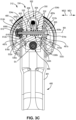
- FIG. 3C is a cross-sectional view taken along line C-C in FIG. 3A .
- FIG. 4A is a partial isometric view from the first lateral side of spray gun 312 showing trigger 480 dismounted from gun body 334.
- FIG 4B is a partial isometric view from the second lateral side of spray gun 312 showing trigger 480 dismounted from gun body 334.
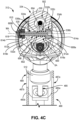
- FIG. 4C is a cross-sectional view taken along line C-C in FIG. 4B .
- FIGS. 3A-3C show trigger mount 600 in a retaining state in which trigger 480 is retained on gun body 334 and operably positioned relative to valving components actuatable by trigger 480.
- FIGS. 4A-4C show trigger mount 600 in a mounting state in which trigger 480 can be mounted to gun body 334 or removed from gun body 334.
- FIGS. 4A-4C further show trigger 480 dismounted from gun body 334.
- FIGS. 3A-4C are discussed together.
- Trigger 480 includes pull 481, arms 483a, 483b, and receiver 485.
- Body bore 530, of gun body 334 is shown.
- Body bore 530 includes bore portions 532a, 532b, 532c in the example shown.
- Mount opening 487a is formed in arm 483a
- mount opening 487b is formed in arm 483b
- mount slot 489 is formed in arm 483b.
- Trigger mount 600 includes mount body 602 and spring 640.
- Mount body 602 includes shaft 606, pivot head 608a, and pivot head 608b.
- Shaft 606 includes shank 610.
- Pivot head 608a includes bearing surface 612a and tool interface 614a.
- Pivot head 608b includes bearing surface 612b and tool interface 614b.
- Pivot head 608b further includes head bore 618.
- Trigger 480 is mountable to and dismountable from gun body 334. Trigger 480 is configured to shift in mount direction TD1 during mounting and in mount direction TD2 during dismounting. Trigger 480 can be considered to slide relative to gun body 334 during mounting and dismounting. Trigger 480 is configured to slide along a displacement axis DA during mounting and dismounting of trigger 480 on gun body 334.
- Spray gun 312 is configured to receive flows of spray fluid and compressed air and to emit an atomized spray of the spray fluid for application on a target surface.
- Spray gun 312 is configured as a manual spray gun, though it is understood that not all examples are so limited.
- Gun body 334 supports other components of spray gun 312.
- the user can depress trigger 480 with the fingers of the hand that is grasping handle 484 to actuate spray gun 312 between the spray and non-spray states.
- Trigger 480 controls actuation of one or both of the spray valve 322, controlling emission of spray fluid, and the air valve 490, controlling one or more flows of compressed gas, to respective open states.
- Trigger 480 is mounted to gun body 334 by trigger mount 600.
- Trigger 480 mount holds trigger 480 on gun body 334.
- trigger mount 600 provides a pivot point on which trigger 480 can pivot to actuate the one or more valves to respective open states.
- Trigger mount 600 can be considered to form a bearing pivot on which trigger 480 is rotatably supported.
- the trigger 480 is configured to pivot on pivot axis PA.
- Pivot axis PA extends through gun body 334.
- Body bore 530 extends along pivot axis PA. In the example shown, body bore 530 extends fully laterally through gun body 334 along pivot axis PA. In the example shown, body bore 530 extends fully axially through gun body 334 along pivot axis PA. Body bore 530 is open through lateral side 534a of gun body 334 and through lateral side 534b of gun body 334.
- body bore 530 is formed from multiple bores having different radial widths.
- Bore portion 532a extends into gun body 334 from lateral side 534a.
- Bore portion 532c extends into gun body 334 from lateral side 534b.
- Bore portion 532b extends between and connects bore portions 532a, 532c.
- bore portion 532a has a first radial width
- bore portion 532b has a second radial width greater than the first radial width
- bore portion 532c has a third radial width greater than the second radial width.
- one or more of bore portions 532a-532c are formed as cylinders.
- Body bore 530 can be formed by stepped cylinders in some examples. In such an example, bore portions 532a-532c can have varying diameters, with a diameter of bore portion 532c larger than a diameter of bore portion 532b, which diameter of bore portion 532b is larger than a diameter of bore portion 532a.
- the varying radial widths of the bore portions 532 facilitates mounting and retention of trigger mount 600 on gun body 334.
- Shoulder 536a is formed between bore portion 532a and bore portion 532b. Shoulder 536a extends radially outward from pivot axis PA and can be considered to form a base of bore portion 532b.
- Shoulder 536b is formed between bore portion 532b and bore portion 532c. Shoulder 536b extends radially outward from pivot axis PA and can be considered to form a base of bore portion 532c.
- bore portion 532a extends from lateral side 534a to shoulder 536a
- bore portion 532b extends from shoulder 536a to shoulder 536b
- bore portion 532c extends from shoulder 536b to lateral side 534b.
- Mount body 602 is configured to interface with trigger 480 to connect trigger 480 to gun body 334 with trigger mount 600 in the retaining state.
- Mount body 602 is at least partially disposed within body bore 530. In the example shown, mount body 602 extends fully axially through body bore 530 with trigger mount 600 in the retaining state. Mount body 602 can, in some examples, extend a full length of body bore 530 with trigger mount 600 in the mounting state.
- Mount body 602 projects out of body bore 530 with trigger mount 600 in both the retaining state and mounting state in the example shown.
- Mount body 602 extends out of body bore 530 in axial direction MD2.
- Mount body 602 is movable relative to gun body 334 to actuate trigger mount 600 between the retaining and mounting states.
- mount body 602 is configured to shift axially along mount axis MA to move between positions associated with the retaining state and the mounting state.
- mount body 602 is configured to shift in axial direction MD2 along mount axis MA to place trigger mount 600 in the mounting state and is configured to shift in axial direction MD1 along mount axis MA to place trigger in the retaining state.
- Axial directions MD1, MD2 can also be referred to as lateral directions.
- Mount body 602 shifts in a single lateral direction relative to gun body 334 to actuate trigger mount 600 from the retaining state to the mounting state.
- Mount body 602 shifts in a single lateral direction relative to gun body 334 to actuate trigger mount 600 from the mounting state to the retaining state.
- mount body 602 interfaces with arm 483a and arm 483b of trigger 480 to mount trigger 480 to gun body 334.
- Pivot head 608a is disposed at a first axial end of mount body 602. Pivot head 608a is configured to interface with arm 483a. Pivot head 608a extends into mount opening 487a through arm 483a to interface with trigger 480. In the example shown, pivot head 608a extends fully axially through mount opening 487a with trigger mount 600 in the retaining state. Pivot head 608a is withdrawn from mount opening 487a with trigger mount 600 in the mounting state. In the example shown, all portions of mount body 602 are withdrawn from mount opening 487a with trigger mount 600 in the mounting state.
- mount opening 487a is unoccupied by mount body 602 with trigger mount 600 in the mounting state. Withdrawing mount body 602 from mount opening 487a allows trigger 480 to pass over pivot head 608a and by mount body 602 during mounting and dismounting of trigger 480 on gun body 334.
- Pivot head 608a has a radial width larger than the radial width of bore portion 532b. Shoulder 536b axially overlaps with pivot head 608a along mount axis MA. Shoulder 536b prevents pivot head 608a from passing in axial direction MD2 and fully through body bore 530. Such a configuration assists in retaining trigger mount 600 mounted to gun body 334 both with trigger 480 mounted to gun body 334 and with trigger 480 dismounted from gun body 334. Head face 616a of pivot head 608a is oriented axially inwards towards gun body 334. Head face 616a is oriented in axial direction MD2 and towards pivot head 608b. Head face 616a axially overlaps with shoulder 536b along mount axis MA. Head face 616a is configured to interface with shoulder 536b to limit movement of mount body 602 in axial direction MD2 through body bore 530.
- pivot head 608a has a radial width smaller than the radial width of bore portion 532c. The smaller radial with of pivot head 608a relative to bore portion 532c facilitates pivot head 608a passing into bore portion 532c during operation.
- pivot head 608a is recessed within bore portion 532c with trigger mount 600 in the mounting state.
- Bearing surface 612a is annularly surrounded by the material of gun body 334 with pivot head 608a recessed in bore portion 532c, in the example shown.
- pivot head 608a is fully recessed within bore portion 532c with trigger mount 600 in the mounting state such that pivot head 608a does not pass axially outward of lateral side 534b in axial direction MD1 with trigger mount 600 in the mounting state. It is understood that in some examples pivot head 608a is not disposed within gun body 334 with trigger mount 600 in the mounting state.
- bore portion 532c can be formed to only partially surround pivot head 608a.
- pivot head 608a is formed monolithically, but it is understood that not all examples are so limited. In some examples, pivot head 608a can be formed by multiple components functioning together. For example, a washer can brace mount body 602 to prevent displacement out of body bore 530 in first direction MD1 (the washer forming head face 616a) and a nut can provide the bearing surface for the trigger (e.g., bearing surface 612a).
- Bearing surface 612a is formed on an exterior of pivot head 608a.
- Bearing surface 612a is a surface on which arm 483a rides with trigger 480 mounted to gun body 334 and as trigger pivots to cause spraying by spray gun 312.
- Bearing surface 612a can be formed as a cylindrical surface.
- Bearing surface 612a is disposed within mount opening 487a with trigger 480 mounted to gun body 334. In the example shown, mount opening 487a is fully radially enclosed.
- trigger 480 can bear on bearing surface 612a 360-degrees about the mount axis MA.
- Such a configuration increases the operational lifespan of trigger 480 by reducing wear on the material defining mount opening 487a by distributing loads fully about the mount axis MA.
- Bearing surface 612a is larger than at least a portion of body bore 530 such that bearing surface 612a cannot pass axially through body bore 530.
- Tool interface 614a is formed on pivot head 608a.
- Tool interface 614a is configured to receive torque from a tool to facilitate assembly of mount body 602.
- tool interface 614a is disposed on mount axis MA and extends into pivot head 608a along mount axis MA.
- tool interface 614a can be formed as one or more slots, a faceted bore, etc.
- tool interface 614a is configured to receive a driver (e.g., screw driver). It is understood, however, that not all examples are so limited.
- tool interface 614a can be formed as a faceted exterior surface, among other options.
- Pivot head 608b is disposed at a second axial end of mount body 602. Pivot head 608b is disposed at an opposite end of mount body 602 from pivot head 608a. Pivot head 608b is configured to interface with arm 483b. Pivot head 608b extends into mount opening 487b through arm 483b to interface with trigger 480. In the example shown, pivot head 608b extends fully axially through mount opening 487b with trigger mount 600 in the retaining state. Pivot head 608b is withdrawn from mount opening 487b with trigger mount 600 in the mounting state. While pivot head 608b is withdrawn from mount opening 487b, mount body 602 passes through mount opening 487b with trigger mount 600 in the mounting state. In the example shown, at least a portion of mount opening 487b is occupied by mount body 602 with trigger mount 600 in both the retaining state and the mounting state and with trigger 480 in the mounting position associated with the trigger engaged state.
- pivot head 608b is formed monolithically, but it is understood that not all examples are so limited. In some examples, pivot head 608b can be formed by multiple components functioning together. For example, a washer can brace mount body 602 to prevent displacement out of body bore 530 in direction MD2 (the washer forming head face 616b) and a nut can provide the bearing surface for the trigger (e.g., bearing surface 612b).
- Slot 489 is formed in trigger arm 483b. Slot 489 extends through trigger arm 483b and is open to mount opening 487b. Slot 489 is open on a radial exterior of arm 483b relative to mount axis MA and is open through a radial exterior of mount opening 487b relative to mount axis MA.
- Slot 489 defines the displacement axis DA along which the trigger 480 shifts between the trigger engaged state, in which the trigger 480 is movable to open a first valve (e.g., spray valve 322 or air valve 490)s, and a disengaged state, in which the trigger 480 is spaced from the first valve assembly (e.g., assembly 338 or assembly 476) such that the first valve assembly can pass axially by the trigger 480 along the spray axis SA.
- Slot 489 facilitates mount body 602 passing out of mount opening 487b during dismounting of trigger 480.
- Mount body 602 passes out of mount opening 487b and out of overlap with trigger 480 trough slot 489.
- Slot 489 facilitates mount body 602 passing into mount opening 487b during mounting of trigger 480.
- Mount body 602 passes into overlap with trigger 480 and into mount opening 487b through slot 489.
- Mount body 602 moves within slot 489 as trigger 480 passes by mount body 602 during mounting and dismounting.
- Mount body 602 can slide within slot 489 during mounting and dismounting of trigger 480.
- a width W1 of slot 489 is smaller than a radial width of pivot head 608b (e.g., diameter relative to mount axis MA), preventing trigger 480 from shifting along displacement axis DA relative to pivot head 608b with pivot head 608b disposed within mount opening 487.
- the width W1 of slot 489 is smaller than a diameter of bearing surface 612b, which bearing surface 612b is a portion of mount body 602 on which arm 483b rides with trigger mount 600 in the retaining state and holding trigger 480 on gun body 334.
- Shaft 606 has a radial width smaller than the width W1 of slot 489 such that trigger 480 can move along displacement axis DA relative to mount body 602 with shaft 606 passing within and through slot 489.
- Withdrawing pivot head 608b from mount opening 487b e.g., by axial movement along mount axis MA
- trigger 480 to pass by pivot head 608b (e.g., by radial movement relative to mount axis MA) during mounting and dismounting of trigger 480 on gun body 334.
- Pivot head 608b has a radial width larger than the radial width of bore portion 532a.
- gun body 334 axially overlaps with pivot head 608b along mount axis MA.
- Head face 616b of pivot head 608b is oriented axially inwards towards gun body 334.
- Head face 616b is oriented in axial direction MD1 and towards pivot head 608a.
- Head face 616b axially overlaps with lateral side 534a along mount axis MA.
- Head face 616b is configured to interface with gun body 334 to limit movement of mount body 602 in axial direction MD1 through body bore 530.
- Lateral side 534a prevents pivot head 608b from passing in axial direction MD1 and fully through body bore 530.
- pivot head 608b can partially recess within gun body 334 in some examples.
- body bore 530 is sized such that pivot head 608b cannot pass fully through body bore 530 in axial direction MD1.
- Bearing surface 612b is formed on an exterior of pivot head 608b.
- Bearing surface 612b is a surface of mount body 602 on which arm 483b rides with trigger 480 mounted to gun body 334 and as trigger 480 pivots to cause spraying by spray gun 312.
- Bearing surface 612b can be formed as a cylindrical surface.
- Bearing surface 612b is disposed within mount opening 487b with trigger 480 mounted to gun body 334. In the example shown, mount opening 487b is partially radially enclosed with slot 489 extending into mount opening 487b.
- Trigger 480 can bear on bearing surface 612b less than 360-degrees about the mount axis MA.
- Bearing surface 612b is larger than at least a portion of body bore 530 such that bearing surface 612b cannot pass axially through body bore 530.
- arm 483b includes slot 489 while arm 483a does not include a corresponding slot.
- Mount opening 487b does not extends fully about bearing surface 612b while mount opening 487a is enclosed and does extend fully about bearing surface 612a.
- the single slot configuration of trigger 480 allows for unidirectional displacement of mount body 602 to actuate trigger mount 600 between states and for unidirectional displacement of trigger 480 during mounting and dismounting.
- the enclosed mount opening 487a provides for increased lifespan for trigger 480 by distributing wear fully about mount axis MA while the partially enclosed mount opening 487b provides for a compact configuration and simple operation of spray gun 312 and trigger mount 600 by unidirectional actuation and mounting.
- Tool interface 614b is formed on pivot head 608b. Tool interface 614b is configured to receive torque from a tool to facilitate assembly of mount body 602.
- tool interface 614b is formed on a radial exterior of pivot head 608b.
- Tool interface 614b is disposed axially outward of bearing surface 612b relative to gun body 334. Bearing surface 612b is disposed axially between tool interface 614b and gun body 334.
- Tool interface 614b is formed as a faceted surface in the example shown.
- tool interface 614a is configured to be received by a torquing tool (e.g., a wrench, socket, etc.). While tool interface 614b is shown as formed on an exterior of pivot head 608b it is understood that tool interface 614b can extend into pivot head 608b to receive torque, similar to tool interface 614a.
- a torquing tool e.g., a wrench, socket, etc.
- Pivot head 608a and pivot head 608b are disposed on opposite lateral sides of gun body 334. Pivot head 608a and pivot head 608b are disposed such that at least a portion of the gun body 334 is disposed directly axially between pivot head 608a and pivot head 608b.
- Trigger mount 600 is configured such that mount body 602 remains mounted to gun body 334 with trigger 480 in both the trigger engaged state and the disengaged state.
- Pivot head 608a is sized relative to body bore 530 to prevent mount body 602 from passing out of body bore 530 in axial direction MD2.
- Pivot head 608b is sized relative to body bore 530 to prevent mount body 602 from passing out of body bore 530 in axial direction MD1.
- Mount body 602 remaining mounted to gun body 334 with trigger 480 being either mounted or dismounted simplifies operation of spray gun 312 and makes for easier operation by the user by eliminating loose parts.
- Shaft 606 extends between and connects pivot head 608a and pivot head 608b.
- Shaft 606 is elongate along mount axis MA.
- Shaft 606 can be cylindrical, among other options.
- the exterior surface of shaft 606 is faceted or otherwise non-circular and body bore 530 (e.g., bore portion 532a) is similarly shaped such that shaft 606 is keyed to body bore 530. Keying shaft 606 to body bore 530 prevents rotation of mount body 602 on mount axis MA such that trigger 480 can pivot about mount axis MA and move relative to mount body 602.
- Shaft 606 extends between the axially inner sides of pivot heads 608a, 608b.
- shaft 606 is monolithically formed with pivot head 608a.
- shaft 606 is formed separately from and mounted to pivot head 608b.
- shaft 606 and pivot head 608b can be removably mounted to each other, such as by interfaced threading between shaft 606 and pivot head 608b.
- Shaft 606 and pivot head 608b can be removably mounted such that torquing pivot head 608a and/or pivot head 608b on mount axis MA can break the connection between shaft 606 and pivot head 608b.
- shaft 606 include a threaded shank 610 that extends into a threaded head bore 618 in pivot head 608b to form the threaded interface between shaft 606 and pivot head 608b.
- head bore 618 is open fully axially through pivot head 608b.
- head bore 618 extends only partially through pivot head 608b such that head bore 618 is not open through an outer axial surface of pivot head 608b, providing a smooth outer surface for interfacing with by the user.
- shaft 606 and pivot head 608b can be permanently connected, such as by press-fitting, adhesive, welding, etc.
- shaft 606 is shown as monolithic with pivot head 608a in the example shown, it is understood that not all examples are so limited.
- Shaft 606 can be integrally formed with pivot head 608b and mounted to pivot head 608a.
- shaft 606 can be formed separately from both pivot heads 608a, 608b and can be assembled to both pivot heads 608a, 608b.
- Shaft 606 extends between and connects pivot head 608a, 608b for unidirectional actuation between the retaining and mounting states.
- shaft 606 is formed as a rigid structure that connects pivot head 608a and pivot head 608b together for simultaneous movement along mount axis MA.
- Shaft 606 rigidly connects pivot head 608a and pivot head 608b.
- Force exerted on pivot head 608a in axial direction MD2 is transmitted through shaft 606 to pivot head 608b to cause pivot head 608b to displace in axial direction MD2 together with pivot head 608a.
- force exerted on pivot head 608a in axial direction MD1 is transmitted through shaft 606 to pivot head 608b to cause pivot head 608b to displace in axial direction MD2 together with pivot head 608a.
- Forces exerted in opposite directions on mount body 602 can cancel out. For example, exerting a first force on pivot head 608b in axial direction MD1 and a second force on pivot head 608a in axial direction MD2 can cancel out those equal forces causing mount body 602 to remain stationary.
- Shaft 606 extends within body bore 530.
- Shaft 606 is at least partially disposed within body bore 530 with trigger mount 600 in both the retaining state and the mounting state.
- a smaller portion of the length of the shaft 606 is disposed within body bore 530 with trigger mount 600 in the mounting state as compared to when trigger mount 600 in the retaining state.
- a greater portion of the length of the shaft 606 is disposed outside of the body bore 530 with trigger mount 600 in the mounting state as compared to when trigger mount 600 in the retaining state.
- Spring 640 is configured to bias trigger mount 600 to the retaining state. Spring 640 biases mount body 602 in axial direction MD1. In the example shown, spring 640 interfaces with mount body 602 to bias mount body 602 in axial direction MD 1. Spring 640 interfaces with a pivot head 608a to bias mount body 602. Spring 640 interfaces with head face 616a oriented in axial direction MD2. Spring 640 extends between shoulder 536a and pivot head 608a. Spring 640 is captured axially between head face 616a and shoulder 536a. Spring 640 braces against shoulder 536a to bias mount body 602 in axial direction MD1 relative to gun body 334.
- Spring 640 is disposed around a portion of mount body 602. In the example shown, spring 640 is disposed around shaft 606. Shaft 606 extends through spring 640 and axially beyond spring 640. In the example shown, shaft 606 has a radial width smaller than a radial width of the spring 640. In the example shown, the diameter of the spring 640 is greater than the diameter of the shaft 606. The diameter of the spring 640 is smaller than the diameter of bearing surface 612a. Spring 640 is formed as a coil spring in the example shown, though it is understood that not all examples are so limited.
- trigger mount 600 is actuated to facilitate mounting of trigger 480 to spray gun 312 and dismounting of trigger 480 from spray gun 312.
- Trigger mount 600 supports trigger 480 on gun body 334 such that trigger 480 can pivot on mount axis MA and can actuate one or more valves open to cause spraying by spray gun 312.
- Trigger mount 600 pivotably supports trigger 480.
- Trigger 480 is initially dismounted from gun body 334 such that trigger 480 is disconnected from gun body 334 and not supported by gun body 334.
- Trigger 480 is shifted vertically upwards from a bottom side of gun body 334 such that arms 483a, 483b are disposed on opposite lateral sides 534a, 534b of gun body 334.
- Trigger mount 600 is actuated to the mounting state.
- Mount body 602 is displaced in axial direction MD2 from the position shown in FIG. 3C to the position shown in FIG. 4C .
- an axial force in axial direction MD2 can be applied to pivot head 608a.
- the force is transmitted through shaft 606 to pivot head 608b.
- Pivot head 608a, shaft 606, and pivot head 608b displace in axial direction MD2.
- Pivot head 608a is received within bore portion 532c and is recessed within body bore 530.
- Spring 640 is compressed between pivot head 608a and shoulder 536a.
- Pivot head 608b is spaced from gun body 334 such that an axial gap is formed along mount axis MA between pivot head 608b and gun body 334.
- Mount body 602 is displaced from a position associated with the retaining state ( FIG. 3C ) to a position associated with the mounting state ( FIG. 4C ). Mount body 602 is displaced laterally relative to gun body 334 to the position associated with the mounting state. Mount body 602 shifts in axial direction MD2 to place trigger mount 600 in the mounting state.
- Pivot head 608a is disposed axially between lateral sides 534a, 534b. Pivot head 608a is disposed axially between arm 483a and arm 483b along mount axis MA. Pivot head 608b is spaced axially outward of gun body 334. Pivot head 608b is disposed such that arm 483b is disposed axially between pivot head 608b and gun body 334. Arm 483b is disposed axially between pivot head 608b and lateral side 534b of gun body 334. Arm 483b is disposed axially between pivot head 608b and pivot head 608a. Arm 483b is disposed in an axial gap formed between pivot head 608b and lateral side 534b.
- trigger 480 With mount body 602 in the position associated with the mounting state, trigger 480 is able to pass by mount body 602 to be mounted on gun body 334. Trigger 480 is shifted from a position associated with the disengaged state of trigger 480, in which the trigger 480 is spaced from the first valve assembly (e.g., control assembly 338, control assembly 476) such that the first valve assembly can pass axially by the trigger 480 along the spray axis SA for mounting and dismounting, to a position associated with the engaged state of trigger 480, in which the trigger 480 is movable to open the first valve of the first valve assembly.
- the first valve assembly e.g., control assembly 338, control assembly 4766
- trigger 480 shifts upwards from a bottom side of gun body 334 and into the gap along spray axis SA between front block 494 and rear block 496.
- Trigger 480 shifts upwards such that gun body 334 is received in the clevis formed by arms 483a, 483b.
- Trigger 480 shifts upwards such that a valve shaft of a valve of spray gun 312 is disposed in receiver 485 of trigger 480.
- Receiver 485 is formed as a slot in the body of trigger 480 in the example shown.
- Arm 483a is disposed on a first lateral side of gun body 334 during mounting of trigger 480. Arm 483a is spaced in axial direction MD1 relative to mount body 602 as trigger 480 shifts to the engaged state. Arm 483a is spaced in axial direction MD1 relative to pivot head 608a and pivot head 608b during mounting of trigger 480. In the example shown, arm 483a passes over mount body 602 such that mount opening 487a is aligned with pivot head 608a.
- Arm 483b is disposed on a second lateral side of gun body 334 during mounting of trigger 480. Arm 483b is disposed axially between different portions of mount body 602. Arm 483b is disposed axially between the axial ends of mount body 602. Arm 483b is spaced in axial direction MD1 from pivot head 608b and in axial direction MD2 from pivot head 608a. Arm 483b does not radially overlap with either pivot head 608b during mounting relative to mount axis MA. Arm 483b passes by pivot head 608b at a location axially between pivot head 608b and gun body 334. In the example shown, a portion of arm 483b axially overlaps with both pivot head 608b and gun body 334 along mount axis MA during at least a portion of the displacement of trigger 480 from the disengaged state to the engaged state.
- Arm 483 is positioned such that pivot head 608b is axially aligned with mount opening 487b.
- trigger 480 shifts relative to gun body 334 and/or gun body 334 shifts relative to trigger 480 such that shaft 606 passes through slot 489 and into mount opening 487b.
- the relative movement occurs along displacement axis DA that is aligned with slot 489.
- Slot 489 can be considered to define the displacement axis DA.
- the shaft 606 passing through slot 489 and into mount opening 487b aligns pivot head 608b with mount opening 487b.
- Mount opening 487b shifts radially relative to mount axis MA during mounting and dismounting of trigger 480.
- Trigger mount 600 With trigger 480 disposed in the position associated with the engaged state, the trigger mount 600 is actuated to the retaining state to connect trigger 480 to gun body 334. Trigger mount 600 connects trigger 480 to gun body 334 and holds trigger 480 in the engaged state. Mount body 602 shifts laterally relative to the gun body 334 and engages with trigger 480. Mount body 602 mechanically supports trigger 480 on gun body 334. In the example shown, mount body 602 is released and spring 640 displaces mount body 602 in axial direction MD1. Spring 640 exerts a driving axial force on pivot head 608a, displacing pivot head 608a and causing pivot head 608 to pull shaft 606 and pivot head 608b in axial direction MD1.
- Pivot head 608a shifts in axial direction MD1 and enters into mount opening 487a.
- Pivot head 608b shifts in axial direction MD1 and enters into mount opening 487b.
- Pivot heads 608a, 608b shift in the same axial direction to enter into mount openings 487a, 487b to connect trigger 480 to gun body 334.
- pivot head 608b limits displacement in axial direction MD1.
- Pivot head 608b is sized such that pivot head 608b cannot pass through body bore 530 in axial direction MD1.
- an axially inner side of pivot head 608b e.g., head face 616b engages with gun body 334 to limit displacement of mount body 602 in axial direction MD1.
- Mount body 602 is thereby retained on gun body 334 with trigger mount 600 in both the retaining state and the mounting state.
- Mount body 602 is sized such that spring 640 does not cause mount body 602 to dismount from gun body 334 when trigger 480 is dismounted from gun body 334.
- Mount body 602 displaces in axial direction MD1 to the position associated with the retaining state.
- mount body 602 is sized such that bearing surface 612a is disposed directly within mount opening 487a with mount body 602 at the limit of displacement in axial direction MD1.
- Mount body 602 is further sized such that bearing surface 612b is disposed directly within mount opening 487b with mount body 602 at the limit of displacement in axial direction MD1.
- Bearing surfaces 612a, 612b rotatably support trigger 480 on mount axis MA.
- Trigger 480 is pivotable on mount axis MA such that mount axis MA can also be considered to form a pivot axis.
- Trigger 480 can actuate both the spray valve 322 and the air valve 490 to respective open states.
- Trigger 480 is removable from gun body 334 to facilitate maintenance, removal, repair, etc. of a one or more spray valves.
- the valves can be formed as part of one or more cartridge assemblies mountable to the gun body 334.
- Trigger 480 is displaced from the trigger engaged state to the disengaged state to allow for mounting or removal of one or more of the valve cartridges.
- trigger 480 is fully dismounted from gun body 334 with trigger 480 in the disengaged state.
- Trigger 480 is disconnected from gun body 334 such that trigger 480 is not supported by gun body 334 when in the disengaged state.
- Trigger 480 is dismounted by actuating trigger mount 600 from the retaining state to the mounting state and then displacing trigger 480 relative to gun body 334 and/or gun body 334 relative to trigger 480 such that gun body 334 passes out from the clevis of trigger 480.
- mount body 602 is displaced laterally such that pivot head 608a is removed from mount opening 487a and pivot head 608b is removed from mount opening 487b.
- a single axial input on pivot head 608a can displace each of pivot heads 608a, 608b and shaft 606 along mount axis MA. Pivot heads 608a, 608b both shift in axial direction MD2.
- Mount body 602 is removed from mount opening 487a and mount body 602 extends through mount opening 487b.
- Trigger 480 shifts along displacement axis DA downward away from gun body 334.
- Gun body 334 passes from being directly between arms 483a, 483b to not being disposed directly between arms 483a, 483b.
- trigger 480 shifts such that arm 483a passes over mount body 602 and arm 483b passes off of mount body 602.
- Shaft 606 passes within slot 489 to dismount arm 483b.
- Arm 483b radially overlaps with mount body 602 and slot 489 allows arm 483b to pass radially by mount body 602 relative to mount axis MA.
- Arm 483a is spaced axially outward of mount body 602 and does not radially overlap mount body 602 along mount axis MA during dismounting of trigger 480.
- Trigger 480 passes by mount body 602 and is disconnected from gun body 334. After arm 483 passes by mount body 602 the mount body 602 can return to the position associated with the retaining state. Spring 640 drives mount body 602 in axial direction MD1 and back to the position associated with the retaining state. Trigger 480 is dismounted from gun body 334 while trigger mount 600 remains connected to gun body 334 and supported by gun body 334. The one or more valve cartridges can be dismounted for servicing, remounting, replacement, etc. The same or a new trigger 480 can be mounted to the gun body 334 by the trigger mount 600 to resume spraying.
- Trigger mount 600 is disposed directly between at least one passage that conveys compressed gas and the spray axis SA along which the one or more valves are disposed for actuation by the trigger 480.
- common passage 502 radially overlaps with trigger mount 600 relative to spray axis SA such that both shaping and atomizing air flow radially outward of trigger mount 600 and at locations that overlap with trigger mount 600.
- Trigger mount 600 is configured to provide a compact configuration for both gun body 334 and trigger 480.
- Trigger 480 fully dismounts from gun body 334 in the example shown.
- Trigger 480 fully dismounting from gun body 334 eliminates the need for elongate channels to receive mount body 602 as trigger 480 slides but remains mounted to gun body 334. It is understood that in some examples, trigger 480 can remain mounted to gun body 334 while in the disengaged state.
- trigger 480 can include a set of secondary openings similar to mount openings 487a, 487b that are spaced from mount openings 487a, 487b along axis DA.
- the mount body 602 can engage the secondary openings to maintain trigger 480 mounted on gun body 334 but in a position in which trigger 480 is spaced from spray axis SA to allow for mounting and dismounting of valves on gun body 334.
- the compact configuration of trigger 480 reduces material and manufacturing costs and provides for a simplified configuration. Further, a single trigger 480 can be removed from one gun body 334 that is utilized for spraying with a first fluid type and utilized on a second gun body 334 that is utilized for spraying with a second fluid type. Worn triggers 480 can also be easily removed and replaced.
- Mount body 602 shifts laterally relative to gun body 334 from the retaining position associated with the retaining state to the mounting position associated with the mounting state.
- Mount body 602 shifts axially along mount axis MA.
- Mount body 602 shifting in a single axial direction as a single unit facilitates a compact configuration of gun body 334.
- Body bore 530 does not need to be sized to receive both pivot heads 608a, 608b; instead, pivot head 608b remains outside of gun body 334 while pivot head 608a is recessed within gun body 334.
- Such a configuration facilitates a laterally compact gun body 334, reducing material and manufacturing costs.
- the compact configuration can reduce weight of gun body 334, reducing user fatigue and providing for more efficient spray operations.
- Body bore 530 is disposed directly vertically between an air-conveying passage and spray axis SA.
- the pivot of trigger 480 is disposed at a location that is within an area defined by the various flow passages.
- the pivot of trigger 480 is disposed in an area bordered by flow passages that convey compressed gas (vertically above, longitudinally forward and behind (along the spray axis SA)) and bordered by the spray axis SA.
- Such an area is best seen in FIGS. 2A and 2B .
- Disposing the pivot in such an area facilitates a compact configuration of gun body 334, reducing material and manufacturing costs.
- the compact configuration can reduce weight of gun body 334, reducing user fatigue and providing for more efficient spray operations.
- Mount body 602 and trigger 480 are configured such that trigger 480 shifts in a single direction during mounting and in a single direction during dismounting.
- Trigger 480 shifts in a first direction along displacement axis DA to mount to gun body 334 and in an opposite second direction along axis DA to dismount from gun body 334.
- the single-directional axial movement provides for a compact mounting footprint within which trigger 480 moves, such as compared to multi-directional movement such as with an open hook that moves up past the pivot and then over and downward.
- Such single directional movement also simplifies the mounting and dismounting process for the user.
- the user is able to fully actuate trigger mount 600 to the retaining state with a single finger.
- the user can apply axial force to pivot head 608a to displace mount body 602 with the single finger.
- Trigger mount 600 receives a single actuating force to displace from the retaining state to the mounting state.
- Axial force is applied to pivot head 608a to displace mount body 602 in axial direction MD2.
- the single displacement disengages mount body 602 from arm 483a and from arm 483b.
- Applying a single axial force to disconnect trigger 480 from trigger mount 600 further facilitates forming gun body 334 and mount body 602 in compact configurations.
- the gun body 334 is laterally wide enough to support mount body 602 but is not required to receive multiple detents with trigger 480 disconnected.
- Such a configuration also provides for simpler mounting and dismounting, reducing complexity for the user and reducing downtime.
- Trigger mount 600 receives a single actuating force to displace from the mounting state to the retaining state. Axial force is applied to pivot head 608a to displace mount body 602 in axial direction MD 1. Spring 640 biases trigger mount 600 towards the retaining state such that trigger mount 600 is normally in the retaining state. Trigger mount 600 being normally in the retaining state maintains trigger 480 on gun body 334 without requiring additional input from the user, preventing inadvertent disconnecting of trigger 480.
- FIG. 5A is a first isometric view of trigger 1480.
- FIG. 5B is a second isometric view of trigger 1480.
- FIG. 5C is a side elevational view of trigger 1480.
- FIG. 6 is an enlarged isometric view of a mounting interface of a trigger 1480 on a spray gun 312.
- FIGS. 5A-6 are discussed together.
- Trigger 1480 is substantially similar to trigger 480 (best seen in FIGS. 3A-4C ). Components of trigger 1480 similar to components of trigger 480 are indicated with the same reference number except increased by "1000" (e.g., pull 1481 and pull 481).
- Trigger 1480 includes pull 1481, arms 1483a, 1483b, receiver 1485, mount openings1487a, 1487b, and mount slot 1489.
- Mount opening 1487a includes tool connector 1622 and trigger bearing surface 1624a.
- Mount opening 1487b includes trigger bearing surface 1624b.
- Trigger 1480 is configured to mount to and dismount from gun body 334 in the same manner as trigger 480, discussed in detail above.
- the trigger 1480 is mountable to gun body by the trigger mount 600.
- Trigger mount 600 holds trigger 1480 on gun body 334.
- trigger mount 600 provides a pivot point on which trigger 1480 can pivot to actuate the one or more valves to respective open states.
- Trigger mount 600 can be considered to form a bearing pivot on which trigger 1480 is rotatably supported.
- the trigger 1480 is configured to pivot on pivot axis PA.
- Pull 1481 includes forward surface 1626 that is configured to be engaged by one or more fingers of the user to actuate trigger 1480 during spray operations of the spray gun 312.
- Arms 1483a, 1483b extend from pull 1481.
- Arms 1483a, 1483b are configured to be disposed on opposite lateral sides of the gun body 334 with trigger 1480 mounted to spray gun 312.
- Receiver 1485 is formed as a slot in the body of trigger 1480 in the example shown.
- Receiver 1485 is configured to extend around a valve shaft of a valve of the spray gun 312 and can axially overlap with coupler 492 such that trigger 1480 can actuate the spray valves by the structure defining the slot of receiver 1485 engaging the coupler 492.
- Mount opening 1487b is formed through arm 1483b.
- Trigger bearing surface 1624b defines mount opening 1487b.
- Trigger bearing surface 1624b is configured to engage with pivot head 608b to ride on pivot head 608b.
- Trigger bearing surface 1624b is formed as a partial ring in the example shown.
- Mount slot 1489 extends through trigger arm 1483b and is open to allow the shaft 606 of trigger mount 600 to pass into and out of mount opening 1487b.
- the mount openings 1487a, 1487b are disposed coaxially on a pivot axis PA on which the trigger 1480 is configured to pivot when mounted to spray gun 312 to control spraying by spray gun 312.
- the trigger bearing surface 1624b is formed by bearing piece 1628b.
- Bearing piece 1628b is formed separately from trigger arm 1483b and is fixed to the trigger arm 1483b.
- trigger arm 1483b can be overmolded on bearing piece 1628b.
- Bearing piece 1628b can be formed from a different material than the material forming trigger arm 1483b.
- bearing piece 1628b can be formed from metal, such as steel, carbide, etc., while trigger arm 1483b can be formed from polymer.
- Mount opening 1487a is formed through arm 1483a.
- Trigger bearing surface 1624a defines mount opening 1487a.
- Trigger bearing surface 1624a is configured to engage with pivot head 608a to ride on pivot head 608a.
- Trigger bearing surface 1624a is formed fully annularly about the mount opening 1487a in the example shown. The mount opening 1487a is closed in the example shown.
- Tool connector 1622 is formed about mount opening 1487a.
- Tool connector 1622 is configured to interface with surfaces of another component of spray gun 312 such that the trigger 1480 can exert force on the other component by the tool connector 1622.
- the tool connector 1622 is configured to exert torque on the other component such that trigger 1480 can drive rotational displacement of the other component by the tool connector 1622.
- the tool connector 1622 is formed as a hexed surface that extends about mount opening 1487a, though it is understood that not all examples are so limited.
- trigger 1480 can include additional or alternative tool interfaces.
- trigger 1480 can include one or more projections that are shaped to extend into or receive the other component to exert a driving force on the other component.
- the one or more projections can be shaped as a hexed projection or chamber, star, flat, Phillips head, Torx head, or other shape suitable for exerting torque on the other component.
- the one or more projections can be configured to interface with tool interfaces 614a, 614b of the trigger mount 600. In some examples, such one or more projections can extend from an outer surface 1630 of either one or both of trigger arms 1483a, 1483b.
- the one or more projections can extend from laterally outer sides 1632 of the trigger arms 1483a, 1483b.
- the tool interface can be formed as one or more projections configured as a pick such as for exerting a lever force on a component or for cleaning out oof nozzle 328 or orifices through air cap 392.
- the trigger bearing surface 1624a is formed by bearing piece 1628a.
- the tool connector 1622 is also formed by bearing piece 1628a.
- Bearing piece 1628a is formed separately from trigger arm 1483a and is fixed to the trigger arm 1483a.
- trigger arm 1483a can be overmolded on bearing piece 1628a.
- Bearing piece 1628b can be formed from a different material than the material forming trigger arm 1483b.
- bearing piece 1628b can be formed from metal, such as steel, carbide, etc., while trigger arm 1483b can be formed from polymer.
- the tool connector 1622 and the trigger bearing surface 1624a are both formed by bearing piece 1628a.
- the tool connector 1622 is formed by a plurality of interface surfaces 1634 that extend about the mount opening 1487a to define the mount opening 1487a.
- the interface surfaces 1634 define a circular bearing opening inscribed in the hexagonal tool opening that is also defined by the interface surfaces 1634.
- the circular bearing opening is configured to receive the pivot head 608a such that the pivot head 608a rides on the portions of interface surfaces 1634 defining the inscribed circular bearing opening.
- the trigger 1480 is configured such that a portion of each interface surface 1634 rides on the pivot head 608a.
- the trigger 1480 is configured such that less than the full circumferential length CL of each interface surface 1634 contacts and rides on the pivot head 608a. Up to the full length CL of each interface surface 1634 can contact a corresponding surface on the component that the tool connector 1622 contacts to torque the other component.
- Trigger 1480 provides significant advantages. Trigger 1480 can mount to spray gun 312 to actuate one or more valves of the spray gun 312 to control spraying by the spray gun 312.
- the trigger 1480 is configured to mount and dismount by shifting relative to gun body 334 to connect to and disconnect from trigger mount 600.
- the trigger bearing surfaces 1624a, 1624b ride on the pivots heads 608a, 608b, respectively, such that trigger 1480 can smoothly pivot on the mount axis MA.
- FIG. 7A is an isometric partially exploded view of spray gun 312.
- FIG. 7B is an isometric partially exploded view of spray gun 312.
- FIG. 8 is an isometric view of trigger 1480 and a spray control assembly 338.
- Spray control assembly 338 can also be referred to as a cartridge.
- FIGS. 7A-8 are discussed together.
- a keyed interface is formed between cartridge body 364 and trigger 1480 in the example shown.
- the keyed interface prevents the trigger 1480 from rotating relative to the cartridge body 364 with the tool connector 1622 radially overlapped with the mount head 1636.
- the keyed interface is formed by a portion of cartridge body 364 extending into a portion of trigger 1480, not all examples are so limited.
- a portion of trigger 1480 can extend into a portion of cartridge body 364, such as by an array of prongs extending into an array of bores in cartridge body 364, among other options.
- the keyed interface can be formed around and coaxially with the nozzle 328.
- the trigger 1480 can additionally or alternatively be configured to engage with a flow control assembly 476 that controls flows of compressed air through spray gun 312 to facilitate mounting and dismounting of the flow control assembly 476 by interfacing with the trigger 1480.
- FIG. 9 is an isometric view of trigger 1480'.
- Trigger 1480' is substantially similar to trigger 1480, except trigger 1480' includes projections 1640 that are configured to extend into an interface with receivers of a component, such as a valve assembly, of a spray gun to exert force on that component for mounting or dismounting.
- the projections 1640 are disposed in an array about the axis PA in the example shown.
- FIG. 10 is an elevational view showing engagement between an air cap 326 and spray control assembly 338.
- FIG. 11A is an isometric view of spray control assembly 338.
- FIG. 11B is an elevational end view of spray control assembly 338.
- Air cap 326 is configured to engage with spray control assembly 338 at a keyed interface such that air cap 326 can exert torque on spray control assembly 338 during installation and/or removal of spray control assembly 338.
- Air cap 326 is configured to receive flows of compressed gas (e.g., compressed air) and to output those flows to shape and/or atomize the spray fluid output from spray control assembly 338.
- Air cap 326 includes horns 446 that project from a body of air cap 326. Horns 446 are configured to output a portion of the compressed gas. In the example shown, the horns 446 also form an interface component of the air cap 326 that interfaces with the spray control assembly 338 to exert torque on the spray control assembly 338.
- Spray control assembly 338 is configured to be mounted to and/or dismounted from the gun body 334 of the spray gun 312 by a cartridge tool.
- the spray control assembly 338 is configured such that spray control assembly 338 can be dismounted by interfacing with a single one of multiple different tools.
- ring 426 includes ring flats 1650 that form a faceted exterior of cartridge body 364.
- the ring flats 1650 can be engaged by a tool, such as a wrench, so the tool can exert torque on the spray control assembly 338 for installation or removal.
- Cartridge body 364 can additionally or alternatively include mount head 1636.
- the mount head 1636 can be engaged by a tool configured to exert torque via engagement with the mount surfaces 1638 forming the faceted exterior of mount head 1636.
- mount head 1636 can be engaged by the trigger 1480 such that the trigger 1480 forms the cartridge tool.
- the mount head 1636 can be engaged by a wrench to torque the spray control assembly 338.
- Spray control assembly 338 can additionally or alternatively include horn slots 1642. Horn slots 1642 form receivers on the spray control assembly 338 into which horns 446 of the air cap 326 can extend such that rotation of the air cap 326 exerts torque on the spray control assembly 338. As such, air cap 326 can form a cartridge tool.
- the spray control assembly 338 includes horn slots 1642.
- Horn slots 1642 are configured to receive the horns 446 of the air cap 326.
- Horn slots 1642 are formed in the cartridge body 364.
- the horn slots 1642 are formed in ring 426 of cartridge body 364.
- the horn slots 1642 are open radially outwards away from the spray axis SA.
- the horn slots 1642 are closed radially inwards towards the spray axis SA.
- Each horn slot 1642 includes a base 1644 on an inner radial side of the horn slot 1642.
- the horn slots 1642 extend into a radially outer side of the ring 426 but do not extend fully radially through the ring 426.
- the horn slots 1642 do not extend into ring lip 1646 that interfaces with air cap 326 to form a sealed interface between air cap 326 and the spray control assembly 338 with the spray control assembly 338 and air cap 326 installed on the spray gun 312.
- the ring lip 1646 is an angled, annular surface that mates with the air cap 326.
- Horn slots 1642 include side walls 1648.
- the side walls 1648 are disposed at the circumferential sides of the horn slot 1642.
- the side walls 1648 are configured to circumferentially overlap with a horn 446 of the air cap 326 with the horn 446 disposed in the horn slot 1642.
- the horn 446 can interface with the side wall 4648 to exert torque on the spray control assembly 338 for installation and removal.
- side walls 1648 can converge towards each other as the side walls 1648 extend from the open axial end of horn slot 1642 and in the upstream direction AD 1.
- Such a configuration can facilitate reception of the horns 446, which can include horn sides 1652 that converge towards each other as the horn 446 extends away from the body of the air cap 326.
- base 1644 of horn slot 1642 can be sloped.
- the horn slot 1642 can be configured such that a depth of the horn slot 1642 decreases from the open axial end of horn slot 1642 and as horn slot 1642 extends axially into cartridge body 364.
- the sloped base 1644 can facilitate reception and interfacing with the sloped inner surface 1654 of the horns 446.
- the height H of the horn slot 1642 can decrease from an open end of the horn slot 1642, through which the horn 446 can enter into and be removed from the horn slot 1642, and in the upstream direction AD1 towards collar 424.
- a user can quickly and efficiently install or remove spray control assembly 338 with air cap 326.
- Air cap 326 is removed in order to access the spray control assembly 338 for removal. With the air cap 326 already dismounted, the air cap 326 can be turned around and directly engaged with the spray control assembly 338. The horns 446 are inserted into the opposed horn slots 1642. The air cap 326 can then be rotated to exert torque on the spray control assembly 338 to unthread the spray control assembly 338 from the spray gun 312 and remove the spray control assembly 338 for servicing or replacement.
- Spray control assembly 338 is installed on spray gun 312 prior to connecting air cap 326 to spray gun 312.
- the horns 446 can be inserted into horn slots 1642 and the air cap 326 can be rotated to exert torque on the spray control assembly 338 and threadedly engage the spray control assembly 338 and spray gun 312. Having the air cap 326 interface with the spray control assembly 338 provides time and cost savings and eliminates the need for additional tools to install or remove the spray control assembly 338.
- a spray gun includes a gun body; a gun bore extending within the gun body, the gun bore extending along a spray axis; a body bore extending through the gun body and along a mount axis; a first valve assembly at least partially disposed within the bore, the first valve assembly including a first valve configured to control emission of spray fluid from the spray gun; a trigger mountable to the gun body, the trigger configured to actuate the first valve from a closed state to an open state, wherein the trigger is movable relative to the gun body between an engaged state, in which the trigger is movable to open the first valve, and a disengaged state, in which the trigger is spaced from the first valve assembly such that the first valve assembly can pass axially by the trigger along the spray axis; and a trigger mount configured to mount the trigger to the gun body, the trigger mount actuatable between a retaining state, in which the trigger mount connects the trigger to the gun body and holds the trigger in the engaged state, and a mounting state, in which the trigger is dismount
- the trigger mount includes a mount body at least partially disposed within the body bore, the mount body projecting out of the body bore in a first direction along the axis to interface with a first arm of the trigger and the mount body projecting out of the body bore in a second direction along the axis to interface with a second arm of the trigger.
- the mount body is configured to displace in the second direction along the mount axis to place the trigger mount in the mounting state.
- the spray gun of the preceding paragraph can optionally include, additionally and/or alternatively, any one or more of the following features, configurations and/or additional components:
- the mount body includes a shaft elongate along the mount axis; a first pivot head disposed at a first end of the shaft, the first pivot head configured to interface with the first arm to mount the trigger to the gun body; a second pivot head disposed at a second end of the shaft, the second pivot head configured to interface with the second arm to mount the trigger to the gun body; the first pivot head radially larger than the shaft and the second pivot head radially larger than the shaft.
- the second pivot head is disposed at least partially outside of the gun body with the trigger mount in both the retaining state and the mounting state.
- the first pivot head includes a first cylindrical bearing surface on which the first arm rides with the trigger mounted to the trigger mount.
- the second pivot head includes a second cylindrical bearing surface on which the second arm rides with the trigger mounted to the trigger mount.
- the first cylindrical bearing surface is spaced in the second direction along the mount axis from the first arm with the trigger mount in the mounting state, and wherein the second cylindrical bearing surface is spaced in the second direction along the mount axis from the second arm with the trigger mount in the mounting state.
- At least one of the first pivot head and the second pivot head is formed separately from the shaft and mounted to the shaft.
- the first pivot head is formed monolithically with the shaft and the second pivot head is formed separately from the shaft.
- the shaft and the second pivot head and connected by a threaded interface.
- the shaft and the second pivot head are press-fit together.
- the first pivot head includes a first tool interface configured to receive a torquing input from a first tool, the first tool interface disposed axially outward of the first cylindrical bearing surface.
- the first tool interface is disposed on the mount axis.
- the second pivot head includes a second tool interface configured to receive a torquing input from a second tool, the second tool interface disposed axially outward of the second cylindrical bearing surface.
- the second tool interface is formed as a faceted exterior of the second pivot head.
- a diameter of the first cylindrical bearing surface is larger than at least one portion of the mount bore such that the first pivot head cannot pass through the mount bore in the second direction along the mount axis.
- a diameter of the second cylindrical bearing surface is larger than at least one portion of the mount bore such that the second pivot head cannot pass through the mount bore in the first direction along the mount axis.
- a diameter of the second cylindrical bearing surface is larger than at least one portion of the mount bore such that the second pivot head cannot pass through the mount bore in the first direction along the mount axis.
- a spring interfacing with the mount body and biasing the mount body in the first direction along the mount axis and into the retaining state.
- the spring interfaces with the gun body and the first pivot head.
- the body bore includes a first bore portion having a first radial width, the first bore portion extending in the gun body from a first lateral side of the gun body; a second bore portion extending from the first bore portion and having a second radial width greater than the first radial width; wherein the mount body extends through the first bore portion and the second bore portion and the spring is braced against a first shoulder formed between the first bore portion and the second bore portion.
- a diameter of the spring is larger than a diameter of the first bore portion.
- the body bore further comprises a third bore portion having a third radial width, the third bore portion extending into the gun body from a second lateral side of the gun body, wherein the third radial width is greater than the second radial width.
- a radial width of the first pivot head is greater than the second radial width and smaller than the third radial width.
- a spring interfacing with the mount body and biasing the mount body in the first direction along the mount axis and into the retaining state.
- An axial length of the mount body along the mount axis is the same with the trigger mount in the retaining state and with the trigger mount in the mounting state.
- the trigger further comprises a pull; the first arm extending from the pull; the second arm extending from the pull; a first mount opening through the first arm, the mount body disposed within the first mount opening with the trigger mount supporting the trigger; and a second mount opening through the second arm, the mount body disposed within the second mount opening with the trigger mount supporting the trigger.
- the mount body is removed from the first mount opening with the trigger mount in the mounting state and the trigger in a spray position associated with the engaged state, and the mount body extends through the second mount opening with the trigger mount in the mounting state and the trigger in the spray position.
- the trigger further comprises a mount slot extending through the second arm and open to the second mount opening.
- the mount slot defines a displacement axis along which the trigger shifts between the engaged state and the disengaged state.
- the mount body slides within the mount slot during mounting and dismounting of the trigger.
- the first mount opening is fully radially enclosed.
- the trigger moves vertically downwards from the engaged state to the disengaged state.
- the body bore is open on a first lateral side of the gun body and a second lateral side of the gun body.
- a second valve assembly at least partially disposed within the bore, the second valve assembly including a second valve configured to control flow of compressed gas within the spray gun, wherein the trigger is configured to actuate the second valve from a closed state to an open state.
- the first valve is spaced in a first direction along the spray axis from the trigger and the second valve is spaced in a second direction along the spray axis from the trigger.
- a spray gun includes a gun body; a gun bore extending within the gun body, the gun bore extending along a spray axis; a body bore extending through the gun body and along a mount axis; a first valve assembly at least partially disposed within the bore, the first valve assembly including a first valve configured to control emission of spray fluid from the spray gun; a trigger mountable to the gun body, the trigger configured to actuate the first valve from a closed state to an open state, wherein the trigger is movable relative to the gun body between an engaged state, in which the trigger is movable to open the first valve, and a disengaged state, in which the trigger is spaced from the first valve assembly such that the first valve assembly can pass axially by the trigger along the spray axis; and a trigger mount configured to mount the trigger to the gun body, the trigger mount actuatable between a retaining state, in which the trigger mount connects the trigger to the gun body and holds the trigger in the engaged state, and a mounting state, in which the trigger is dismount
- the trigger mount includes a mount body at least partially disposed within the body bore and movable relative to the gun body, the mount body configured to displace in a single direction along the mount axis to disengage from a first trigger arm of the trigger and a second trigger arm of the trigger and actuate the trigger mount from the retaining state to the mounting state.
- a method of assembling a spray gun includes displacing a mount body of a trigger mount in a first direction along a mount axis of a body bore formed in a gun body of the spray gun; passing a trigger by the mount body such that a first pivot head of the mount body is aligned with a first mount opening through a first arm of the trigger and such that a second pivot head of the mount body is aligned with a second mount opening through a second arm of the trigger; and displacing the mount body in a second direction along the mount axis such that the first pivot head enters into the first mount opening and such that the second pivot head enters into the second mount opening.
- Displacing the mount body in the second direction along the mount axis comprises pushing the mount body in the second direction with a spring disposed within the body bore.
- Passing the trigger by the mount body further comprises passing the first arm over the first pivot head at a location axially spaced in the second direction from the first pivot head and gun body; and passing the second arm by the second pivot head at a location axially between the second pivot head and the gun body along the mount axis.
- a method of disassembling a spray gun includes displacing a mount body of a trigger mount in a first direction along a mount axis of a body bore formed in a gun body of the spray gun such that a first pivot head of the mount body passes out of a first mount opening through a first arm of a trigger of the spray gun and such that a second pivot head of the mount body passes out of a second mount opening through a second arm of the trigger; and passing the trigger by the mount body to dismount the trigger from the gun body.
- a trigger for use with a spray gun includes a trigger pull; a first arm extending from thee trigger pull; a second arm extending from the trigger pull; a first mount opening formed through the first arm, the first mount opening including a first trigger bearing surface configured to ride on a pivot of the spray gun during actuation of the trigger; a second mount opening formed through the second arm, the second mount opening including a second trigger bearing surface configured to ride on the pivot of the spray gun during actuation of the trigger; and a tool connector configured to interface with a component of the spray gun to exert a force on the component of the spray gun during one or both of mounting and dismounting of the component.
- the trigger of the preceding paragraph can optionally include, additionally and/or alternatively, any one or more of the following features, configurations and/or additional components:
- the tool connector at least partially defines the first mount opening.
- the tool connector is at least partially formed by the first trigger bearing surface.
- the first mount opening is at least partially defined by a plurality of interface surfaces that extend about the first mount opening, and wherein the plurality of interface surfaces form both the first bearing surface and the tool connector.
- the first mount opening and the second mount opening are disposed coaxially on a pivot axis.
- the first mount opening is non-circular.
- the second mount opening is circular.
- the tool connector is configured to torque the component.
- the tool interface includes one or more projections extending from the first arm.
- the one or more projections includes a plurality of projections that are arrayed about an axis.
- a first bearing piece connected to the first arm and defining the first mount opening, wherein the first bearing piece is formed from a first material and the first arm is formed from a second material different from the first material.
- the second material is a polymer.
- a mount slot is formed through the second arm and open into the second mount opening.
- a method of servicing a spray gun includes disconnecting a trigger from a gun body of the spray gun; interfacing the trigger with a component of the spray gun; and exerting force on the component, by the trigger, to disconnect the component from the spray gun.
- Interfacing the trigger with the component of the spray gun comprises interfacing the trigger with a valve cartridge supported by a gun body of the spray gun.
- Interfacing the trigger with the component of the spray gun comprises receiving a portion of the component within a tool connector of the trigger.
- Interfacing the trigger with the component of the spray gun comprises receiving a portion of a tool connector of the trigger within the component.
- Interfacing the trigger with the valve cartridge supported by the gun body of the spray gun comprises receiving a portion of the valve cartridge within a first mount opening through a first arm of the trigger, wherein the first mount opening receives a pivot head such that the trigger rides on the pivot head with the trigger mounted to the gun body.
- Exerting force on the component, by the trigger, to disconnect the component from the spray gun comprises exerting torque on the component by the trigger.
- Exerting force on the component, by the trigger, to disconnect the component from the spray gun comprises driving rotation of the component by the trigger to loosen a threaded interface holding the component.
- a cartridge for a spray gun includes a cartridge body extending along an axis and defining a flow chamber within an interior of the cartridge body; a nozzle formed at a first end of the cartridge body, the nozzle configured to output spray fluid from the flow chamber in a first direction along the axis; at least one fluid port extending through the cartridge body between the exterior of the cartridge body and the flow chamber formed within an interior of the cartridge body; and a first horn slot formed in the cartridge body and a second horn slot formed in the cartridge body, the first horn slot and the second horn slot open in the first direction along the axis.
- the cartridge of the preceding paragraph can optionally include, additionally and/or alternatively, any one or more of the following features, configurations and/or additional components:
- the cartridge body includes an axially projecting ring, the first horn slot is formed on the ring, and the second horn slot is formed on the ring.
- the first horn slot is open radially outward and closed radially inward.
- the first horn slot does not extend fully radially through the ring.
- the first horn slot is disposed 180-degrees about the axis from the second horn slot.
- Exerting force on the component, by the air cap, to disconnect the component from the spray gun comprises rotating the air cap on an axis to exert torque on the cartridge and cause rotation of the cartridge relative to the gun body.
- Exerting force on the component, by the air cap, to disconnect the component from the spray gun comprises rotating the air cap on an axis to exert torque on the component.
Landscapes
- Physics & Mathematics (AREA)
- Fluid Mechanics (AREA)
- Nozzles (AREA)
Abstract
A spray gun (312) is configured to emit spray fluid and compressed air that impinges on the spray fluid to atomize the spray fluid. A trigger (480) actuates one or more valves of the spray gun (312) to cause spraying by the spray gun (312). The trigger (480) is mounted to a gun body of the spray gun by a trigger mount (600). The trigger (480) is removable from the gun body (334) and includes one or more tool interfaces (614b) for connecting and/or disconnecting components of the spray gun (312).
Description
- This application claims priority to
U.S. Provisional Application No. 63/537,319 filed September 8, 2023 U.S. Provisional Application No. 63/569,401 filed March 25, 2024 - This disclosure relates to spray systems. More specifically, this disclosure relates to spray guns and components thereof for use in spray systems.
- Spray guns can be used to spray fluids on surfaces. For example, spray guns can be used to spray a liquid such as paint, lacquer, finishes, and other coatings on furniture, cabinets, appliances, equipment, fabricated components, etc.
- Some spray guns utilize compressed gas, such as compressed air, to atomize the spray fluid into a desired spray pattern. Typically, the spray fluid is placed under pressure by a piston, diaphragm, or other positive displacement pump. The pump outputs the spray fluid under pressure to the spray gun, such as through a direct connection or through a flexible hose. The spray gun is used to dispense the spray fluid. The spray gun can be attached to the end of the hose opposite the pump. In this way, the spray gun does not include a pump, but rather releases spray fluid pumped to the spray gun through the hose. The spray gun atomizes the spray fluid under pressure into a spray pattern, which is applied to a surface.
- The compressed gas is emitted to assist in atomizing and, in some examples, shaping the fluid spray. The spray guns emit the compressed air through an air cap and the compressed air atomizes the spray fluid and can shape the spray fluid into a desired pattern.
- Valves control flows of the spray fluid and the compressed gas for emission from the spray gun. The valves can be actuated to open states by a trigger. The trigger requires removal from the gun body for mounting and dismounting of one or more of the valves, which mounting and dismounting can include manipulating multiple retainers. The one or more valves can be disposed within cartridges that mount to the spray gun. The cartridges require tightening and loosening by a tool, such as a wrench, during installation and removal.
- According to an aspect of the present disclosure, a spray gun includes a gun body; a gun bore extending within the gun body, the gun bore extending along a spray axis; a body bore extending through the gun body and along a mount axis; a first valve assembly at least partially disposed within the bore, the first valve assembly including a first valve configured to control emission of spray fluid from the spray gun; a trigger mountable to the gun body, the trigger configured to actuate the first valve from a closed state to an open state, wherein the trigger is movable relative to the gun body between an engaged state, in which the trigger is movable to open the first valve, and a disengaged state, in which the trigger is spaced from the first valve assembly such that the first valve assembly can pass axially by the trigger along the spray axis; and a trigger mount configured to mount the trigger to the gun body, the trigger mount actuatable between a retaining state, in which the trigger mount connects the trigger to the gun body and holds the trigger in the engaged state, and a mounting state, in which the trigger is dismountable from the trigger mount and gun body. The trigger mount includes a mount body at least partially disposed within the body bore, the mount body projecting out of the body bore in a first direction along the axis to interface with a first arm of the trigger and the mount body projecting out of the body bore in a second direction along the axis to interface with a second arm of the trigger. The mount body is configured to displace in the second direction along the mount axis to place the trigger mount in the mounting state.
- According to an additional or alternative aspect of the present disclosure, a spray gun includes a gun body; a gun bore extending within the gun body, the gun bore extending along a spray axis; a body bore extending through the gun body and along a mount axis; a first valve assembly at least partially disposed within the bore, the first valve assembly including a first valve configured to control emission of spray fluid from the spray gun; a trigger mountable to the gun body, the trigger configured to actuate the first valve from a closed state to an open state, wherein the trigger is movable relative to the gun body between an engaged state, in which the trigger is movable to open the first valve, and a disengaged state, in which the trigger is spaced from the first valve assembly such that the first valve assembly can pass axially by the trigger along the spray axis; and a trigger mount configured to mount the trigger to the gun body, the trigger mount actuatable between a retaining state, in which the trigger mount connects the trigger to the gun body and holds the trigger in the engaged state, and a mounting state, in which the trigger is dismountable from the trigger mount and gun body. The trigger mount includes a mount body at least partially disposed within the body bore and movable relative to the gun body, the mount body configured to displace in a single direction along the mount axis to disengage from a first trigger arm of the trigger and a second trigger arm of the trigger and actuate the trigger mount from the retaining state to the mounting state.
- According to another additional or alternative aspect of the present disclosure, a method of assembling a spray gun includes displacing a mount body of a trigger mount in a first direction along a mount axis of a body bore formed in a gun body of the spray gun; passing a trigger by the mount body such that a first pivot head of the mount body is aligned with a first mount opening through a first arm of the trigger and such that a second pivot head of the mount body is aligned with a second mount opening through a second arm of the trigger; and displacing the mount body in a second direction along the mount axis such that the first pivot head enters into the first mount opening and such that the second pivot head enters into the second mount opening.
- According to yet another additional or alterative aspect of the present disclosure, a method of disassembling a spray gun includes displacing a mount body of a trigger mount in a first direction along a mount axis of a body bore formed in a gun body of the spray gun such that a first pivot head of the mount body passes out of a first mount opening through a first arm of a trigger of the spray gun and such that a second pivot head of the mount body passes out of a second mount opening through a second arm of the trigger; and passing the trigger by the mount body to dismount the trigger from the gun body.
- According to yet another additional or alternative aspect of the disclosure, a trigger for use with a spray gun includes a trigger pull; a first arm extending from thee trigger pull; a second arm extending from the trigger pull; a first mount opening formed through the first arm, the first mount opening including a first trigger bearing surface configured to ride on a pivot of the spray gun during actuation of the trigger; a second mount opening formed through the second arm, the second mount opening including a second trigger bearing surface configured to ride on the pivot of the spray gun during actuation of the trigger; and a tool connector configured to interface with a component of the spray gun to exert a force on the component of the spray gun during one or both of mounting and dismounting of the component.
- According to yet another additional or alternative aspect of the disclosure, a method of servicing a spray gun includes disconnecting a trigger from a gun body of the spray gun; interfacing the trigger with a component of the spray gun; and exerting force on the component, by the trigger, to disconnect the component from the spray gun.
- According to yet another additional or alternative aspect of the disclosure, a cartridge for a spray gun includes a cartridge body extending along an axis and defining a flow chamber within an interior of the cartridge body; a nozzle formed at a first end of the cartridge body, the nozzle configured to output spray fluid from the flow chamber in a first direction along the axis; at least one fluid port extending through the cartridge body between the exterior of the cartridge body and the flow chamber formed within an interior of the cartridge body; and a first horn slot formed in the cartridge body and a second horn slot formed in the cartridge body, the first horn slot and the second horn slot open in the first direction along the axis.
- According to yet another additional or alternative aspect of the disclosure, a method of servicing a spray gun, includes disconnecting an air cap from a gun body of the spray gun; interfacing the air cap with a component of the spray gun; and exerting force on the component, by the air cap, to disconnect the component from the spray gun.
-
-
FIG. 1 is an isometric view of a spray gun. -
FIG. 2A is a cross-sectional view taken along line 2-2 inFIG. 1 showing the spray valve in a closed state. -
FIG. 2B is a cross-sectional view taken along line 2-2 inFIG. 1 showing the spray valve in an open state. -
FIG. 3A is a partial isometric view from a first lateral side of a spray gun showing the trigger mounted to the gun body. -
FIG 3B is a partial isometric view from a second lateral side of the spray gun showing the trigger mounted to the gun body. -
FIG. 3C is a cross-sectional view taken along line C-C inFIG. 3A . -
FIG. 4A is a partial isometric view from the first lateral side of the spray gun showing the trigger dismounted from the gun body. -
FIG 4B is a partial isometric view from the second lateral side of the spray gun showing the trigger dismounted from the gun body. -
FIG. 4C is a cross-sectional view taken along line C-C inFIG. 4A . -
FIG. 5A is a first isometric view of a trigger. -
FIG. 5B is a second isometric view of the trigger. -
FIG. 5C is a side elevational view of the trigger. -
FIG. 6 is an enlarged isometric view of a mounting interface of a trigger on a spray gun. -
FIG. 7A is an isometric partially exploded view of a spray gun. -
FIG. 7B is an isometric partially exploded view of the spray gun. -
FIG. 8 is an isometric view of a trigger and a spray control assembly. -
FIG. 9 is an isometric view of a trigger. -
FIG. 10 is a partial elevational view showing an air cap and cartridge interface. -
FIG. 11 is an isometric view of a cartridge for a spray gun. - This disclosure relates to fluid spraying. More specifically, this disclosure relates to component assembly for a spray gun. A trigger is movable between a trigger engaged state, in which the trigger is movable to open a first valve of the spray gun, and a disengaged state, in which the trigger is spaced from the first valve assembly such that the first valve assembly can pass axially by the trigger along a spray axis. A trigger mount engages the trigger to support the trigger on the gun body. The trigger mount is actuatable between a retaining state, in which the trigger mount can hold the trigger on the gun body and in the trigger engaged state, and a mounting state, in which the trigger can be mounted to or dismounted from the gun body.
- Spray guns according to the disclosure are configured to emit a spray of spray fluid, such as liquid paints, varnishes, lacquers, fine finishes, high-gloss finishes, waterborne coatings, solvent-borne coatings, etc. The spray gun can be used to apply coatings to surfaces, furniture, cabinets, appliances, equipment, fabricated components, etc., among other options. The spray gun also emits compressed gas. An atomization portion of the compressed gas is configured to atomize spray fluid and complete the atomization of the fan tails, preventing undesired tailing. A shaping portion of the compressed gas is configured to shape the spray pattern. The spray fluid is emitted through a nozzle and the compressed gas is emitted through an air cap surrounding the nozzle. The atomization gas is emitted with each actuation of the spray gun to a spray state while the fan gas can be set by the user between no fan gas and a maximum flow.
- According to aspects of the disclosure, the trigger mount includes a mount body that interfaces with the trigger to pivotably support the trigger on the gun body. The mount body is actuatable relative to the trigger to place the trigger mount in the retaining state and the mounting state. The mount body can be actuated by a single input to detach the trigger from the gun body. The mount body can be actuated by a single input to attach the trigger to the gun body. The mount body can shift in a single direction along the axis to connect the trigger to the gun body and in an opposite direction to disconnect the trigger from the gun body.
- The trigger can include one or more tool interfaces. The tool interfaces are configured to facilitate connection and disconnection of components of the spray gun. In some examples, the trigger includes a tool interface that is configured to engage with a portion of a valve cartridge to facilitate torquing of the valve cartridge during mounting or dismounting (e.g., to tighten or loosen a threaded interface). In some examples, the tool interface forms a pivot support of the trigger that supports the trigger on the trigger mount during spray operations.
- Components can be considered to radially overlap when those components are disposed at common axial locations along an axis. A radial line extending orthogonally from axis will extend through each of the radially overlapping components. Components can be considered to axially overlap when those components are disposed at common radial and circumferential locations relative to the axis. An axial line parallel to the axis will extend through the axially overlapping components. Components can be considered to circumferentially overlap when those components are disposed at common radial distance and axial locations along the axis, such that a circle centered on the axis passes through each of the circumferentially overlapping components.
-
FIG. 1 is an isometric view ofspray gun 312. FIG. 1A is a cross-sectional view taken along line 2-2 inFIG. 1 showing thespray valve 322 in a closed state. FIG. 1B is a cross-sectional view taken along line 2-2 inFIG. 1 showing thespray valve 322 in an open state.FIGS. 1-2B will be discussed together.Spray gun 312 is a manual spray gun configured to be held in the hand of a user and activated directly by the user to spray the spray fluid. -
Spray gun 312 includesgun body 334,air cap assembly 326,spray control assembly 338,flow control assembly 476,fan valve 478,trigger 480, andmetering valve 482.Gun body 334 includesmain body 350,gun mount 352, and handle 484.Air cap assembly 326 includesair cap 392 andcap retainer 394.Flow control assembly 476 includesdisplacement limiter 336,needle return 346,valve seal 486, andvalve spring 488.Displacement limiter 336 includeslimiter housing 356,knob 358,positioner 360, and stop 362.Needle return 346 includesreturn block 347 and returnspring 348. Spraycontrol assembly 338 includesspray valve 322,nozzle 328,cartridge body 364,needle 366,seat 368,needle seal 370, cartridge seals 372, andfluid ports 374.Cartridge body 364 includeshousing 376 andseal holder 378.Housing 376 includesinlet housing 376a andoutlet housing 376b.Needle 366 includesneedle tip 380,needle body 382, andneedle head 386. - The
spray gun 312 sprays along a spray axis SA. The axis also represents an upstream side or direction and a downstream side or direction, wherein spray fluid generally flow from the upstream direction towards the downstream direction. In the example shown, the downstream direction is the second axial direction AD2 and the upstream direction is the first axial direction AD1.Spray gun 312 can emit the spray fluid as a fan in some examples. -
Spray gun 312 is configured as a manual spray gun that is held in a hand of the user and actuated between spray and non-spray states by the user. The user can grasp handle 484 to aim and manipulatespray gun 312. The user can holdspray gun 312 and actuatespray gun 312 between the spray and non-spray states with a single hand of the user. The user can depress trigger 480 with the fingers of the hand that is graspinghandle 484 to actuatespray gun 312 between the spray and non-spray states.Trigger 480 controls actuation of thespray valve 322 and theair valve 490 to respective open states. -
Spray gun 312 is configured to receive flows of spray fluid and compressed air and to emit an atomized spray of the spray fluid for application on a target surface.Spray gun 312 is configured as a manual spray gun, though it is understood that not all examples are so limited.Gun body 334 supports other components ofspray gun 312. -
Main body 350 supports other components ofspray gun 312.Main body 350 includesfront block 494 andrear block 496.Front block 494 at least partially defines flowpaths for both spray fluid and compressed gas to flow throughspray gun 312. Rear block 496 at least partially defines flowpaths for compressed gas to flow throughspray gun 312. In the example shown,rear block 496 does not define any passages for spray fluid and is not exposed to spray fluid.Trigger gap 498 is disposed axially betweenfront block 494 andrear block 496.Trigger gap 498 is open towards a bottom side ofspray gun 312.Trigger gap 498 is closed by a portion ofmain body 350 that spans betweenfront block 494 andrear block 496. - Handle 484 extends from
main body 350. Handle 484 projects from a lower side ofmain body 350. Handle 484 extends fromrear block 496 ofmain body 350 in the example shown.Air inlet passage 500 is formed within and throughhandle 484.Air inlet passage 500 provides a flowpath for compressed gas to enter intogun body 334 and flow to the air passages withinmain body 350. -
Metering valve 482 is mounted togun body 334.Metering valve 482 is configured to connect to an air hose (such as air hose 32 (FIG. 1 )) that supplies compressed air tospray gun 312.Metering valve 482 is mountedhandle 484.Metering valve 482 is configured to control flow of compressed air tospray gun 312.Metering valve 482 is actuatable between an open state, in which the compressed air can flow intospray gun 312, and a closed state, in which the compressed air is prevented from flowing intospray gun 312. Themetering valve 482 is placed in and maintained in a desired state. Themetering valve 482 is not a check valve that is actuated between open and closed states by the flow of the compressed air. - Gun bore 406 extends fully axially though
gun body 334. Gun bore 406 is open on both thefront end 335 ofspray gun 312 and therear end 337 ofspray gun 312. Gun bore 406 extends along spray axis SA. Gun bore 406 extends fully axially throughfront block 494 such that gun bore 406 is open on both axial sides offront block 494. The portion of gun bore 406 infront block 494 is open onfront end 335 and open to triggergap 498. Gun bore 406 extends fully axially throughrear block 496 such that gun bore 406 is open on both axial sides ofrear block 496. The portion of gun bore 406 inrear block 496 is open onrear end 337 and open to triggergap 498. - A portion of gun bore 406 in
rear block 496 is directly downstream fromair inlet passage 500 and defines a portion of the compressed gas flowpath throughgun body 334.Air valve 490 divides the gun bore 406 inrear block 496 into an upstream passage that is fluidly connected toair inlet passage 500 throughout operation and a downstream passage that is fluidly connected toair inlet passage 500 withair valve 490 in the open state and that is fluidly disconnected fromair inlet passage 500 withair valve 490 in the closed state. -
Common passage 502 extends from the portion of gun bore 406 inrear block 496 and forms a portion of the compressed air flowpath throughspray gun 312.Common passage 502 receives compressed air from the gun bore 406 inrear block 496 when theair valve 490 is in the open state. Thecommon passage 502 routes the compressed air to atomization air passage 504 (an inlet of which is shown) and shapingair passage 506. Theatomization passage 504 extends toaperture 420a to output the atomization portion of the compressed airproximate baffle 418a. The shapingair passage 506 extends toaperture 420b to output the shaping portion of the compressed airproximate baffle 418b. -
Fan valve 478 is mounted togun body 334.Fan valve 478 is actuatable between an open state, in which shapingair passage 506 is open and fluidly connected tocommon passage 502 such that the shaping portion of the compressed air can flow to theair cap 392, and a closed state, in which the shapingair passage 506 is fluidly disconnected from thecommon passage 502 such that the shaping portion of the compressed air is prevented from flowing to theair cap 392.Fan valve 478 includes afan valve shaft 508 that has a shaft head that is engageable with a seat withingun body 334 to placefan valve 478 in the closed state. Thefan valve shaft 508 is accessible from outside of thegun body 334 to be manipulated by the user. In the example shown, thefan valve shaft 508 is mounted to asupport housing 510 by a threaded interface, with thesupport housing 510 mounted togun body 334. Thefan valve shaft 508 is rotated relative to thesupport housing 510 to displace thefan valve shaft 508 and place thefan valve 478 in the open or closed states. Theatomization air passage 504 is fluidly connected to thecommon passage 502 regardless of the state of thefan valve 478. As such,spray gun 312 is configured to emit atomization air during any spray operation while the shaping air can be turned on or shut off depending on the state offan valve 478. -
Gun mount 352 is disposed withinmain body 350. In the example shown,gun mount 352 is disposed withinfront block 494 ofmain body 350.Gun mount 352 can be press-fit, threaded, or otherwise secured withinmain body 350.Gun mount 352 at least partially defines the spray fluid pathway throughspray gun 312.Gun mount 352 can be considered to form a wet component ofspray gun 312 asgun mount 352 is exposed to the spray fluid during operation. - Spray
fluid fitting 512 is mounted togun body 334. Sprayfluid fitting 512 is mounted tomain body 350 in the example shown. Sprayfluid fitting 512 is mounted tofront block 494 ofmain body 350 in the example shown. Sprayfluid fitting 512 is configured to connect with a hose (e.g., a fluid hose) that supplies spray fluid tospray gun 312 under pressure. Sprayfluid fitting 512 can extend intogun mount 352 and can interface withgun mount 352. Sprayfluid fitting 512 does not extend to axially overlap withspray control assembly 338. Sprayfluid fitting 512 not axially overlapping withspray control assembly 338 along spray axis SA allowsspray control assembly 338 to be shifted into or out of gun bore 406 during mounting and dismounting without the user having to manipulatespray fluid fitting 512, as discussed in more detail below. -
Air cap assembly 326 is disposed at a first axial end ofgun body 334.Air cap assembly 326 is mounted tofront block 494.Air cap 392 is configured to emit both atomizing air and shaping air.Central orifice 408 is formed throughair cap 392.Central orifice 408 is disposed on spray axis SA.Central orifice 408 is configured to emit atomization air fromair cap 392. Shapingorifices 410 are formed inhorns 446 ofair cap 392. Shapingorifices 410 are configured to emit shaping air fromair cap 392. -
Air cap 392 is mounted togun body 334 bycap retainer 394.Cap retainer 394 extends overair cap 392 and interfaces withgun body 334 to secureair cap 392 togun body 334.Cap retainer 394 is connected tofront block 494 in the example shown.Cap retainer 394 can be mounted togun body 334 by a quick connect interface though it is understood that other connection types are possible, such as a threaded connection. In the example shown, a portion ofcap retainer 394 is configured to shift axially relative to spray axis SA to lock and unlockair cap 392 togun body 334. - Spray
control assembly 338 is configured to control emission of the spray fluid fromspray gun 312. Spraycontrol assembly 338 is mounted togun body 334. In the example shown,spray control assembly 338 is mounted withinfront block 494 ofmain body 350. Spraycontrol assembly 338 extends fully axially throughfront block 494 in the example shown. Spraycontrol assembly 338 projects out offront block 494 in both first axial direction AD1 and second axial direction AD2 in the example shown. - Spray
control assembly 338 is at least partially disposed withingun body 334. Spraycontrol assembly 338 forms a fluid cartridge that is mountable to and dismountable fromgun body 334 as a unitary assembly. Thespray control assembly 338 is a single module that can be inserted into gun bore 406 through thefront end 335 and can be removed from the gun bore 406 throughfront end 335 as the single module. -
Cartridge body 364 supports other components ofspray control assembly 338.Cartridge body 364 is at least partially disposed withingun body 334.Cartridge body 364 is secured withingun body 334 to securespray control assembly 338 relative togun body 334. In the example shown,cartridge body 364 is mounted togun mount 352 at a location withinfront block 494.Cartridge body 364 extends intogun mount 352 to interface withgun mount 352. In the example shown,cartridge body 364 extends fully axially throughgun mount 352 such thatcartridge body 364 projects out ofgun mount 352 in both first axial direction AD1 and second axial direction AD2.Cartridge body 364 is connected togun mount 352 by a threaded interface in the example shown. -
Cartridge body 364 includeshousing 376 that is configured to interface with a portion ofgun body 334 to mountspray control assembly 338 togun body 334 andcartridge body 364 includesseal holder 378 that mounts tohousing 376.Housing 376 andseal holder 378 form the exterior ofcartridge body 364. In the example shown,nozzle 328 is formed byhousing 376.Nozzle 328 is formed at a first axial end ofhousing 376 andseal holder 378 is mounted to a second axial end ofhousing 376 opposite the first axial end ofhousing 376. Spray fluid is emitted throughspray orifice 329.Nozzle 328 extends to sprayorifice 329 through which the spray fluid is emitted.Spray orifice 329 is formed at an axial end ofspray control assembly 338 in second axial direction AD2. -
Cartridge mount 412 is formed on an exterior ofcartridge body 364. In the example shown,cartridge mount 412 is formed onhousing 376.Cartridge mount 412 is configured to interface with a portion ofgun body 334 to securespray control assembly 338 togun body 334. In the example shown,cartridge mount 412 is formed by threads on the exterior ofoutlet housing 376a.Cartridge mount 412 is configured to engage with threading ongun mount 352 to securespray control assembly 338 togun body 334. -
Housing 376 at least partially defines flowpaths for spray fluid to flow tonozzle 328 and for compressed air to flow toair cap 392. In the example shown,housing 376 is formed frominlet housing 376b andoutlet housing 376a mounted together.Inlet housing 376b is configured to receive spray fluid intospray control assembly 338.Outlet housing 376a is configured to emit spray fluid fromspray control assembly 338.Inlet housing 376b andoutlet housing 376a are connected together to formhousing 376. In the example shown,inlet housing 376b andoutlet housing 376a are connected together by a threaded interface. In the example shown,inlet housing 376b includes male threading configured to interface with female threading formed onoutlet housing 376a. A portion ofinlet housing 376b extends intooutlet housing 376a to form the threaded interface therebetween. -
Baffle 418a extends radially from the exterior ofcartridge body 364.Baffle 418a extends radially fromhousing 376. In the example shown, baffle 418a extends radially fromoutlet housing 376a. In the example shown,baffle 418a is formed as a flange extending radially outwards fromcartridge body 364.Baffle 418a extends annularly aboutcartridge body 364 in the example shown.Baffle 418a can be integrally formed with other portions ofcartridge body 364. In some examples, baffle 418a can be formed monolithically with other portions ofcartridge body 364. In the example shown, baffle 418a is monolithic withhousing 376. In the example shown, baffle 418a is monolithic withoutlet housing 376. -
Baffle 418a is configured to distribute a first portion of the compressed air annularly about the spray axis SA as the first portion of the compressed air flows in second axial direction AD2. The first portion of the compressed air forms the atomization air in the example shown.Inner air chamber 414 is configured to route the first portion of the compressed air to thecentral orifice 408 ofair cap 392. Theinner air chamber 414 is formed about the spray axis SA. Theinner air chamber 414 is disposed about an exterior of thecartridge body 364. In the example shown, a portion of theinner air chamber 414 is radially bracketed by thecartridge body 364 such that a radially outer side of that portion of theinner air chamber 414 is defined by thecartridge body 364 and a radially inner side of that portion of theinner air chamber 414 is defined by thecartridge body 364. The portion of theinner air chamber 414 radially bracketed bycartridge body 364 is a downstream portion of theinner air chamber 414. Theinner air chamber 414 is disposed axially betweengun mount 352 andcentral orifice 408. The downstream portion of theinner air chamber 414 is disposed axially between theair passages 422 andcentral orifice 408. - The atomization portion of the compressed air enters into the
inner air chamber 414 throughaperture 420a on one axial side of the baffle 418a. The atomization portion of the compressed air flows in second axial direction AD2 over baffle 418a, throughair passages 422 incartridge body 364 and downstream tocentral orifice 408. The first portion of the compressed air exitsspray gun 312 throughcentral orifice 408 inair cap 392. The first portion of the compressed air exitsspray gun 312 through an annular ring formed about the portion of thecartridge body 364 definingnozzle 328. -
Baffle 418b extends radially from the exterior ofcartridge body 364.Baffle 418b extends radially fromhousing 376. In the example shown,baffle 418b extends radially fromoutlet housing 376b. In some examples,baffle 418b can be formed separately fromhousing 376 and mounted tohousing 376. In some examples,baffle 418b can be integrally formed with other portions ofcartridge body 364. In some examples,baffle 418b can be formed monolithically with other portions ofcartridge body 364. It is understood, however, that not all examples are so limited. For example,baffle 418b can be formed separately fromhousing 376 and be mounted withinfront block 494 such thatspray control assembly 338 shifts relative to thebaffle 418b during mounting and dismounting.Baffle 418b can be mounted withingun body 334 such thatbaffle 418b does not mount to and dismount fromgun body 334 withspray control assembly 338. -
Baffle 418b is configured to distribute a second portion of the compressed air annularly about the spray axis SA as the second portion of the compressed air flows in second axial direction AD2. The second portion of the compressed air forms the shaping air in the example shown. Anouter air chamber 416 is configured to route the second portion of the compressed air to theshaping orifices 410. Theouter air chamber 416 is formed about the spray axis SA. Theouter air chamber 416 is disposed about an exterior of thecartridge body 364. In the example shown, a portion of theouter air chamber 416 radially overlaps with a portion of theinner air chamber 414. Theouter air chamber 416 is disposed radially outward of theinner air chamber 414. - The shaping portion of the compressed air enters into the
outer air chamber 416 throughaperture 420b on one axial side of thebaffle 418b. The shaping portion of the compressed air is distributed about the spray axis SA bybaffle 418b and flows in second axial direction AD2 and downstream to shapingorifices 410. The shaping portion of the compressed air exitsspray gun 312 through shapingorifices 410 inair cap 392. -
Collar 424 is formed onoutlet housing 376b.Collar 424 extends radially outward relative to other portions ofoutlet housing 376b.Collar 424 is disposed axially betweennozzle 328 and baffle 418a.Collar 424 can extend fully annularly about the spray axis SA. -
Air passages 422 extend throughcollar 424.Air passages 422 are configured to route the atomization portion of the compressed air from an upstream portion of theinner air chamber 414 to the downstream portion of theinner air chamber 414. In the example shown, a plurality ofair passages 422 are formed throughcollar 424. An array of theair passages 422 can be disposed annularly about the spray axis SA. -
Ring 426 projects in second axial direction AD2 from a main body portion ofcollar 424 through whichair passages 422 are formed.Ring 426 is disposed radially betweeninner air chamber 414 andouter air chamber 416.Ring 426 projects to engage with an axially inner side ofair cap 392, sealing withair cap 392 to fluidly separateinner air passage 414 andouter air passage 416.Ring 426 defines portions ofinner air chamber 414 andouter air chamber 416 in the example shown. The portion ofinner air chamber 414 radially bracketed bycartridge body 364 is disposed radially betweenring 426 andoutlet housing 376a. - Cartridge seals 372 are disposed between
cartridge body 364 andgun body 334. Cartridge seals 372 fluidly separate wet portions and dry portions withingun body 334. In the example shown, cartridge seals 372 are disposed on the exterior ofcartridge body 364. In the example shown, cartridge seals 372 are disposed between and engage withcartridge body 364 andgun mount 352. Cartridge seals 372 axially bracket the portion of the spray fluid flowpath outside ofcartridge body 364 and inside ofgun mount 352. - In the example shown, seal
grooves 428 are formed oncartridge body 364. Cartridge seals 372 are disposed inseal grooves 428 such that cartridge seals 372 are mounted oncartridge body 364. A first one ofseal grooves 428 is disposed axially betweennozzle 328 andfluid ports 374. A second one ofseal grooves 428 is disposed axially betweenfluid ports 374 andtrigger gap 498. -
Fluid passage 430 is disposed axially between the cartridge seals 372. Thefluid passage 430 extends fully annularly aboutcartridge body 364. Thefluid passage 430 defines an annular flowpath for the spray fluid to flow fully aboutcartridge body 364 to enter intofluid ports 374 to enter intoflow chamber 432. Thefluid passage 430 facilitates spray fluid entering intoflow chamber 432 from locations disposed circumferentially aboutcartridge body 364 and spray axis SA. The flowpath fromfluid passage 430 throughfluid ports 374 and intoflow chamber 432 does not restrict flow relative to outflow throughnozzle 328, facilitating efficient and effective output of spray fluid for atomization during spray operations. -
Fluid ports 374 are formed throughcartridge body 364.Fluid ports 374 form flowpaths for the spray fluid to enter intoflow chamber 432 withincartridge body 364. In the example shown, multiplefluid ports 374 are arrayed about thecartridge body 364. Eachfluid port 374 includes an outer opening on the exterior ofcartridge body 364 that allow spray fluid to enter into thefluid port 374 fromfluid passage 430 and includes an inner opening that opens intoflow chamber 432 and allows the spray fluid to enter intoflow chamber 432. Thefluid ports 374 are disposed axially between the cartridge seals 372. Thefluid ports 374 are spaced in first axial direction AD1 fromcartridge mount 412. Thefluid ports 374 are disposed on an opposite axial side of the mating interface betweencartridge body 364 andgun body 334 fromnozzle 328. -
Seal holder 378 is connected tohousing 376. In the example shown,seal holder 378 is mounted tohousing 376 by a threaded interface formed therebetween.Seal holder 378 is disposed at an opposite axial end ofhousing 376 fromnozzle 328.Seal holder 378 extends intohousing 376 to radially overlap withhousing 376.Seal holder 378 is configured to interface withneedle seal 370 to retainneedle seal 370 withincartridge body 364. -
Needle seal 370 is configured to interface with an exterior ofneedle 366.Needle seal 370 can be considered to form a dynamic seal asneedle 366 shifts axially relative toneedle seal 370 during operation.Needle seal 370 can be formed as a seal assembly including multiple individual sealing components.Needle seal 370 is disposed in the interior ofcartridge body 364. Theflow chamber 432 ofspray control assembly 338 extends axially betweennozzle 328 andneedle seal 370.Needle seal 370 forms a sliding seal with the exterior ofneedle 366 asneedle 366 shifts between open and closed states.Needle seal 370 engages with the exterior ofneedle 366 to inhibit spray fluid from leaking in first axial direction AD1 and out ofcartridge body 364. -
Spray valve 322 is formed betweenneedle 366 andseat 368.Seat 368 is formed bycartridge body 364, in the example shown.Needle 366 is engaged withseat 368 withspray valve 322 in the closed state andneedle 366 is disengaged fromseat 368 withspray valve 322 in the open state.Needle 366 is configured as the movable component ofspray valve 322. -
Needle 366 is at least partially disposed withincartridge body 364.Needle 366 is configured to shift along spray axis SA to actuatespray valve 322 between open and closed states.Needle 366 is movable along spray axis SA and relative toseat 368 to placespray valve 322 in the open and closed states. -
Needle tip 380 is configured to engage withseat 368 to placespray valve 322 in the closed state.Needle tip 380 is disposed at one axial end ofneedle 366.Needle body 382 extends axially fromneedle tip 380. In the example shown,needle tip 380 is formed separately fromneedle body 382 and connected toneedle body 382, such as by a threaded interface. It is understood, however, that not all examples are so limited. For example,needle tip 380 andneedle body 382 can be formed monolithically. -
Needle body 382 extends in first axial direction AD1 fromneedle tip 380.Needle body 382 extends from withinflow chamber 432 to outside ofcartridge body 364.Needle body 382 extends throughneedle seal 370 and engages withneedle seal 370.Needle body 382 engaging withneedle seal 370 seals an axial end offlow chamber 432. -
Needle head 386 is disposed at an opposite axial end ofneedle body 382 fromneedle tip 380.Needle head 386 has a larger diameter thanneedle body 382. In the example shown, theneedle 366 can be considered to have a needle neck that is the same diameter as theneedle body 382. -
Coupler 492 is mounted onneedle body 382.Coupler 492 is disposed onneedle body 382 betweenneedle head 386 andcartridge body 364.Coupler 492 is disposed outside ofcartridge body 364.Coupler 492 rides onneedle body 382 and is not fixed toneedle body 382 such thatcoupler 492 can slide axially alongneedle body 382 relative toneedle body 382. The opening throughcoupler 492 is sized such thatneedle head 386 cannot pass throughcoupler 492. -
Coupler 492 is disposed on an opposite side oftrigger 480 fromcartridge body 364.Coupler 492 is sized such thattrigger 480 cannot pass overcoupler 492 astrigger 480 is actuated to cause spraying byspray gun 312. Instead, trigger 480 interfaces withcoupler 492 such thattrigger 480 can displacecoupler 492 in first axial direction AD1.Trigger 480 displacescoupler 492 to causecoupler 492 to engage withneedle head 386 and then driveneedle 366 in first axial direction AD1 to actuatespray valve 322 to the open state. Whilespray control assembly 338 is described as includingcoupler 492, it is understood that not all examples are so limited. -
Trigger 480 is mounted ongun body 334 bytrigger mount 600.Trigger mount 600 can be actuated relative togun body 334 to connecttrigger 480 togun body 334 and to disconnecttrigger 480 fromgun body 334.Trigger mount 600 is discussed in more detail below with regard toFIGS. 3A-4C . -
Flow control assembly 476 is configured to control flow of compressed air throughspray gun 312.Flow control assembly 476 includes sealing components that are configured to shift along spray axis SA to actuateair valve 490 between an open state, in which the compressed air can flow throughair valve 490 and downstream toair cap 392, and a closed state, in which the compressed air is prevented from flowing downstream toair cap 392. In the example shown,valve seal 486 forms the movable valving component ofair valve 490.Air valve 490 is formed betweenflow control assembly 476 andgun body 334 in the example shown. In the example shown, theair seat 514 that the movable valve member ofair valve 490 engages is formed bygun body 334. It is understood, however, that not all examples are so limited. For example, flowcontrol assembly 476 can include a housing that forms theair seat 514 ofair valve 490 such that both the seat and the movable valving member that defineair valve 490 are formed as components offlow control assembly 476. -
Flow control assembly 476 is also configured to manage flow of the spray fluid throughspray gun 312, thoughflow control assembly 476 is a dry component that does not contact the spray fluid.Flow control assembly 476 manages the flow of the spray fluid by limiting a displacement distance of theneedle 366 in first axial direction AD1.Flow control assembly 476 thereby sets the distance that needle 366 can displace fromseat 368, thereby setting the opening size ofspray valve 322.Flow control assembly 476 also manages the flow of the spray fluid by actuating thespray valve 322 from the open state to the closed state. -
Flow control assembly 476 is disposed coaxially withspray control assembly 338.Flow control assembly 476 is elongate along spray axis SA.Flow control assembly 476 is mounted togun body 334. In the example shown,flow control assembly 476 is mounted withinrear block 496 ofgun body 334. In the example shown,flow control assembly 476 is mounted directly torear block 496.Flow control assembly 476 is mounted togun body 334 by a threaded interface in the example shown, though it is understood that other connection types are possible. -
Flow control assembly 476 extends fully axially through the portion of the gun bore 406 formed inrear block 496.Flow control assembly 476 is mounted torear block 496 such thatflow control assembly 476 projects out ofrear block 496 in both first axial direction AD1 and second axial direction AD2.Flow control assembly 476 projects out ofrear end 337 ofspray gun 312. A portion offlow control assembly 476 projects intotrigger gap 498 formed betweenfront block 494 andrear block 496. -
Flow control assembly 476 is configured to mount tospray gun 312 as a single unitary component.Flow control assembly 476 forms a flow cartridge that is mountable and dismountable as a single module. The single module is mountable throughrear end 337 and dismountable throughrear end 337.Flow control assembly 476 andspray control assembly 338 mount in opposite axial directions and dismount in opposite axial directions. Thespray control assembly 338 shifts in first axial direction AD1 during mounting and theflow control assembly 476 shifts in first axial direction AD1 during dismounting. Theflow control assembly 476 shifts in second axial direction AD2 during mounting and thespray control assembly 338 shifts in second axial direction AD2 during dismounting. Thespray control assembly 338 and flowcontrol assembly 476 shift axially towards each other during mounting and shift axially away from each other during dismounting. -
Displacement limiter 336 forms a portion offlow control assembly 476.Displacement limiter 336 is mounted togun body 334.Displacement limiter 336 is mounted torear block 496 at a location withinrear block 496.Displacement limiter 336 is disposed at an opposite axial end ofspray gun 312 fromnozzle 328. In the example shown,displacement limiter 336 mounts togun body 334 to secure other components offlow control assembly 476 togun body 334. The interface betweendisplacement limiter 336 andgun body 334 fixesflow control assembly 476 along spray axis SA. The interface betweendisplacement limiter 336 andgun body 334 is the only mechanical connection that holdsflow control assembly 476 togun body 334 in the example shown. -
Limiter housing 356 is mounted togun body 334. In the example shown,limiter housing 356 is mounted torear block 496 ofgun body 334.Limiter housing 356 is disposed partially withingun body 334 and partially outside ofgun body 334. Limiter bore 440 extends axially throughlimiter housing 356. Limiter bore 440 is disposed coaxially on spray axis SA. In the example shown, limiter bore 440 extends fully axially throughlimiter housing 356. -
Positioner 360 is at least partially disposed withinlimiter housing 356. Stop 362 is mounted topositioner 360. In the example shown,positioner 360 includes exterior threads that engage with interior threads formed onstop 362. Stop 362 is at least partially disposed withinlimiter bore 440. Stop 362 is keyed to limiterhousing 356 such thatstop 362 does not rotate on spray axis SA. For example, at least a portion of the limiter bore 440 can include a non-circular cross-section taken in a plane normal to the spray axis SA and an exterior surface of thestop 362 can be of the same cross-sectional shape as the surface of the limiter bore 440. In some examples, the exterior ofstop 362 can be faceted and the limiter bore 440 can be similarly faceted to mate with thestop 362. Thestop 362 and limiter bore 440 can be hexed, among other options. The keyed interface prevents stop 362 from rotating on spray axis SA due to rotation ofpositioner 360. Instead, rotation ofpositioner 360 causes stop 362 to displace axially along spray axis SA due to the threaded interface betweenpositioner 360 and stop 362. - Stop 362 is configured to interface with
needle return 346 to limit displacement ofneedle return 346, and thus ofneedle 366, in second axial direction AD2. Stop 362 is configured to define a maximum opening distance ofspray valve 322. Stop 362 defines the maximum distance that needle 366 can shift away fromseat 368 and relative toseat 368 to openspray valve 322. -
Knob 358 is mounted onpositioner 360.Knob 358 is fixed topositioner 360 such that rotation ofknob 358 causes rotation ofpositioner 360.Knob 358 is disposed outside ofgun body 334.Knob 358 is disposed outside oflimiter housing 356.Knob 358 is accessible by a user such that the user can manipulateknob 358 to rotatepositioner 360 and displacestop 362 to adjust the maximum opening distance. -
Needle return 346 is disposed withingun body 334.Needle return 346 is disposed at least partially within the interior offlow control assembly 476.Needle return 346 is disposed coaxially withdisplacement limiter 336 in the example shown.Needle return 346 is disposed at least partially within limiter bore 440 in the example shown.Return block 347 extends axially into limiter bore 440 oflimiter housing 356.Needle return 346 is configured to interface withneedle 366 andbias needle 366 in second axial direction AD2 and into engagement withseat 368. -
Return block 347 is a portion ofneedle return 346 that interfaces withneedle 366.Return block 347 is movable along the spray axis SA.Return block 347 is independent of and not connected tovalve seal 486.Valve seal 486 and return block 347 can move relative to each other along spray axis SA. -
Return rod 400 ofreturn block 347 extends in second axial direction AD2 and is at least partially disposed in needle bore 516 ofvalve seal 486.Return rod 400 is configured to abut and engage withneedle 366. In the example shown, returnrod 400 engages withneedle head 386.Return rod 400 abutsneedle head 386 but is not fixed toneedle head 386 in the example shown.Return rod 400 interfaces with a face ofneedle head 386 oriented in first axial direction AD1. -
Return flange 402 extends radially outward from an exterior ofreturn block 347.Return flange 402 provides a bearing surface forreturn spring 348 to engage with.Return body 404 forms a portion ofneedle return 346 extending in first axial direction AD1 fromreturn flange 402.Return body 404 is disposed withinreturn spring 348 and can assist in aligningreturn spring 348 relative toneedle return 346.Return body 404 can be considered to form a spring guide that assists in aligningreturn spring 348 on spray axis SA. -
Return spring 348 is disposed withingun body 334 and engages withreturn block 347.Return spring 348 is disposed within an interior offlow control assembly 476 such thatreturn spring 348 is isolated from and not exposed to the compressed air flowing throughspray gun 312, in the example shown.Return spring 348 is disposed radially withinvalve seal 486 and extends into limiter bore 440 in the example shown. In the example shown,return spring 348 engages withreturn flange 402 ofreturn block 347.Return spring 348 also engages withdisplacement limiter 336. In the example shown,return spring 348 braces onstop 362.Return spring 348 is configured to biasreturn block 347, and thus needle 366 due to the engagement ofreturn rod 400 andneedle head 386, in second axial direction AD2.Return spring 348 is configured to biasneedle 366 into engagement withseat 368 to placespray valve 322 in the closed state. -
Return spring 348 is disposed outside of the flowpath of the spray fluid throughspray gun 312.Return spring 348 is a dry component that is not exposed to the spray fluid during operation. Spraycontrol assembly 338 does not include any springs in theflow chamber 432. In the example shown, thespray control assembly 338 does not include any springs that are part of thespray control assembly 338. Spraycontrol assembly 338 is mountable and dismountable as a single module that does not include any springs. The only spring that exerts a biasing force onneedle 366 isreturn spring 348, which does not directly interface withneedle 366. Instead, thereturn spring 348 is indirectly connected to theneedle 366 via theintermediate needle return 346. Thereturn spring 348 exerts a biasing force onneedle return 346 andneedle return 346 exerts a biasing force onneedle 366. Theneedle 366 is a portion of a first module mountable to thegun body 334 and thereturn spring 348 is a portion of a second module mountable to thegun body 334. -
Valve seal 486 is at least partially disposed withingun body 334.Valve seal 486 is elongate along spray axis SA.Valve seal 486 is hollow in the example shown such that a passage extends fully axially throughvalve seal 486. The passage is open in both the first axial direction AD1 into an interior ofvalve seal 486 and in second axial direction AD2 towardsnozzle 328.Valve seal 486 includesseal body 518,seal shoulder 520, andvalve shaft 522. -
Valve shaft 522 is elongate along spray axis SA.Valve shaft 522 is formed as cylinder in the example shown, though it is understood that not all examples are so limited.Valve shaft 522 projects axially out of gun bore 406 and intotrigger gap 498 in the example shown.Valve shaft 522 extends through and engages withair seal 524a.Valve shaft 522 forms a sliding seal withair seal 524a asvalve shaft 522 can slide axially relative toair seal 524a.Air seal 524a is supported byrear block 496 in the example shown.Air seal 524a is formed as a U-cup seal in this example shown, though it is understood that not all examples are so limited. The sealed interface betweenair seal 524a andvalve shaft 522 prevents compressed air from leaking out ofrear block 496 in second axial direction AD2. -
Valve seal 486 retainsneedle return 346 within the interior offlow control assembly 476. The diameter of the needle bore 516 throughvalve shaft 522 is smaller than the diameter ofreturn flange 402 ofneedle return 346. Thereturn flange 402 will interface with the interior side ofseal shoulder 520 to prevent further movement ofneedle return 346 in second axial direction AD2, retainingreturn block 347 in the interior offlow control assembly 476. -
Needle 366 andneedle return 346 interface at a location withinvalve seal 486. Specifically,needle 366 and return block 347 interface at a location withinvalve shaft 522.Needle 366 and return block 347 interface withinneedle bore 516.Valve shaft 522 can locate bothreturn block 347 andneedle 366 on spray axis SA to maintain concentricity therebetween. Maintaining the axial alignment betweenreturn block 347 andneedle 366 reduces wear onneedle 366 by drivingneedle 366 on axis SA, preventing wear toneedle 366 orseat 368 that can occur due to non-coaxial engagement therebetween. -
Seal shoulder 520 extends between and connectsvalve shaft 522 and sealbody 518.Seal shoulder 520 extends radially outward betweenvalve shaft 522 and sealbody 518. A diameter ofvalve seal 486 enlarges alongseal shoulder 520 betweenvalve shaft 522 and sealbody 518. In the example shown,seal shoulder 520 is sloped betweenvalve shaft 522 and sealbody 518 such thatseal shoulder 520 extends both axially and radially betweenvalve shaft 522 and sealbody 518. -
Seal body 518 extends in first axial direction AD1 fromseal shoulder 520.Seal body 518 extends fromseal shoulder 520 and intolimiter housing 356.Seal body 518 has a larger diameter thanvalve shaft 522 in the example shown.Seal body 518 is cylindrical in the example shown, though it is understood that not all examples are so limited. -
Seal body 518 extends intolimiter housing 356 and engages withair seal 524b.Air seal 524b engages with an exterior surface ofseal body 518.Air seal 524b is supported bylimiter housing 356 in the example shown.Air seal 524b engaging withseal body 518 andlimiter housing 356 inhibits leakage of compressed air therebetween in first axial direction AD1.Air seal 524b seals an interior offlow control assembly 476 and prevents compressed air from flowing into the interior offlow control assembly 476. -
Valve seal 486 engages withair seat 514 withair valve 490 in the closed state and is disengaged fromair seat 514 withair valve 490 in the open state. In the example shown,flow seal 526, which is supported byvalve seal 486, is configured to directly interface with theair seat 514 to placeair valve 490 in the closed state.Flow seal 526 is supported byseal shoulder 520 in the example shown.Flow seal 526 is formed separately fromvalve seal 486 and mounted onvalve seal 486 in the example shown.Flow seal 526 is configured to engage withair seat 514 to placeair valve 490 in a closed state.Flow seal 526 is spaced fromair seat 514 withair valve 490 in an open state. Whileflow control assembly 476 is described as includingflow seal 526, it is understood that not all examples are so limited. For example,valve seal 486 can be configured to directly interface withair seat 514 to placeair valve 490 in the closed state. -
Valve spring 488 interfaces withvalve seal 486 andbiases air valve 490 to the closed state.Valve spring 488biases valve seal 486 in second axial direction AD2 and into engagement withair seat 514.Valve spring 488 extends axially betweenlimiter housing 356 andvalve seal 486. In the example shown,seal body 518 ofvalve seal 486 is disposed radially withinvalve spring 488 and extends throughvalve spring 488.Valve spring 488 is disposed on an exterior offlow control assembly 476.Valve spring 488 is disposed such thatvalve spring 488 is exposed to the airflow throughspray gun 312. -
Valve spring 488 is configured to biasair valve 490 to the closed state.Return spring 348 is configured to biasspray valve 322 to the closed state. Bothvalve spring 488 and returnspring 348 are disposed withinrear block 496 in the example shown.Valve spring 488 and returnspring 348 are both formed as dry components that are not exposed to the spray fluid flowing throughspray gun 312.Valve spring 488 and returnspring 348 are disposed coaxially on spray axis SA.Valve spring 488 and returnspring 348 radially overlap with each other.Valve spring 488 is disposed radially outward ofreturn spring 348. - During operation, compressed air is provided to
spray gun 312 throughair inlet passage 500 and spray fluid is provided tospray gun 312 throughspray fluid fitting 512. Thespray valve 322 and theair valve 490 are normally in respective closed states. The compressed air flows throughair inlet passage 500 and into the gun bore 406 inrear block 496. Thevalve seal 486 is maintained in engagement with theair seat 514 byvalve spring 488 exerting an axial biasing force onvalve seal 486 in second axial direction AD2 such that theair valve 490 is in the closed state, preventing flow of compressed air in second axial direction AD1 pastair valve 490. The spray fluid flows throughspray fluid fitting 512 and enters intofluid passage 430. The spray fluid flows throughfluid ports 374 and enters intoflow chamber 432 in the interior ofspray control assembly 338. Theneedle 366 is maintained in engagement withseat 368 byreturn spring 348 exerting a force in second axial direction AD2 onneedle return 346 andneedle return 346 exerting a force onneedle 366 in second axial direction AD2 tobias needle 366 into engagement withseat 368. Thespray valve 322 is thus in the closed state, preventing flow of the spray fluid throughnozzle 328. - To cause spraying the user depresses
trigger 480. Thetrigger 480 shifts in first axial direction AD1 and engages withcoupler 492. For example, the trigger can pivot on a pivot point through thegun body 334. Thecoupler 492 exerts an axial driving force onvalve seal 486 atvalve shaft 522. The force ofvalve spring 488 is overcome andvalve seal 486 displaces in first axial direction AD1.Valve seal 486 disengages fromair seat 514 and a flowpath is opened betweenvalve seal 486 andair seat 514.Valve spring 488 is compressed betweenvalve seal 486 andlimiter housing 356.Air valve 490 is thus in the open state. - With
air valve 490 in the open state, the compressed air flows through theair valve 490 and downstream to thecommon passage 502. The compressed air flows throughcommon passage 502 and to theatomization passage 504 and shapingair passage 506. The atomization portion of the compressed air flows through theatomization passage 504 and out throughcentral orifice 408 inair cap 392. The shaping portion of the compressed air flows through shapingair passage 506 iffan valve 478 is in the open state. Withfan valve 478 in the open state the shaping portion of the compressed air flows downstream through shapingair passage 506 and exits fromair cap 392 through shapingorifices 410. - The atomization portion of the compressed air flows through
atomization passage 504 and to the portion of gun bore 406 infront block 494. The atomization air enters intoinner air chamber 414 throughaperture 420a. The atomization air encounters baffle 418a, which interrupts the flow and distributes the flow of the atomization air around the spray axis SA. The atomization air continues overbaffle 418a and flows throughair passages 422 in second axial direction AD2. The atomization air exitsair passages 422 and flows through the downstream portion ofinner air chamber 414 tocentral orifice 408. The atomization air exits fromcentral orifice 408 as a ring aboutnozzle 328. - The shaping portion of the compressed air flows through shaping
air passage 506 and encounters baffle 418b.Baffle 418b interrupts the flow of the shaping portion and the distributes the shaping portion about the spray axis SA. The shaping air flows throughouter air chamber 416 and toair cap 392. The shaping air exits from shapingorifices 410 inair cap 392. -
Air valve 490 shifts to the open state prior tospray valve 322 shifting to the open state. Theflow control assembly 476 is configured such thatvalve seal 486 displaces axially beforeneedle 366 is engaged to displace axially. Theair valve 490 shifting to the open state prior to thespray valve 322 shifting to the open state causes thespray gun 312 to emit compressed air fromair cap 392 prior tospray gun 312 emitting spray fluid throughnozzle 328. Thespray gun 312 emitting the compressed air prior to emitting the spray fluid ensures that the atomization air will impact and atomize the spray fluid, preventing sputtering and spitting of the spray fluid that could otherwise occur. - In the example shown,
needle head 386 is recessed withinvalve shaft 522 in first axial direction AD 1 such that thecoupler 492 contacts thevalve seal 486 prior to encountering theneedle head 386. As such, the trigger encounters and displaces thevalve seal 486 prior to encountering and displacing theneedle 366. In examples in which thespray gun 312 includes a valve lock, the valve lock is positioned such that thevalve seal 486 displaces axially prior to the needle detents encountering and engagingneedle head 386 to displaceneedle 366, ensuring emission of atomization air prior to emission of spray fluid. -
Trigger 480 continues to displace and coupler 492 (in some examples a valve lock) encountersneedle head 386 and exerts an axial driving force onneedle 366 in first axial direction AD1. Theneedle 366 encounters return block 347 and exerts an axial driving force onreturn block 347. The force ofreturn spring 348 is overcome andneedle 366 andneedle return 346 displace in first axial direction AD1.Return spring 348 is compressed betweenneedle return 346 and stop 362. Theneedle 366 disengages fromseat 368.Spray valve 322 is thereby placed in the open state. - In some examples,
valve seal 486 can assist in displacement of thespray valve 322 to the open state.Flow control assembly 476 can be configured such that the interior side ofseal shoulder 520 engages with the sloped face ofreturn flange 402 oriented in second axial direction AD2. Thevalve seal 486 can engage withreturn flange 402 at the same time as thecoupler 492 engages withneedle head 386. Thecoupler 492 can thereby exert driving force onneedle 366 atneedle head 386 and can exert driving force onneedle return 346 throughvalve seal 486. - Displacement of
needle 366 in first axial direction AD1 can be limited bystop 362. Stop 362 can be disposed on spray axis SA and positioned such that return block 347 encounters stop 362 prior toneedle 366 shifting a full possible displacement distance in first axial direction AD1. Thestop 362 provides a hard stop that limits further axial displacement ofreturn block 347 andneedle 366. Thetrigger 480 is preventing from being further displaced by the return block 347 encountering thestop 362. - With
spray valve 322 in the open state, the spray fluid flows through the gap betweenneedle tip 380 andseat 368. The spray fluid flows downstream throughnozzle 328 and is emitted fromspray gun 312. The atomization air exiting throughcentral orifice 408 impinges on and atomizes the spray fluid exiting fromnozzle 328. The shaping air encounters the atomized spray fluid and shapes the atomized spray fluid into a desired pattern. - To stop spraying the user releases the
trigger 480. Theair valve 490 andspray valve 322 are independent such thatair valve 490 is actuated to the closed state independent of thespray valve 322 being actuated to the closed state. Similarly, theair valve 490 andspray valve 322 are independently actuated to respective open states. -
Valve spring 488 exerts biasing force onvalve seal 486 in second axial direction AD2 and displacesvalve seal 486 in second axial direction AD2.Return spring 348 exerts biasing force onreturn block 347 in second axial direction AD2 and displacesneedle return 346 in second axial direction AD2. Theneedle return 346 exerts a biasing force onneedle 366 and displacesneedle 366 in second axial direction AD2 untilneedle 366 engages withseat 368 such thatspray valve 322 is in the closed state. - As discussed above,
spray gun 312 is configured such thatair valve 490 opens prior tospray valve 322 opening. Thevalve seal 486 displaces a first distance along spray axis SA in first axial direction AD1 prior toneedle 366 beginning to shift in first axial direction AD1. Both thevalve seal 486 andneedle 366 shift together along the spray axis SA a second axial distance. The total displacement of theneedle 366 is the second axial distance and the total displacement of thevalve seal 486 is a third axial distance, which is a sum of the first axial distance and the second axial distance. The third axial distance is greater than the second axial distance. -
Valve seal 486 then needs to displace the third axial distance back to closed while theneedle 366 needs to displace the shorter second axial distance back to closed. Thespray valve 322 can shift to the closed state prior to theair valve 490 shifting to the closed state. Thespray valve 322 closing prior to theair valve 490 closing causes thespray gun 312 to stop emitting spray fluid prior to thespray gun 312 stopping emission of the compressed air. Thespray gun 312 continuing to emit the compressed air up to and after thespray gun 312 stops emitting spray fluid prevents sputtering and spitting of the spray fluid at the end of spraying. Atomization air is emitted prior to, during, and after emission of the spray fluid, providing a high quality spray for the duration of spray fluid emission fromspray control assembly 338. -
Spray gun 312 provides significant advantages. Spraycontrol assembly 338 is mountable as a single, unitary component. Spraycontrol assembly 338 can be mounted and dismounted throughfront end 335 ofspray gun 312. The user does not have to access other components spaced in first axial direction AD1 fromspray control assembly 338 to make or break the driving connection that actuatesneedle 366 during operation. Instead, the user can simply and easily accessspray control assembly 338 atfront end 335. With theair cap 392 dismounted and trigger 480 shifted to not block movement ofcoupler 492 in second axial direction AD2, only thecartridge housing 376 needs to be manipulated to install or remove thespray control assembly 338. The spray fluid fitting 512 does not need to be manipulated for mounting or dismounting ofspray control assembly 338 as the spray fluid fitting 512 does not extend to interfere with axial movement of thespray control assembly 338. - Spray
control assembly 338 does not include any springs that biasneedle 366.Needle 366 is actuated to engageseat 368 to placespray valve 322 in the closed state byreturn spring 348 that is disposed inrear block 496 and does not directly interface withneedle 366. No spring is disposed in the spray fluid pathway or exposed to the spray fluid. No springs are disposed infront block 494 to actuateneedle 366. Isolating springs from the wet portions ofspray gun 312 prevents material accumulation on any such spring that could cause the spring to stick or otherwise lead to required maintenance. -
Flow control assembly 476 is mountable to and dismountable fromspray gun 312 as a single, unitary component.Flow control assembly 476 is a single module that can be mounted to and dismounted throughrear end 337 ofspray gun 312. Theflow control assembly 476 both controls flow of compressed air and affects operation of thespray valve 322. The flow control assembly sets the distance that needle 366 can space from theseat 368 thereby controlling an opening size ofspray valve 322, viadisplacement limiter 336. Theflow control assembly 476 also actuates thespray valve 322 from the open state to the closed state. Theair valve 490 andspray valve 322 are independently actuated to the closed state by components of theflow control assembly 476. -
FIG. 3A is a partial isometric view from a first lateral side ofspray gun 312 showingtrigger 480 mounted togun body 334.FIG 3B is a partial isometric view from a second lateral side ofspray gun 312 showingtrigger 480 mounted togun body 334.FIG. 3C is a cross-sectional view taken along line C-C inFIG. 3A .FIG. 4A is a partial isometric view from the first lateral side ofspray gun 312 showingtrigger 480 dismounted fromgun body 334.FIG 4B is a partial isometric view from the second lateral side ofspray gun 312 showingtrigger 480 dismounted fromgun body 334.FIG. 4C is a cross-sectional view taken along line C-C inFIG. 4B .FIGS. 3A-3C show trigger mount 600 in a retaining state in which trigger 480 is retained ongun body 334 and operably positioned relative to valving components actuatable bytrigger 480.FIGS. 4A-4C show trigger mount 600 in a mounting state in which trigger 480 can be mounted togun body 334 or removed fromgun body 334.FIGS. 4A-4C further show trigger 480 dismounted fromgun body 334.FIGS. 3A-4C are discussed together. -
Trigger 480 includes pull 481,arms receiver 485. Body bore 530, ofgun body 334 is shown. Body bore 530 includesbore portions Mount opening 487a is formed inarm 483a,mount opening 487b is formed inarm 483b, andmount slot 489 is formed inarm 483b.Trigger mount 600 includesmount body 602 and spring 640.Mount body 602 includesshaft 606,pivot head 608a, andpivot head 608b.Shaft 606 includesshank 610.Pivot head 608a includes bearingsurface 612a andtool interface 614a.Pivot head 608b includes bearingsurface 612b andtool interface 614b.Pivot head 608b further includeshead bore 618. -
Trigger 480 is mountable to and dismountable fromgun body 334.Trigger 480 is configured to shift in mount direction TD1 during mounting and in mount direction TD2 during dismounting.Trigger 480 can be considered to slide relative togun body 334 during mounting and dismounting.Trigger 480 is configured to slide along a displacement axis DA during mounting and dismounting oftrigger 480 ongun body 334. -
Spray gun 312 is configured to receive flows of spray fluid and compressed air and to emit an atomized spray of the spray fluid for application on a target surface.Spray gun 312 is configured as a manual spray gun, though it is understood that not all examples are so limited.Gun body 334 supports other components ofspray gun 312. The user can depress trigger 480 with the fingers of the hand that is graspinghandle 484 to actuatespray gun 312 between the spray and non-spray states.Trigger 480 controls actuation of one or both of thespray valve 322, controlling emission of spray fluid, and theair valve 490, controlling one or more flows of compressed gas, to respective open states. -
Trigger 480 is mounted togun body 334 bytrigger mount 600.Trigger 480 mount holdstrigger 480 ongun body 334. In the example shown,trigger mount 600 provides a pivot point on which trigger 480 can pivot to actuate the one or more valves to respective open states.Trigger mount 600 can be considered to form a bearing pivot on which trigger 480 is rotatably supported. In the example shown, thetrigger 480 is configured to pivot on pivot axis PA. - Pivot axis PA extends through
gun body 334. Body bore 530 extends along pivot axis PA. In the example shown, body bore 530 extends fully laterally throughgun body 334 along pivot axis PA. In the example shown, body bore 530 extends fully axially throughgun body 334 along pivot axis PA. Body bore 530 is open throughlateral side 534a ofgun body 334 and throughlateral side 534b ofgun body 334. - In the example shown, body bore 530 is formed from multiple bores having different radial widths.
Bore portion 532a extends intogun body 334 fromlateral side 534a.Bore portion 532c extends intogun body 334 fromlateral side 534b.Bore portion 532b extends between and connectsbore portions bore portion 532a has a first radial width, boreportion 532b has a second radial width greater than the first radial width, and boreportion 532c has a third radial width greater than the second radial width. In some examples, one or more ofbore portions 532a-532c are formed as cylinders. Body bore 530 can be formed by stepped cylinders in some examples. In such an example, boreportions 532a-532c can have varying diameters, with a diameter ofbore portion 532c larger than a diameter ofbore portion 532b, which diameter ofbore portion 532b is larger than a diameter ofbore portion 532a. - The varying radial widths of the
bore portions 532 facilitates mounting and retention oftrigger mount 600 ongun body 334.Shoulder 536a is formed betweenbore portion 532a and boreportion 532b.Shoulder 536a extends radially outward from pivot axis PA and can be considered to form a base ofbore portion 532b.Shoulder 536b is formed betweenbore portion 532b and boreportion 532c.Shoulder 536b extends radially outward from pivot axis PA and can be considered to form a base ofbore portion 532c. In the example shown,bore portion 532a extends fromlateral side 534a toshoulder 536a, boreportion 532b extends fromshoulder 536a toshoulder 536b, and boreportion 532c extends fromshoulder 536b tolateral side 534b. -
Mount body 602 is configured to interface withtrigger 480 to connecttrigger 480 togun body 334 withtrigger mount 600 in the retaining state.Mount body 602 is at least partially disposed within body bore 530. In the example shown,mount body 602 extends fully axially through body bore 530 withtrigger mount 600 in the retaining state.Mount body 602 can, in some examples, extend a full length of body bore 530 withtrigger mount 600 in the mounting state.Mount body 602 projects out of body bore 530 withtrigger mount 600 in both the retaining state and mounting state in the example shown.Mount body 602 extends out of body bore 530 in axial direction MD2.Mount body 602 is movable relative togun body 334 to actuatetrigger mount 600 between the retaining and mounting states. - In the example shown,
mount body 602 is configured to shift axially along mount axis MA to move between positions associated with the retaining state and the mounting state. In the example shown,mount body 602 is configured to shift in axial direction MD2 along mount axis MA to placetrigger mount 600 in the mounting state and is configured to shift in axial direction MD1 along mount axis MA to place trigger in the retaining state. Axial directions MD1, MD2 can also be referred to as lateral directions.Mount body 602 shifts in a single lateral direction relative togun body 334 to actuatetrigger mount 600 from the retaining state to the mounting state.Mount body 602 shifts in a single lateral direction relative togun body 334 to actuatetrigger mount 600 from the mounting state to the retaining state. - In the example shown,
mount body 602 interfaces witharm 483a andarm 483b oftrigger 480 to mounttrigger 480 togun body 334.Pivot head 608a is disposed at a first axial end ofmount body 602.Pivot head 608a is configured to interface witharm 483a.Pivot head 608a extends into mount opening 487a througharm 483a to interface withtrigger 480. In the example shown,pivot head 608a extends fully axially throughmount opening 487a withtrigger mount 600 in the retaining state.Pivot head 608a is withdrawn frommount opening 487a withtrigger mount 600 in the mounting state. In the example shown, all portions ofmount body 602 are withdrawn frommount opening 487a withtrigger mount 600 in the mounting state. As such,mount opening 487a is unoccupied bymount body 602 withtrigger mount 600 in the mounting state. Withdrawingmount body 602 frommount opening 487a allowstrigger 480 to pass overpivot head 608a and bymount body 602 during mounting and dismounting oftrigger 480 ongun body 334. -
Pivot head 608a has a radial width larger than the radial width ofbore portion 532b.Shoulder 536b axially overlaps withpivot head 608a along mount axis MA.Shoulder 536b preventspivot head 608a from passing in axial direction MD2 and fully throughbody bore 530. Such a configuration assists in retainingtrigger mount 600 mounted togun body 334 both withtrigger 480 mounted togun body 334 and withtrigger 480 dismounted fromgun body 334.Head face 616a ofpivot head 608a is oriented axially inwards towardsgun body 334.Head face 616a is oriented in axial direction MD2 and towardspivot head 608b.Head face 616a axially overlaps withshoulder 536b along mount axis MA.Head face 616a is configured to interface withshoulder 536b to limit movement ofmount body 602 in axial direction MD2 throughbody bore 530. - In the example shown,
pivot head 608a has a radial width smaller than the radial width ofbore portion 532c. The smaller radial with ofpivot head 608a relative to boreportion 532c facilitatespivot head 608a passing intobore portion 532c during operation. In the example shown,pivot head 608a is recessed withinbore portion 532c withtrigger mount 600 in the mounting state.Bearing surface 612a is annularly surrounded by the material ofgun body 334 withpivot head 608a recessed inbore portion 532c, in the example shown. In some examples,pivot head 608a is fully recessed withinbore portion 532c withtrigger mount 600 in the mounting state such thatpivot head 608a does not pass axially outward oflateral side 534b in axial direction MD1 withtrigger mount 600 in the mounting state. It is understood that in someexamples pivot head 608a is not disposed withingun body 334 withtrigger mount 600 in the mounting state. For example, boreportion 532c can be formed to only partially surroundpivot head 608a. - In the example shown,
pivot head 608a is formed monolithically, but it is understood that not all examples are so limited. In some examples,pivot head 608a can be formed by multiple components functioning together. For example, a washer can bracemount body 602 to prevent displacement out of body bore 530 in first direction MD1 (the washer forminghead face 616a) and a nut can provide the bearing surface for the trigger (e.g., bearingsurface 612a). -
Bearing surface 612a is formed on an exterior ofpivot head 608a.Bearing surface 612a is a surface on whicharm 483a rides withtrigger 480 mounted togun body 334 and as trigger pivots to cause spraying byspray gun 312.Bearing surface 612a can be formed as a cylindrical surface.Bearing surface 612a is disposed withinmount opening 487a withtrigger 480 mounted togun body 334. In the example shown,mount opening 487a is fully radially enclosed. As such, trigger 480 can bear on bearingsurface 612a 360-degrees about the mount axis MA. Such a configuration increases the operational lifespan oftrigger 480 by reducing wear on the material definingmount opening 487a by distributing loads fully about the mount axis MA.Bearing surface 612a is larger than at least a portion of body bore 530 such thatbearing surface 612a cannot pass axially throughbody bore 530. -
Tool interface 614a is formed onpivot head 608a.Tool interface 614a is configured to receive torque from a tool to facilitate assembly ofmount body 602. In the example shown,tool interface 614a is disposed on mount axis MA and extends intopivot head 608a along mount axis MA. For example,tool interface 614a can be formed as one or more slots, a faceted bore, etc. In the example shown,tool interface 614a is configured to receive a driver (e.g., screw driver). It is understood, however, that not all examples are so limited. For example,tool interface 614a can be formed as a faceted exterior surface, among other options. -
Pivot head 608b is disposed at a second axial end ofmount body 602.Pivot head 608b is disposed at an opposite end ofmount body 602 frompivot head 608a.Pivot head 608b is configured to interface witharm 483b.Pivot head 608b extends into mount opening 487b througharm 483b to interface withtrigger 480. In the example shown,pivot head 608b extends fully axially through mount opening 487b withtrigger mount 600 in the retaining state.Pivot head 608b is withdrawn from mount opening 487b withtrigger mount 600 in the mounting state. Whilepivot head 608b is withdrawn from mount opening 487b,mount body 602 passes through mount opening 487b withtrigger mount 600 in the mounting state. In the example shown, at least a portion ofmount opening 487b is occupied bymount body 602 withtrigger mount 600 in both the retaining state and the mounting state and withtrigger 480 in the mounting position associated with the trigger engaged state. - In the example shown,
pivot head 608b is formed monolithically, but it is understood that not all examples are so limited. In some examples,pivot head 608b can be formed by multiple components functioning together. For example, a washer can bracemount body 602 to prevent displacement out of body bore 530 in direction MD2 (the washer forminghead face 616b) and a nut can provide the bearing surface for the trigger (e.g., bearingsurface 612b). -
Slot 489 is formed intrigger arm 483b.Slot 489 extends throughtrigger arm 483b and is open to mountopening 487b.Slot 489 is open on a radial exterior ofarm 483b relative to mount axis MA and is open through a radial exterior of mount opening 487b relative to mount axis MA.Slot 489 defines the displacement axis DA along which thetrigger 480 shifts between the trigger engaged state, in which thetrigger 480 is movable to open a first valve (e.g.,spray valve 322 or air valve 490)s, and a disengaged state, in which thetrigger 480 is spaced from the first valve assembly (e.g.,assembly 338 or assembly 476) such that the first valve assembly can pass axially by thetrigger 480 along the spray axis SA.Slot 489 facilitatesmount body 602 passing out of mount opening 487b during dismounting oftrigger 480.Mount body 602 passes out ofmount opening 487b and out of overlap withtrigger 480trough slot 489.Slot 489 facilitatesmount body 602 passing into mount opening 487b during mounting oftrigger 480.Mount body 602 passes into overlap withtrigger 480 and into mount opening 487b throughslot 489.Mount body 602 moves withinslot 489 astrigger 480 passes bymount body 602 during mounting and dismounting.Mount body 602 can slide withinslot 489 during mounting and dismounting oftrigger 480. - A width W1 of
slot 489 is smaller than a radial width ofpivot head 608b (e.g., diameter relative to mount axis MA), preventingtrigger 480 from shifting along displacement axis DA relative to pivothead 608b withpivot head 608b disposed within mount opening 487. In the example shown, the width W1 ofslot 489 is smaller than a diameter of bearingsurface 612b, which bearingsurface 612b is a portion ofmount body 602 on whicharm 483b rides withtrigger mount 600 in the retaining state and holdingtrigger 480 ongun body 334.Shaft 606 has a radial width smaller than the width W1 ofslot 489 such thattrigger 480 can move along displacement axis DA relative to mountbody 602 withshaft 606 passing within and throughslot 489. Withdrawingpivot head 608b from mount opening 487b (e.g., by axial movement along mount axis MA) allowstrigger 480 to pass bypivot head 608b (e.g., by radial movement relative to mount axis MA) during mounting and dismounting oftrigger 480 ongun body 334. -
Pivot head 608b has a radial width larger than the radial width ofbore portion 532a. In the example showngun body 334 axially overlaps withpivot head 608b along mount axis MA. Such a configuration assists in retainingtrigger mount 600 mounted togun body 334 both withtrigger 480 mounted togun body 334 and withtrigger 480 dismounted fromgun body 334.Head face 616b ofpivot head 608b is oriented axially inwards towardsgun body 334.Head face 616b is oriented in axial direction MD1 and towardspivot head 608a.Head face 616b axially overlaps withlateral side 534a along mount axis MA.Head face 616b is configured to interface withgun body 334 to limit movement ofmount body 602 in axial direction MD1 throughbody bore 530.Lateral side 534a preventspivot head 608b from passing in axial direction MD1 and fully throughbody bore 530. In some examples, a portion of body bore 530 extending fromlateral side 534b, but not fully to boreportion 532b, has a radial width larger than the radial width ofpivot head 608b. As such,pivot head 608b can partially recess withingun body 334 in some examples. Whetherpivot head 608b is fully outside ofgun body 334 or partially recessed ingun body 334, body bore 530 is sized such thatpivot head 608b cannot pass fully through body bore 530 in axial direction MD1. -
Bearing surface 612b is formed on an exterior ofpivot head 608b.Bearing surface 612b is a surface ofmount body 602 on whicharm 483b rides withtrigger 480 mounted togun body 334 and astrigger 480 pivots to cause spraying byspray gun 312.Bearing surface 612b can be formed as a cylindrical surface.Bearing surface 612b is disposed within mount opening 487b withtrigger 480 mounted togun body 334. In the example shown,mount opening 487b is partially radially enclosed withslot 489 extending intomount opening 487b.Trigger 480 can bear on bearingsurface 612b less than 360-degrees about the mount axis MA.Bearing surface 612b is larger than at least a portion of body bore 530 such that bearingsurface 612b cannot pass axially throughbody bore 530. - In the example shown,
arm 483b includesslot 489 whilearm 483a does not include a corresponding slot.Mount opening 487b does not extends fully about bearingsurface 612b whilemount opening 487a is enclosed and does extend fully about bearingsurface 612a. The single slot configuration oftrigger 480 allows for unidirectional displacement ofmount body 602 to actuatetrigger mount 600 between states and for unidirectional displacement oftrigger 480 during mounting and dismounting. Theenclosed mount opening 487a provides for increased lifespan fortrigger 480 by distributing wear fully about mount axis MA while the partiallyenclosed mount opening 487b provides for a compact configuration and simple operation ofspray gun 312 and triggermount 600 by unidirectional actuation and mounting. -
Tool interface 614b is formed onpivot head 608b.Tool interface 614b is configured to receive torque from a tool to facilitate assembly ofmount body 602. In the example shown,tool interface 614b is formed on a radial exterior ofpivot head 608b.Tool interface 614b is disposed axially outward of bearingsurface 612b relative togun body 334.Bearing surface 612b is disposed axially betweentool interface 614b andgun body 334.Tool interface 614b is formed as a faceted surface in the example shown. In the example shown,tool interface 614a is configured to be received by a torquing tool (e.g., a wrench, socket, etc.). Whiletool interface 614b is shown as formed on an exterior ofpivot head 608b it is understood thattool interface 614b can extend intopivot head 608b to receive torque, similar totool interface 614a. -
Pivot head 608a andpivot head 608b are disposed on opposite lateral sides ofgun body 334.Pivot head 608a andpivot head 608b are disposed such that at least a portion of thegun body 334 is disposed directly axially betweenpivot head 608a andpivot head 608b.Trigger mount 600 is configured such thatmount body 602 remains mounted togun body 334 withtrigger 480 in both the trigger engaged state and the disengaged state.Pivot head 608a is sized relative to body bore 530 to preventmount body 602 from passing out of body bore 530 in axial direction MD2.Pivot head 608b is sized relative to body bore 530 to preventmount body 602 from passing out of body bore 530 in axial direction MD1.Mount body 602 remaining mounted togun body 334 withtrigger 480 being either mounted or dismounted simplifies operation ofspray gun 312 and makes for easier operation by the user by eliminating loose parts. -
Shaft 606 extends between and connectspivot head 608a andpivot head 608b.Shaft 606 is elongate along mount axis MA.Shaft 606 can be cylindrical, among other options. In some examples, the exterior surface ofshaft 606 is faceted or otherwise non-circular and body bore 530 (e.g., boreportion 532a) is similarly shaped such thatshaft 606 is keyed to body bore 530. Keyingshaft 606 to body bore 530 prevents rotation ofmount body 602 on mount axis MA such thattrigger 480 can pivot about mount axis MA and move relative to mountbody 602. -
Shaft 606 extends between the axially inner sides ofpivot heads shaft 606 is monolithically formed withpivot head 608a. In the example shown,shaft 606 is formed separately from and mounted to pivothead 608b. In some examples,shaft 606 andpivot head 608b can be removably mounted to each other, such as by interfaced threading betweenshaft 606 andpivot head 608b.Shaft 606 andpivot head 608b can be removably mounted such that torquingpivot head 608a and/orpivot head 608b on mount axis MA can break the connection betweenshaft 606 andpivot head 608b. In the example shown,shaft 606 include a threadedshank 610 that extends into a threaded head bore 618 inpivot head 608b to form the threaded interface betweenshaft 606 andpivot head 608b. In some examples, head bore 618 is open fully axially throughpivot head 608b. In some examples, head bore 618 extends only partially throughpivot head 608b such that head bore 618 is not open through an outer axial surface ofpivot head 608b, providing a smooth outer surface for interfacing with by the user. In some examples,shaft 606 andpivot head 608b can be permanently connected, such as by press-fitting, adhesive, welding, etc. Whileshaft 606 is shown as monolithic withpivot head 608a in the example shown, it is understood that not all examples are so limited. For example,Shaft 606 can be integrally formed withpivot head 608b and mounted to pivothead 608a. In another example,shaft 606 can be formed separately from bothpivot heads pivot heads Shaft 606 extends between and connectspivot head - In the example shown,
shaft 606 is formed as a rigid structure that connectspivot head 608a andpivot head 608b together for simultaneous movement along mount axis MA.Shaft 606 rigidly connectspivot head 608a andpivot head 608b. Force exerted onpivot head 608a in axial direction MD2 is transmitted throughshaft 606 to pivothead 608b to causepivot head 608b to displace in axial direction MD2 together withpivot head 608a. Similarly, force exerted onpivot head 608a in axial direction MD1 is transmitted throughshaft 606 to pivothead 608b to causepivot head 608b to displace in axial direction MD2 together withpivot head 608a. Forces exerted in opposite directions onmount body 602 can cancel out. For example, exerting a first force onpivot head 608b in axial direction MD1 and a second force onpivot head 608a in axial direction MD2 can cancel out those equal forces causingmount body 602 to remain stationary. -
Shaft 606 extends within body bore 530.Shaft 606 is at least partially disposed within body bore 530 withtrigger mount 600 in both the retaining state and the mounting state. A smaller portion of the length of theshaft 606 is disposed within body bore 530 withtrigger mount 600 in the mounting state as compared to whentrigger mount 600 in the retaining state. A greater portion of the length of theshaft 606 is disposed outside of the body bore 530 withtrigger mount 600 in the mounting state as compared to whentrigger mount 600 in the retaining state. - Spring 640 is configured to bias
trigger mount 600 to the retaining state. Spring 640 biases mountbody 602 in axial direction MD1. In the example shown, spring 640 interfaces withmount body 602 tobias mount body 602 in axial direction MD 1. Spring 640 interfaces with apivot head 608a to biasmount body 602. Spring 640 interfaces withhead face 616a oriented in axial direction MD2. Spring 640 extends betweenshoulder 536a andpivot head 608a. Spring 640 is captured axially betweenhead face 616a andshoulder 536a. Spring 640 braces againstshoulder 536a to biasmount body 602 in axial direction MD1 relative togun body 334. - Spring 640 is disposed around a portion of
mount body 602. In the example shown, spring 640 is disposed aroundshaft 606.Shaft 606 extends through spring 640 and axially beyond spring 640. In the example shown,shaft 606 has a radial width smaller than a radial width of the spring 640. In the example shown, the diameter of the spring 640 is greater than the diameter of theshaft 606. The diameter of the spring 640 is smaller than the diameter of bearingsurface 612a. Spring 640 is formed as a coil spring in the example shown, though it is understood that not all examples are so limited. - During operation,
trigger mount 600 is actuated to facilitate mounting oftrigger 480 tospray gun 312 and dismounting oftrigger 480 fromspray gun 312.Trigger mount 600 supports trigger 480 ongun body 334 such thattrigger 480 can pivot on mount axis MA and can actuate one or more valves open to cause spraying byspray gun 312.Trigger mount 600 pivotably supports trigger 480.Trigger 480 is initially dismounted fromgun body 334 such thattrigger 480 is disconnected fromgun body 334 and not supported bygun body 334.Trigger 480 is shifted vertically upwards from a bottom side ofgun body 334 such thatarms lateral sides gun body 334. -
Trigger mount 600 is actuated to the mounting state.Mount body 602 is displaced in axial direction MD2 from the position shown inFIG. 3C to the position shown inFIG. 4C . For example, an axial force in axial direction MD2 can be applied to pivothead 608a. The force is transmitted throughshaft 606 to pivothead 608b.Pivot head 608a,shaft 606, andpivot head 608b displace in axial direction MD2.Pivot head 608a is received withinbore portion 532c and is recessed within body bore 530. Spring 640 is compressed betweenpivot head 608a andshoulder 536a.Pivot head 608b is spaced fromgun body 334 such that an axial gap is formed along mount axis MA betweenpivot head 608b andgun body 334. -
Mount body 602 is displaced from a position associated with the retaining state (FIG. 3C ) to a position associated with the mounting state (FIG. 4C ).Mount body 602 is displaced laterally relative togun body 334 to the position associated with the mounting state.Mount body 602 shifts in axial direction MD2 to placetrigger mount 600 in the mounting state. - With
trigger mount 600 in the mounting state, mountbody 602 is positioned to facilitate installation oftrigger 480 ongun body 334 or removal oftrigger 480 fromgun body 334.Pivot head 608a is disposed axially betweenlateral sides Pivot head 608a is disposed axially betweenarm 483a andarm 483b along mount axis MA.Pivot head 608b is spaced axially outward ofgun body 334.Pivot head 608b is disposed such thatarm 483b is disposed axially betweenpivot head 608b andgun body 334.Arm 483b is disposed axially betweenpivot head 608b andlateral side 534b ofgun body 334.Arm 483b is disposed axially betweenpivot head 608b andpivot head 608a.Arm 483b is disposed in an axial gap formed betweenpivot head 608b andlateral side 534b. - With
mount body 602 in the position associated with the mounting state, trigger 480 is able to pass bymount body 602 to be mounted ongun body 334.Trigger 480 is shifted from a position associated with the disengaged state oftrigger 480, in which thetrigger 480 is spaced from the first valve assembly (e.g.,control assembly 338, control assembly 476) such that the first valve assembly can pass axially by thetrigger 480 along the spray axis SA for mounting and dismounting, to a position associated with the engaged state oftrigger 480, in which thetrigger 480 is movable to open the first valve of the first valve assembly. - During mounting, trigger 480 shifts upwards from a bottom side of
gun body 334 and into the gap along spray axis SA betweenfront block 494 andrear block 496.Trigger 480 shifts upwards such thatgun body 334 is received in the clevis formed byarms Trigger 480 shifts upwards such that a valve shaft of a valve ofspray gun 312 is disposed inreceiver 485 oftrigger 480.Receiver 485 is formed as a slot in the body oftrigger 480 in the example shown. -
Arm 483a is disposed on a first lateral side ofgun body 334 during mounting oftrigger 480.Arm 483a is spaced in axial direction MD1 relative to mountbody 602 astrigger 480 shifts to the engaged state.Arm 483a is spaced in axial direction MD1 relative to pivothead 608a andpivot head 608b during mounting oftrigger 480. In the example shown,arm 483a passes overmount body 602 such thatmount opening 487a is aligned withpivot head 608a. -
Arm 483b is disposed on a second lateral side ofgun body 334 during mounting oftrigger 480.Arm 483b is disposed axially between different portions ofmount body 602.Arm 483b is disposed axially between the axial ends ofmount body 602.Arm 483b is spaced in axial direction MD1 frompivot head 608b and in axial direction MD2 frompivot head 608a.Arm 483b does not radially overlap with eitherpivot head 608b during mounting relative to mount axis MA.Arm 483b passes bypivot head 608b at a location axially betweenpivot head 608b andgun body 334. In the example shown, a portion ofarm 483b axially overlaps with bothpivot head 608b andgun body 334 along mount axis MA during at least a portion of the displacement oftrigger 480 from the disengaged state to the engaged state. - Arm 483 is positioned such that
pivot head 608b is axially aligned withmount opening 487b. In the example shown, trigger 480 shifts relative togun body 334 and/orgun body 334 shifts relative to trigger 480 such thatshaft 606 passes throughslot 489 and intomount opening 487b. The relative movement occurs along displacement axis DA that is aligned withslot 489. Slot 489 can be considered to define the displacement axis DA. Theshaft 606 passing throughslot 489 and intomount opening 487b alignspivot head 608b withmount opening 487b. Mount opening 487b shifts radially relative to mount axis MA during mounting and dismounting oftrigger 480. - With
trigger 480 disposed in the position associated with the engaged state, thetrigger mount 600 is actuated to the retaining state to connecttrigger 480 togun body 334.Trigger mount 600 connectstrigger 480 togun body 334 and holdstrigger 480 in the engaged state.Mount body 602 shifts laterally relative to thegun body 334 and engages withtrigger 480.Mount body 602 mechanically supportstrigger 480 ongun body 334. In the example shown,mount body 602 is released and spring 640 displaces mountbody 602 in axial direction MD1. Spring 640 exerts a driving axial force onpivot head 608a, displacingpivot head 608a and causing pivot head 608 to pullshaft 606 andpivot head 608b in axial direction MD1.Pivot head 608a shifts in axial direction MD1 and enters intomount opening 487a.Pivot head 608b shifts in axial direction MD1 and enters intomount opening 487b. Pivot heads 608a, 608b shift in the same axial direction to enter intomount openings trigger 480 togun body 334. - In the example shown,
pivot head 608b limits displacement in axial direction MD1.Pivot head 608b is sized such thatpivot head 608b cannot pass through body bore 530 in axial direction MD1. In the example shown, an axially inner side ofpivot head 608b (e.g.,head face 616b) engages withgun body 334 to limit displacement ofmount body 602 in axial direction MD1.Mount body 602 is thereby retained ongun body 334 withtrigger mount 600 in both the retaining state and the mounting state.Mount body 602 is sized such that spring 640 does not causemount body 602 to dismount fromgun body 334 whentrigger 480 is dismounted fromgun body 334. -
Mount body 602 displaces in axial direction MD1 to the position associated with the retaining state. In the example shown,mount body 602 is sized such thatbearing surface 612a is disposed directly withinmount opening 487a withmount body 602 at the limit of displacement in axial direction MD1.Mount body 602 is further sized such that bearingsurface 612b is disposed directly within mount opening 487b withmount body 602 at the limit of displacement in axial direction MD1.Bearing surfaces rotatably support trigger 480 on mount axis MA.Trigger 480 is pivotable on mount axis MA such that mount axis MA can also be considered to form a pivot axis. - The user can engage pull 481 with the fingers of a
hand grasping trigger 480 to cause spraying byspray gun 312. In the example shown, trigger 480 can actuate both thespray valve 322 and theair valve 490 to respective open states.Trigger 480 is removable fromgun body 334 to facilitate maintenance, removal, repair, etc. of a one or more spray valves. The valves can be formed as part of one or more cartridge assemblies mountable to thegun body 334.Trigger 480 is displaced from the trigger engaged state to the disengaged state to allow for mounting or removal of one or more of the valve cartridges. In the example shown,trigger 480 is fully dismounted fromgun body 334 withtrigger 480 in the disengaged state.Trigger 480 is disconnected fromgun body 334 such thattrigger 480 is not supported bygun body 334 when in the disengaged state. -
Trigger 480 is dismounted by actuating trigger mount 600 from the retaining state to the mounting state and then displacingtrigger 480 relative togun body 334 and/orgun body 334 relative to trigger 480 such thatgun body 334 passes out from the clevis oftrigger 480. In the example shown,mount body 602 is displaced laterally such thatpivot head 608a is removed frommount opening 487a andpivot head 608b is removed from mount opening 487b. A single axial input onpivot head 608a can displace each ofpivot heads shaft 606 along mount axis MA. Pivot heads 608a, 608b both shift in axial direction MD2.Mount body 602 is removed frommount opening 487a and mountbody 602 extends throughmount opening 487b. -
Trigger 480 shifts along displacement axis DA downward away fromgun body 334.Gun body 334 passes from being directly betweenarms arms mount body 602 in the position associated with the mounting state, trigger 480 shifts such thatarm 483a passes overmount body 602 andarm 483b passes off ofmount body 602.Shaft 606 passes withinslot 489 to dismountarm 483b.Arm 483b radially overlaps withmount body 602 andslot 489 allowsarm 483b to pass radially bymount body 602 relative to mount axis MA.Arm 483a is spaced axially outward ofmount body 602 and does not radiallyoverlap mount body 602 along mount axis MA during dismounting oftrigger 480. - Trigger 480 passes by
mount body 602 and is disconnected fromgun body 334. After arm 483 passes bymount body 602 themount body 602 can return to the position associated with the retaining state. Spring 640 drives mountbody 602 in axial direction MD1 and back to the position associated with the retaining state.Trigger 480 is dismounted fromgun body 334 while trigger mount 600 remains connected togun body 334 and supported bygun body 334. The one or more valve cartridges can be dismounted for servicing, remounting, replacement, etc. The same or anew trigger 480 can be mounted to thegun body 334 by thetrigger mount 600 to resume spraying. -
Trigger mount 600 is disposed directly between at least one passage that conveys compressed gas and the spray axis SA along which the one or more valves are disposed for actuation by thetrigger 480. In the example shown,common passage 502 radially overlaps withtrigger mount 600 relative to spray axis SA such that both shaping and atomizing air flow radially outward oftrigger mount 600 and at locations that overlap withtrigger mount 600. -
Trigger mount 600 is configured to provide a compact configuration for bothgun body 334 andtrigger 480.Trigger 480 fully dismounts fromgun body 334 in the example shown.Trigger 480 fully dismounting fromgun body 334 eliminates the need for elongate channels to receivemount body 602 astrigger 480 slides but remains mounted togun body 334. It is understood that in some examples, trigger 480 can remain mounted togun body 334 while in the disengaged state. For example, trigger 480 can include a set of secondary openings similar to mountopenings mount openings mount body 602 can engage the secondary openings to maintaintrigger 480 mounted ongun body 334 but in a position in which trigger 480 is spaced from spray axis SA to allow for mounting and dismounting of valves ongun body 334. The compact configuration oftrigger 480 reduces material and manufacturing costs and provides for a simplified configuration. Further, asingle trigger 480 can be removed from onegun body 334 that is utilized for spraying with a first fluid type and utilized on asecond gun body 334 that is utilized for spraying with a second fluid type.Worn triggers 480 can also be easily removed and replaced. -
Mount body 602 shifts laterally relative togun body 334 from the retaining position associated with the retaining state to the mounting position associated with the mounting state.Mount body 602 shifts axially along mount axis MA.Mount body 602 shifting in a single axial direction as a single unit facilitates a compact configuration ofgun body 334. Body bore 530 does not need to be sized to receive bothpivot heads pivot head 608b remains outside ofgun body 334 whilepivot head 608a is recessed withingun body 334. Such a configuration facilitates a laterallycompact gun body 334, reducing material and manufacturing costs. The compact configuration can reduce weight ofgun body 334, reducing user fatigue and providing for more efficient spray operations. - Body bore 530 is disposed directly vertically between an air-conveying passage and spray axis SA. The pivot of
trigger 480 is disposed at a location that is within an area defined by the various flow passages. In the example shown, the pivot oftrigger 480 is disposed in an area bordered by flow passages that convey compressed gas (vertically above, longitudinally forward and behind (along the spray axis SA)) and bordered by the spray axis SA. Such an area is best seen inFIGS. 2A and2B . Disposing the pivot in such an area facilitates a compact configuration ofgun body 334, reducing material and manufacturing costs. The compact configuration can reduce weight ofgun body 334, reducing user fatigue and providing for more efficient spray operations. -
Mount body 602 and trigger 480 are configured such thattrigger 480 shifts in a single direction during mounting and in a single direction during dismounting.Trigger 480 shifts in a first direction along displacement axis DA to mount togun body 334 and in an opposite second direction along axis DA to dismount fromgun body 334. The single-directional axial movement provides for a compact mounting footprint within which trigger 480 moves, such as compared to multi-directional movement such as with an open hook that moves up past the pivot and then over and downward. Such single directional movement also simplifies the mounting and dismounting process for the user. The user is able to fully actuatetrigger mount 600 to the retaining state with a single finger. The user can apply axial force to pivothead 608a to displacemount body 602 with the single finger. -
Trigger mount 600 receives a single actuating force to displace from the retaining state to the mounting state. Axial force is applied to pivothead 608a to displacemount body 602 in axial direction MD2. The single displacement disengages mountbody 602 fromarm 483a and fromarm 483b. Applying a single axial force to disconnecttrigger 480 fromtrigger mount 600 further facilitates forminggun body 334 and mountbody 602 in compact configurations. Thegun body 334 is laterally wide enough to supportmount body 602 but is not required to receive multiple detents withtrigger 480 disconnected. Such a configuration also provides for simpler mounting and dismounting, reducing complexity for the user and reducing downtime. -
Trigger mount 600 receives a single actuating force to displace from the mounting state to the retaining state. Axial force is applied to pivothead 608a to displacemount body 602 in axial direction MD 1. Spring 640 biases triggermount 600 towards the retaining state such thattrigger mount 600 is normally in the retaining state.Trigger mount 600 being normally in the retaining state maintainstrigger 480 ongun body 334 without requiring additional input from the user, preventing inadvertent disconnecting oftrigger 480. -
FIG. 5A is a first isometric view oftrigger 1480.FIG. 5B is a second isometric view oftrigger 1480.FIG. 5C is a side elevational view oftrigger 1480.FIG. 6 is an enlarged isometric view of a mounting interface of atrigger 1480 on aspray gun 312.FIGS. 5A-6 are discussed together.Trigger 1480 is substantially similar to trigger 480 (best seen inFIGS. 3A-4C ). Components oftrigger 1480 similar to components oftrigger 480 are indicated with the same reference number except increased by "1000" (e.g., pull 1481 and pull 481).Trigger 1480 includespull 1481,arms receiver 1485, mount openings1487a, 1487b, andmount slot 1489.Mount opening 1487a includestool connector 1622 and triggerbearing surface 1624a.Mount opening 1487b includestrigger bearing surface 1624b. -
Trigger 1480 is configured to mount to and dismount fromgun body 334 in the same manner astrigger 480, discussed in detail above. Thetrigger 1480 is mountable to gun body by thetrigger mount 600.Trigger mount 600 holdstrigger 1480 ongun body 334. In the examples shown,trigger mount 600 provides a pivot point on which trigger 1480 can pivot to actuate the one or more valves to respective open states.Trigger mount 600 can be considered to form a bearing pivot on which trigger 1480 is rotatably supported. In the example shown, thetrigger 1480 is configured to pivot on pivot axis PA. -
Pull 1481 includesforward surface 1626 that is configured to be engaged by one or more fingers of the user to actuatetrigger 1480 during spray operations of thespray gun 312.Arms pull 1481.Arms gun body 334 withtrigger 1480 mounted tospray gun 312.Receiver 1485 is formed as a slot in the body oftrigger 1480 in the example shown.Receiver 1485 is configured to extend around a valve shaft of a valve of thespray gun 312 and can axially overlap withcoupler 492 such thattrigger 1480 can actuate the spray valves by the structure defining the slot ofreceiver 1485 engaging thecoupler 492. -
Mount opening 1487b is formed througharm 1483b.Trigger bearing surface 1624b definesmount opening 1487b.Trigger bearing surface 1624b is configured to engage withpivot head 608b to ride onpivot head 608b.Trigger bearing surface 1624b is formed as a partial ring in the example shown.Mount slot 1489 extends throughtrigger arm 1483b and is open to allow theshaft 606 oftrigger mount 600 to pass into and out ofmount opening 1487b. Themount openings trigger 1480 is configured to pivot when mounted tospray gun 312 to control spraying byspray gun 312. - In the example shown, the
trigger bearing surface 1624b is formed by bearingpiece 1628b.Bearing piece 1628b is formed separately fromtrigger arm 1483b and is fixed to thetrigger arm 1483b. For example,trigger arm 1483b can be overmolded on bearingpiece 1628b.Bearing piece 1628b can be formed from a different material than the material formingtrigger arm 1483b. For example, bearingpiece 1628b can be formed from metal, such as steel, carbide, etc., whiletrigger arm 1483b can be formed from polymer. -
Mount opening 1487a is formed througharm 1483a.Trigger bearing surface 1624a definesmount opening 1487a.Trigger bearing surface 1624a is configured to engage withpivot head 608a to ride onpivot head 608a.Trigger bearing surface 1624a is formed fully annularly about themount opening 1487a in the example shown. Themount opening 1487a is closed in the example shown. -
Tool connector 1622 is formed aboutmount opening 1487a.Tool connector 1622 is configured to interface with surfaces of another component ofspray gun 312 such that thetrigger 1480 can exert force on the other component by thetool connector 1622. In the example shown, thetool connector 1622 is configured to exert torque on the other component such thattrigger 1480 can drive rotational displacement of the other component by thetool connector 1622. In the example shown, thetool connector 1622 is formed as a hexed surface that extends aboutmount opening 1487a, though it is understood that not all examples are so limited. - In some examples,
trigger 1480 can include additional or alternative tool interfaces. For example,trigger 1480 can include one or more projections that are shaped to extend into or receive the other component to exert a driving force on the other component. In some examples, the one or more projections can be shaped as a hexed projection or chamber, star, flat, Phillips head, Torx head, or other shape suitable for exerting torque on the other component. For example, the one or more projections can be configured to interface withtool interfaces trigger mount 600. In some examples, such one or more projections can extend from anouter surface 1630 of either one or both oftrigger arms outer sides 1632 of thetrigger arms oof nozzle 328 or orifices throughair cap 392. - In the example shown, the
trigger bearing surface 1624a is formed by bearingpiece 1628a. Thetool connector 1622 is also formed by bearingpiece 1628a.Bearing piece 1628a is formed separately fromtrigger arm 1483a and is fixed to thetrigger arm 1483a. For example,trigger arm 1483a can be overmolded on bearingpiece 1628a.Bearing piece 1628b can be formed from a different material than the material formingtrigger arm 1483b. For example, bearingpiece 1628b can be formed from metal, such as steel, carbide, etc., whiletrigger arm 1483b can be formed from polymer. - The
tool connector 1622 and thetrigger bearing surface 1624a are both formed by bearingpiece 1628a. Thetool connector 1622 is formed by a plurality ofinterface surfaces 1634 that extend about themount opening 1487a to define themount opening 1487a. The interface surfaces 1634 define a circular bearing opening inscribed in the hexagonal tool opening that is also defined by the interface surfaces 1634. The circular bearing opening is configured to receive thepivot head 608a such that thepivot head 608a rides on the portions ofinterface surfaces 1634 defining the inscribed circular bearing opening. In the example shown, thetrigger 1480 is configured such that a portion of eachinterface surface 1634 rides on thepivot head 608a. In the example shown, thetrigger 1480 is configured such that less than the full circumferential length CL of eachinterface surface 1634 contacts and rides on thepivot head 608a. Up to the full length CL of eachinterface surface 1634 can contact a corresponding surface on the component that thetool connector 1622 contacts to torque the other component. -
Trigger 1480 provides significant advantages.Trigger 1480 can mount tospray gun 312 to actuate one or more valves of thespray gun 312 to control spraying by thespray gun 312. Thetrigger 1480 is configured to mount and dismount by shifting relative togun body 334 to connect to and disconnect fromtrigger mount 600. Thetrigger bearing surfaces trigger 1480 can smoothly pivot on the mount axis MA. -
Trigger 1480 is typically dismounted fromspray gun 312 for servicing of the one or more spray valves of thespray gun 312. With thetrigger 1480 dismounted, thetool connector 1622 can be used for manipulation of components ofspray gun 312. Thetool connector 1622 can be used to tighten or loosen threaded connection interfaces. Thetrigger 1480 can thereby provide both triggering for thespray gun 312 to control spraying and component installation and removal. The user is not required to find and use a separate tool to tighten or loosen the threaded interfaces. Instead, the user can utilizetrigger 1480, which is already removed fromspray gun 312 and ready for use as the tool. Such a configuration saves time and costs and provides for more efficient spray operations. -
FIG. 7A is an isometric partially exploded view ofspray gun 312.FIG. 7B is an isometric partially exploded view ofspray gun 312.FIG. 8 is an isometric view oftrigger 1480 and aspray control assembly 338. Spraycontrol assembly 338 can also be referred to as a cartridge.FIGS. 7A-8 are discussed together. -
Cartridge body 364 includesmount head 1636.Mount head 1636 is formed at a downstream end ofcartridge body 364.Mount head 1636 is disposed coaxially withnozzle 328.Mount head 1636 includes a plurality ofmount surfaces 1638 that are arrayed about the axis SA. Themount head 1636 forms a tool interface for thespray control assembly 338. In the example shown, themount opening 1487a is configured to receive themount head 1636 such that thetool connector 1622 receives and interfaces with themount head 1636. Thetrigger 1480 can be rotated on the axis SA to tighten or loosen a threaded interface that mounts thespray control assembly 338 to thegun body 334. - A keyed interface is formed between
cartridge body 364 andtrigger 1480 in the example shown. The keyed interface prevents thetrigger 1480 from rotating relative to thecartridge body 364 with thetool connector 1622 radially overlapped with themount head 1636. It is understood that, while the keyed interface is formed by a portion ofcartridge body 364 extending into a portion oftrigger 1480, not all examples are so limited. For example, a portion oftrigger 1480 can extend into a portion ofcartridge body 364, such as by an array of prongs extending into an array of bores incartridge body 364, among other options. The keyed interface can be formed around and coaxially with thenozzle 328. It is understood that, while a keyed interface betweentrigger 1480 andspray control assembly 338 is shown, thetrigger 1480 can additionally or alternatively be configured to engage with aflow control assembly 476 that controls flows of compressed air throughspray gun 312 to facilitate mounting and dismounting of theflow control assembly 476 by interfacing with thetrigger 1480. -
FIG. 9 is an isometric view of trigger 1480'. Trigger 1480' is substantially similar to trigger 1480, except trigger 1480' includesprojections 1640 that are configured to extend into an interface with receivers of a component, such as a valve assembly, of a spray gun to exert force on that component for mounting or dismounting. Theprojections 1640 are disposed in an array about the axis PA in the example shown. -
FIG. 10 is an elevational view showing engagement between anair cap 326 andspray control assembly 338.FIG. 11A is an isometric view ofspray control assembly 338.FIG. 11B is an elevational end view ofspray control assembly 338.Air cap 326 is configured to engage withspray control assembly 338 at a keyed interface such thatair cap 326 can exert torque onspray control assembly 338 during installation and/or removal ofspray control assembly 338. -
Air cap 326 is configured to receive flows of compressed gas (e.g., compressed air) and to output those flows to shape and/or atomize the spray fluid output fromspray control assembly 338.Air cap 326 includeshorns 446 that project from a body ofair cap 326.Horns 446 are configured to output a portion of the compressed gas. In the example shown, thehorns 446 also form an interface component of theair cap 326 that interfaces with thespray control assembly 338 to exert torque on thespray control assembly 338. - Spray
control assembly 338 is configured to be mounted to and/or dismounted from thegun body 334 of thespray gun 312 by a cartridge tool. In the example shown, thespray control assembly 338 is configured such thatspray control assembly 338 can be dismounted by interfacing with a single one of multiple different tools. For example,ring 426 includesring flats 1650 that form a faceted exterior ofcartridge body 364. Thering flats 1650 can be engaged by a tool, such as a wrench, so the tool can exert torque on thespray control assembly 338 for installation or removal.Cartridge body 364 can additionally or alternatively includemount head 1636. Themount head 1636 can be engaged by a tool configured to exert torque via engagement with the mount surfaces 1638 forming the faceted exterior ofmount head 1636. For example,mount head 1636 can be engaged by thetrigger 1480 such that thetrigger 1480 forms the cartridge tool. In some examples, themount head 1636 can be engaged by a wrench to torque thespray control assembly 338. Spraycontrol assembly 338 can additionally or alternatively includehorn slots 1642.Horn slots 1642 form receivers on thespray control assembly 338 into whichhorns 446 of theair cap 326 can extend such that rotation of theair cap 326 exerts torque on thespray control assembly 338. As such,air cap 326 can form a cartridge tool. - In the example shown, the
spray control assembly 338 includeshorn slots 1642.Horn slots 1642 are configured to receive thehorns 446 of theair cap 326.Horn slots 1642 are formed in thecartridge body 364. In the example shown, thehorn slots 1642 are formed inring 426 ofcartridge body 364. Thehorn slots 1642 are open radially outwards away from the spray axis SA. Thehorn slots 1642 are closed radially inwards towards the spray axis SA. Eachhorn slot 1642 includes abase 1644 on an inner radial side of thehorn slot 1642. Thehorn slots 1642 extend into a radially outer side of thering 426 but do not extend fully radially through thering 426. In the example shown, thehorn slots 1642 do not extend intoring lip 1646 that interfaces withair cap 326 to form a sealed interface betweenair cap 326 and thespray control assembly 338 with thespray control assembly 338 andair cap 326 installed on thespray gun 312. Thering lip 1646 is an angled, annular surface that mates with theair cap 326. -
Horn slots 1642 includeside walls 1648. Theside walls 1648 are disposed at the circumferential sides of thehorn slot 1642. Theside walls 1648 are configured to circumferentially overlap with ahorn 446 of theair cap 326 with thehorn 446 disposed in thehorn slot 1642. Thehorn 446 can interface with the side wall 4648 to exert torque on thespray control assembly 338 for installation and removal. In some examples,side walls 1648 can converge towards each other as theside walls 1648 extend from the open axial end ofhorn slot 1642 and in the upstream direction AD 1. Such a configuration can facilitate reception of thehorns 446, which can includehorn sides 1652 that converge towards each other as thehorn 446 extends away from the body of theair cap 326. - The
spray control assembly 338 includes a pair ofopposed horn slots 1642. Thehorn slots 1642 are open axially in the downstream direction AD2. Thehorn slots 1642 are open axially such thathorns 446 can enter intohorn slots 1642 by relative axial movement between theair cap 326 and thespray control assembly 338. Thehorns 446 can exit from thehorn slots 1642 by relative axial movement in an opposite direction. - In some examples,
base 1644 ofhorn slot 1642 can be sloped. Thehorn slot 1642 can be configured such that a depth of thehorn slot 1642 decreases from the open axial end ofhorn slot 1642 and ashorn slot 1642 extends axially intocartridge body 364. The slopedbase 1644 can facilitate reception and interfacing with the slopedinner surface 1654 of thehorns 446. The height H of thehorn slot 1642 can decrease from an open end of thehorn slot 1642, through which thehorn 446 can enter into and be removed from thehorn slot 1642, and in the upstream direction AD1 towardscollar 424. - A user can quickly and efficiently install or remove
spray control assembly 338 withair cap 326.Air cap 326 is removed in order to access thespray control assembly 338 for removal. With theair cap 326 already dismounted, theair cap 326 can be turned around and directly engaged with thespray control assembly 338. Thehorns 446 are inserted into theopposed horn slots 1642. Theair cap 326 can then be rotated to exert torque on thespray control assembly 338 to unthread thespray control assembly 338 from thespray gun 312 and remove thespray control assembly 338 for servicing or replacement. Spraycontrol assembly 338 is installed onspray gun 312 prior to connectingair cap 326 tospray gun 312. Thehorns 446 can be inserted intohorn slots 1642 and theair cap 326 can be rotated to exert torque on thespray control assembly 338 and threadedly engage thespray control assembly 338 andspray gun 312. Having theair cap 326 interface with thespray control assembly 338 provides time and cost savings and eliminates the need for additional tools to install or remove thespray control assembly 338. - The following are non-exclusive descriptions of possible examples according to various aspects of the disclosure.
- A spray gun includes a gun body; a gun bore extending within the gun body, the gun bore extending along a spray axis; a body bore extending through the gun body and along a mount axis; a first valve assembly at least partially disposed within the bore, the first valve assembly including a first valve configured to control emission of spray fluid from the spray gun; a trigger mountable to the gun body, the trigger configured to actuate the first valve from a closed state to an open state, wherein the trigger is movable relative to the gun body between an engaged state, in which the trigger is movable to open the first valve, and a disengaged state, in which the trigger is spaced from the first valve assembly such that the first valve assembly can pass axially by the trigger along the spray axis; and a trigger mount configured to mount the trigger to the gun body, the trigger mount actuatable between a retaining state, in which the trigger mount connects the trigger to the gun body and holds the trigger in the engaged state, and a mounting state, in which the trigger is dismountable from the trigger mount and gun body. The trigger mount includes a mount body at least partially disposed within the body bore, the mount body projecting out of the body bore in a first direction along the axis to interface with a first arm of the trigger and the mount body projecting out of the body bore in a second direction along the axis to interface with a second arm of the trigger. The mount body is configured to displace in the second direction along the mount axis to place the trigger mount in the mounting state.
- The spray gun of the preceding paragraph can optionally include, additionally and/or alternatively, any one or more of the following features, configurations and/or additional components:
The mount body includes a shaft elongate along the mount axis; a first pivot head disposed at a first end of the shaft, the first pivot head configured to interface with the first arm to mount the trigger to the gun body; a second pivot head disposed at a second end of the shaft, the second pivot head configured to interface with the second arm to mount the trigger to the gun body; the first pivot head radially larger than the shaft and the second pivot head radially larger than the shaft. - The second pivot head is disposed at least partially outside of the gun body with the trigger mount in both the retaining state and the mounting state.
- The first pivot head includes a first cylindrical bearing surface on which the first arm rides with the trigger mounted to the trigger mount. The second pivot head includes a second cylindrical bearing surface on which the second arm rides with the trigger mounted to the trigger mount.
- The first cylindrical bearing surface is spaced in the second direction along the mount axis from the first arm with the trigger mount in the mounting state, and wherein the second cylindrical bearing surface is spaced in the second direction along the mount axis from the second arm with the trigger mount in the mounting state.
- At least one of the first pivot head and the second pivot head is formed separately from the shaft and mounted to the shaft.
- The first pivot head is formed monolithically with the shaft and the second pivot head is formed separately from the shaft.
- The shaft and the second pivot head and connected by a threaded interface.
- The shaft and the second pivot head are press-fit together.
- The first pivot head includes a first tool interface configured to receive a torquing input from a first tool, the first tool interface disposed axially outward of the first cylindrical bearing surface.
- The first tool interface is disposed on the mount axis.
- The second pivot head includes a second tool interface configured to receive a torquing input from a second tool, the second tool interface disposed axially outward of the second cylindrical bearing surface.
- The second tool interface is formed as a faceted exterior of the second pivot head.
- A diameter of the first cylindrical bearing surface is larger than at least one portion of the mount bore such that the first pivot head cannot pass through the mount bore in the second direction along the mount axis.
- A diameter of the second cylindrical bearing surface is larger than at least one portion of the mount bore such that the second pivot head cannot pass through the mount bore in the first direction along the mount axis.
- A diameter of the second cylindrical bearing surface is larger than at least one portion of the mount bore such that the second pivot head cannot pass through the mount bore in the first direction along the mount axis.
- A spring interfacing with the mount body and biasing the mount body in the first direction along the mount axis and into the retaining state.
- The spring interfaces with the gun body and the first pivot head.
- The body bore includes a first bore portion having a first radial width, the first bore portion extending in the gun body from a first lateral side of the gun body; a second bore portion extending from the first bore portion and having a second radial width greater than the first radial width; wherein the mount body extends through the first bore portion and the second bore portion and the spring is braced against a first shoulder formed between the first bore portion and the second bore portion.
- A diameter of the spring is larger than a diameter of the first bore portion.
- The body bore further comprises a third bore portion having a third radial width, the third bore portion extending into the gun body from a second lateral side of the gun body, wherein the third radial width is greater than the second radial width.
- A radial width of the first pivot head is greater than the second radial width and smaller than the third radial width.
- A spring interfacing with the mount body and biasing the mount body in the first direction along the mount axis and into the retaining state.
- An axial length of the mount body along the mount axis is the same with the trigger mount in the retaining state and with the trigger mount in the mounting state.
- The trigger further comprises a pull; the first arm extending from the pull; the second arm extending from the pull; a first mount opening through the first arm, the mount body disposed within the first mount opening with the trigger mount supporting the trigger; and a second mount opening through the second arm, the mount body disposed within the second mount opening with the trigger mount supporting the trigger.
- The mount body is removed from the first mount opening with the trigger mount in the mounting state and the trigger in a spray position associated with the engaged state, and the mount body extends through the second mount opening with the trigger mount in the mounting state and the trigger in the spray position.
- The trigger further comprises a mount slot extending through the second arm and open to the second mount opening.
- The mount slot defines a displacement axis along which the trigger shifts between the engaged state and the disengaged state.
- The mount body slides within the mount slot during mounting and dismounting of the trigger.
- The first mount opening is fully radially enclosed.
- The trigger moves vertically downwards from the engaged state to the disengaged state.
- The body bore is open on a first lateral side of the gun body and a second lateral side of the gun body.
- A second valve assembly at least partially disposed within the bore, the second valve assembly including a second valve configured to control flow of compressed gas within the spray gun, wherein the trigger is configured to actuate the second valve from a closed state to an open state.
- The first valve is spaced in a first direction along the spray axis from the trigger and the second valve is spaced in a second direction along the spray axis from the trigger.
- A spray gun includes a gun body; a gun bore extending within the gun body, the gun bore extending along a spray axis; a body bore extending through the gun body and along a mount axis; a first valve assembly at least partially disposed within the bore, the first valve assembly including a first valve configured to control emission of spray fluid from the spray gun; a trigger mountable to the gun body, the trigger configured to actuate the first valve from a closed state to an open state, wherein the trigger is movable relative to the gun body between an engaged state, in which the trigger is movable to open the first valve, and a disengaged state, in which the trigger is spaced from the first valve assembly such that the first valve assembly can pass axially by the trigger along the spray axis; and a trigger mount configured to mount the trigger to the gun body, the trigger mount actuatable between a retaining state, in which the trigger mount connects the trigger to the gun body and holds the trigger in the engaged state, and a mounting state, in which the trigger is dismountable from the trigger mount and gun body. The trigger mount includes a mount body at least partially disposed within the body bore and movable relative to the gun body, the mount body configured to displace in a single direction along the mount axis to disengage from a first trigger arm of the trigger and a second trigger arm of the trigger and actuate the trigger mount from the retaining state to the mounting state.
- A method of assembling a spray gun includes displacing a mount body of a trigger mount in a first direction along a mount axis of a body bore formed in a gun body of the spray gun; passing a trigger by the mount body such that a first pivot head of the mount body is aligned with a first mount opening through a first arm of the trigger and such that a second pivot head of the mount body is aligned with a second mount opening through a second arm of the trigger; and displacing the mount body in a second direction along the mount axis such that the first pivot head enters into the first mount opening and such that the second pivot head enters into the second mount opening.
- The method of the preceding paragraph can optionally include, additionally and/or alternatively, any one or more of the following features, configurations and/or additional components:
Displacing the mount body in the second direction along the mount axis comprises pushing the mount body in the second direction with a spring disposed within the body bore. - Passing the trigger by the mount body further comprises passing the first arm over the first pivot head at a location axially spaced in the second direction from the first pivot head and gun body; and passing the second arm by the second pivot head at a location axially between the second pivot head and the gun body along the mount axis.
- Displacing the mount body in the first direction along the mount axis to withdraw the first pivot head from the first mount opening and withdraw the second pivot head from the second mount opening; and passing the trigger by the mount body to dismount the trigger from the gun body.
- A method of disassembling a spray gun includes displacing a mount body of a trigger mount in a first direction along a mount axis of a body bore formed in a gun body of the spray gun such that a first pivot head of the mount body passes out of a first mount opening through a first arm of a trigger of the spray gun and such that a second pivot head of the mount body passes out of a second mount opening through a second arm of the trigger; and passing the trigger by the mount body to dismount the trigger from the gun body.
- A trigger for use with a spray gun includes a trigger pull; a first arm extending from thee trigger pull; a second arm extending from the trigger pull; a first mount opening formed through the first arm, the first mount opening including a first trigger bearing surface configured to ride on a pivot of the spray gun during actuation of the trigger; a second mount opening formed through the second arm, the second mount opening including a second trigger bearing surface configured to ride on the pivot of the spray gun during actuation of the trigger; and a tool connector configured to interface with a component of the spray gun to exert a force on the component of the spray gun during one or both of mounting and dismounting of the component.
- The trigger of the preceding paragraph can optionally include, additionally and/or alternatively, any one or more of the following features, configurations and/or additional components:
The tool connector at least partially defines the first mount opening. - The tool connector is at least partially formed by the first trigger bearing surface.
- The first mount opening is at least partially defined by a plurality of interface surfaces that extend about the first mount opening, and wherein the plurality of interface surfaces form both the first bearing surface and the tool connector.
- The first mount opening and the second mount opening are disposed coaxially on a pivot axis.
- The first mount opening is non-circular.
- The second mount opening is circular.
- The tool connector is configured to torque the component.
- The tool interface includes one or more projections extending from the first arm.
- The one or more projections includes a plurality of projections that are arrayed about an axis.
- A first bearing piece connected to the first arm and defining the first mount opening, wherein the first bearing piece is formed from a first material and the first arm is formed from a second material different from the first material.
- The first material is a metal.
- The second material is a polymer.
- A second bearing piece connected to the second arm and defining the second mount opening.
- A mount slot is formed through the second arm and open into the second mount opening.
- A method of servicing a spray gun includes disconnecting a trigger from a gun body of the spray gun; interfacing the trigger with a component of the spray gun; and exerting force on the component, by the trigger, to disconnect the component from the spray gun.
- The method of the preceding paragraph can optionally include, additionally and/or alternatively, any one or more of the following features, configurations and/or additional components:
Interfacing the trigger with the component of the spray gun comprises interfacing the trigger with a valve cartridge supported by a gun body of the spray gun. - Interfacing the trigger with the component of the spray gun comprises receiving a portion of the component within a tool connector of the trigger.
- Interfacing the trigger with the component of the spray gun comprises receiving a portion of a tool connector of the trigger within the component.
- Interfacing the trigger with the valve cartridge supported by the gun body of the spray gun comprises receiving a portion of the valve cartridge within a first mount opening through a first arm of the trigger, wherein the first mount opening receives a pivot head such that the trigger rides on the pivot head with the trigger mounted to the gun body.
- Exerting force on the component, by the trigger, to disconnect the component from the spray gun comprises exerting torque on the component by the trigger.
- Exerting force on the component, by the trigger, to disconnect the component from the spray gun comprises driving rotation of the component by the trigger to loosen a threaded interface holding the component.
- A cartridge for a spray gun includes a cartridge body extending along an axis and defining a flow chamber within an interior of the cartridge body; a nozzle formed at a first end of the cartridge body, the nozzle configured to output spray fluid from the flow chamber in a first direction along the axis; at least one fluid port extending through the cartridge body between the exterior of the cartridge body and the flow chamber formed within an interior of the cartridge body; and a first horn slot formed in the cartridge body and a second horn slot formed in the cartridge body, the first horn slot and the second horn slot open in the first direction along the axis.
- The cartridge of the preceding paragraph can optionally include, additionally and/or alternatively, any one or more of the following features, configurations and/or additional components:
- The cartridge body includes an axially projecting ring, the first horn slot is formed on the ring, and the second horn slot is formed on the ring.
- The first horn slot is open radially outward and closed radially inward.
- The first horn slot does not extend fully radially through the ring.
- The first horn slot is disposed 180-degrees about the axis from the second horn slot.
- A method of servicing a spray gun, includes disconnecting an air cap from a gun body of the spray gun; interfacing the air cap with a component of the spray gun; and exerting force on the component, by the air cap, to disconnect the component from the spray gun.
- The method of the preceding paragraph can optionally include, additionally and/or alternatively, any one or more of the following features, configurations and/or additional components:
Interfacing the air cap with the component of the spray gun comprises inserting a first horn of the air cap into a first horn slot of a cartridge mounted to the spray gun and a second horn of the air cap into a second horn slot of the cartridge. - Exerting force on the component, by the air cap, to disconnect the component from the spray gun comprises rotating the air cap on an axis to exert torque on the cartridge and cause rotation of the cartridge relative to the gun body.
- Exerting force on the component, by the air cap, to disconnect the component from the spray gun comprises rotating the air cap on an axis to exert torque on the component.
- While the invention has been described with reference to an exemplary embodiment(s), it will be understood by those skilled in the art that various changes may be made and equivalents may be substituted for elements thereof without departing from the scope of the invention. In addition, many modifications may be made to adapt a particular situation or material to the teachings of the invention without departing from the essential scope thereof. Therefore, it is intended that the invention not be limited to the particular embodiment(s) disclosed, but that the invention will include all embodiments falling within the scope of the appended claims.
Claims (15)
- A spray gun comprising:a gun body;a gun bore extending within the gun body, the gun bore extending along a spray axis;a body bore extending through the gun body and along a mount axis;a first valve assembly at least partially disposed within the bore, the first valve assembly including a first valve configured to control emission of spray fluid from the spray gun;a trigger mountable to the gun body, the trigger configured to actuate the first valve from a closed state to an open state, wherein the trigger is movable relative to the gun body between an engaged state, in which the trigger is movable to open the first valve, and a disengaged state, in which the trigger is spaced from the first valve assembly such that the first valve assembly can pass axially by the trigger along the spray axis; anda trigger mount configured to mount the trigger to the gun body, the trigger mountactuatable between a retaining state, in which the trigger mount connects the trigger to the gun body and holds the trigger in the engaged state, and a mounting state, in which the trigger is dismountable from the trigger mount and gun body, the trigger mount comprising:a mount body at least partially disposed within the body bore, the mount body projecting in a first direction along the axis to interface with a first arm of the trigger and the mount body projecting in a second direction along the axis to interface with a second arm of the trigger;the mount body configured to displace in the second direction along the mount axis to place the trigger mount in the mounting state.
- The spray gun of claim 1, wherein the mount body comprises:a shaft elongate along the mount axis;a first pivot head disposed at a first end of the shaft, the first pivot head configured to interface with the first arm to mount the trigger to the gun body; anda second pivot head disposed at a second end of the shaft, the second pivot head configured to interface with the second arm to mount the trigger to the gun body;the first pivot head radially larger than the shaft and the second pivot head radially larger than the shaft.
- The spray gun of claim 2, wherein the second pivot head is disposed at least partially outside of the gun body with the trigger mount in both the retaining state and the mounting state.
- The spray gun of any one of claims 2 and 3, wherein:the first pivot head includes a first cylindrical bearing surface on which the first arm rides with the trigger mounted to the trigger mount; andthe second pivot head includes a second cylindrical bearing surface on which the second arm rides with the trigger mounted to the trigger mount.
- The spray gun of claim 4, wherein the first cylindrical bearing surface is spaced in the second direction along the mount axis from the first arm with the trigger mount in the mounting state, and wherein the second cylindrical bearing surface is spaced in the second direction along the mount axis from the second arm with the trigger mount in the mounting state.
- The spray gun of any one of claims 2-5, further comprising:
a spring interfacing with the mount body and biasing the mount body in the first direction along the mount axis and into the retaining state. - The spray gun of claim 6, wherein the body bore comprises:a first bore portion having a first radial width, the first bore portion extending in the gun body from a first lateral side of the gun body; anda second bore portion extending from the first bore portion and having a second radial width greater than the first radial width;wherein the mount body extends through the first bore portion and the second bore portion and the spring is braced against a first shoulder formed between the first bore portion and the second bore portion.
- The spray gun of claim 7, wherein the body bore further comprises:
a third bore portion having a third radial width, the third bore portion extending into the gun body from a second lateral side of the gun body, wherein the third radial width is greater than the second radial width. - The spray gun of any preceding claim, wherein an axial length of the mount body along the mount axis is the same with the trigger mount in the retaining state and with the trigger mount in the mounting state.
- The spray gun of any preceding claim, wherein the trigger further comprises:a pull;the first arm extending from the pull;the second arm extending from the pull;a first mount opening through the first arm, the mount body disposed within the first mount opening with the trigger mount supporting the trigger; anda second mount opening through the second arm, the mount body disposed within the second mount opening with the trigger mount supporting the trigger.
- The spray gun of claim 10, wherein the trigger further comprises:
a tool connector configured to interface with the first valve assembly to exert a force on the first valve assembly during one or both of mounting and dismounting of the first valve assembly. - The spray gun of claim 11, wherein the tool connector at least partially defines the first mount opening.
- The spray gun of any one of claims 11 and 12, wherein the tool connector is at least partially formed by the first trigger bearing surface.
- The spray gun of any one of claims 10-13, wherein the mount body is removed from the first mount opening with the trigger mount in the mounting state and the trigger in a spray position associated with the engaged state, and the mount body extends through the second mount opening with the trigger mount in the mounting state and the trigger in the spray position.
- A method of assembling a spray gun, the method comprising:displacing a mount body of a trigger mount in a first direction along a mount axis of a body bore formed in a gun body of the spray gun;passing a trigger by the mount body such that a first pivot head of the mount body is aligned with a first mount opening through a first arm of the trigger and such that a second pivot head of the mount body is aligned with a second mount opening through a second arm of the trigger; anddisplacing the mount body in a second direction along the mount axis such that the first pivot head enters into the first mount opening and such that the second pivot head enters into the second mount opening.
Applications Claiming Priority (2)
| Application Number | Priority Date | Filing Date | Title |
|---|---|---|---|
| US202363537319P | 2023-09-08 | 2023-09-08 | |
| US202463569401P | 2024-03-25 | 2024-03-25 |
Publications (1)
| Publication Number | Publication Date |
|---|---|
| EP4520443A1 true EP4520443A1 (en) | 2025-03-12 |
Family
ID=92593234
Family Applications (1)
| Application Number | Title | Priority Date | Filing Date |
|---|---|---|---|
| EP24196968.2A Pending EP4520443A1 (en) | 2023-09-08 | 2024-08-28 | Fluid spray gun component mounting and retention |
Country Status (3)
| Country | Link |
|---|---|
| US (1) | US20250083170A1 (en) |
| EP (1) | EP4520443A1 (en) |
| CN (1) | CN119588533A (en) |
Families Citing this family (3)
| Publication number | Priority date | Publication date | Assignee | Title |
|---|---|---|---|---|
| USD1002805S1 (en) * | 2021-04-28 | 2023-10-24 | Graco Minnesota Inc. | Spray gun body |
| DE102024130573A1 (en) * | 2024-10-21 | 2026-04-23 | Sata Gmbh & Co. Kg | Paint gun and operating lever assembly |
| USD1139837S1 (en) * | 2025-05-06 | 2026-08-04 | Graco Minnesota Inc. | Spray gun |
Citations (6)
| Publication number | Priority date | Publication date | Assignee | Title |
|---|---|---|---|---|
| JPS56164050U (en) * | 1980-05-09 | 1981-12-05 | ||
| US20080035759A1 (en) * | 2006-08-08 | 2008-02-14 | Burns Marvin D | Triggers for fluid applicators |
| US20110121103A1 (en) * | 2009-11-20 | 2011-05-26 | Wagner Spray Tech Corporation | Sprayer for a fluid delivery system |
| DE202014006126U1 (en) * | 2013-09-27 | 2014-09-09 | Sata Gmbh & Co. Kg | Spray gun and its take-off roll |
| US20140299678A1 (en) * | 2013-04-09 | 2014-10-09 | Anest Iwata Corporation | Spray gun with improved trigger retaining shaft |
| WO2024224342A1 (en) * | 2023-04-25 | 2024-10-31 | 3M Innovative Properties Company | Spray gun with repositionable trigger cross-reference to related applications |
Family Cites Families (1)
| Publication number | Priority date | Publication date | Assignee | Title |
|---|---|---|---|---|
| JP7822969B2 (en) * | 2020-06-19 | 2026-03-03 | グラコ ミネソタ インコーポレーテッド | Fluid sprayer and components of the fluid sprayer |
-
2024
- 2024-08-27 US US18/816,761 patent/US20250083170A1/en active Pending
- 2024-08-28 EP EP24196968.2A patent/EP4520443A1/en active Pending
- 2024-09-06 CN CN202411248941.7A patent/CN119588533A/en active Pending
Patent Citations (6)
| Publication number | Priority date | Publication date | Assignee | Title |
|---|---|---|---|---|
| JPS56164050U (en) * | 1980-05-09 | 1981-12-05 | ||
| US20080035759A1 (en) * | 2006-08-08 | 2008-02-14 | Burns Marvin D | Triggers for fluid applicators |
| US20110121103A1 (en) * | 2009-11-20 | 2011-05-26 | Wagner Spray Tech Corporation | Sprayer for a fluid delivery system |
| US20140299678A1 (en) * | 2013-04-09 | 2014-10-09 | Anest Iwata Corporation | Spray gun with improved trigger retaining shaft |
| DE202014006126U1 (en) * | 2013-09-27 | 2014-09-09 | Sata Gmbh & Co. Kg | Spray gun and its take-off roll |
| WO2024224342A1 (en) * | 2023-04-25 | 2024-10-31 | 3M Innovative Properties Company | Spray gun with repositionable trigger cross-reference to related applications |
Also Published As
| Publication number | Publication date |
|---|---|
| CN119588533A (en) | 2025-03-11 |
| US20250083170A1 (en) | 2025-03-13 |
Similar Documents
| Publication | Publication Date | Title |
|---|---|---|
| US20250083170A1 (en) | Fluid spray gun trigger mounting and retention | |
| US12005466B2 (en) | Fluid sprayer and components of a fluid sprayer | |
| US12583001B2 (en) | Spray gun and components for spraying paints and other coatings | |
| US20240269700A1 (en) | Spray gun and components for spraying paints and other coatings | |
| US20250128278A1 (en) | Spray applicator with a stationary mix chamber | |
| US20240238740A1 (en) | Mixer, air cap, and mix chamber assembly for a plural component sprayer | |
| CN102131590B (en) | Spray device with movable needle | |
| US20040256493A1 (en) | Modular spray gun apparatus and methods | |
| US12533690B2 (en) | Stationary mix chamber | |
| EP1606058A1 (en) | Modular spray gun with multiple control modules | |
| EP1682231B1 (en) | Modular spray gun apparatus and method | |
| EP4213998B1 (en) | Fan air lever for a spray gun | |
| WO2024186522A1 (en) | Fluid sprayer and components of a fluid sprayer |
Legal Events
| Date | Code | Title | Description |
|---|---|---|---|
| PUAI | Public reference made under article 153(3) epc to a published international application that has entered the european phase |
Free format text: ORIGINAL CODE: 0009012 |
|
| STAA | Information on the status of an ep patent application or granted ep patent |
Free format text: STATUS: THE APPLICATION HAS BEEN PUBLISHED |
|
| AK | Designated contracting states |
Kind code of ref document: A1 Designated state(s): AL AT BE BG CH CY CZ DE DK EE ES FI FR GB GR HR HU IE IS IT LI LT LU LV MC ME MK MT NL NO PL PT RO RS SE SI SK SM TR |
|
| STAA | Information on the status of an ep patent application or granted ep patent |
Free format text: STATUS: REQUEST FOR EXAMINATION WAS MADE |
|
| 17P | Request for examination filed |
Effective date: 20250801 |