EP4520232A1 - Plastic bag pull-down device for smart packaging toilet and smart toilet with the device - Google Patents
Plastic bag pull-down device for smart packaging toilet and smart toilet with the device Download PDFInfo
- Publication number
- EP4520232A1 EP4520232A1 EP24191918.2A EP24191918A EP4520232A1 EP 4520232 A1 EP4520232 A1 EP 4520232A1 EP 24191918 A EP24191918 A EP 24191918A EP 4520232 A1 EP4520232 A1 EP 4520232A1
- Authority
- EP
- European Patent Office
- Prior art keywords
- roller
- gear
- plastic bag
- toilet
- housing
- Prior art date
- Legal status (The legal status is an assumption and is not a legal conclusion. Google has not performed a legal analysis and makes no representation as to the accuracy of the status listed.)
- Granted
Links
Images

Classifications
-
- A—HUMAN NECESSITIES
- A47—FURNITURE; DOMESTIC ARTICLES OR APPLIANCES; COFFEE MILLS; SPICE MILLS; SUCTION CLEANERS IN GENERAL
- A47K—SANITARY EQUIPMENT; ACCESSORIES THEREFOR, e.g. TOILET ACCESSORIES
- A47K11/00—Closets without flushing; Urinals without flushing; Chamber pots; Chairs with toilet conveniences or specially adapted for use with toilets
- A47K11/02—Dry closets, e.g. incinerator closets
- A47K11/026—Dry closets, e.g. incinerator closets with continuous tubular film for receiving faeces
-
- A—HUMAN NECESSITIES
- A47—FURNITURE; DOMESTIC ARTICLES OR APPLIANCES; COFFEE MILLS; SPICE MILLS; SUCTION CLEANERS IN GENERAL
- A47K—SANITARY EQUIPMENT; ACCESSORIES THEREFOR, e.g. TOILET ACCESSORIES
- A47K13/00—Seats or covers for all kinds of closets
- A47K13/24—Parts or details not covered in, or of interest apart from, groups A47K13/02 - A47K13/22
-
- Y—GENERAL TAGGING OF NEW TECHNOLOGICAL DEVELOPMENTS; GENERAL TAGGING OF CROSS-SECTIONAL TECHNOLOGIES SPANNING OVER SEVERAL SECTIONS OF THE IPC; TECHNICAL SUBJECTS COVERED BY FORMER USPC CROSS-REFERENCE ART COLLECTIONS [XRACs] AND DIGESTS
- Y02—TECHNOLOGIES OR APPLICATIONS FOR MITIGATION OR ADAPTATION AGAINST CLIMATE CHANGE
- Y02A—TECHNOLOGIES FOR ADAPTATION TO CLIMATE CHANGE
- Y02A50/00—TECHNOLOGIES FOR ADAPTATION TO CLIMATE CHANGE in human health protection, e.g. against extreme weather
- Y02A50/30—Against vector-borne diseases, e.g. mosquito-borne, fly-borne, tick-borne or waterborne diseases whose impact is exacerbated by climate change
Definitions
- the present disclosure relates to the technical field of smart toilets, and in particular to a plastic bag pull-down device for a smart packaging toilet and a smart toilet.
- Toilets are indispensable bathroom products in households. With the development of science and technology, toilets tend to be smart and diversified in functions, such as constant temperature, flushing, and automatic packaging. These toilets greatly improve the user experience.
- flush toilets are not as good as waterless toilets in portability and operability.
- waterless toilets use bagging and packaging to treat excreta.
- Manual bagging and packaging have problems of complicated operation and insanitation, and therefore an automatic plastic bag replacement method is mostly adopted.
- Suction bagging and roller pull-down are two common ways to replace a plastic bag in smart toilets. The suction bagging makes a negative pressure formed between a plastic bag and a toilet body through exhausting by a fan, and the plastic bag is introduced into a trash can by means of atmospheric pressure.
- Another method is to use a motor for driving, and gear transmission mechanisms on two sides are synchronized by a connecting rod to drive rollers to rotate. Since there is a squeezing force between the rollers, a plastic bag can be driven to be pulled down and replaced by friction. Since a connecting rod transmission can only be placed in front or at the back, such a device has a long transmission path, and friction between gears consumes a lot of energy. Moreover, the reliability is poor due to a gear manufacturing error.
- the present disclosure discloses a plastic bag pull-down device for a smart packaging toilet and a smart packaging toilet.
- the technical solutions of the present disclosure are implemented as follows.
- a plastic bag pull-down device for a smart packaging toilet includes two roller driving assemblies, where the roller driving assembly includes a motor, a motor shaft, a housing, a first gear, a second gear, a first roller, and a second roller, the motor is mounted on an outer surface of the housing and is connected to the first gear through the motor shaft, the first gear is connected to the first roller and meshes with the second gear, and the second gear is rotatably mounted on a transmission shaft inside the housing and is connected to the second roller.
- the roller driving assembly includes a motor, a motor shaft, a housing, a first gear, a second gear, a first roller, and a second roller
- the motor is mounted on an outer surface of the housing and is connected to the first gear through the motor shaft
- the first gear is connected to the first roller and meshes with the second gear
- the second gear is rotatably mounted on a transmission shaft inside the housing and is connected to the second roller.
- the roller driving assembly further includes a torsion spring, where the torsion spring is sleeved on a fixed column in the housing, one end of the torsion spring is limited to an inner wall of the housing, the other end of the torsion spring abuts against the limiting platform of the housing, and a circular hole in an edge of the limiting platform is connected to the transmission shaft.
- a torsion spring where the torsion spring is sleeved on a fixed column in the housing, one end of the torsion spring is limited to an inner wall of the housing, the other end of the torsion spring abuts against the limiting platform of the housing, and a circular hole in an edge of the limiting platform is connected to the transmission shaft.
- each of the first roller and the second roller is wrapped with a rubber skin.
- a plastic bag pull-down device for a smart packaging toilet includes a base, a toilet seat, a plastic bag pull-down device, where two roller driving assemblies are mounted on two sides of a bottom of the toilet seat respectively.
- Each motor is a direct-current deceleration motor.
- the two direct-current deceleration motors are used to drive rubber rollers on two sides respectively, the two motors can rotate synchronously through model selection and a reasonable control strategy, and a single pair of gears is adopted on each side to implement rotation of the two rollers in opposite directions.
- an smart packaging toilet includes base 1, toilet seat 3, and a plastic bag pull-down device.
- the plastic bag pull-down device includes two roller driving assemblies 2.
- the plastic bag pull-down device is mounted on the base 1, and the middle of the base 1 is provided with a circular through hole for a plastic bag to pass through.
- the two roller driving assemblies 2 in the plastic bag pull-down device are mounted on two sides of the circular through hole and are fixed to the base 1 by screws.
- the roller driving assembly 2 includes motor 2-1, motor shaft 2-2, housing 2-3, first gear 2-4, second gear 2-5, first roller 2-6, and second roller 2-7.
- the motor 2-1 is mounted on an outer surface of the housing 2-3 and is connected to the first gear 2-4 through the motor shaft 2-2.
- the first gear 2-4 is connected to the first roller 2-6 and meshes with the second gear 2-5, and the second gear 2-5 is rotatably mounted on transmission shaft 2-8 inside the housing 2-3 and is connected to the second roller 2-7.
- the roller driving assembly 2 further includes torsion spring 2-9 and limiting platform 2-10.
- the torsion spring 2-9 is sleeved on a fixed column in the housing 2-3, one end of the torsion spring 2-9 is limited to an inner wall of the housing 2-3, the other end of the torsion spring 2-9 presses the limiting platform 2-10, and the limiting platform 2-10 is connected to the transmission shaft 2-8.
- Each of the first roller 2-6 and the second roller 2-7 is wrapped with a rubber skin.
- Each motor 2-1 is direct-current deceleration motor 2-1.
- the two roller driving assemblies 2 are mounted on two sides of a bottom of the toilet seat 3 respectively.
- roller driving assemblies 2 on two sides are respectively driven by the motors 2-1, and each motor 2-1 drives the first gear 2-4 and the second gear 2-5 in the housing 2-3 to rotate, and then drives the first roller 2-6 and the second roller 2-7 to rotate, thereby driving a plastic bag to be pulled down and rotate.
- Middle parts of the first roller 2-6 and the second roller 2-7 are mounted corresponding to an inner ring of the toilet, so as to pull down and replace the plastic bag.
- the first gear 2-4 is fixed to the motor shaft 2-2, and is connected to the first roller 2-6 in a D-shaped key connection mode.
- the second gear 2-5 and the second roller 2-7 are connected to the transmission shaft 2-8.
- Each of the first roller 2-6 and the second roller 2-7 is coated with a rubber skin to increase friction and provide certain deformation capacity.
- the second gear 2-5 is connected to the transmission shaft 2-8 is a pin connection mode, and the second gear 2-5 is fixed in a pin hole in the transmission shaft 2-8.
- the second roller 2-7 is connected to the transmission shaft 2-8 in a D-shaped key connection mode.
- the first gear 2-4 and the second gear 2-5 are in meshing transmission in the housing 2-3, and the first gear 2-4 drives the second gear 2-5 to drive the first roller 2-6 and the second roller 2-7 to rotate.
- the transmission shaft 2-8 is fixed in a slot hole of the housing 2-3, and the transmission shaft 2-8 is axially positioned by the limiting platform 2-10 and the torsion spring 2-9.
- the motor 2-1 is fixed into a hole of the housing 2-3 by a bolt.
- the rollers may be loosened due to wear and aging of rubber, resulting in the failure of a pull-down mechanism and the failure to operate normally.
- the positions of the two rubber rollers are attached and inseparable, so that it is very difficult to pull the plastic bag to between the rollers. Therefore, when the transmission shaft 2-8 is provided, a positioning hole of the transmission shaft 2-8 on the housing 2-3 is provided as a slot hole, so the transmission shaft 2-8 has a part of movable space, and the transmission shaft 2-8 can slide in a slot to a certain extent.
- the torsion spring 2-9 is arranged to press the transmission shaft 2-8, so that there is a certain pre-tightening force between the two rollers without loosening.
- the movable shafts may be separated when squeezed by an external force, so that the two rollers are separated, which facilitates mounting.
Landscapes
- Health & Medical Sciences (AREA)
- Public Health (AREA)
- Toilet Supplies (AREA)
- Auxiliary Devices For And Details Of Packaging Control (AREA)
- Containers And Plastic Fillers For Packaging (AREA)
- Vending Machines For Individual Products (AREA)
Abstract
Description
- The present disclosure relates to the technical field of smart toilets, and in particular to a plastic bag pull-down device for a smart packaging toilet and a smart toilet.
- Toilets are indispensable bathroom products in households. With the development of science and technology, toilets tend to be smart and diversified in functions, such as constant temperature, flushing, and automatic packaging. These toilets greatly improve the user experience.
- At present, there are generally two types of toilets on the market: flush toilets and waterless toilets. The flush toilets are not as good as waterless toilets in portability and operability. Generally, waterless toilets use bagging and packaging to treat excreta. Manual bagging and packaging have problems of complicated operation and insanitation, and therefore an automatic plastic bag replacement method is mostly adopted. Suction bagging and roller pull-down are two common ways to replace a plastic bag in smart toilets. The suction bagging makes a negative pressure formed between a plastic bag and a toilet body through exhausting by a fan, and the plastic bag is introduced into a trash can by means of atmospheric pressure. However, due to a slightly complicated structure in the toilet body, the introduction and laying of the plastic bag require a greater pressure, a pull-down effect is not ideal, and various parts of the plastic bag are susceptible to pollution. Another method is to use a motor for driving, and gear transmission mechanisms on two sides are synchronized by a connecting rod to drive rollers to rotate. Since there is a squeezing force between the rollers, a plastic bag can be driven to be pulled down and replaced by friction. Since a connecting rod transmission can only be placed in front or at the back, such a device has a long transmission path, and friction between gears consumes a lot of energy. Moreover, the reliability is poor due to a gear manufacturing error.
- In order to solve the problem of poor effects of an existing plastic bag pull-down device for a smart packaging toilet, the present disclosure discloses a plastic bag pull-down device for a smart packaging toilet and a smart packaging toilet. The technical solutions of the present disclosure are implemented as follows.
- A plastic bag pull-down device for a smart packaging toilet includes two roller driving assemblies, where
the roller driving assembly includes a motor, a motor shaft, a housing, a first gear, a second gear, a first roller, and a second roller, the motor is mounted on an outer surface of the housing and is connected to the first gear through the motor shaft, the first gear is connected to the first roller and meshes with the second gear, and the second gear is rotatably mounted on a transmission shaft inside the housing and is connected to the second roller. - Preferably, the roller driving assembly further includes a torsion spring, where
the torsion spring is sleeved on a fixed column in the housing, one end of the torsion spring is limited to an inner wall of the housing, the other end of the torsion spring abuts against the limiting platform of the housing, and a circular hole in an edge of the limiting platform is connected to the transmission shaft. - Preferably, each of the first roller and the second roller is wrapped with a rubber skin.
- A plastic bag pull-down device for a smart packaging toilet includes a base, a toilet seat, a plastic bag pull-down device, where two roller driving assemblies are mounted on two sides of a bottom of the toilet seat respectively.
- Each motor is a direct-current deceleration motor.
- According to this patent, the two direct-current deceleration motors are used to drive rubber rollers on two sides respectively, the two motors can rotate synchronously through model selection and a reasonable control strategy, and a single pair of gears is adopted on each side to implement rotation of the two rollers in opposite directions. This solves the problem that an existing smart packaging toilet has a poor plastic bag pull-down and replacement effect, such that the device is simpler, lower in cost and higher in space utilization rate and has a better implementation effect.
- To describe the technical solutions in the embodiments of the present disclosure or in the prior art more clearly, the following briefly describes the accompanying drawings required for describing the embodiments or the prior art. Clearly, the accompanying drawings in the following description merely show an embodiment of the present disclosure, and those of ordinary skill in the art can still derive other drawings from these accompanying drawings without creative efforts.
- The same parts are denoted by the same reference signs. It should be noted that the words "front", "rear", "left", "right", "upper", and "lower" used in the following description refer to directions in the accompanying drawings, and the words "bottom surface", "top surface", "inner", and "outer" refer to directions toward or away from a geometric center of a specific part respectively.
-
FIG. 1 is a schematic structural diagram of a smart packaging toilet according to an embodiment; -
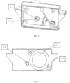
FIG. 2 is a schematic structural diagram of a roller driving assembly according to an embodiment; -
FIG. 3 is a schematic structural diagram of a roller driving assembly (without gears and rollers) according to an embodiment; and -
FIG. 4 is a schematic structural diagram of a back portion of a roller driving assembly according to an embodiment. -
- 1. Base;
- 2. Roller driving assembly;
- 2-1. Motor; 2-2. Motor shaft; 2-3. Housing; 2-4. First gear; 2-5. Second gear; 2-6. First roller; 2-7. Second roller; 2-8. Transmission shaft; 2-9. Torsion spring; 2-10. Limiting platform;
- 3. Toilet seat.
- The technical solutions of the embodiments of the present disclosure are clearly and completely described below with reference to the accompanying drawings in the embodiments of the present disclosure. Apparently, the described embodiments are merely some rather than all of the embodiments of the present disclosure. All other embodiments obtained by those of ordinary skill in the art based on the embodiments of the present disclosure without creative efforts shall fall within the protection scope of the present disclosure.
- In a specific embodiment, as shown in
FIG. 1 , an smart packaging toilet includesbase 1,toilet seat 3, and a plastic bag pull-down device. The plastic bag pull-down device includes tworoller driving assemblies 2. The plastic bag pull-down device is mounted on thebase 1, and the middle of thebase 1 is provided with a circular through hole for a plastic bag to pass through. The two roller driving assemblies 2 in the plastic bag pull-down device are mounted on two sides of the circular through hole and are fixed to thebase 1 by screws. - As shown in
FIGS. 2 to 4 , theroller driving assembly 2 includes motor 2-1, motor shaft 2-2, housing 2-3, first gear 2-4, second gear 2-5, first roller 2-6, and second roller 2-7. The motor 2-1 is mounted on an outer surface of the housing 2-3 and is connected to the first gear 2-4 through the motor shaft 2-2. The first gear 2-4 is connected to the first roller 2-6 and meshes with the second gear 2-5, and the second gear 2-5 is rotatably mounted on transmission shaft 2-8 inside the housing 2-3 and is connected to the second roller 2-7. Theroller driving assembly 2 further includes torsion spring 2-9 and limiting platform 2-10. The torsion spring 2-9 is sleeved on a fixed column in the housing 2-3, one end of the torsion spring 2-9 is limited to an inner wall of the housing 2-3, the other end of the torsion spring 2-9 presses the limiting platform 2-10, and the limiting platform 2-10 is connected to the transmission shaft 2-8. Each of the first roller 2-6 and the second roller 2-7 is wrapped with a rubber skin. Each motor 2-1 is direct-current deceleration motor 2-1. The tworoller driving assemblies 2 are mounted on two sides of a bottom of thetoilet seat 3 respectively. - In this embodiment, the
roller driving assemblies 2 on two sides are respectively driven by the motors 2-1, and each motor 2-1 drives the first gear 2-4 and the second gear 2-5 in the housing 2-3 to rotate, and then drives the first roller 2-6 and the second roller 2-7 to rotate, thereby driving a plastic bag to be pulled down and rotate. Middle parts of the first roller 2-6 and the second roller 2-7 are mounted corresponding to an inner ring of the toilet, so as to pull down and replace the plastic bag. - The first gear 2-4 is fixed to the motor shaft 2-2, and is connected to the first roller 2-6 in a D-shaped key connection mode. The second gear 2-5 and the second roller 2-7 are connected to the transmission shaft 2-8. Each of the first roller 2-6 and the second roller 2-7 is coated with a rubber skin to increase friction and provide certain deformation capacity. The second gear 2-5 is connected to the transmission shaft 2-8 is a pin connection mode, and the second gear 2-5 is fixed in a pin hole in the transmission shaft 2-8. The second roller 2-7 is connected to the transmission shaft 2-8 in a D-shaped key connection mode. The first gear 2-4 and the second gear 2-5 are in meshing transmission in the housing 2-3, and the first gear 2-4 drives the second gear 2-5 to drive the first roller 2-6 and the second roller 2-7 to rotate. The transmission shaft 2-8 is fixed in a slot hole of the housing 2-3, and the transmission shaft 2-8 is axially positioned by the limiting platform 2-10 and the torsion spring 2-9. The motor 2-1 is fixed into a hole of the housing 2-3 by a bolt. During operation of the plastic bag pull-down device, the two rollers need certain friction and squeezing to enable the plastic bag to be pulled down and replaced normally. However, if two shafts of the rollers are completely fixed, after use for a certain period of time, the rollers may be loosened due to wear and aging of rubber, resulting in the failure of a pull-down mechanism and the failure to operate normally. Moreover, after mounting, the positions of the two rubber rollers are attached and inseparable, so that it is very difficult to pull the plastic bag to between the rollers. Therefore, when the transmission shaft 2-8 is provided, a positioning hole of the transmission shaft 2-8 on the housing 2-3 is provided as a slot hole, so the transmission shaft 2-8 has a part of movable space, and the transmission shaft 2-8 can slide in a slot to a certain extent. In addition, the torsion spring 2-9 is arranged to press the transmission shaft 2-8, so that there is a certain pre-tightening force between the two rollers without loosening. When the plastic bag needs to be manually pressed to between the rollers for the first packaging, the movable shafts may be separated when squeezed by an external force, so that the two rollers are separated, which facilitates mounting.
- During practical operation, when a plastic bag is filled for the first time, a user needs to manually place the plastic bag to between the two rollers on two sides, and the plastic bag is pulled down by means of a squeezing force and friction between the rollers. Since the transmission shaft 2-8 for two second rollers 2-7 is fixed by the torsion spring 2-9, and the two rollers can be separated with a little force during use, so that the plastic bag is clamped to between the rollers. The rotation of the motors 2-1 on two sides drives the gears to rotate, and then drives the rollers to rotate to pull down the plastic bag.
- It should be noted that the above are merely preferred embodiments of the present disclosure, but are not intended to limit the present disclosure, and any modifications, equivalent replacements, improvements, and the like made within the spirit and principles of the present disclosure should fall within the protection scope of the present disclosure.
Claims (4)
- A plastic bag pull-down device for a smart packaging toilet, characterized by comprising two roller driving assemblies (2), wherein
the roller driving assembly (2) comprises a motor (2-1), a motor shaft (2-2), a housing (2-3), a first gear (2-4), a second gear (2-5), a first roller (2-6), and a second roller (2-7), wherein the motor (2-1) is mounted on an outer surface of the housing (2-3) and is connected to the first gear (2-4) through the motor shaft (2-2), the first gear (2-4) is connected to the first roller (2-6) and meshes with the second gear (2-5), and the second gear (2-5) is rotatably mounted on a transmission shaft (2-8) inside the housing (2-3) and is connected to the second roller (2-7). - The plastic bag pull-down device for the smart packaging toilet according to claim 1, characterized in that the roller driving assembly (2) further comprises a torsion spring (2-9) and a limiting platform (2-10), wherein
the torsion spring (2-9) is sleeved on a fixed column in the housing (2-3), one end of the torsion spring (2-9) is limited to an inner wall of the housing (2-3), the other end of the torsion spring (2-9) abuts against the limiting platform (2-10), and a circular hole in an edge of the limiting platform (2-10) is connected to the transmission shaft (2-8). - The plastic bag pull-down device for the smart packaging toilet according to claim 2, characterized in that each of the first roller (2-6) and the second roller (2-7) is wrapped with a rubber skin.
- A smart packaging toilet, comprising a base (1) and a toilet seat (3), characterized by further comprising the plastic bag pull-down device for the smart packaging toilet according to claim 1, wherein
the two roller driving assemblies (2) are mounted on two sides of a bottom of the toilet seat (3) respectively.
Applications Claiming Priority (1)
| Application Number | Priority Date | Filing Date | Title |
|---|---|---|---|
| CN202311161934.9A CN117163506A (en) | 2023-09-11 | 2023-09-11 | Plastic bag pull-down device for intelligent packaging toilet and intelligent toilet |
Publications (3)
| Publication Number | Publication Date |
|---|---|
| EP4520232A1 true EP4520232A1 (en) | 2025-03-12 |
| EP4520232C0 EP4520232C0 (en) | 2025-09-10 |
| EP4520232B1 EP4520232B1 (en) | 2025-09-10 |
Family
ID=88946694
Family Applications (1)
| Application Number | Title | Priority Date | Filing Date |
|---|---|---|---|
| EP24191918.2A Active EP4520232B1 (en) | 2023-09-11 | 2024-07-30 | Plastic bag pull-down device for smart packaging toilet and smart toilet with the device |
Country Status (4)
| Country | Link |
|---|---|
| US (1) | US20250082141A1 (en) |
| EP (1) | EP4520232B1 (en) |
| CN (1) | CN117163506A (en) |
| AU (1) | AU2024219634A1 (en) |
Cited By (1)
| Publication number | Priority date | Publication date | Assignee | Title |
|---|---|---|---|---|
| US20250281011A1 (en) * | 2024-03-05 | 2025-09-11 | Paul Chuang | Waterless toilet |
Citations (3)
| Publication number | Priority date | Publication date | Assignee | Title |
|---|---|---|---|---|
| US20060283153A1 (en) * | 2003-10-16 | 2006-12-21 | Kyoritsu Seiyaku Corporation | Packaging device and trash box |
| US20090255045A1 (en) * | 2008-04-15 | 2009-10-15 | Nihon Safety Co., Ltd. | Excretion packaging type portable tollet apparatus |
| CN110063682A (en) * | 2019-04-25 | 2019-07-30 | 深圳市乐享医疗科技有限公司 | A kind of separating anhydrous closestool of stool and urine |
Family Cites Families (13)
| Publication number | Priority date | Publication date | Assignee | Title |
|---|---|---|---|---|
| SE437118B (en) * | 1981-07-03 | 1985-02-11 | Stiftelsen Klintland | DEVICE FOR COLLECTION OF SOLID OR LIQUID WASTE |
| KR100642347B1 (en) * | 2003-05-20 | 2006-11-03 | 니혼 덴산 산쿄 가부시키가이샤 | Toilet lid opening and closing unit |
| AU2010263654C1 (en) * | 2009-06-22 | 2015-10-01 | Kyoritsu Seiyaku Corporation | Packaging device for waste containing device, and waste containing device |
| SG11201600503QA (en) * | 2013-08-06 | 2016-02-26 | Nihon Safety Co Ltd | Film sealing mechanism |
| KR101831755B1 (en) * | 2016-06-10 | 2018-02-26 | 노현길 | Toilet apparatus |
| CN207327818U (en) * | 2017-10-14 | 2018-05-08 | 北京紫瑞利印刷有限公司 | A kind of pressing device of offset press pressure roller |
| US11974703B2 (en) * | 2020-01-04 | 2024-05-07 | Kohler Co. | Liner toilet |
| CN213358223U (en) * | 2020-07-24 | 2021-06-04 | 陕西华萃路桥工程有限责任公司 | Road construction rolls and levels device |
| CN111920333A (en) * | 2020-08-24 | 2020-11-13 | 上海青宇科技有限公司 | A plastic bag pull-down replacement device for intelligently packing toilets |
| CN212650770U (en) * | 2020-08-24 | 2021-03-05 | 上海青宇科技有限公司 | Plastic bag pull-down replacing device for intelligent packaging pedestal pan |
| CN215457570U (en) * | 2021-04-26 | 2022-01-11 | 灵鹿智能科技(台州)有限公司 | Plastic bag leading-in structure |
| CN116331695B (en) * | 2023-01-31 | 2025-04-18 | 汇沅东(厦门)健康科技有限公司 | Garbage bag shrinking machine core, garbage bin and control |
| CN221317744U (en) * | 2023-09-11 | 2024-07-12 | 光子机器人(宁波)有限公司 | Plastic bag pull-down device for intelligent packaging toilet and intelligent packaging toilet |
-
2023
- 2023-09-11 CN CN202311161934.9A patent/CN117163506A/en active Pending
-
2024
- 2024-07-30 EP EP24191918.2A patent/EP4520232B1/en active Active
- 2024-09-11 US US18/882,665 patent/US20250082141A1/en active Pending
- 2024-09-11 AU AU2024219634A patent/AU2024219634A1/en active Pending
Patent Citations (3)
| Publication number | Priority date | Publication date | Assignee | Title |
|---|---|---|---|---|
| US20060283153A1 (en) * | 2003-10-16 | 2006-12-21 | Kyoritsu Seiyaku Corporation | Packaging device and trash box |
| US20090255045A1 (en) * | 2008-04-15 | 2009-10-15 | Nihon Safety Co., Ltd. | Excretion packaging type portable tollet apparatus |
| CN110063682A (en) * | 2019-04-25 | 2019-07-30 | 深圳市乐享医疗科技有限公司 | A kind of separating anhydrous closestool of stool and urine |
Cited By (2)
| Publication number | Priority date | Publication date | Assignee | Title |
|---|---|---|---|---|
| US20250281011A1 (en) * | 2024-03-05 | 2025-09-11 | Paul Chuang | Waterless toilet |
| US12502042B2 (en) * | 2024-03-05 | 2025-12-23 | Paul Chuang | Waterless toilet |
Also Published As
| Publication number | Publication date |
|---|---|
| AU2024219634A1 (en) | 2025-03-27 |
| EP4520232C0 (en) | 2025-09-10 |
| CN117163506A (en) | 2023-12-05 |
| US20250082141A1 (en) | 2025-03-13 |
| EP4520232B1 (en) | 2025-09-10 |
Similar Documents
| Publication | Publication Date | Title |
|---|---|---|
| EP4520232A1 (en) | Plastic bag pull-down device for smart packaging toilet and smart toilet with the device | |
| CN221317744U (en) | Plastic bag pull-down device for intelligent packaging toilet and intelligent packaging toilet | |
| EP0421986A1 (en) | A mop wringer, a mop wringing system and a roller. | |
| CN116688359A (en) | Automatic defibrillator | |
| CN209177053U (en) | A kind of metal material automatic packaging device | |
| CN110755736B (en) | Oral ulcer medicine coating device | |
| CN218660985U (en) | Film cold wave equipment | |
| CN217705234U (en) | Flip structure for printer | |
| CN214778607U (en) | Plate punching machine capable of feeding quickly | |
| CN111262116B (en) | Automatic computer network line connecting equipment | |
| CN216412001U (en) | Capacitance touch integrated machine | |
| CN215401990U (en) | Device for realizing continuous plastic bag separation discharging | |
| CN219566959U (en) | Film unreeling mechanism | |
| CN222398140U (en) | Automatic excrement sealing machine for films | |
| CN201095083Y (en) | Electric wrench | |
| CN214465949U (en) | Heavy-duty lightweight low-noise large-torsion brushless motor reduction gearbox assembly with brake | |
| CN219096208U (en) | Bonding device for middle sole film and PE film of paper diaper | |
| CN220876634U (en) | Paper towel machine goes out paper brake structure | |
| CN212749808U (en) | Low-resistance touch screen soft board assembling platform for 5G communication | |
| CN222018207U (en) | Automatic paper-out machine core | |
| CN112413339B (en) | Auxiliary device capable of automatically adjusting position of notebook computer display screen according to body position | |
| CN213826720U (en) | High-efficient numerical control punch press | |
| CN213891756U (en) | Soft PVC film printing process production line | |
| CN117885624B (en) | Automobile seat with massage structure | |
| CN220889920U (en) | Door control spring structure convenient to installation |
Legal Events
| Date | Code | Title | Description |
|---|---|---|---|
| PUAI | Public reference made under article 153(3) epc to a published international application that has entered the european phase |
Free format text: ORIGINAL CODE: 0009012 |
|
| STAA | Information on the status of an ep patent application or granted ep patent |
Free format text: STATUS: REQUEST FOR EXAMINATION WAS MADE |
|
| 17P | Request for examination filed |
Effective date: 20240730 |
|
| AK | Designated contracting states |
Kind code of ref document: A1 Designated state(s): AL AT BE BG CH CY CZ DE DK EE ES FI FR GB GR HR HU IE IS IT LI LT LU LV MC ME MK MT NL NO PL PT RO RS SE SI SK SM TR |
|
| GRAP | Despatch of communication of intention to grant a patent |
Free format text: ORIGINAL CODE: EPIDOSNIGR1 |
|
| STAA | Information on the status of an ep patent application or granted ep patent |
Free format text: STATUS: GRANT OF PATENT IS INTENDED |
|
| GRAJ | Information related to disapproval of communication of intention to grant by the applicant or resumption of examination proceedings by the epo deleted |
Free format text: ORIGINAL CODE: EPIDOSDIGR1 |
|
| STAA | Information on the status of an ep patent application or granted ep patent |
Free format text: STATUS: REQUEST FOR EXAMINATION WAS MADE |
|
| GRAP | Despatch of communication of intention to grant a patent |
Free format text: ORIGINAL CODE: EPIDOSNIGR1 |
|
| INTG | Intention to grant announced |
Effective date: 20250423 |
|
| STAA | Information on the status of an ep patent application or granted ep patent |
Free format text: STATUS: GRANT OF PATENT IS INTENDED |
|
| INTC | Intention to grant announced (deleted) | ||
| INTG | Intention to grant announced |
Effective date: 20250522 |
|
| RIN1 | Information on inventor provided before grant (corrected) |
Inventor name: XIAO, HEPING Inventor name: ZHANG, JIANG Inventor name: WANG, LEI |
|
| GRAS | Grant fee paid |
Free format text: ORIGINAL CODE: EPIDOSNIGR3 |
|
| GRAA | (expected) grant |
Free format text: ORIGINAL CODE: 0009210 |
|
| STAA | Information on the status of an ep patent application or granted ep patent |
Free format text: STATUS: THE PATENT HAS BEEN GRANTED |
|
| AK | Designated contracting states |
Kind code of ref document: B1 Designated state(s): AL AT BE BG CH CY CZ DE DK EE ES FI FR GB GR HR HU IE IS IT LI LT LU LV MC ME MK MT NL NO PL PT RO RS SE SI SK SM TR |
|
| REG | Reference to a national code |
Ref country code: GB Ref legal event code: FG4D |
|
| REG | Reference to a national code |
Ref country code: CH Ref legal event code: EP |
|
| REG | Reference to a national code |
Ref country code: DE Ref legal event code: R096 Ref document number: 602024000637 Country of ref document: DE |
|
| REG | Reference to a national code |
Ref country code: IE Ref legal event code: FG4D |
|
| U01 | Request for unitary effect filed |
Effective date: 20250911 |
|
| U07 | Unitary effect registered |
Designated state(s): AT BE BG DE DK EE FI FR IT LT LU LV MT NL PT RO SE SI Effective date: 20251016 |
|
| REG | Reference to a national code |
Ref country code: CH Ref legal event code: R17 Free format text: ST27 STATUS EVENT CODE: U-0-0-R10-R17 (AS PROVIDED BY THE NATIONAL OFFICE) Effective date: 20251205 |
|
| PG25 | Lapsed in a contracting state [announced via postgrant information from national office to epo] |
Ref country code: NO Free format text: LAPSE BECAUSE OF FAILURE TO SUBMIT A TRANSLATION OF THE DESCRIPTION OR TO PAY THE FEE WITHIN THE PRESCRIBED TIME-LIMIT Effective date: 20251210 |
|
| PG25 | Lapsed in a contracting state [announced via postgrant information from national office to epo] |
Ref country code: HR Free format text: LAPSE BECAUSE OF FAILURE TO SUBMIT A TRANSLATION OF THE DESCRIPTION OR TO PAY THE FEE WITHIN THE PRESCRIBED TIME-LIMIT Effective date: 20250910 |
|
| PG25 | Lapsed in a contracting state [announced via postgrant information from national office to epo] |
Ref country code: GR Free format text: LAPSE BECAUSE OF FAILURE TO SUBMIT A TRANSLATION OF THE DESCRIPTION OR TO PAY THE FEE WITHIN THE PRESCRIBED TIME-LIMIT Effective date: 20251211 |
|
| PG25 | Lapsed in a contracting state [announced via postgrant information from national office to epo] |
Ref country code: PL Free format text: LAPSE BECAUSE OF FAILURE TO SUBMIT A TRANSLATION OF THE DESCRIPTION OR TO PAY THE FEE WITHIN THE PRESCRIBED TIME-LIMIT Effective date: 20250910 |
|
| PG25 | Lapsed in a contracting state [announced via postgrant information from national office to epo] |
Ref country code: RS Free format text: LAPSE BECAUSE OF FAILURE TO SUBMIT A TRANSLATION OF THE DESCRIPTION OR TO PAY THE FEE WITHIN THE PRESCRIBED TIME-LIMIT Effective date: 20251210 |
|
| PG25 | Lapsed in a contracting state [announced via postgrant information from national office to epo] |
Ref country code: ES Free format text: LAPSE BECAUSE OF FAILURE TO SUBMIT A TRANSLATION OF THE DESCRIPTION OR TO PAY THE FEE WITHIN THE PRESCRIBED TIME-LIMIT Effective date: 20250910 |
|
| REG | Reference to a national code |
Ref country code: CH Ref legal event code: R18 Free format text: ST27 STATUS EVENT CODE: U-0-0-R10-R18 (AS PROVIDED BY THE NATIONAL OFFICE) Effective date: 20260331 |
|
| PG25 | Lapsed in a contracting state [announced via postgrant information from national office to epo] |
Ref country code: SM Free format text: LAPSE BECAUSE OF FAILURE TO SUBMIT A TRANSLATION OF THE DESCRIPTION OR TO PAY THE FEE WITHIN THE PRESCRIBED TIME-LIMIT Effective date: 20250910 |
|
| PG25 | Lapsed in a contracting state [announced via postgrant information from national office to epo] |
Ref country code: IS Free format text: LAPSE BECAUSE OF FAILURE TO SUBMIT A TRANSLATION OF THE DESCRIPTION OR TO PAY THE FEE WITHIN THE PRESCRIBED TIME-LIMIT Effective date: 20260110 |
|
| PG25 | Lapsed in a contracting state [announced via postgrant information from national office to epo] |
Ref country code: CZ Free format text: LAPSE BECAUSE OF FAILURE TO SUBMIT A TRANSLATION OF THE DESCRIPTION OR TO PAY THE FEE WITHIN THE PRESCRIBED TIME-LIMIT Effective date: 20250910 |
|
| PG25 | Lapsed in a contracting state [announced via postgrant information from national office to epo] |
Ref country code: SK Free format text: LAPSE BECAUSE OF FAILURE TO SUBMIT A TRANSLATION OF THE DESCRIPTION OR TO PAY THE FEE WITHIN THE PRESCRIBED TIME-LIMIT Effective date: 20250910 |