EP4520195A1 - Vapor generating device, and heater for vapor generating device - Google Patents
Vapor generating device, and heater for vapor generating device Download PDFInfo
- Publication number
- EP4520195A1 EP4520195A1 EP23818993.0A EP23818993A EP4520195A1 EP 4520195 A1 EP4520195 A1 EP 4520195A1 EP 23818993 A EP23818993 A EP 23818993A EP 4520195 A1 EP4520195 A1 EP 4520195A1
- Authority
- EP
- European Patent Office
- Prior art keywords
- heating element
- resistance heating
- generating device
- vapor generating
- sheet
- Prior art date
- Legal status (The legal status is an assumption and is not a legal conclusion. Google has not performed a legal analysis and makes no representation as to the accuracy of the status listed.)
- Pending
Links
Images





Classifications
-
- A—HUMAN NECESSITIES
- A24—TOBACCO; CIGARS; CIGARETTES; SIMULATED SMOKING DEVICES; SMOKERS' REQUISITES
- A24F—SMOKERS' REQUISITES; MATCH BOXES; SIMULATED SMOKING DEVICES
- A24F40/00—Electrically operated smoking devices; Component parts thereof; Manufacture thereof; Maintenance or testing thereof; Charging means specially adapted therefor
- A24F40/40—Constructional details, e.g. connection of cartridges and battery parts
- A24F40/46—Shape or structure of electric heating means
-
- A—HUMAN NECESSITIES
- A24—TOBACCO; CIGARS; CIGARETTES; SIMULATED SMOKING DEVICES; SMOKERS' REQUISITES
- A24F—SMOKERS' REQUISITES; MATCH BOXES; SIMULATED SMOKING DEVICES
- A24F40/00—Electrically operated smoking devices; Component parts thereof; Manufacture thereof; Maintenance or testing thereof; Charging means specially adapted therefor
- A24F40/50—Control or monitoring
- A24F40/57—Temperature control
-
- A—HUMAN NECESSITIES
- A24—TOBACCO; CIGARS; CIGARETTES; SIMULATED SMOKING DEVICES; SMOKERS' REQUISITES
- A24F—SMOKERS' REQUISITES; MATCH BOXES; SIMULATED SMOKING DEVICES
- A24F40/00—Electrically operated smoking devices; Component parts thereof; Manufacture thereof; Maintenance or testing thereof; Charging means specially adapted therefor
- A24F40/20—Devices using solid inhalable precursors
-
- A—HUMAN NECESSITIES
- A24—TOBACCO; CIGARS; CIGARETTES; SIMULATED SMOKING DEVICES; SMOKERS' REQUISITES
- A24F—SMOKERS' REQUISITES; MATCH BOXES; SIMULATED SMOKING DEVICES
- A24F40/00—Electrically operated smoking devices; Component parts thereof; Manufacture thereof; Maintenance or testing thereof; Charging means specially adapted therefor
- A24F40/40—Constructional details, e.g. connection of cartridges and battery parts
- A24F40/46—Shape or structure of electric heating means
- A24F40/465—Shape or structure of electric heating means specially adapted for induction heating
Definitions
- Embodiments of this application relate to the field of heat-not-burn vapor generating technologies, and in particular, to a vapor generating device and a heater for a vapor generating device.
- Tobacco products for example, cigarettes and cigars
- tobacco-burning products by manufacturing products that release compounds without burning.
- the products is a heating device that releases compounds by heating rather than burning a material.
- the material may be an aerosol generating product including tobacco or other non-tobacco products, and these non-tobacco products may or may not include nicotine.
- a heating element is arranged around a heat dissipation component of a honeycomb structure, and the heat dissipation component of the honeycomb structure is heated by the heating element, so that air is heated to form a hot airflow when passing through a honeycomb hole in the heat dissipation component. Then, the tobacco or the other non-tobacco products are heated through the hot airflow.
- An embodiment of this application provides a vapor generating device, configured to heat an aerosol generating product to generate an aerosol.
- the vapor generating device includes: at least one resistance heating element formed by winding or bending a sheet made of a resistive metal or alloy, where the at least one resistance heating element includes at least two wound or bent resistance heating layers; and during inhalation, air at least partially passes between the at least two resistance heating layers, and is heated between the at least two resistance heating layers and then outputted to the aerosol generating product.
- the vapor generating device further includes: a holding element, at least partially surrounding or holding the at least one resistance heating element.
- the at least one resistance heating element is accommodated in the holding element; and the holding element includes:
- the vapor generating device further includes:
- the vapor generating device further includes: a first wire and a second wire, configured to supply power to the resistance heating element.
- the resistance heating element is in a cylindrical shape formed by winding the sheet; and the first wire is at least partially arranged inside the resistance heating element, and the second wire is arranged outside the resistance heating element.
- the resistance heating element is formed by winding the sheet around the first wire as an axis; and a diameter of the first wire is greater than a diameter of the second wire.
- the resistance heating element is formed by winding the sheet around the first wire as an axis; and a diameter of the first wire ranges from 0.1 mm to 1.5 mm.
- the vapor generating device further includes:
- the vapor generating device further includes:
- the vapor generating device further includes:
- the vapor generating device further includes: a porous body material, located between adjacent resistance heating layers.
- the sheet is continuous.
- the at least two resistance heating layers are connected in series.
- the resistance heating element is constructed by spirally winding the sheet.
- the resistance heating element is constructed by reciprocally bending the sheet.
- the resistance heating element has a central axis along a longitudinal direction; and the resistance heating element has symmetry about the central axis, and the resistance heating element is rotationally symmetrical by 180 degrees around the central axis.
- the resistance heating element includes a plurality of conductive units formed on the at least two resistance heating layers.
- the plurality of conductive units are connected in series or in parallel.
- the plurality of conductive units are sequentially connected end to end.
- the sheet is provided with several holes, hollows, or slits, to enable the sheet to form a grid pattern.
- the sheet includes a foil layer made of a resistive metal or alloy.
- Another embodiment of this application further provides a heater of a vapor generating device, including:
- Another embodiment of this application further provides a vapor generating device, configured to heat an aerosol generating product to generate an aerosol.
- the vapor generating device includes:
- An embodiment of this application provides a vapor generating device 100 heating rather than burning an aerosol generating product 1000, such as a cigarette, to volatilize or release at least one component of the aerosol generating product 1000 to form an aerosol for inhalation, as shown in FIG. 1 .
- the aerosol generating product 1000 is preferably a tobacco-containing material with volatile compounds released from a substrate during heating; or may be a non-tobacco material that can be suitable for electric heating smoke production after being heated.
- the aerosol generating product 1000 is preferably a solid substrate, which may include one or more of powders, particles, shreds, strips, or flakes of one or more of a vanilla leaf, a tobacco leaf, homogenized tobacco, and expanded tobacco.
- the solid substrate may include additional tobacco or non-tobacco volatile flavor compounds, so as to be released when the substrate is heated.
- a part of the aerosol generating product 1000 is exposed outside the vapor generating device 100, for example, a filter, which is advantageous for inhalation by a user.
- FIG. 1 An overall shape of the device is generally constructed as a flat cylinder.
- External components of the vapor generating device 100 include: a housing 10, where an interior of the housing is of a hollow structure, to form assembly space that can be used for necessary functional components such as an electronic component and a heating component; and the housing 10 includes a proximal end 110 and a distal end 120 opposite to each other along a length direction.
- the vapor generating device 100 further includes:
- the wall 12 is in a tubular shape.
- the wall 12 is non-detachable or fixed and non-movable in the housing 10.
- the vapor generating device 100 further includes:
- the vapor generating device 100 further includes: a heater 30, at least partially heating air passing through the heater 30 during inhalation, and heating the aerosol generating product 1000 by heated hot air.
- the heater 30 is positioned between the air channel 150 and the chamber; and the heater 30 is positioned between the wall 12 and the air channel 150. In this way, the heater 30 heats air entering the chamber through the air channel 150 during inhalation, and then outputs the heated hot air to the aerosol generating product 1000.
- At least one support element 40 is arranged between the heater 30 and the wall 12.
- the at least one support element 40 is configured to provide support between the wall 12 and the heater 30; and the at least one support element 40 is further configured to provide holding between the wall 12 and the heater 30, so that a spacing greater than 1 mm is held between the heater 30 and the chamber defined by the wall 12.
- the heater 30 is not in contact with the aerosol generating product 1000 received in the chamber, and the aerosol generating product 1000 can be heated only by the hot air.
- At least one flexible sealing element 40 is arranged between the heater 30 and the wall 12.
- the flexible sealing element 40 is made of a flexible material such as silicone or a thermoplastic elastomer.
- the at least one sealing element 40 is configured to provide hermetic sealing between the heater 30 and the wall 12, to maximally prevent the hot air outputted by the heater 30 from escaping between the heater 30 and the wall 12.
- the support element 40 or the sealing element 40 is in an annular shape at least partially surrounding the heater 30/the wall 12.
- the heater 30 includes: a first end 311 and a second end 312 that face away from each other, where the first end 311 is close to and faces the chamber/the aerosol generating product 1000, and the second end 312 is close to and faces the air channel 150.
- the air enters the heater 30 from the second end 312 to be heated, and then is outputted from the first end 311 to the chamber/the aerosol generating product 1000, as shown by arrows R12 in FIG. 2 and FIG. 3 .
- the heater 30 includes at least one or more airflow channels located between the first end 311 and the second end 312, so that the air passes from the second end 312 to the first end 311.
- the heater 30 includes: a holding element 310 and a heating element 320.
- the holding element 310 is substantially in a tubular shape; and defining the first end 311 and the second end 312 of the heater 30, where the holding element 310 includes an inner cavity, and the inner cavity extends between the first end 311 and the second end 312.
- the inner cavity has an opening at the first end 311, to output heated air in the inner cavity to the chamber/the aerosol generating product 1000; and the inner cavity has an opening at the second end 312 for air to enter the inner cavity.
- an inner diameter of the holding element 310 ranges from 5.0 mm to 8.0 mm; a distance between an inner surface and an outer surface of the tubular holding element 310 (or a wall thickness of the holding element 310) ranges from 1 mm to 3 mm; and the holding element 310 is preferably made of a rigid insulation material, such as ceramic, glass, PEEK, organic polymer resin, or surface insulation metal.
- the heating element 320 is located in the holding element 310, and at least partially held by the holding element 310.
- the heating element 320 is configured to heat the air passing from the second end 312 to the first end 311 during inhalation. As shown in FIG. 1 and FIG. 2 , the heating element 320 is accommodated and held in the inner cavity of the holding element 310.
- the heater 30 includes:
- a hollow region is further provided between the inner surface and the outer surface of the holding element 310, and a pressure of the hollow region is lower than a pressure of the external atmosphere, so that the hollow region of the holding element 310 forms thermal insulation vacuum space.
- the pressure of the hollow region between the inner surface and the outer surface of the holding element 310 ranges from 0.1 mbar to 0.001 mbar.
- the heating element 320 is supported and fixed in the holding element 310 through some support components or structures located in the holding element 310. In this case, the heating element 320 is not in contact with the inner surface of the holding element 310, which is advantageous to prevent heat of the heating element 33 from being dissipated through the holding element 310.
- the heating element 320 is a resistance heating element.
- the heating element 320 in this embodiment is in a cylindrical or tubular shape obtained by winding a sheet 3210 including a resistive metal or alloy.
- the wound heating element 320 includes at least two wound heating layers 321.
- the resistive metal or alloy includes at least one of nickel, cobalt, zirconium, titanium, nickel alloy, cobalt alloy, zirconium alloy, titanium alloy, nickel-chromium alloy, nickel-iron alloy, iron-chromium alloy, iron-chromium-aluminum alloy, titanium alloy, iron-manganese-aluminum-based alloy, or stainless steel.
- the heating element 320 obtained by spirally winding the sheet 3210 is arranged to have an extension length approximately ranging from 10 mm to 40 mm; and the heating element 320 obtained by spirally winding the sheet 3210 has an outer diameter approximately ranging from 5 mm to 8 mm.
- At least one side surface of the sheet 3210 made of the resistive metal or alloy has an insulation layer or an insulation material, to provide insulation to prevent a contact short circuit between adjacent wound heating layers 321 during winding.
- the insulation layer or the insulation material is, for example, a surface oxidation layer formed by oxidizing a surface of the sheet 3210 made of the resistive metal or alloy, or a coated high-temperature-resistant inorganic glue/glaze.
- the heating element 320 is configured to generate heat by generating Joule heat when a direct current flows through the heating element 320.
- the heating element 320 formed by winding is formed by winding the sheet 3210 made of an inductive metal or alloy.
- the sheet 3210 made of the inductive metal or alloy includes foil made of an inductive metal or alloy such as nickel-iron alloy or iron-aluminum alloy. In this case, the heating element 320 can be penetrated by a changing magnetic field to generate heat.
- an induction coil (not shown in the figure) may be arranged on the outer surface of the holding element 310, and the induction coil surrounds and is held outside the holding element 310; and the induction coil is configured to generally generate the changing magnetic field to induce the heating element 320 wound by the sheet 3210 made of the inductive metal or alloy to generate heat, thereby heating the air.
- a spacing or channel 322 exists between adjacent heating layers 321 of the heating element 320.
- an airflow channel passing through the heating element 320/the heater 30 is at least partially defined by the spacing or channel 322.
- the spacing or channel 322 is obtained by spirally winding the sheet 3210.
- the spacing or channel 322 between adjacent heating layers 321 ranges from 0.5 mm to 3 mm in some embodiments.
- the heating element 320 further includes: a porous body material, located in the spacing or channel 322; or a porous body material, located between adjacent heating layers 321.
- the porous body material is, for example, a porous ceramic body, porous diatomite, or porous glass. During inhalation, the air can pass through the porous body material to be heated and outputted.
- the porous body material may be further configured to store heat, to absorb and store heat dissipated by the heating layer 321 during non-inhalation.
- a porosity of the porous body material is greater than 60%; and an average microporous pore size of the porous body material is greater than 100 ⁇ m, for example, ranges from 150 ⁇ m to 500 ⁇ m.
- the sheet 3210 wound to form the heating element 320 is foil made of a resistive metal or alloy.
- the foil made of a resistive metal or alloy has a thickness approximately ranging from 0.5 ⁇ m to 200 ⁇ m; and more preferably, has a thickness approximately ranging from 10 ⁇ m to 30 ⁇ m.
- the sheet 3210 wound to form the heating element 320 is a composite sheet including at least two layers.
- the sheet 3210 wound to form the heating element 320 includes:
- the stress compensation layer 3230 is hard, such as glaze, glass, or ceramic, to improve the strength or toughness of the sheet, to prevent the sheet 3210 from being cracked or broken during winding.
- the stress compensation layer 3230 is a flexible layer.
- the stress compensation layer 3230 is made of a flexible polymer material such as polyimide, free polypropylene, or polyethylene.
- the stress compensation layer 3230 has a same thickness as a metal or alloy layer; and the stress compensation layer 3230 is formed on at least one side surface of the foil layer 3220 made of a metal or alloy by coating, deposition, or the like.
- the sheet 3210 wound to form the heating element 320 further includes: a porous body material layer 3240.
- a porous body material layer 3240 By pre-combining or preparing the foregoing porous body material in a form of a layer on the foil layer 3220 made of a metal or alloy, the porous body material layer 3240 may be filled between the heating layers 321 in the heating element 320 formed through winding. It is more convenient compared with filling the porous body material in the spacing or channel 322 after winding.
- the sheet 3210 wound to form the heating element 320 further includes: a transition layer 3240, for example, a waxy layer, an organic slurry, or a resin.
- the transition layer can provide insulation before the adjacent foil layers 3220 made of a metal or alloy of the sheet 3210 during winding.
- the transition layer 3240 may be volatilized, pyrolized, or melted by causing the heating element 320 to generate heat after winding. In this way, a position originally occupied by the transition layer 3240 forms space of the spacing or channel 322 after winding. This is more convenient in preparation.
- the stress compensation layer 3230 and the transition layer 3240/the porous body material layer 3240 are respectively arranged on two sides of the foil layer 3220 made of a metal or alloy.
- the compensation layer 3230 and the transition layer 3240/the porous body material layer 3240 are located on a same side of the foil layer 3220 made of a metal or alloy.
- the heating element 320 further includes: a first wire 341 and a second wire 342, connected to the heating element 320 to supply power to the heating element 320.
- the first wire 341 is located on one side of the sheet 3210, and the second wire 342 is located on the other side of the sheet 3210; and after winding, the first wire 341 is wound inside the heating element 320, and the second wire 342 is substantially located outside the heating element 320.
- the first wire 341 is connected to an innermost heating layer 321 of the heating element 320, and the second wire 342 is connected to an outermost heating layer 321 of the heating element 320.
- a diameter of the first wire 341 and a diameter of the second wire 342 may approximately range from 0.1 mm to 0.3 mm.
- the first wire 341 and the second wire 342 are both made of a material with low resistivity, such as gold, silver, copper, nickel, or an alloy containing the same.
- a diameter of the first wire 341 is greater than a diameter of the second wire 342.
- the diameter of the second wire 342 may approximately range from 0.1 mm to 0.3 mm; and the diameter of the first wire 341 ranges from 0.5 mm to 1.5 mm, so that the strength of the first wire 341 is greater than the strength of a conventional copper wire and silver-plated nickel wire.
- the heating element 320 obtained by winding the sheet 3210 around the first wire 341 as an axis is supported by the thicker first wire 341, and has greater strength.
- the heating element 320 approximately includes 2 to 20 windings.
- the heating element 320 is obtained by spirally winding the sheet 3210 from inside to outside. Counting from the innermost first wire 341, each winding of 360 degrees of the sheet around the first wire 341 is considered as one winding, and one heating layer 321 is formed.
- the resistance heating element 320 includes five wound resistance heating layers 321.
- FIG. 5 and FIG. 6 are schematic diagrams of a heater 30 according to another variant embodiment.
- the heater 30 includes:
- the holding element 310a at least partially provides mounting and holding for the heating element 320a by holding the exposed part 351a.
- a first wire 341a is welded to the exposed part 351a, and then is indirectly conducted with an end of the heating element 320a; and a second wire 342a is welded to the other side of an outermost surface of the wound heating element 320a, and then serves as a positive/negative electrode together with the first wire 341a to guide a current on the heating element 320a.
- FIG. 7 is a top view or a schematic cross-sectional view of a heater 30 according to another variant embodiment.
- the heater 30 includes:
- the heating element 320b formed by reciprocally bending the sheet is substantially in a cylindrical or tubular shape.
- the heating element 320b is symmetrical along a central axis passing through a center point O.
- a cross-sectional shape of the heating element 320b obtained by reciprocally bending the sheet is symmetrical about the central axis passing through the center point O by rotating by 180 degrees.
- the heating element 320b obtained by reciprocally bending the sheet includes a first end portion and a second end portion opposite to each other along the radial direction.
- a first wire 341b is welded to or connected to the first end portion
- a second wire 342b is welded to or connected to the second end portion.
- both the first end portion and the second end portion are located or exposed outside the heating element 320b, which is very convenient for welding or connecting a power supply wire during preparation.
- a sheet 3210c configured to be wound or bent to form the heating element 320/320a/320b is provided with several holes or hollows 3211c, to increase a resistance value of the heating element 320/320a/320b.
- the holes or hollows 3211c are arranged in a regular matrix; and the holes or hollows 3211c are formed by etching or the like to be in a circular shape.
- the holes or hollows 3211c may be square, polygonal, or in other shapes, so that the sheet 3210c presents a grid pattern.
- FIG. 9 is a schematic diagram of a sheet 3210d before winding or bending according to another variant embodiment.
- a first wire 341b and a second wire 342b are arranged on two side ends of the sheet 3210d along a length direction; and the sheet 3210d is sequentially arranged with a first side portion 3211d, a central portion 3213d, and a second side portion 3212d along the length direction.
- an extension length of the central portion 3213d is greater than an extension length of the first side portion 3211d and an extension length of the second side portion 3212d, and a width d2 of the central portion 3213d is less than a width d1 of the first side portion 3211d and the second side portion 3212d. Further, through the foregoing shape arrangement, the resistance of the sheet 3210d is increased, and heat generation is concentrated as much as possible in the central portion 3213d.
- the first side portion 3211d and the second side portion 3212d are configured to be wound and connected to wires for power supply.
- FIG. 10 is a schematic diagram of a sheet 3210e before winding or bending according to another variant embodiment.
- the sheet 3210e is substantially in a rectangular shape, and several slits or hollows 3211e and several slits or hollows 3212e are formed on the sheet 3210e by etching or cutting, to reduce an area of the sheet 3210e during power supply, thereby improving the resistance of the heating element 320/320a/320b formed after winding or bending.
- the slits or hollows 3211e and/or the slits or hollows 3212e are in an elongated strip shape extending along a width direction of the sheet 3210e.
- the several slits or hollows 3211e and the several slits or hollows 3212e are provided alternately/at intervals along a length direction of the sheet 3210g.
- the slits or hollows 3211e and the slits or hollows 3212e are staggered along the length direction of the sheet 3210e. Specifically, in FIG. 10 , the slit or hollow 3211e is located at a central position along the width direction of the sheet 3210e, and the slit or hollow 3212e is located at an edge position along the width direction of the sheet 3210e.
- a first wire 341e and a second wire 342e are further arranged on two sides of the sheet 3210e along the length direction to supply power.
- a circuitous current i flowing through the heating element 320/320a/320b in FIG. 10 is formed by combining the first wire 341e and the second wire 342e with the slits or hollows 3211e and the slits or hollows 3212e that are arranged in a staggered manner.
- a surface of at least one side of the sheet 3210e is coated with an insulation and support material such as glaze or ceramic, to provide insulation or support between folded resistance heating layers.
- a folded heating element is obtained by folding the sheet 3210e along a broken line n1 and/or a broken line n2 defined by the slit or hollow 3211e and/or the slit or hollow 3212e.
- FIG. 11 is a schematic diagram of a heating element 320f formed by reciprocally folding a sheet.
- the heating element 320f is formed by reciprocally folding the sheet 3210e or a similar material.
- a length L1 of the heating element 320f formed by folding approximately ranges from 10 mm to 40 mm; a width L2 of the heating element 320f formed by folding approximately ranges from 5 mm to 8 mm; and a thickness L3 of the heating element 320f formed by folding approximately ranges from 5 mm to 8 mm.
- a cross-sectional shape of the heating element 320f formed by reciprocally folding the sheet may be substantially rectangular.
- the reciprocally folded heating element 320f includes two or more heating layers 321f; and a spacing or channel 322f for air to pass through is formed between adjacent heating layers 321f.
- a porous body material is filled in the spacing or channel 322f.
- the spacing or channel 322f formed in the reciprocally folded heating element 320f includes:
- the first spacing or channel 3221f and the second spacing or channel 3222f are alternately provided along the thickness direction.
- a sheet 3210g is shaped or constructed with a plurality of conductive units 3212g connected in series.
- the conductive unit 3212g extends along a width direction of the sheet 3210g; the sheet 3210g is provided with a slit or hollow 3211g and a slit or hollow 3214g extending along the width direction of the sheet 3210g; and a width of the slit or hollow 3214g is greater than a width of the slit or hollow 3211g.
- the width of the slit or hollow 3211g/the slit or hollow 3214g approximately ranges from 0.2 mm to 1.0 mm, and a length of the slit or hollow 3211g/the slit or hollow 3214g approximately ranges from 8 mm to 35 mm.
- the slit or hollow 3211g terminates at a lower end portion of the sheet 3210g along the width direction, and the slit or hollow 3214g avoids an upper end portion of the sheet 3210g along the width direction.
- the slit or hollow 3211g and the slit or hollow 3214g are alternately provided at intervals along the length direction of the sheet 3110g. Further, the slit or hollow 3211g and the slit or hollow 3214g define the plurality of conductive elements 3212g connected in series.
- the plurality of conductive units 3212g connected in series and jointly defined by the slit or hollow 3211g and the slit or hollow 3214g are sequentially connected end to end.
- the sheet 3210 configured to be wound or folded to form the heating element 320 includes:
- the heating coating or track is formed by a paste of a metal or alloy.
- the heating coating or track is in a shape that is circuitous or bends and extends on the substrate.
- the heater 30 further includes: a first temperature sensor, for example, a PT1000 or a J-type thermocouple.
- the first temperature sensor is arranged close to the first end 311 of the holding element 310.
- the first temperature sensor is configured to sense a temperature outputted by the heater 30 to the chamber or the aerosol generating product 1000.
- the circuit board 140 controls, based on a sensing result of the first temperature sensor, a power provided to the heater 30, so that the temperature of the hot air outputted to the aerosol generating product 1000 is maintained at a target temperature.
- the heater 30 further includes: a second temperature sensor, combined on the heating element 320/320a/320b, to sense a temperature of the heating element 320/320a/320b. Further, the circuit board 140 controls, based on a sensing result of the second temperature sensor, the power provided to the heater 30, so that the temperature of the hot air outputted to the aerosol generating product 1000 is maintained at the target temperature.
- a second temperature sensor combined on the heating element 320/320a/320b, to sense a temperature of the heating element 320/320a/320b.
- the circuit board 140 controls, based on a sensing result of the second temperature sensor, the power provided to the heater 30, so that the temperature of the hot air outputted to the aerosol generating product 1000 is maintained at the target temperature.
- FIG. 14 is a schematic diagram of a vapor generating device 100 according to another embodiment.
- the vapor generating device 100 includes a first heater 30k and a second heater 60k that are sequentially arranged at intervals.
- the second heater 60k is closer to the chamber/the aerosol generating product 1000 than the first heater 30k.
- the air sequentially passes through the first heater 30k and the second heater 60k and is heated to a predetermined temperature, and then is outputted to the chamber/the aerosol generating product 1000.
- the second heater 60k and the first heater 30k are separated by an isolator 50k; and the isolator 50k is further configured to provide sealing at edges of the second heater 60k and the first heater 30k.
- the first heater 30k is located upstream of the second heater 60k, and the second heater 60k is not in contact with the first heater 30k.
- the first heater 30k is configured to heat the air to a first predetermined temperature and then output the air to the second heater 60k, and the second heater 60 further heats the air to a second predetermined temperature and then outputs the air to the chamber/the aerosol generating product 1000.
- the second predetermined temperature is higher than the first predetermined temperature.
- An extension length of the first heater 30k is greater than an extension length of the second heater 60.
- the vapor generating device 100 includes only two heaters. Alternatively, in some other embodiments, the vapor generating device 100 may include more, for example, three, four, or five heaters.
- a cross-sectional area of a channel through which the air passes in the first heater 30k is greater than a cross-sectional area of a channel through which the air passes in the second heater 60.
- a spacing between heating layers of a heating element in the first heater 30k may be greater than a spacing between heating layers of a heating element in the second heater 60.
- FIG. 15 is a schematic diagram of a vapor generating device 100 according to another embodiment.
- the vapor generating device 100 includes a heater 30i.
- the heater 30i includes: a holding element 310i, and a first heating element 330i and a second heating element 320i sequentially arranged at an interval in the holding element 310i.
- the second heating element 320i is closer to the chamber/the aerosol generating product 1000 than the first heating element 330i.
- the air sequentially passes through the first heating element 330i and the second heating element 320i and is heated to a predetermined temperature, and then is outputted to the chamber/the aerosol generating product 1000.
- the first heating element 330i and the second heating element 320i are separated from each other.
- the first heating element 330i is located upstream of the second heating element 320i, and the second heating element 320i is not in contact with the first heating element 330i.
- the first heating element 330i is configured to heat the air to a first predetermined temperature and then output the air to the second heating element 320i, and the second heating element 320i further heats the air to a second predetermined temperature and then outputs the air to the chamber/the aerosol generating product 1000.
- the second predetermined temperature is higher than the first predetermined temperature.
- the vapor generating device 100 includes only two heating elements. Alternatively, in some other embodiments, the vapor generating device 100 may include more, for example, three, four, or five heating elements.
- the first heating element 330i and the second heating element 320i are independently connected to a circuit board 140i, and then are independently driven by the circuit board 140i to perform heating. In addition, in some other embodiments, the first heating element 330i and the second heating element 320i perform heating simultaneously. In addition, in some other embodiments, the first heating element 330i and the second heating element 320i do not perform heating simultaneously.
- first heating element 330i and the second heating element 320i may be alternately activated.
Landscapes
- Resistance Heating (AREA)
Abstract
Description
- This application claims priority to
Chinese Application No. 202210657284.6, filed with the China National Intellectual Property Administration on June 10, 2022 - Embodiments of this application relate to the field of heat-not-burn vapor generating technologies, and in particular, to a vapor generating device and a heater for a vapor generating device.
- Tobacco products (for example, cigarettes and cigars) burn tobacco during use to produce tobacco smoke. Attempts are made to replace these tobacco-burning products by manufacturing products that release compounds without burning.
- An example of the products is a heating device that releases compounds by heating rather than burning a material. For example, the material may be an aerosol generating product including tobacco or other non-tobacco products, and these non-tobacco products may or may not include nicotine. In an existing heating device, a heating element is arranged around a heat dissipation component of a honeycomb structure, and the heat dissipation component of the honeycomb structure is heated by the heating element, so that air is heated to form a hot airflow when passing through a honeycomb hole in the heat dissipation component. Then, the tobacco or the other non-tobacco products are heated through the hot airflow.
- An embodiment of this application provides a vapor generating device, configured to heat an aerosol generating product to generate an aerosol. The vapor generating device includes:
at least one resistance heating element formed by winding or bending a sheet made of a resistive metal or alloy, where the at least one resistance heating element includes at least two wound or bent resistance heating layers; and during inhalation, air at least partially passes between the at least two resistance heating layers, and is heated between the at least two resistance heating layers and then outputted to the aerosol generating product. - In some embodiments, the vapor generating device further includes:
a holding element, at least partially surrounding or holding the at least one resistance heating element. - In some embodiments, the at least one resistance heating element is accommodated in the holding element; and the holding element includes:
- an air inlet for air to enter; and
- an air outlet for outputting the heated air to the aerosol generating product.
- In some embodiments, the vapor generating device further includes:
- a temperature sensor, combined with the at least one resistance heating element to sense a temperature of the at least one resistance heating element; and/or
- a temperature sensor, located at the air outlet to sense a temperature of the air outputted by the air outlet.
- In some embodiments, the vapor generating device further includes:
a first wire and a second wire, configured to supply power to the resistance heating element. - In some embodiments, the resistance heating element is in a cylindrical shape formed by winding the sheet; and
the first wire is at least partially arranged inside the resistance heating element, and the second wire is arranged outside the resistance heating element. - In some embodiments, the resistance heating element is formed by winding the sheet around the first wire as an axis; and a diameter of the first wire is greater than a diameter of the second wire.
- In some embodiments, the resistance heating element is formed by winding the sheet around the first wire as an axis; and a diameter of the first wire ranges from 0.1 mm to 1.5 mm.
- In some embodiments, the vapor generating device further includes:
- a conductive base body, where the resistance heating element is formed by winding the sheet around the conductive base body as an axis; the conductive base body is electrically conductive to the resistance heating element;
- the first wire is indirectly conducted with the resistance heating element by being connected to the conductive base body; and
- the second wire is directly connected to and conducted with the resistance heating element.
- In some embodiments, the vapor generating device further includes:
- a base body, where the resistance heating element is formed by winding the sheet around the base body as an axis; the base body includes an exposed part extending out of the resistance heating element; and
- the holding element at least partially holds the resistance heating element by holding the exposed part.
- In some embodiments, the vapor generating device further includes:
- a chamber, configured to receive at least part of the aerosol generating product; and
- an air-permeable blocking element, located between the chamber and the at least one resistance heating element, and configured to prevent an aerosol condensate or residues from the aerosol generating product from falling into or entering the at least one resistance heating element.
- In some embodiments, the vapor generating device further includes:
a porous body material, located between adjacent resistance heating layers. - In some embodiments, the sheet is continuous.
- In some embodiments, the at least two resistance heating layers are connected in series.
- In some embodiments, the resistance heating element is constructed by spirally winding the sheet.
- In some embodiments, the resistance heating element is constructed by reciprocally bending the sheet.
- In some embodiments, the resistance heating element has a central axis along a longitudinal direction; and
the resistance heating element has symmetry about the central axis, and the resistance heating element is rotationally symmetrical by 180 degrees around the central axis. - In some embodiments, the resistance heating element includes a plurality of conductive units formed on the at least two resistance heating layers.
- In some embodiments, the plurality of conductive units are connected in series or in parallel.
- In some embodiments, the plurality of conductive units are sequentially connected end to end.
- In some embodiments, the sheet is provided with several holes, hollows, or slits, to enable the sheet to form a grid pattern.
- In some embodiments, the sheet includes a foil layer made of a resistive metal or alloy.
- Another embodiment of this application further provides a heater of a vapor generating device, including:
- a holding element, including an inner cavity; and
- at least one heating element, located in the inner cavity to heat air passing through the inner cavity, where the at least one heating element includes: at least two resistance heating layers formed by winding or bending a sheet made of a resistive metal or alloy; and during use, the air at least partially passes between the at least two resistance heating layers and is heated between the at least two resistance heating layers.
- Another embodiment of this application further provides a vapor generating device, configured to heat an aerosol generating product to generate an aerosol. The vapor generating device includes:
- at least one induction heating element, including at least two induction heating layers formed by winding or bending a sheet made of an inductive metal or alloy, where during inhalation, air at least partially passes between the at least two induction heating layers, and is heated between the at least two induction heating layers and then outputted to the aerosol generating product; and
- a magnetic field generator, configured to generate a changing magnetic field, where the induction heating element is penetrated by the changing magnetic field to generate heat.
- One or more embodiments are exemplarily described with reference to the corresponding figures in the accompanying drawings, and the exemplary descriptions are not to be construed as limiting the embodiments. Elements in the accompanying drawings that have same reference numerals are represented as similar elements, and unless otherwise particularly stated, the figures in the accompanying drawings are not drawn to scale.
-
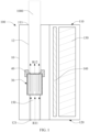
FIG. 1 is a schematic diagram of a vapor generating device according to an embodiment; -
FIG. 2 is a schematic structural diagram of a heater inFIG. 1 ; -
FIG. 3 is a schematic exploded view of parts of the heater inFIG. 2 ; -
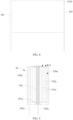
FIG. 4 is a schematic diagram of a sheet of a heating element inFIG. 3 before winding; -
FIG. 5 is a schematic structural diagram of a heater according to another embodiment; -
FIG. 6 is a schematic diagram of winding a sheet on a rod-shaped conductive base body inFIG. 5 ; -
FIG. 7 is a top view or a cross-sectional view of a heater according to another embodiment; -
FIG. 8 is a schematic diagram of a sheet according to another embodiment; -
FIG. 9 is a schematic diagram of a sheet according to another embodiment; -
FIG. 10 is a schematic diagram of a sheet according to another embodiment; -
FIG. 11 is a schematic diagram of a heating element according to another embodiment; -
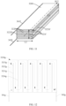
FIG. 12 is a schematic diagram of a sheet before folding according to another embodiment; -
FIG. 13 is a schematic diagram of a sheet according to an embodiment; -
FIG. 14 is a schematic diagram of a vapor generating device according to another embodiment; and -
FIG. 15 is a schematic diagram of a vapor generating device according to another embodiment. - For ease of understanding this application, this application is described below in more detail with reference to accompanying drawings and specific implementations.
- An embodiment of this application provides a
vapor generating device 100 heating rather than burning anaerosol generating product 1000, such as a cigarette, to volatilize or release at least one component of theaerosol generating product 1000 to form an aerosol for inhalation, as shown inFIG. 1 . - Further, in some embodiments, the
aerosol generating product 1000 is preferably a tobacco-containing material with volatile compounds released from a substrate during heating; or may be a non-tobacco material that can be suitable for electric heating smoke production after being heated. Theaerosol generating product 1000 is preferably a solid substrate, which may include one or more of powders, particles, shreds, strips, or flakes of one or more of a vanilla leaf, a tobacco leaf, homogenized tobacco, and expanded tobacco. Alternatively, the solid substrate may include additional tobacco or non-tobacco volatile flavor compounds, so as to be released when the substrate is heated. - In addition, as shown in
FIG. 1 , after theaerosol generating product 1000 is received in thevapor generating device 100, a part of theaerosol generating product 1000 is exposed outside thevapor generating device 100, for example, a filter, which is advantageous for inhalation by a user. - For a structure of the
vapor generating device 100 according to an embodiment of this application, reference may be made toFIG. 1 . An overall shape of the device is generally constructed as a flat cylinder. External components of thevapor generating device 100 include:
ahousing 10, where an interior of the housing is of a hollow structure, to form assembly space that can be used for necessary functional components such as an electronic component and a heating component; and thehousing 10 includes aproximal end 110 and adistal end 120 opposite to each other along a length direction. - As shown in
FIG. 1 , thevapor generating device 100 further includes: - a receiving
port 111, located at theproximal end 110, where during use, theaerosol generating product 1000 can be at least partially received in thehousing 10 through the receivingport 111, or can be removed from thehousing 10 through the receivingport 111; - a
wall 12, at least partially surrounding or defining a chamber, where the chamber is used for receiving at least part of theaerosol generating product 1000 extending into thehousing 10 through the receivingport 111; and - an
air channel 150, located between the chamber and anair inlet 121, where during use, theair channel 150 provides a channel path from theair inlet 121 into the chamber/aerosol generating product 1000, as shown by an arrow R11 inFIG. 1 . - In some embodiments, the
wall 12 is in a tubular shape. In addition, thewall 12 is non-detachable or fixed and non-movable in thehousing 10. - Further, as shown in
FIG. 1 , thevapor generating device 100 further includes: - a
battery core 130, configured to supply power, where preferably, thebattery core 130 is a rechargeable directcurrent battery core 130, and can be charged after being connected to an external power supply; and - a
circuit board 140, arranged with a circuit. - Further, as shown in
FIG. 1 , thevapor generating device 100 further includes:
aheater 30, at least partially heating air passing through theheater 30 during inhalation, and heating theaerosol generating product 1000 by heated hot air. - Specifically, as shown in
FIG. 1 , theheater 30 is positioned between theair channel 150 and the chamber; and theheater 30 is positioned between thewall 12 and theair channel 150. In this way, theheater 30 heats air entering the chamber through theair channel 150 during inhalation, and then outputs the heated hot air to theaerosol generating product 1000. - For assembly or airflow output, in the embodiment of
FIG. 1 , at least onesupport element 40 is arranged between theheater 30 and thewall 12. The at least onesupport element 40 is configured to provide support between thewall 12 and theheater 30; and the at least onesupport element 40 is further configured to provide holding between thewall 12 and theheater 30, so that a spacing greater than 1 mm is held between theheater 30 and the chamber defined by thewall 12. In this way, theheater 30 is not in contact with theaerosol generating product 1000 received in the chamber, and theaerosol generating product 1000 can be heated only by the hot air. - In the embodiment of
FIG. 1 , at least oneflexible sealing element 40 is arranged between theheater 30 and thewall 12. Theflexible sealing element 40 is made of a flexible material such as silicone or a thermoplastic elastomer. Alternatively, the at least one sealingelement 40 is configured to provide hermetic sealing between theheater 30 and thewall 12, to maximally prevent the hot air outputted by theheater 30 from escaping between theheater 30 and thewall 12. - In the foregoing embodiments, the
support element 40 or the sealingelement 40 is in an annular shape at least partially surrounding theheater 30/thewall 12. - Further, as shown in
FIG. 2 , theheater 30 includes:
afirst end 311 and asecond end 312 that face away from each other, where thefirst end 311 is close to and faces the chamber/theaerosol generating product 1000, and thesecond end 312 is close to and faces theair channel 150. During use, the air enters theheater 30 from thesecond end 312 to be heated, and then is outputted from thefirst end 311 to the chamber/theaerosol generating product 1000, as shown by arrows R12 inFIG. 2 and FIG. 3 . - In addition, the
heater 30 includes at least one or more airflow channels located between thefirst end 311 and thesecond end 312, so that the air passes from thesecond end 312 to thefirst end 311. - Specifically, the
heater 30 includes: a holdingelement 310 and aheating element 320. - The holding
element 310 is substantially in a tubular shape; and defining thefirst end 311 and thesecond end 312 of theheater 30, where the holdingelement 310 includes an inner cavity, and the inner cavity extends between thefirst end 311 and thesecond end 312. The inner cavity has an opening at thefirst end 311, to output heated air in the inner cavity to the chamber/theaerosol generating product 1000; and the inner cavity has an opening at thesecond end 312 for air to enter the inner cavity. - In addition, in some embodiments, an inner diameter of the holding
element 310 ranges from 5.0 mm to 8.0 mm; a distance between an inner surface and an outer surface of the tubular holding element 310 (or a wall thickness of the holding element 310) ranges from 1 mm to 3 mm; and the holdingelement 310 is preferably made of a rigid insulation material, such as ceramic, glass, PEEK, organic polymer resin, or surface insulation metal. - The
heating element 320 is located in the holdingelement 310, and at least partially held by the holdingelement 310. Theheating element 320 is configured to heat the air passing from thesecond end 312 to thefirst end 311 during inhalation. As shown inFIG. 1 andFIG. 2 , theheating element 320 is accommodated and held in the inner cavity of the holdingelement 310. - In addition, in some other variant embodiments, the
heater 30 includes: - a first air-permeable blocking element (not shown in the figure), located at the
first end 311 of the holdingelement 310, wherein a first end portion element is configured to cover or seal thefirst end 311, or further configured to prevent theheating element 320 from leaving the holdingelement 310 from thefirst end 311; and - a second air-permeable blocking element (not shown in the figure), located at the
second end 312 of the holdingelement 310, wherein a second end portion element is configured to cover or seal thesecond end 312, or further configured to prevent theheating element 320 from leaving the holdingelement 310 from thesecond end 312. - The first air-permeable blocking element and/or the second air-permeable blocking element are constructed as screen plates or mesh-shaped components with several holes, so that the first air-permeable blocking element and/or the second air-permeable blocking element do not affect air flow while covering. In addition, the first end portion element further helps prevent an aerosol condensate or residues from the
aerosol generating product 1000 from falling into the holdingelement 310. - In addition, in some embodiments, the holding
element 310 is made of a thermal insulation material, to minimally prevent heat of theheater 30 from being transferred outward. The holdingelement 310 is preferably made of a thermal insulation material such as ceramic with a low thermal conductivity like zirconia ceramic or Teflon. In addition, in some embodiments, a thermal conductivity of the holdingelement 310 is less than 10 W/mK. More preferably, the thermal conductivity of the holdingelement 310 is less than 5 W/mK. - Alternatively, in some embodiments, a hollow region is further provided between the inner surface and the outer surface of the holding
element 310, and a pressure of the hollow region is lower than a pressure of the external atmosphere, so that the hollow region of the holdingelement 310 forms thermal insulation vacuum space. In some embodiments, the pressure of the hollow region between the inner surface and the outer surface of the holdingelement 310 ranges from 0.1 mbar to 0.001 mbar. - In some embodiments, the
heating element 320 is supported and fixed in the holdingelement 310 through some support components or structures located in the holdingelement 310. In this case, theheating element 320 is not in contact with the inner surface of the holdingelement 310, which is advantageous to prevent heat of the heating element 33 from being dissipated through the holdingelement 310. - Further, referring to the embodiments shown in
FIG. 2 to FIG. 4 , theheating element 320 is a resistance heating element. Theheating element 320 in this embodiment is in a cylindrical or tubular shape obtained by winding asheet 3210 including a resistive metal or alloy. Thewound heating element 320 includes at least two wound heating layers 321. The resistive metal or alloy includes at least one of nickel, cobalt, zirconium, titanium, nickel alloy, cobalt alloy, zirconium alloy, titanium alloy, nickel-chromium alloy, nickel-iron alloy, iron-chromium alloy, iron-chromium-aluminum alloy, titanium alloy, iron-manganese-aluminum-based alloy, or stainless steel. - Alternatively, in some other embodiments, the
heating element 320 obtained by spirally winding thesheet 3210 is arranged to have an extension length approximately ranging from 10 mm to 40 mm; and theheating element 320 obtained by spirally winding thesheet 3210 has an outer diameter approximately ranging from 5 mm to 8 mm. - In addition, in some embodiments, at least one side surface of the
sheet 3210 made of the resistive metal or alloy has an insulation layer or an insulation material, to provide insulation to prevent a contact short circuit between adjacent wound heating layers 321 during winding. The insulation layer or the insulation material is, for example, a surface oxidation layer formed by oxidizing a surface of thesheet 3210 made of the resistive metal or alloy, or a coated high-temperature-resistant inorganic glue/glaze. - In this embodiment, the
heating element 320 is configured to generate heat by generating Joule heat when a direct current flows through theheating element 320. - Alternatively, in some other variant embodiments, the
heating element 320 formed by winding is formed by winding thesheet 3210 made of an inductive metal or alloy. In addition, thesheet 3210 made of the inductive metal or alloy includes foil made of an inductive metal or alloy such as nickel-iron alloy or iron-aluminum alloy. In this case, theheating element 320 can be penetrated by a changing magnetic field to generate heat. Correspondingly, an induction coil (not shown in the figure) may be arranged on the outer surface of the holdingelement 310, and the induction coil surrounds and is held outside the holdingelement 310; and the induction coil is configured to generally generate the changing magnetic field to induce theheating element 320 wound by thesheet 3210 made of the inductive metal or alloy to generate heat, thereby heating the air. - In addition, further, as shown in
FIG. 2 to FIG. 4 , a spacing orchannel 322 exists between adjacent heating layers 321 of theheating element 320. In some embodiments, an airflow channel passing through theheating element 320/theheater 30 is at least partially defined by the spacing orchannel 322. During inhalation, when passing through the spacing orchannel 322, the air is heated by theheating layer 321 to form the hot air, and then outputted. In the embodiments inFIG. 2 to FIG. 4 , thewound heating element 320 is obtained by spirally winding thesheet 3210. In this case, the spacing orchannel 322 between adjacent heating layers 321 ranges from 0.5 mm to 3 mm in some embodiments. - In addition, in some other variant embodiments, the
heating element 320 further includes:
a porous body material, located in the spacing orchannel 322; or a porous body material, located between adjacent heating layers 321. The porous body material is, for example, a porous ceramic body, porous diatomite, or porous glass. During inhalation, the air can pass through the porous body material to be heated and outputted. In addition, the porous body material may be further configured to store heat, to absorb and store heat dissipated by theheating layer 321 during non-inhalation. A porosity of the porous body material is greater than 60%; and an average microporous pore size of the porous body material is greater than 100 µm, for example, ranges from 150 µm to 500 µm. - In some embodiments, the
sheet 3210 wound to form theheating element 320 is foil made of a resistive metal or alloy. The foil made of a resistive metal or alloy has a thickness approximately ranging from 0.5 µm to 200 µm; and more preferably, has a thickness approximately ranging from 10 µm to 30 µm. - In some other embodiments, the
sheet 3210 wound to form theheating element 320 is a composite sheet including at least two layers. In some embodiments, for example, as shown inFIG. 13 , thesheet 3210 wound to form theheating element 320 includes: - a
foil layer 3220 made of a resistive metal or alloy; and - a
stress compensation layer 3230, and a side surface combined with thefoil layer 3220 made of a resistive metal or alloy, where thestress compensation layer 3230 provides stress compensation for bending or twisting during winding, to prevent thefoil layer 3220 made of a brittle metal or alloy from being cracked or broken during winding. - In some embodiments, the
stress compensation layer 3230 is hard, such as glaze, glass, or ceramic, to improve the strength or toughness of the sheet, to prevent thesheet 3210 from being cracked or broken during winding. - In some embodiments, the
stress compensation layer 3230 is a flexible layer. Specifically, thestress compensation layer 3230 is made of a flexible polymer material such as polyimide, free polypropylene, or polyethylene. - The
stress compensation layer 3230 has a same thickness as a metal or alloy layer; and thestress compensation layer 3230 is formed on at least one side surface of thefoil layer 3220 made of a metal or alloy by coating, deposition, or the like. - Alternatively, in another variant embodiment shown in
FIG. 13 , thesheet 3210 wound to form theheating element 320 further includes:
a porousbody material layer 3240. By pre-combining or preparing the foregoing porous body material in a form of a layer on thefoil layer 3220 made of a metal or alloy, the porousbody material layer 3240 may be filled between the heating layers 321 in theheating element 320 formed through winding. It is more convenient compared with filling the porous body material in the spacing orchannel 322 after winding. - Alternatively, in another variant embodiment shown in
FIG. 13 , thesheet 3210 wound to form theheating element 320 further includes:
atransition layer 3240, for example, a waxy layer, an organic slurry, or a resin. The transition layer can provide insulation before theadjacent foil layers 3220 made of a metal or alloy of thesheet 3210 during winding. In addition, thetransition layer 3240 may be volatilized, pyrolized, or melted by causing theheating element 320 to generate heat after winding. In this way, a position originally occupied by thetransition layer 3240 forms space of the spacing orchannel 322 after winding. This is more convenient in preparation. - In the embodiment in
FIG. 13 , thestress compensation layer 3230 and thetransition layer 3240/the porousbody material layer 3240 are respectively arranged on two sides of thefoil layer 3220 made of a metal or alloy. Alternatively, in some other variant embodiments, thecompensation layer 3230 and thetransition layer 3240/the porousbody material layer 3240 are located on a same side of thefoil layer 3220 made of a metal or alloy. - In addition, in the embodiments of
FIG. 2 to FIG. 4 , theheating element 320 further includes:
afirst wire 341 and asecond wire 342, connected to theheating element 320 to supply power to theheating element 320. In addition, before winding, thefirst wire 341 is located on one side of thesheet 3210, and thesecond wire 342 is located on the other side of thesheet 3210; and after winding, thefirst wire 341 is wound inside theheating element 320, and thesecond wire 342 is substantially located outside theheating element 320. In addition, after winding, thefirst wire 341 is connected to aninnermost heating layer 321 of theheating element 320, and thesecond wire 342 is connected to anoutermost heating layer 321 of theheating element 320. - In some embodiments, a diameter of the
first wire 341 and a diameter of thesecond wire 342 may approximately range from 0.1 mm to 0.3 mm. In addition, thefirst wire 341 and thesecond wire 342 are both made of a material with low resistivity, such as gold, silver, copper, nickel, or an alloy containing the same. - Alternatively, in the embodiment shown in
FIG. 4 , a diameter of thefirst wire 341 is greater than a diameter of thesecond wire 342. In some embodiments, the diameter of thesecond wire 342 may approximately range from 0.1 mm to 0.3 mm; and the diameter of thefirst wire 341 ranges from 0.5 mm to 1.5 mm, so that the strength of thefirst wire 341 is greater than the strength of a conventional copper wire and silver-plated nickel wire. In this case, theheating element 320 obtained by winding thesheet 3210 around thefirst wire 341 as an axis is supported by the thickerfirst wire 341, and has greater strength. - In some embodiments, the
heating element 320 approximately includes 2 to 20 windings. For example, inFIG. 3 , theheating element 320 is obtained by spirally winding thesheet 3210 from inside to outside. Counting from the innermostfirst wire 341, each winding of 360 degrees of the sheet around thefirst wire 341 is considered as one winding, and oneheating layer 321 is formed. For example, in the embodiment shown inFIG. 3 , theresistance heating element 320 includes five wound resistance heating layers 321. - Further,
FIG. 5 andFIG. 6 are schematic diagrams of aheater 30 according to another variant embodiment. In this embodiment, theheater 30 includes: - a holding
element 310a; - a
heating element 320a, located in the holdingelement 310a, where similarly, theheating element 320a is obtained by winding asheet 3210a; and theheating element 320a includes at least two or morewound heating layers 321a and a spacing orchannel 322a located between theheating layers 321a, where an airflow channel is at least partially formed betweenadjacent heating layers 321a, and during inhalation, air passes throughadjacent heating layers 321a as shown by an arrow R12 inFIG. 5 to be heated and outputted; and - a rod-shaped
conductive base body 35a, located in theheating element 320a, and electrically connected to theheating element 320a. In addition, as shown inFIG. 5 andFIG. 6 , in this embodiment, thesheet 3210a is formed by winding around the rod-shapedconductive base body 35a, as shown by an arrow R13 inFIG. 6 ; and during implementation, the rod-shapedconductive base body 35a is welded to one end of thesheet 3210a before winding to be in conduction with thesheet 3210a. In addition, after winding, an extension length of the rod-shapedconductive base body 35a is greater than a length of theheating element 320a, so that theconductive base body 35a is at least partially exposed outside theheating element 320a at a second end, to form an exposedpart 351a located outside theheating element 320a. - Therefore, in some embodiments, the holding
element 310a at least partially provides mounting and holding for theheating element 320a by holding the exposedpart 351a. In addition, after winding, afirst wire 341a is welded to the exposedpart 351a, and then is indirectly conducted with an end of theheating element 320a; and asecond wire 342a is welded to the other side of an outermost surface of thewound heating element 320a, and then serves as a positive/negative electrode together with thefirst wire 341a to guide a current on theheating element 320a. - Alternatively,
FIG. 7 is a top view or a schematic cross-sectional view of aheater 30 according to another variant embodiment. Theheater 30 includes: - a holding
element 310b; and - a
heating element 320b, formed by reciprocally bending a sheet. Further, theheating element 320b includes a plurality ofheating layers 321b formed by reciprocally bending the sheet, and a spacing orchannel 322b located between adjacent heating layers 321b along a radial direction. - Further, as shown in
FIG. 7 , theheating element 320b formed by reciprocally bending the sheet is substantially in a cylindrical or tubular shape. In addition, theheating element 320b is symmetrical along a central axis passing through a center point O. In other words, a cross-sectional shape of theheating element 320b obtained by reciprocally bending the sheet is symmetrical about the central axis passing through the center point O by rotating by 180 degrees. In addition, theheating element 320b obtained by reciprocally bending the sheet includes a first end portion and a second end portion opposite to each other along the radial direction. Afirst wire 341b is welded to or connected to the first end portion, and asecond wire 342b is welded to or connected to the second end portion. Compared with theheating element 320/320a that is spirally wound, in theheating element 320b obtained by reciprocally bending the sheet in this embodiment, both the first end portion and the second end portion are located or exposed outside theheating element 320b, which is very convenient for welding or connecting a power supply wire during preparation. - Alternatively, in some other variant embodiments, for example, as shown in
FIG. 8 , asheet 3210c configured to be wound or bent to form theheating element 320/320a/320b is provided with several holes orhollows 3211c, to increase a resistance value of theheating element 320/320a/320b. InFIG. 8 , the holes orhollows 3211c are arranged in a regular matrix; and the holes orhollows 3211c are formed by etching or the like to be in a circular shape. Alternatively, in some other variant embodiments, the holes orhollows 3211c may be square, polygonal, or in other shapes, so that thesheet 3210c presents a grid pattern. - Alternatively,
FIG. 9 is a schematic diagram of asheet 3210d before winding or bending according to another variant embodiment. In this embodiment, afirst wire 341b and asecond wire 342b are arranged on two side ends of thesheet 3210d along a length direction; and thesheet 3210d is sequentially arranged with afirst side portion 3211d, acentral portion 3213d, and asecond side portion 3212d along the length direction. In terms of shape configuration, an extension length of thecentral portion 3213d is greater than an extension length of thefirst side portion 3211d and an extension length of thesecond side portion 3212d, and a width d2 of thecentral portion 3213d is less than a width d1 of thefirst side portion 3211d and thesecond side portion 3212d. Further, through the foregoing shape arrangement, the resistance of thesheet 3210d is increased, and heat generation is concentrated as much as possible in thecentral portion 3213d. Thefirst side portion 3211d and thesecond side portion 3212d are configured to be wound and connected to wires for power supply. - Further,
FIG. 10 is a schematic diagram of asheet 3210e before winding or bending according to another variant embodiment. Thesheet 3210e is substantially in a rectangular shape, and several slits orhollows 3211e and several slits orhollows 3212e are formed on thesheet 3210e by etching or cutting, to reduce an area of thesheet 3210e during power supply, thereby improving the resistance of theheating element 320/320a/320b formed after winding or bending. InFIG. 10 , the slits orhollows 3211e and/or the slits orhollows 3212e are in an elongated strip shape extending along a width direction of thesheet 3210e. In addition, the several slits orhollows 3211e and the several slits orhollows 3212e are provided alternately/at intervals along a length direction of thesheet 3210g. In addition, the slits orhollows 3211e and the slits orhollows 3212e are staggered along the length direction of thesheet 3210e. Specifically, inFIG. 10 , the slit or hollow 3211e is located at a central position along the width direction of thesheet 3210e, and the slit or hollow 3212e is located at an edge position along the width direction of thesheet 3210e. - In addition, a
first wire 341e and asecond wire 342e are further arranged on two sides of thesheet 3210e along the length direction to supply power. In addition, a circuitous current i flowing through theheating element 320/320a/320b inFIG. 10 is formed by combining thefirst wire 341e and thesecond wire 342e with the slits orhollows 3211e and the slits orhollows 3212e that are arranged in a staggered manner. - Certainly, in some embodiments, a surface of at least one side of the
sheet 3210e is coated with an insulation and support material such as glaze or ceramic, to provide insulation or support between folded resistance heating layers. - Alternatively, in another variant embodiment, a folded heating element is obtained by folding the
sheet 3210e along a broken line n1 and/or a broken line n2 defined by the slit or hollow 3211e and/or the slit or hollow 3212e. For example,FIG. 11 is a schematic diagram of aheating element 320f formed by reciprocally folding a sheet. In this embodiment, theheating element 320f is formed by reciprocally folding thesheet 3210e or a similar material. A length L1 of theheating element 320f formed by folding approximately ranges from 10 mm to 40 mm; a width L2 of theheating element 320f formed by folding approximately ranges from 5 mm to 8 mm; and a thickness L3 of theheating element 320f formed by folding approximately ranges from 5 mm to 8 mm. - In addition, in some other variant embodiments, a cross-sectional shape of the
heating element 320f formed by reciprocally folding the sheet may be substantially rectangular. The reciprocally foldedheating element 320f includes two ormore heating layers 321f; and a spacing orchannel 322f for air to pass through is formed betweenadjacent heating layers 321f. Alternatively, a porous body material is filled in the spacing orchannel 322f. - In addition, in the embodiment according to
FIG. 11 , the spacing orchannel 322f formed in the reciprocally foldedheating element 320f includes: - a first spacing or
channel 3221f, closed at a first side end (a left side end inFIG. 11 ) and open at a second side end (a right side end inFIG. 11 ) of theheating element 320f along a width direction; and - a second spacing or
channel 3222f, open at the first side end (the left side end inFIG. 11 ) and closed at the second side end (the right side end inFIG. 11 ) of theheating element 320f along the width direction. - The first spacing or
channel 3221f and the second spacing orchannel 3222f are alternately provided along the thickness direction. - Alternatively, in another variant embodiment, for example, as shown in
FIG. 12 , asheet 3210g is shaped or constructed with a plurality ofconductive units 3212g connected in series. Specifically,
theconductive unit 3212g extends along a width direction of thesheet 3210g; thesheet 3210g is provided with a slit or hollow 3211g and a slit or hollow 3214g extending along the width direction of thesheet 3210g; and a width of the slit or hollow 3214g is greater than a width of the slit or hollow 3211g. During implementation, the width of the slit or hollow 3211g/the slit or hollow 3214g approximately ranges from 0.2 mm to 1.0 mm, and a length of the slit or hollow 3211g/the slit or hollow 3214g approximately ranges from 8 mm to 35 mm. In addition, the slit or hollow 3211g terminates at a lower end portion of thesheet 3210g along the width direction, and the slit or hollow 3214g avoids an upper end portion of thesheet 3210g along the width direction. The slit or hollow 3211g and the slit or hollow 3214g are alternately provided at intervals along the length direction of the sheet 3110g. Further, the slit or hollow 3211g and the slit or hollow 3214g define the plurality ofconductive elements 3212g connected in series. - As shown in
FIG. 12 , the plurality ofconductive units 3212g connected in series and jointly defined by the slit or hollow 3211g and the slit or hollow 3214g are sequentially connected end to end. - Alternatively, in some other embodiments, the
sheet 3210 configured to be wound or folded to form theheating element 320 includes: - a substrate, made of a flexible material, where the substrate is windable, foldable, or bendable; the substrate is electrically insulated; and the substrate is in a form of foil or sheet; and
- several heating coatings or tracks formed on the substrate through methods such as printing, depositing, or the like.
- In some embodiments, the heating coating or track is formed by a paste of a metal or alloy. In addition, in some embodiments, the heating coating or track is in a shape that is circuitous or bends and extends on the substrate.
- Further, the
heater 30 further includes:
a first temperature sensor, for example, a PT1000 or a J-type thermocouple. In some embodiments, the first temperature sensor is arranged close to thefirst end 311 of the holdingelement 310. In addition, the first temperature sensor is configured to sense a temperature outputted by theheater 30 to the chamber or theaerosol generating product 1000. Thecircuit board 140 controls, based on a sensing result of the first temperature sensor, a power provided to theheater 30, so that the temperature of the hot air outputted to theaerosol generating product 1000 is maintained at a target temperature. - Alternatively, in some other embodiments, the
heater 30 further includes:
a second temperature sensor, combined on theheating element 320/320a/320b, to sense a temperature of theheating element 320/320a/320b. Further, thecircuit board 140 controls, based on a sensing result of the second temperature sensor, the power provided to theheater 30, so that the temperature of the hot air outputted to theaerosol generating product 1000 is maintained at the target temperature. - Further,
FIG. 14 is a schematic diagram of avapor generating device 100 according to another embodiment. Thevapor generating device 100 includes afirst heater 30k and asecond heater 60k that are sequentially arranged at intervals. - The
second heater 60k is closer to the chamber/theaerosol generating product 1000 than thefirst heater 30k. In addition, the air sequentially passes through thefirst heater 30k and thesecond heater 60k and is heated to a predetermined temperature, and then is outputted to the chamber/theaerosol generating product 1000. - The
second heater 60k and thefirst heater 30k are separated by anisolator 50k; and theisolator 50k is further configured to provide sealing at edges of thesecond heater 60k and thefirst heater 30k. - The
first heater 30k is located upstream of thesecond heater 60k, and thesecond heater 60k is not in contact with thefirst heater 30k. - In addition, the
first heater 30k is configured to heat the air to a first predetermined temperature and then output the air to thesecond heater 60k, and the second heater 60 further heats the air to a second predetermined temperature and then outputs the air to the chamber/theaerosol generating product 1000. In addition, the second predetermined temperature is higher than the first predetermined temperature. - An extension length of the
first heater 30k is greater than an extension length of the second heater 60. In addition, thevapor generating device 100 includes only two heaters. Alternatively, in some other embodiments, thevapor generating device 100 may include more, for example, three, four, or five heaters. - In some other embodiments, during inhalation, a cross-sectional area of a channel through which the air passes in the
first heater 30k is greater than a cross-sectional area of a channel through which the air passes in the second heater 60. Specifically, a spacing between heating layers of a heating element in thefirst heater 30k may be greater than a spacing between heating layers of a heating element in the second heater 60. - Further,
FIG. 15 is a schematic diagram of avapor generating device 100 according to another embodiment. Thevapor generating device 100 includes aheater 30i. Theheater 30i includes:
a holdingelement 310i, and afirst heating element 330i and asecond heating element 320i sequentially arranged at an interval in the holdingelement 310i. - The
second heating element 320i is closer to the chamber/theaerosol generating product 1000 than thefirst heating element 330i. In addition, the air sequentially passes through thefirst heating element 330i and thesecond heating element 320i and is heated to a predetermined temperature, and then is outputted to the chamber/theaerosol generating product 1000. - The
first heating element 330i and thesecond heating element 320i are separated from each other. - The
first heating element 330i is located upstream of thesecond heating element 320i, and thesecond heating element 320i is not in contact with thefirst heating element 330i. - In addition, the
first heating element 330i is configured to heat the air to a first predetermined temperature and then output the air to thesecond heating element 320i, and thesecond heating element 320i further heats the air to a second predetermined temperature and then outputs the air to the chamber/theaerosol generating product 1000. In addition, the second predetermined temperature is higher than the first predetermined temperature. - In addition, the
vapor generating device 100 includes only two heating elements. Alternatively, in some other embodiments, thevapor generating device 100 may include more, for example, three, four, or five heating elements. - In addition, in some other embodiments, the
first heating element 330i and thesecond heating element 320i are independently connected to acircuit board 140i, and then are independently driven by thecircuit board 140i to perform heating. In addition, in some other embodiments, thefirst heating element 330i and thesecond heating element 320i perform heating simultaneously. In addition, in some other embodiments, thefirst heating element 330i and thesecond heating element 320i do not perform heating simultaneously. - In addition, the
first heating element 330i and thesecond heating element 320i may be alternately activated. - It should be noted that, the specification of this application and the accompanying drawings thereof illustrate preferred embodiments of this application, but this application is not limited to the embodiments described in the specification. Further, a person of ordinary skill in the art may make improvements or variations according to the foregoing descriptions, and such improvements and variations shall all fall within the protection scope of the appended claims of this application.
Claims (24)
- A vapor generating device, configured to heat an aerosol generating product to generate an aerosol, characterized in that the vapor generating device comprises:
at least one resistance heating element formed by winding or bending a sheet made of a resistive metal or alloy, wherein the at least one resistance heating element comprises at least two wound or bent resistance heating layers; and during inhalation, air at least partially passes between the at least two resistance heating layers, and is heated between the at least two resistance heating layers and then outputted to the aerosol generating product. - The vapor generating device according to claim 1, further comprising:
a holding element, at least partially surrounding or holding the at least one resistance heating element. - The vapor generating device according to claim 2, wherein the at least one resistance heating element is accommodated in the holding element; and the holding element is defined with:an air inlet for air to enter; andan air outlet for outputting heated air to the aerosol generating product.
- The vapor generating device according to claim 3, further comprising:a temperature sensor, combined with the at least one resistance heating element to sense a temperature of the at least one resistance heating element; and/ora temperature sensor, located at the air outlet to sense a temperature of the air outputted from the air outlet.
- The vapor generating device according to any one of claims 1 to 4, further comprising:
a first wire and a second wire, configured to supply power to the resistance heating element. - The vapor generating device according to claim 5, wherein the resistance heating element is in a cylindrical shape formed by winding the sheet; and
the first wire is at least partially arranged inside the resistance heating element, and the second wire is arranged outside the resistance heating element. - The vapor generating device according to claim 5, wherein the resistance heating element is formed by winding the sheet around the first wire as an axis; and a diameter of the first wire is greater than a diameter of the second wire.
- The vapor generating device according to claim 5, wherein the resistance heating element is formed by winding the sheet around the first wire as an axis; and a diameter of the first wire ranges from 0.1 mm to 1.5 mm.
- The vapor generating device according to claim 5, further comprising:a conductive base body, wherein the resistance heating element is formed by winding the sheet around the conductive base body as an axis; the conductive base body is electrically conductive to the resistance heating element;the first wire is indirectly conducted with the resistance heating element by connecting to the conductive base body; andthe second wire is directly connected to and conducted with the resistance heating element.
- The vapor generating device according to any one of claims 2 to 4, further comprising:a base body, wherein the resistance heating element is formed by winding the sheet around the base body as an axis; the base body comprises an exposed part extending out of the resistance heating element; andthe holding element at least partially holds the resistance heating element by holding the exposed part.
- The vapor generating device according to any one of claims 1 to 4, further comprising:a chamber, configured to receive at least part of the aerosol generating product; andan air-permeable blocking element, located between the chamber and the at least one resistance heating element, and configured to prevent an aerosol condensate or residues from the aerosol generating product from falling into or entering the at least one resistance heating element.
- The vapor generating device according to any one of claims 1 to 4, further comprising:
a porous body material, located between adjacent resistance heating layers. - The vapor generating device according to any one of claims 1 to 4, wherein the sheet is continuous.
- The vapor generating device according to any one of claims 1 to 4, wherein the at least two resistance heating layers are connected in series.
- The vapor generating device according to any one of claims 1 to 4, wherein the resistance heating element is constructed by spirally winding the sheet.
- The vapor generating device according to any one of claims 1 to 4, wherein the resistance heating element is constructed by reciprocally bending the sheet.
- The vapor generating device according to any one of claims 1 to 4, wherein the resistance heating element has a central axis along a longitudinal direction; and
the resistance heating element is symmetrical about the central axis, and the resistance heating element is rotationally symmetrical by 180 degrees around the central axis. - The vapor generating device according to any one of claims 1 to 4, wherein the resistance heating element comprises a plurality of conductive units formed on the at least two resistance heating layers.
- The vapor generating device according to claim 18, wherein the plurality of conductive units are connected in series or in parallel.
- The vapor generating device according to claim 18, wherein the plurality of conductive units are sequentially connected end to end.
- The vapor generating device according to any one of claims 1 to 4, wherein the sheet is provided with several holes, hollows, or slits, to enable the sheet to form a grid pattern.
- The vapor generating device according to any one of claims 1 to 4, wherein the sheet comprises a foil layer made of a resistive metal or alloy.
- A heater for a vapor generating device, characterized by:a holding element, comprising an inner cavity; andat least one heating element, located in the inner cavity to heat air passing through the inner cavity, wherein the at least one heating element comprises: at least two resistance heating layers formed by winding or bending a sheet made of a resistive metal or alloy; and during use, the air at least partially passes between the at least two resistance heating layers and is heated between the at least two resistance heating layers.
- A vapor generating device, configured to heat an aerosol generating product to generate an aerosol, characterized in that the vapor generating device comprises:at least one induction heating element, comprising at least two induction heating layers formed by winding or bending a sheet made of an inductive metal or alloy, wherein during inhalation, air at least partially passes between the at least two induction heating layers, and is heated between the at least two induction heating layers and then outputted to the aerosol generating product; anda magnetic field generator, configured to generate a changing magnetic field, wherein the induction heating element is penetrated by the changing magnetic field to generate heat.
Applications Claiming Priority (2)
| Application Number | Priority Date | Filing Date | Title |
|---|---|---|---|
| CN202210657284.6A CN117243424A (en) | 2022-06-10 | 2022-06-10 | Aerosol generating device and heater for aerosol generating device |
| PCT/CN2023/097454 WO2023236828A1 (en) | 2022-06-10 | 2023-05-31 | Vapor generating device, and heater for vapor generating device |
Publications (2)
| Publication Number | Publication Date |
|---|---|
| EP4520195A1 true EP4520195A1 (en) | 2025-03-12 |
| EP4520195A4 EP4520195A4 (en) | 2025-08-13 |
Family
ID=89117545
Family Applications (1)
| Application Number | Title | Priority Date | Filing Date |
|---|---|---|---|
| EP23818993.0A Pending EP4520195A4 (en) | 2022-06-10 | 2023-05-31 | STEAM GENERATOR AND HEATER FOR STEAM GENERATOR |
Country Status (3)
| Country | Link |
|---|---|
| EP (1) | EP4520195A4 (en) |
| CN (1) | CN117243424A (en) |
| WO (1) | WO2023236828A1 (en) |
Family Cites Families (10)
| Publication number | Priority date | Publication date | Assignee | Title |
|---|---|---|---|---|
| CN210017883U (en) * | 2019-04-01 | 2020-02-07 | 常州市派腾电子技术服务有限公司 | Heating element, atomizer and electron cigarette |
| CN210008531U (en) * | 2019-04-01 | 2020-02-04 | 常州市派腾电子技术服务有限公司 | Heating components, atomizers and electronic cigarettes |
| WO2021046452A1 (en) * | 2019-09-06 | 2021-03-11 | Juul Labs, Inc. | Cartridge-based heat not burn vaporizer |
| CN113576048B (en) * | 2020-04-30 | 2026-05-05 | 深圳市合元科技有限公司 | Sensors for aerosol generating devices, aerosol generating devices |
| US11089818B2 (en) * | 2020-01-10 | 2021-08-17 | Fuisz Hnb Technologies Llc | Heater for vaporizer device with air preheating element and method for producing the same |
| KR102605496B1 (en) * | 2020-08-21 | 2023-11-22 | 주식회사 케이티앤지 | Covection heater and aerosol-generating apparatus including the same |
| CN214127020U (en) * | 2020-09-22 | 2021-09-07 | 深圳市新宜康科技股份有限公司 | Double heating low temperature tobacco heating device |
| CN215347057U (en) * | 2021-03-29 | 2021-12-31 | 深圳市合元科技有限公司 | Aerosol generating device and resistance heater for aerosol generating device |
| CN216533831U (en) * | 2021-11-29 | 2022-05-17 | 南通金源新材料有限公司 | Aerosol generating device heated by hot air flow |
| CN218073524U (en) * | 2022-06-10 | 2022-12-20 | 深圳市合元科技有限公司 | Gas mist generating device and heater for gas mist generating device |
-
2022
- 2022-06-10 CN CN202210657284.6A patent/CN117243424A/en active Pending
-
2023
- 2023-05-31 WO PCT/CN2023/097454 patent/WO2023236828A1/en not_active Ceased
- 2023-05-31 EP EP23818993.0A patent/EP4520195A4/en active Pending
Also Published As
| Publication number | Publication date |
|---|---|
| EP4520195A4 (en) | 2025-08-13 |
| WO2023236828A1 (en) | 2023-12-14 |
| CN117243424A (en) | 2023-12-19 |
Similar Documents
| Publication | Publication Date | Title |
|---|---|---|
| EP4316282A1 (en) | Aerosol generating device and resistance heater for aerosol generating device | |
| JP7357658B2 (en) | Cartridge for aerosol generation system | |
| EP3664643B1 (en) | Aerosol-generating device with flat inductor coil | |
| JP7593954B2 (en) | Induction heating device having gas permeable segmented induction heating element - Patents.com | |
| KR102231911B1 (en) | An electrically heated smoking system with improved heater | |
| KR101937075B1 (en) | An electrically heated smoking system with internal or external heater | |
| KR101814540B1 (en) | An elongate heater for an electrically heated aerosol-generating system | |
| KR102741256B1 (en) | Aerosol generating device comprising a separate air inlet | |
| EP4216745B1 (en) | Aerosol-generating system with hybrid susceptor | |
| KR20180088802A (en) | Non-combustible smoking devices and their components | |
| JP7855688B2 (en) | Aerosol generator with restricted airflow path | |
| CN218073524U (en) | Gas mist generating device and heater for gas mist generating device | |
| WO2025040603A1 (en) | An aerosol-generating device having a uniform heat-conducting element | |
| WO2025233520A1 (en) | Aerosol-generating device with an external heater assembly | |
| WO2023236828A1 (en) | Vapor generating device, and heater for vapor generating device | |
| US20250064125A1 (en) | Aerosol generating device and resistive heater for aerosol generating device | |
| US20250107567A1 (en) | Aerosol generating apparatus | |
| KR20250050948A (en) | Aerosol generating device, heater used in aerosol generating device and control method | |
| CN117243425A (en) | Aerosol generating device and heater for aerosol generating device | |
| RU2843627C2 (en) | Method of making a sensor for an aerosol-generating device | |
| CN218073523U (en) | Gas mist generating device and heater for gas mist generating device | |
| CN221204157U (en) | Aerosol generating device and heater for aerosol generating device | |
| RU2818904C2 (en) | Induction heating system with segmented induction heating element | |
| RU2846184C2 (en) | Aerosol-generating device having limited air flow passage | |
| KR20250160217A (en) | Aerosol generating devices and heaters for aerosol generating devices |
Legal Events
| Date | Code | Title | Description |
|---|---|---|---|
| STAA | Information on the status of an ep patent application or granted ep patent |
Free format text: STATUS: THE INTERNATIONAL PUBLICATION HAS BEEN MADE |
|
| PUAI | Public reference made under article 153(3) epc to a published international application that has entered the european phase |
Free format text: ORIGINAL CODE: 0009012 |
|
| STAA | Information on the status of an ep patent application or granted ep patent |
Free format text: STATUS: REQUEST FOR EXAMINATION WAS MADE |
|
| 17P | Request for examination filed |
Effective date: 20241202 |
|
| AK | Designated contracting states |
Kind code of ref document: A1 Designated state(s): AL AT BE BG CH CY CZ DE DK EE ES FI FR GB GR HR HU IE IS IT LI LT LU LV MC ME MK MT NL NO PL PT RO RS SE SI SK SM TR |
|
| REG | Reference to a national code |
Ref country code: DE Ref legal event code: R079 Free format text: PREVIOUS MAIN CLASS: A24F0040200000 Ipc: A24F0040460000 |
|
| A4 | Supplementary search report drawn up and despatched |
Effective date: 20250714 |
|
| RIC1 | Information provided on ipc code assigned before grant |
Ipc: A24F 40/46 20200101AFI20250708BHEP Ipc: A24F 40/20 20200101ALN20250708BHEP |
|
| DAV | Request for validation of the european patent (deleted) | ||
| DAX | Request for extension of the european patent (deleted) |