EP4520194A1 - Variable-capacity store - Google Patents
Variable-capacity store Download PDFInfo
- Publication number
- EP4520194A1 EP4520194A1 EP24198387.3A EP24198387A EP4520194A1 EP 4520194 A1 EP4520194 A1 EP 4520194A1 EP 24198387 A EP24198387 A EP 24198387A EP 4520194 A1 EP4520194 A1 EP 4520194A1
- Authority
- EP
- European Patent Office
- Prior art keywords
- conveyor
- articles
- transfer
- segment
- store
- Prior art date
- Legal status (The legal status is an assumption and is not a legal conclusion. Google has not performed a legal analysis and makes no representation as to the accuracy of the status listed.)
- Granted
Links
Images






Classifications
-
- A—HUMAN NECESSITIES
- A24—TOBACCO; CIGARS; CIGARETTES; SIMULATED SMOKING DEVICES; SMOKERS' REQUISITES
- A24C—MACHINES FOR MAKING CIGARS OR CIGARETTES
- A24C5/00—Making cigarettes; Making tipping materials for, or attaching filters or mouthpieces to, cigars or cigarettes
- A24C5/35—Adaptations of conveying apparatus for transporting cigarettes from making machine to packaging machine
-
- B—PERFORMING OPERATIONS; TRANSPORTING
- B65—CONVEYING; PACKING; STORING; HANDLING THIN OR FILAMENTARY MATERIAL
- B65D—CONTAINERS FOR STORAGE OR TRANSPORT OF ARTICLES OR MATERIALS, e.g. BAGS, BARRELS, BOTTLES, BOXES, CANS, CARTONS, CRATES, DRUMS, JARS, TANKS, HOPPERS, FORWARDING CONTAINERS; ACCESSORIES, CLOSURES, OR FITTINGS THEREFOR; PACKAGING ELEMENTS; PACKAGES
- B65D21/00—Nestable, stackable or joinable containers; Containers of variable capacity
- B65D21/08—Containers of variable capacity
-
- B—PERFORMING OPERATIONS; TRANSPORTING
- B65—CONVEYING; PACKING; STORING; HANDLING THIN OR FILAMENTARY MATERIAL
- B65B—MACHINES, APPARATUS OR DEVICES FOR, OR METHODS OF, PACKAGING ARTICLES OR MATERIALS; UNPACKING
- B65B19/00—Packaging rod-shaped or tubular articles susceptible to damage by abrasion or pressure, e.g. cigarettes, cigars, macaroni, spaghetti, drinking straws or welding electrodes
- B65B19/02—Packaging cigarettes
- B65B19/04—Arranging, feeding, or orientating the cigarettes
-
- B—PERFORMING OPERATIONS; TRANSPORTING
- B65—CONVEYING; PACKING; STORING; HANDLING THIN OR FILAMENTARY MATERIAL
- B65D—CONTAINERS FOR STORAGE OR TRANSPORT OF ARTICLES OR MATERIALS, e.g. BAGS, BARRELS, BOTTLES, BOXES, CANS, CARTONS, CRATES, DRUMS, JARS, TANKS, HOPPERS, FORWARDING CONTAINERS; ACCESSORIES, CLOSURES, OR FITTINGS THEREFOR; PACKAGING ELEMENTS; PACKAGES
- B65D25/00—Details of other kinds or types of rigid or semi-rigid containers
- B65D25/38—Devices for discharging contents
-
- B—PERFORMING OPERATIONS; TRANSPORTING
- B65—CONVEYING; PACKING; STORING; HANDLING THIN OR FILAMENTARY MATERIAL
- B65G—TRANSPORT OR STORAGE DEVICES, e.g. CONVEYORS FOR LOADING OR TIPPING, SHOP CONVEYOR SYSTEMS OR PNEUMATIC TUBE CONVEYORS
- B65G47/00—Article or material-handling devices associated with conveyors; Methods employing such devices
- B65G47/34—Devices for discharging articles or materials from conveyor
- B65G47/46—Devices for discharging articles or materials from conveyor and distributing, e.g. automatically, to desired points
- B65G47/51—Devices for discharging articles or materials from conveyor and distributing, e.g. automatically, to desired points according to unprogrammed signals, e.g. influenced by supply situation at destination
- B65G47/5104—Devices for discharging articles or materials from conveyor and distributing, e.g. automatically, to desired points according to unprogrammed signals, e.g. influenced by supply situation at destination for articles
- B65G47/5109—Devices for discharging articles or materials from conveyor and distributing, e.g. automatically, to desired points according to unprogrammed signals, e.g. influenced by supply situation at destination for articles first In - First Out systems: FIFO
- B65G47/5113—Devices for discharging articles or materials from conveyor and distributing, e.g. automatically, to desired points according to unprogrammed signals, e.g. influenced by supply situation at destination for articles first In - First Out systems: FIFO using endless conveyors
- B65G47/5118—Devices for discharging articles or materials from conveyor and distributing, e.g. automatically, to desired points according to unprogrammed signals, e.g. influenced by supply situation at destination for articles first In - First Out systems: FIFO using endless conveyors with variable accumulation capacity
- B65G47/5131—Devices for discharging articles or materials from conveyor and distributing, e.g. automatically, to desired points according to unprogrammed signals, e.g. influenced by supply situation at destination for articles first In - First Out systems: FIFO using endless conveyors with variable accumulation capacity by relative displacement between conveyors or conveyor parts and bridging means therebetween
-
- B—PERFORMING OPERATIONS; TRANSPORTING
- B65—CONVEYING; PACKING; STORING; HANDLING THIN OR FILAMENTARY MATERIAL
- B65G—TRANSPORT OR STORAGE DEVICES, e.g. CONVEYORS FOR LOADING OR TIPPING, SHOP CONVEYOR SYSTEMS OR PNEUMATIC TUBE CONVEYORS
- B65G2201/00—Indexing codes relating to handling devices, e.g. conveyors, characterised by the type of product or load being conveyed or handled
- B65G2201/02—Articles
- B65G2201/0226—Cigarettes
Definitions
- the invention relates to a variable-capacity store, to a method of conveying articles, in particular cylindrical articles of the tobacco processing industry, and to a plant.
- Variable-capacity stores for cigarettes of the type described in patent EP581143 are known in the tobacco processing industry. These stores comprise a variable-length storage path having two conveying portions wound around one another on a common axis with turns having the same inclination; and a deflection device, which is configured to move the cigarettes from one portion to the other and is movable along both portions so as to change the overall length of the storage path.
- EP838165 discloses a variable-capacity store comprising two helical conveyors arranged one above the other and connected by an intermediate element configured to transfer the products from the upper conveyor to the lower conveyor only by force of gravity.
- the two conveyors operate pneumatically.
- the stores are not very ductile as it is not possible to provide input and output stations for the cylindrical articles arranged in desired positions (for example, one at the bottom and one at the top). More in particular, according to EP581143 and EP838165 , the output of the articles is located at the bottom, a position that is not particularly convenient for the layouts of current machines (such as, for example, cigarette packer machines or combiners for combining filters and tobacco rods together) that can be found downstream of the stores.
- current machines such as, for example, cigarette packer machines or combiners for combining filters and tobacco rods together
- pneumatic conveyors are not very delicate with articles (in particular, cigarettes).
- this type of conveyors can not only damage the articles with relative ease, but can also lead to the detachment and dispersion of particles (for example, tobacco) from the articles themselves.
- WO2019073447A1 discloses a variable-capacity store for articles of the tobacco processing industry, comprising a conveyor assembly comprising a first conveyor having a substantially helical shape; a second conveyor with a substantially helical shape and arranged above the first conveyor; a linear transfer conveyor, designed to convey the articles from the first conveyor to the second conveyor, having a variable length.
- This type of stores suffers from some defects, among which the following ones are worth being mentioned: the fact that it is difficult to be able to precisely adjust the flow of articles leaving the store (and, hence, supplied to following machines); the system is rather rigid with regard to the direction of the articles leaving the store (and, therefore, does not give the possibility of correctly exploiting the spaces available for the positioning of following machines).
- the object of the invention is to provide a variable-capacity store, a method of conveying articles, in particular cylindrical articles of the tobacco processing industry, and a plant, which are designed to at least partially overcome the drawbacks of the prior art and, at the same time, are easy and economic to be manufactured and implemented.
- variable-capacity store a method of conveying articles (in particular, cylindrical articles of the tobacco processing industry) and a plant as claimed in the accompanying independent claims and, preferably, in any one of the claims that directly or indirectly depend on the aforesaid independent claims.
- number 1 indicates, as a whole, a variable-capacity store for articles 2.
- the store comprises a conveyor assembly 3 for conveying the articles 2 (in particular, in a mass) from an input station 4 to an output station 5 along a path P (in particular, with a variable length).
- the articles 2 are substantially cylindrical articles, more in particular of the tobacco processing industry.
- the articles 2 are cigarettes, cigarette filters, cigarette filter components (rods), tobacco rods, cartridges and/or components for electronic cigarettes.
- the articles 2 are cigarettes.
- the conveyor assembly 3 comprises a conveyor 6 for conveying the articles 2 from the input station 4 along a segment S1 of the path P; and at least a transfer conveyor assembly 8, which is configured to convey the articles 2 from the conveyor 6 along a transfer segment IS (in particular, with substantially linear portions) of the path P and has an input 9, arranged in the area of the segment S 1 to receive the articles 2 from the conveyor 6.
- the articles 2 have an oblong shape.
- the conveyor assembly 3 is designed to convey the articles 2 in a mass (namely, in contact with one another and in several layers - see for example the enlargement of the upper part of figure 1 and figure 15 ) and, more in particular, crosswise (namely, in a transverse direction, in particular perpendicular to their longitudinal extension).
- the conveyor assembly 3 also comprises a conveyor 7 for conveying the articles 2 to the output station 5 along a segment S2 of the path P.
- the transfer conveyor assembly 8 is configured to convey the articles 2 from the conveyor 6 to the conveyor 7 along the transfer segment IS (in particular, the substantially linear transfer segment) of the path P and has an input 10, arranged in the area of the segment S2 to feed the articles to the conveyor 7.
- the conveyors 6 and 7 are endless conveyors.
- the transfer conveyor assembly 8 is arranged between the conveyors 6 and 7.
- the transfer conveyor assembly 8 is arranged on the side of the conveyors 6 and 7.
- the transfer conveyor assembly 8 is configured to convey the articles 2 upwards.
- the segment S1 (which, in particular, has a substantially helical shape) extends from the input station 4 to the input 9.
- the segment S2 (which, in particular, has a substantially helical shape) extends from the output 10 to the output station 5.
- the store 1 further comprises a moving assembly 12 for moving the transfer conveyor assembly 8 so as to move said input 9 and said output 10 along the conveyor 6 and the conveyor 7, respectively.
- the moving assembly 12 also is (consequently) configured to change the length of the transfer segment IS and of the segments S 1 and S2.
- the store 1 also comprises an unloading device 5', which is arranged in the area of the output station 5 and comprises: at least a conveyor 5", which is configured to transfer the articles 2 to a machine M arranged downstream of the store 1; a compensation area CA, which is arranged downstream of the conveyor 7 and upstream of the conveyor 5" (in particular, between the conveyor 7 and the conveyor 5") and is configured to contain a variable quantity of articles 2 (so as to at least partially compensate for capacity differences between the conveyor 7 and the conveyor 5"); and a control unit CU, which is configured to adjust the operating speed of the conveyor 5" as a function of the requests of the machine M and, in particular, the operating speed of the conveyor 7 as a function of the degree of filling of the compensation area CA (namely, how filled it is, in particular relative to its total capacity).
- an unloading device 5' which is arranged in the area of the output station 5 and comprises: at least a conveyor 5", which is configured to transfer the articles 2 to a machine M arranged downstream of the store 1
- the conveyor assembly 3 itself can be used to compensate for the different operating speeds (and/or momentary standstills) of a machine (for example, a machine for the production of articles 2 - of a known type and not shown) designed to feed the articles 2 to the input station 4 and of the machine M (for example, configured to combine the articles 2 with other components to produce a final product or to pack the articles 2).
- a machine for example, a machine for the production of articles 2 - of a known type and not shown
- the machine M for example, configured to combine the articles 2 with other components to produce a final product or to pack the articles 2).
- the compensation area CA comprises (more in particular, is) a variable-volume compensation chamber.
- control unit CU decreases the quantity (per time unit) of articles 2 fed to the unloading device 5' (by decreasing the speed of the conveyor 7) when the compensation area CA fills (beyond a certain limit).
- control unit CU increases the quantity (per time unit) of articles 2 fed to the unloading device 5' (by increasing the speed of the conveyor 7) when the compensation area CA empties (beyond a certain limit).
- control unit CU decreases the speed of the conveyor 5" when the machine M needs fewer articles 2 and increases the speed of the conveyor 5" when the machine M needs more articles 2.
- the conveyor 7 is configured to convey the articles 2 towards the unloading device 5' (in particular, towards the compensation area CA; more in particular, to the compensation area CA) in a direction D1; the conveyor 5" is configured to convey the articles 2 coming from the compensation area CA in a second direction D2 different from the direction D1 (in particular, at least partially contrary to the first direction D1).
- the unloading device 5' comprises a feeding conveyor 7', which is configured to receive the articles 2 from the conveyor 7 and to feed the articles 2 to the compensation area CA (in particular, in the direction D1); the control unit CU is configured to adjust the operating speed of the feeding conveyor 7' (and, in particular, of the conveyor 7) as a function of the degree of filling of the compensation area CA.
- control unit CU decreases the speed of the feeding conveyor 7' when the compensation area CA fills (beyond a certain limit). In addition or alternatively, vice versa, the control unit CU increases the speed of the feeding conveyor 7' when the compensation area CA empties (beyond a certain limit).
- the unloading device 5' is configured to feed the articles 2 to the machine M in a mass with a controlled height (in particular, ranging from a maximum height to a minimum height).
- the unloading device 5' comprises a detection system DS, which is configured to detect a level of the articles 2 within the compensation area CA and is connected to said control unit CU.
- the control unit CU is configured to adjust the operating speed of the feeding conveyor 7' (and, in particular, of the conveyor 7) as a function of the data detected by the detection system DS (in particular, as a function of the level of the articles within the compensation area CA).
- the detection system DS comprises at least a deformable element 54, which is configured to change its position within the compensation area CA as a consequence of the level of the articles within the compensation area CA, and a sensor 55 configured to detect the position of the deformable element 54 (e.g. the sensor 55 is a proximity sensor).
- This structure is particularly simple and functional.
- the deformable element 54 is a deformable band or a deformable wall (comprising a plurality of panels hinged to one another).
- the unloading device 5' comprises a transfer channel 56 for taking the articles 2 from the compensation area CA to the conveyor 5", which is arranged under the compensation area CA.
- the transfer channel 56 is substantially vertical.
- the unloading device 5' has a levelling wall 58, which is arranged above the conveyor 5" and is configured to limit a height of a mass of articles 2 arranged on the conveyor 5", and an output channel 57, which is connected to the transfer channel 56 and is delimited, at the bottom, by the conveyor 5" and, at the top, by the levelling wall 58.
- the conveyor assembly 3 comprises a joining device 9', which is configured to allow the articles 2 to shift from the conveyor 6 to the transfer conveyor assembly 8 and is movable on the conveyor 6.
- the conveyor assembly 3 also comprises a joining device 10', which is configured to allow the articles 2 to shift from the transfer conveyor assembly 8 to the conveyor 7 and is movable on the conveyor 7.
- the joining device 9' comprises at least two centring elements 9", which are arranged on opposite sides of the conveyor 6 to reduce the lateral movement of the joining device 9' relative to the conveyor 6.
- the joining device 10' comprises at least two centring elements 10", which are arranged on opposite sides of the conveyor 7 to reduce the lateral movement of the joining device 10' relative to the conveyor 7.
- Each centring element 9" comprises at least a first roller (in particular, at least a roller bearing) and/or each centring element 10" comprises at least a second roller (in particular, at least a roller bearing).
- the conveying assembly 3 comprises both the joining device 9' and the joining device 10'.
- the joining devices 9' and 10' are substantially identical. To this regard, it should be pointed out that figures 11 and 12 show both the joining device 9' and the joining device 10'.
- the moving assembly 12 ( figures 1-5 ) is configured to move the transfer conveyor assembly 8 so as to move the joining device 9' and/or the joining device 10' along the conveyors 6 and 7, respectively.
- the transfer conveyor assembly 8 has at least an advancing device 11 configured to (at least partially) accompany the articles 2, moving (together with the articles) along an intermediate portion of the transfer segment IS.
- said intermediate portion of the transfer segment IS extends upwards, more in particular is substantially vertical.
- the advancing device 11 comprises (is) an oblong element closed on itself.
- the advancing device 11 comprises (is) a belt and/or a chain.
- the advancing device 11 Thanks to the presence of the advancing device 11, the risks of clogging of articles 2 along the transfer segment IS and of damaging the articles 2 while, in use, they are conveyed along the transfer segment IS are reduced. Thanks to the advancing device 11, it is also possible to feed the articles 2 from the conveyor 6 arranged at the bottom to the conveyor 7 arranged at the top.
- the advancing device 11 is configured to (at least partially) move the articles 2, moving (together with the articles) along the transfer segment IS.
- the transfer segment IS extends between the input 9 and the output 10 (more in particular, from the input 9 to the output 10).
- the input 9 and the output 10 are movable along the conveyor 6 and the conveyor 7, respectively.
- each conveyor 6 and 7 has at least a respective turn (e.g. a helix and/or a loop).
- each conveyor 6 and 7 has a plurality of respective turns (loops).
- each conveyor 6 and 7 is wound on itself so as to have a plurality of turns (loops).
- the winding direction of the conveyor 6 is contrary to the winding direction of the conveyor 7. For example, if (looking from above) the winding direction of the conveyor 7 is clockwise, the winding direction (always looking from above) of the conveyor 6 is counterclockwise.
- the conveyor 6 has a plurality of first turn (loops) and the second conveyor 7 has a plurality of second turns (loops) having the same radius and the same distance as the first turns.
- the conveyor 6 has a plurality of turns with a constant radius and distance; the conveyor 7 has a plurality of turns with a constant radius and distance. More precisely, the conveyor 6 has at least a segment with a (cylindrical) helical shape with a constant radius and distance; the conveyor 7 has at least a segment with a (cylindrical) helical shape with a constant radius and distance.
- each turn comprises two curved end portions and two linear central portions.
- the turns extend around two drums having parallel axes (see, for example, figure 1 of EP738478 of the Applicant).
- the transfer conveyor assembly 8 comprises a pulley 13 (or, alternatively, a suitably shaped - for example, "U"-shaped - sliding plane) and a pulley 14, around which the advancing device 11 is partially wound.
- the store 1 (in particular, the transfer conveyor assembly 8; more in particular, the moving assembly 12) comprises an actuator assembly (of a known type and not shown) for moving the pulleys 13 and 14 closer to and away from one another, in particular in a direction of longitudinal extension (of the intermediate portion) of the transfer segment IS (more in particular, in a substantially vertical direction).
- the aforementioned actuator assembly comprises (is) a motor and/or kinematic mechanism connected to other parts of the store 1.
- the aforementioned actuator assembly is configured to change the distance between the pulleys 13 and 14 as a function of (proportionally to) the difference between the speeds at which the conveyor 6 and the conveyor 7 convey the articles 2. More in particular, the actuator assembly is configured to change the distance between the pulleys 13 and 14 with a speed that is proportional to the difference between the speeds at which the conveyor 6 and the conveyor 7 convey the articles 2.
- the relative movement between the pulleys 13 and 14 and the movement of the pulley 15 are connected to one another so that one compensates for the other (and the advancing device 11 always remains correctly stretched).
- the active segment AT gets shorter by a given length
- the passive segment PT gets longer by the given length and vice versa (compensating for one another).
- the transfer conveyor assembly 8 comprises at least a pulley 15 and at least two fixed pulleys (known and not shown - typically, arranged one above the other). More precisely, though not necessarily, the pulley 15 is arranged (at an intermediate height) between the two fixed pulleys and is (horizontally) movable towards and away from the fixed pulleys. The relative movement between the pulley 15 on the one hand and the fixed pulleys on the other hand compensates for the relative movement between the pulleys 13 and 14 (by lengthening the passive segment PT when the active segment AT is shortened and vice versa).
- the transfer conveyor assembly 8 comprises at least two pulleys 15 and at least three fixed pulleys (known and not shown).
- the relative movement between the pulleys 15 on the one hand and the fixed pulleys on the other hand compensates for the relative movement between the pulleys 13 and 14 (by lengthening the passive segment PT when the active segment AT shortens and vice versa).
- the advancing device 16 comprises (is) a belt and/or a chain.
- the transfer conveyor assembly 8 comprises a motor (electric motor - of a known type and not shown) to operate (rotate) one of the pulleys 16' and a different motor (electric motor - of a known type and not shown) to operate (rotate) one of the pulleys 14 and 13 (in particular, the pulley 14).
- the store 1 (more precisely, the transfer conveyor assembly 8) comprises a control unit configured to operate the two electric motors in a coordinated manner so that the speeds of the advancing devices 11 and 16 are identical to one another (even when the pulleys 13 and 14 move away from or towards one another).
- the rotation speed of the pulley 14 is decreased.
- the advancing device 16 is wound around a pair of pulleys 16' (one of them being shown in figures 1-6 and the other one being shown in figure 13 ).
- one of the pulleys 16' is connected, by means of a kinematic mechanism (known and not shown), to at least one of the pulleys 14 and 13, said kinematic mechanism (connected to a motor) being configured to transfer the rotary motion from the pulleys 13 and 14 to the pulley 16' so that the speeds of the advancing devices 11 and 16 are identical to one other.
- the advancing device 16 the risks of clogging of articles 2 along the transfer segment IS and of damaging the articles 2 while, in use, they are conveyed along the transfer segment IS are further reduced. Thanks to the advancing device 16, it is also possible improve the feeding of the articles 2 from the conveyor 6 arranged at the bottom to the conveyor 7 arranged at the top.
- the transfer conveyor assembly 8 comprises a plate 17, on which the aforementioned pulleys (in particular, the pulleys 13 and 14 and, if necessary, the pulley 15, the pulleys 16' and the fixed pulleys) are mounted.
- the plate 17 has slits 18, which act as a guide for the pulleys 13 and 14. In other words, in use, the pulleys 13 and 14 each slide along a respective slit 18.
- the transfer conveyor assembly 8 comprises two flat supports 19, on which the pulleys 13 and 14, respectively, are mounted (in a rotary manner). More precisely, the aforementioned actuator assembly (not shown) is configured to move the flat supports 19.
- the flat supports 19 can slide along the slits 18 or are movable along linear guides.
- the movement of the flat supports 19 can be obtained, for example, by means of linear actuators and/or kinematic mechanisms connected to other parts of the store 1.
- the plate 17 has slits 20, which act as a guide for the pulley/s 15.
- the pulley/s 15 slide/s along a respective slit 20.
- the pulleys 15 are mounted on respective sliders movable along linear guides.
- the movement of these sliders can be obtained, for example, by means of linear actuators and/or kinematic mechanisms connected to other parts of the store 1.
- the joining device 9' and the joining device 10' move in the direction of the longitudinal extension of the transfer segment IS in an integral manner to a respective pulley 13 and 14.
- the transfer conveyor assembly 8 further comprises a deflector belt 21 arranged in the area of the pulley 13 for directing (modifying their advancing direction) the articles 2, coming from the input 9, in the transfer segment IS.
- the transfer conveyor assembly 8 further comprises a deflector belt 22 arranged in the area of the pulley 14 for directing (modifying their advancing direction) the articles 2, coming from the transfer segment IS, towards the output 10.
- the deflector belts 21 and 22 are movable relative to one another, in a integral manner to the pulleys 13 and 14, respectively.
- the deflector belts 21 and 22 are each mounted on a respective flat support 19.
- the conveyors 6 and 7 are arranged in such a way that one is (at least partially) above the other.
- the conveyor 7 is (at least partially) arranged above the conveyor 6 (and the output station 5 is arranged higher than the input station 4).
- the output station 5 is arranged higher (than the input 9) and than the input station 4.
- the output station 5 is arranged higher than the output 10, which, in turn, is arranged higher than the input 9, which is arranged higher than the input station 4.
- the segments S1 and S2 are substantially coaxial to one another.
- the aforementioned intermediate portion of the transfer segment IS is (linear and) substantially parallel to an axis A around which the segment S1 and the segment S2 are wound.
- the segment IS also has two connection portions SC1 and SC2 (which are transverse - in particular, perpendicular - to the intermediate portion), which extend between the intermediate portion of the transfer segment IS and the segments S1 and S2, respectively.
- the transfer conveyor assembly 8 is configured to also convey the articles 2 along the connection portions SC1 and SC2.
- connecting portions SC1 and SC2 extend substantially horizontally.
- the transfer conveyor assembly 8 comprises conveyors with (substantially horizontal) movable transporting elements in the area of the connection portions SC1 and SC2.
- the moving assembly 12 is configured to rotate the transfer conveyor assembly 8 around the axis A.
- the input 9 (more precisely, the joining device 9') moves (slides) along the conveyor 6
- the output 10 (more precisely, the joining device 10') moves (slides) along the conveyor 7.
- the distance between the pulleys 13 and 14 is caused to change.
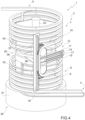
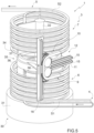
- Figures 1 to 5 show the store 1 in successive operating phases while the store 1 is filled. These figures show the information disclosed above, namely that the rotation movement is also associated with a variation in the length of the segment IS (in other words, a variation in the distance between the pulleys 13 and 14).
- the conveyor 6 comprises at least a motorised pulley 23 and the conveyor 7 comprises at least a motorised pulley 24.
- the pulleys 23 and 24 are designed to allow a transporting element 25 and a transporting element 26, respectively, to move along the segment S1 and S2, respectively, (and along relative return segments).
- the segments S1 and the respective return segment define, together, a path closed on itself (typical of an endless conveyor).
- the segments S2 and the respective return segment define, together, a path closed on itself (typical of an endless conveyor).
- the transporting element 25 is, according to some non-limiting embodiments, a belt and/or a chain.
- the transporting element 25 is a chain. More precisely, the transporting element 25 is a chain as disclosed, for example, in US6364094 and/or WO2013141807 .
- the transporting element 26 is, according to some non-limiting embodiments, a belt and/or a chain.
- the conveyor element 26 is a chain. More precisely, the transporting element 26 is a chain as disclosed, for example, in US6364094 and/or WO2013141807 .
- the transporting elements 25 and 26 allow the articles 2 to be handled delicately.
- the conveyor 6 comprises ( figure 7 ) a guide (a track) 27.
- the transporting element 25 is configured to slide on the guide 27.
- the guide 27 is provided with an indent 28, inside which a (lower) protuberance of the transporting element 25 extends. Thanks to this structure, the element 25 follows the guide 27 and moves along the segment S1. To this regard, it should be pointed out that the guide 27 extends along the path S1; more precisely, the guide 27 has the shape of the path S1 (and defines the path S1).
- the conveyor 7 comprises a guide (track) 29.
- the transporting element 26 is configured to slide on the guide 29.
- the guide 29 has a structure and function similar to the guide 27.
- the guide 29 extends along the path S2; more precisely, the guide 29 has the shape of the path S2 (and defines the path S1).
- the first centring elements 9" are arranged on opposite sides of the guide 27 and substantially in contact with the guide 27.
- centring elements 10" are arranged on opposite sides of the guide (29) and substantially in contact with the guide 29.
- the store 1 also comprises a main support structure 30 carrying the conveyors 6 and 7 (more precisely, the guides 27 and 29) and the transfer conveyor assembly 8.
- the main support structure 30 comprises a base 31 and a support column 32 (perpendicularly) projecting from the base 31.
- the column 32 extends parallel to the axis A; more in particular, the column 32 extends along the axis A (in other words, the axis A - also - is the longitudinal axis of the column 32). More precisely, the column 31 has a vertical orientation.
- the main support structure 30 also comprises a support assembly 33 fixed on the column 32 and carrying the conveyor 6 (more precisely, the guide 27) and a support assembly 34 fixed on the column 32, spaced apart from the support assembly 33 and carrying the conveyor 7 (more precisely, the guide 29).
- the main support structure 30 also comprises a bearing 35, which, in particular, is interposed between the support assembly 33 and the support assembly 34 and is carried by the support assembly 33.
- the bearing 35 is part of the moving assembly 12. More precisely, the bearing 35 comprises a fixed portion 36 mounted on the support assembly 33 and a movable portion 37 configured to rotate around the axis A and carrying the transfer conveyor assembly 8. More in detail, the transfer conveyor assembly 8 is mounted so as to be integral to the bearing 35 (more precisely, to the movable portion 34) by means of two arms 38.
- the moving assembly 12 comprises at least a motor (of a known type and not shown) configured to move the transfer conveyor assembly 8 (more precisely, to rotate the transfer conveyor assembly 8 around the axis A).
- the store 1 comprises sensors (encoders - of a known type and not shown) to detect the difference in speed between the conveyors 6 and 7 (more precisely, between the motorised pulleys 24 and 25) and a control unit to operate the moving assembly 12 as a function of this difference.
- the aforementioned actuator assembly (for moving the pulleys 13 and 14 towards and away from one another) comprises a kinematic mechanism (for example, a gear system with a worm screw) connected to the motor of the moving assembly 12 to transmit the motion (according to a particular proportion) to the pulleys 13 and 14 (in order to have them move towards and away from one another).
- a kinematic mechanism for example, a gear system with a worm screw
- the transfer conveyor assembly 8 is configured to change the speed at which the length of the transfer segment IS changes as a function of the rotation speed generated by the moving assembly 12 around the rotation axis (to this regard, see, for example, WO2019073447A1 ).
- the moving assembly 12 comprises a mechanical connection configured to move the transfer conveyor assembly 8 (more precisely, to rotate the transfer conveyor assembly 8 around the axis A) as a function of the speed differences between the conveyors 6 and 7 (more precisely, between the motorised pulleys 24 and 25).
- the store 1 is placed between a first machine (for example, a cigarette maker machine) and the machine M (for example, a packer machine) so as to compensate for the different speeds at which the first machine feeds the articles 2 to the store 1 and the machine M uses the articles 2 coming from the store.
- the store 1 comprises a control system (of which the control unit CU is part) connected to the first and to the second machine (for receiving information on the speeds) and configured to adjust the speed of the conveyor 6 so as to adapt it to the speed of the first machine (and to adjust the speed of the conveyor 7 so as to adapt it to the speed of the machine M).
- the joining device 9' comprises a central element 42, on which, in use, the articles 2 shift from the first conveyor 6 to the transfer conveyor assembly 8.
- the centring elements 9" are arranged on opposite sides of the central element 42 (and are substantially integral to the central element 42).
- the joining device 10' comprises a central element 43, on which, in use, the articles 2 shift from the transfer conveyor assembly 8 to the second conveyor 7.
- the centring elements 10" are arranged on opposite sides of the central element 43 (and are substantially integral to the second central element 42).
- the joining device 9' comprises at least an adjustment device for adjusting the position of the centring elements 9" relative to the conveyor 6 (in particular, relative to the guide 27). In particular, in this way it is possible to adjust the position of the centring elements 9" so that they are in contact with the guide 27.
- the joining device 10' comprises at least an adjustment device for adjusting the position of the centring elements 10" relative to the conveyor 7 (in particular, relative to the guide 29). In particular, in this way it is possible to adjust the position of the centring elements 10" so that they are in contact with the guide 29.
- an adjustment device is provided for each centring element 9" and 10".
- each adjustment device comprises (is) an eccentric (which can be operated, for example, by means of a screwdriver or the like).
- the central element 42 has at least a distal portion 44 relative to the transfer conveyor assembly 8 (namely, arranged at a distal end with respect to the transfer conveyor assembly 8), which is tapered towards the conveyor 6.
- the central element 43 has at least a distal portion 45 relative to the transfer conveyor assembly 8 (namely, arranged at a distal end with respect to the transfer conveyor assembly 8), which is tapered towards the second conveyor 7.
- the central elements 42 act as chutes.
- the transporting element 25 (in particular, a belt and/or a chain) is configured to slide along at least the segment S1 and has at least a depression 46 (in particular, at least two depressions 46), which longitudinally extends along the transporting element 25.
- the transporting element 26 is configured to slide along at least the segment S2 and has at least a depression 47 (in particular, at least two depressions 47), which longitudinally extends along the transporting element 26.
- the first central element 42 has at least a tine 48 (more in particular, at least two tines), which projects on the opposite side relative to the transfer conveyor assembly 8 (in particular, from the distal portion 44) and, in particular, at least partially extends inside the depression 46.
- the central element 43 has at least two tines 49, which project on the opposite side relative to the transfer conveyor assembly 8 (in particular, from the distal portion 45) and, in particular, (each) at least partially extend inside a (respective) depression 46.
- each tine 48 and 49 is tapered towards its free end (in particular, away from the transfer conveyor assembly 8).
- the joining device 9' comprises at least a lower roller 50 (in particular, a bearing), which is arranged in contact with the conveyor 6 (in particular, in contact with the transporting element 25; in particular, is arranged between the central element 42 and the conveyor 6) and is configured to help the first joining device 9' slide on the first conveyor 6.
- the lower roller 50 has a rotation axis transverse to the segment S1.
- the joining device 9' comprises at least two lower rollers 50 that are offset relative to one another (and/or staggered, in particular as regards the position along the segment S1).
- the joining device 10' comprises at least two lower rollers 51 that are offset relative to one another (and/or staggered, in particular as regards the position along the segment S2) .
- the joining device 9' comprises at least an adjustment device for adjusting the position of the lower roller/s 50 relative to the conveyor 6 (in particular, relative to the transporting element 25).
- the joining device 10' comprises at least an adjustment device for adjusting the position of the lower roller/s 51 relative to the conveyor 7 (in particular, relative to the transporting element 26).
- each adjustment device comprises (is) an eccentric (which can be operated, for example, by means of a screwdriver or the like).
- the conveyor assembly 3 comprises a hinge 52, which is arranged between the joining device 9' and the transfer conveyor assembly 8 and is configured to allow the joining device 9' to pivot relative to the transfer conveyor assembly 8 around a respective pivoting axis (in particular, transverse to the segment S1).
- the conveyor assembly 3 comprises a hinge 53, which is arranged between the joining device 10' and the transfer conveyor assembly 8 and is configured to allow the joining device 10' to pivot relative to the transfer conveyor assembly 8 around a respective pivoting axis (in particular, transverse to the segment S1).
- the store 1 offers several advantages relative to the state of the art. Among others, it should be pointed out that, in this way, it is possible to have a relatively uncomplicated structure that permits relatively simple maintenance operations. Furthermore, the store 1 is particularly flexible, for it is able to also have an output station at the top (a particularly convenient position for the layouts of the current machines), and is delicate in handling the items 2.
- the connections of the transfer conveyor assembly 8 to the conveyors 6 and 7 are stable and reliable. The risks of clogging of articles 2 and/or that these clogs are large and/or that articles 2 are damaged are also reduced.
- a plant (of the tobacco processing industry) comprising the store 1 and the machine M described above.
- the plant also comprises a first machine (for example, a machine for the production of cigarettes); the store 1 is, in these cases, arranged between the first machine and the machine M.
- An unloading device 5' is arranged in the area of the output station 5 and comprises: at least a third conveyor 5", which transfers the articles 2 to the machine M; a compensation area CA, which is arranged downstream of the conveyor 7 and upstream of the conveyor 5" (between the conveyor 7 and the conveyor 5") and contains a variable quantity of articles 2 (so as to at least partially compensate for capacity differences between the conveyor 7 and the conveyor 5"); and a control unit CU, which adjusts the operating speed of the conveyor 5" as a function of the requests of the machine M and the operating speed of the conveyor 7 as a function of a degree of filling of the compensation area CA.
- the conveyor 7 conveys the articles 2 towards the unloading device 5' (in particular, towards the compensation area CA) in a direction D1; the conveyor 5" conveys the articles 2 coming from the compensation area CA in a direction D2 different from (in particular, at least partially contrary to) the direction D1.
- the method comprises a feeding step, during which a feeding conveyor 7' receives the articles 2 from the conveyor 7 and feeds the articles 2 to the compensation area CA (in particular, in the direction D1).
- the control unit CU adjusts the operating speed of the feeding conveyor 7' as a function of the degree of filling of the compensation area CA.
- the unloading device 5' comprises a detection system DS, which detects a level of the articles within the compensation area CA and is connected to the control unit CU.
- the control unit CU adjusts the operating speed of the feeding conveyor 7' (and, in particular, of the conveyor 7) as a function of the data detected by the detection system DS (in particular, as a function of the level of the articles within the compensation area CA).
- the detection system DS comprises at least a deformable belt 54, which changes its position within the compensation area as a consequence of the level of the articles within the compensation area CA, and a sensor 55 detects the position of the deformable belt 54.
- the method is implemented by the store 1 as described above.
Landscapes
- Engineering & Computer Science (AREA)
- Mechanical Engineering (AREA)
- Intermediate Stations On Conveyors (AREA)
Abstract
an unloading device (5') comprises: a third conveyor (5") for transferring the articles (2) to a machine (M) arranged downstream of the store (1), a compensation area (CA) for containing a variable quantity of articles (2), and a control unit (CU) for adjusting the speed of the third conveyor (5") and of the second conveyor (7).

Description
- This patent application claims priority from
Italian patent application no. 102023000018318 filed on September 6, 2023 - The invention relates to a variable-capacity store, to a method of conveying articles, in particular cylindrical articles of the tobacco processing industry, and to a plant.
- Variable-capacity stores for cigarettes of the type described in patent
EP581143 -
EP838165 - This type of stores is affected by several drawbacks, among which the following ones are worth being mentioned.
- The particular arrangement of the two conveying portions arranged one within the other not only makes the structure and construction of the stores particularly complex and expensive, but also significantly complicates maintenance operations.
- In addition, the stores are not very ductile as it is not possible to provide input and output stations for the cylindrical articles arranged in desired positions (for example, one at the bottom and one at the top). More in particular, according to
EP581143 EP838165 - Furthermore, please note that pneumatic conveyors (like, for example, the ones disclosed in
EP838165 - In addition, conveying relatively delicate items (such as cigarettes) exclusively by gravity can lead to damage to the articles and/or to the creation of clogs.
-
WO2019073447A1 discloses a variable-capacity store for articles of the tobacco processing industry, comprising a conveyor assembly comprising a first conveyor having a substantially helical shape; a second conveyor with a substantially helical shape and arranged above the first conveyor; a linear transfer conveyor, designed to convey the articles from the first conveyor to the second conveyor, having a variable length. This type of stores suffers from some defects, among which the following ones are worth being mentioned: the fact that it is difficult to be able to precisely adjust the flow of articles leaving the store (and, hence, supplied to following machines); the system is rather rigid with regard to the direction of the articles leaving the store (and, therefore, does not give the possibility of correctly exploiting the spaces available for the positioning of following machines). - The object of the invention is to provide a variable-capacity store, a method of conveying articles, in particular cylindrical articles of the tobacco processing industry, and a plant, which are designed to at least partially overcome the drawbacks of the prior art and, at the same time, are easy and economic to be manufactured and implemented.
- In accordance with the invention, there are provided a variable-capacity store, a method of conveying articles (in particular, cylindrical articles of the tobacco processing industry) and a plant as claimed in the accompanying independent claims and, preferably, in any one of the claims that directly or indirectly depend on the aforesaid independent claims.
- The invention will now be described with reference to the accompanying drawings showing a non-limiting embodiment thereof, wherein:
-
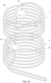
figures 1 to 5 are perspective views, with parts removed for greater clarity, of successive operating configurations of a part of the store in accordance with the invention; -
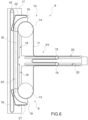
figure 6 is a side view of a component of the store offigures 1-5 ; -
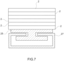
figure 7 is a cross section of a detail of the store offigures 1-5 ; -
figure 8 is a perspective view of the machine offigures 1-5 with some details left out for greater clarity; -
figure 9 is a perspective view of the component offigure 6 connected to a further element; -
figure 10 is a perspective view of components of the store offigures 1-5 ; -
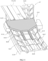
figure 11 is a perspective view of a detail of the store offigures 1-5 ; -
figure 12 is a perspective view from the bottom of a detail offigure 11 ; -
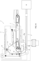
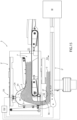
figure 13 is a perspective view of the store offigures 1-5 ; and -
figures 14 and15 show a detail, on a larger scale, of the store offigure 13 in two different operating configurations. - In the accompanying figures,
number 1 indicates, as a whole, a variable-capacity store forarticles 2. The store comprises aconveyor assembly 3 for conveying the articles 2 (in particular, in a mass) from aninput station 4 to anoutput station 5 along a path P (in particular, with a variable length). - In particular, the
articles 2 are substantially cylindrical articles, more in particular of the tobacco processing industry. For example, thearticles 2 are cigarettes, cigarette filters, cigarette filter components (rods), tobacco rods, cartridges and/or components for electronic cigarettes. According to some specific and non-limiting embodiments, thearticles 2 are cigarettes. - The
conveyor assembly 3 comprises aconveyor 6 for conveying thearticles 2 from theinput station 4 along a segment S1 of the path P; and at least atransfer conveyor assembly 8, which is configured to convey thearticles 2 from theconveyor 6 along a transfer segment IS (in particular, with substantially linear portions) of the path P and has aninput 9, arranged in the area of thesegment S 1 to receive thearticles 2 from theconveyor 6. - In particular, the
articles 2 have an oblong shape. More in particular, theconveyor assembly 3 is designed to convey thearticles 2 in a mass (namely, in contact with one another and in several layers - see for example the enlargement of the upper part offigure 1 andfigure 15 ) and, more in particular, crosswise (namely, in a transverse direction, in particular perpendicular to their longitudinal extension). - Advantageously, though not necessarily, the
conveyor assembly 3 also comprises aconveyor 7 for conveying thearticles 2 to theoutput station 5 along a segment S2 of the path P. In these cases, thetransfer conveyor assembly 8 is configured to convey thearticles 2 from theconveyor 6 to theconveyor 7 along the transfer segment IS (in particular, the substantially linear transfer segment) of the path P and has aninput 10, arranged in the area of the segment S2 to feed the articles to theconveyor 7. - In particular, the
conveyors 6 and 7 (and, in some cases, also the transfer conveyor assembly 8) are endless conveyors. - According to some non-limiting embodiments, the
transfer conveyor assembly 8 is arranged between theconveyors - Advantageously, though not necessarily, the
transfer conveyor assembly 8 is arranged on the side of theconveyors - Advantageously, though not necessarily, the
transfer conveyor assembly 8 is configured to convey thearticles 2 upwards. - The segment S1 (which, in particular, has a substantially helical shape) extends from the
input station 4 to theinput 9. The segment S2 (which, in particular, has a substantially helical shape) extends from theoutput 10 to theoutput station 5. - According to some non-limiting embodiments, the
store 1 further comprises a movingassembly 12 for moving thetransfer conveyor assembly 8 so as to move saidinput 9 and saidoutput 10 along theconveyor 6 and theconveyor 7, respectively. In particular, themoving assembly 12 also is (consequently) configured to change the length of the transfer segment IS and of thesegments S 1 and S2. - It should be noted that, by lengthening the segments S1 and S2, the length of the path P (and, hence, the capacity of the store 1) increases; by shortening the segments S1 and S2, the length of the path P (and, hence, the capacity of the store 1) decreases.
- With particular reference to
figures 13 ,14 and15 , thestore 1 also comprises an unloading device 5', which is arranged in the area of theoutput station 5 and comprises: at least aconveyor 5", which is configured to transfer thearticles 2 to a machine M arranged downstream of thestore 1; a compensation area CA, which is arranged downstream of theconveyor 7 and upstream of theconveyor 5" (in particular, between theconveyor 7 and theconveyor 5") and is configured to contain a variable quantity of articles 2 (so as to at least partially compensate for capacity differences between theconveyor 7 and theconveyor 5"); and a control unit CU, which is configured to adjust the operating speed of theconveyor 5" as a function of the requests of the machine M and, in particular, the operating speed of theconveyor 7 as a function of the degree of filling of the compensation area CA (namely, how filled it is, in particular relative to its total capacity). - Tests have shown that in this way it is possible to fine-tune the flow of
articles 2 to the machine M by precisely supplying the quantity of articles it needs. - In this context, it should be pointed out that the
conveyor assembly 3 itself can be used to compensate for the different operating speeds (and/or momentary standstills) of a machine (for example, a machine for the production of articles 2 - of a known type and not shown) designed to feed thearticles 2 to theinput station 4 and of the machine M (for example, configured to combine thearticles 2 with other components to produce a final product or to pack the articles 2). - Therefore, it is surprising that tests have shown that the presence of the unloading device 5' significantly improves the supply to the machine M (and, hence, the operation of the machine M itself).
- In particular, the compensation area CA comprises (more in particular, is) a variable-volume compensation chamber.
- In particular, in use, the control unit CU decreases the quantity (per time unit) of
articles 2 fed to the unloading device 5' (by decreasing the speed of the conveyor 7) when the compensation area CA fills (beyond a certain limit). In addition or alternatively, vice versa, the control unit CU increases the quantity (per time unit) ofarticles 2 fed to the unloading device 5' (by increasing the speed of the conveyor 7) when the compensation area CA empties (beyond a certain limit). - In particular, in use, the control unit CU decreases the speed of the
conveyor 5" when the machine M needsfewer articles 2 and increases the speed of theconveyor 5" when the machine M needsmore articles 2. - Advantageously, though not necessarily, the
conveyor 7 is configured to convey thearticles 2 towards the unloading device 5' (in particular, towards the compensation area CA; more in particular, to the compensation area CA) in a direction D1; theconveyor 5" is configured to convey thearticles 2 coming from the compensation area CA in a second direction D2 different from the direction D1 (in particular, at least partially contrary to the first direction D1). - In this way, it is possible to place the machine M in a more suitable position and, therefore, reduce the overall dimensions.
- The unloading device 5' comprises a feeding conveyor 7', which is configured to receive the
articles 2 from theconveyor 7 and to feed thearticles 2 to the compensation area CA (in particular, in the direction D1); the control unit CU is configured to adjust the operating speed of the feeding conveyor 7' (and, in particular, of the conveyor 7) as a function of the degree of filling of the compensation area CA. - In particular, in use, the control unit CU decreases the speed of the feeding conveyor 7' when the compensation area CA fills (beyond a certain limit). In addition or alternatively, vice versa, the control unit CU increases the speed of the feeding conveyor 7' when the compensation area CA empties (beyond a certain limit).
- Advantageously, though not necessarily, the unloading device 5' is configured to feed the
articles 2 to the machine M in a mass with a controlled height (in particular, ranging from a maximum height to a minimum height). - According to some non-limiting embodiments, the unloading device 5' comprises a detection system DS, which is configured to detect a level of the
articles 2 within the compensation area CA and is connected to said control unit CU. The control unit CU is configured to adjust the operating speed of the feeding conveyor 7' (and, in particular, of the conveyor 7) as a function of the data detected by the detection system DS (in particular, as a function of the level of the articles within the compensation area CA). In particular, the detection system DS comprises at least adeformable element 54, which is configured to change its position within the compensation area CA as a consequence of the level of the articles within the compensation area CA, and asensor 55 configured to detect the position of the deformable element 54 (e.g. thesensor 55 is a proximity sensor). - This structure is particularly simple and functional.
- For example, the
deformable element 54 is a deformable band or a deformable wall (comprising a plurality of panels hinged to one another). - Advantageously, though not necessarily, the unloading device 5' comprises a
transfer channel 56 for taking thearticles 2 from the compensation area CA to theconveyor 5", which is arranged under the compensation area CA. - In this way, the
articles 2 are brought onto theconveyor 5" in a simple (inexpensive) and efficient manner. - In particular, the
transfer channel 56 is substantially vertical. - Advantageously, though not necessarily, the unloading device 5' has a levelling
wall 58, which is arranged above theconveyor 5" and is configured to limit a height of a mass ofarticles 2 arranged on theconveyor 5", and anoutput channel 57, which is connected to thetransfer channel 56 and is delimited, at the bottom, by theconveyor 5" and, at the top, by the levellingwall 58. - Tests have shown that this structure makes it possible to obtain a particularly constant supply to the machine M in a simple and inexpensive manner.
- According to some non-limiting embodiments (e.g. as shown in
figures 11 and12 ), theconveyor assembly 3 comprises a joining device 9', which is configured to allow thearticles 2 to shift from theconveyor 6 to thetransfer conveyor assembly 8 and is movable on theconveyor 6. In some cases, theconveyor assembly 3 also comprises a joining device 10', which is configured to allow thearticles 2 to shift from thetransfer conveyor assembly 8 to theconveyor 7 and is movable on theconveyor 7. - In particular, the joining device 9' comprises at least two
centring elements 9", which are arranged on opposite sides of theconveyor 6 to reduce the lateral movement of the joining device 9' relative to theconveyor 6. - In particular, the joining device 10' comprises at least two centring
elements 10", which are arranged on opposite sides of theconveyor 7 to reduce the lateral movement of the joining device 10' relative to theconveyor 7. - Each
centring element 9" comprises at least a first roller (in particular, at least a roller bearing) and/or eachcentring element 10" comprises at least a second roller (in particular, at least a roller bearing). - Tests have shown that, in this way, it is possible to obtain more stable and reliable connections of the
transfer conveyor assembly 8 to theconveyors 6 and/or 7 (a more precise relative position) and a reduction in clogging events. - Advantageously, though not necessarily, the conveying
assembly 3 comprises both the joining device 9' and the joining device 10'. - According to some preferred, though non-limiting embodiments, the joining devices 9' and 10' are substantially identical. To this regard, it should be pointed out that
figures 11 and12 show both the joining device 9' and the joining device 10'. - In particular, the moving assembly 12 (
figures 1-5 ) is configured to move thetransfer conveyor assembly 8 so as to move the joining device 9' and/or the joining device 10' along theconveyors - Advantageously, though not necessarily, the
transfer conveyor assembly 8 has at least an advancingdevice 11 configured to (at least partially) accompany thearticles 2, moving (together with the articles) along an intermediate portion of the transfer segment IS. In particular, said intermediate portion of the transfer segment IS extends upwards, more in particular is substantially vertical. - According to some non-limiting embodiments, the advancing
device 11 comprises (is) an oblong element closed on itself. In particular, the advancingdevice 11 comprises (is) a belt and/or a chain. - Thanks to the presence of the advancing
device 11, the risks of clogging ofarticles 2 along the transfer segment IS and of damaging thearticles 2 while, in use, they are conveyed along the transfer segment IS are reduced. Thanks to the advancingdevice 11, it is also possible to feed thearticles 2 from theconveyor 6 arranged at the bottom to theconveyor 7 arranged at the top. - Advantageously, though not necessarily, the advancing
device 11 is configured to (at least partially) move thearticles 2, moving (together with the articles) along the transfer segment IS. - In particular, the transfer segment IS extends between the
input 9 and the output 10 (more in particular, from theinput 9 to the output 10). - The
input 9 and theoutput 10 are movable along theconveyor 6 and theconveyor 7, respectively. - In particular, each
conveyor conveyor conveyor conveyor 6 is contrary to the winding direction of theconveyor 7. For example, if (looking from above) the winding direction of theconveyor 7 is clockwise, the winding direction (always looking from above) of theconveyor 6 is counterclockwise. - Advantageously, though not necessarily, the
conveyor 6 has a plurality of first turn (loops) and thesecond conveyor 7 has a plurality of second turns (loops) having the same radius and the same distance as the first turns. - According to specific non-limiting embodiments, the
conveyor 6 has a plurality of turns with a constant radius and distance; theconveyor 7 has a plurality of turns with a constant radius and distance. More precisely, theconveyor 6 has at least a segment with a (cylindrical) helical shape with a constant radius and distance; theconveyor 7 has at least a segment with a (cylindrical) helical shape with a constant radius and distance. - According to alternative embodiments which are not shown herein, each turn comprises two curved end portions and two linear central portions. In these cases, for example, the turns extend around two drums having parallel axes (see, for example,
figure 1 ofEP738478 - Advantageously, though not necessarily, the
transfer conveyor assembly 8 comprises a pulley 13 (or, alternatively, a suitably shaped - for example, "U"-shaped - sliding plane) and apulley 14, around which the advancingdevice 11 is partially wound. - In particular, the store 1 (more precisely, the transfer conveyor assembly 8) comprises at least an operating assembly (of a known type and not shown) for rotating at least one of the
pulleys transfer conveyor assembly 8 is structured in such a way that theoutput 10 is arranged approximately in the area (more precisely, at the height) of thepulley 14 and theinput 9 is arranged in the area (more precisely, at the height) of the pulley 13 (or of the sliding plane alternative to the pulley 13). - According to some non-limiting embodiments, the aforementioned operating assembly comprises (is) a motor and/or a kinematic mechanism connected to other parts of the
store 1. - Advantageously, though not necessarily, the store 1 (in particular, the
transfer conveyor assembly 8; more in particular, the moving assembly 12) comprises an actuator assembly (of a known type and not shown) for moving thepulleys - According to some non-limiting embodiments, the aforementioned actuator assembly comprises (is) a motor and/or kinematic mechanism connected to other parts of the
store 1. - In particular, the aforementioned actuator assembly is configured to change the distance between the
pulleys conveyor 6 and theconveyor 7 convey thearticles 2. More in particular, the actuator assembly is configured to change the distance between thepulleys conveyor 6 and theconveyor 7 convey thearticles 2. - According to some non-limiting embodiments, the advancing
device 11 comprises an active segment AT with a variable length, which extends along (the intermediate portion of) the transfer segment IS between thepulleys pulleys pulleys pulleys further pulley 15 of thetransfer conveyor assembly 8, which also includes a further actuator assembly (also known and not shown) for moving the pulley 15 (away from and towards the transfer segment IS). - Advantageously, the relative movement between the
pulleys pulley 15 are connected to one another so that one compensates for the other (and the advancingdevice 11 always remains correctly stretched). In other words, when the active segment AT gets shorter by a given length, the passive segment PT gets longer by the given length and vice versa (compensating for one another). - In some non-limiting cases, the further actuator assembly comprises a kinematic mechanism, which transfers, according to a defined proportional ratio (for example 1 to 1), the relative movement (more precisely, the displacement) of the
pulleys pulley 15. - In particular, the
transfer conveyor assembly 8 comprises at least apulley 15 and at least two fixed pulleys (known and not shown - typically, arranged one above the other). More precisely, though not necessarily, thepulley 15 is arranged (at an intermediate height) between the two fixed pulleys and is (horizontally) movable towards and away from the fixed pulleys. The relative movement between thepulley 15 on the one hand and the fixed pulleys on the other hand compensates for the relative movement between thepulleys 13 and 14 (by lengthening the passive segment PT when the active segment AT is shortened and vice versa). - According to some specific and non-limiting embodiments (like the one shown herein), the
transfer conveyor assembly 8 comprises at least twopulleys 15 and at least three fixed pulleys (known and not shown). In these cases, the relative movement between thepulleys 15 on the one hand and the fixed pulleys on the other hand compensates for the relative movement between thepulleys 13 and 14 (by lengthening the passive segment PT when the active segment AT shortens and vice versa). - Advantageously, though not necessarily, the
transfer conveyor assembly 8 comprises at least a further advancingdevice 16, which faces the advancingdevice 11 and is configured to move along the intermediate portion of the transfer segment IS (in particular, in coordination with the advancingdevice 11; more precisely, at the same speed as the advancing device 11). In particular, the advancingdevice 11 and the advancingdevice 16 are designed to clamp thearticles 2 between them and to at least partially accompany them (move them) along the transfer segment IS. - More precisely, the advancing
device 16 comprises (is) a belt and/or a chain. - Advantageously, though not necessarily, the
transfer conveyor assembly 8 comprises a motor (electric motor - of a known type and not shown) to operate (rotate) one of the pulleys 16' and a different motor (electric motor - of a known type and not shown) to operate (rotate) one of thepulleys 14 and 13 (in particular, the pulley 14). In particular, the store 1 (more precisely, the transfer conveyor assembly 8) comprises a control unit configured to operate the two electric motors in a coordinated manner so that the speeds of the advancingdevices pulleys pulleys articles 1 along the segment IS), the rotation speed of thepulley 14 is decreased. - According to some alternative and non-limiting embodiments, the advancing
device 16 is wound around a pair of pulleys 16' (one of them being shown infigures 1-6 and the other one being shown infigure 13 ). In particular, one of the pulleys 16' is connected, by means of a kinematic mechanism (known and not shown), to at least one of thepulleys pulleys devices - Thanks to the advancing
device 16, the risks of clogging ofarticles 2 along the transfer segment IS and of damaging thearticles 2 while, in use, they are conveyed along the transfer segment IS are further reduced. Thanks to the advancingdevice 16, it is also possible improve the feeding of thearticles 2 from theconveyor 6 arranged at the bottom to theconveyor 7 arranged at the top. - According to some non-limiting embodiments, the
transfer conveyor assembly 8 comprises aplate 17, on which the aforementioned pulleys (in particular, thepulleys pulley 15, the pulleys 16' and the fixed pulleys) are mounted. In particular, theplate 17 hasslits 18, which act as a guide for thepulleys pulleys respective slit 18. - Alternatively or in addition, the
transfer conveyor assembly 8 comprises twoflat supports 19, on which thepulleys - In some cases, the
flat supports 19 can slide along theslits 18 or are movable along linear guides. The movement of theflat supports 19 can be obtained, for example, by means of linear actuators and/or kinematic mechanisms connected to other parts of thestore 1. - In addition or alternatively, the
plate 17 hasslits 20, which act as a guide for the pulley/s 15. In other words, in use, the pulley/s 15 slide/s along arespective slit 20. - According to alternative non-limiting embodiments, the
pulleys 15 are mounted on respective sliders movable along linear guides. The movement of these sliders can be obtained, for example, by means of linear actuators and/or kinematic mechanisms connected to other parts of thestore 1. - Advantageously, though not necessarily, the joining device 9' and the joining device 10' move in the direction of the longitudinal extension of the transfer segment IS in an integral manner to a
respective pulley - According to some non-limiting embodiments, the
transfer conveyor assembly 8 further comprises adeflector belt 21 arranged in the area of thepulley 13 for directing (modifying their advancing direction) thearticles 2, coming from theinput 9, in the transfer segment IS. In addition or alternatively, thetransfer conveyor assembly 8 further comprises adeflector belt 22 arranged in the area of thepulley 14 for directing (modifying their advancing direction) thearticles 2, coming from the transfer segment IS, towards theoutput 10. - In particular, the
deflector belts pulleys deflector belts flat support 19. - Advantageously, though not necessarily, the
conveyors conveyor 7 is (at least partially) arranged above the conveyor 6 (and theoutput station 5 is arranged higher than the input station 4). By so doing, it is possible to have theoutput 10 in a relatively high position relative to theinput 9. - In some non-limiting cases, the
output station 5 is arranged higher (than the input 9) and than theinput station 4. In particular, theoutput station 5 is arranged higher than theoutput 10, which, in turn, is arranged higher than theinput 9, which is arranged higher than theinput station 4. - More precisely (the
conveyors - According to some non-limiting embodiments, the aforementioned intermediate portion of the transfer segment IS is (linear and) substantially parallel to an axis A around which the segment S1 and the segment S2 are wound.
- In accordance with specific non-limiting embodiments, the segment IS also has two connection portions SC1 and SC2 (which are transverse - in particular, perpendicular - to the intermediate portion), which extend between the intermediate portion of the transfer segment IS and the segments S1 and S2, respectively. The
transfer conveyor assembly 8 is configured to also convey thearticles 2 along the connection portions SC1 and SC2. - More precisely, though not necessarily, the connecting portions SC1 and SC2 extend substantially horizontally.
- According to some non-limiting embodiments, the
transfer conveyor assembly 8 comprises conveyors with (substantially horizontal) movable transporting elements in the area of the connection portions SC1 and SC2. - Advantageously, though not necessarily, the moving
assembly 12 is configured to rotate thetransfer conveyor assembly 8 around the axis A. - In use, while the moving
assembly 12 rotates thetransfer conveyor assembly 8 around the axis A, the input 9 (more precisely, the joining device 9') moves (slides) along theconveyor 6 and the output 10 (more precisely, the joining device 10') moves (slides) along theconveyor 7. In order to have theinput 9 follow theconveyor 6 and theoutput 10 follow theconveyor 7, the distance between thepulleys -
Figures 1 to 5 show thestore 1 in successive operating phases while thestore 1 is filled. These figures show the information disclosed above, namely that the rotation movement is also associated with a variation in the length of the segment IS (in other words, a variation in the distance between thepulleys 13 and 14). - As better shown in
figure 10 , theconveyor 6 comprises at least amotorised pulley 23 and theconveyor 7 comprises at least amotorised pulley 24. Thepulleys element 25 and a transportingelement 26, respectively, to move along the segment S1 and S2, respectively, (and along relative return segments). The segments S1 and the respective return segment define, together, a path closed on itself (typical of an endless conveyor). The segments S2 and the respective return segment define, together, a path closed on itself (typical of an endless conveyor). - The transporting
element 25 is, according to some non-limiting embodiments, a belt and/or a chain. Advantageously, though not necessarily, the transportingelement 25 is a chain. More precisely, the transportingelement 25 is a chain as disclosed, for example, inUS6364094 and/orWO2013141807 . - The transporting
element 26 is, according to some non-limiting embodiments, a belt and/or a chain. Advantageously, though not necessarily, theconveyor element 26 is a chain. More precisely, the transportingelement 26 is a chain as disclosed, for example, inUS6364094 and/orWO2013141807 . - The transporting
elements articles 2 to be handled delicately. - Advantageously, though not necessarily, the
conveyor 6 comprises (figure 7 ) a guide (a track) 27. - In particular, the transporting
element 25 is configured to slide on theguide 27. - According to some non-limiting embodiments, the
guide 27 is provided with an indent 28, inside which a (lower) protuberance of the transportingelement 25 extends. Thanks to this structure, theelement 25 follows theguide 27 and moves along the segment S1. To this regard, it should be pointed out that theguide 27 extends along the path S1; more precisely, theguide 27 has the shape of the path S1 (and defines the path S1). - In addition or alternatively, the
conveyor 7 comprises a guide (track) 29. - In particular, the transporting
element 26 is configured to slide on theguide 29. - According to some non-limiting embodiments, the
guide 29 has a structure and function similar to theguide 27. Theguide 29 extends along the path S2; more precisely, theguide 29 has the shape of the path S2 (and defines the path S1). - Advantageously, though not necessarily, the
first centring elements 9" are arranged on opposite sides of theguide 27 and substantially in contact with theguide 27. - In addition or alternatively, the
centring elements 10" are arranged on opposite sides of the guide (29) and substantially in contact with theguide 29. - With particular reference to
figure 8 , according to some non-limiting embodiments, thestore 1 also comprises amain support structure 30 carrying theconveyors 6 and 7 (more precisely, theguides 27 and 29) and thetransfer conveyor assembly 8. - According to some non-limiting embodiments, the
main support structure 30 comprises abase 31 and a support column 32 (perpendicularly) projecting from thebase 31. In particular, thecolumn 32 extends parallel to the axis A; more in particular, thecolumn 32 extends along the axis A (in other words, the axis A - also - is the longitudinal axis of the column 32). More precisely, thecolumn 31 has a vertical orientation. - According to some non-limiting embodiments, the
main support structure 30 also comprises asupport assembly 33 fixed on thecolumn 32 and carrying the conveyor 6 (more precisely, the guide 27) and asupport assembly 34 fixed on thecolumn 32, spaced apart from thesupport assembly 33 and carrying the conveyor 7 (more precisely, the guide 29). - Furthermore, in some cases (like the one shown herein), the
main support structure 30 also comprises abearing 35, which, in particular, is interposed between thesupport assembly 33 and thesupport assembly 34 and is carried by thesupport assembly 33. Thebearing 35 is part of the movingassembly 12. More precisely, thebearing 35 comprises a fixedportion 36 mounted on thesupport assembly 33 and amovable portion 37 configured to rotate around the axis A and carrying thetransfer conveyor assembly 8. More in detail, thetransfer conveyor assembly 8 is mounted so as to be integral to the bearing 35 (more precisely, to the movable portion 34) by means of twoarms 38. - According to some non-limiting embodiments, the moving
assembly 12 comprises at least a motor (of a known type and not shown) configured to move the transfer conveyor assembly 8 (more precisely, to rotate thetransfer conveyor assembly 8 around the axis A). In these cases, in particular, thestore 1 comprises sensors (encoders - of a known type and not shown) to detect the difference in speed between theconveyors 6 and 7 (more precisely, between the motorised pulleys 24 and 25) and a control unit to operate the movingassembly 12 as a function of this difference. - Advantageously, though not necessarily, the aforementioned actuator assembly (for moving the
pulleys assembly 12 to transmit the motion (according to a particular proportion) to thepulleys 13 and 14 (in order to have them move towards and away from one another). - Advantageously, though not necessarily, the
transfer conveyor assembly 8 is configured to change the speed at which the length of the transfer segment IS changes as a function of the rotation speed generated by the movingassembly 12 around the rotation axis (to this regard, see, for example,WO2019073447A1 ). - According to some embodiments, the moving
assembly 12 comprises a mechanical connection configured to move the transfer conveyor assembly 8 (more precisely, to rotate thetransfer conveyor assembly 8 around the axis A) as a function of the speed differences between theconveyors 6 and 7 (more precisely, between the motorised pulleys 24 and 25). - Typically, in use, the
store 1 is placed between a first machine (for example, a cigarette maker machine) and the machine M (for example, a packer machine) so as to compensate for the different speeds at which the first machine feeds thearticles 2 to thestore 1 and the machine M uses thearticles 2 coming from the store. More precisely, thestore 1 comprises a control system (of which the control unit CU is part) connected to the first and to the second machine (for receiving information on the speeds) and configured to adjust the speed of theconveyor 6 so as to adapt it to the speed of the first machine (and to adjust the speed of theconveyor 7 so as to adapt it to the speed of the machine M). - With particular reference to
figures 11 and12 and according to some non-limiting embodiments, the joining device 9' comprises a central element 42, on which, in use, thearticles 2 shift from thefirst conveyor 6 to thetransfer conveyor assembly 8. Thecentring elements 9" are arranged on opposite sides of the central element 42 (and are substantially integral to the central element 42). - In addition or alternatively, the joining device 10' comprises a central element 43, on which, in use, the
articles 2 shift from thetransfer conveyor assembly 8 to thesecond conveyor 7. Thecentring elements 10" are arranged on opposite sides of the central element 43 (and are substantially integral to the second central element 42). - In this way, tests have shown that the relative position of the transfer conveyor assembly 8 (in particular, of the joining devices 9' and 10') with respect to the
conveyors - Advantageously, though not necessarily, the joining device 9' comprises at least an adjustment device for adjusting the position of the
centring elements 9" relative to the conveyor 6 (in particular, relative to the guide 27). In particular, in this way it is possible to adjust the position of thecentring elements 9" so that they are in contact with theguide 27. - In addition or alternatively, the joining device 10' comprises at least an adjustment device for adjusting the position of the
centring elements 10" relative to the conveyor 7 (in particular, relative to the guide 29). In particular, in this way it is possible to adjust the position of thecentring elements 10" so that they are in contact with theguide 29. - According to non-limiting embodiments, an adjustment device is provided for each
centring element 9" and 10". - In some non-limiting cases, each adjustment device comprises (is) an eccentric (which can be operated, for example, by means of a screwdriver or the like).
- Advantageously, though not necessarily, the central element 42 has at least a distal portion 44 relative to the transfer conveyor assembly 8 (namely, arranged at a distal end with respect to the transfer conveyor assembly 8), which is tapered towards the
conveyor 6. - Optionally, in addition or alternatively, the central element 43 has at least a distal portion 45 relative to the transfer conveyor assembly 8 (namely, arranged at a distal end with respect to the transfer conveyor assembly 8), which is tapered towards the
second conveyor 7. - In this way, it is easier for the
articles 2 to be transferred from and to thetransfer conveyor assembly 8, thus reducing at the same time the risk of clogging. - According to some non-limiting embodiments, the central elements 42 act as chutes.
- Advantageously, though not necessarily, the transporting element 25 (in particular, a belt and/or a chain) is configured to slide along at least the segment S1 and has at least a depression 46 (in particular, at least two depressions 46), which longitudinally extends along the transporting
element 25. - In addition or alternatively, the transporting
element 26 is configured to slide along at least the segment S2 and has at least a depression 47 (in particular, at least two depressions 47), which longitudinally extends along the transportingelement 26. - In particular, the first central element 42 has at least a tine 48 (more in particular, at least two tines), which projects on the opposite side relative to the transfer conveyor assembly 8 (in particular, from the distal portion 44) and, in particular, at least partially extends inside the depression 46.
- In addition or alternatively, the central element 43 has at least two tines 49, which project on the opposite side relative to the transfer conveyor assembly 8 (in particular, from the distal portion 45) and, in particular, (each) at least partially extend inside a (respective) depression 46.
- In this way, it is easier for the
articles 2 to be transferred from and to thetransfer conveyor assembly 8 and the risk of clogging is reduced. - Advantageously, though not necessarily, each tine 48 and 49 is tapered towards its free end (in particular, away from the transfer conveyor assembly 8).
- Advantageously, though not necessarily, the joining device 9' comprises at least a lower roller 50 (in particular, a bearing), which is arranged in contact with the conveyor 6 (in particular, in contact with the transporting
element 25; in particular, is arranged between the central element 42 and the conveyor 6) and is configured to help the first joining device 9' slide on thefirst conveyor 6. In particular, the lower roller 50 has a rotation axis transverse to the segment S1. - Tests have shown that, in this way, the sliding of the joining devices 9' and 10' is better and the risk of clogging is reduced.
- In addition or alternatively, the joining device 10' comprises at least a lower roller 51 (in particular, a bearing), which is arranged in contact with the conveyor 7 (in particular, in contact with the transporting
element 26; in particular, is arranged between the central element 43 and the conveyor 7) and is configured to help the second joining device 10' slide on thesecond conveyor 7. In particular, the lower roller 51 has a rotation axis transverse to the segment S2. - According to some non-limiting embodiments, the joining device 9' comprises at least two lower rollers 50 that are offset relative to one another (and/or staggered, in particular as regards the position along the segment S1). In addition or alternatively, the joining device 10' comprises at least two lower rollers 51 that are offset relative to one another (and/or staggered, in particular as regards the position along the segment S2) .
- Tests have shown that, in this way, the sliding of the joining devices 9' and 10' surprisingly is smoother (with smaller jolts) and the risk of clogging is reduced. This behaviour was particularly evident when the transporting
elements - It is supposed that this result is due to the fact that, with this structure, the lower rollers 50 (and/or 51) are not simultaneously located in recesses (discontinuities) of the transporting element 25 (and/or 26).
- Advantageously, though not necessarily, the joining device 9' comprises at least an adjustment device for adjusting the position of the lower roller/s 50 relative to the conveyor 6 (in particular, relative to the transporting element 25). In addition or alternatively, the joining device 10' comprises at least an adjustment device for adjusting the position of the lower roller/s 51 relative to the conveyor 7 (in particular, relative to the transporting element 26).
- In particular, in this way, it is possible to adjust the position of the lower roller/s 50 so that it/they is/are correctly in contact with the transporting
element 25 and/or the position of the lower roller/s 51 so that it/they is/are correctly in contact with the transportingelement 26. - According to non-limiting embodiments, an adjustment device is provided for each lower roller 50 and 51.
- In some non-limiting cases, each adjustment device comprises (is) an eccentric (which can be operated, for example, by means of a screwdriver or the like).
- Advantageously, though not necessarily, the
conveyor assembly 3 comprises a hinge 52, which is arranged between the joining device 9' and thetransfer conveyor assembly 8 and is configured to allow the joining device 9' to pivot relative to thetransfer conveyor assembly 8 around a respective pivoting axis (in particular, transverse to the segment S1). - In addition or alternatively, the
conveyor assembly 3 comprises a hinge 53, which is arranged between the joining device 10' and thetransfer conveyor assembly 8 and is configured to allow the joining device 10' to pivot relative to thetransfer conveyor assembly 8 around a respective pivoting axis (in particular, transverse to the segment S1). - In this case, too, a more fluid movement of the
articles 2 and a reduction in the risk of clogging were surprisingly observed. - The
store 1 according to the invention offers several advantages relative to the state of the art. Among others, it should be pointed out that, in this way, it is possible to have a relatively uncomplicated structure that permits relatively simple maintenance operations. Furthermore, thestore 1 is particularly flexible, for it is able to also have an output station at the top (a particularly convenient position for the layouts of the current machines), and is delicate in handling theitems 2. The connections of thetransfer conveyor assembly 8 to theconveyors articles 2 and/or that these clogs are large and/or thatarticles 2 are damaged are also reduced. - Unless explicitly indicated otherwise, the content of the references (articles, texts, patent applications, etc.) mentioned above is entirely quoted herein for the sake of a complete disclosure. In particular, the above-mentioned references are included herein by reference.
- According to a further aspect of the invention, there is also provided a plant (of the tobacco processing industry) comprising the
store 1 and the machine M described above. Advantageously, though not necessarily, the plant also comprises a first machine (for example, a machine for the production of cigarettes); thestore 1 is, in these cases, arranged between the first machine and the machine M. - According to a further aspect of the invention, there is provided a method of conveying
articles 2, in particular substantially cylindrical articles (more in particular, of the tobacco processing industry), from aninput station 4 to a machine M, along a path P with a variable length through anoutput station 5;
the method comprises: - a first conveying step, during which at least a
conveyor 6 conveys thearticles 2 from theinput station 4 along a segment S1 of the path P; - a second conveying step, during which a
conveyor 7 conveys thearticles 2 to theoutput station 5 along a segment S2 of the path P arranged downstream of the segment S1; - a transfer step, during which a
transfer conveyor assembly 8 conveys thearticles 2 from theconveyor 6 to theconveyor 7 along a transfer segment IS of the path P and has anoutput 10, arranged in the area of the second segment S2 for feeding (and which feeds) thearticles 2 to the second conveyor (7), and aninput 9, arranged in the area of the segment S1 for receiving (and which receives) thearticles 2 from theconveyor 6; - the method further comprises a moving step, which is at least partially simultaneous with the transfer step (and, in particular, at least partially simultaneous with the first conveying step) and during which a moving
assembly 12 shifts thetransfer conveyor assembly 8 so as to move theinput 9 and theoutput 10 along theconveyor 6 and theconveyor 7, respectively. - An unloading device 5' is arranged in the area of the
output station 5 and comprises: at least athird conveyor 5", which transfers thearticles 2 to the machine M; a compensation area CA, which is arranged downstream of theconveyor 7 and upstream of theconveyor 5" (between theconveyor 7 and theconveyor 5") and contains a variable quantity of articles 2 (so as to at least partially compensate for capacity differences between theconveyor 7 and theconveyor 5"); and a control unit CU, which adjusts the operating speed of theconveyor 5" as a function of the requests of the machine M and the operating speed of theconveyor 7 as a function of a degree of filling of the compensation area CA. - Advantageously, though not necessarily, the
conveyor 7 conveys thearticles 2 towards the unloading device 5' (in particular, towards the compensation area CA) in a direction D1; theconveyor 5" conveys thearticles 2 coming from the compensation area CA in a direction D2 different from (in particular, at least partially contrary to) the direction D1. - According to some non-limiting embodiments, the method comprises a feeding step, during which a feeding conveyor 7' receives the
articles 2 from theconveyor 7 and feeds thearticles 2 to the compensation area CA (in particular, in the direction D1). The control unit CU adjusts the operating speed of the feeding conveyor 7' as a function of the degree of filling of the compensation area CA. - In particular, the
articles 2 have an oblong shape. More in particular, theconveyor assembly 3 and the unloading device 5' convey thearticles 2 in a mass (namely, in contact with one another and in several layers - see for example the enlargement of the upper part offigure 1 andfigure 15 ) and crosswise (namely, in a transverse direction, in particular perpendicular to their longitudinal extension). - Advantageously, though not necessarily, the unloading device 5' feeds the
articles 2 to the machine M in a mass with a controlled height (in particular, ranging from a maximum height to a minimum height). - According to some non-limiting embodiments, the unloading device 5' comprises a detection system DS, which detects a level of the articles within the compensation area CA and is connected to the control unit CU. The control unit CU adjusts the operating speed of the feeding conveyor 7' (and, in particular, of the conveyor 7) as a function of the data detected by the detection system DS (in particular, as a function of the level of the articles within the compensation area CA). In particular, the detection system DS comprises at least a
deformable belt 54, which changes its position within the compensation area as a consequence of the level of the articles within the compensation area CA, and asensor 55 detects the position of thedeformable belt 54. - Advantageously, though not necessarily, the method is implemented by the
store 1 as described above. -
- 1
- store
- 2
- articles
- 3
- conveyor assembly
- 4
- input station
- 5
- output station
- 6
- conveyor
- 7
- conveyor
- 8
- transfer conveyor assembly
- 9
- input
- 10
- output
- 11
- advancing device
- 12
- moving assembly
- 13
- pulley
- 14
- pulley
- 15
- pulley
- 16
- advancing device
- 17
- plate
- 18
- slits
- 19
- flat supports
- 20
- slits
- 21
- deflector belt
- 22
- deflector belt
- 23
- motorised pulley
- 24
- motorised pulley
- 25
- transporting element
- 26
- transporting element
- 27
- guide
- 28
- indent
- 29
- guide
- 30
- support structure
- 31
- base
- 32
- column
- 33
- support assembly
- 34
- support assembly
- 35
- bearing
- 36
- fixed portion
- 37
- movable portion
- 38
- arms
- 42
- central element
- 43
- central element
- 44
- distal portion
- 45
- distal portion
- 46
- depression
- 47
- depression
- 48
- tine
- 49
- tine
- 50
- lower roller
- 51
- lower roller
- 52
- hinge
- 53
- hinge
- 54
- deformable belt
- 55
- sensor
- 56
- transfer channel
- 57
- output channel
- 58
- levelling wall
- 5'
- unloading device
- 5"
- conveyor
- 7'
- feeding conveyor
- 9'
- joining device
- 10'
- joining device
- 16'
- pulleys
- 9"
- centring elements
- 10"
- centring elements
- A
- axis
- P
- path
- S1
- segment
- S2
- segment
- IS
- transfer segment
- SC1
- connection portion
- SC2
- connection portion
- AT
- active segment
- PT
- passive segment
- M
- machine
- CA
- compensation area
- CU
- control unit
- D1
- first direction
- D2
- second direction
- DS
- detection system
Claims (20)
- A variable-capacity store for articles (2), in particular substantially cylindrical articles of the tobacco processing industry; the store (1) comprises a conveyor assembly (3) for conveying the articles (2) from an input station (4) to an output station (5) along a path (P) with a variable length;the conveyor assembly (3) comprises a first conveyor (6), which is configured to feed the articles (2) from the input station (4) along a first segment (S1) of the path (P); at least a second conveyor (7), which is configured to feed the articles (2) to the output station (5) along a second segment (S2) of the path (P); and at least a transfer conveyor assembly (8), which is configured to convey the articles (2) from the first conveyor (6) to the second conveyor (7) along a transfer segment (IS) of the path (P) and has an input (9), which is arranged in the area of the first segment (S1) so as to receive the articles (2) from the first conveyor (6), and an output (10), which is arranged in the area of the second segment (S2) so as to feed the articles (2) to the second conveyor (7); the first segment (S1) extends from the input station (4) to the input (9); the second segment (S2) extends from the output (10) to the output station (5);the store (1) comprising a moving assembly (12) to move the transfer conveyor assembly (8) so as to move said input (9) and said output (10) along the first and the second conveyor (6, 7), respectively;said store (1) comprises an unloading device (5'), which is arranged in the area of the output station (5) and comprises: at least a third conveyor (5"), which is configured to transfer said articles (2) to a machine (M) arranged downstream of the store (1); a compensation area (CA), which is arranged downstream of the second conveyor (7) and upstream of the third conveyor (5"); a feeding conveyor (7'), which is configured to receive the articles (2) from the second conveyor (7) and to feed the articles (2) to the compensation area (CA) (in particular, in a first direction (D1)); and a control unit (CU), which is configured to adjust an operating speed of the third conveyor (5") as a function of the requests of the machine (M) and/or the operating speed of the feeding conveyor (7') as a function of the degree of filling of the compensation area (CA).
- The store according to claim 1, wherein the unloading device (5') comprises a transfer channel (56) to take the articles (2) from the compensation area (CA) (in particular, comprising a variable-volume compensation chamber) to the third conveyor (5"); the store (1) further comprises an output channel (57), which is joined to the transfer channel (56) and is delimited, at the bottom, by the third conveyor (5") and, at the top, by a levelling wall (58).
- The store according to claim 1 or 2, wherein the feeding conveyor (7') is configured to convey the articles (2) towards the compensation area (CA) in a first direction (D1); the third conveyor (5") is configured to convey the articles (2) coming from the compensation area (CA) in a second direction (D2), which is different from (in particular, contrary to) the first direction.
- The store according to any one of the preceding claims, wherein the control unit (CU) is configured to adjust the operating speed of the third conveyor (5") as a function of the requests of the machine (M) and the operating speed of the second conveyor (7) as a function of a degree of filling of the compensation area (CA).
- The store according to any one of the preceding claims, wherein said articles (2) are substantially cylindrical; said conveyor assembly (3) and said unloading device (5') are configured to convey said articles (2) crosswise in a mass.
- The store according to claim 5, wherein the unloading device (5') is configured to feed the articles (2) to said machine (M) in mass with a controlled height ranging from a maximum height to a minimum height.
- The store according to any one of the preceding claims, wherein the unloading device (5') comprises a detection system (DS), which is configured to detect a level of the articles (2) inside the compensation area (CA) and is connected to said control unit (CU); the control unit (CU) being configured to adjust the operating speed of the feeding conveyor (7') as a function of the data detected by the detection system (DS); in particular, the detection system (DS) comprises at least a deformable element (54), which is configured to change its position inside the compensation area (CA) as a consequence of the level of the articles inside the compensation area (CA), and a sensor (55), which is configured to detect the position of the deformable element (54).
- The store according to any one of the preceding claims, wherein the unloading device (5') comprises a transfer channel (56) for taking the articles (2) from the compensation area (CA) (in particular, comprising a variable-volume compensation chamber) to the third conveyor (5"), which is arranged under the compensation area (CA).
- The store according to claim 8, wherein the unloading device (5') has a levelling wall (58), which is arranged above the third conveyor (5") and is configured to limit a height of a mass of articles (2) arranged on the third conveyor (5"); and an output channel (57), which is connected to the transfer channel (56) and is limited, at the bottom, by the third conveyor (5") and, at the top, by the levelling wall (58).
- The store according to any one of the preceding claims, wherein the first and the second conveyor (6, 7) are arranged in such a way that one is at least partially above the other one, in particular the second conveyor (7) is at least partially arranged above the first conveyor (6); in particular, the turning direction of the first conveyor (6) being contrary to the turning direction of the second conveyor (7).
- The store according to any one of the preceding claims, wherein the first and the second conveyor (6, 7) have turns that are substantially coaxial to one another; in particular, the first conveyor (6) has a plurality of first turns; the second conveyor (7) has a plurality of second turns having the same radius and the same distance as the first turns.
- The store according to any one of the preceding claims, wherein the conveyor assembly (3) comprises a first joining device (9'), which is configured to allow the articles (2) to go from the first conveyor (6) to the transfer conveyor assembly (8) and is movable on the first conveyor (6); and a second joining device (10'), which is configured to allow the articles (2) to go from the transfer conveyor assembly (8) to the second conveyor (7) and is movable on the second conveyor (7);the path (P) having a variable length;the first joining device (9') comprises at least two first centring elements (9"), which are arranged on opposite sides of the first conveyor (6) for reducing the lateral movement of the first joining device (9') relative to the first conveyor (6), each of them comprising at least a first roller (in particular, at least a roller bearing); and/or the second joining device (10') comprises at least two second centring elements (10"), which are arranged on opposite sides of the second conveyor (7) for reducing the lateral movement of the second joining device (10') relative to the second conveyor (7), each of them comprising at least a second roller (in particular, at least a roller bearing).
- A conveying method of conveying articles (2), in particular substantially cylindrical articles of the tobacco processing industry, from an input station (4) to a machine (M), along a path (P) with a variable length through an output station (5);
the method comprises:a first conveying step, during which a first conveyor (6) conveys the articles (2) from the input station (4) along a first segment (S1) of the path (P);a second conveying step, during which a second conveyor (7) conveys the articles (2) to the output station (5) along a second segment (S2) of the path (P) arranged downstream of the first segment (S1);a transfer step, during which a transfer conveyor assembly (8) conveys the articles (2) from the first conveyor (6) to the second conveyor (7) along a transfer segment (IS) of the path (P) and has an output (10), which is arranged in the area of the second segment (S2) so as to feed the articles (2) to the second conveyor (7), and an input (9), which is arranged in the area of the first segment (S1) so as to receive the articles (2) from the first conveyor (6);the method further comprises a moving step, which is at least partially simultaneous with the transfer step (and, in particular, at least partially simultaneous with the first conveying step) and during which a moving assembly (12) shifts the transfer conveyor assembly (8) so as to move said input (9) and said output (10) along the first and the second conveyor (6, 7), respectively;an unloading device (5') is arranged in the area of the output station (5) and comprises: at least a third conveyor (5"), which transfers said articles (2) to the machine (M); a compensation area (CA), which is arranged downstream of the second conveyor (7) and upstream of the third conveyor (5") and contains a variable quantity of articles (2); and a control unit (CU), which adjusts an operating speed of the third conveyor (5") as a function of the requests of the machine (M) and/or an operating speed of the feeding conveyor (7') as a function of a degree of filling of the compensation area (CA). - The method according to claim 13, wherein the second conveyor (7') conveys the articles (2) towards the compensation area (CA) in a first direction (D1); the third conveyor (5") conveys the articles (2) coming from the compensation area (CA) along an output channel (57), in particular in a second direction (D2), which is at least partially different from (more in particular, contrary to) the first direction (D1).
- The method according to claim 13 or 14 and comprising a feeding step, during which a feeding conveyor (7') receives the articles (2) from the second conveyor (7) and feeds the articles (2) to the compensation area (CA) (in particular, in the first direction (D1)); the control unit (CU) adjusts the operating speed of the feeding conveyor (7') as a function of the degree of filling of the compensation area (CA).
- The method according to any one of the claims from 13 to 15, wherein said conveyor assembly (3) and said unloading device (5') convey said articles (2) crosswise in mass.
- The method according to any one of the claims from 13 to 16, wherein the unloading device (5') feeds the articles (2) to said machine (M) in a mass with a controlled height.
- The method according to any one of the claims from 13 to 17, wherein the unloading device (5') comprises a detection system (DS), which detects a level of the articles inside the compensation area (CA) and is connected to said control unit (CU); the control unit (CU) adjusting the operating speed of the feeding conveyor (7') as a function of the data detected by the detection system (DS); in particular, the detection system (DS) comprises at least a deformable element (54), which changes its position inside the compensation area (CA) as a consequence of the level of the articles inside the compensation area (CA), and a sensor (55) detects the position of the deformable element (54).
- The method according to any one of the claims from 13 to 18 and implemented by a store (1) according to any one of the claims from 1 to 12.
- A plant comprising a store (1) according to any one of the claims from 1 to 12 and a machine (M) (which is, for example, a packer machine or a machine to manufacture end products using the articles (2)).
Applications Claiming Priority (1)
| Application Number | Priority Date | Filing Date | Title |
|---|---|---|---|
| IT102023000018318A IT202300018318A1 (en) | 2023-09-06 | 2023-09-06 | VARIABLE CAPACITY WAREHOUSE |
Publications (2)
| Publication Number | Publication Date |
|---|---|
| EP4520194A1 true EP4520194A1 (en) | 2025-03-12 |
| EP4520194B1 EP4520194B1 (en) | 2026-02-18 |
Family
ID=88778514
Family Applications (1)
| Application Number | Title | Priority Date | Filing Date |
|---|---|---|---|
| EP24198387.3A Active EP4520194B1 (en) | 2023-09-06 | 2024-09-04 | Variable-capacity store |
Country Status (4)
| Country | Link |
|---|---|
| EP (1) | EP4520194B1 (en) |
| CN (1) | CN119568553A (en) |
| IT (1) | IT202300018318A1 (en) |
| PL (1) | PL4520194T3 (en) |
Citations (8)
| Publication number | Priority date | Publication date | Assignee | Title |
|---|---|---|---|---|
| US4717009A (en) * | 1984-08-30 | 1988-01-05 | Molins Machine Co. Inc. | Conveyor arrangement for rod-like articles |
| EP0581143A1 (en) | 1992-07-25 | 1994-02-02 | Hauni Maschinenbau Aktiengesellschaft | Apparatus for feeding cigarettes |
| EP0738478A2 (en) | 1995-04-18 | 1996-10-23 | G.D Societa' Per Azioni | Variable-capacity store for elongated elements |
| EP0838165A1 (en) | 1996-10-22 | 1998-04-29 | G.D Societa' Per Azioni | Variable-capacity store for products |
| US6364094B1 (en) | 1997-09-19 | 2002-04-02 | Flexlink Components Ag | Chain conveyor system |
| EP1344463A2 (en) * | 2002-03-12 | 2003-09-17 | Molins Plc | Conveyor for rod-like articles |
| WO2013141807A1 (en) | 2012-03-20 | 2013-09-26 | Flexlink Components Ab | Conveyor chain link, conveyor chain and conveyor system comprising conveyor chain |
| WO2019073447A1 (en) | 2017-10-12 | 2019-04-18 | G.D Società per Azioni | Variable-capacity store |
-
2023
- 2023-09-06 IT IT102023000018318A patent/IT202300018318A1/en unknown
-
2024
- 2024-09-04 PL PL24198387.3T patent/PL4520194T3/en unknown
- 2024-09-04 EP EP24198387.3A patent/EP4520194B1/en active Active
- 2024-09-06 CN CN202411253696.9A patent/CN119568553A/en active Pending
Patent Citations (8)
| Publication number | Priority date | Publication date | Assignee | Title |
|---|---|---|---|---|
| US4717009A (en) * | 1984-08-30 | 1988-01-05 | Molins Machine Co. Inc. | Conveyor arrangement for rod-like articles |
| EP0581143A1 (en) | 1992-07-25 | 1994-02-02 | Hauni Maschinenbau Aktiengesellschaft | Apparatus for feeding cigarettes |
| EP0738478A2 (en) | 1995-04-18 | 1996-10-23 | G.D Societa' Per Azioni | Variable-capacity store for elongated elements |
| EP0838165A1 (en) | 1996-10-22 | 1998-04-29 | G.D Societa' Per Azioni | Variable-capacity store for products |
| US6364094B1 (en) | 1997-09-19 | 2002-04-02 | Flexlink Components Ag | Chain conveyor system |
| EP1344463A2 (en) * | 2002-03-12 | 2003-09-17 | Molins Plc | Conveyor for rod-like articles |
| WO2013141807A1 (en) | 2012-03-20 | 2013-09-26 | Flexlink Components Ab | Conveyor chain link, conveyor chain and conveyor system comprising conveyor chain |
| WO2019073447A1 (en) | 2017-10-12 | 2019-04-18 | G.D Società per Azioni | Variable-capacity store |
Also Published As
| Publication number | Publication date |
|---|---|
| EP4520194B1 (en) | 2026-02-18 |
| CN119568553A (en) | 2025-03-07 |
| PL4520194T3 (en) | 2026-05-04 |
| IT202300018318A1 (en) | 2025-03-06 |
Similar Documents
| Publication | Publication Date | Title |
|---|---|---|
| EP3694797B1 (en) | Variable-capacity store | |
| CN1926033B (en) | Differential drive screw accumulator device | |
| US6422380B1 (en) | Variable-capacity buffer store for rod-shaped articles | |
| US5833045A (en) | Variable-capacity product store | |
| JP2004161492A (en) | Storage unit for substantially parallelepiped-shaped product | |
| EP3514086A1 (en) | Variable-capacity store for cigarettes | |
| JP2003093033A (en) | Variable capacity storage of goods | |
| EP0738478A2 (en) | Variable-capacity store for elongated elements | |
| EP3998877B1 (en) | Assembly for transporting different types of articles of the smoking products manufacturing industry and relative plant | |
| CA2604340C (en) | Feeding device for a packaging machine | |
| EP4520194B1 (en) | Variable-capacity store | |
| EP2081832B1 (en) | Adjustable height film wrapping machine | |
| EP4520193A1 (en) | Conveyor assembly and method for conveying articles | |
| EP4520192A1 (en) | Conveyor assembly and method for conveying articles | |
| WO2024218666A1 (en) | Variable-capacity store | |
| WO2024241159A1 (en) | Conveyor assembly and method for conveying articles | |
| CN113371451B (en) | A stacking device and stacking method for sanitary products | |
| JP2005143499A (en) | Storing device with variable capacity | |
| CN109532105A (en) | The drive mechanism of paper bag arrangement collating unit | |
| EP1516835A2 (en) | Transporting device for parallelepiped-shaped products | |
| CN120774157A (en) | Remove rotatory cloth belt feeder |
Legal Events
| Date | Code | Title | Description |
|---|---|---|---|
| PUAI | Public reference made under article 153(3) epc to a published international application that has entered the european phase |
Free format text: ORIGINAL CODE: 0009012 |
|
| STAA | Information on the status of an ep patent application or granted ep patent |
Free format text: STATUS: THE APPLICATION HAS BEEN PUBLISHED |
|
| AK | Designated contracting states |
Kind code of ref document: A1 Designated state(s): AL AT BE BG CH CY CZ DE DK EE ES FI FR GB GR HR HU IE IS IT LI LT LU LV MC ME MK MT NL NO PL PT RO RS SE SI SK SM TR |
|
| STAA | Information on the status of an ep patent application or granted ep patent |
Free format text: STATUS: REQUEST FOR EXAMINATION WAS MADE |
|
| 17P | Request for examination filed |
Effective date: 20250326 |
|
| GRAP | Despatch of communication of intention to grant a patent |
Free format text: ORIGINAL CODE: EPIDOSNIGR1 |
|
| STAA | Information on the status of an ep patent application or granted ep patent |
Free format text: STATUS: GRANT OF PATENT IS INTENDED |
|
| INTG | Intention to grant announced |
Effective date: 20250910 |
|
| GRAS | Grant fee paid |
Free format text: ORIGINAL CODE: EPIDOSNIGR3 |
|
| GRAA | (expected) grant |
Free format text: ORIGINAL CODE: 0009210 |
|
| STAA | Information on the status of an ep patent application or granted ep patent |
Free format text: STATUS: THE PATENT HAS BEEN GRANTED |
|
| AK | Designated contracting states |
Kind code of ref document: B1 Designated state(s): AL AT BE BG CH CY CZ DE DK EE ES FI FR GB GR HR HU IE IS IT LI LT LU LV MC ME MK MT NL NO PL PT RO RS SE SI SK SM TR |
|
| REG | Reference to a national code |
Ref country code: CH Ref legal event code: F10 Free format text: ST27 STATUS EVENT CODE: U-0-0-F10-F00 (AS PROVIDED BY THE NATIONAL OFFICE) Effective date: 20260218 Ref country code: GB Ref legal event code: FG4D |
|
| REG | Reference to a national code |
Ref country code: NL Ref legal event code: FP |
|
| REG | Reference to a national code |
Ref country code: IE Ref legal event code: FG4D |
|
| REG | Reference to a national code |
Ref country code: DE Ref legal event code: R096 Ref document number: 602024002643 Country of ref document: DE |
|
| PG25 | Lapsed in a contracting state [announced via postgrant information from national office to epo] |
Ref country code: RS Free format text: LAPSE BECAUSE OF FAILURE TO SUBMIT A TRANSLATION OF THE DESCRIPTION OR TO PAY THE FEE WITHIN THE PRESCRIBED TIME-LIMIT Effective date: 20260518 |
|
| PG25 | Lapsed in a contracting state [announced via postgrant information from national office to epo] |
Ref country code: ES Free format text: LAPSE BECAUSE OF FAILURE TO SUBMIT A TRANSLATION OF THE DESCRIPTION OR TO PAY THE FEE WITHIN THE PRESCRIBED TIME-LIMIT Effective date: 20260218 |
|
| PG25 | Lapsed in a contracting state [announced via postgrant information from national office to epo] |
Ref country code: GR Free format text: LAPSE BECAUSE OF FAILURE TO SUBMIT A TRANSLATION OF THE DESCRIPTION OR TO PAY THE FEE WITHIN THE PRESCRIBED TIME-LIMIT Effective date: 20260519 |
|
| REG | Reference to a national code |
Ref country code: LT Ref legal event code: MG9D |
|
| PG25 | Lapsed in a contracting state [announced via postgrant information from national office to epo] |
Ref country code: LT Free format text: LAPSE BECAUSE OF FAILURE TO SUBMIT A TRANSLATION OF THE DESCRIPTION OR TO PAY THE FEE WITHIN THE PRESCRIBED TIME-LIMIT Effective date: 20260218 |
|
| PG25 | Lapsed in a contracting state [announced via postgrant information from national office to epo] |
Ref country code: NO Free format text: LAPSE BECAUSE OF FAILURE TO SUBMIT A TRANSLATION OF THE DESCRIPTION OR TO PAY THE FEE WITHIN THE PRESCRIBED TIME-LIMIT Effective date: 20260518 |
|
| PG25 | Lapsed in a contracting state [announced via postgrant information from national office to epo] |
Ref country code: AT Free format text: LAPSE BECAUSE OF FAILURE TO SUBMIT A TRANSLATION OF THE DESCRIPTION OR TO PAY THE FEE WITHIN THE PRESCRIBED TIME-LIMIT Effective date: 20260218 Ref country code: SE Free format text: LAPSE BECAUSE OF FAILURE TO SUBMIT A TRANSLATION OF THE DESCRIPTION OR TO PAY THE FEE WITHIN THE PRESCRIBED TIME-LIMIT Effective date: 20260218 Ref country code: FI Free format text: LAPSE BECAUSE OF FAILURE TO SUBMIT A TRANSLATION OF THE DESCRIPTION OR TO PAY THE FEE WITHIN THE PRESCRIBED TIME-LIMIT Effective date: 20260218 |
|
| REG | Reference to a national code |
Ref country code: AT Ref legal event code: MK05 Ref document number: 1887019 Country of ref document: AT Kind code of ref document: T Effective date: 20260218 |
|
| PG25 | Lapsed in a contracting state [announced via postgrant information from national office to epo] |
Ref country code: HR Free format text: LAPSE BECAUSE OF FAILURE TO SUBMIT A TRANSLATION OF THE DESCRIPTION OR TO PAY THE FEE WITHIN THE PRESCRIBED TIME-LIMIT Effective date: 20260218 |
|
| PG25 | Lapsed in a contracting state [announced via postgrant information from national office to epo] |
Ref country code: PT Free format text: LAPSE BECAUSE OF FAILURE TO SUBMIT A TRANSLATION OF THE DESCRIPTION OR TO PAY THE FEE WITHIN THE PRESCRIBED TIME-LIMIT Effective date: 20260618 Ref country code: IS Free format text: LAPSE BECAUSE OF FAILURE TO SUBMIT A TRANSLATION OF THE DESCRIPTION OR TO PAY THE FEE WITHIN THE PRESCRIBED TIME-LIMIT Effective date: 20260618 |
|
| PG25 | Lapsed in a contracting state [announced via postgrant information from national office to epo] |
Ref country code: LV Free format text: LAPSE BECAUSE OF FAILURE TO SUBMIT A TRANSLATION OF THE DESCRIPTION OR TO PAY THE FEE WITHIN THE PRESCRIBED TIME-LIMIT Effective date: 20260218 |
|
| PG25 | Lapsed in a contracting state [announced via postgrant information from national office to epo] |
Ref country code: BG Free format text: LAPSE BECAUSE OF FAILURE TO SUBMIT A TRANSLATION OF THE DESCRIPTION OR TO PAY THE FEE WITHIN THE PRESCRIBED TIME-LIMIT Effective date: 20260218 |