EP4518427A1 - Uplink transmission method and device, and storage medium - Google Patents
Uplink transmission method and device, and storage medium Download PDFInfo
- Publication number
- EP4518427A1 EP4518427A1 EP22939386.3A EP22939386A EP4518427A1 EP 4518427 A1 EP4518427 A1 EP 4518427A1 EP 22939386 A EP22939386 A EP 22939386A EP 4518427 A1 EP4518427 A1 EP 4518427A1
- Authority
- EP
- European Patent Office
- Prior art keywords
- terminal
- frequency band
- uplink transmission
- uplink transmissions
- case
- Prior art date
- Legal status (The legal status is an assumption and is not a legal conclusion. Google has not performed a legal analysis and makes no representation as to the accuracy of the status listed.)
- Pending
Links
Images



Classifications
-
- H—ELECTRICITY
- H04—ELECTRIC COMMUNICATION TECHNIQUE
- H04W—WIRELESS COMMUNICATION NETWORKS
- H04W72/00—Local resource management
- H04W72/04—Wireless resource allocation
- H04W72/044—Wireless resource allocation based on the type of the allocated resource
- H04W72/0457—Variable allocation of band or rate
-
- H—ELECTRICITY
- H04—ELECTRIC COMMUNICATION TECHNIQUE
- H04L—TRANSMISSION OF DIGITAL INFORMATION, e.g. TELEGRAPHIC COMMUNICATION
- H04L5/00—Arrangements affording multiple use of the transmission path
- H04L5/0091—Signalling for the administration of the divided path, e.g. signalling of configuration information
- H04L5/0096—Indication of changes in allocation
-
- H—ELECTRICITY
- H04—ELECTRIC COMMUNICATION TECHNIQUE
- H04L—TRANSMISSION OF DIGITAL INFORMATION, e.g. TELEGRAPHIC COMMUNICATION
- H04L5/00—Arrangements affording multiple use of the transmission path
- H04L5/003—Arrangements for allocating sub-channels of the transmission path
- H04L5/0048—Allocation of pilot signals, i.e. of signals known to the receiver
- H04L5/0051—Allocation of pilot signals, i.e. of signals known to the receiver of dedicated pilots, i.e. pilots destined for a single user or terminal
-
- H—ELECTRICITY
- H04—ELECTRIC COMMUNICATION TECHNIQUE
- H04L—TRANSMISSION OF DIGITAL INFORMATION, e.g. TELEGRAPHIC COMMUNICATION
- H04L5/00—Arrangements affording multiple use of the transmission path
- H04L5/14—Two-way operation using the same type of signal, i.e. duplex
- H04L5/1469—Two-way operation using the same type of signal, i.e. duplex using time-sharing
-
- H—ELECTRICITY
- H04—ELECTRIC COMMUNICATION TECHNIQUE
- H04W—WIRELESS COMMUNICATION NETWORKS
- H04W36/00—Hand-off or reselection arrangements
- H04W36/06—Reselecting a communication resource in the serving access point
-
- H—ELECTRICITY
- H04—ELECTRIC COMMUNICATION TECHNIQUE
- H04W—WIRELESS COMMUNICATION NETWORKS
- H04W72/00—Local resource management
- H04W72/04—Wireless resource allocation
- H04W72/044—Wireless resource allocation based on the type of the allocated resource
- H04W72/0453—Resources in frequency domain, e.g. a carrier in FDMA
-
- H—ELECTRICITY
- H04—ELECTRIC COMMUNICATION TECHNIQUE
- H04W—WIRELESS COMMUNICATION NETWORKS
- H04W72/00—Local resource management
- H04W72/12—Wireless traffic scheduling
- H04W72/1263—Mapping of traffic onto schedule, e.g. scheduled allocation or multiplexing of flows
- H04W72/1268—Mapping of traffic onto schedule, e.g. scheduled allocation or multiplexing of flows of uplink data flows
-
- H—ELECTRICITY
- H04—ELECTRIC COMMUNICATION TECHNIQUE
- H04W—WIRELESS COMMUNICATION NETWORKS
- H04W72/00—Local resource management
- H04W72/20—Control channels or signalling for resource management
- H04W72/23—Control channels or signalling for resource management in the downlink direction of a wireless link, i.e. towards a terminal
- H04W72/231—Control channels or signalling for resource management in the downlink direction of a wireless link, i.e. towards a terminal the control data signalling from the layers above the physical layer, e.g. RRC or MAC-CE signalling
-
- H—ELECTRICITY
- H04—ELECTRIC COMMUNICATION TECHNIQUE
- H04W—WIRELESS COMMUNICATION NETWORKS
- H04W76/00—Connection management
- H04W76/20—Manipulation of established connections
Definitions
- the present disclosure relates to the field of communication technologies, and provides an uplink transmission method, an uplink transmission device, and a storage medium.
- a terminal supports transmitting up to 2 transmissions (Transmit, TX) when performing uplink transmission.
- TX up to 2 transmissions
- it is determined to enhance uplink (UL) TX switching.
- the terminal supports UL TX switching among 3 or 4 frequency bands.
- a base station When a terminal performs UL Tx switching among multiple frequency bands, a base station may have a problem of being unable to determine whether a Tx chain on a terminal side needs to be switched, resulting in inconsistent understanding between the base station side and the terminal side.
- embodiments of the present disclosure provide an uplink transmission method and device, and a storage medium.
- an uplink transmission method is provided according to an embodiment of the present disclosure.
- the method is applied to a terminal and includes:
- determining whether a switching gap is required between two adjacent uplink transmissions of the terminal in a case where the terminal supports uplink transmission switching among a plurality of frequency bands, where a total number of the plurality of frequency bands is greater than 2.
- the determining whether the switching gap is required between the two adjacent uplink transmissions of the terminal includes:
- the switching gap is required between the two adjacent uplink transmissions of the terminal based on an association relationship between a reference frequency band pair and an uplink transmission chain, where the reference frequency band pair includes one or two of the plurality of frequency bands.
- the method further includes:
- the method further includes:
- the receiving the indication information transmitted by the base station includes:
- the determining the association relationship includes: determining the association relationship based on a first reference frequency band pair, in a case where an uplink transmission is performed in a first frequency band included in the first reference frequency band pair, where the first reference frequency band pair is any one frequency band pair of the reference frequency band pair.
- the determining the association relationship based on the first reference frequency band pair includes:
- the determining whether the switching gap is required between the two adjacent uplink transmissions of the terminal based on the association relationship between the reference frequency band pair and the uplink transmission chain includes: determining that the switching gap is not required between the two adjacent uplink transmissions of the terminal in a case where frequency bands in which the two adjacent uplink transmissions of the terminal are located belong to the same frequency band pair of the reference frequency band pair.
- the determining that the switching gap is not required between the two adjacent uplink transmissions of the terminal in a case where the frequency bands in which the two adjacent uplink transmissions of the terminal are located belong to the same frequency band pair of the reference frequency band pair includes:
- the determining whether the switching gap is required between the two adjacent uplink transmissions of the terminal based on the association relationship between the reference frequency band pair and the uplink transmission chain includes:
- the method further includes: determining that the correspondence changes in a case where a number of uplink transmission chains corresponding to the same frequency band changes.
- the determining whether the switching gap is required between the two adjacent uplink transmissions of the terminal based on the association relationship between the reference frequency band pair and the uplink transmission chain includes: determining that the switching gap is required between the two adjacent uplink transmissions of the terminal in a case where there are a plurality of reference frequency band pairs, and a reference frequency band pair corresponding to the two adjacent uplink transmissions of the terminal changes.
- the method further includes: determining that the terminal does not expect simultaneous uplink transmissions on two or more frequency bands among the plurality of frequency bands.
- the determining whether the switching gap is required between the two adjacent uplink transmissions of the terminal includes:
- the determining whether the switching gap is required between the two adjacent uplink transmissions of the terminal includes: determining that the switching gap is not required between the two adjacent uplink transmissions of the terminal in a case where frequency bands for the two adjacent uplink transmissions of the terminal are the same.
- numbers of ports used for the two adjacent uplink transmissions of the terminal are the same or different.
- an uplink transmission method is provided according to an embodiment of the present disclosure.
- the method is applied to a base station, and includes: determining whether a switching gap is required between two adjacent uplink transmissions of a terminal in a case where the terminal supports uplink transmission switching among a plurality of frequency bands, where a total number of the plurality of frequency bands is greater than 2.
- the determining whether the switching gap is required between the two adjacent uplink transmissions of the terminal includes: determining whether the switching gap is required between the two adjacent uplink transmissions of the terminal based on an association relationship between a reference frequency band pair and an uplink transmission chain, where the reference frequency band pair includes one or two of the plurality of frequency bands.
- the method further includes: receiving the association relationship reported by the terminal.
- the method further includes:
- the transmitting the indication information to the terminal includes:
- the determining the association relationship includes: determining the association relationship based on a first reference frequency band pair in a case where an uplink transmission is performed by the terminal through a first frequency band included in the first reference frequency band pair, where the first reference frequency band pair is any one frequency band pair of the reference frequency band pair.
- the determining the association relationship based on the first reference frequency band pair includes:
- the determining whether the switching gap is required between the two adjacent uplink transmissions of the terminal based on the association relationship between the reference frequency band pair and the uplink transmission chain includes: determining that the switching gap is not required between the two adjacent uplink transmissions of the terminal in a case where frequency bands in which the two adjacent uplink transmissions of the terminal are located belong to the same frequency band pair of the reference frequency band pair.
- the determining that the switching gap is not required between the two adjacent uplink transmissions of the terminal in a case where the frequency bands in which the two adjacent uplink transmissions of the terminal are located belong to the same frequency band pair of the reference frequency band pair includes:
- the determining whether the switching gap is required between the two adjacent uplink transmissions of the terminal based on the association relationship between the reference frequency band pair and the uplink transmission chain includes:
- the method further includes: determining that the correspondence changes, in a case where a number of uplink transmission chains corresponding to the same frequency band changes.
- the determining whether the switching gap is required between the two adjacent uplink transmissions of the terminal based on the association relationship between the reference frequency band pair and the uplink transmission chain includes: determining that the switching gap is required between the two adjacent uplink transmissions of the terminal in a case where there are a plurality of reference frequency band pairs, and a reference frequency band pair corresponding to the two adjacent uplink transmissions of the terminal changes.
- the method further includes: determining that time domain resources occupied by any two frequency bands among the plurality of frequency bands do not overlap.
- the determining whether the switching gap is required between the two adjacent uplink transmissions of the terminal includes:
- the determining whether the switching gap is required between the two adjacent uplink transmissions of the terminal includes: determining that the switching gap is not required between the two adjacent uplink transmissions of the terminal in a case where frequency bands for the two adjacent uplink transmissions of the terminal are the same.
- numbers of ports used for the two adjacent uplink transmissions of the terminal are the same or different.
- an uplink transmission device is provided according to an embodiment of the present disclosure.
- the device is applied to a terminal, and includes: a first determination module, configured to determine whether a switching gap is required between two adjacent uplink transmissions of the terminal, in a case where the terminal supports uplink transmission switching among a plurality of frequency bands, where a total number of the plurality of frequency bands is greater than 2.
- an uplink transmission device is provided according to an embodiment of the present disclosure.
- the device is applied to a base station, and includes: a second determination module, configured to determine whether a switching gap is required between two adjacent uplink transmissions of a terminal in a case where the terminal supports uplink transmission switching among a plurality of frequency bands, where a total number of the plurality of frequency bands is greater than 2.
- a computer-readable storage medium stores a computer program, and the computer program is configured to execute any of the above uplink transmission method on the side of the terminal.
- a computer-readable storage medium stores a computer program, and the computer program is configured to execute any of the above uplink transmission method on the side of the base station.
- an uplink transmission device including:
- an uplink transmission device including:
- the terminal and the base station can determine whether the switching gap is required or not between the two adjacent uplink transmissions of the terminal based on the same rule, which ensures consistent understanding between the terminal and the base station, and improves the flexibility of network deployment and scheduling.
- the uplink transmission switching is enhanced and the availability is high.
- first, second and third may be used in the present disclosure to describe various information, the information should not be limited to these terms. These terms are only used to distinguish information of the same type from each other.
- first information may also be referred to as the second information, and similarly, the second information may also be referred to as the first information.
- word “if” as used herein may be interpreted as "when", or “in a case where", or "in response to determining”.
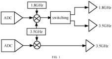
- UL Tx refers to radio frequency transmit chain (Tx chain).
- Tx chain radio frequency transmit chain
- ADC analog to digital converter
- Tx chain For one or two Tx chains associated with a certain frequency band, actual uplink transmission does not necessarily occur, depending on actual scheduling or configuration.
- the terminal supports UL Tx switching among four bands, and a correspondence between Tx chain and band may be as shown in Table 1.
- the base station cannot distinguish whether the Tx chain on the terminal side belongs to case 1 or case 2, resulting in inconsistent understanding between the base station side and the terminal side.
- the terminal only supports UL Tx switching between two bands, and supports three scenarios including Evolved Universal Terrestrial Radio Access-New Radio and Dual Connectivity (E-UTRA-NR Dual Connectivity, EN-DC), Inter-band carrier aggregation (CA) and supplementary uplink (SUL) as shown in FIG. 2A to FIG. 2C .
- E-UTRA-NR Dual Connectivity EN-DC
- CA Inter-band carrier aggregation
- SUL supplementary uplink
- RRC Radio Resource Control
- the current protocol of schemes only supports UL Tx switching among two bands.
- UL Tx switching among more than two bands needs to be studied.
- the terminal supports switching of two UL Tx among 4 bands, there are 10 different association relationships between Tx chains and frequency band pair (the frequency band pair may include one or two of the 4 bands) as shown in Table 2. There are many different actual transmission situations for each association relationship.
- 1p+0p+0p+0p means that the terminal uses a single port for transmission only in band#1
- 0p+1p+0p+0p means that the terminal uses a single port for transmission only in band#2
- 1p+1p+0p+0p means that the terminal uses single ports for transmissions respectively in band#1 and band#2 at the same time.
- the base station and the terminal may have inconsistent understanding of the correspondence between the corresponding Tx chains and the bands. Situations where inconsistent understandings regarding Table 2 are likely to occur are listed below:
- the base station cannot determine whether the Tx chain on the terminal side needs to be switched, and cannot determine whether a switching gap is needed between two adjacent uplink transmissions of the terminal, which causes inconsistent understanding between the terminal and the base station.
- the two adjacent transmissions in this present disclosure may refer to a current transmission actually to be transmitted and a previous transmission immediately adjacent to the current transmission.
- Different transmissions correspond to different resource scheduling and are not limited to being immediately adjacent in the time domain.
- the present disclosure provides the following uplink transmission method.
- the uplink transmission method provided by the present disclosure will be first introduced below from the side of the terminal.
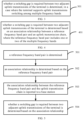
- FIG. 3 is a flow chart of an uplink transmission method according to an embodiment, which may be applied to a terminal. The method may include the following steps.
- step 301 whether a switching gap is required between two adjacent uplink transmissions of the terminal is determined, in a case where the terminal supports uplink transmissions switching among multiple frequency bands, where a total number of the multiple frequency bands is greater than 2.
- multiple frequency bands are frequency bands where the terminal supports uplink transmission switching.
- the total number of multiple frequency bands may be a positive integer greater than 2, such as 3, 4, 5..., which is not limited by the present disclosure.
- the terminal may determine whether a switching gap is required between two adjacent uplink transmissions of the terminal based on indication transmitted by a base station or based on protocol agreement.
- the terminal and the base station can determine whether the switching gap is required or not between the two adjacent uplink transmissions of the terminal based on the same rule, which ensures consistent understanding between the terminal and the base station, and improves the flexibility of network deployment and scheduling.
- the uplink transmission switching is enhanced and the availability is high.
- FIG. 4 is a flow chart of an uplink transmission method according to an embodiment, which may be applied to a terminal. The method may include the following steps.
- multiple frequency bands are frequency bands where the terminal supports uplink transmission switching.
- the total number of multiple frequency bands may be a positive integer greater than 2, such as 3, 4, 5..., which is not limited by the present disclosure.
- each reference frequency band pair there may be one or more reference frequency band pairs, which is not limited by the present disclosure.
- each reference frequency band pair it may include one or two of the above-mentioned multiple frequency bands.
- N 4
- M 10
- One of the multiple frequency bands included in the reference frequency band pair may correspond to any case of case 2-1 to case 2-4 in Table 2, and two of the multiple frequency bands included in the reference frequency band pair may correspond to any case of case 1-1 to case 1-6 in Table 2.
- the reference frequency band pair is composed of one or two frequency bands among the first to fourth frequency bands.
- the terminal may determine whether the switching gap is required based on indication from the base station or based on protocol agreement.
- whether a switching gap is required or not between two adjacent uplink transmissions of the terminal can be determined based on the association relationship between the reference frequency band pair and the uplink transmission chain, which ensures consistent understanding between the terminal and the base station, and improves the flexibility of network deployment and scheduling.
- the uplink transmission switching is enhanced and the availability is high.
- the above association relationship may be determined by the terminal and then reported to the base station.
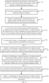
- FIG. 5 is a flow chart of an uplink transmission method according to an embodiment, which may be applied to a terminal. The method may include the following steps.
- step 501 a reference frequency band pair is determined.
- the terminal can determine the reference frequency band pair by itself according to its own situation.
- the reference frequency band pair may include one or two of the above multiple frequency bands, which is not limited in the present disclosure.
- Multiple frequency bands are frequency bands in which the terminal supports uplink transmission switching.
- the total number of multiple frequency bands may be a positive integer greater than 2, such as 3, 4, 5..., which is not limited in the present disclosure.
- the terminal can determine whether a switching gap is required based on instructions of the base station or based on protocol stipulations.
- the total number of multiple frequency bands is 4, and the terminal may determine one or more reference frequency band pairs from Table 2, which is not limited in the present disclosure.
- step 502 an association relationship is determined based on the reference frequency band pair.
- the terminal may determine the association relationship in the following manners.
- the association relationship is determined based on the first reference frequency band pair, where the first reference frequency band pair is any one frequency band pair of the reference frequency band pair(s).
- the above-mentioned association relationship may be determined by the first reference frequency band pair.
- the terminal may determine that an uplink transmission chain corresponding to the first reference frequency band pair operates in the first frequency band, and may also determine another uplink transmission chain corresponding to the first reference frequency band pair operates in a second frequency band included in the first reference frequency band pair.
- step 503 the association relationship between the reference frequency band pair and the uplink transmission chain is reported to a base station.
- step 504 whether a switching gap is required between two adjacent uplink transmissions of the terminal is determined based on the association relationship.
- the switching gap is not required between the two adjacent uplink transmissions of the terminal.
- the two adjacent uplink transmissions of the terminal are in the same frequency band, which is band#1, and band#1 belongs to any one of the previously determined reference frequency band pair(s). It is assumed that it belongs to the reference frequency band pair ⁇ band#1, band#2 ⁇ , then it is determined that the switching gap is not required between the two adjacent uplink transmissions of the terminal.
- the switching gap is not required between the two adjacent uplink transmissions of the terminal.
- the two adjacent uplink transmissions of the terminal are located in different frequency bands, which are band#1 and band#2 respectively, and band#1 and band#2 belong to the same reference frequency band pair ⁇ band#1, band#2 ⁇ determined previously. In this case, it is determined that the switching gap is not required between the two adjacent uplink transmissions of the terminal.
- the switching gap is required between the two adjacent uplink transmissions of the terminal.
- the two adjacent uplink transmissions of the terminal are in different frequency bands, which are band#1 and band#3 respectively, and the previously determined reference frequency band pair is ⁇ band#1, band#2 ⁇ , then it is determined that the switching gap is required between the two adjacent uplink transmissions of the terminal.
- the two adjacent uplink transmissions of the terminal are in the same frequency band, the same frequency band belongs to any one frequency band pair of the reference frequency band pair(s), and a correspondence between the same frequency band and the uplink transmission chain changes, then it is determined that the switching gap is required between the two adjacent uplink transmissions of the terminal.
- the terminal determines that the correspondence changes. Specifically, if the number of uplink transmission chains corresponding to the same frequency band changes from 1 to 2, or from 2 to 1, the terminal considers that the number of uplink transmission chains corresponding to the frequency band has changed, and further determines that the switching gap is required between the two adjacent uplink transmissions of the terminal.
- the two adjacent uplink transmissions of the terminal are in the same frequency band, which is band#1, and band#1 belongs to any one of the previously determined reference frequency band pair(s), for example, belongs to the reference frequency band pair ⁇ band#1, band#2 ⁇ , but the number of uplink transmission chains corresponding to band#1 changes from 1 to 2, then the terminal determines that the switching gap is required between the two adjacent uplink transmissions.
- the terminal has two reference frequency band pairs, namely ⁇ band#1, band#2 ⁇ and ⁇ band#3, band#4 ⁇ , and a previous uplink transmission of the terminal corresponds to ⁇ band#1, band#2 ⁇ .
- a to-be-performed uplink transmission corresponds to ⁇ band#3, band#4 ⁇ , it is determined that the switching gap is required between the two adjacent uplink transmissions.
- the terminal after determining the association relationship, can report it to the base station, to enable both the terminal side and the base station side to determine whether a switching gap is required or not between two adjacent uplink transmissions of the terminal based on the association relationship, which ensures consistent understanding between the terminal and the base station, and improves the flexibility of network deployment and scheduling.
- the uplink transmission switching is enhanced and the availability is high.
- the base station may transmit indication information to the terminal, where the indication information is used to indicate the reference frequency band pair, and the terminal determines the association relationship according to the reference frequency band pair.
- FIG. 6 is a flow chart of an uplink transmission method according to an embodiment, which may be applied to a terminal. The method may include the following steps.
- step 601 indication information transmitted by a base station is received, where the indication information is used to indicate a reference frequency band pair.
- the base station may transmit indication information to inform the terminal of the reference frequency band pair.
- Any one of reference frequency band pair(s) may include one or two of the above multiple frequency bands, which is not limited in the present disclosure.
- Multiple frequency bands are frequency bands where the terminal supports uplink transmission switching.
- the total number of multiple frequency bands may be a positive integer greater than 2, such as 3, 4, 5..., which is not limited in the present disclosure.
- the terminal may determine whether a switching gap is required based on instructions from base station or protocol stipulations.
- the terminal may receive the indication information transmitted by the base station through RRC signaling.
- the terminal may receive the indication information transmitted by the base station through media access control control element (MAC CE) signaling.
- MAC CE media access control control element
- step 602 an association relationship is determined based on the reference frequency band pair.
- the terminal may determine the association relationship in the following manners.
- the association relationship is determined based on the first reference frequency band pair, where the first reference frequency band pair is any one frequency band pair of the reference frequency band pair(s).
- the above-mentioned association relationship may be determined by the first reference frequency band pair.
- the terminal may determine that an uplink transmission chain corresponding to the first reference frequency band pair operates in the first frequency band, and may also determine another uplink transmission chain corresponding to the first reference frequency band pair operates in a second frequency band included in the first reference frequency band pair.
- step 603 whether a switching gap is required between two adjacent uplink transmissions of the terminal is determined based on the association relationship.
- the switching gap is not required between the two adjacent uplink transmissions of the terminal.
- the switching gap is not required between the two adjacent uplink transmissions of the terminal.
- the same frequency band belongs to any one frequency band pair of the reference frequency band pair(s), and a correspondence between the same frequency band and the uplink transmission chain changes, it is determined that the switching gap is required between the two adjacent uplink transmissions of the terminal.
- the terminal determines that the correspondence changes when the number of uplink transmission chains corresponding to the same frequency band changes. Specifically, if the number of uplink transmission chains corresponding to the same frequency band changes from 1 to 2, or from 2 to 1, the terminal considers that the number of uplink transmission chains corresponding to the frequency band has changed, and may determine that the switching gap is required between the two adjacent uplink transmissions of the terminal.
- the base station may transmit indication information to the terminal. After determining the reference frequency band pair based on the indication information, the terminal determines the association relationship, and determines whether the switching gap is required between the two adjacent uplink transmissions of the terminal based on the association relationship.
- the base station side can use the same method to determine whether the switching gap is required. In this way, consistent understanding is ensured between the terminal and the base station, and the flexibility of network deployment and scheduling is improved, achieving enhanced uplink transmission switching in the NR system, with high availability.
- the terminal can determine whether a switching gap is required between two adjacent uplink transmissions of the terminal based on the content agreed in the protocol.
- FIG. 7 is a flow chart of an uplink transmission method according to an embodiment, which may be applied to a terminal. The method may include the following steps.
- step 701 in a case where the terminal supports uplink transmission switching among multiple frequency bands, it is determined that the terminal does not expect simultaneous uplink transmissions on two or more frequency bands among the multiple frequency bands.
- multiple frequency bands are frequency bands where the terminal supports uplink transmission switching.
- the total number of multiple frequency bands may be a positive integer greater than 2, such as 3, 4, 5..., and the present disclosure does not limit thereto.
- the terminal may determine based on the protocol agreement that it does not expect to perform uplink transmission simultaneously on two or more frequency bands among the multiple frequency bands.
- step 702 it is determined whether a switching gap is required between two adjacent uplink transmissions of the terminal.
- the switching gap is required between the two adjacent uplink transmissions.
- the frequency bands in which the two adjacent uplink transmissions occur belong to multiple frequency bands.
- the frequency band where the previous uplink transmission was located is band#1
- the to-be-transmitted uplink transmission is in band#2, both of which belong to multiple frequency bands where the terminal supports uplink transmission switching. In this case, it is determined that the switching gap is required between the two adjacent uplink transmissions.
- the switching gap is required between the two adjacent uplink transmissions.
- the frequency band in which the two adjacent uplink transmissions occur belong to one of multiple frequency bands.
- the frequency band of the previous uplink transmission is band#1, and the number of ports used by it is 1; the uplink transmission to be transmitted is also in band#1, and the number of ports used by it is 2, where band#1 belongs to one of the multiple frequency bands where the terminal that supports uplink transmission switching. In this case, it is determined that the switching gap is required between the two adjacent uplink transmissions.
- the switching gap is not required between the two adjacent uplink transmissions of the terminal.
- the switching gap is not required between the two adjacent uplink transmissions of the terminal.
- the terminal can determine whether the switching gap is required between the two adjacent uplink transmissions of the terminal based on the content agreed in the protocol, and the base station can use the same method to determine whether the switching gap is required or not, which ensures consistent understanding between the terminal and the base station, and improves the flexibility of network deployment and scheduling.
- the uplink transmission switching is enhanced and the availability is high.
- the uplink transmission method provided by the present disclosure will be introduced below from the side of the base station.
- step 801 whether a switching gap is required between two adjacent uplink transmissions of a terminal is determined, in a case where the terminal supports uplink transmission switching among multiple frequency bands, where a total number of the plurality of frequency bands is greater than 2
- FIG. 9 is a flow chart of an uplink transmission method according to an embodiment, which may be applied to a base station. The method may include the following steps.
- step 901 whether a switching gap is required between two adjacent uplink transmissions of the terminal is determined based on an association relationship between a reference frequency band pair and an uplink transmission chain, where the reference frequency band pair includes one or two of multiple frequency bands.
- the terminal supports uplink transmission switching among multiple frequency bands, and the total number of multiple frequency bands is greater than 2, whether a switching gap is required or not between two adjacent uplink transmissions of the terminal can be determined based on the association relationship between the reference frequency band pair and the uplink transmission chain, which ensures consistent understanding between the terminal and the base station, and improves the flexibility of network deployment and scheduling.
- the uplink transmission switching is enhanced and the availability is high.
- the above association relationship may be determined by the terminal and then reported to the base station.
- FIG. 10 is a flow chart of an uplink transmission method according to an embodiment, which may be applied to a base station. The method may include the following steps.
- step 1001 an association relationship between a reference frequency band pair and an uplink transmission chain reported by the terminal is received.
- the terminal side may first determine a reference frequency band pair, and then determine the association relationship based on the reference frequency band pair. Further, the terminal directly reports the association relationship to the base station.
- the specific implementation is similar to the above-mentioned steps 501 to 503, which will not be described again here.
- step 1002 whether a switching gap is required between two adjacent uplink transmissions of a terminal is determined based on the association relationship.
- the terminal after determining the association relationship, can report it to the base station, to enable both the terminal side and the base station side to determine whether a switching gap is required or not between two adjacent uplink transmissions of the terminal based on the association relationship, which ensures consistent understanding between the terminal and the base station, and improves the flexibility of network deployment and scheduling.
- the uplink transmission switching is enhanced and the availability is high.
- the base station may transmit indication information to the terminal, where the indication information is used to indicate the reference frequency band pair, and the terminal determines the association relationship according to the reference frequency band pair.
- FIG. 11 is a flow chart of an uplink transmission method according to an embodiment, which may be applied to a base station.
- the method may include the following steps.
- step 1101 indication information is transmitted to a terminal, where the indication information is used to indicate a reference frequency band pair.
- the base station may transmit indication information to inform the terminal of the reference frequency band pair.
- Any one of reference frequency band pairs may include one or two of the above multiple frequency bands, which is not limited in the present disclosure.
- Multiple frequency bands are frequency bands in which the terminal supports uplink transmission switching.
- the total number of multiple frequency bands may be a positive integer greater than 2, such as 3, 4, 5..., which is not limited in the present disclosure.
- the terminal can determine whether a switching gap is required based on instructions from the base station or protocol stipulations.
- the base station may transmit the indication information to the terminal through RRC signaling.
- the base station may transmit the indication information to the terminal through MAC CE signaling.
- step 1102 the association relationship is determined based on the reference frequency band pair indicated by the indication information.
- step 1103 whether a switching gap is required between two adjacent uplink transmissions of the terminal is determined based on the association relationship.
- the way in which the base station side determines whether a switching gap is required between two adjacent uplink transmissions of the terminal is similar to the above step 603, and will not be described again here.
- the base station may transmit indication information to the terminal. After determining the reference frequency band pair based on the indication information, the terminal determines the association relationship, and determines whether the switching gap is required between the two adjacent uplink transmissions of the terminal based on the association relationship.
- the base station side can use the same method to determine whether the switching gap is required. In this way, consistent understanding is ensured between the terminal and the base station, and the flexibility of network deployment and scheduling is improved, thereby achieving enhanced uplink transmission switching in the NR system, with high availability.
- the base station may determine whether a switching gap is required between two adjacent uplink transmissions of the terminal based on the content agreed in the protocol.
- FIG. 12 is a flow chart of an uplink transmission method according to an embodiment, which may be applied to a base station. The method may include the following steps.
- step 1201 it is determined that time domain resources occupied by any two frequency bands among the multiple frequency bands do not overlap.
- the base station can determine that the time domain resources occupied by any two frequency bands among the multiple frequency bands that are not overlapped based on the agreement of a protocol.
- the base station schedules or configures uplink transmissions, the base station needs to ensure the time domain resources occupied by any two frequency bands among the multiple frequency bands not to be overlapped, thereby ensuring that the terminal side will not perform uplink transmissions simultaneously on two or more frequency bands among the multiple frequency bands.
- step 1202 whether the switching gap is required between the two adjacent uplink transmissions of the terminal is determined.
- the determination manner is similar to the above step 702, which will not be described again here.
- Tx chain and the band is illustrated by taking case 1 and case 7 as examples, as well as a transmission manner supported by each case.
- one Tx chain of the terminal operates in band#1, and the other Tx chain operates in band#2.
- 1p+0p+0p+0p means that the terminal uses a single port for uplink transmission only in band#1;
- 0p+1p+0p+0p means that the terminal uses a single port for uplink transmission only in band#2;
- 1p+1p+0p+0p means that the terminal uses single ports for uplink transmission respectively in band#1 and band#2 at the same time.
- both Tx chains of the terminal operate in band#1.
- 1p+0p+0p+0p means that the terminal uses a single port for uplink transmission only in band#1;
- 2p+0p+0p+0p means that the terminal uses dual ports for uplink transmission only in band#1.
- the same transmission scenario exists under different Tx chain operating states (case 1 to case 10), which causes the base station side to be unable to determine whether the terminal side needs to perform UL Tx switching, thus affecting scheduling decisions.
- the network side cannot determine the correspondence between the Tx chain and the band in the following transmission scenarios:
- the terminal For each of different Tx chain operating states, the terminal requires a certain switching gap to complete the hardware switching.
- the terminal may report the association relationship between N reference frequency band pairs and related uplink Tx chains.
- the reference band pair includes two bands, and the two bands included in the band pair belong to M bands where UL Tx switching is supported.
- the band combination where UL Tx switching is supported may be reported by the terminal or determined in other manners, and the present disclosure is not limited thereto.
- the switching gap is not required.
- a switching gap is not required between two adjacent uplink transmissions.
- the two adjacent uplink transmissions of the terminal are located in two different frequency bands and the two different frequency bands belong to the same frequency band pair of the reference frequency band pair(s)
- a switching gap is not required between two adjacent uplink transmissions.
- the two adjacent uplink transmissions of the terminal are located in two different frequency bands, and the two different frequency bands do not belong to the same frequency band pair of the reference frequency band pair; or, the two adjacent uplink transmissions of the terminal are located in the same frequency band, the same frequency band belongs to any one frequency band pair of the reference frequency band pairs, and a correspondence between the same frequency band and the uplink transmission chain changes (for example, changing from 1 Tx chain to 2 Tx chains, or vice versa), then a switching gap is required between two adjacent uplink transmissions of the terminal.
- the reference band pair reported by the terminal is ⁇ band#1, band#2 ⁇ , and a correspondence between a corresponding Tx chain and a band is that one Tx chain operates in band#1, and the other Tx chain operates in band#2. If the terminal scheduled by the base station meets the transmission case of the reference band pair, that is, (1p+0p+0p+0p), or (0p+1p+0p+0p), or (1p+1p+0p+0p), then the terminal does not need to perform UL Tx switching in the three scheduling scenarios.
- Embodiment 2 as described in Embodiment 1, it is assumed that the terminal reports two reference band pairs, namely ⁇ band#1, band#2 ⁇ and ⁇ band#3, band#4 ⁇ . Tx chains corresponding to the two reference band pairs reported by the terminal and uplink transmissions scenarios that can be supported simultaneously are shown in Table 5 below.
- Tx chain and the band is illustrated by taking case 1 and case 7 as examples, as well as a transmission manner supported by each case.
- one Tx chain of the terminal operates in band#1, and the other Tx chain operates in band#2.
- 1p+0p+0p+0p means that the terminal uses a single port for uplink transmission only in band#1;
- 0p+1p+0p+0p means that the terminal uses a single port for uplink transmission only in band#2;
- 1p+1p+0p+0p means that the terminal uses single ports for uplink transmission respectively in band#1 and band#2 at the same time.
- both Tx chains of the terminal operate in band#1.
- 1p+0p+0p+0p means that the terminal uses a single port for uplink transmission only in band#1;
- 2p+0p+0p+0p means that the terminal uses dual ports for uplink transmission only in band#1.
- the same transmission scenario exists under different Tx chain operating states (case 1 to case 10), which causes the base station side to be unable to determine whether the terminal side needs to perform UL Tx switching, thus affecting scheduling decisions.
- the network side cannot determine the correspondence between the Tx chain and the band in the following transmission scenarios:
- the terminal For each of different Tx chain operating states, the terminal needs a certain switching gap to complete the hardware switching.
- the base station instructs the terminal one or more reference band pairs through explicit signaling.
- Each of the reference band pair includes two bands, and the two bands included in the band pair belong to M bands where UL Tx switching is supported.
- the band combination where UL Tx switching is supported may be reported by the terminal or determined in other manners, and the present disclosure is not limited thereto.
- the switching gap is not required.
- the same frequency band belongs to any one frequency band pair of the reference frequency band pairs, and a correspondence between the same frequency band and the uplink transmission chain changes (for example, changing from 1 Tx chain to 2 Tx chains, or vice versa), then a switching gap is required between two adjacent uplink transmissions.
- the reference band pair reported by the terminal is ⁇ band#1, band#2 ⁇ , and a correspondence between a corresponding Tx chain and a band is that one Tx chain operates in band#1, and the other Tx chain operates in band#2. If the base station schedules the terminal to meet the transmission case of the reference band pair, that is, (1p+0p+0p+0p) or (0p+1p+0p+0p) or (1p+1p+0p+0p), then the terminal does not need to perform UL Tx switching in the three scheduling scenarios.
- the explicit signaling transmitted by the base station is RRC signaling or MAC CE signaling, which is not limited by the present disclosure.
- Tx chain and the band is illustrated by taking case 1 and case 7 as examples, as well as a transmission manner supported by each case.
- one Tx chain of the terminal operates in band#1, and the other Tx chain operates in band#2.
- 1p+0p+0p+0p means that the terminal uses a single port for uplink transmission only in band#1;
- 0p+1p+0p+1p means that the terminal uses a single port for uplink transmission only in band#2;
- 1p+1p+0p+0p means that the terminal uses single ports for uplink transmission respectively in band#1 and band#2 at the same time.
- both Tx chains of the terminal operate in band#1.
- 1p+0p+0p+0p means that the terminal uses a single port for uplink transmission only in band#1;
- 2p+0p+0p+0p means that the terminal uses dual ports for uplink transmission only in band#1.
- the same transmission scenario exists under different Tx chain operating states (case 1 to case 10), which causes the base station side to be unable to determine whether the terminal side needs to perform UL Tx switching, thus affecting scheduling decisions.
- the network side cannot determine the correspondence between the Tx chain and the band in the following transmission scenarios:
- the terminal For each of different Tx chain operating states, the terminal requires a certain switching gap to complete the hardware switching.
- the terminal does not expect simultaneous uplink transmission on two bands.
- the terminal can perform uplink transmission in only one band of M bands where UL Tx switching is supported.
- a UL Tx switching gap is required between the two adjacent uplink transmissions.
- the frequency bands of the two adjacent uplink transmissions belong to M bands where UL Tx switching is supported.
- a UL Tx switching gap is not required between the two adjacent uplink transmissions, where M is an integer greater than 2.
- the method regardless of the actual Tx chain state of the terminal, or the number of ports when the terminal performs uplink transmission on a certain band, as long as a band where the terminal is going to perform an uplink transmission is different from a band where an previous adjacent uplink transmission is located, it needs to assumed that a switching gap is required between the two uplink transmissions. In addition, as long as the band where the terminal is going to perform an uplink transmission is the same as the band where the previous adjacent uplink transmission is located, it is considered that a switching gap is not required between the two uplink transmissions.
- Embodiment 5 is same as described in Embodiment 4, additionally, the following predefined rule may be taken into consideration.
- the band where the terminal is going to perform an uplink transmission is the same as the band where the previous adjacent uplink transmission is located, but the numbers of ports used for the two transmissions are different. In this case, it needs to be assumed that a switching gap is required between the two uplink transmissions.
- the terminal and the base station can determine whether the switching gap is required or not between the two adjacent uplink transmissions of the terminal based on the same rule, which ensures consistent understanding between the terminal and the base station, and improves the flexibility of network deployment and scheduling.
- the uplink transmission switching is enhanced and the availability is high.
- the present disclosure further provides device embodiments for implementing the application functions.
- FIG. 13 is a block diagram of an uplink transmission device according to an exemplary embodiment.
- the device is applied to a terminal and includes:
- a first determination module 1301 configured to determine whether a switching gap is required between two adjacent uplink transmissions of the terminal, in a case where the terminal supports uplink transmission switching among a plurality of frequency bands, where a total number of the plurality of frequency bands is greater than 2.
- FIG. 14 is a block diagram of an uplink transmission device according to an exemplary embodiment.
- the apparatus is applied to a base station and includes:
- a second determination module 1401 configured to determine whether a switching gap is required between two adjacent uplink transmissions of a terminal, in a case where the terminal supports uplink transmission switching among a plurality of frequency bands, where a total number of the plurality of frequency bands is greater than 2.
- the device embodiments basically correspond to the method embodiments, the related contents can refer to part of the descriptions of the method embodiments.
- the above-described device embodiments are merely schematic, the units described above as separate components may or may not be physically separated, and the components displayed as units may or may not be physical units, i.e., the components may be located in one area or may be distributed to multiple network units. Some or all of these modules can be selected according to practical needs to achieve the purpose of the solution of the present disclosure. Those skilled in the art can understand and implement the solution without creative efforts.
- the present disclosure further provides a computer-readable storage medium.
- the computer-readable storage medium stores a computer program, and the computer program is used to execute any of the above-mentioned uplink transmission method on the side of the terminal.
- the present disclosure further provides a computer-readable storage medium.
- the computer-readable storage medium stores a computer program, and the computer program is used to execute any of the above-mentioned uplink transmission method on the side of the base station.
- an uplink transmission device including:
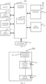
- FIG. 15 is a block diagram of an uplink transmission device 1500 according to an exemplary embodiment.
- the device 1500 may be a mobile phone, a tablet computer, an e-book reader, a multimedia playback device, a wearable device, a vehicle-mounted user equipment, an iPad, a smart TV and other terminals.
- the device 1500 may include one or more of the following components: a processing component 1502, a memory 1504, a power supply component 1506, a multimedia component 1508, an audio component 1510, an input/output (I/O) interface 1512, a sensor component 1516, and a communication component 1518.
- the processing component 1502 typically controls overall operations of the device 1500 such as the operations associated with display, telephone calls, data communications, camera operations, and recording operations.
- the processing component 1502 may include one or more processors 1520 to perform all or part of the steps in the above described method.
- the processing component 1502 may include one or more modules which facilitate the interaction between the processing component 1502 and other components.
- the processing component 1502 may include a multimedia module to facilitate the interaction between the multimedia component 1508 and the processing component 1502.
- the processing component 1502 may read executable instructions from the memory to implement steps of the uplink transmission method provided by the above embodiments.
- the memory 1504 is configured to store various types of data to support the operation of the device 1500. Examples of such data include instructions for any applications or methods operated on the device 1500, contact data, phonebook data, messages, pictures, video, etc.
- the memory 1504 may be implemented using any type of volatile or non-volatile memory devices, or a combination thereof, such as a Static Random-Access Memory (SRAM), an Electrically-Erasable Programmable Read Only Memory (EEPROM), an Erasable Programmable Read Only Memory (EPROM), a Programmable Read Only Memory (PROM), a Read Only Memory (ROM), a magnetic memory, a flash memory, a magnetic or optical disk.
- SRAM Static Random-Access Memory
- EEPROM Electrically-Erasable Programmable Read Only Memory
- EPROM Erasable Programmable Read Only Memory
- PROM Programmable Read Only Memory
- ROM Read Only Memory
- the power supply component 1506 provides power to various components of the device 1500.
- the power supply component 1506 may include a power management system, one or more power sources, and any other components associated with the generation, management, and distribution of power in the device 1500.
- the multimedia component 1508 includes a display screen providing an output interface between the device 1500 and the user.
- the multimedia component 1508 includes a front-facing camera and/or a rear-facing camera.
- the front-facing camera and/or the rear-facing camera can receive external multimedia data.
- Each front-facing camera and rear-facing camera may be a fixed optical lens system or has focal length and optical zoom capability.
- the audio component 1510 is configured to output and/or input audio signals.
- the audio component 1510 includes a microphone (MIC) configured to receive an external audio signal when the device 1500 is in an operation mode, such as a call mode, a recording mode, and a voice recognition mode.
- the received audio signal may be further stored in the memory 1504 or transmitted via the communication component 1518.
- the audio component 1510 further includes a speaker to output audio signals.
- the I/O interface 1512 provides an interface between the processing component 1502 and peripheral interface modules.
- the peripheral interface module may be a keyboard, a click wheel, buttons, and the like.
- the buttons may include, but are not limited to, a home button, a volume button, a starting button, and a locking button.
- the sensor component 1516 includes one or more sensors to provide status assessments of various aspects of the device. For instance, the sensor component 1516 may detect an on/off status of the device 1500, relative positioning of components, e.g., the display and the keypad, of the device 1500, a change in position of the device 1500 or a component of the device 1500, a presence or absence of user contact with the device 1500, an orientation or an acceleration/deceleration of the device 1500, and a change in temperature of the device 1500.
- the sensor component 1516 may include a proximity sensor configured to detect the presence of nearby objects without any physical contact.
- the sensor component 1516 may also include a light sensor, such as a Complementary Metal Oxide Semiconductor (CMOS) or Charge-Coupled Device (CCD) image sensor, for use in imaging applications.
- CMOS Complementary Metal Oxide Semiconductor
- CCD Charge-Coupled Device
- the sensor component 1516 may also include an accelerometer sensor, a gyroscope sensor, a magnetic sensor, a pressure sensor, or a temperature sensor.
- the communication component 1518 is configured to facilitate communication, wired or wirelessly, between the device 1500 and other devices.
- the device 1500 can access a wireless network based on a communication standard, such as Wi-Fi, 2G, 3G, 4G, 5G 6G, or a combination thereof.
- the communication component 1518 receives a broadcast signal or broadcast associated information from an external broadcast management system via a broadcast channel.
- the communication component 1518 further includes a Near Field Communication (NFC) module to facilitate short-range communication.
- NFC Near Field Communication
- the NFC module may be implemented based on a RF Identification (RFID) technology, an Infrared Data Association (IrDA) technology, an Ultra-Wide Band (UWB) technology, a Blue Tooth (BT) technology, and other technologies.
- RFID RF Identification
- IrDA Infrared Data Association
- UWB Ultra-Wide Band
- BT Blue Tooth
- the device 1500 may be implemented with one or more Application Specific Integrated Circuits (ASICs), Digital Signal Processors (DSPs), Digital Signal Processing Devices (DSPDs), Programmable Logic Devices (PLDs), Field Programmable Gate Arrays (FPGAs), controllers, micro-controllers, microprocessors or other electronic components, for performing any of the above uplink transmission method on the side of the terminal.
- ASICs Application Specific Integrated Circuits
- DSPs Digital Signal Processors
- DSPDs Digital Signal Processing Devices
- PLDs Programmable Logic Devices
- FPGAs Field Programmable Gate Arrays
- controllers micro-controllers, microprocessors or other electronic components, for performing any of the above uplink transmission method on the side of the terminal.
- non-transitory computer readable storage medium including executable instructions, such as the memory 1504, executable by the processor 1520 in the device 1500, for performing the above method.
- the non-transitory computer-readable storage medium may be a ROM, a Random Access Memory (RAM), a CD-ROM, a magnetic tape, a floppy disc, and an optical data storage device.
- an uplink transmission device including:
- FIG. 16 is a schematic structural diagram of an uplink transmission device 1600 according to an exemplary embodiment.
- the device 1600 may be provided as a base station.
- the device 1600 includes a processing component 1622, a wireless transmitter/receiver component 1624, an antenna component 1626, and a wireless interface-specific signal processing portion.
- the processing component 1622 may further include at least one processor.
- One of the processors in the processing component 1622 may be configured to perform any of the above-described uplink transmission method.
Landscapes
- Engineering & Computer Science (AREA)
- Signal Processing (AREA)
- Computer Networks & Wireless Communication (AREA)
- Mobile Radio Communication Systems (AREA)
Abstract
Description
- The present disclosure relates to the field of communication technologies, and provides an uplink transmission method, an uplink transmission device, and a storage medium.
- Currently, a terminal supports transmitting up to 2 transmissions (Transmit, TX) when performing uplink transmission. In the Release-18 (Rel-18) multicarrier enhancement project, it is determined to enhance uplink (UL) TX switching. Specifically, the terminal supports UL TX switching among 3 or 4 frequency bands.
- When a terminal performs UL Tx switching among multiple frequency bands, a base station may have a problem of being unable to determine whether a Tx chain on a terminal side needs to be switched, resulting in inconsistent understanding between the base station side and the terminal side.
- In order to overcome the problem existing in related technologies, embodiments of the present disclosure provide an uplink transmission method and device, and a storage medium.
- According to a first aspect, an uplink transmission method is provided according to an embodiment of the present disclosure. The method is applied to a terminal and includes:
- determining whether a switching gap is required between two adjacent uplink transmissions of the terminal, in a case where the terminal supports uplink transmission switching among a plurality of frequency bands, where a total number of the plurality of frequency bands is greater than 2.
- Optionally, the determining whether the switching gap is required between the two adjacent uplink transmissions of the terminal includes:
- determining whether the switching gap is required between the two adjacent uplink transmissions of the terminal based on an association relationship between a reference frequency band pair and an uplink transmission chain, where the reference frequency band pair includes one or two of the plurality of frequency bands.
- Optionally, the method further includes:
- determining the reference frequency band pair;
- determining the association relationship based on the reference frequency band pair; and
- reporting the association relationship to a base station.
- Optionally, the method further includes:
- receiving indication information transmitted by a base station, where the indication information is used to indicate the reference frequency band pair; and
- determining the association relationship based on the reference frequency band pair indicated by the indication information.
- Optionally, the receiving the indication information transmitted by the base station includes:
- receiving the indication information transmitted by the base station through a radio resource control (RRC) signaling; or
- receiving the indication information transmitted by the base station through a media access control control element (MAC CE) signaling.
- Optionally, the determining the association relationship includes:
determining the association relationship based on a first reference frequency band pair, in a case where an uplink transmission is performed in a first frequency band included in the first reference frequency band pair, where the first reference frequency band pair is any one frequency band pair of the reference frequency band pair. - Optionally, the determining the association relationship based on the first reference frequency band pair includes:
- determining that an uplink transmission chain corresponding to the first reference frequency band pair operates in the first frequency band; and
- determining that another uplink transmission chain corresponding to the first reference frequency band pair operates in a second frequency band included in the first reference frequency band pair.
- Optionally, the determining whether the switching gap is required between the two adjacent uplink transmissions of the terminal based on the association relationship between the reference frequency band pair and the uplink transmission chain includes:
determining that the switching gap is not required between the two adjacent uplink transmissions of the terminal in a case where frequency bands in which the two adjacent uplink transmissions of the terminal are located belong to the same frequency band pair of the reference frequency band pair. - Optionally, the determining that the switching gap is not required between the two adjacent uplink transmissions of the terminal in a case where the frequency bands in which the two adjacent uplink transmissions of the terminal are located belong to the same frequency band pair of the reference frequency band pair includes:
- determining that the switching gap is not required between the two adjacent uplink transmissions of the terminal in a case where the two adjacent uplink transmissions of the terminal are located in the same frequency band, and the same frequency band belongs to any one frequency band pair of the reference frequency band pair; or
- determining that the switching gap is not required between the two adjacent uplink transmissions of the terminal in a case where the two adjacent uplink transmissions of the terminal are located in two different frequency bands, and the two different frequency bands belong to the same frequency band pair of the reference frequency band pair.
- Optionally, the determining whether the switching gap is required between the two adjacent uplink transmissions of the terminal based on the association relationship between the reference frequency band pair and the uplink transmission chain includes:
- determining that the switching gap is required between the two adjacent uplink transmissions of the terminal in a case where the two adjacent uplink transmissions of the terminal are located in two different frequency bands, and the two different frequency bands do not belong to the same frequency band pair of the reference frequency band pair; or
- determining that the switching gap is required between the two adjacent uplink transmissions of the terminal in a case where the two adjacent uplink transmissions of the terminal are located in the same frequency band, the same frequency band belongs to any one frequency band pair of the reference frequency band pair, and a correspondence between the same frequency band and the uplink transmission chain changes.
- Optionally, the method further includes:
determining that the correspondence changes in a case where a number of uplink transmission chains corresponding to the same frequency band changes. - Optionally, the determining whether the switching gap is required between the two adjacent uplink transmissions of the terminal based on the association relationship between the reference frequency band pair and the uplink transmission chain includes:
determining that the switching gap is required between the two adjacent uplink transmissions of the terminal in a case where there are a plurality of reference frequency band pairs, and a reference frequency band pair corresponding to the two adjacent uplink transmissions of the terminal changes. - Optionally, the method further includes:
determining that the terminal does not expect simultaneous uplink transmissions on two or more frequency bands among the plurality of frequency bands. - Optionally, the determining whether the switching gap is required between the two adjacent uplink transmissions of the terminal includes:
- determining that the switching gap is required between the two adjacent uplink transmissions of the terminal in a case where frequency bands for the two adjacent uplink transmissions of the terminal are different; or
- determining that the switching gap is required between the two adjacent uplink transmissions of the terminal in a case where frequency bands for the two adjacent uplink transmissions of the terminal are the same, and numbers of ports used for the two adjacent uplink transmissions are different.
- Optionally, the determining whether the switching gap is required between the two adjacent uplink transmissions of the terminal includes:
determining that the switching gap is not required between the two adjacent uplink transmissions of the terminal in a case where frequency bands for the two adjacent uplink transmissions of the terminal are the same. - Optionally, numbers of ports used for the two adjacent uplink transmissions of the terminal are the same or different.
- According to a second aspect, an uplink transmission method is provided according to an embodiment of the present disclosure. The method is applied to a base station, and includes:
determining whether a switching gap is required between two adjacent uplink transmissions of a terminal in a case where the terminal supports uplink transmission switching among a plurality of frequency bands, where a total number of the plurality of frequency bands is greater than 2. - Optionally, the determining whether the switching gap is required between the two adjacent uplink transmissions of the terminal includes:
determining whether the switching gap is required between the two adjacent uplink transmissions of the terminal based on an association relationship between a reference frequency band pair and an uplink transmission chain, where the reference frequency band pair includes one or two of the plurality of frequency bands. - Optionally, the method further includes:
receiving the association relationship reported by the terminal. - Optionally, the method further includes:
- transmitting indication information to the terminal, where the indication information is used to indicate the reference frequency band pair; and
- determining the association relationship based on the reference frequency band pair indicated by the indication information.
- Optionally, the transmitting the indication information to the terminal includes:
- transmitting the indication information to the terminal through a radio resource control (RRC) signaling; or
- transmitting the indication information to the terminal through a media access control control element (MAC CE) signaling.
- Optionally, the determining the association relationship includes:
determining the association relationship based on a first reference frequency band pair in a case where an uplink transmission is performed by the terminal through a first frequency band included in the first reference frequency band pair, where the first reference frequency band pair is any one frequency band pair of the reference frequency band pair. - Optionally, the determining the association relationship based on the first reference frequency band pair includes:
- determining that an uplink transmission chain corresponding to the first reference frequency band pair operates in the first frequency band; and
- determining that another uplink transmission chain corresponding to the first reference frequency band pair operates in a second frequency band included in the first reference frequency band pair.
- Optionally, the determining whether the switching gap is required between the two adjacent uplink transmissions of the terminal based on the association relationship between the reference frequency band pair and the uplink transmission chain includes:
determining that the switching gap is not required between the two adjacent uplink transmissions of the terminal in a case where frequency bands in which the two adjacent uplink transmissions of the terminal are located belong to the same frequency band pair of the reference frequency band pair. - Optionally, the determining that the switching gap is not required between the two adjacent uplink transmissions of the terminal in a case where the frequency bands in which the two adjacent uplink transmissions of the terminal are located belong to the same frequency band pair of the reference frequency band pair includes:
- determining that the switching gap is not required between the two adjacent uplink transmissions of the terminal in a case where the two adjacent uplink transmissions of the terminal are located in the same frequency band, and the same frequency band belongs to any one frequency band pair of the reference frequency band pair; or
- determining that the switching gap is not required between the two adjacent uplink transmissions of the terminal in a case where the two adjacent uplink transmissions of the terminal are located in two different frequency bands, and the two different frequency bands belong to the same frequency band pair of the reference frequency band pair.
- Optionally, the determining whether the switching gap is required between the two adjacent uplink transmissions of the terminal based on the association relationship between the reference frequency band pair and the uplink transmission chain includes:
- determining that the switching gap is required between the two adjacent uplink transmissions of the terminal in a case where the two adjacent uplink transmissions of the terminal are located in two different frequency bands, and the two different frequency bands do not belong to the same frequency band pair of the reference frequency band pair; or
- determining that the switching gap is required between the two adjacent uplink transmissions of the terminal in a case where the two adjacent uplink transmissions of the terminal are located in the same frequency band, the same frequency band belongs to any one frequency band pair of the reference frequency band pair, and a correspondence between the same frequency band and the uplink transmission chain changes.
- Optionally, the method further includes:
determining that the correspondence changes, in a case where a number of uplink transmission chains corresponding to the same frequency band changes. - Optionally, the determining whether the switching gap is required between the two adjacent uplink transmissions of the terminal based on the association relationship between the reference frequency band pair and the uplink transmission chain includes:
determining that the switching gap is required between the two adjacent uplink transmissions of the terminal in a case where there are a plurality of reference frequency band pairs, and a reference frequency band pair corresponding to the two adjacent uplink transmissions of the terminal changes. - Optionally, the method further includes:
determining that time domain resources occupied by any two frequency bands among the plurality of frequency bands do not overlap. - Optionally, the determining whether the switching gap is required between the two adjacent uplink transmissions of the terminal includes:
- determining that the switching gap is required between the two adjacent uplink transmissions of the terminal in a case where frequency bands for the two adjacent uplink transmissions of the terminal are different; or
- determining that the switching gap is required between the two adjacent uplink transmissions of the terminal in a case where frequency bands for the two adjacent uplink transmissions of the terminal are the same, and numbers of ports used for the two adjacent uplink transmissions are different.
- Optionally, the determining whether the switching gap is required between the two adjacent uplink transmissions of the terminal includes:
determining that the switching gap is not required between the two adjacent uplink transmissions of the terminal in a case where frequency bands for the two adjacent uplink transmissions of the terminal are the same. - Optionally, numbers of ports used for the two adjacent uplink transmissions of the terminal are the same or different.
- According to a third aspect, an uplink transmission device is provided according to an embodiment of the present disclosure. The device is applied to a terminal, and includes:
a first determination module, configured to determine whether a switching gap is required between two adjacent uplink transmissions of the terminal, in a case where the terminal supports uplink transmission switching among a plurality of frequency bands, where a total number of the plurality of frequency bands is greater than 2. - According to a fourth aspect, an uplink transmission device is provided according to an embodiment of the present disclosure. The device is applied to a base station, and includes:
a second determination module, configured to determine whether a switching gap is required between two adjacent uplink transmissions of a terminal in a case where the terminal supports uplink transmission switching among a plurality of frequency bands, where a total number of the plurality of frequency bands is greater than 2. - According to a fifth aspect, a computer-readable storage medium is provided according to an embodiment of the present disclosure. The storage medium stores a computer program, and the computer program is configured to execute any of the above uplink transmission method on the side of the terminal.
- According to a sixth aspect, a computer-readable storage medium is provided according to an embodiment of the present disclosure. The storage medium stores a computer program, and the computer program is configured to execute any of the above uplink transmission method on the side of the base station.
- According to a seventh aspect, an uplink transmission device is provided according to an embodiment of the present disclosure, including:
- a processor; and
- a memory configured to store instructions executable by the processor,
- where the processor is configured to execute any of the above uplink transmission method on the side of the terminal.
- According to an eighth aspect, an uplink transmission device is provided according to an embodiment of the present disclosure, including:
- a processor; and
- a memory configured to store instructions executable by the processor,
- where the processor is configured to execute any of the above uplink transmission method on the side of the base station.
- The technical solutions provided by the embodiments of the present disclosure may include the following beneficial effects.
- According to some embodiments of the present disclosure, in a case where the terminal supports uplink transmission switching among multiple frequency bands, and the total number of multiple frequency bands is greater than 2, the terminal and the base station can determine whether the switching gap is required or not between the two adjacent uplink transmissions of the terminal based on the same rule, which ensures consistent understanding between the terminal and the base station, and improves the flexibility of network deployment and scheduling. In the NR system, the uplink transmission switching is enhanced and the availability is high.
- It should be appreciated that the foregoing general descriptions and the following detailed descriptions are just exemplary and explanatory, and do not limit the present disclosure.
- The accompanying drawings are incorporated in and constitute a part of this specification, illustrate embodiments consistent with the present disclosure and together with the description serve to explain the principles of the present disclosure.
-
FIG. 1 is a schematic diagram of a transmission chain according to an exemplary embodiment. -
FIG. 2A is a schematic diagram of uplink transmission switching in an EN-DC scenario according to an exemplary embodiment. -
FIG. 2B is a schematic diagram of uplink transmission switching in an Inter-band CA scenario according to an exemplary embodiment. -
FIG. 2C is a schematic diagram of uplink transmission switching in an SUL scenario according to an exemplary embodiment. -
FIG. 3 is a schematic flow chart of an uplink transmission method according to an exemplary embodiment. -
FIG. 4 is a schematic flow chart of another uplink transmission method according to an exemplary embodiment. -
FIG. 5 is a schematic flow chart of another uplink transmission method according to an exemplary embodiment. -
FIG. 6 is a schematic flow chart of another uplink transmission method according to an exemplary embodiment. -
FIG. 7 is a schematic flow chart of another uplink transmission method according to an exemplary embodiment. -
FIG. 8 is a schematic flow chart of an uplink transmission method according to an exemplary embodiment. -
FIG. 9 is a schematic flow chart of another uplink transmission method according to an exemplary embodiment. -
FIG. 10 is a schematic flow chart of another uplink transmission method according to an exemplary embodiment. -
FIG. 11 is a schematic flow chart of another uplink transmission method according to an exemplary embodiment. -
FIG. 12 is a schematic flow chart of another uplink transmission method according to an exemplary embodiment. -
FIG. 13 is a block diagram of an uplink transmission device according to an exemplary embodiment. -
FIG. 14 is a block diagram of another uplink transmission device according to an exemplary embodiment. -
FIG. 15 is a schematic structural diagram of an uplink transmission device according to an exemplary embodiment of the present disclosure. -
FIG. 16 is a schematic structural diagram of another uplink transmission device according to an exemplary embodiment of the present disclosure. - Exemplary embodiments will be described in detail herein, examples of which are illustrated in the accompanying drawings. When the following description refers to the drawings, the same reference numbers in different drawings refer to the same or similar elements unless otherwise indicated. The implementations described in the following exemplary embodiments do not represent all implementations consistent with the present disclosure. Rather, they are merely examples of device and methods consistent with some aspects of the present disclosure as detailed in the appended claims.
- The terminology used in the present disclosure is for the purpose of only describing particular embodiments and is not intended to limiting the present disclosure. The singular forms "a", "the", and "this" as used in the present disclosure and the appended claims are intended to include the plural forms as well, unless the context clearly dictates otherwise. It will also be appreciated that the term "and/or" as used herein refers to and includes any and all possible combinations of one or more of the associated listed items.
- It should be appreciated that although such terms as first, second and third may be used in the present disclosure to describe various information, the information should not be limited to these terms. These terms are only used to distinguish information of the same type from each other. For example, without departing from the scope of the present disclosure, the first information may also be referred to as the second information, and similarly, the second information may also be referred to as the first information. Depending on the context, for example, the word "if" as used herein may be interpreted as "when", or "in a case where", or "in response to determining".
- UL Tx refers to radio frequency transmit chain (Tx chain). For a terminal, two Tx chains can be used for uplink transmissions in the same band, or they can be used for uplink transmissions in two bands respectively. A possible hardware implementation of the Tx chain is shown in
FIG. 1 , in which each analog to digital converter (ADC) may correspond to one Tx chain. - For one or two Tx chains associated with a certain frequency band, actual uplink transmission does not necessarily occur, depending on actual scheduling or configuration. There may be a terminal that sends uplink data through a single port on a band, but a base station cannot determine whether the terminal has performed Tx switching. For example, the terminal supports UL Tx switching among four bands, and a correspondence between Tx chain and band may be as shown in Table 1.
Table 1 Case Correspondence between Tx chain and band Actual transmission (antenna port) Band# 1Band# 2Band#3 Band#4 case 11 1 0 0 (1,0,0,0) case 21 0 1 0 (1,0,0,0) - In this example, the base station cannot distinguish whether the Tx chain on the terminal side belongs to
case 1 orcase 2, resulting in inconsistent understanding between the base station side and the terminal side. - In Release-16 and Release-17, the terminal only supports UL Tx switching between two bands, and supports three scenarios including Evolved Universal Terrestrial Radio Access-New Radio and Dual Connectivity (E-UTRA-NR Dual Connectivity, EN-DC), Inter-band carrier aggregation (CA) and supplementary uplink (SUL) as shown in
FIG. 2A to FIG. 2C . 2 Tx transmissions are not supported in the EN-DC scenario. - Furthermore, two different UL Tx switching schemes are supported, namely:
- switched uplink (SwitchedUL), where the terminal does not support uplink transmissions simultaneously on two bands; and
- dual uplink (DualUL), where the terminal supports uplink transmissions simultaneously on two bands.
- The above two transmission modes are configured through Radio Resource Control (RRC) signaling.
- The current protocol of schemes only supports UL Tx switching among two bands. In the Rel-18 multicarrier enhancement project, it is determined that UL Tx switching among more than two bands needs to be studied.
- An example is given that the terminal supports switching of two UL Tx among 4 bands, there are 10 different association relationships between Tx chains and frequency band pair (the frequency band pair may include one or two of the 4 bands) as shown in Table 2. There are many different actual transmission situations for each association relationship.
Table 2 Case Band#1 Band#2 Band#3 Band#4 Association relationship (P = port) Case 1-1 1 1 0 0 1p+0p+0p+0p; 0p+1p+0p+0p; 1p+1p+0p+0p Case 1-2 1 0 1 0 1p+0p+0p+0p; 0p+0p+1p+0p; 1p+0p+1p+0p Case 1-3 1 0 0 1 1p+0p+0p+0p; 0p+0p+0p+1p; 1p+0p+0p+1p Case 1-4 0 1 1 0 0p+1p+0p+0p; 0p+0p+1p+0p; 0p+1p+1p+0p Case 1-5 0 1 0 1 0p+1p+0p+0p; 0p+0p+0p+1p; 0p+1p+0p+1p Case 1-6 0 0 1 1 0p+0p+1p+0p; 0p+0p+0p+1p; 0p+0p+1p+1p Case 2-1 2 0 0 0 1p+0p+0p+0p; 2p+0p+0p+0p; Case 2-2 0 2 0 0 0p+1p+0p+0p; 0p+2p+0p+0p; Case 2-3 0 0 2 0 0p+0p+1p+0p; 0p+0p+2p+0p; Case 2-4 0 0 0 2 0p+0p+0p+1p; 0p+0p+0p+2p; - It should be noted that, taking case 1-1 as an example, 1p+0p+0p+0p means that the terminal uses a single port for transmission only in
band# 1, 0p+1p+0p+0p means that the terminal uses a single port for transmission only inband# 2, and 1p+1p+0p+0p means that the terminal uses single ports for transmissions respectively inband# 1 andband# 2 at the same time. - However, for the specific uplink transmission scenarios mentioned above, the base station and the terminal may have inconsistent understanding of the correspondence between the corresponding Tx chains and the bands. Situations where inconsistent understandings regarding Table 2 are likely to occur are listed below:
- Case 1-1(1p+0p+0p+0p) is understood by the base station side as Case 1-2(1p+0p+0p+0p);
- Case 1-1(1p+0p+0p+0p) is understood by the base station side as Case 1-3(1p+0p+0p+0p);
- Case 1-1(0p+1p+0p+0p) is understood by the base station side as Case 1-4(0p+1p+0p+0p);
- Case 1-1(0p+1p+0p+0p) is understood by the base station side as Case 1-5(0p+1p+0p+0p);
- Case 1-2(1p+0p+0p+0p) is understood by the base station side as Case 1-3(1p+0p+0p+0p);
- Case 1-2(0p+0p+1p+0p) is understood by the base station side as Case 1-4(0p+0p+1p+0p);
- Case 1-3(0p+0p+0p+1p) is understood by the base station side as Case 1-5(0p+0p+0p+1p);
- Case 1-1(1p+0p+0p+0p) is understood by the base station side as Case 2-1(1p+0p+0p+0p);
- Case 1-1(0p+1p+0p+0p) is understood by the base station side as Case 2-2(0p+1p+0p+0p);
- Case 1-2(1p+0p+0p+0p) is understood by the base station side as Case 2-1(1p+0p+0p+0p);
- Case 1-2(0p+0p+1p+0p) is understood by the base station side as Case 2-3(0p+0p+1p+0p);
- Case 1-3(1p+0p+0p+0p) is understood by the base station side as Case 2-1(1p+0p+0p+0p);
- Case 1-3(0p+0p+0p+1p) is understood by the base station side as Case 2-4(0p+0p+0p+1p);
- Case 1-4(0p+1p+0p+0p) is understood by the base station side as Case 2-2(0p+1p+0p+0p);
- Case 1-4(0p+0p+1p+0p) is understood by the base station side as Case 2-3(0p+0p+1p+0p);
- Case 1-5(0p+1p+0p+0p) is understood by the base station side as Case 2-2(0p+1p+0p+0p);
- Case 1-5(0p+0p+0p+1p) is understood by the base station side as Case 2-2(0p+0p+0p+1p).
- It can be seen that when the terminal performs UL Tx switching among more than two bands, the base station cannot determine whether the Tx chain on the terminal side needs to be switched, and cannot determine whether a switching gap is needed between two adjacent uplink transmissions of the terminal, which causes inconsistent understanding between the terminal and the base station.
- It should be emphasized that the two adjacent transmissions in this present disclosure may refer to a current transmission actually to be transmitted and a previous transmission immediately adjacent to the current transmission. Different transmissions correspond to different resource scheduling and are not limited to being immediately adjacent in the time domain.
- In order to solve the above technical problem, the present disclosure provides the following uplink transmission method. The uplink transmission method provided by the present disclosure will be first introduced below from the side of the terminal.
- An embodiment of the present disclosure provides an uplink transmission method. Refer to
FIG. 3, FIG. 3 is a flow chart of an uplink transmission method according to an embodiment, which may be applied to a terminal. The method may include the following steps. - In
step 301, whether a switching gap is required between two adjacent uplink transmissions of the terminal is determined, in a case where the terminal supports uplink transmissions switching among multiple frequency bands, where a total number of the multiple frequency bands is greater than 2. - According to an embodiment of the present disclosure, multiple frequency bands are frequency bands where the terminal supports uplink transmission switching. The total number of multiple frequency bands may be a positive integer greater than 2, such as 3, 4, 5..., which is not limited by the present disclosure. The terminal may determine whether a switching gap is required between two adjacent uplink transmissions of the terminal based on indication transmitted by a base station or based on protocol agreement.
- In the above embodiment, when the terminal supports uplink transmission switching among multiple frequency bands, and the total number of multiple frequency bands is greater than 2, the terminal and the base station can determine whether the switching gap is required or not between the two adjacent uplink transmissions of the terminal based on the same rule, which ensures consistent understanding between the terminal and the base station, and improves the flexibility of network deployment and scheduling. In the NR system, the uplink transmission switching is enhanced and the availability is high.
- In some optional embodiments, referring to
FIG. 4, FIG. 4 is a flow chart of an uplink transmission method according to an embodiment, which may be applied to a terminal. The method may include the following steps. - In
step 401, whether a switching gap is required between two adjacent uplink transmissions of the terminal is determined based on an association relationship between a reference frequency band pair and an uplink transmission chain, where the reference frequency band pair includes one or two of the multiple frequency bands. - According to an embodiment of the present disclosure, multiple frequency bands are frequency bands where the terminal supports uplink transmission switching. The total number of multiple frequency bands may be a positive integer greater than 2, such as 3, 4, 5..., which is not limited by the present disclosure.
- According to an embodiment of the present disclosure, there may be one or more reference frequency band pairs, which is not limited by the present disclosure. For each reference frequency band pair, it may include one or two of the above-mentioned multiple frequency bands. When multiple frequency bands in which the terminal supports uplink transmission switching is determined, possible combinations for the reference frequency band pair can also be determined accordingly. It is assumed that the total number of multiple frequency bands is N, there are M possible combinations for the reference frequency band pair, where

- For example, N is 4, and the possible combinations for the reference band pair is M = 10, that is, the possible combinations are the same as the cases shown in Table 2.
- One of the multiple frequency bands included in the reference frequency band pair may correspond to any case of case 2-1 to case 2-4 in Table 2, and two of the multiple frequency bands included in the reference frequency band pair may correspond to any case of case 1-1 to case 1-6 in Table 2.
- For example, it may be determined that the reference frequency band pair is composed of one or two frequency bands among the first to fourth frequency bands.
- In some embodiments of the present disclosure, the terminal may determine whether the switching gap is required based on indication from the base station or based on protocol agreement.
- According to an embodiment, in the case where the terminal supports uplink transmission switching among multiple frequency bands, and the total number of multiple frequency bands is greater than 2, whether a switching gap is required or not between two adjacent uplink transmissions of the terminal can be determined based on the association relationship between the reference frequency band pair and the uplink transmission chain, which ensures consistent understanding between the terminal and the base station, and improves the flexibility of network deployment and scheduling. In the NR system, the uplink transmission switching is enhanced and the availability is high.
- In some optional embodiments, the above association relationship may be determined by the terminal and then reported to the base station.
- Referring to
FIG. 5, FIG. 5 is a flow chart of an uplink transmission method according to an embodiment, which may be applied to a terminal. The method may include the following steps. - In
step 501, a reference frequency band pair is determined. - According to an embodiment of the present disclosure, the terminal can determine the reference frequency band pair by itself according to its own situation. The reference frequency band pair may include one or two of the above multiple frequency bands, which is not limited in the present disclosure. Multiple frequency bands are frequency bands in which the terminal supports uplink transmission switching. The total number of multiple frequency bands may be a positive integer greater than 2, such as 3, 4, 5..., which is not limited in the present disclosure. The terminal can determine whether a switching gap is required based on instructions of the base station or based on protocol stipulations.
- For example, the total number of multiple frequency bands is 4, and the terminal may determine one or more reference frequency band pairs from Table 2, which is not limited in the present disclosure.
- In
step 502, an association relationship is determined based on the reference frequency band pair. - According to an embodiment of the present disclosure, the terminal may determine the association relationship in the following manners.
- In a case where an uplink transmission is performed in a first frequency band included in a first reference frequency band pair, the association relationship is determined based on the first reference frequency band pair, where the first reference frequency band pair is any one frequency band pair of the reference frequency band pair(s).
- That is, when an actual uplink transmission of the terminal is performed in the first frequency band in the first reference frequency band pair, the above-mentioned association relationship may be determined by the first reference frequency band pair.
- In a possible implementation, the terminal may determine that an uplink transmission chain corresponding to the first reference frequency band pair operates in the first frequency band, and may also determine another uplink transmission chain corresponding to the first reference frequency band pair operates in a second frequency band included in the first reference frequency band pair.
- For example, if an actual uplink transmission is performed in
band# 1 in the reference frequency band pair {band# 1, band#2}, then an uplink transmission chain corresponding to the reference frequency band pair {band# 1, band#2} operates inband# 1, another uplink transmission chain corresponding to the reference frequency band pair {band# 1, band#2} operates inband# 2. - In
step 503, the association relationship between the reference frequency band pair and the uplink transmission chain is reported to a base station. - In
step 504, whether a switching gap is required between two adjacent uplink transmissions of the terminal is determined based on the association relationship. - In a possible implementation, in a case where frequency bands where the two adjacent uplink transmissions of the terminal are located belong to the same frequency band pair of the reference frequency band pair(s), it is determined that the switching gap is not required between the two adjacent uplink transmissions of the terminal.
- Specifically, in a case where the two adjacent uplink transmissions of the terminal are located in the same frequency band, and the same frequency band belongs to any one frequency band pair of the reference frequency band pair(s), it is determined that the switching gap is not required between the two adjacent uplink transmissions of the terminal.
- For example, the two adjacent uplink transmissions of the terminal are in the same frequency band, which is
band# 1, andband# 1 belongs to any one of the previously determined reference frequency band pair(s). It is assumed that it belongs to the reference frequency band pair {band# 1, band#2}, then it is determined that the switching gap is not required between the two adjacent uplink transmissions of the terminal. - Specifically, in a case where the two adjacent uplink transmissions of the terminal are located in two different frequency bands, and the two different frequency bands belong to the same frequency band pair of the reference frequency band pair(s), it is determined that the switching gap is not required between the two adjacent uplink transmissions of the terminal.
- For example, the two adjacent uplink transmissions of the terminal are located in different frequency bands, which are
band# 1 andband# 2 respectively, andband# 1 andband# 2 belong to the same reference frequency band pair {band# 1, band#2} determined previously. In this case, it is determined that the switching gap is not required between the two adjacent uplink transmissions of the terminal. - In another possible implementation, in a case where the two adjacent uplink transmissions of the terminal are located in two different frequency bands, and the two different frequency bands do not belong to the same frequency band pair of the reference frequency band pair(s), it is determined that the switching gap is required between the two adjacent uplink transmissions of the terminal.
- For example, in a case where the two adjacent uplink transmissions of the terminal are in different frequency bands, which are
band# 1 and band#3 respectively, and the previously determined reference frequency band pair is {band# 1, band#2}, then it is determined that the switching gap is required between the two adjacent uplink transmissions of the terminal. - In another possible implementation, the two adjacent uplink transmissions of the terminal are in the same frequency band, the same frequency band belongs to any one frequency band pair of the reference frequency band pair(s), and a correspondence between the same frequency band and the uplink transmission chain changes, then it is determined that the switching gap is required between the two adjacent uplink transmissions of the terminal.
- In a case where a number of uplink transmission chains corresponding to the same frequency band changes, the terminal determines that the correspondence changes. Specifically, if the number of uplink transmission chains corresponding to the same frequency band changes from 1 to 2, or from 2 to 1, the terminal considers that the number of uplink transmission chains corresponding to the frequency band has changed, and further determines that the switching gap is required between the two adjacent uplink transmissions of the terminal.
- For example, the two adjacent uplink transmissions of the terminal are in the same frequency band, which is
band# 1, andband# 1 belongs to any one of the previously determined reference frequency band pair(s), for example, belongs to the reference frequency band pair {band# 1, band#2}, but the number of uplink transmission chains corresponding toband# 1 changes from 1 to 2, then the terminal determines that the switching gap is required between the two adjacent uplink transmissions. - In another possible implementation, in a case where there are multiple reference frequency band pairs, and a reference frequency band pair corresponding to the two adjacent uplink transmissions of the terminal changes, it is determined that the switching gap is required between the two adjacent uplink transmissions of the terminal.
- For example, the terminal has two reference frequency band pairs, namely {
band# 1, band#2} and {band#3, band#4}, and a previous uplink transmission of the terminal corresponds to {band# 1, band#2}. In a case where a to-be-performed uplink transmission corresponds to {band#3, band#4}, it is determined that the switching gap is required between the two adjacent uplink transmissions. - In the above embodiments, after determining the association relationship, the terminal can report it to the base station, to enable both the terminal side and the base station side to determine whether a switching gap is required or not between two adjacent uplink transmissions of the terminal based on the association relationship, which ensures consistent understanding between the terminal and the base station, and improves the flexibility of network deployment and scheduling. In the NR system, the uplink transmission switching is enhanced and the availability is high.
- In some optional embodiments, the base station may transmit indication information to the terminal, where the indication information is used to indicate the reference frequency band pair, and the terminal determines the association relationship according to the reference frequency band pair.
- Referring to
FIG. 6, FIG. 6 is a flow chart of an uplink transmission method according to an embodiment, which may be applied to a terminal. The method may include the following steps. - In
step 601, indication information transmitted by a base station is received, where the indication information is used to indicate a reference frequency band pair. - According to an embodiment of the present disclosure, the base station may transmit indication information to inform the terminal of the reference frequency band pair. Any one of reference frequency band pair(s) may include one or two of the above multiple frequency bands, which is not limited in the present disclosure. Multiple frequency bands are frequency bands where the terminal supports uplink transmission switching. The total number of multiple frequency bands may be a positive integer greater than 2, such as 3, 4, 5..., which is not limited in the present disclosure. The terminal may determine whether a switching gap is required based on instructions from base station or protocol stipulations.
- In a possible implementation, the terminal may receive the indication information transmitted by the base station through RRC signaling.
- In another possible implementation, the terminal may receive the indication information transmitted by the base station through media access control control element (MAC CE) signaling.
- In
step 602, an association relationship is determined based on the reference frequency band pair. - In an embodiment of the present disclosure, the terminal may determine the association relationship in the following manners.
- In a case where an uplink transmission is performed in a first frequency band included in the first reference frequency band pair, the association relationship is determined based on the first reference frequency band pair, where the first reference frequency band pair is any one frequency band pair of the reference frequency band pair(s).
- That is, in the case where actual uplink transmissions of the terminal are performed on the first frequency band in the first reference frequency band pair, the above-mentioned association relationship may be determined by the first reference frequency band pair.
- In a possible implementation, the terminal may determine that an uplink transmission chain corresponding to the first reference frequency band pair operates in the first frequency band, and may also determine another uplink transmission chain corresponding to the first reference frequency band pair operates in a second frequency band included in the first reference frequency band pair.
- In
step 603, whether a switching gap is required between two adjacent uplink transmissions of the terminal is determined based on the association relationship. - In a possible implementation, when frequency bands in which the two adjacent uplink transmissions of the terminal are located belong to the same frequency band pair of the reference frequency band pair(s), it is determined that the switching gap is not required between the two adjacent uplink transmissions of the terminal.
- Specifically, when the two adjacent uplink transmissions of the terminal are located in the same frequency band and the same frequency band belongs to any one frequency band pair of the reference frequency band pair(s), it is determined that the switching gap is not required between the two adjacent uplink transmissions of the terminal.
- Specifically, when the two adjacent uplink transmissions of the terminal are located in two different frequency bands, and the two different frequency bands belong to the same reference frequency band pair, it is determined that the switching gap is not required between the two adjacent uplink transmissions of the terminal.
- In another possible implementation, when the two adjacent uplink transmissions of the terminal are located in two different frequency bands, and the two different frequency bands do not belong to the same reference frequency band pair, it is determined that the switching gap is required between the two adjacent uplink transmissions of the terminal.
- In another possible implementation, when the two adjacent uplink transmissions of the terminal are located in the same frequency band, the same frequency band belongs to any one frequency band pair of the reference frequency band pair(s), and a correspondence between the same frequency band and the uplink transmission chain changes, it is determined that the switching gap is required between the two adjacent uplink transmissions of the terminal.
- The terminal determines that the correspondence changes when the number of uplink transmission chains corresponding to the same frequency band changes. Specifically, if the number of uplink transmission chains corresponding to the same frequency band changes from 1 to 2, or from 2 to 1, the terminal considers that the number of uplink transmission chains corresponding to the frequency band has changed, and may determine that the switching gap is required between the two adjacent uplink transmissions of the terminal.
- In another possible implementation, in a case where there are multiple reference frequency band pairs, when a reference frequency band pair corresponding to two adjacent uplink transmissions of the terminal changes, it is determined that the switching gap is required between the two adjacent uplink transmissions of the terminal.
- In the above embodiment, the base station may transmit indication information to the terminal. After determining the reference frequency band pair based on the indication information, the terminal determines the association relationship, and determines whether the switching gap is required between the two adjacent uplink transmissions of the terminal based on the association relationship. The base station side can use the same method to determine whether the switching gap is required. In this way, consistent understanding is ensured between the terminal and the base station, and the flexibility of network deployment and scheduling is improved, achieving enhanced uplink transmission switching in the NR system, with high availability.
- In some optional embodiments, the terminal can determine whether a switching gap is required between two adjacent uplink transmissions of the terminal based on the content agreed in the protocol.
- Referring to
FIG. 7, FIG. 7 is a flow chart of an uplink transmission method according to an embodiment, which may be applied to a terminal. The method may include the following steps. - In
step 701, in a case where the terminal supports uplink transmission switching among multiple frequency bands, it is determined that the terminal does not expect simultaneous uplink transmissions on two or more frequency bands among the multiple frequency bands. - According to an embodiment of the present disclosure, multiple frequency bands are frequency bands where the terminal supports uplink transmission switching. The total number of multiple frequency bands may be a positive integer greater than 2, such as 3, 4, 5..., and the present disclosure does not limit thereto.
- According to an embodiment of the present disclosure, the terminal may determine based on the protocol agreement that it does not expect to perform uplink transmission simultaneously on two or more frequency bands among the multiple frequency bands.
- In
step 702, it is determined whether a switching gap is required between two adjacent uplink transmissions of the terminal. - In a possible implementation, in a case where frequency bands of the two adjacent uplink transmissions of the terminal are different, it is determined that the switching gap is required between the two adjacent uplink transmissions of the terminal.
- That is, in a case where a frequency band of an uplink transmission to be transmitted by the terminal is different from a frequency band of a previous uplink transmission, the switching gap is required between the two adjacent uplink transmissions.
- Of course, the frequency bands in which the two adjacent uplink transmissions occur belong to multiple frequency bands.
- For example, the frequency band where the previous uplink transmission was located is
band# 1, and the to-be-transmitted uplink transmission is inband# 2, both of which belong to multiple frequency bands where the terminal supports uplink transmission switching. In this case, it is determined that the switching gap is required between the two adjacent uplink transmissions. - In another possible implementation, in a case where frequency bands for the two adjacent uplink transmissions of the terminal are the same, and numbers of ports used for the two adjacent uplink transmissions are different, it is determined that the switching gap is required between the two adjacent uplink transmissions.
- That is, in a case where a frequency band of the uplink transmission to be transmitted by the terminal is the same as a frequency band of the previous uplink transmission, but the numbers of ports used by the two transmissions are different, the switching gap is required between the two adjacent uplink transmissions. Of course, the frequency band in which the two adjacent uplink transmissions occur belong to one of multiple frequency bands.
- For example, the frequency band of the previous uplink transmission is
band# 1, and the number of ports used by it is 1; the uplink transmission to be transmitted is also inband# 1, and the number of ports used by it is 2, whereband# 1 belongs to one of the multiple frequency bands where the terminal that supports uplink transmission switching. In this case, it is determined that the switching gap is required between the two adjacent uplink transmissions. - In another possible implementation, in a case where the frequency bands of the two adjacent uplink transmissions of the terminal are the same, it is determined that the switching gap is not required between the two adjacent uplink transmissions of the terminal.
- Specifically, in a case where the frequency bands of two adjacent uplink transmissions of the terminal are the same and the numbers of ports used by both are the same, it is determined that the switching gap is not required between the two adjacent uplink transmissions of the terminal.
- Alternatively, in a case where the frequency bands of two adjacent uplink transmissions of the terminal are the same and the numbers of ports used by both are different, it is determined that the switching gap is not required between the two adjacent uplink transmissions of the terminal.
- In the above embodiments, the terminal can determine whether the switching gap is required between the two adjacent uplink transmissions of the terminal based on the content agreed in the protocol, and the base station can use the same method to determine whether the switching gap is required or not, which ensures consistent understanding between the terminal and the base station, and improves the flexibility of network deployment and scheduling. In the NR system, the uplink transmission switching is enhanced and the availability is high.
- The uplink transmission method provided by the present disclosure will be introduced below from the side of the base station.
- An embodiment of the present disclosure provides an uplink transmission method. Refer to
FIG. 8, FIG. 8 is a flow chart of an uplink transmission method according to an embodiment. It may be applied to a base station. The method may include the following steps. - In
step 801, whether a switching gap is required between two adjacent uplink transmissions of a terminal is determined, in a case where the terminal supports uplink transmission switching among multiple frequency bands, where a total number of the plurality of frequency bands is greater than 2 - According to an embodiment of the present disclosure, multiple frequency bands are frequency bands where the terminal supports uplink transmission switching. The total number of multiple frequency bands may be a positive integer greater than 2, such as 3, 4, 5..., which is not limited by the present disclosure. The base station may determine whether a switching gap is required between two adjacent uplink transmissions of the terminal based on indication transmitted to the terminal or based on protocol agreement.
- In the above embodiment, in a case where the terminal supports uplink transmission switching among multiple frequency bands, and the total number of multiple frequency bands is greater than 2, the terminal and the base station can determine whether the switching gap is required or not between the two adjacent uplink transmissions of the terminal based on the same rule, which ensures consistent understanding between the terminal and the base station, and improves the flexibility of network deployment and scheduling. In the NR system, the uplink transmission switching is enhanced and the availability is high.
- In some optional embodiments, reference is made to
FIG. 9 , which is a flow chart of an uplink transmission method according to an embodiment, which may be applied to a base station. The method may include the following steps. - In
step 901, whether a switching gap is required between two adjacent uplink transmissions of the terminal is determined based on an association relationship between a reference frequency band pair and an uplink transmission chain, where the reference frequency band pair includes one or two of multiple frequency bands. - The specific implementation is similar to the implementation provided by the embodiment shown in
FIG. 4 on the side of the terminal, and will not be described again here. - In the above embodiments, in the case where the terminal supports uplink transmission switching among multiple frequency bands, and the total number of multiple frequency bands is greater than 2, whether a switching gap is required or not between two adjacent uplink transmissions of the terminal can be determined based on the association relationship between the reference frequency band pair and the uplink transmission chain, which ensures consistent understanding between the terminal and the base station, and improves the flexibility of network deployment and scheduling. In the NR system, the uplink transmission switching is enhanced and the availability is high.
- In some optional embodiments, the above association relationship may be determined by the terminal and then reported to the base station.
- Referring to
FIG. 10, FIG. 10 is a flow chart of an uplink transmission method according to an embodiment, which may be applied to a base station. The method may include the following steps. - In
step 1001, an association relationship between a reference frequency band pair and an uplink transmission chain reported by the terminal is received. - According to an embodiment of the present disclosure, the terminal side may first determine a reference frequency band pair, and then determine the association relationship based on the reference frequency band pair. Further, the terminal directly reports the association relationship to the base station. The specific implementation is similar to the above-mentioned
steps 501 to 503, which will not be described again here. - In step 1002, whether a switching gap is required between two adjacent uplink transmissions of a terminal is determined based on the association relationship.
- The manner of determining whether the switching gap is required or not is similar to the
above step 504, which will not be described again here. - In the above embodiment, after determining the association relationship, the terminal can report it to the base station, to enable both the terminal side and the base station side to determine whether a switching gap is required or not between two adjacent uplink transmissions of the terminal based on the association relationship, which ensures consistent understanding between the terminal and the base station, and improves the flexibility of network deployment and scheduling. In the NR system, the uplink transmission switching is enhanced and the availability is high.
- In some optional embodiments, the base station may transmit indication information to the terminal, where the indication information is used to indicate the reference frequency band pair, and the terminal determines the association relationship according to the reference frequency band pair.
- Referring to
FIG. 11, FIG. 11 is a flow chart of an uplink transmission method according to an embodiment, which may be applied to a base station. The method may include the following steps. - In
step 1101, indication information is transmitted to a terminal, where the indication information is used to indicate a reference frequency band pair. - According to an embodiment of the present disclosure, the base station may transmit indication information to inform the terminal of the reference frequency band pair. Any one of reference frequency band pairs may include one or two of the above multiple frequency bands, which is not limited in the present disclosure. Multiple frequency bands are frequency bands in which the terminal supports uplink transmission switching. The total number of multiple frequency bands may be a positive integer greater than 2, such as 3, 4, 5..., which is not limited in the present disclosure. The terminal can determine whether a switching gap is required based on instructions from the base station or protocol stipulations.
- In a possible implementation, the base station may transmit the indication information to the terminal through RRC signaling.
- In another possible implementation, the base station may transmit the indication information to the terminal through MAC CE signaling.
- In
step 1102, the association relationship is determined based on the reference frequency band pair indicated by the indication information. - The manner of the base station side determining the association relationship is similar to the above-mentioned
step 602, and will not be described again here. - In
step 1103, whether a switching gap is required between two adjacent uplink transmissions of the terminal is determined based on the association relationship. - The way in which the base station side determines whether a switching gap is required between two adjacent uplink transmissions of the terminal is similar to the
above step 603, and will not be described again here. - In the above embodiments, the base station may transmit indication information to the terminal. After determining the reference frequency band pair based on the indication information, the terminal determines the association relationship, and determines whether the switching gap is required between the two adjacent uplink transmissions of the terminal based on the association relationship. The base station side can use the same method to determine whether the switching gap is required. In this way, consistent understanding is ensured between the terminal and the base station, and the flexibility of network deployment and scheduling is improved, thereby achieving enhanced uplink transmission switching in the NR system, with high availability.
- In some optional embodiments, the base station may determine whether a switching gap is required between two adjacent uplink transmissions of the terminal based on the content agreed in the protocol.
- Referring to
FIG. 12, FIG. 12 is a flow chart of an uplink transmission method according to an embodiment, which may be applied to a base station. The method may include the following steps. - In
step 1201, it is determined that time domain resources occupied by any two frequency bands among the multiple frequency bands do not overlap. - According to an embodiment of the present disclosure, the base station can determine that the time domain resources occupied by any two frequency bands among the multiple frequency bands that are not overlapped based on the agreement of a protocol. When the base station schedules or configures uplink transmissions, the base station needs to ensure the time domain resources occupied by any two frequency bands among the multiple frequency bands not to be overlapped, thereby ensuring that the terminal side will not perform uplink transmissions simultaneously on two or more frequency bands among the multiple frequency bands.
- In
step 1202, whether the switching gap is required between the two adjacent uplink transmissions of the terminal is determined. - The determination manner is similar to the
above step 702, which will not be described again here. - In the above embodiments, consistent understanding between the terminal and the base station can be ensured, and the flexibility of network deployment and scheduling is improved, thereby achieving enhanced uplink transmission switching in the NR system with high availability.
- In order to facilitate understanding of the uplink transmission method provided by the present disclosure, the above method will be further illustrated below with examples.
- Embodiment 1: it is assumed that a terminal supports two Tx chains in hardware, that is, it can support uplink transmissions in up to two bands simultaneously. If the terminal supports UL Tx switching among N bands, in an embodiment, N=4, the terminal supports, for example, 10 correspondences between Tx chains and bands as shown in Table 3. The last column lists uplink transmission scenarios supported by the terminal under each Tx chain-band correspondence.
Table 3 Case Band#1 Band#2 Band#3 Band#4 Association relationship (P = port) Case 1 1 1 0 0 1p+0p+0p+0p; 0p+1p+0p+0p; 1p+1p+0p+0p Case 2 1 0 1 0 1p+0p+0p+0p; 0p+0p+1p+0p; 1p+0p+1p+0p Case 3 1 0 0 1 1p+0p+0p+0p; 0p+0p+0p+1p; 1p+0p+0p+1p Case 4 0 1 1 0 0p+1p+0p+0p; 0p+0p+1p+0p; 0p+1p+1p+0p Case 5 0 1 0 1 0p+1p+0p+0p; 0p+0p+0p+1p; 0p+1p+0p+1p Case 6 0 0 1 1 0p+0p+1p+0p; 0p+0p+0p+1p; 0p+0p+1p+1p Case 7 2 0 0 0 1p+0p+0p+0p; 2p+0p+0p+0p; Case 8 0 2 0 0 0p+1p+0p+0p; 0p+2p+0p+0p; Case 9 0 0 2 0 0p+0p+1p+0p; 0p+0p+2p+0p; Case 10 0 0 0 2 0p+0p+0p+1p; 0p+0p+0p+2p; - The correspondence between the Tx chain and the band is illustrated by taking
case 1 and case 7 as examples, as well as a transmission manner supported by each case. -
Case 1, one Tx chain of the terminal operates inband# 1, and the other Tx chain operates inband# 2. In specific transmission scenarios, 1p+0p+0p+0p means that the terminal uses a single port for uplink transmission only inband# 1; 0p+1p+0p+0p means that the terminal uses a single port for uplink transmission only inband# 2; 1p+1p+0p+0p means that the terminal uses single ports for uplink transmission respectively inband# 1 andband# 2 at the same time. - Case 7, both Tx chains of the terminal operate in
band# 1. In specific transmission scenarios, 1p+0p+0p+0p means that the terminal uses a single port for uplink transmission only inband# 1; 2p+0p+0p+0p means that the terminal uses dual ports for uplink transmission only inband# 1. - Based on the table summarized above, the same transmission scenario exists under different Tx chain operating states (
case 1 to case 10), which causes the base station side to be unable to determine whether the terminal side needs to perform UL Tx switching, thus affecting scheduling decisions. Specifically, the network side cannot determine the correspondence between the Tx chain and the band in the following transmission scenarios: - Case 1(1p+0p+0p+0p) → Case 2(1p+0p+0p+0p);
- Case 1(1p+0p+0p+0p) → Case 3(1p+0p+0p+0p);
- Case 1(0p+1p+0p+0p) → Case 4(0p+1p+0p+0p);
- Case 1(0p+1p+0p+0p) → Case 5(0p+1p+0p+0p);
- Case 2(1p+0p+0p+0p) → Case 3(1p+0p+0p+0p);
- Case 2(0p+0p+1p+0p) → Case 4(0p+0p+1p+0p);
- Case 3(0p+0p+0p+1p) → Case 5(0p+0p+0p+1p);
- Case 1(1p+0p+0p+0p) → Case 7(1p+0p+0p+0p);
- Case 1(0p+1p+0p+0p) → Case 8(0p+1p+0p+0p);
- Case 2(1p+0p+0p+0p) → Case 7(1p+0p+0p+0p);
- Case 2(0p+0p+1p+0p) → Case 9(0p+0p+1p+0p);
- Case 3(1p+0p+0p+0p) → Case 7(1p+0p+0p+0p);
- Case 3(0p+0p+0p+1p) → Case 10(0p+0p+0p+1p);
- Case 4(0p+1p+0p+0p) → Case 8(0p+1p+0p+0p);
- Case 4(0p+0p+1p+0p) → Case 9(0p+0p+1p+0p);
- Case 5(0p+1p+0p+0p) → Case 7(0p+1p+0p+0p);
- Case 5(0p+0p+0p+1p) → Case 10(0p+0p+0p+1p).
- For each of different Tx chain operating states, the terminal requires a certain switching gap to complete the hardware switching.
- According to an embodiment , in order to achieve consistent understanding of UL Tx switching between the terminal side and the network side, the terminal may report the association relationship between N reference frequency band pairs and related uplink Tx chains.
- In an embodiment, it is assumed that N=1, the reference band pair includes two bands, and the two bands included in the band pair belong to M bands where UL Tx switching is supported. According to an embodiment, it is assumed that M=4, and a band combination in which the terminal supports UL Tx switching is {
band# 1,band# 2, band#3, band#4}. Specifically, the band combination where UL Tx switching is supported may be reported by the terminal or determined in other manners, and the present disclosure is not limited thereto. - It is assumed that the association relationship between the reference band pair and the Tx chain reported by the terminal is
case 1, which is as shown in Table 4 below.Table 4 Case Band# 1 Band# 2Band#3 Band#4 Association relationship (P=port) Case 11 1 0 0 1p+0p+0p+0p; 0p+1p+0p+0p; 1p+1p+0p+0p - In a case where a band in which an actual UL transmission is located is included in the reference band pair, the switching gap is not required.
- Specifically, in a case where the two adjacent uplink transmissions of the terminal are located in the same frequency band, and the band belongs to any one of the reference band pairs, a switching gap is not required between two adjacent uplink transmissions. Alternatively, in a case where the two adjacent uplink transmissions of the terminal are located in two different frequency bands and the two different frequency bands belong to the same frequency band pair of the reference frequency band pair(s), a switching gap is not required between two adjacent uplink transmissions.
- In a case where the two adjacent uplink transmissions of the terminal are located in two different frequency bands, and the two different frequency bands do not belong to the same frequency band pair of the reference frequency band pair; or, the two adjacent uplink transmissions of the terminal are located in the same frequency band, the same frequency band belongs to any one frequency band pair of the reference frequency band pairs, and a correspondence between the same frequency band and the uplink transmission chain changes (for example, changing from 1 Tx chain to 2 Tx chains, or vice versa), then a switching gap is required between two adjacent uplink transmissions of the terminal.
- Based on this method, when the base station schedules the terminal to perform uplink transmission in the following scenarios, there is no need to consider the switching gap between adjacent uplink transmissions in the time domain.
- Based on the method of the embodiments, the reference band pair reported by the terminal is {
band# 1, band#2}, and a correspondence between a corresponding Tx chain and a band is that one Tx chain operates inband# 1, and the other Tx chain operates inband# 2. If the terminal scheduled by the base station meets the transmission case of the reference band pair, that is, (1p+0p+0p+0p), or (0p+1p+0p+0p), or (1p+1p+0p+0p), then the terminal does not need to perform UL Tx switching in the three scheduling scenarios. - Embodiment 2: as described in
Embodiment 1, it is assumed that the terminal reports two reference band pairs, namely {band# 1, band#2} and {band#3, band#4}. Tx chains corresponding to the two reference band pairs reported by the terminal and uplink transmissions scenarios that can be supported simultaneously are shown in Table 5 below.Table 5 Case Band# 1 Band# 2Band#3 Band#4 Association relationship (P=port) Case 11 1 0 0 1p+0p+0p+0p; 0p+1p+0p+0p; 1p+1p+0p+0p Case 6 0 0 1 1 0p+0p+1p+0p; 0p+0p+0p+1p; 0p+0p+1p+1p - In a case where an uplink transmission scheduled by the base station meets a transmission case corresponding to any one of the above reference band pairs, it is considered that the correspondence between the Tx chain and the band is determined by the reference band pair, and no switching is required.
- Of course, when
case 1 is switched to case 6, a certain switching gap is required between two adjacent uplink transmissions. Other technical details are similar to these inEmbodiment 1 and will not be described again. - Embodiment 3: it is assumed that the terminal supports two Tx chains in hardware, that is, it can support uplink transmissions in up to two bands at the same time. If the terminal supports UL Tx switching among N bands, in an embodiment, N=4, the terminal supports, for example, 10 correspondences between Tx chains and bands as shown in Table 3. The last column represents uplink transmission scenarios supported by the terminal under each Tx chain-band correspondence.
- The correspondence between the Tx chain and the band is illustrated by taking
case 1 and case 7 as examples, as well as a transmission manner supported by each case. -
Case 1, one Tx chain of the terminal operates inband# 1, and the other Tx chain operates inband# 2. In specific transmission scenarios, 1p+0p+0p+0p means that the terminal uses a single port for uplink transmission only inband# 1; 0p+1p+0p+0p means that the terminal uses a single port for uplink transmission only inband# 2; 1p+1p+0p+0p means that the terminal uses single ports for uplink transmission respectively inband# 1 andband# 2 at the same time. - Case 7, both Tx chains of the terminal operate in
band# 1. In specific transmission scenarios, 1p+0p+0p+0p means that the terminal uses a single port for uplink transmission only inband# 1; 2p+0p+0p+0p means that the terminal uses dual ports for uplink transmission only inband# 1. - Based on the table summarized above, the same transmission scenario exists under different Tx chain operating states (
case 1 to case 10), which causes the base station side to be unable to determine whether the terminal side needs to perform UL Tx switching, thus affecting scheduling decisions. Specifically, the network side cannot determine the correspondence between the Tx chain and the band in the following transmission scenarios: - Case 1(1p+0p+0p+0p) → Case 2(1p+0p+0p+0p);
- Case 1(1p+0p+0p+0p) → Case 3(1p+0p+0p+0p);
- Case 1(0p+1p+0p+0p) → Case 4(0p+1p+0p+0p);
- Case 1(0p+1p+0p+0p) → Case 5(0p+1p+0p+0p);
- Case 2(1p+0p+0p+0p) → Case 3(1p+0p+0p+0p);
- Case 2(0p+0p+1p+0p) → Case 4(0p+0p+1p+0p);
- Case 3(0p+0p+0p+1p) → Case 5(0p+0p+0p+1p);
- Case 1(1p+0p+0p+0p) → Case 7(1p+0p+0p+0p);
- Case 1(0p+1p+0p+0p) → Case 8(0p+1p+0p+0p);
- Case 2(1p+0p+0p+0p) → Case 7(1p+0p+0p+0p);
- Case 2(0p+0p+1p+0p) → Case 9(0p+0p+1p+0p);
- Case 3(1p+0p+0p+0p) → Case 7(1p+0p+0p+0p);
- Case 3(0p+0p+0p+1p) → Case 10(0p+0p+0p+1p);
- Case 4(0p+1p+0p+0p) → Case 8(0p+1p+0p+0p);
- Case 4(0p+0p+1p+0p) → Case 9(0p+0p+1p+0p);
- Case 5(0p+1p+0p+0p) → Case 7(0p+1p+0p+0p);
- Case 5(0p+0p+0p+1p) → Case 10(0p+0p+0p+1p).
- For each of different Tx chain operating states, the terminal needs a certain switching gap to complete the hardware switching.
- According to an embodiment, in order to avoid the problem of inconsistent understanding between the base station and the terminal on the operating frequency band of the Tx chain, the base station instructs the terminal one or more reference band pairs through explicit signaling. Each of the reference band pair includes two bands, and the two bands included in the band pair belong to M bands where UL Tx switching is supported. According to an embodiment, it is assumed M=4, and a band combination in which the terminal supports UL Tx switching is {
band# 1,band# 2, band#3, band#4}. Specifically, the band combination where UL Tx switching is supported may be reported by the terminal or determined in other manners, and the present disclosure is not limited thereto. - It is assumed that the association relationship between the reference band pair and the Tx chain reported by the terminal is
case 1, that is, as shown in Table 4. - In a case where an actual UL transmission is performed in a band included in the reference band pair, the switching gap is not required.
- Specifically, in a case where two adjacent uplink transmissions are located in the same frequency band, and the same frequency band belongs to any one frequency band pair of the reference frequency band pairs, then there is no need for a switching gap between the two adjacent uplink transmissions; or, in a case where two adjacent uplink transmissions are located in two different frequency bands, and the two different frequency bands belong to the same frequency band pair of the reference frequency band pairs, there is no need for a switching gap between the two adjacent uplink transmissions.
- In a case where two adjacent uplink transmissions are located are in two different frequency bands, and the two different frequency bands do not belong to the same frequency band pair of the reference frequency band pairs; or two adjacent uplink transmissions of the terminal are located are in the same frequency band, the same frequency band belongs to any one frequency band pair of the reference frequency band pairs, and a correspondence between the same frequency band and the uplink transmission chain changes (for example, changing from 1 Tx chain to 2 Tx chains, or vice versa), then a switching gap is required between two adjacent uplink transmissions.
- Based on the method, in a case where the base station schedules the terminal to perform uplink transmission in the following scenarios, there is no need to consider a switching gap between adjacent uplink transmissions in the time domain. Based on the method of the embodiments, the reference band pair reported by the terminal is {
band# 1, band#2}, and a correspondence between a corresponding Tx chain and a band is that one Tx chain operates inband# 1, and the other Tx chain operates inband# 2. If the base station schedules the terminal to meet the transmission case of the reference band pair, that is, (1p+0p+0p+0p) or (0p+1p+0p+0p) or (1p+1p+0p+0p), then the terminal does not need to perform UL Tx switching in the three scheduling scenarios. - Further, the explicit signaling transmitted by the base station is RRC signaling or MAC CE signaling, which is not limited by the present disclosure.
- Embodiment 4: it is assumed that the terminal supports two Tx chains in hardware, that is, it can support uplink transmissions in up to two bands at the same time. If the terminal supports UL Tx switching among N bands, in an embodiment, N=4, the terminal supports, for example, 10 correspondences between Tx chains and bands as shown in Table 3. The last column represents uplink transmission scenarios supported by the terminal under each Tx chain-band correspondence.
- The correspondence between the Tx chain and the band is illustrated by taking
case 1 and case 7 as examples, as well as a transmission manner supported by each case. -
Case 1, one Tx chain of the terminal operates inband# 1, and the other Tx chain operates inband# 2. In specific transmission scenarios, 1p+0p+0p+0p means that the terminal uses a single port for uplink transmission only inband# 1; 0p+1p+0p+1p means that the terminal uses a single port for uplink transmission only inband# 2; 1p+1p+0p+0p means that the terminal uses single ports for uplink transmission respectively inband# 1 andband# 2 at the same time. - Case 7, both Tx chains of the terminal operate in
band# 1. In specific transmission scenarios, 1p+0p+0p+0p means that the terminal uses a single port for uplink transmission only inband# 1; 2p+0p+0p+0p means that the terminal uses dual ports for uplink transmission only inband# 1. - Based on the table summarized above, the same transmission scenario exists under different Tx chain operating states (
case 1 to case 10), which causes the base station side to be unable to determine whether the terminal side needs to perform UL Tx switching, thus affecting scheduling decisions. Specifically, the network side cannot determine the correspondence between the Tx chain and the band in the following transmission scenarios: - Case 1(1p+0p+0p+0p) → Case 2(1p+0p+0p+0p);
- Case 1(1p+0p+0p+0p) → Case 3(1p+0p+0p+0p);
- Case 1(0p+1p+0p+0p) → Case 4(0p+1p+0p+0p);
- Case 1(0p+1p+0p+0p) → Case 5(0p+1p+0p+0p);
- Case 2(1p+0p+0p+0p) → Case 3(1p+0p+0p+0p);
- Case 2(0p+0p+1p+0p) → Case 4(0p+0p+1p+0p);
- Case 3(0p+0p+0p+1p) → Case 5(0p+0p+0p+1p);
- Case 1(1p+0p+0p+0p) → Case 7(1p+0p+0p+0p);
- Case 1(0p+1p+0p+0p) → Case 8(0p+1p+0p+0p);
- Case 2(1p+0p+0p+0p) → Case 7(1p+0p+0p+0p);
- Case 2(0p+0p+1p+0p) → Case 9(0p+0p+1p+0p);
- Case 3(1p+0p+0p+0p) → Case 7(1p+0p+0p+0p);
- Case 3(0p+0p+0p+1p) → Case 10(0p+0p+0p+1p);
- Case 4(0p+1p+0p+0p) → Case 8(0p+1p+0p+0p);
- Case 4(0p+0p+1p+0p) → Case 9(0p+0p+1p+0p);
- Case 5(0p+1p+0p+0p) → Case 7(0p+1p+0p+0p);
- Case 5(0p+0p+0p+1p) → Case 10(0p+0p+0p+1p).
- For each of different Tx chain operating states, the terminal requires a certain switching gap to complete the hardware switching.
- In order to avoid inconsistent understanding on the Tx chain state of the terminal between the base station and the terminal, a predefined manner by a protocol is adopted in the present disclosure, to ensure consistent understanding between the base station and the terminal, and the following rules are predefined.
- The terminal does not expect simultaneous uplink transmission on two bands.
- That is, the terminal can perform uplink transmission in only one band of M bands where UL Tx switching is supported.
- In a case where frequency bands of two adjacent uplink transmissions of the terminal are different, a UL Tx switching gap is required between the two adjacent uplink transmissions. The frequency bands of the two adjacent uplink transmissions belong to M bands where UL Tx switching is supported.
- In a case where frequency bands of two adjacent uplink transmissions of the terminal are the same, a UL Tx switching gap is not required between the two adjacent uplink transmissions, where M is an integer greater than 2.
- According to the method, regardless of the actual Tx chain state of the terminal, or the number of ports when the terminal performs uplink transmission on a certain band, as long as a band where the terminal is going to perform an uplink transmission is different from a band where an previous adjacent uplink transmission is located, it needs to assumed that a switching gap is required between the two uplink transmissions. In addition, as long as the band where the terminal is going to perform an uplink transmission is the same as the band where the previous adjacent uplink transmission is located, it is considered that a switching gap is not required between the two uplink transmissions.
- Embodiment 5 is same as described in Embodiment 4, additionally, the following predefined rule may be taken into consideration.
- The band where the terminal is going to perform an uplink transmission is the same as the band where the previous adjacent uplink transmission is located, but the numbers of ports used for the two transmissions are different. In this case, it needs to be assumed that a switching gap is required between the two uplink transmissions.
- In the above embodiment, in a case where the terminal supports uplink transmission switching among multiple frequency bands, and the total number of multiple frequency bands is greater than 2, the terminal and the base station can determine whether the switching gap is required or not between the two adjacent uplink transmissions of the terminal based on the same rule, which ensures consistent understanding between the terminal and the base station, and improves the flexibility of network deployment and scheduling. In the NR system, the uplink transmission switching is enhanced and the availability is high.
- Corresponding to the foregoing application functions implementing the method embodiments, the present disclosure further provides device embodiments for implementing the application functions.
- Referring to
FIG. 13, FIG. 13 is a block diagram of an uplink transmission device according to an exemplary embodiment. The device is applied to a terminal and includes: - a
first determination module 1301, configured to determine whether a switching gap is required between two adjacent uplink transmissions of the terminal, in a case where the terminal supports uplink transmission switching among a plurality of frequency bands, where a total number of the plurality of frequency bands is greater than 2. - Referring to
FIG. 14, FIG. 14 is a block diagram of an uplink transmission device according to an exemplary embodiment. The apparatus is applied to a base station and includes: - a
second determination module 1401, configured to determine whether a switching gap is required between two adjacent uplink transmissions of a terminal, in a case where the terminal supports uplink transmission switching among a plurality of frequency bands, where a total number of the plurality of frequency bands is greater than 2. - The device embodiments basically correspond to the method embodiments, the related contents can refer to part of the descriptions of the method embodiments. The above-described device embodiments are merely schematic, the units described above as separate components may or may not be physically separated, and the components displayed as units may or may not be physical units, i.e., the components may be located in one area or may be distributed to multiple network units. Some or all of these modules can be selected according to practical needs to achieve the purpose of the solution of the present disclosure. Those skilled in the art can understand and implement the solution without creative efforts.
- Correspondingly, the present disclosure further provides a computer-readable storage medium. The computer-readable storage medium stores a computer program, and the computer program is used to execute any of the above-mentioned uplink transmission method on the side of the terminal.
- Correspondingly, the present disclosure further provides a computer-readable storage medium. The computer-readable storage medium stores a computer program, and the computer program is used to execute any of the above-mentioned uplink transmission method on the side of the base station.
- Correspondingly, the present disclosure further provides an uplink transmission device, including:
- a processor; and
- a memory configured to store instructions executable by the processor,
- where the processor is configured to execute any of the above-mentioned uplink transmission method on the side of the terminal.
-
FIG. 15 is a block diagram of anuplink transmission device 1500 according to an exemplary embodiment. For example, thedevice 1500 may be a mobile phone, a tablet computer, an e-book reader, a multimedia playback device, a wearable device, a vehicle-mounted user equipment, an iPad, a smart TV and other terminals. - Referring to
FIG. 15 , thedevice 1500 may include one or more of the following components: a processing component 1502, amemory 1504, apower supply component 1506, amultimedia component 1508, anaudio component 1510, an input/output (I/O)interface 1512, asensor component 1516, and acommunication component 1518. - The processing component 1502 typically controls overall operations of the
device 1500 such as the operations associated with display, telephone calls, data communications, camera operations, and recording operations. The processing component 1502 may include one ormore processors 1520 to perform all or part of the steps in the above described method. Moreover, the processing component 1502 may include one or more modules which facilitate the interaction between the processing component 1502 and other components. For example, the processing component 1502 may include a multimedia module to facilitate the interaction between themultimedia component 1508 and the processing component 1502. For another example, the processing component 1502 may read executable instructions from the memory to implement steps of the uplink transmission method provided by the above embodiments. - The
memory 1504 is configured to store various types of data to support the operation of thedevice 1500. Examples of such data include instructions for any applications or methods operated on thedevice 1500, contact data, phonebook data, messages, pictures, video, etc. Thememory 1504 may be implemented using any type of volatile or non-volatile memory devices, or a combination thereof, such as a Static Random-Access Memory (SRAM), an Electrically-Erasable Programmable Read Only Memory (EEPROM), an Erasable Programmable Read Only Memory (EPROM), a Programmable Read Only Memory (PROM), a Read Only Memory (ROM), a magnetic memory, a flash memory, a magnetic or optical disk. - The
power supply component 1506 provides power to various components of thedevice 1500. Thepower supply component 1506 may include a power management system, one or more power sources, and any other components associated with the generation, management, and distribution of power in thedevice 1500. - The
multimedia component 1508 includes a display screen providing an output interface between thedevice 1500 and the user. In some embodiments, themultimedia component 1508 includes a front-facing camera and/or a rear-facing camera. When thedevice 1500 is in an operating mode, such as a shooting mode or a video mode, the front-facing camera and/or the rear-facing camera can receive external multimedia data. Each front-facing camera and rear-facing camera may be a fixed optical lens system or has focal length and optical zoom capability. - The
audio component 1510 is configured to output and/or input audio signals. For example, theaudio component 1510 includes a microphone (MIC) configured to receive an external audio signal when thedevice 1500 is in an operation mode, such as a call mode, a recording mode, and a voice recognition mode. The received audio signal may be further stored in thememory 1504 or transmitted via thecommunication component 1518. In some embodiments, theaudio component 1510 further includes a speaker to output audio signals. - The I/
O interface 1512 provides an interface between the processing component 1502 and peripheral interface modules. The peripheral interface module may be a keyboard, a click wheel, buttons, and the like. The buttons may include, but are not limited to, a home button, a volume button, a starting button, and a locking button. - The
sensor component 1516 includes one or more sensors to provide status assessments of various aspects of the device. For instance, thesensor component 1516 may detect an on/off status of thedevice 1500, relative positioning of components, e.g., the display and the keypad, of thedevice 1500, a change in position of thedevice 1500 or a component of thedevice 1500, a presence or absence of user contact with thedevice 1500, an orientation or an acceleration/deceleration of thedevice 1500, and a change in temperature of thedevice 1500. Thesensor component 1516 may include a proximity sensor configured to detect the presence of nearby objects without any physical contact. Thesensor component 1516 may also include a light sensor, such as a Complementary Metal Oxide Semiconductor (CMOS) or Charge-Coupled Device (CCD) image sensor, for use in imaging applications. In some embodiments, thesensor component 1516 may also include an accelerometer sensor, a gyroscope sensor, a magnetic sensor, a pressure sensor, or a temperature sensor. - The
communication component 1518 is configured to facilitate communication, wired or wirelessly, between thedevice 1500 and other devices. Thedevice 1500 can access a wireless network based on a communication standard, such as Wi-Fi, 2G, 3G, 4G, 5G 6G, or a combination thereof. In an exemplary embodiment, thecommunication component 1518 receives a broadcast signal or broadcast associated information from an external broadcast management system via a broadcast channel. In an exemplary embodiment, thecommunication component 1518 further includes a Near Field Communication (NFC) module to facilitate short-range communication. For example, the NFC module may be implemented based on a RF Identification (RFID) technology, an Infrared Data Association (IrDA) technology, an Ultra-Wide Band (UWB) technology, a Blue Tooth (BT) technology, and other technologies. - In the exemplary embodiment, the
device 1500 may be implemented with one or more Application Specific Integrated Circuits (ASICs), Digital Signal Processors (DSPs), Digital Signal Processing Devices (DSPDs), Programmable Logic Devices (PLDs), Field Programmable Gate Arrays (FPGAs), controllers, micro-controllers, microprocessors or other electronic components, for performing any of the above uplink transmission method on the side of the terminal. - In an exemplary embodiment, there is also provided a non-transitory computer readable storage medium including executable instructions, such as the
memory 1504, executable by theprocessor 1520 in thedevice 1500, for performing the above method. For example, the non-transitory computer-readable storage medium may be a ROM, a Random Access Memory (RAM), a CD-ROM, a magnetic tape, a floppy disc, and an optical data storage device. - Correspondingly, the present disclosure further provides an uplink transmission device, including:
- a processor; and
- a memory configured to store instructions executable by the processor,
- where the processor is configured to execute any of the above-mentioned uplink transmission method on the side of the base station.
- As shown in
FIG. 16, FIG. 16 is a schematic structural diagram of anuplink transmission device 1600 according to an exemplary embodiment. Thedevice 1600 may be provided as a base station. Referring toFIG. 16 , thedevice 1600 includes aprocessing component 1622, a wireless transmitter/receiver component 1624, anantenna component 1626, and a wireless interface-specific signal processing portion. Theprocessing component 1622 may further include at least one processor. - One of the processors in the
processing component 1622 may be configured to perform any of the above-described uplink transmission method. - Other embodiments of the present disclosure will be apparent to those skilled in the art from consideration of the specification and practice of the present disclosure disclosed here. The present disclosure is intended to cover any variations, uses, or adaptations of the present disclosure following the general principles thereof and to include common knowledge or conventional technical means in the technical field that are not disclosed in the present disclosure. It is intended that the specification and examples be considered as exemplary only, with a true scope and spirit of the present disclosure being indicated by the following claims.
- It will be appreciated that the present disclosure is not limited to the exact construction that has been described above and illustrated in the accompanying drawings, and that various modifications and changes can be made without departing from the scope thereof. It is intended that the scope of the present disclosure is only subjected to the appended claims.
Claims (37)
determining whether a switching gap is required between two adjacent uplink transmissions of the terminal in a case where the terminal supports uplink transmission switching among a plurality of frequency bands, wherein a total number of the plurality of frequency bands is greater than 2.
determining whether the switching gap is required between the two adjacent uplink transmissions of the terminal based on an association relationship between a reference frequency band pair and an uplink transmission chain, wherein the reference frequency band pair comprises one or two of the plurality of frequency bands.
determining the association relationship based on a first reference frequency band pair in a case where an uplink transmission is performed in a first frequency band comprised in the first reference frequency band pair, wherein the first reference frequency band pair is any one frequency band pair of the reference frequency band pair.
determining that the switching gap is not required between the two adjacent uplink transmissions of the terminal in a case where frequency bands in which the two adjacent uplink transmissions of the terminal are located belong to a same frequency band pair of the reference frequency band pair.
determining that the correspondence changes in a case where a number of uplink transmission chains corresponding to the same frequency band changes.12. (Original) The uplink transmission method according to claim 2, wherein the determining whether the switching gap is required between the two adjacent uplink transmissions of the terminal based on the association relationship between the reference frequency band pair and the uplink transmission chain comprises:
determining that the switching gap is required between the two adjacent uplink transmissions of the terminal in a case where there are a plurality of reference frequency band pairs, and a reference frequency band pair corresponding to the two adjacent uplink transmissions of the terminal changes.
determining that the terminal does not expect simultaneous uplink transmissions on two or more frequency bands among the plurality of frequency bands.
determining that the switching gap is not required between the two adjacent uplink transmissions of the terminal in a case where frequency bands for the two adjacent uplink transmissions of the terminal are the same.
determining whether a switching gap is required between two adjacent uplink transmissions of a terminal in a case where the terminal supports uplink transmission switching among a plurality of frequency bands, wherein a total number of the plurality of frequency bands is greater than 2.
determining whether the switching gap is required between the two adjacent uplink transmissions of the terminal based on an association relationship between a reference frequency band pair and an uplink transmission chain, wherein the reference frequency band pair comprises one or two of the plurality of frequency bands.
receiving the association relationship reported by the terminal.
determining the association relationship based on a first reference frequency band pair in a case where an uplink transmission is performed by the terminal through a first frequency band comprised in the first reference frequency band pair, wherein the first reference frequency band pair is any one frequency band pair of the reference frequency band pair.
determining that the switching gap is not required between the two adjacent uplink transmissions of the terminal in a case where frequency bands in which the two adjacent uplink transmissions of the terminal are located belong to a same frequency band pair of the reference frequency band pair.
determining that the correspondence changes in a case where a number of uplink transmission chains corresponding to the same frequency band changes.
determining that the switching gap is required between the two adjacent uplink transmissions of the terminal in a case where there are a plurality of reference frequency band pairs, and a reference frequency band pair corresponding to the two adjacent uplink transmissions of the terminal changes.
determining that time domain resources occupied by any two frequency bands among the plurality of frequency bands do not overlap.
determining that the switching gap is not required between the two adjacent uplink transmissions of the terminal in a case where frequency bands for the two adjacent uplink transmissions of the terminal are the same.
a first determination module, configured to determine whether a switching gap is required between two adjacent uplink transmissions of the terminal in a case where the terminal supports uplink transmission switching among a plurality of frequency bands, wherein a total number of the plurality of frequency bands is greater than 2.
a second determination module, configured to determine whether a switching gap is required between two adjacent uplink transmissions of a terminal in a case where the terminal supports uplink transmission switching among a plurality of frequency bands, wherein a total number of the plurality of frequency bands is greater than 2.
Applications Claiming Priority (1)
| Application Number | Priority Date | Filing Date | Title |
|---|---|---|---|
| PCT/CN2022/090683 WO2023206540A1 (en) | 2022-04-29 | 2022-04-29 | Uplink transmission method and device, and storage medium |
Publications (2)
| Publication Number | Publication Date |
|---|---|
| EP4518427A1 true EP4518427A1 (en) | 2025-03-05 |
| EP4518427A4 EP4518427A4 (en) | 2025-06-18 |
Family
ID=83168343
Family Applications (1)
| Application Number | Title | Priority Date | Filing Date |
|---|---|---|---|
| EP22939386.3A Pending EP4518427A4 (en) | 2022-04-29 | 2022-04-29 | UPLINK TRANSMISSION METHOD AND DEVICE, AND STORAGE MEDIUM |
Country Status (6)
| Country | Link |
|---|---|
| US (1) | US20260005823A1 (en) |
| EP (1) | EP4518427A4 (en) |
| JP (1) | JP7849505B2 (en) |
| KR (1) | KR20250005380A (en) |
| CN (2) | CN115053567B (en) |
| WO (1) | WO2023206540A1 (en) |
Families Citing this family (6)
| Publication number | Priority date | Publication date | Assignee | Title |
|---|---|---|---|---|
| WO2024065436A1 (en) * | 2022-09-29 | 2024-04-04 | Oppo广东移动通信有限公司 | Method for wireless communication, terminal device, and network device |
| CN117812720A (en) * | 2022-09-30 | 2024-04-02 | 华为技术有限公司 | A communication method and communication device |
| WO2024092645A1 (en) * | 2022-11-03 | 2024-05-10 | Apple Inc. | Ue capability reporting and configuration for dynamic ul tx switching for more than 2 bands |
| WO2024197633A1 (en) * | 2023-03-29 | 2024-10-03 | Qualcomm Incorporated | Scheduling uplink transmissions on multiple frequency bands |
| CN119012378A (en) * | 2023-05-22 | 2024-11-22 | 华为技术有限公司 | Communication method and communication device |
| CN120264446A (en) * | 2023-08-02 | 2025-07-04 | 中国电信股份有限公司技术创新中心 | Terminal capability reporting method, user terminal, communication system and storage medium |
Family Cites Families (14)
| Publication number | Priority date | Publication date | Assignee | Title |
|---|---|---|---|---|
| US10219247B2 (en) * | 2014-07-04 | 2019-02-26 | Samsung Electronics Co., Ltd. | Method and system for preventing overlap between reception and transmission by user equipment in wireless communication system |
| JP6633084B2 (en) * | 2015-08-21 | 2020-01-22 | 株式会社Nttドコモ | User terminal, wireless base station, and wireless communication method |
| WO2018126453A1 (en) * | 2017-01-06 | 2018-07-12 | 广东欧珀移动通信有限公司 | Handover method, base station, and terminal |
| JP7066748B2 (en) * | 2018-01-12 | 2022-05-13 | 株式会社Nttドコモ | Terminals, base stations, wireless communication systems, and uplink transmission timing adjustment methods |
| CN111726874B (en) * | 2018-11-19 | 2024-07-16 | 华为技术有限公司 | Uplink switching method, communication device and communication system |
| CN112449426B (en) * | 2019-09-04 | 2022-12-06 | 维沃移动通信有限公司 | Uplink transmission method and terminal |
| CN112751600B (en) * | 2019-10-31 | 2023-10-31 | 中国电信股份有限公司 | Method, base station and communication system for supporting uplink carrier multi-antenna transmission |
| WO2021127835A1 (en) * | 2019-12-23 | 2021-07-01 | Qualcomm Incorporated | Determining whether an uplink switching gap is to be applied between changes in radio frequency status of a user equipment |
| WO2021205419A1 (en) * | 2020-04-10 | 2021-10-14 | Telefonaktiebolaget Lm Ericsson (Publ) | Processing time for fast-switched ul tx across carriers |
| CN113766641B (en) * | 2020-06-01 | 2025-02-28 | 华为技术有限公司 | A communication method, device and system |
| CN113784339B (en) * | 2020-06-10 | 2023-06-02 | 华为技术有限公司 | Communication method and device |
| CN113993211B (en) * | 2020-07-27 | 2025-04-15 | 大唐移动通信设备有限公司 | A method for indicating time domain parameters of data transmission, UE and base station |
| CN114126056B (en) * | 2020-08-28 | 2026-02-03 | 华为技术有限公司 | Uplink transmission method and device |
| US12250747B2 (en) * | 2020-10-16 | 2025-03-11 | Qualcomm Incorporated | Downlink/uplink (DL/UL) switching capability reporting for systems with high subcarrier spacing (SCS) |
-
2022
- 2022-04-29 EP EP22939386.3A patent/EP4518427A4/en active Pending
- 2022-04-29 CN CN202280001425.7A patent/CN115053567B/en active Active
- 2022-04-29 CN CN202410226989.1A patent/CN118118964A/en active Pending
- 2022-04-29 JP JP2024563964A patent/JP7849505B2/en active Active
- 2022-04-29 KR KR1020247039109A patent/KR20250005380A/en active Pending
- 2022-04-29 US US18/860,892 patent/US20260005823A1/en active Pending
- 2022-04-29 WO PCT/CN2022/090683 patent/WO2023206540A1/en not_active Ceased
Also Published As
| Publication number | Publication date |
|---|---|
| JP7849505B2 (en) | 2026-04-21 |
| WO2023206540A1 (en) | 2023-11-02 |
| EP4518427A4 (en) | 2025-06-18 |
| JP2025516251A (en) | 2025-05-27 |
| KR20250005380A (en) | 2025-01-09 |
| CN115053567B (en) | 2024-03-26 |
| US20260005823A1 (en) | 2026-01-01 |
| CN115053567A (en) | 2022-09-13 |
| CN118118964A (en) | 2024-05-31 |
Similar Documents
| Publication | Publication Date | Title |
|---|---|---|
| EP4518427A1 (en) | Uplink transmission method and device, and storage medium | |
| US11540277B2 (en) | Supplementary uplink carrier configuration method and device, and scheduling resource allocation method and device | |
| US11483819B2 (en) | Data transmission method and apparatus and user equipment | |
| EP4550914A1 (en) | Resource determining method and apparatus, multi-carrier scheduling method and apparatus, and storage medium | |
| US20230275650A1 (en) | Data transmission method and apparatus based on satellite communication, and storage medium | |
| EP4550908A1 (en) | Resource determination method and apparatus, multi-carrier scheduling method and apparatus, and storage medium | |
| EP4106463A1 (en) | Transmission scheduling method and apparatus, communication device, and storage medium | |
| US11742884B2 (en) | Data transmission method and device, and communication system | |
| US20190281617A1 (en) | Method and apparatus for determining transmission time interval, base station and user equipment | |
| EP4694472A1 (en) | Information transmission method and apparatus, and storage medium | |
| EP4344108A2 (en) | Modulation and coding scheme (mcs) configuration method and apparatus, and communication device | |
| US20230413272A1 (en) | Uplink control information transmission method and apparatus, and storage medium | |
| CN114788217B (en) | Sidelink communication method and device | |
| EP4002932A1 (en) | Pusch receiving method and device, pusch sending method and device | |
| US20190132863A1 (en) | Data transmission method and device, and computer-readable storage medium | |
| EP4301063A1 (en) | Channel transmission method and device, and storage medium | |
| RU2852260C2 (en) | Method and device for uplink transmission | |
| CN114788373A (en) | Downlink control information scheduling method, device and storage medium | |
| EP4598091A1 (en) | Frequency hopping processing method and device | |
| EP4598175A1 (en) | Frequency hopping processing method and device | |
| EP4535890A1 (en) | Resource determining method and apparatus, multi-carrier scheduling method and apparatus, and storage medium | |
| EP4444003A1 (en) | Downlink control information detection method and apparatus, downlink control information sending method and apparatus, and storage medium | |
| US20240064769A1 (en) | Information transmission method and device | |
| WO2024059978A1 (en) | Information transmission method and apparatus |
Legal Events
| Date | Code | Title | Description |
|---|---|---|---|
| STAA | Information on the status of an ep patent application or granted ep patent |
Free format text: STATUS: THE INTERNATIONAL PUBLICATION HAS BEEN MADE |
|
| PUAI | Public reference made under article 153(3) epc to a published international application that has entered the european phase |
Free format text: ORIGINAL CODE: 0009012 |
|
| STAA | Information on the status of an ep patent application or granted ep patent |
Free format text: STATUS: REQUEST FOR EXAMINATION WAS MADE |
|
| 17P | Request for examination filed |
Effective date: 20241128 |
|
| AK | Designated contracting states |
Kind code of ref document: A1 Designated state(s): AL AT BE BG CH CY CZ DE DK EE ES FI FR GB GR HR HU IE IS IT LI LT LU LV MC MK MT NL NO PL PT RO RS SE SI SK SM TR |
|
| A4 | Supplementary search report drawn up and despatched |
Effective date: 20250515 |
|
| RIC1 | Information provided on ipc code assigned before grant |
Ipc: H04W 36/06 20090101ALI20250509BHEP Ipc: H04L 5/00 20060101ALI20250509BHEP Ipc: H04W 36/00 20090101AFI20250509BHEP |
|
| DAV | Request for validation of the european patent (deleted) | ||
| DAX | Request for extension of the european patent (deleted) |