EP4518351A1 - Loudspeaker - Google Patents
Loudspeaker Download PDFInfo
- Publication number
- EP4518351A1 EP4518351A1 EP22969486.4A EP22969486A EP4518351A1 EP 4518351 A1 EP4518351 A1 EP 4518351A1 EP 22969486 A EP22969486 A EP 22969486A EP 4518351 A1 EP4518351 A1 EP 4518351A1
- Authority
- EP
- European Patent Office
- Prior art keywords
- magnetic fluid
- diaphragm
- magnet
- speaker
- cavity
- Prior art date
- Legal status (The legal status is an assumption and is not a legal conclusion. Google has not performed a legal analysis and makes no representation as to the accuracy of the status listed.)
- Pending
Links
Images





Classifications
-
- H—ELECTRICITY
- H04—ELECTRIC COMMUNICATION TECHNIQUE
- H04R—LOUDSPEAKERS, MICROPHONES, GRAMOPHONE PICK-UPS OR LIKE ACOUSTIC ELECTROMECHANICAL TRANSDUCERS; ELECTRIC HEARING AIDS; PUBLIC ADDRESS SYSTEMS
- H04R7/00—Diaphragms for electromechanical transducers; Cones
- H04R7/16—Mounting or tensioning of diaphragms or cones
- H04R7/18—Mounting or tensioning of diaphragms or cones at the periphery
-
- H—ELECTRICITY
- H04—ELECTRIC COMMUNICATION TECHNIQUE
- H04R—LOUDSPEAKERS, MICROPHONES, GRAMOPHONE PICK-UPS OR LIKE ACOUSTIC ELECTROMECHANICAL TRANSDUCERS; ELECTRIC HEARING AIDS; PUBLIC ADDRESS SYSTEMS
- H04R1/00—Details of transducers, loudspeakers or microphones
- H04R1/02—Casings; Cabinets ; Supports therefor; Mountings therein
- H04R1/025—Arrangements for fixing loudspeaker transducers, e.g. in a box, furniture
-
- H—ELECTRICITY
- H04—ELECTRIC COMMUNICATION TECHNIQUE
- H04R—LOUDSPEAKERS, MICROPHONES, GRAMOPHONE PICK-UPS OR LIKE ACOUSTIC ELECTROMECHANICAL TRANSDUCERS; ELECTRIC HEARING AIDS; PUBLIC ADDRESS SYSTEMS
- H04R7/00—Diaphragms for electromechanical transducers; Cones
- H04R7/02—Diaphragms for electromechanical transducers; Cones characterised by the construction
- H04R7/04—Plane diaphragms
-
- H—ELECTRICITY
- H04—ELECTRIC COMMUNICATION TECHNIQUE
- H04R—LOUDSPEAKERS, MICROPHONES, GRAMOPHONE PICK-UPS OR LIKE ACOUSTIC ELECTROMECHANICAL TRANSDUCERS; ELECTRIC HEARING AIDS; PUBLIC ADDRESS SYSTEMS
- H04R1/00—Details of transducers, loudspeakers or microphones
- H04R1/10—Earpieces; Attachments therefor ; Earphones; Monophonic headphones
- H04R1/1008—Earpieces of the supra-aural or circum-aural type
-
- H—ELECTRICITY
- H04—ELECTRIC COMMUNICATION TECHNIQUE
- H04R—LOUDSPEAKERS, MICROPHONES, GRAMOPHONE PICK-UPS OR LIKE ACOUSTIC ELECTROMECHANICAL TRANSDUCERS; ELECTRIC HEARING AIDS; PUBLIC ADDRESS SYSTEMS
- H04R1/00—Details of transducers, loudspeakers or microphones
- H04R1/10—Earpieces; Attachments therefor ; Earphones; Monophonic headphones
- H04R1/1016—Earpieces of the intra-aural type
-
- H—ELECTRICITY
- H04—ELECTRIC COMMUNICATION TECHNIQUE
- H04R—LOUDSPEAKERS, MICROPHONES, GRAMOPHONE PICK-UPS OR LIKE ACOUSTIC ELECTROMECHANICAL TRANSDUCERS; ELECTRIC HEARING AIDS; PUBLIC ADDRESS SYSTEMS
- H04R17/00—Piezoelectric transducers; Electrostrictive transducers
-
- H—ELECTRICITY
- H04—ELECTRIC COMMUNICATION TECHNIQUE
- H04R—LOUDSPEAKERS, MICROPHONES, GRAMOPHONE PICK-UPS OR LIKE ACOUSTIC ELECTROMECHANICAL TRANSDUCERS; ELECTRIC HEARING AIDS; PUBLIC ADDRESS SYSTEMS
- H04R2307/00—Details of diaphragms or cones for electromechanical transducers, their suspension or their manufacture covered by H04R7/00 or H04R31/003, not provided for in any of its subgroups
- H04R2307/204—Material aspects of the outer suspension of loudspeaker diaphragms
-
- H—ELECTRICITY
- H04—ELECTRIC COMMUNICATION TECHNIQUE
- H04R—LOUDSPEAKERS, MICROPHONES, GRAMOPHONE PICK-UPS OR LIKE ACOUSTIC ELECTROMECHANICAL TRANSDUCERS; ELECTRIC HEARING AIDS; PUBLIC ADDRESS SYSTEMS
- H04R7/00—Diaphragms for electromechanical transducers; Cones
- H04R7/16—Mounting or tensioning of diaphragms or cones
- H04R7/18—Mounting or tensioning of diaphragms or cones at the periphery
- H04R7/20—Securing diaphragm or cone resiliently to support by flexible material, springs, cords, or strands
-
- H—ELECTRICITY
- H04—ELECTRIC COMMUNICATION TECHNIQUE
- H04R—LOUDSPEAKERS, MICROPHONES, GRAMOPHONE PICK-UPS OR LIKE ACOUSTIC ELECTROMECHANICAL TRANSDUCERS; ELECTRIC HEARING AIDS; PUBLIC ADDRESS SYSTEMS
- H04R9/00—Transducers of moving-coil, moving-strip, or moving-wire type
- H04R9/06—Loudspeakers
Definitions
- the present disclosure relates to the field of acoustic technology, and in particular, to a speaker.
- an edge of a diaphragm of the speaker is usually fixedly connected to a shell of the speaker.
- the deformation of the center region of the diaphragm is also limited by the region where the fixed edge is located, thus reducing a volume of air pushed by the diaphragm (also known as an air push volume), which has a negative impact on the performance of the speaker, in particular, impacts the low frequency performance of the speaker requiring a great displacement and a great air push volume.
- a volume of air pushed by the diaphragm also known as an air push volume
- the shell includes a magnet
- the sliding connection portion is a magnetic fluid
- a surface of the magnet forms at least a portion of the inner wall of the cavity
- the diaphragm drives the magnetic fluid to slide on the surface of the magnet
- the sliding connection section includes a magnet and a magnetic fluid.
- the magnet is connected to the diaphragm, and the magnetic fluid is configured to connect the magnet to the inner wall of the cavity.
- the magnetic fluid slides with the magnet relative to the inner wall of the shell by a magnetic force between the magnetic fluid and the magnet.
- a carrier liquid of the magnetic fluid is an aqueous liquid or an oily liquid
- a material of the inner wall of the cavity within a sliding range of the magnetic fluid is a first surface material
- a material of the inner wall of the cavity outside the sliding range of the magnetic fluid is a second surface material.
- a property of the carrier liquid is the same as a hydrophilic or lipophilic property of the first surface material, and the first surface material and the second surface material have opposite hydrophilic or lipophilic properties.
- the shell includes a first magnet
- the sliding connection portion includes a second magnet and a magnetic fluid.
- a surface of the first magnet forms at least a portion of the inner wall of the cavity
- the second magnet is connected to the diaphragm
- the magnetic fluid is configured to connect the first magnet to the second magnet, and the diaphragm drives, through the second magnet, the magnetic fluid to slide on the surface of the first magnet.
- the first magnet and the second magnet are arranged with the same magnetic poles facing each other.
- the speaker further includes a magnetic fluid constraint structure configured to constrain a position of the magnetic fluid.
- the magnetic fluid constraint structure includes a first magnetic fluid constraint element and a second magnetic fluid restraint element that are disposed on the diaphragm, the first magnetic fluid restraint element and the second magnetic fluid constraint element being provided to be located on opposite sides of the magnetic fluid along a vibration direction of the diaphragm, respectively.
- the first magnetic fluid constraint element and the second magnetic fluid restraint element are disposed on the inner wall of the cavity and located outside the sliding range of the magnetic fluid.
- a distance between the first magnetic fluid constraint element and an edge of the sliding range is within a first distance threshold range
- a distance between the second magnetic fluid constraint element and the edge of the sliding range is within a second distance threshold range.
- the property of the carrier liquid of the magnetic fluid is the same as or opposite to the hydrophilic or lipophilic property of the surface material of the magnetic fluid constraint structure.
- the sliding connection portion is a fluid, wherein the material of the inner wall of the cavity within the sliding range of the fluid is a first surface material, and the material of the inner wall of the cavity outside the sliding range of the fluid is a second surface material, wherein the fluid has the same hydrophilic or lipophilic property as the first surface material, and the first surface material has opposite hydrophilic or lipophilic property as the second surface material.
- the fluid is a viscous fluid with a kinematic viscosity greater than 100 cst.
- the cavity is disposed with a concave or convex structure within a region on the inner wall of the cavity contacting the fluid.
- a size of the concave or convex structure on a surface of the inner wall of the cavity along a vibration direction of the diaphragm is in a range of 0.2 ⁇ m-200 ⁇ m, and a size of the concave or convex structure along a direction perpendicular to the inner wall of the cavity is in a range of 0.2 ⁇ m-200 ⁇ m.
- the diaphragm is a flat plate structure.
- first,” “second,” “third,” “fourth,” etc. are used for descriptive purposes only, and are not to be understood as indicating or implying relative importance or implicitly specifying the number of technical features indicated. Thereby, the limitations “first,” “second,” “third,” and “fourth” expressly or implicitly include at least one such feature.
- “plurality” means at least two, e.g., two, three, etc., unless otherwise expressly and specifically limited.
- connection refers to a fixed connection, a removable connection, or an integrated connection; a mechanical connection, or an electrical connection; a direct connection, or an indirect connection through an intermediate medium, a connection within two elements, or an interaction between two elements, unless expressly limited otherwise.
- connection refers to a fixed connection, a removable connection, or an integrated connection; a mechanical connection, or an electrical connection; a direct connection, or an indirect connection through an intermediate medium, a connection within two elements, or an interaction between two elements, unless expressly limited otherwise.
- connection refers to a fixed connection, a removable connection, or an integrated connection; a mechanical connection, or an electrical connection; a direct connection, or an indirect connection through an intermediate medium, a connection within two elements, or an interaction between two elements, unless expressly limited otherwise.
- the present disclosure provides a speaker including a shell, a diaphragm, and a sliding connection portion.
- the shell includes a cavity.
- the diaphragm is accommodated within the cavity, which separates the cavity to form at least two sub-cavities.
- the diaphragm is driven by an electrical signal to vibrate relative to the shell to generate sound.
- the sliding connection portion is configured to connect an edge of the diaphragm to an inner wall of the cavity. The sliding connection portion allows the edge of the diaphragm to slide relative to the inner wall of the shell, so that the diaphragm as a whole is able to displace relative to the inner wall of the shell.
- the diaphragm as a whole makes a piston-like movement relative to the inner wall of the shell, which allows the diaphragm to generate a greater displacement, push more air, and thereby improving the performance of the speaker, especially the sensitivity of the speaker at a low frequency range.
- FIG. 1 is a block diagram illustrating a structure of an exemplary speaker according to some embodiments of the present disclosure.
- a speaker 100 includes a piezoelectric speaker (as shown in FIG. 2A ), an electromagnetic speaker (as shown in FIG. 2B ), a moving iron speaker, an electrostatic speaker, etc., or any combination thereof.
- the speaker 100 includes a shell 110, a diaphragm 120, and a sliding connection portion 130.
- the shell 110 is configured to carry other components of the speaker 100 (e.g., the diaphragm 120, the sliding connection portion 130, etc.).
- the shell 110 has a cavity.
- One or more components of the speaker 100 are disposed within the cavity.
- the shell 110 is a regular or irregular three-dimensional (3D) structure such as a cuboid, a cylinder, etc.
- 3D three-dimensional
- the shell 110 is located near a user's ear.
- the shell 110 is located on a circumferential side (e.g., a front side or a rear side) of the user's ear.
- the shell 110 is disposed over the user's ear without blocking or covering the user's ear canal.
- the shell 110 is partially disposed within the user's ear canal.
- at least one sound outlet is included in the shell 110, and a sound generated by vibration of the diaphragm 120 is radiated in a direction to the user's ear through the sound outlet.
- the diaphragm 120 is disposed within the cavity of the shell 110 and separates the cavity to form at least two sub-cavities (e.g., a first sub-cavity 211-1 and a second sub-cavity 211-2 as shown in FIG. 2A ).
- the diaphragm 120 is driven by an electrical signal to vibrate relative to the shell 110 to generate sound.
- the at least two sub-cavities are disposed on each side of the vibration direction of the diaphragm 120.
- a material for preparing the diaphragm 120 is a polymeric non-metallic material, for example, a polyetheretherketone (poly (ether-ether-ether-ketone), PEEK), a polyimide (PI), a polyphenylene sulfide ( polyphenylene sulfide (PPS), poly (ethylene imine) (PEI), a silica gel, etc.
- a polyetheretherketone poly (ether-ether-ether-ketone), PEEK
- PI polyimide
- PPS polyphenylene sulfide
- PEI poly (ethylene imine)
- the speaker 100 is prone to generate a diaphragm splitting vibration in a middle high frequency band to form one or more higher order modes, which in turn causes more peaks and valleys in the middle high frequency band of a frequency response of the speaker 100, and affects the performance of the speaker 100 in the middle high frequency band.
- the diaphragm 120 is a rigid vibration component.
- an elastic modulus of the material of the diaphragm 120 is greater than 2E6Pa.
- the elastic modulus of the material of the diaphragm 120 is greater than 4E6Pa.
- the elastic modulus of the material of the diaphragm 120 is 8E6Pa.
- the material of the diaphragm 120 includes a metallic material and a non-metallic material.
- the metallic material includes, but is not limited to, aluminum alloys, stainless steel, magnesium-lithium alloys, etc.
- the non-metallic material includes, but is not limited to, carbon fiber composites, plant fiber composites, etc.
- the material of the diaphragm 120 is preferably the metallic material with a low density and a high stiffness to make an overall weight of the speaker 100 smaller and to enhance the wearing experience of the user.
- the diaphragm 120 is a flat plate structure.
- the diaphragm 120 is a rigid vibration plate (such as the diaphragm 220 shown in FIG. 6A ).
- the rigid vibration plate slides in the speaker 100 relative to the shell 110 such that the diaphragm 120 does not form the splitting vibration in an audible sound range of a human ear (e.g., 20 Hz-20 kHz), thereby flattening the frequency response curve output by the speaker 100 in the audible sound range of the human ear.
- the sliding connection portion 130 is configured to connect an edge of the diaphragm 120 to an inner wall of the cavity.
- the sliding connection portion 130 is configured to allow the edge of the diaphragm 120 to slide relative to the inner wall of the shell 110, which in turn allows the diaphragm 120 as a whole to slide relative to the inner wall of the shell 110.
- the diaphragm 120 as a whole performs a piston-like movement relative to the shell 110.
- the sliding connection portion 130 includes a magnetic fluid.
- the shell 110 includes a magnet.
- the diaphragm 120 drives the magnetic fluid to slide on a surface of the magnet.
- the sliding connection portion 130 includes the magnetic fluid with the magnet.
- the diaphragm 120 is connected to the magnetic fluid through the magnet, which is in contact with the shell 110, and the diaphragm 120 drives the magnetic fluid through the magnet to slide on a surface of the inner wall of the shell 110.
- the shell 110 includes a first magnet
- the sliding connection portion 130 includes a magnetic fluid and a second magnet.
- the diaphragm 120 is connected to the magnetic fluid through the second magnet.
- the diaphragm 120 drives, through the second magnet, the magnetic fluid to slide on a surface of the first magnet.
- the sliding connection portion 130 includes a fluid (e.g., a viscous fluid), and the diaphragm 120 drives the fluid to slide on the surface of the inner wall of the shell 110.
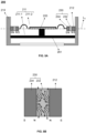
- FIG. 2A is a schematic diagram illustrating a structure of an exemplary speaker according to some embodiments of the present disclosure.
- a speaker 200 is a piezoelectric speaker.
- the speaker 200 includes a shell 210, a diaphragm 220, and a sliding connection portion 230.
- the shell 210 has a cavity 211.
- the diaphragm 220 is accommodated within the cavity 211 and separates the cavity 211 to form at least two sub-cavities (e.g., a first sub-cavity 211-1 and a second sub-cavity 211-2).
- the at least two sub-cavities e.g., the first sub-cavity 211-1 and the second sub-cavity 211-2
- the second sub-cavity 211-2 is communicated with a sound outlet (not shown in the figure) of the shell 210, and the first sub-cavity 211-1 is located on a side of the diaphragm 220 away from the sound outlet.
- the first sub-cavity 211-1 is referred to as a rear cavity and the second sub-cavity 211-2 is referred to as a front cavity.
- the diaphragm 220 is driven by an electrical signal to vibrate relative to the shell 210 to generate sound.
- the sliding connection portion 230 is configured to connect an edge of the diaphragm 220 to an inner wall of the cavity.
- the sliding connection portion 230 is configured to allow the edge of the diaphragm 220 to slide relative to the inner wall of the shell 210, which in turn allows the diaphragm 120 as a whole to slide relative to the inner wall of the shell 110.
- the diaphragm 220 of the speaker 200 is displaced as a whole relative to the shell 210, which generates a greater displacement (e.g., a position of the diaphragm 220 in the dashed line in FIG. 2A relative to the position of the diaphragm 220 in the solid line), thereby increasing a volume of the air pushed by the diaphragm 220, and thereby enhancing the performance of the speaker 200.
- the carrier liquid of the magnetic fluid 232 is an aqueous liquid or an oily liquid.
- the carrier liquid of the magnetic fluid 232 is water, kerosene, motor oil, polyphenylene ether, silicone oil, etc., or any combination thereof.
- the shell 210 includes the first magnet 212.
- the first magnet 212 is disposed in a region on the inner wall of the cavity 211 of the shell 210 corresponding to the position of the diaphragm 220.
- the region on the inner wall of the cavity 211 of the shell 210 corresponding to the position of the diaphragm 220 refers to a region on the inner wall of the cavity 211 of the shell 210 covered by a vibration amplitude of the diaphragm 220, i.e., a sliding range of the magnetic fluid 232.
- the sliding range of the magnetic fluid 232 is in a range of 0mm-5mm.
- a surface of the first magnet 212 forms at least a portion of the inner wall of the cavity of the shell 210.
- a size of the first magnet 212 is greater than the vibration amplitude of the diaphragm 220 along the vibration direction of the diaphragm 220. In other words, the vibration amplitude of the diaphragm 220 (or a movement range of the magnetic fluid 232) does not exceed a size range of the first magnet 212.
- the first magnet 212 includes a permanent magnet or a flexible magnet.
- the first magnet 212 is a magnet.
- the edge of the diaphragm 220 is connected to the magnetic fluid 232.
- the magnetic fluid 232 is disposed between the edge of the diaphragm 220 and the first magnet 212.
- the diaphragm 220 drives the magnetic fluid 232 (i.e., the sliding connection portion 230) to slide on the surface of the first magnet 212.
- the first magnet 212 makes the magnetic fluid 232 to remain in contact with the first magnet 212 at all times during the vibration process of the diaphragm 220, so as to ensure that the first sub-cavity 211-1 and the second sub-cavity 211-2 do not conduct.
- the diaphragm 220 is allowed to achieve a piston movement, which in turn enhances output of the speaker 200, especially the output at low frequencies (as shown in FIG.
- the Q value of the speaker 200 is adjusted to further enhance the performance of the speaker 200. For example, by increasing the viscosity of the carrier liquid of the magnetic fluid 232, the damping of the magnetic fluid 232 is increased, which decreases the Q value of the speaker 200. Correspondingly, by decreasing the viscosity of the carrier liquid of the magnetic fluid 232, the damping of the magnetic fluid 232 is decreased, and thus the Q value of the speaker 200 is increased.
- the Q value of the speaker 200 is reduced.
- the Q value of the speaker 200 is increased.
- the edge of the diaphragm 220 is disposed with a magnetic fluid fixing member (not shown) for connecting the magnetic fluid 232 to the diaphragm 220.
- the magnetic fluid fixing member has a relatively large contact surface with the magnetic fluid 232, so that the magnetic fluid 232 is stably constrained within the magnetic fluid fixing member.
- the magnetic fluid fixing member has a "concave” structure, and the magnetic fluid 232 is placed within the "concave” structure.
- a distance between the edge of the diaphragm 220 and the first magnet 212 is in a range of 20 ⁇ m-2 mm.
- the hydrophilic or lipophilic property of a surface material of the magnetic fluid fixing member consists with the carrier liquid property (also be referred to as the property of the carrier liquid) of the magnetic fluid 232, so as to enhance an intermolecular force (e.g., Van der Waals force) between the surface material of the magnetic fluid fixing member and the carrier liquid of the magnetic fluid 232, allowing the magnetic fluid fixing member to better constrain the magnetic fluid 232.
- the carrier liquid property also be referred to as the property of the carrier liquid
- an intermolecular force e.g., Van der Waals force
- the hydrophilic or lipophilic property of the material consisting the carrier liquid property of the magnetic fluid 232 refers to that if the carrier liquid property of the magnetic fluid 232 is an aqueous liquid, the material is a hydrophilic material, and on the contrary, if the carrier liquid property of the magnetic fluid 232 is an oily liquid, the material is lipophilic material.
- the magnetic fluid 232 adopts any regular or irregular shape (e.g., the magnetic fluid 232 is wrapped by a film with a surface contour). In some embodiments, a specific amount of magnetic fluid 232 is determined according to actual situations. For example, the magnetic fluid 232 is dispersed between the first magnet 212 and the edge of the diaphragm 220 in a controlled manner to limit the amount of magnetic fluid 232.
- the speaker 200 further includes a piezoelectric element 261 and a vibration transfer unit 262.
- the piezoelectric element 261 is fixed to an inner wall of the first sub-cavity 211-1 of the shell 210 and connected to the diaphragm 220 through the vibration transfer unit 262.
- the piezoelectric element 261 powers the vibration of the diaphragm 220.
- the vibration transfer unit 262 transfers the vibration generated by the piezoelectric element 261 to the diaphragm 220, thereby making the diaphragm 220 to vibrate to generate sound.
- the shell 210 is further disposed with a second opening (not shown in the figures) connected to the first sub-cavity 211-1.
- the second opening allows the air to move freely in and out of the first sub-cavity 211-1 to enable changes in an air pressure in the second sub-cavity 211-2 to be as free from stagnation by the first sub-cavity 211-1 as possible, and thereby improving a sound quality of the sound output to the ear via the sound outlet.
- the second opening is disposed with a dustproof/damping mesh 263 to increase the waterproof and dustproof performance of the speaker 200 and adjust a frequency response curve of the speaker 200.
- FIG. 2B is a schematic diagram illustrating a structure of an exemplary speaker according to some other embodiments of the present disclosure. As shown in FIG. 2B , the speaker 200 is an electromagnetic speaker.
- the electromagnetic speaker shown in FIG. 2B and the piezoelectric speaker shown in FIG. 2A have the same or similar structure except for a driving system.
- the electromagnetic speaker shown in FIG. 2B has the shell 210, the diaphragm 220, and the sliding connection portion 230.
- the shell 210 has the cavity 211.
- the diaphragm 220 is accommodated within the cavity 211 and separates the cavity 211 to form at least two sub-cavities (e.g., the first sub-cavity 211-1 and the second sub-cavity 211-2).
- the diaphragm 220 is driven by an electrical signal and vibrates relative to the shell 210 to generate sound.
- the shell 210 includes the first magnet 212, and the sliding connection portion 230 is the magnetic fluid 232.
- the magnetic fluid 232 connects an edge of the diaphragm 220 to an inner wall of the cavity and allows the edge of the diaphragm 220 to slide relative to the inner wall of the shell 210, thereby allowing the diaphragm 220 to generate a greater displacement (e.g., a position of the diaphragm 220 shown by the dashed line in FIG. 2B relative to the position of the diaphragm 220 shown by the solid line), and increasing an amount of air pushed by the diaphragm 220, so as to enhance the performance of the speaker 200.
- a greater displacement e.g., a position of the diaphragm 220 shown by the dashed line in FIG. 2B relative to the position of the diaphragm 220 shown by the solid line
- the speaker 200 also includes a magnetic element 264, a magnetic conductive element 265, and a sound coil 266.
- the magnetic element 264, the magnetic conductive element 265, and the sound coil 266 are all disposed within the first sub-cavity 211-1.
- the magnetic element 264 is configured to provide a magnetic field.
- a magnetic gap is formed between the magnetic element 264 and the magnetic conductive element 265.
- the sound coil 266 is disposed on the diaphragm 220 and located in the magnetic gap. The sound coil 266 is connected to the diaphragm 220.
- the sound coil 266 When a current passes through the sound coil 266, the sound coil 266 is located within the magnetic field formed by the magnetic element 264 and the magnetic conductive element 265, and is subjected to an action of an amperometric force.
- the amperometric force drives the sound coil 266 to vibrate, and the vibration of the sound coil 266 drives the diaphragm 220 to vibrate, thereby generating sound.
- the present disclosure uses a piezoelectric speaker as an example to describe the speaker 200.
- FIG. 3 is a schematic diagram illustrating frequency response curves of a speaker with a sliding connection portion and a speaker without the sliding connection portion according to some embodiments of the present disclosure.
- curve L1 represents a frequency response curve of a speaker (e.g., the speaker 200) with the sliding connection portion.
- Curve L2 represents a frequency response curve of a speaker without the sliding connection portion.
- the speaker with the sliding connection portion (corresponding to curve L1) has a stronger output than the speaker without the sliding connection portion (corresponding to curve L2), and the provision of the sliding connection portion improves the output in the low frequency range (e.g., 200 Hz-1000 Hz) more significantly (e.g., by 20 dB-40 dB for the low frequency range) than the middle frequency range.
- the output performance of the speaker 200 in the low and middle frequency range, especially the low frequency range is improved.
- the diaphragm 220 generates a greater displacement under the same driving force, thereby increasing the amount of air pushed by the diaphragm 220, and improving the performance of the speaker 200.
- FIG. 4 is a schematic diagram illustrating a structure of an exemplary speaker according to some embodiments of the present disclosure.
- the sliding connection portion 230 includes the magnetic fluid 232 and a second magnet 234.
- the first magnet 212 is not provided on the shell 210.
- An inner wall of the cavity 211 is a smooth surface.
- An edge of the diaphragm 220 is connected to the second magnet 234.
- the second magnet 234 is connected to the inner wall of the cavity 211 of the shell 210 through the magnetic fluid 232.
- the magnetic fluid 232 slides with the second magnet 234 relative to the inner wall of the shell 210 through a magnetic force between the magnetic fluid 232 and the second magnet 234, so that the diaphragm 220 generates a greater displacement (e.g., a position of the diaphragm 220 shown by the dashed line relative to the position of the diaphragm 220 shown by the solid line in FIG. 4 ), thereby increasing an amount of air pushed by the diaphragm 220, and improving the performance of the speaker 200.
- a greater displacement e.g., a position of the diaphragm 220 shown by the dashed line relative to the position of the diaphragm 220 shown by the solid line in FIG. 4
- the diaphragm 220 drives the second magnet 234 to move.
- the second magnet 234 drives the magnetic fluid 232 to move with the second magnet 234, so that the magnetic fluid 232 remains in contact with the inner wall of the cavity 211, thereby ensuring that the first sub-cavity 211-1 does not conduct with the second sub-cavity 211-2.
- the diaphragm 220 is able to perform a piston movement, which in turn improves the output of the speaker 200.
- a Q value of the speaker 200 is adjusted, thereby further improving the performance of the speaker 200.
- a distance between the inner wall of the cavity 211 and the second magnet 234 is in a range of 20 ⁇ m-2 mm.
- a surface material of the inner wall of the cavity 211 or the carrier liquid of the magnetic fluid 232 is changed, so as to make the carrier liquid property to be consistent with the hydrophilic or lipophilic property of the surface material of the inner wall of the cavity 211.
- the surface material of the inner wall of the cavity 211 is a hydrophilic material.
- the surface material of the inner wall of the cavity 211 is an oleophilic material. In this way, during the movement of the magnetic fluid 232 along with the second magnet 234, the magnetic fluid 232 is always adhered to the inner wall of the cavity 211, so as to maintain the sealing between the edge of the diaphragm 220 and the inner wall of the shell 210.
- the carrier liquid of the magnetic fluid 232 or the surface material of the inner wall of the cavity 211 is changed, so that the carrier liquid property is consistent with the hydrophilic or lipophilic property of the surface material of the inner wall of the cavity 211 within a sliding range of the magnetic fluid 232, and the carrier liquid property is inconsistent with the hydrophilic or lipophilic property of the surface material of the inner wall of the cavity 211 outside the sliding range of the magnetic fluid 232.
- the carrier liquid of the magnetic fluid 232 is an aqueous liquid or an oily liquid.
- the material of the inner wall of the cavity 211 within the sliding range of the magnetic fluid 232 is a first surface material.
- the material of the inner wall of the cavity 211 outside the sliding range of the magnetic fluid 232 is a second surface material.
- the carrier liquid property of the magnetic fluid 232 is the same as the hydrophilic or lipophilic property of the first surface material, and the hydrophilic or lipophilic property of the first surface material is opposite to the hydrophilic or lipophilic property of the second surface material.
- the difference between the hydrophilic-lipophilic balance value of the first surface material and the hydrophilic-lipophilic balance value of the second surface material is in a range of 2-40.
- the difference between the hydrophilic-lipophilic balance value of the first surface material and the hydrophilic-lipophilic balance value of the second surface material is in a range of 5-40. More preferably, the difference between the hydrophilic-lipophilic balance value of the first surface material and the hydrophilic-lipophilic balance value of the second surface material is in a range of 9-40.
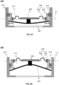
- FIG. 5A is a schematic diagram illustrating a structure of an exemplary speaker according to some embodiments of the present disclosure.
- FIG. 5B is a schematic illustrating a local distribution of magnetic induction lines of a magnet in FIG. 5A .
- FIG. 5C is a schematic diagram illustrating the speaker shown in FIG. 5A when the diaphragm is in a position with a first maximum vibration amplitude.
- FIG. 5D is a schematic diagram illustrating the speaker shown in FIG. 5A when the diaphragm is in a position with a second maximum vibration amplitude.
- the first magnet 212 and the second magnet 234 are arranged with the same magnetic poles facing each other.
- an S magnetic pole of the first magnet 212 and an S magnetic pole of the second magnet 234 faces each other (i.e., the S magnetic poles of the first magnet 212 and the second magnet 234 are disposed adjacent to each other); or, an N magnetic pole of the first magnet 212 and an N magnetic pole of the second magnet 234 faces each other (i.e., the N magnetic poles of the first magnet 212 and the second magnet 234 are disposed adjacent to each other).
- the first magnet 212 and the second magnet 234 are made to repel each other, thereby making a state when the first magnet 212 and the second magnet 234 face to each other (as shown in FIG. 5A , the diaphragm 220 is located at a position of an initial structural balance line L0) is a non-balance state.
- the diaphragm 220 In the vibration direction of the diaphragm 220, when the diaphragm 220 reaches downwardly to a position of a first maximum vibration amplitude, the diaphragm 220 is in a first balance state (e.g., as shown in FIG.
- the speaker 200 in a process of switching, due to the presence of a magnet repelling force, the speaker 200 reaches another balance state quickly under an action of the magnetic force with a very small driving force after passing the position of the initial structural balance line L0, and thus improve a diaphragm travel of the speaker 200 and a vibration speed of the diaphragm 220, thereby improving the output performance of the speaker 200.
- a height of the first magnet 212 is set relatively small, e.g., the height of the first magnet 212 is the same as a height of the second magnet 234 and a height of the magnetic fluid 232, as shown in FIG. 5A and FIG. 5B .
- the first magnet 212 is set at a position on the shell 210 corresponding to the initial structural balance line L0 (i.e., an initial position of the diaphragm 220).
- the height of the first magnet 212 is smaller than the vibration amplitude of the diaphragm 220.
- the magnetic fluid 232 is subjected to the magnetic force of the second magnet 234 and the first magnet 212, and the extended portion of the magnetic fluid 232 is retracted to the range of the corresponding region of the surface of the first magnet 212.
- the height of the first magnet 212 is set relatively great along the vibration direction of the diaphragm 220, e.g., the height of the first magnet 212 is set to match the vibration amplitude of the diaphragm 220.
- a position relationship between the first magnet 212 and the magnetic fluid 232 is similar to the relationship shown in FIG. 2A .
- the second magnet 234 follows the diaphragm 220 to move and drives the magnetic fluid 232 to slide on the surface of the first magnet 212.
- the magnetic fluid 232 (e.g., as the magnetic fluid 232 in the speaker 200 shown in FIG. 2A , FIG.4 , and FIG. 5A ) vibrates up and down with the vibration of the diaphragm 220.
- the magnetic attraction of the magnet e.g., the first magnet 212 and/or the second magnet 234
- the magnetic fluid 232 is not sufficient to fully constrain the magnetic fluid 232, resulting in the magnetic fluid 232 to splash.
- the splash of the magnetic fluid 232 causes a total amount of the magnetic fluid 232 to become less and less, which ultimately affects the stable output of the speaker 200
- the splash of the magnetic fluid 232 causes an interference for other components of the speaker 200.
- the speaker 200 further includes a magnetic fluid constraint structure.
- the magnetic fluid constraint structure constrains the magnetic fluid 232, and limits a position range of the magnetic fluid 232, thereby better avoiding the splash of the magnetic fluid 232.
- the magnetic fluid constraint structure 240 when there is no second magnet 234 between the magnetic fluid 232 and the diaphragm 220 (as shown in FIG. 2A ), the magnetic fluid constraint structure 240 is disposed at a position where the magnetic fluid 232 is connected to the diaphragm 220. At this time, the magnetic fluid constraint structure 240 is equivalent to the aforementioned magnetic fluid fixing member. At this time, the magnetic fluid constraint structure 240, on the one hand, constrains the magnetic fluid 232 to avoid the splashing at the position where the magnetic fluid 232 is connected to the diaphragm 220, and on the other hand, increases the connection strength of between the magnetic fluid 232 and the diaphragm 220.
- the magnetic fluid constraint structure 240 is disposed on the second magnet 234.
- first magnetic fluid constraint element 241 and the second magnetic fluid constraint element 242 are annular, so as to facilitate constraining all directions of the magnetic fluid 232, which is distributed in an annular shape between the diaphragm 220 and the inner wall of the shell 210.
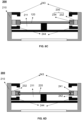
- FIG. 6B is a schematic diagram illustrating a structure of an exemplary speaker according to some other embodiments of the present disclosure.
- the magnetic fluid constraint structure 240 also includes a third magnetic fluid constraint element 243 and a fourth magnetic fluid constraint element 244.
- the third magnetic fluid constraint element 243 and the fourth magnetic fluid constraint element 244 are disposed on the shell 210.
- the third magnetic fluid constraint element 243 and the fourth magnetic fluid constraint element 244 are respectively disposed on the inner wall of the cavity 211 and are located outside the sliding range of the magnetic fluid 232.
- the first magnetic fluid constraint element 241 and the second magnetic fluid constraint element 242 are disposed at the edge of the diaphragm 220, thereby constraining the magnetic fluid 232 near the first magnetic fluid constraint element 241 and the second magnetic fluid constraint element 242, i.e., between the edge of the diaphragm 220 and the inner wall of the shell 210, thereby allowing the magnetic fluid 232 to slide with the first magnetic fluid constraint element 241 and the second magnetic fluid constraint element 242 relative to the inner wall of the shell 210.
- a carrier liquid property of the magnetic fluid 232 is set to be the same as the hydrophilic or lipophilic property of the magnetic fluid constraint structure 240 (i.e., the first magnetic fluid constraint element 241 and/or the second magnetic fluid constraint element 242) to increase an adsorption force of the magnetic fluid constraint structure 240 on the magnetic fluid 232.
- the carrier liquid property of the magnetic fluid 232 is set to be opposite to the hydrophilic or lipophilic property of the magnetic fluid constraint structure 240 (i.e., the third magnetic fluid constraint element 243 and/or the or the fourth magnetic fluid constraint element 244), thereby making the magnetic fluid 232 to repel the third magnetic fluid constraint element 243 and/or the fourth magnetic fluid constraint element 244, and reducing an adsorption capacity of the magnetic fluid constraint structure 240 (i.e., the third magnetic fluid constraint element 243 and/or the fourth magnetic fluid constraint element 244) disposed on the shell 210 on the magnetic fluid 232.
- the fourth surface material of the magnetic fluid constraint structure 240 i.e., the third magnetic fluid constraint element 243 and the fourth magnetic fluid constraint element 244 disposed on the shell 210 is a hydrophilic material to reduce an adhesion force of the fourth surface material of the magnetic fluid constraint structure 240 (i.e., the third magnetic fluid constraint element 243 and the fourth magnetic fluid constraint element 244) disposed on the shell 210 to the magnetic fluid 232, making the magnetic fluid 232 to quickly return to the magnet by the magnetic attraction force of the magnet (e.g., the first magnet 212 and/or the second magnet 234) after the magnetic fluid 232 is splashed onto the magnetic fluid constraint structure 240 (i.e., the third magnetic fluid constraint element 243 and/or the fourth magnetic fluid constraint element 244) disposed on the shell 210.
- the difference between the hydrophilic-lipophilic balance value of the fourth surface material of the magnetic fluid constraint structure 240 disposed on the shell 210 and the hydrophilic-lipophilic balance value of the carrier liquid of the magnetic fluid 232 is in a range of 2-40.
- FIG. 6C is a schematic diagram illustrating a structure of an exemplary speaker according to other embodiments of the present disclosure.
- the magnetic fluid constraint structure 240 i.e., the third magnetic fluid constraint element 243 and the fourth magnetic fluid constraint element 244 disposed on the shell 210 is a constraint structure with a folded edge. The folded edge faces the diaphragm 220. By disposing the folded edge, the magnetic fluid constraint structure 240 disposed on the shell 210 is able to further constrain the magnetic fluid 232 in an extension direction of the diaphragm 220. Exemplarily, with reference to FIG.
- FIG. 6D is a schematic diagram illustrating a structure of an exemplary speaker according to some other embodiments of the present disclosure.
- the magnetic fluid constraint structure 240 includes both the first magnetic fluid constraint element 241 and the second magnetic fluid constraint element 242 disposed on the diaphragm 220 and the third magnetic fluid constraint element 243 and the fourth magnetic fluid constraint element 244 disposed on the shell 210.
- the first magnetic fluid constraint element 241 and the second magnetic fluid constraint element 242 may be annular structures, and the first magnetic fluid constraint element 241 and the second magnetic fluid constraint element 242 are disposed at a connection position between the magnetic fluid 232 and the diaphragm 220.
- the speaker 200 does not include a magnet (e.g., the first magnet 212 and/or the second magnet 234), at which point the sliding connection portion 230 is a fluid 236.
- the diaphragm 220 is connected to the shell 210 through the fluid 236.
- the fluid 236 deforms to adapt to the vibration of the diaphragm 220 (as shown in FIG. 7B ).
- the fluid 236 keeps the first sub-cavity 211-1 and the second sub-cavity 211-2 from conducting.
- the diaphragm 220 achieves the piston movement, which in turn improves the output of the speaker 200. Further, by changing the property of the fluid 236, the Q value of the speaker 200 can be adjusted, thereby further enhancing the performance of the speaker 200.
- the fluid 236 is connected to the diaphragm 220 through a fluid fixing member (not shown), so that the diaphragm 220 drives the fluid 236 to deform.
- the fluid fixing member is similar to the magnetic fluid fixing member.
- the fluid fixing member has a great contact surface with the fluid 236, such that the fluid 236 is stably constrained within the fluid fixing member.
- the fluid fixing member has a "concave” structure, and the fluid 236 is constrained within the "concave” structure.
- the hydrophilic or lipophilic property of the surface material of the fluid fixing member is consistent with the hydrophilic or lipophilic property of the fluid 236 to improve the intermolecular force (e.g., Van der Waals force) between the surface material of the fluid fixing member and the fluid 236, so that the fluid fixing member can better constrain the fluid 236.
- intermolecular force e.g., Van der Waals force
- the property of the fluid 236 is consistent with the hydrophilic or lipophilic property of the surface material of the inner wall of the cavity 211 inside the sliding range of the fluid 236, and the property of the fluid 236 is opposite to the hydrophilic or lipophilic property of the surface material of the inner wall of the cavity 211 outside the sliding range of the fluid 236.
- the fluid 236 may be an aqueous liquid or oily liquid.
- the material of the inner wall of the cavity 211 within the sliding range of the fluid 236 is a first surface material.
- the material of the inner wall of the cavity 211 outside the sliding range of the fluid 236 is a second surface material.
- the fluid 236 has the same hydrophilic or lipophilic property as the first surface material, and the hydrophilic or lipophilic properties of the first surface material and the second surface material are opposite.
- the fluid 236 is a viscous fluid.
- the diaphragm 220 is driven to deform the viscous fluid by a viscous force of the viscous fluid.
- a kinematic viscosity of the viscous fluid is greater than 100 cst.
- the viscous fluid includes, but is not limited to, materials such as gels, sealants, oils, etc.
- the inner wall of the cavity 211 is disposed with a concave or convex structure 213 in a region in contact with the fluid 236.
- the concave or convex structure 213 effectively improves an absorption force of the fluid 236 by the inner wall of the shell 210.
- the concave or convex structure 213 is arranged in a circumferential distribution of the cavity 211 on the inner wall of the shell 210. In some embodiments, the concave or convex structure 213 is disposed on the inner wall of the shell 210. In some embodiments, the concave or convex structure 213 protrudes from the inner wall of the shell 210.
- a shape of the concave or convex structure 213 includes, but is not limited to, a regular or irregular shape such as a columnar structure (as shown in FIG. 8A ), a conical structure (as shown in FIG. 8B ), etc.
- a size of the concave or convex structure 213 on the surface of the inner wall of the cavity 211 is in a range of 0.2 ⁇ m-200 ⁇ m along the vibration direction of the diaphragm 220 (e.g., such as direction Z in FIG. 8A ), and is in a range of 0.2 ⁇ m-200 ⁇ m in a direction perpendicular to the inner wall of the cavity 211 (e.g., such as direction X in FIG. 8A ).
- each convex structure e.g., a columnar structure
- each convex structure has a size in a range of 1 ⁇ m-100 ⁇ m along the vibration direction of the diaphragm 220, and a size in a range of 1 ⁇ m-100 ⁇ m along the direction perpendicular to the inner wall of the cavity 211.
- each concave structure e.g., the columnar structure
- FIG. 9A is a schematic diagram illustrating a structure of an exemplary speaker according to some embodiments of the present disclosure.
- FIG. 9B is a schematic diagram illustrating a structure of an exemplary speaker according to some other embodiments of the present disclosure.
- the speaker 200 when the sliding connection portion 230 is the fluid 236 (e.g., a viscous fluid), the speaker 200 also includes a fluid constraint structure 250.
- the fluid constraint structure 250 further constrains the fluid 236, limiting a movement range of the fluid 236, thereby better avoiding a disengagement of the fluid 236 from the inner wall of the shell 210.
- the fluid constraint structure 250 includes an annular structure, as shown in FIG. 9A .
- the annular structure of the fluid constraint structure 250 further includes a folded edge. The folded edge is disposed along a direction facing the diaphragm 220, as shown in FIG. 9B .
- the relevant settings of the fluid 236 and the fluid constraint structure 250 are referred to the settings of the magnetic fluid 232 and the magnetic fluid constraint structure 240 in FIG. 6B , FIG. 6C , which are not repeated here.
- Beneficial effects of the speaker include, but are not limited to: (1) by disposing the sliding connection portion, the diaphragm as a whole slides relative to the shell, thereby increasing the volume of air pushed by the diaphragm, and improving the performance of the speaker; (2) by designing the magnetic fluid to cooperate with the first magnet and/or the second magnet, while ensuring that the first sub-cavity is not conduct to the second sub-cavity, a flexible control of the movement of the magnetic fluid is achieved, thereby enabling the diaphragm to realize a good piston movement; (3) by disposing the same magnetic poles of the first magnet and the second magnet face to each other, the moving displacement of the diaphragm is increased, thereby improving the travel and the vibration speed of the diaphragm, and improving the output performance of the speaker; (4) by disposing a corresponding constraint structure for the magnetic fluid or the fluid to constrain the magnetic fluid or the fluid, thereby better avoiding the magnetic fluid or the fluid from falling off; (5) by disposing a corresponding constraint structure
Landscapes
- Engineering & Computer Science (AREA)
- Physics & Mathematics (AREA)
- Acoustics & Sound (AREA)
- Signal Processing (AREA)
- Multimedia (AREA)
- Audible-Bandwidth Dynamoelectric Transducers Other Than Pickups (AREA)
Abstract
Description
- The present disclosure relates to the field of acoustic technology, and in particular, to a speaker.
- In a structure of an existing speaker, to avoid the front and rear cavities of the speaker from conducting, which affects a radiated sound pressure of the speaker, an edge of a diaphragm of the speaker is usually fixedly connected to a shell of the speaker. With such a structure, when the speaker is operating, the deformation of the diaphragm mainly occurs in a center region, while the deformation in a region near the fixed edge of the diaphragm is smaller. The deformation of the center region of the diaphragm is also limited by the region where the fixed edge is located, thus reducing a volume of air pushed by the diaphragm (also known as an air push volume), which has a negative impact on the performance of the speaker, in particular, impacts the low frequency performance of the speaker requiring a great displacement and a great air push volume.
- Therefore, it is necessary to propose a speaker to increase the volume of air pushed by the diaphragm and enhance the low frequency performance of the speaker.
- One of the embodiments of the present disclosure provides a speaker including a shell including a cavity, a diaphragm accommodated within the cavity, and a sliding connection portion. The diaphragm separates the cavity to form at least two sub-cavities. The diaphragm is driven by an electrical signal to vibrate with respect to the shell to generate sound. The sliding connection portion is configured to connect an edge of the diaphragm to an inner wall of the cavity, the sliding connection portion allowing the edge of the diaphragm to slide relative to an inner wall of the shell.
- In some embodiments, the shell includes a magnet, the sliding connection portion is a magnetic fluid, a surface of the magnet forms at least a portion of the inner wall of the cavity, and the diaphragm drives the magnetic fluid to slide on the surface of the magnet.
- In some embodiments, the sliding connection section includes a magnet and a magnetic fluid. The magnet is connected to the diaphragm, and the magnetic fluid is configured to connect the magnet to the inner wall of the cavity. The magnetic fluid slides with the magnet relative to the inner wall of the shell by a magnetic force between the magnetic fluid and the magnet.
- In some embodiments, a carrier liquid of the magnetic fluid is an aqueous liquid or an oily liquid, a material of the inner wall of the cavity within a sliding range of the magnetic fluid is a first surface material, and a material of the inner wall of the cavity outside the sliding range of the magnetic fluid is a second surface material. A property of the carrier liquid is the same as a hydrophilic or lipophilic property of the first surface material, and the first surface material and the second surface material have opposite hydrophilic or lipophilic properties.
- In some embodiments, the shell includes a first magnet, and the sliding connection portion includes a second magnet and a magnetic fluid. A surface of the first magnet forms at least a portion of the inner wall of the cavity, the second magnet is connected to the diaphragm, and the magnetic fluid is configured to connect the first magnet to the second magnet, and the diaphragm drives, through the second magnet, the magnetic fluid to slide on the surface of the first magnet.
- In some embodiments, the first magnet and the second magnet are arranged with the same magnetic poles facing each other.
- In some embodiments, the speaker further includes a magnetic fluid constraint structure configured to constrain a position of the magnetic fluid.
- In some embodiments, the magnetic fluid constraint structure includes a first magnetic fluid constraint element and a second magnetic fluid restraint element that are disposed on the diaphragm, the first magnetic fluid restraint element and the second magnetic fluid constraint element being provided to be located on opposite sides of the magnetic fluid along a vibration direction of the diaphragm, respectively.
- In some embodiments, the first magnetic fluid constraint element and the second magnetic fluid restraint element are disposed on the inner wall of the cavity and located outside the sliding range of the magnetic fluid. A distance between the first magnetic fluid constraint element and an edge of the sliding range is within a first distance threshold range, and a distance between the second magnetic fluid constraint element and the edge of the sliding range is within a second distance threshold range.
- In some embodiments, the property of the carrier liquid of the magnetic fluid is the same as or opposite to the hydrophilic or lipophilic property of the surface material of the magnetic fluid constraint structure.
- In some embodiments, the sliding connection portion is a fluid, wherein the material of the inner wall of the cavity within the sliding range of the fluid is a first surface material, and the material of the inner wall of the cavity outside the sliding range of the fluid is a second surface material, wherein the fluid has the same hydrophilic or lipophilic property as the first surface material, and the first surface material has opposite hydrophilic or lipophilic property as the second surface material.
- In some embodiments, the fluid is a viscous fluid with a kinematic viscosity greater than 100 cst.
- In some embodiments, the cavity is disposed with a concave or convex structure within a region on the inner wall of the cavity contacting the fluid.
- In some embodiments, a size of the concave or convex structure on a surface of the inner wall of the cavity along a vibration direction of the diaphragm is in a range of 0.2 µm-200 µm, and a size of the concave or convex structure along a direction perpendicular to the inner wall of the cavity is in a range of 0.2 µm-200 µm.
- In some embodiments, the diaphragm is a flat plate structure.
- The present disclosure will be further illustrated by way of exemplary embodiments, which are described in detail by means of the accompanying drawings. These embodiments are not limiting, and in these embodiments, the same numbering indicates the same structure, wherein
-
FIG. 1 is a block diagram illustrating a structure of an exemplary speaker according to some embodiments of the present disclosure; -
FIG. 2A is a schematic diagram illustrating a structure of an exemplary speaker according to some embodiments of the present disclosure; -
FIG. 2B is a schematic diagram illustrating a structure of an exemplary speaker according to some other embodiments of the present disclosure; -
FIG. 3 is a schematic diagram illustrating frequency response curves of a speaker with a sliding connection portion and a speaker without the sliding connection portion according to some embodiments of the present disclosure; -
FIG. 4 is a schematic diagram illustrating a structure of an exemplary speaker according to some embodiments of the present disclosure; -
FIG. 5A is a schematic diagram illustrating a structure of an exemplary speaker according to some embodiments of the present disclosure; -
FIG. 5B is a schematic diagram illustrating a local distribution of magnetic induction lines of a magnet inFIG. 5A ; -
FIG. 5C is a schematic diagram illustrating the speaker shown inFIG. 5A when the diaphragm is in a position with a first maximum vibration amplitude; -
FIG. 5D is a schematic diagram illustrating the speaker shown inFIG. 5A when the diaphragm is in a position with a second maximum vibration amplitude; -
FIG. 6A is a schematic diagram illustrating a structure of an exemplary speaker according to some embodiments of the present disclosure; -
FIG. 6B is a schematic diagram illustrating a structure of an exemplary speaker according to some other embodiments of the present disclosure; -
FIG. 6C is a schematic diagram illustrating a structure of an exemplary speaker according to other embodiments of the present disclosure; -
FIG. 6D is a schematic diagram illustrating a structure of an exemplary speaker according to some other embodiments of the present disclosure; -
FIG. 7A is a schematic diagram illustrating a structure of an exemplary speaker according to some embodiments of the present disclosure; -
FIG. 7B is a schematic diagram illustrating the speaker shown inFIG. 7A when a diaphragm is vibrating; -
FIG. 8A is a schematic diagram illustrating a structure of an exemplary speaker according to some embodiments of the present disclosure; -
FIG. 8B is a schematic diagram illustrating a structure of an exemplary speaker according to some other embodiments of the present disclosure; -
FIG. 9A is a schematic diagram illustrating a structure of an exemplary speaker according to some embodiments of the present disclosure; and -
FIG. 9B is a schematic diagram illustrating a structure of an exemplary speaker according to some other embodiments of the present disclosure. - To more clearly illustrate the technical solutions of the embodiments of the present disclosure, the accompanying drawings required to be used in the description of the embodiments are briefly described below. Obviously, the accompanying drawings in the following description are only some examples or embodiments of the present disclosure, and it is possible for those skilled in the art to apply the present disclosure to other similar scenarios in accordance with these drawings without creative labor. Unless obviously obtained from the context or the context illustrates otherwise, the same numeral in the drawings refers to the same structure or operation.
- It should be understood that as used herein, the terms "system," "device," "unit" and/or "module" as used herein is a way to distinguish between different components, elements, parts, sections, or assemblies at different levels. However, the words are replaced by other expressions if other words accomplish the same purpose.
- As shown in the present disclosure and the claims, unless the context clearly suggests an exception, the words "a," "an," "one," and/or "the" do not refer specifically to the singular, but also include the plural. Generally, the terms "including" and "comprising" suggest only the inclusion of clearly identified operations and elements. In general, the terms "including" and "comprising" only suggest the inclusion of explicitly identified operations and elements that do not constitute an exclusive list, and the method or apparatus also includes other operations or elements.
- In the description of the present disclosure, it is to be understood that the terms "first," "second," "third," "fourth," etc., are used for descriptive purposes only, and are not to be understood as indicating or implying relative importance or implicitly specifying the number of technical features indicated. Thereby, the limitations "first," "second," "third," and "fourth" expressly or implicitly include at least one such feature. In the description of the present disclosure, "plurality" means at least two, e.g., two, three, etc., unless otherwise expressly and specifically limited.
- In the present disclosure, unless otherwise expressly specified or limited, the terms "connection," "fixing," etc. shall be broadly construed. For example, the term "connection" refers to a fixed connection, a removable connection, or an integrated connection; a mechanical connection, or an electrical connection; a direct connection, or an indirect connection through an intermediate medium, a connection within two elements, or an interaction between two elements, unless expressly limited otherwise. To those skilled in the art, the specific meaning of the above terms in the present disclosure is understood on a case-by-case basis.
- The present disclosure provides a speaker including a shell, a diaphragm, and a sliding connection portion. The shell includes a cavity. The diaphragm is accommodated within the cavity, which separates the cavity to form at least two sub-cavities. The diaphragm is driven by an electrical signal to vibrate relative to the shell to generate sound. The sliding connection portion is configured to connect an edge of the diaphragm to an inner wall of the cavity. The sliding connection portion allows the edge of the diaphragm to slide relative to the inner wall of the shell, so that the diaphragm as a whole is able to displace relative to the inner wall of the shell. In other words, the diaphragm as a whole makes a piston-like movement relative to the inner wall of the shell, which allows the diaphragm to generate a greater displacement, push more air, and thereby improving the performance of the speaker, especially the sensitivity of the speaker at a low frequency range.
-
FIG. 1 is a block diagram illustrating a structure of an exemplary speaker according to some embodiments of the present disclosure. In some embodiments, aspeaker 100 includes a piezoelectric speaker (as shown inFIG. 2A ), an electromagnetic speaker (as shown inFIG. 2B ), a moving iron speaker, an electrostatic speaker, etc., or any combination thereof. As shown inFIG. 1 , thespeaker 100 includes ashell 110, adiaphragm 120, and a slidingconnection portion 130. - The
shell 110 is configured to carry other components of the speaker 100 (e.g., thediaphragm 120, the slidingconnection portion 130, etc.). Theshell 110 has a cavity. One or more components of thespeaker 100 are disposed within the cavity. In some embodiments, theshell 110 is a regular or irregular three-dimensional (3D) structure such as a cuboid, a cylinder, etc. When the user wears thespeaker 100, theshell 110 is located near a user's ear. For example, theshell 110 is located on a circumferential side (e.g., a front side or a rear side) of the user's ear. For another example, theshell 110 is disposed over the user's ear without blocking or covering the user's ear canal. For another example, theshell 110 is partially disposed within the user's ear canal. In some embodiments, at least one sound outlet is included in theshell 110, and a sound generated by vibration of thediaphragm 120 is radiated in a direction to the user's ear through the sound outlet. - The
diaphragm 120 is disposed within the cavity of theshell 110 and separates the cavity to form at least two sub-cavities (e.g., a first sub-cavity 211-1 and a second sub-cavity 211-2 as shown inFIG. 2A ). Thediaphragm 120 is driven by an electrical signal to vibrate relative to theshell 110 to generate sound. The at least two sub-cavities are disposed on each side of the vibration direction of thediaphragm 120. - In some embodiments, to facilitate the adjustment of a compliance of the
diaphragm 120 and a Q value of thespeaker 100, a material for preparing thediaphragm 120 is a polymeric non-metallic material, for example, a polyetheretherketone (poly (ether-ether-ether-ketone), PEEK), a polyimide (PI), a polyphenylene sulfide ( polyphenylene sulfide (PPS), poly (ethylene imine) (PEI), a silica gel, etc. In this situation, thespeaker 100 is prone to generate a diaphragm splitting vibration in a middle high frequency band to form one or more higher order modes, which in turn causes more peaks and valleys in the middle high frequency band of a frequency response of thespeaker 100, and affects the performance of thespeaker 100 in the middle high frequency band. - In some embodiments, to reduce the high order mode in the vibration of the
diaphragm 120 so as to enhance the performance of thespeaker 100 in the middle high frequency band, thediaphragm 120 is a rigid vibration component. Specifically, an elastic modulus of the material of thediaphragm 120 is greater than 2E6Pa. Preferably, the elastic modulus of the material of thediaphragm 120 is greater than 4E6Pa. For example, the elastic modulus of the material of thediaphragm 120 is 8E6Pa. In some embodiments, the material of thediaphragm 120 includes a metallic material and a non-metallic material. The metallic material includes, but is not limited to, aluminum alloys, stainless steel, magnesium-lithium alloys, etc. The non-metallic material includes, but is not limited to, carbon fiber composites, plant fiber composites, etc. In some embodiments, the material of thediaphragm 120 is preferably the metallic material with a low density and a high stiffness to make an overall weight of thespeaker 100 smaller and to enhance the wearing experience of the user. - In some embodiments, to reduce a machining difficulty of the
diaphragm 120, thediaphragm 120 is a flat plate structure. For example, thediaphragm 120 is a rigid vibration plate (such as thediaphragm 220 shown inFIG. 6A ). When there is the slidingconnection portion 130, the rigid vibration plate slides in thespeaker 100 relative to theshell 110 such that thediaphragm 120 does not form the splitting vibration in an audible sound range of a human ear (e.g., 20 Hz-20 kHz), thereby flattening the frequency response curve output by thespeaker 100 in the audible sound range of the human ear. - The sliding
connection portion 130 is configured to connect an edge of thediaphragm 120 to an inner wall of the cavity. The slidingconnection portion 130 is configured to allow the edge of thediaphragm 120 to slide relative to the inner wall of theshell 110, which in turn allows thediaphragm 120 as a whole to slide relative to the inner wall of theshell 110. In other words, thediaphragm 120 as a whole performs a piston-like movement relative to theshell 110. In some embodiments, the slidingconnection portion 130 includes a magnetic fluid. At this point, theshell 110 includes a magnet. Thediaphragm 120 drives the magnetic fluid to slide on a surface of the magnet. In some embodiments, the slidingconnection portion 130 includes the magnetic fluid with the magnet. Thediaphragm 120 is connected to the magnetic fluid through the magnet, which is in contact with theshell 110, and thediaphragm 120 drives the magnetic fluid through the magnet to slide on a surface of the inner wall of theshell 110. In some embodiments, theshell 110 includes a first magnet, and the slidingconnection portion 130 includes a magnetic fluid and a second magnet. Thediaphragm 120 is connected to the magnetic fluid through the second magnet. Thediaphragm 120 drives, through the second magnet, the magnetic fluid to slide on a surface of the first magnet. In some embodiments, the slidingconnection portion 130 includes a fluid (e.g., a viscous fluid), and thediaphragm 120 drives the fluid to slide on the surface of the inner wall of theshell 110. More descriptions of the slidingconnection portion 130 may be found elsewhere in the present disclosure, for example,FIGs. 2A-2B ,FIG. 4 ,FIGs. 5A-5D ,FIGs. 7A-7B ,FIGs. 8A-8B , etc., and their descriptions. -
FIG. 2A is a schematic diagram illustrating a structure of an exemplary speaker according to some embodiments of the present disclosure. As shown inFIG. 2A , aspeaker 200 is a piezoelectric speaker. Thespeaker 200 includes ashell 210, adiaphragm 220, and a slidingconnection portion 230. - The
shell 210 has acavity 211. Thediaphragm 220 is accommodated within thecavity 211 and separates thecavity 211 to form at least two sub-cavities (e.g., a first sub-cavity 211-1 and a second sub-cavity 211-2). The at least two sub-cavities (e.g., the first sub-cavity 211-1 and the second sub-cavity 211-2) are disposed on each side of a vibration direction of thediaphragm 220. The second sub-cavity 211-2 is communicated with a sound outlet (not shown in the figure) of theshell 210, and the first sub-cavity 211-1 is located on a side of thediaphragm 220 away from the sound outlet. In some embodiments, the first sub-cavity 211-1 is referred to as a rear cavity and the second sub-cavity 211-2 is referred to as a front cavity. Thediaphragm 220 is driven by an electrical signal to vibrate relative to theshell 210 to generate sound. - The sliding
connection portion 230 is configured to connect an edge of thediaphragm 220 to an inner wall of the cavity. The slidingconnection portion 230 is configured to allow the edge of thediaphragm 220 to slide relative to the inner wall of theshell 210, which in turn allows thediaphragm 120 as a whole to slide relative to the inner wall of theshell 110. Thus, relative to a speaker where the edge of the diaphragm does not slide relative to the inner wall of the shell, thediaphragm 220 of thespeaker 200 is displaced as a whole relative to theshell 210, which generates a greater displacement (e.g., a position of thediaphragm 220 in the dashed line inFIG. 2A relative to the position of thediaphragm 220 in the solid line), thereby increasing a volume of the air pushed by thediaphragm 220, and thereby enhancing the performance of thespeaker 200. - In some embodiments, the sliding
connection portion 230 is amagnetic fluid 232, as shown inFIG. 2A . In some embodiments, themagnetic fluid 232 includes a liquid (e.g., a colloidal liquid) made of magnetic particles (e.g., nanoscale ferromagnetic or subferromagnetic particles, iron nitride particles, etc.) suspended in a carrier liquid. Themagnetic fluid 232 responds to an external magnetic field (e.g., a magnetic field of thefirst magnet 212 as described later), i.e., themagnetic fluid 232 is attracted to a nearby magnet (e.g., thefirst magnet 212 as described later, etc.). In some embodiments, the carrier liquid of themagnetic fluid 232 is an aqueous liquid or an oily liquid. For example, the carrier liquid of themagnetic fluid 232 is water, kerosene, motor oil, polyphenylene ether, silicone oil, etc., or any combination thereof. - When the sliding
connection portion 230 is themagnetic fluid 232, theshell 210 includes thefirst magnet 212. Thefirst magnet 212 is disposed in a region on the inner wall of thecavity 211 of theshell 210 corresponding to the position of thediaphragm 220. In some embodiments, the region on the inner wall of thecavity 211 of theshell 210 corresponding to the position of thediaphragm 220 refers to a region on the inner wall of thecavity 211 of theshell 210 covered by a vibration amplitude of thediaphragm 220, i.e., a sliding range of themagnetic fluid 232. In some embodiments, the sliding range of themagnetic fluid 232 is in a range of 0mm-5mm. A surface of thefirst magnet 212 forms at least a portion of the inner wall of the cavity of theshell 210. In some embodiments, a size of thefirst magnet 212 is greater than the vibration amplitude of thediaphragm 220 along the vibration direction of thediaphragm 220. In other words, the vibration amplitude of the diaphragm 220 (or a movement range of the magnetic fluid 232) does not exceed a size range of thefirst magnet 212. In some embodiments, thefirst magnet 212 includes a permanent magnet or a flexible magnet. For example, thefirst magnet 212 is a magnet. - The edge of the
diaphragm 220 is connected to themagnetic fluid 232. Themagnetic fluid 232 is disposed between the edge of thediaphragm 220 and thefirst magnet 212. Thediaphragm 220 drives the magnetic fluid 232 (i.e., the sliding connection portion 230) to slide on the surface of thefirst magnet 212. During a vibration process of the diaphragm 220 (or a sliding process of thediaphragm 220 relative to the shell 210), due to the existence of a magnetic attraction between thefirst magnet 212 and themagnetic fluid 232, thefirst magnet 212 makes themagnetic fluid 232 to remain in contact with thefirst magnet 212 at all times during the vibration process of thediaphragm 220, so as to ensure that the first sub-cavity 211-1 and the second sub-cavity 211-2 do not conduct. At the same time, as thefirst magnet 212 has less constraint on thediaphragm 220, thediaphragm 220 is allowed to achieve a piston movement, which in turn enhances output of thespeaker 200, especially the output at low frequencies (as shown inFIG. 3 ). In some embodiments, by changing the carrier liquid of themagnetic fluid 232, the Q value of thespeaker 200 is adjusted to further enhance the performance of thespeaker 200. For example, by increasing the viscosity of the carrier liquid of themagnetic fluid 232, the damping of themagnetic fluid 232 is increased, which decreases the Q value of thespeaker 200. Correspondingly, by decreasing the viscosity of the carrier liquid of themagnetic fluid 232, the damping of themagnetic fluid 232 is decreased, and thus the Q value of thespeaker 200 is increased. For another example, by reducing a width of a gap where themagnetic fluid 232 is located (i.e., a distance between thediaphragm 220 and the inner wall of thecavity 211 of the shell 210), the Q value of thespeaker 200 is reduced. Correspondingly, by increasing the width of the gap where themagnetic fluid 232 is located, the Q value of thespeaker 200 is increased. - In some embodiments, the edge of the
diaphragm 220 is disposed with a magnetic fluid fixing member (not shown) for connecting themagnetic fluid 232 to thediaphragm 220. The magnetic fluid fixing member has a relatively large contact surface with themagnetic fluid 232, so that themagnetic fluid 232 is stably constrained within the magnetic fluid fixing member. For example, the magnetic fluid fixing member has a "concave" structure, and themagnetic fluid 232 is placed within the "concave" structure. - In some embodiments, to enable the
magnetic fluid 232 to be stably disposed between the edge of thediaphragm 220 and thefirst magnet 212, a distance between the edge of thediaphragm 220 and thefirst magnet 212 is in a range of 20 µm-2 mm. - In some embodiments, the hydrophilic or lipophilic property of a surface material of the magnetic fluid fixing member consists with the carrier liquid property (also be referred to as the property of the carrier liquid) of the
magnetic fluid 232, so as to enhance an intermolecular force (e.g., Van der Waals force) between the surface material of the magnetic fluid fixing member and the carrier liquid of themagnetic fluid 232, allowing the magnetic fluid fixing member to better constrain themagnetic fluid 232. In the embodiments of the present disclosure, the hydrophilic or lipophilic property of the material consisting the carrier liquid property of themagnetic fluid 232 refers to that if the carrier liquid property of themagnetic fluid 232 is an aqueous liquid, the material is a hydrophilic material, and on the contrary, if the carrier liquid property of themagnetic fluid 232 is an oily liquid, the material is lipophilic material. - It should be noted that in the present disclosure, the
magnetic fluid 232 adopts any regular or irregular shape (e.g., themagnetic fluid 232 is wrapped by a film with a surface contour). In some embodiments, a specific amount ofmagnetic fluid 232 is determined according to actual situations. For example, themagnetic fluid 232 is dispersed between thefirst magnet 212 and the edge of thediaphragm 220 in a controlled manner to limit the amount ofmagnetic fluid 232. - In some embodiments, the
speaker 200 further includes apiezoelectric element 261 and avibration transfer unit 262. Thepiezoelectric element 261 is fixed to an inner wall of the first sub-cavity 211-1 of theshell 210 and connected to thediaphragm 220 through thevibration transfer unit 262. Thepiezoelectric element 261 powers the vibration of thediaphragm 220. Thevibration transfer unit 262 transfers the vibration generated by thepiezoelectric element 261 to thediaphragm 220, thereby making thediaphragm 220 to vibrate to generate sound. - In some embodiments, the
shell 210 is further disposed with a second opening (not shown in the figures) connected to the first sub-cavity 211-1. The second opening allows the air to move freely in and out of the first sub-cavity 211-1 to enable changes in an air pressure in the second sub-cavity 211-2 to be as free from stagnation by the first sub-cavity 211-1 as possible, and thereby improving a sound quality of the sound output to the ear via the sound outlet. In some embodiments, the second opening is disposed with a dustproof/dampingmesh 263 to increase the waterproof and dustproof performance of thespeaker 200 and adjust a frequency response curve of thespeaker 200. -
FIG. 2B is a schematic diagram illustrating a structure of an exemplary speaker according to some other embodiments of the present disclosure. As shown inFIG. 2B , thespeaker 200 is an electromagnetic speaker. - The electromagnetic speaker shown in
FIG. 2B and the piezoelectric speaker shown inFIG. 2A have the same or similar structure except for a driving system. For example, the electromagnetic speaker shown inFIG. 2B has theshell 210, thediaphragm 220, and the slidingconnection portion 230. Theshell 210 has thecavity 211. Thediaphragm 220 is accommodated within thecavity 211 and separates thecavity 211 to form at least two sub-cavities (e.g., the first sub-cavity 211-1 and the second sub-cavity 211-2). Thediaphragm 220 is driven by an electrical signal and vibrates relative to theshell 210 to generate sound. For another example, theshell 210 includes thefirst magnet 212, and the slidingconnection portion 230 is themagnetic fluid 232. Themagnetic fluid 232 connects an edge of thediaphragm 220 to an inner wall of the cavity and allows the edge of thediaphragm 220 to slide relative to the inner wall of theshell 210, thereby allowing thediaphragm 220 to generate a greater displacement (e.g., a position of thediaphragm 220 shown by the dashed line inFIG. 2B relative to the position of thediaphragm 220 shown by the solid line), and increasing an amount of air pushed by thediaphragm 220, so as to enhance the performance of thespeaker 200. - In some embodiments, the speaker 200 (the electromagnetic speaker) also includes a
magnetic element 264, a magneticconductive element 265, and asound coil 266. Themagnetic element 264, the magneticconductive element 265, and thesound coil 266 are all disposed within the first sub-cavity 211-1. Themagnetic element 264 is configured to provide a magnetic field. A magnetic gap is formed between themagnetic element 264 and the magneticconductive element 265. Thesound coil 266 is disposed on thediaphragm 220 and located in the magnetic gap. Thesound coil 266 is connected to thediaphragm 220. When a current passes through thesound coil 266, thesound coil 266 is located within the magnetic field formed by themagnetic element 264 and the magneticconductive element 265, and is subjected to an action of an amperometric force. The amperometric force drives thesound coil 266 to vibrate, and the vibration of thesound coil 266 drives thediaphragm 220 to vibrate, thereby generating sound. - For ease of description, the present disclosure uses a piezoelectric speaker as an example to describe the
speaker 200. -
FIG. 3 is a schematic diagram illustrating frequency response curves of a speaker with a sliding connection portion and a speaker without the sliding connection portion according to some embodiments of the present disclosure. As shown inFIG. 3 , curve L1 represents a frequency response curve of a speaker (e.g., the speaker 200) with the sliding connection portion. Curve L2 represents a frequency response curve of a speaker without the sliding connection portion. - As can be seen in
FIG. 3 , in a low and middle frequency range (e.g., 200 Hz-5000 Hz), the speaker with the sliding connection portion (corresponding to curve L1) has a stronger output than the speaker without the sliding connection portion (corresponding to curve L2), and the provision of the sliding connection portion improves the output in the low frequency range (e.g., 200 Hz-1000 Hz) more significantly (e.g., by 20 dB-40 dB for the low frequency range) than the middle frequency range. As can be seen, by disposing the sliding connection portion, the output performance of thespeaker 200 in the low and middle frequency range, especially the low frequency range, is improved. As a result, thediaphragm 220 generates a greater displacement under the same driving force, thereby increasing the amount of air pushed by thediaphragm 220, and improving the performance of thespeaker 200. -
FIG. 4 is a schematic diagram illustrating a structure of an exemplary speaker according to some embodiments of the present disclosure. As shown inFIG. 4 , in some embodiments, the slidingconnection portion 230 includes themagnetic fluid 232 and asecond magnet 234. Thefirst magnet 212 is not provided on theshell 210. An inner wall of thecavity 211 is a smooth surface. - An edge of the
diaphragm 220 is connected to thesecond magnet 234. Thesecond magnet 234 is connected to the inner wall of thecavity 211 of theshell 210 through themagnetic fluid 232. Themagnetic fluid 232 slides with thesecond magnet 234 relative to the inner wall of theshell 210 through a magnetic force between themagnetic fluid 232 and thesecond magnet 234, so that thediaphragm 220 generates a greater displacement (e.g., a position of thediaphragm 220 shown by the dashed line relative to the position of thediaphragm 220 shown by the solid line inFIG. 4 ), thereby increasing an amount of air pushed by thediaphragm 220, and improving the performance of thespeaker 200. Specifically, during the vibration of thediaphragm 220, thediaphragm 220 drives thesecond magnet 234 to move. As there is a magnetic attraction between thesecond magnet 234 and themagnetic fluid 232, thesecond magnet 234 drives themagnetic fluid 232 to move with thesecond magnet 234, so that themagnetic fluid 232 remains in contact with the inner wall of thecavity 211, thereby ensuring that the first sub-cavity 211-1 does not conduct with the second sub-cavity 211-2. At the same time, as the inner wall of thecavity 211 has less constraint on themagnetic fluid 232, thediaphragm 220 is able to perform a piston movement, which in turn improves the output of thespeaker 200. Furthermore, by changing a carrier liquid of themagnetic fluid 232, a Q value of thespeaker 200 is adjusted, thereby further improving the performance of thespeaker 200. - In some embodiments, to enable the
magnetic fluid 232 to be stably disposed between the inner wall of thecavity 211 and thesecond magnet 234, a distance between the inner wall of thecavity 211 and thesecond magnet 234 is in a range of 20 µm-2 mm. In some embodiments, to make themagnetic fluid 232 more stably disposed between the inner wall of thecavity 211 and thesecond magnet 234, a surface material of the inner wall of thecavity 211 or the carrier liquid of themagnetic fluid 232 is changed, so as to make the carrier liquid property to be consistent with the hydrophilic or lipophilic property of the surface material of the inner wall of thecavity 211. For example, when the carrier liquid of themagnetic fluid 232 is an aqueous liquid, the surface material of the inner wall of thecavity 211 is a hydrophilic material. When the carrier liquid of themagnetic fluid 232 is an oily liquid, the surface material of the inner wall of thecavity 211 is an oleophilic material. In this way, during the movement of themagnetic fluid 232 along with thesecond magnet 234, themagnetic fluid 232 is always adhered to the inner wall of thecavity 211, so as to maintain the sealing between the edge of thediaphragm 220 and the inner wall of theshell 210. - In some embodiments, when the
speaker 200 is subjected to a greater external impact force (e.g., when dropped from a high elevation), and to allow themagnetic fluid 232 quickly returns between the inner wall of thecavity 211 and thesecond magnet 234, the carrier liquid of themagnetic fluid 232 or the surface material of the inner wall of thecavity 211 is changed, so that the carrier liquid property is consistent with the hydrophilic or lipophilic property of the surface material of the inner wall of thecavity 211 within a sliding range of themagnetic fluid 232, and the carrier liquid property is inconsistent with the hydrophilic or lipophilic property of the surface material of the inner wall of thecavity 211 outside the sliding range of themagnetic fluid 232. Specifically, the carrier liquid of themagnetic fluid 232 is an aqueous liquid or an oily liquid. The material of the inner wall of thecavity 211 within the sliding range of themagnetic fluid 232 is a first surface material. The material of the inner wall of thecavity 211 outside the sliding range of themagnetic fluid 232 is a second surface material. In some embodiments, the carrier liquid property of themagnetic fluid 232 is the same as the hydrophilic or lipophilic property of the first surface material, and the hydrophilic or lipophilic property of the first surface material is opposite to the hydrophilic or lipophilic property of the second surface material. In some embodiments, when the hydrophilic or lipophilic property of the first surface material is opposite to the hydrophilic or lipophilic property of the second surface material, the greater a difference between a hydrophilic-lipophilic balance value of the first surface material and a hydrophilic-lipophilic balance value of the second surface material, the smaller the adhesion of the second surface material to themagnetic fluid 232, so as to make it easier for splashedmagnetic fluid 232 to return to a vicinity of thesecond magnet 234. The difference between the hydrophilic-lipophilic balance value of the first surface material and the hydrophilic-lipophilic balance value of the second surface material is in a range of 2-40. Preferably, the difference between the hydrophilic-lipophilic balance value of the first surface material and the hydrophilic-lipophilic balance value of the second surface material is in a range of 5-40. More preferably, the difference between the hydrophilic-lipophilic balance value of the first surface material and the hydrophilic-lipophilic balance value of the second surface material is in a range of 9-40. -
FIG. 5A is a schematic diagram illustrating a structure of an exemplary speaker according to some embodiments of the present disclosure.FIG. 5B is a schematic illustrating a local distribution of magnetic induction lines of a magnet inFIG. 5A .FIG. 5C is a schematic diagram illustrating the speaker shown inFIG. 5A when the diaphragm is in a position with a first maximum vibration amplitude.FIG. 5D is a schematic diagram illustrating the speaker shown inFIG. 5A when the diaphragm is in a position with a second maximum vibration amplitude. - As shown in
FIG. 5A , in some embodiments, theshell 210 includes thefirst magnet 212, and the slidingconnection portion 230 includes themagnetic fluid 232 and thesecond magnet 234. Themagnetic fluid 232 is disposed between two magnet structures through magnetic attraction of thefirst magnet 212 with thesecond magnet 234. Specifically, a surface of thefirst magnet 212 forms at least a portion of an inner wall of thecavity 211. The edge of thediaphragm 220 is connected to thesecond magnet 234. Thesecond magnet 234 is connected to thefirst magnet 212 through themagnetic fluid 232. As thefirst magnet 212 is fixedly disposed on the inner wall of theshell 210, when thediaphragm 220 is vibrating, thediaphragm 220 drives thesecond magnet 234 to move, which in turn pulls themagnetic fluid 232 to slide on the surface of thefirst magnet 212. As themagnetic fluid 232 always remains connected to thefirst magnet 212 and thesecond magnet 234, during a vibration process of thediaphragm 220, themagnetic fluid 232 ensures nonconductivity between the first sub-cavity 211-1 and the second sub-cavity 211-2. Meanwhile, as thefirst magnet 212 has a smaller constraint on thediaphragm 220, thediaphragm 220 performs a piston movement, which in turn improves the output of thespeaker 200. In some embodiments, by changing the carrier liquid of themagnetic fluid 232, the Q value of thespeaker 200 is adjusted, thereby further improving the performance of thespeaker 200. - In some embodiments, as shown in
FIG. 5A and FIG. 5B , thefirst magnet 212 and thesecond magnet 234 are arranged with the same magnetic poles facing each other. For example, an S magnetic pole of thefirst magnet 212 and an S magnetic pole of thesecond magnet 234 faces each other (i.e., the S magnetic poles of thefirst magnet 212 and thesecond magnet 234 are disposed adjacent to each other); or, an N magnetic pole of thefirst magnet 212 and an N magnetic pole of thesecond magnet 234 faces each other (i.e., the N magnetic poles of thefirst magnet 212 and thesecond magnet 234 are disposed adjacent to each other). By arranging the same magnetic poles of thefirst magnet 212 and thesecond magnet 234 face to each other, thefirst magnet 212 and thesecond magnet 234 are made to repel each other, thereby making a state when thefirst magnet 212 and thesecond magnet 234 face to each other (as shown inFIG. 5A , thediaphragm 220 is located at a position of an initial structural balance line L0) is a non-balance state. In the vibration direction of thediaphragm 220, when thediaphragm 220 reaches downwardly to a position of a first maximum vibration amplitude, thediaphragm 220 is in a first balance state (e.g., as shown inFIG. 5C , a position where thediaphragm 220 is located at a first magnetic balance line L0'); when thediaphragm 220 reaches upwardly to a position of a second maximum vibration amplitude, thediaphragm 220 is in a second balance state (e.g., as shown inFIG. 5D , a position where thediaphragm 220 is located at a second magnetic balance line L0"). - When the driver unit (e.g., the piezoelectric element 261) of the
speaker 200 provides a driving force, two magnets (i.e., thefirst magnet 212 and the second magnet 234) switch between the first balance state and the second balance state, which results in a greater displacement of thediaphragm 220 relative to the first magnet 212 (the shell 210), and a better output performance of thespeaker 200. In addition, in a process of switching, due to the presence of a magnet repelling force, thespeaker 200 reaches another balance state quickly under an action of the magnetic force with a very small driving force after passing the position of the initial structural balance line L0, and thus improve a diaphragm travel of thespeaker 200 and a vibration speed of thediaphragm 220, thereby improving the output performance of thespeaker 200. - In some embodiments, along the vibration direction of the
diaphragm 220, a height of thefirst magnet 212 is set relatively small, e.g., the height of thefirst magnet 212 is the same as a height of thesecond magnet 234 and a height of themagnetic fluid 232, as shown inFIG. 5A and FIG. 5B . At this time, thefirst magnet 212 is set at a position on theshell 210 corresponding to the initial structural balance line L0 (i.e., an initial position of the diaphragm 220). In some embodiments, the height of thefirst magnet 212 is smaller than the vibration amplitude of thediaphragm 220. Thus, in a vibration process of thediaphragm 220, as the position of thefirst magnet 212 is fixed relative to theshell 210, when thediaphragm 220, thesecond magnet 234, and themagnetic fluid 232 move, there is a situation where themagnetic fluid 232 moves outside a range of the corresponding region of the surface of thefirst magnet 212. However, as there is a certain fluidity in themagnetic fluid 232, themagnetic fluid 232 is extended, and a portion of themagnetic fluid 232 is still located within the corresponding region of the surface of thefirst magnet 212, and the other portion of themagnetic fluid 232 is extended to extend outside the range of the region corresponding to the surface of thefirst magnet 212, as shown inFIG. 5C, and FIG. 5D . When thediaphragm 220 is moved to within the corresponding region of the surface of thefirst magnet 212, themagnetic fluid 232 is subjected to the magnetic force of thesecond magnet 234 and thefirst magnet 212, and the extended portion of themagnetic fluid 232 is retracted to the range of the corresponding region of the surface of thefirst magnet 212. - In some embodiments, the height of the
first magnet 212 is set relatively great along the vibration direction of thediaphragm 220, e.g., the height of thefirst magnet 212 is set to match the vibration amplitude of thediaphragm 220. At this time, a position relationship between thefirst magnet 212 and themagnetic fluid 232 is similar to the relationship shown inFIG. 2A . When thediaphragm 220 is vibrating, thesecond magnet 234 follows thediaphragm 220 to move and drives themagnetic fluid 232 to slide on the surface of thefirst magnet 212. - In some embodiments, during an operation process of the
speaker 200, the magnetic fluid 232 (e.g., as themagnetic fluid 232 in thespeaker 200 shown inFIG. 2A ,FIG.4 , andFIG. 5A ) vibrates up and down with the vibration of thediaphragm 220. When thespeaker 200 is subjected to a great external impact (e.g., when dropped from a high place), the magnetic attraction of the magnet (e.g., thefirst magnet 212 and/or the second magnet 234) on themagnetic fluid 232 is not sufficient to fully constrain themagnetic fluid 232, resulting in themagnetic fluid 232 to splash. On the one hand, the splash of themagnetic fluid 232 causes a total amount of themagnetic fluid 232 to become less and less, which ultimately affects the stable output of thespeaker 200, on the other hand, the splash of themagnetic fluid 232 causes an interference for other components of thespeaker 200. To avoid the splash of themagnetic fluid 232, in some embodiments, thespeaker 200 further includes a magnetic fluid constraint structure. The magnetic fluid constraint structure constrains themagnetic fluid 232, and limits a position range of themagnetic fluid 232, thereby better avoiding the splash of themagnetic fluid 232. -
FIG. 6A is a schematic diagram illustrating a structure of an exemplary speaker according to some embodiments of the present disclosure. As shown inFIG. 6A , in some embodiments, thespeaker 200 also includes a magneticfluid constraint structure 240. The magneticfluid constraint structure 240 includes at least one magnetic fluid constraint element to constrain a position range of themagnetic fluid 232 in a certain direction, thereby better avoiding the splash of themagnetic fluid 232 in the direction. For example, the magneticfluid constraint structure 240 includes a first magneticfluid constraint element 241 and a second magneticfluid constraint element 242, as shown inFIG. 6A . The first magneticfluid constraint element 241 and the second magneticfluid constraint element 242 are disposed on thediaphragm 220. At this time, the first magneticfluid constraint element 241 and the second magneticfluid constraint element 242 are magnets. The first magneticfluid constraint element 241 and the second magneticfluid constraint element 242 are respectively disposed on opposite sides of themagnetic fluid 232 along a vibration direction of thediaphragm 220. Specifically, the first magneticfluid constraint element 241 and the second magneticfluid constraint element 242 are disposed on upper and lower sides of the edge of thediaphragm 220, respectively, so as to constrain a movement range of themagnetic fluid 232 along the vibration direction of thediaphragm 220. - In some embodiments, when there is no
second magnet 234 between themagnetic fluid 232 and the diaphragm 220 (as shown inFIG. 2A ), the magneticfluid constraint structure 240 is disposed at a position where themagnetic fluid 232 is connected to thediaphragm 220. At this time, the magneticfluid constraint structure 240 is equivalent to the aforementioned magnetic fluid fixing member. At this time, the magneticfluid constraint structure 240, on the one hand, constrains themagnetic fluid 232 to avoid the splashing at the position where themagnetic fluid 232 is connected to thediaphragm 220, and on the other hand, increases the connection strength of between themagnetic fluid 232 and thediaphragm 220. In some embodiments, the magnetic fluid constraint structure 240 (the first magneticfluid constraint element 241 and/or the second magnetic fluid constraint element 242) includes a magnet, and themagnetic fluid 232 is further constrained through the magnetic attraction of the magnet on themagnetic fluid 232. - In some embodiments, when there is the
second magnet 234 between themagnetic fluid 232 and the diaphragm 220 (as shown inFIG. 4 orFIG. 5A ), the magneticfluid constraint structure 240 is disposed on thesecond magnet 234. - In some embodiments, the first magnetic
fluid constraint element 241 and the second magneticfluid constraint element 242 are annular, so as to facilitate constraining all directions of themagnetic fluid 232, which is distributed in an annular shape between thediaphragm 220 and the inner wall of theshell 210. -
FIG. 6B is a schematic diagram illustrating a structure of an exemplary speaker according to some other embodiments of the present disclosure. Referring toFIG. 6B , in some embodiments, the magneticfluid constraint structure 240 also includes a third magneticfluid constraint element 243 and a fourth magneticfluid constraint element 244. The third magneticfluid constraint element 243 and the fourth magneticfluid constraint element 244 are disposed on theshell 210. Specifically, the third magneticfluid constraint element 243 and the fourth magneticfluid constraint element 244 are respectively disposed on the inner wall of thecavity 211 and are located outside the sliding range of themagnetic fluid 232. A distance between the third magneticfluid constraint element 243 and an edge of the sliding range is within a first distance threshold range (e.g., 2mm-5mm), and a distance between the fourth magneticfluid constraint element 244 and an edge of the sliding range is within a second distance threshold range (e.g., 2mm-5mm). The third magneticfluid constraint element 243 and the fourth magneticfluid constraint element 244 constrain themagnetic fluid 232, such that themagnetic fluid 232 moves at most to contact the third magneticfluid constraint element 243 and/or the fourth magneticfluid constraint element 244. Meanwhile, by disposing the third magneticfluid constraint element 243 and the fourth magneticfluid constraint element 244 within a threshold distance from the edge of the sliding range, on the one hand, it can avoid themagnetic fluid 232 from being too close to the third magneticfluid constraint element 243 and the fourth magneticfluid constraint element 244, which results in an interference on the sliding range of themagnetic fluid 232 by the third magneticfluid constraint element 243 and the fourth magneticfluid constraint element 244; on the other hand, it can also prevent themagnetic fluid 232 from being too far away from the third magneticfluid constraint element 243 and the fourth magneticfluid constraint element 244, which results in insufficient magnetic attraction of the magnet (e.g., thefirst magnet 212 or the second magnet 234) to the magnetic fluid splashed onto the third magneticfluid constraint element 243 and/or the fourth magneticfluid constraint element 244, causing the splashed magnetic fluid to return to the the magnet, thereby causing the third magneticfluid constraint element 243 and the fourth magneticfluid constraint element 244 to be ineffective in constraining themagnetic fluid 232. - In some embodiments, when the magnetic
fluid constraint structure 240 is disposed on thediaphragm 220, as shown inFIG. 6A , the first magneticfluid constraint element 241 and the second magneticfluid constraint element 242 are disposed at the edge of thediaphragm 220, thereby constraining themagnetic fluid 232 near the first magneticfluid constraint element 241 and the second magneticfluid constraint element 242, i.e., between the edge of thediaphragm 220 and the inner wall of theshell 210, thereby allowing themagnetic fluid 232 to slide with the first magneticfluid constraint element 241 and the second magneticfluid constraint element 242 relative to the inner wall of theshell 210. To further improve the constraint effect of the magnetic fluid constraint structure 240 (i.e., the first magneticfluid constraint element 241 and/or the second magnetic fluid constraint element 242) disposed at the edge of thediaphragm 220 on themagnetic fluid 232, a carrier liquid property of themagnetic fluid 232 is set to be the same as the hydrophilic or lipophilic property of the magnetic fluid constraint structure 240 (i.e., the first magneticfluid constraint element 241 and/or the second magnetic fluid constraint element 242) to increase an adsorption force of the magneticfluid constraint structure 240 on themagnetic fluid 232. - In some embodiments, when the magnetic
fluid constraint structure 240 is disposed on theshell 210, as shown inFIG. 6B , the third magneticfluid constraint element 243 and the fourth magneticfluid constraint element 244 are disposed outside the sliding range of themagnetic fluid 232, making it impossible for themagnetic fluid 232 to approach or cross the third magneticfluid constraint element 243 and the fourth magneticfluid constraint element 244, thereby well limiting themagnetic fluid 232 within the sliding region. In some embodiments, to further improve the constraint effect of the magnetic fluid constraint structure 240 (i.e., the third magneticfluid constraint element 243 and/or the fourth magnetic fluid constraint element 244) disposed on the shell on themagnetic fluid 232, the carrier liquid property of themagnetic fluid 232 is set to be opposite to the hydrophilic or lipophilic property of the magnetic fluid constraint structure 240 (i.e., the third magneticfluid constraint element 243 and/or the or the fourth magnetic fluid constraint element 244), thereby making themagnetic fluid 232 to repel the third magneticfluid constraint element 243 and/or the fourth magneticfluid constraint element 244, and reducing an adsorption capacity of the magnetic fluid constraint structure 240 (i.e., the third magneticfluid constraint element 243 and/or the fourth magnetic fluid constraint element 244) disposed on theshell 210 on themagnetic fluid 232. For example, when the carrier liquid of themagnetic fluid 232 is an oily liquid, the fourth surface material of the magnetic fluid constraint structure 240 (i.e., the third magneticfluid constraint element 243 and the fourth magnetic fluid constraint element 244) disposed on theshell 210 is a hydrophilic material to reduce an adhesion force of the fourth surface material of the magnetic fluid constraint structure 240 (i.e., the third magneticfluid constraint element 243 and the fourth magnetic fluid constraint element 244) disposed on theshell 210 to themagnetic fluid 232, making themagnetic fluid 232 to quickly return to the magnet by the magnetic attraction force of the magnet (e.g., thefirst magnet 212 and/or the second magnet 234) after themagnetic fluid 232 is splashed onto the magnetic fluid constraint structure 240 (i.e., the third magneticfluid constraint element 243 and/or the fourth magnetic fluid constraint element 244) disposed on theshell 210. In some embodiments, when the magneticfluid constraint structure 240 is disposed on theshell 210, the greater a difference between a hydrophilic-lipophilic balance value of the fourth surface material of the magneticfluid constraint structure 240 and a hydrophilic-lipophilic balance value of the carrier liquid of themagnetic fluid 232, the smaller the adhesion force of the magneticfluid constraint structure 240 disposed on theshell 210 to themagnetic fluid 232. In some embodiments, the difference between the hydrophilic-lipophilic balance value of the fourth surface material of the magneticfluid constraint structure 240 disposed on theshell 210 and the hydrophilic-lipophilic balance value of the carrier liquid of themagnetic fluid 232 is in a range of 2-40. Preferably, the difference between the hydrophilic-lipophilic balance value of the fourth surface material of the magneticfluid constraint structure 240 disposed on theshell 210 and the hydrophilic-lipophilic balance value of the carrier liquid of themagnetic fluid 232 is in a range of 5-40. More preferably, the difference between the hydrophilic-lipophilic balance value of the fourth surface material of the magneticfluid constraint structure 240 disposed on theshell 210 and the hydrophilic-lipophilic balance value of the carrier liquid of themagnetic fluid 232 is in a range of 9-40. -
FIG. 6C is a schematic diagram illustrating a structure of an exemplary speaker according to other embodiments of the present disclosure. Referring toFIG. 6C , in some embodiments, the magnetic fluid constraint structure 240 (i.e., the third magneticfluid constraint element 243 and the fourth magnetic fluid constraint element 244) disposed on theshell 210 is a constraint structure with a folded edge. The folded edge faces thediaphragm 220. By disposing the folded edge, the magneticfluid constraint structure 240 disposed on theshell 210 is able to further constrain themagnetic fluid 232 in an extension direction of thediaphragm 220. Exemplarily, with reference toFIG. 6C , in a vibration direction of thediaphragm 220, the folded edge of the third magneticfluid constraint element 243 disposed above thediaphragm 220 faces downward, and the folded edge of the fourth magneticfluid constraint element 244 disposed below thediaphragm 220 faces upward. -
FIG. 6D is a schematic diagram illustrating a structure of an exemplary speaker according to some other embodiments of the present disclosure. Referring toFIG. 6D , in some embodiments, the magneticfluid constraint structure 240 includes both the first magneticfluid constraint element 241 and the second magneticfluid constraint element 242 disposed on thediaphragm 220 and the third magneticfluid constraint element 243 and the fourth magneticfluid constraint element 244 disposed on theshell 210. The first magneticfluid constraint element 241 and the second magneticfluid constraint element 242 may be annular structures, and the first magneticfluid constraint element 241 and the second magneticfluid constraint element 242 are disposed at a connection position between themagnetic fluid 232 and thediaphragm 220. The third magneticfluid constraint element 243 and the fourth magneticfluid constraint element 244 are annular structures with folded edges, and the folded edges face thediaphragm 220. The third magneticfluid constraint element 243 and the fourth magneticfluid constraint element 244 are each disposed on the inner wall of thecavity 211 and are within a threshold distance from an edge of a sliding range of themagnetic fluid 232. -
FIG. 7A is a schematic diagram illustrating a structure of an exemplary speaker according to some embodiments of the present disclosure.FIG. 7B is a schematic diagram illustrating the speaker shown inFIG. 7A when a diaphragm is vibrating. As previously mentioned, the movement of themagnetic fluid 232 is flexibly controlled and constrained within a certain range by designing the magnets (e.g., thefirst magnet 212 and/or the second magnet 234), so that thediaphragm 220 achieves a good piston movement. In addition, similar effects are achieved in other manners. - Referring to
FIGs. 7A & 7B , in some embodiments, thespeaker 200 does not include a magnet (e.g., thefirst magnet 212 and/or the second magnet 234), at which point the slidingconnection portion 230 is a fluid 236. Thediaphragm 220 is connected to theshell 210 through thefluid 236. During a vibration process of thediaphragm 220, the fluid 236 deforms to adapt to the vibration of the diaphragm 220 (as shown inFIG. 7B ). As the fluid 236 remains connected to the inner wall of theshell 210 and thediaphragm 220, respectively, the fluid 236 keeps the first sub-cavity 211-1 and the second sub-cavity 211-2 from conducting. Meanwhile, as the inner wall of thecavity 211 is less constrained to the fluid 236, thediaphragm 220 achieves the piston movement, which in turn improves the output of thespeaker 200. Further, by changing the property of the fluid 236, the Q value of thespeaker 200 can be adjusted, thereby further enhancing the performance of thespeaker 200. - In some embodiments, the fluid 236 is connected to the
diaphragm 220 through a fluid fixing member (not shown), so that thediaphragm 220 drives the fluid 236 to deform. The fluid fixing member is similar to the magnetic fluid fixing member. For example, the fluid fixing member has a great contact surface with the fluid 236, such that the fluid 236 is stably constrained within the fluid fixing member. For example, the fluid fixing member has a "concave" structure, and the fluid 236 is constrained within the "concave" structure. For another example, the hydrophilic or lipophilic property of the surface material of the fluid fixing member is consistent with the hydrophilic or lipophilic property of the fluid 236 to improve the intermolecular force (e.g., Van der Waals force) between the surface material of the fluid fixing member and the fluid 236, so that the fluid fixing member can better constrain thefluid 236. - In some embodiments, to more stably dispose the fluid 236 on the inner wall of the
cavity 211, the property of the fluid 236 or the surface material of the inner wall of thecavity 211 is changed to make the property of the fluid 236 consistent with the hydrophilic or lipophilic property of the surface material of the inner wall of thecavity 211. For example, the surface material of the inner wall of thecavity 211 is a hydrophilic material when the fluid 236 is water. When the fluid 236 is an oily liquid, the surface material of the inner wall of thecavity 211 is an oleophilic material. - In some embodiments, to avoid a fluid residue of the fluid 236 outside of a sliding range of the fluid 236, by changing the property of the fluid 236 or the surface material of the inner wall of the
cavity 211, the property of the fluid 236 is consistent with the hydrophilic or lipophilic property of the surface material of the inner wall of thecavity 211 inside the sliding range of the fluid 236, and the property of the fluid 236 is opposite to the hydrophilic or lipophilic property of the surface material of the inner wall of thecavity 211 outside the sliding range of thefluid 236. Specifically, the fluid 236 may be an aqueous liquid or oily liquid. The material of the inner wall of thecavity 211 within the sliding range of the fluid 236 is a first surface material. The material of the inner wall of thecavity 211 outside the sliding range of the fluid 236 is a second surface material. The fluid 236 has the same hydrophilic or lipophilic property as the first surface material, and the hydrophilic or lipophilic properties of the first surface material and the second surface material are opposite. - In some embodiments, the fluid 236 is a viscous fluid. During the vibration process of the
diaphragm 220, thediaphragm 220 is driven to deform the viscous fluid by a viscous force of the viscous fluid. In some embodiments, during the vibration process of thediaphragm 220, to avoid the fluid 236 from falling from the inner wall of thecavity 211 due to its gravity, and to maintain the viscous force between the fluid 236 and thediaphragm 220, a kinematic viscosity of the viscous fluid is greater than 100 cst. In some embodiments, the viscous fluid includes, but is not limited to, materials such as gels, sealants, oils, etc. -
FIG. 8A is a schematic diagram illustrating a structure of an exemplary speaker according to some embodiments of the present disclosure.FIG. 8B is a schematic diagram illustrating a structure of an exemplary speaker according to some other embodiments of the present disclosure. Referring toFIGs. 8A and 8B , in some embodiments, to further increase an action force (e.g., a viscous force or an intermolecular force) between the fluid 236 (e.g., a viscous fluid) and the inner wall of theshell 210, and to better constrain the fluid 236 to ensure that the fluid 236 is still effectively adhered between thediaphragm 220 and the inner wall of theshell 210 under a relatively great impact, the inner wall of thecavity 211 is disposed with a concave orconvex structure 213 in a region in contact with thefluid 236. The concave orconvex structure 213 effectively improves an absorption force of the fluid 236 by the inner wall of theshell 210. - In some embodiments, the concave or
convex structure 213 is arranged in a circumferential distribution of thecavity 211 on the inner wall of theshell 210. In some embodiments, the concave orconvex structure 213 is disposed on the inner wall of theshell 210. In some embodiments, the concave orconvex structure 213 protrudes from the inner wall of theshell 210. - In some embodiments, a shape of the concave or
convex structure 213 includes, but is not limited to, a regular or irregular shape such as a columnar structure (as shown inFIG. 8A ), a conical structure (as shown inFIG. 8B ), etc. - Referring to
FIG. 8A , in some embodiments, a size of the concave orconvex structure 213 on the surface of the inner wall of thecavity 211 is in a range of 0.2 µm-200 µm along the vibration direction of the diaphragm 220 (e.g., such as direction Z inFIG. 8A ), and is in a range of 0.2 µm-200 µm in a direction perpendicular to the inner wall of the cavity 211 (e.g., such as direction X inFIG. 8A ). In some embodiments, each convex structure (e.g., a columnar structure) has a size in a range of 1 µm-100 µm along the vibration direction of thediaphragm 220, and a size in a range of 1 µm-100 µm along the direction perpendicular to the inner wall of thecavity 211. For example, each concave structure (e.g., the columnar structure) has a size of 2 µm along the vibration direction of thediaphragm 220 and a size of 5 µm along the direction perpendicular to the inner wall of thecavity 211. -
FIG. 9A is a schematic diagram illustrating a structure of an exemplary speaker according to some embodiments of the present disclosure.FIG. 9B is a schematic diagram illustrating a structure of an exemplary speaker according to some other embodiments of the present disclosure. - Referring to
FIGs. 9A and 9B , in some embodiments, when the slidingconnection portion 230 is the fluid 236 (e.g., a viscous fluid), thespeaker 200 also includes afluid constraint structure 250. Thefluid constraint structure 250 further constrains the fluid 236, limiting a movement range of the fluid 236, thereby better avoiding a disengagement of the fluid 236 from the inner wall of theshell 210. - In some embodiments, the
fluid constraint structure 250 includes an annular structure, as shown inFIG. 9A . In some embodiments, the annular structure of thefluid constraint structure 250 further includes a folded edge. The folded edge is disposed along a direction facing thediaphragm 220, as shown inFIG. 9B . In some embodiments, the relevant settings of the fluid 236 and thefluid constraint structure 250 are referred to the settings of themagnetic fluid 232 and the magneticfluid constraint structure 240 inFIG. 6B ,FIG. 6C , which are not repeated here. - Beneficial effects of the speaker provided by some embodiments of the present disclosure include, but are not limited to: (1) by disposing the sliding connection portion, the diaphragm as a whole slides relative to the shell, thereby increasing the volume of air pushed by the diaphragm, and improving the performance of the speaker; (2) by designing the magnetic fluid to cooperate with the first magnet and/or the second magnet, while ensuring that the first sub-cavity is not conduct to the second sub-cavity, a flexible control of the movement of the magnetic fluid is achieved, thereby enabling the diaphragm to realize a good piston movement; (3) by disposing the same magnetic poles of the first magnet and the second magnet face to each other, the moving displacement of the diaphragm is increased, thereby improving the travel and the vibration speed of the diaphragm, and improving the output performance of the speaker; (4) by disposing a corresponding constraint structure for the magnetic fluid or the fluid to constrain the magnetic fluid or the fluid, thereby better avoiding the magnetic fluid or the fluid from falling off; (5) by disposing the concave or convex structure, the fluid is further constrained, thereby avoiding the fluid from falling off. It should be noted that the beneficial effects generated by different embodiments are different, and the beneficial effects generated in different embodiments are any one or a combination of the foregoing, or any other beneficial effect that may be obtained.
- The basic concepts have been described above, and it is apparent to those skilled in the art that the foregoing detailed disclosure serves only as an example and does not constitute a limitation of the present disclosure. While not expressly stated herein, various modifications, improvements, and amendments are made to the present disclosure by those skilled in the art. Those types of modifications, improvements, and amendments are suggested in the present disclosure, so those types of modifications, improvements, and amendments remain within the spirit and scope of the exemplary embodiments of the present disclosure.
Claims (16)
- A speaker, comprising:a shell including a cavity;a diaphragm accommodated within the cavity, the diaphragm separating the cavity to form at least two sub-cavities, wherein the diaphragm is driven by an electrical signal to vibrate with respect to the shell to generate sound; anda sliding connection portion configured to connect an edge of the diaphragm to an inner wall of the cavity, wherein the sliding connection portion allows the edge of the diaphragm to slide relative to an inner wall of the shell.
- The speaker of claim 1, wherein the shell includes a magnet, the sliding connection portion is a magnetic fluid, a surface of the magnet forms at least a portion of the inner wall of the cavity, and the diaphragm drives the magnetic fluid to slide on the surface of the magnet.
- The speaker of claim 1, wherein the sliding connection portion includes a magnet and a magnetic fluid, whereinthe magnet is connected to the diaphragm, andthe magnetic fluid is configured to connect the magnet to the inner wall of the cavity, wherein the magnetic fluid slides with the magnet relative to the inner wall of the shell by a magnetic force between the magnetic fluid and the magnet.
- The speaker of claim 3, whereina carrier liquid of the magnetic fluid is an aqueous liquid or an oily liquid,a material of the inner wall of the cavity within a sliding range of the magnetic fluid is a first surface material, anda material of the inner wall of the cavity outside the sliding range of the magnetic fluid is a second surface material,wherein a property of the carrier liquid is the same as a hydrophilic or lipophilic property of the first surface material, and the first surface material and the second surface material have opposite hydrophilic or lipophilic properties.
- The speaker of claim 1, wherein the shell includes a first magnet, and the sliding connection portion includes a second magnet and a magnetic fluid, whereina surface of the first magnet forms at least a portion of the inner wall of the cavity, the second magnet is connected to the diaphragm, andthe magnetic fluid is configured to connect the first magnet to the second magnet, and the diaphragm drives, through the second magnet, the magnetic fluid to slide on the surface of the first magnet.
- The speaker of claim 5, wherein
the first magnet and the second magnet are arranged with the same magnetic poles facing each other. - The speaker of any one of claims 2 to 6, wherein the speaker further includes:
a magnetic fluid constraint structure configured to constrain a position of the magnetic fluid. - The speaker of claim 7, wherein the magnetic fluid constraint structure includes a first magnetic fluid constraint element and a second magnetic fluid restraint element that are disposed on the diaphragm, the first magnetic fluid restraint element and the second magnetic fluid constraint element being provided to be located on opposite sides of the magnetic fluid along a vibration direction of the diaphragm, respectively.
- The speaker of claim 8, wherein the magnetic fluid constraint structure is a magnet.
- The speaker of claim 8, wherein a property of a carrier liquid of the magnetic fluid is the same as a hydrophilic or lipophilic property of a surface material of the magnetic fluid constraint structure.
- The speaker of claim 7, wherein the magnetic fluid constraint structure includes a third magnetic fluid restraint element and a fourth magnetic fluid restraint element that are disposed on the inner wall of the cavity and located outside a sliding range of the magnetic fluid, wherein a distance between the third magnetic fluid constraint element and an edge of the sliding range is within a first distance threshold range, and a distance between the fourth magnetic fluid constraint element and the edge of the sliding range is within a second distance threshold range.
- The speaker of claim 11, wherein a property of a carrier liquid of the magnetic fluid is opposite to a hydrophilic or oleophilic property of a surface material of the magnetic fluid constraint structure.
- The speaker of claim 1, wherein the sliding connection portion is fluid, whereina material of the inner wall of the cavity within a sliding range of the fluid is a first surface material, anda material of the inner wall of the cavity outside the sliding range of the fluid is a second surface material,wherein hydrophilic or lipophilic properties of the fluid and the first surface material are the same, and hydrophilic or lipophilic properties of the fluid and the second surface material of a contact region between the diaphragm and the fluid are opposite.
- The speaker of claim 13, wherein the fluid is a viscous fluid with a kinematic viscosity greater than 100 cst.
- The speaker of claim 13 or 14, wherein a region on the inner wall of the cavity contacting the fluid is provided with a concave structure or a convex structure.
- The speaker of claim 15, whereina size of the concave structure or the convex structure on a surface of the inner wall of the cavity along a vibration direction of the diaphragm is in a range of 0.2 µm-200 µm, anda size of the concave structure or the convex structure along a direction perpendicular to the inner wall of the cavity is in a range of 0.2 µm-200 µm.
Applications Claiming Priority (1)
| Application Number | Priority Date | Filing Date | Title |
|---|---|---|---|
| PCT/CN2022/142045 WO2024138329A1 (en) | 2022-12-26 | 2022-12-26 | Loudspeaker |
Publications (2)
| Publication Number | Publication Date |
|---|---|
| EP4518351A1 true EP4518351A1 (en) | 2025-03-05 |
| EP4518351A4 EP4518351A4 (en) | 2025-08-06 |
Family
ID=91715991
Family Applications (1)
| Application Number | Title | Priority Date | Filing Date |
|---|---|---|---|
| EP22969486.4A Pending EP4518351A4 (en) | 2022-12-26 | 2022-12-26 | SPEAKER |
Country Status (4)
| Country | Link |
|---|---|
| US (1) | US20250088805A1 (en) |
| EP (1) | EP4518351A4 (en) |
| CN (1) | CN119256560A (en) |
| WO (1) | WO2024138329A1 (en) |
Family Cites Families (9)
| Publication number | Priority date | Publication date | Assignee | Title |
|---|---|---|---|---|
| JPS5851690A (en) * | 1981-09-24 | 1983-03-26 | Hitachi Ltd | Supporting method of diaphragm for underwater transmitter |
| JPS5851691A (en) * | 1981-09-24 | 1983-03-26 | Hitachi Ltd | How to support the diaphragm of an underwater transmitter |
| JP2011228863A (en) * | 2010-04-16 | 2011-11-10 | Panasonic Corp | Speaker device |
| TW201813417A (en) * | 2016-09-20 | 2018-04-01 | 固昌通訊股份有限公司 | Planar speaker unit |
| CN207022155U (en) * | 2017-07-25 | 2018-02-16 | 苏州逸巛声学科技有限公司 | A kind of receiver |
| CN108696806B (en) * | 2018-06-25 | 2023-11-21 | 歌尔股份有限公司 | Speaker and portable terminal |
| CN110049418A (en) * | 2019-04-24 | 2019-07-23 | 厦门圣德斯贵电子科技有限公司 | A kind of novel speaker arrangement |
| CN212086466U (en) * | 2020-06-15 | 2020-12-04 | 北京小米移动软件有限公司 | Speakers and Electronic Equipment |
| CN217693694U (en) * | 2021-12-10 | 2022-10-28 | 深圳羽声电子有限公司 | A horn vibrating membrane with mounting components |
-
2022
- 2022-12-26 CN CN202280096367.0A patent/CN119256560A/en active Pending
- 2022-12-26 EP EP22969486.4A patent/EP4518351A4/en active Pending
- 2022-12-26 WO PCT/CN2022/142045 patent/WO2024138329A1/en not_active Ceased
-
2024
- 2024-11-25 US US18/959,561 patent/US20250088805A1/en active Pending
Also Published As
| Publication number | Publication date |
|---|---|
| WO2024138329A1 (en) | 2024-07-04 |
| EP4518351A4 (en) | 2025-08-06 |
| CN119256560A (en) | 2025-01-03 |
| US20250088805A1 (en) | 2025-03-13 |
Similar Documents
| Publication | Publication Date | Title |
|---|---|---|
| EP1962551B1 (en) | A moving armature receiver | |
| US20240187800A1 (en) | Removable attachment of a passive transcutaneous bone conduction device with limited skin deformation | |
| JP3488449B2 (en) | Vibro-acoustic transducer | |
| US20240137693A1 (en) | Headphones | |
| KR102586268B1 (en) | Bone conduction loudspeaker | |
| KR102186338B1 (en) | Method for suppressing sound leakage of bone conduction loudspeaker and bone conduction loudspeaker | |
| KR20210020122A (en) | Bone conduction speaker and test method thereof | |
| EP3051841B1 (en) | A receiver having a suspended motor assembly | |
| CN105472511B (en) | A kind of bone-conduction speaker device of pair of positioning formula | |
| JP2008252871A5 (en) | ||
| CN111918179A (en) | Sound generating device and electronic equipment with same | |
| CN106465002A (en) | Electroacoustic transducer | |
| JP2023542395A (en) | speaker | |
| DE102014218427A1 (en) | Loudspeaker, in particular electrodynamic loudspeaker | |
| US20250088805A1 (en) | Speakers | |
| CN101998211B (en) | Multifunctional micro speaker | |
| CN118264957A (en) | A speaker | |
| KR102645927B1 (en) | Leakage sound reduction device and sound output device | |
| CN205583983U (en) | Linear vibration motor | |
| KR20110022656A (en) | High power micro speakers | |
| US11407007B2 (en) | Mini subwoofer double drive low-frequency vibrator | |
| JP7787615B2 (en) | Sound output device | |
| CN106028237A (en) | Driver with three-in-one function of bone conduction, tactile feedback and speaker | |
| JP2009124348A (en) | Magnet movable type speaker and seat for vehicle | |
| CN110691310A (en) | A dual magnetic field composed of bone conduction speaker |
Legal Events
| Date | Code | Title | Description |
|---|---|---|---|
| STAA | Information on the status of an ep patent application or granted ep patent |
Free format text: STATUS: THE INTERNATIONAL PUBLICATION HAS BEEN MADE |
|
| PUAI | Public reference made under article 153(3) epc to a published international application that has entered the european phase |
Free format text: ORIGINAL CODE: 0009012 |
|
| STAA | Information on the status of an ep patent application or granted ep patent |
Free format text: STATUS: REQUEST FOR EXAMINATION WAS MADE |
|
| 17P | Request for examination filed |
Effective date: 20241126 |
|
| AK | Designated contracting states |
Kind code of ref document: A1 Designated state(s): AL AT BE BG CH CY CZ DE DK EE ES FI FR GB GR HR HU IE IS IT LI LT LU LV MC ME MK MT NL NO PL PT RO RS SE SI SK SM TR |
|
| A4 | Supplementary search report drawn up and despatched |
Effective date: 20250703 |
|
| RIC1 | Information provided on ipc code assigned before grant |
Ipc: H04R 9/02 20060101AFI20250627BHEP Ipc: H04R 9/06 20060101ALI20250627BHEP Ipc: H04R 1/20 20060101ALI20250627BHEP |
|
| DAV | Request for validation of the european patent (deleted) | ||
| DAX | Request for extension of the european patent (deleted) |