EP4518109A2 - Vehicle drive device - Google Patents
Vehicle drive device Download PDFInfo
- Publication number
- EP4518109A2 EP4518109A2 EP24191486.0A EP24191486A EP4518109A2 EP 4518109 A2 EP4518109 A2 EP 4518109A2 EP 24191486 A EP24191486 A EP 24191486A EP 4518109 A2 EP4518109 A2 EP 4518109A2
- Authority
- EP
- European Patent Office
- Prior art keywords
- axis
- electric machine
- rotary electric
- power source
- area
- Prior art date
- Legal status (The legal status is an assumption and is not a legal conclusion. Google has not performed a legal analysis and makes no representation as to the accuracy of the status listed.)
- Granted
Links
Images


Classifications
-
- F—MECHANICAL ENGINEERING; LIGHTING; HEATING; WEAPONS; BLASTING
- F16—ENGINEERING ELEMENTS AND UNITS; GENERAL MEASURES FOR PRODUCING AND MAINTAINING EFFECTIVE FUNCTIONING OF MACHINES OR INSTALLATIONS; THERMAL INSULATION IN GENERAL
- F16H—GEARING
- F16H57/00—General details of gearing
- F16H57/02—Gearboxes; Mounting gearing therein
-
- B—PERFORMING OPERATIONS; TRANSPORTING
- B60—VEHICLES IN GENERAL
- B60K—ARRANGEMENT OR MOUNTING OF PROPULSION UNITS OR OF TRANSMISSIONS IN VEHICLES; ARRANGEMENT OR MOUNTING OF PLURAL DIVERSE PRIME-MOVERS IN VEHICLES; AUXILIARY DRIVES FOR VEHICLES; INSTRUMENTATION OR DASHBOARDS FOR VEHICLES; ARRANGEMENTS IN CONNECTION WITH COOLING, AIR INTAKE, GAS EXHAUST OR FUEL SUPPLY OF PROPULSION UNITS IN VEHICLES
- B60K1/00—Arrangement or mounting of electrical propulsion units
- B60K1/04—Arrangement or mounting of electrical propulsion units of the electric storage means for propulsion
-
- B—PERFORMING OPERATIONS; TRANSPORTING
- B60—VEHICLES IN GENERAL
- B60K—ARRANGEMENT OR MOUNTING OF PROPULSION UNITS OR OF TRANSMISSIONS IN VEHICLES; ARRANGEMENT OR MOUNTING OF PLURAL DIVERSE PRIME-MOVERS IN VEHICLES; AUXILIARY DRIVES FOR VEHICLES; INSTRUMENTATION OR DASHBOARDS FOR VEHICLES; ARRANGEMENTS IN CONNECTION WITH COOLING, AIR INTAKE, GAS EXHAUST OR FUEL SUPPLY OF PROPULSION UNITS IN VEHICLES
- B60K17/00—Arrangement or mounting of transmissions in vehicles
- B60K17/04—Arrangement or mounting of transmissions in vehicles characterised by arrangement, location or kind of gearing
- B60K17/12—Arrangement or mounting of transmissions in vehicles characterised by arrangement, location or kind of gearing of electric gearing
-
- B—PERFORMING OPERATIONS; TRANSPORTING
- B60—VEHICLES IN GENERAL
- B60L—PROPULSION OF ELECTRICALLY-PROPELLED VEHICLES; SUPPLYING ELECTRIC POWER FOR AUXILIARY EQUIPMENT OF ELECTRICALLY-PROPELLED VEHICLES; ELECTRODYNAMIC BRAKE SYSTEMS FOR VEHICLES IN GENERAL; MAGNETIC SUSPENSION OR LEVITATION FOR VEHICLES; MONITORING OPERATING VARIABLES OF ELECTRICALLY-PROPELLED VEHICLES; ELECTRIC SAFETY DEVICES FOR ELECTRICALLY-PROPELLED VEHICLES
- B60L53/00—Methods of charging batteries, specially adapted for electric vehicles; Charging stations or on-board charging equipment therefor; Exchange of energy storage elements in electric vehicles
- B60L53/20—Methods of charging batteries, specially adapted for electric vehicles; Charging stations or on-board charging equipment therefor; Exchange of energy storage elements in electric vehicles characterised by converters located in the vehicle
- B60L53/22—Constructional details or arrangements of charging converters specially adapted for charging electric vehicles
-
- B—PERFORMING OPERATIONS; TRANSPORTING
- B60—VEHICLES IN GENERAL
- B60R—VEHICLES, VEHICLE FITTINGS, OR VEHICLE PARTS, NOT OTHERWISE PROVIDED FOR
- B60R16/00—Electric or fluid circuits specially adapted for vehicles and not otherwise provided for; Arrangement of elements of electric or fluid circuits specially adapted for vehicles and not otherwise provided for
- B60R16/02—Electric or fluid circuits specially adapted for vehicles and not otherwise provided for; Arrangement of elements of electric or fluid circuits specially adapted for vehicles and not otherwise provided for electric constitutive elements
-
- H—ELECTRICITY
- H02—GENERATION; CONVERSION OR DISTRIBUTION OF ELECTRIC POWER
- H02K—DYNAMO-ELECTRIC MACHINES
- H02K11/00—Structural association of dynamo-electric machines with electric components or with devices for shielding, monitoring or protection
- H02K11/30—Structural association with control circuits or drive circuits
- H02K11/33—Drive circuits, e.g. power electronics
-
- H—ELECTRICITY
- H02—GENERATION; CONVERSION OR DISTRIBUTION OF ELECTRIC POWER
- H02K—DYNAMO-ELECTRIC MACHINES
- H02K5/00—Casings; Enclosures; Supports
- H02K5/04—Casings or enclosures characterised by the shape, form or construction thereof
-
- H—ELECTRICITY
- H02—GENERATION; CONVERSION OR DISTRIBUTION OF ELECTRIC POWER
- H02K—DYNAMO-ELECTRIC MACHINES
- H02K7/00—Arrangements for handling mechanical energy structurally associated with dynamo-electric machines, e.g. structural association with mechanical driving motors or auxiliary dynamo-electric machines
- H02K7/006—Structural association of a motor or generator with the drive train of a motor vehicle
-
- H—ELECTRICITY
- H02—GENERATION; CONVERSION OR DISTRIBUTION OF ELECTRIC POWER
- H02K—DYNAMO-ELECTRIC MACHINES
- H02K7/00—Arrangements for handling mechanical energy structurally associated with dynamo-electric machines, e.g. structural association with mechanical driving motors or auxiliary dynamo-electric machines
- H02K7/10—Structural association with clutches, brakes, gears, pulleys or mechanical starters
- H02K7/116—Structural association with clutches, brakes, gears, pulleys or mechanical starters with gears
-
- B—PERFORMING OPERATIONS; TRANSPORTING
- B60—VEHICLES IN GENERAL
- B60K—ARRANGEMENT OR MOUNTING OF PROPULSION UNITS OR OF TRANSMISSIONS IN VEHICLES; ARRANGEMENT OR MOUNTING OF PLURAL DIVERSE PRIME-MOVERS IN VEHICLES; AUXILIARY DRIVES FOR VEHICLES; INSTRUMENTATION OR DASHBOARDS FOR VEHICLES; ARRANGEMENTS IN CONNECTION WITH COOLING, AIR INTAKE, GAS EXHAUST OR FUEL SUPPLY OF PROPULSION UNITS IN VEHICLES
- B60K1/00—Arrangement or mounting of electrical propulsion units
- B60K2001/001—Arrangement or mounting of electrical propulsion units one motor mounted on a propulsion axle for rotating right and left wheels of this axle
-
- F—MECHANICAL ENGINEERING; LIGHTING; HEATING; WEAPONS; BLASTING
- F16—ENGINEERING ELEMENTS AND UNITS; GENERAL MEASURES FOR PRODUCING AND MAINTAINING EFFECTIVE FUNCTIONING OF MACHINES OR INSTALLATIONS; THERMAL INSULATION IN GENERAL
- F16H—GEARING
- F16H57/00—General details of gearing
- F16H57/02—Gearboxes; Mounting gearing therein
- F16H2057/02034—Gearboxes combined or connected with electric machines
-
- F—MECHANICAL ENGINEERING; LIGHTING; HEATING; WEAPONS; BLASTING
- F16—ENGINEERING ELEMENTS AND UNITS; GENERAL MEASURES FOR PRODUCING AND MAINTAINING EFFECTIVE FUNCTIONING OF MACHINES OR INSTALLATIONS; THERMAL INSULATION IN GENERAL
- F16H—GEARING
- F16H57/00—General details of gearing
- F16H57/02—Gearboxes; Mounting gearing therein
- F16H2057/02039—Gearboxes for particular applications
- F16H2057/02043—Gearboxes for particular applications for vehicle transmissions
- F16H2057/02052—Axle units; Transfer casings for four wheel drive
Definitions
- This disclosure generally relates to a vehicle drive device.
- JP2021-48748A a vehicle drive device that houses, in a case (13), a rotary electric machine (11A) that serves as a driving force source of wheels, a transmission (12) that transmits motive power from the rotary electric machine (11A) to an output shaft (15), a power module (25) that drives the rotary electric machine (11A) upon receiving supply of high-voltage DC power from a battery, an ECU (26) that controls the power module (25), and a voltage converter (29) that steps down the high-voltage DC power supplied from the battery and supplies the ECU (26) with low-voltage DC power is disclosed (reference signs in parentheses in the background discussion are reference signs provided in the cited document).
- the power module (25) and the ECU (26) constitute a power drive unit (28) in conjunction with a capacitor module (27) that smooths DC power from the battery.
- a rotation shaft (14) of the rotary electric machine (11A) and the output shaft (15) are different shafts that are parallel with each other. Therefore, it is interpreted that a gear for transmitting motive power between the rotation shaft (14) and the output shaft (15) is arranged on an axis that is parallel with and different from the rotation shaft (14) and the output shaft (15). Alternatively, it is interpreted that motive power is transmitted between the rotation shaft (14) and the output shaft (15) by a belt, a chain, or the like.
- the power drive unit (28) is housed in a first housing chamber (21) in the case (13), and the voltage converter (29) is housed in a second housing chamber (22) in the case (13).
- the first housing chamber (21) is disposed on an upper side of the rotary electric machine (11A)
- the second housing chamber (22) is disposed on a lateral side of the first housing chamber (21).
- the first housing chamber (21) and the second housing chamber (22) are separated from each other as described above, it is required to secure a housing space in the first housing chamber (21) according to a size of the power drive unit (28) and also secure a housing space in the second housing chamber (22) according to a size of the voltage converter (29), and thus miniaturization of the case (13), that is, miniaturization of the vehicle drive device, is restricted.
- the power drive unit (28) is formed according to the housing space in the first housing chamber (21) and the voltage converter (29) is formed according to the housing space in the second housing chamber (22)
- there are cases where performance required for a circuit becomes difficult to secure or it becomes necessary to form the circuit by using expensive components for miniaturization Specifically, when the first housing chamber (21) and the second housing chamber (22) are separated from each other, flexibility for arrangement and configuration of the power drive unit (28) and the voltage converter (29) tends to deteriorate.
- a vehicle drive device includes: a rotary electric machine including a rotor; an output member being drivingly connected to a wheel; a power transmission mechanism that transmits driving force between the rotary electric machine and the output member; an inverter module for drive-controlling the rotary electric machine; a power source module that is electrically connected to an in-vehicle battery and includes at least one of a voltage conversion circuit that performs conversion of voltage of the in-vehicle battery, a charging circuit for performing charging from an external power source to the in-vehicle battery, and a power supply circuit for performing power supply from the in-vehicle battery to an outside; and a case including a first housing chamber that houses the rotary electric machine and the power transmission mechanism, and a second housing chamber that houses the inverter module and the power source module, and when a direction along a rotor axis being a rotational axis of the rotor is defined as an axial direction, a direction orthogonal to the rot
- the power source module and the inverter module being a circuit module drive-controlling the rotary electric machine are housed in one second housing chamber, sharing of a component between, for example, the inverter module and the power source module can be achieved.
- the inverter module is arranged in the upper area being located on the upper side with respect to the rotary electric machine in the second housing chamber, and the power source module is arranged in the lateral area being located on the axis-orthogonal direction first side with respect to the rotary electric machine in the second housing chamber.
- miniaturization in the up-down direction of the vehicle drive device can be easily achieved, compared with a configuration in which both the inverter module and the power source module are, for example, arranged in an area located on the upper side of the rotary electric machine.
- the power source module can be arranged by using a space generated on the axis-orthogonal direction first side with respect to the rotary electric machine due to arrangement of the offset gear mechanism. Therefore, it is easy to prevent the vehicle drive device from becoming larger in size due to the vehicle drive device further including the power source module in addition to the rotary electric machine, the output member, the power transmission mechanism, and the inverter module.
- the vehicle drive device that houses the rotary electric machine, the output member, the power transmission mechanism that transmits driving force between the rotary electric machine and the output member, the circuit module that drive-controls the rotary electric machine, and the power source module in the same case can be formed smaller in size.
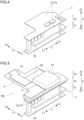
- FIG. 1 is a schematic exploded perspective view of a vehicle drive device 1
- FIG. 2 is a skeleton diagram of the vehicle drive device 1
- FIG. 3 illustrates a schematic circuit block diagram of the vehicle drive device 1.
- the vehicle drive device 1 includes a rotary electric machine 8 that includes a rotor 81, output members (a drive shaft DS and a differential side gears 44) that are drivingly connected to wheels W, a power transmission mechanism TM that transmits driving force between the rotary electric machine 8 and the output members, an inverter module 5, a power source module 7, and a case 9.
- the inverter module 5 is a circuit module for drive-controlling the rotary electric machine 8.
- the power source module 7 is a circuit module of a power source system that is electrically connected to an in-vehicle battery (high-voltage battery BH).
- the case 9 is formed including a case body 91, a first side cover 92, a second side cover 93, and an upper cover 94, and a housing space is formed in a space surrounded by the case body 91, the first side cover 92, the second side cover 93, and the upper cover 94.
- being drivingly connected means a state in which two rotational elements are connected to each other in such a manner that driving force can be transmitted therebetween, and includes a state in which the two rotational elements are connected to each other in such a manner as to integrally rotate or a state in which the two rotational elements are coupled to each other in such a manner that driving force can be transmitted therebetween via one or two or more transmission members.
- a transmission member include various types of members that transmits rotation at the same speed or by changing speed, such as a shaft, a gear mechanism, a belt, and a chain.
- the transmission member may include an engagement device that selectively transmits rotation and driving force, such as a friction engagement device and a gearing type engagement device.
- integrally rotate means integrally rotating regardless of whether separably or inseparably rotating. That is, a plurality of members that integrally rotate may be integrally formed of the same member or may be formed of separate members and integrated by welding, spline connection, or the like.
- two elements "overlapping each other in a specific direction view” with regard to an arrangement of the two element means that when a virtual straight line that is parallel with the view direction is moved in respective directions orthogonal to the virtual straight line, at least some area in which the virtual straight line crosses both of the two elements exists.
- each differential pinion gear integrally rotate with the differential case, and each differential pinion gear is configured to be rotatable about a corresponding pinion shaft and revolvable about a rotational axis of the differential case (herein, the first axis A1).
- the plurality of pinion shafts are arranged in a radial manner (for example, in a cross shape) with the rotational axis of the differential case at the center, and to each of the plurality of pinion shafts, a differential pinion gear is attached.
- the differential case houses the pinion gears, the differential side gears 44, and the pinion shafts thereinside.
- the differential case integrally rotates with the differential ring gear 41.
- the differential side gears 44 and the drive shaft DS are equivalent to the output members in the vehicle drive device 1.
- the output axis that is a rotational axis of the output members is also the first axis A1. That is, the vehicle drive device 1 of the present embodiment has a two axis configuration in which the output axis that is the rotational axis of the output members is arranged on the first axis A1 that is coaxial with the rotor axis and the offset gear mechanism is arranged on the offset axis (the second axis A2).
- the rotary electric machine 8 functions as a driving force source of the pair of wheels W. As illustrated in FIG. 3 , the rotary electric machine 8 is electrically connected, via an inverter 50, to a high-voltage battery BH that is a DC power source formed of a chargeable secondary battery, such as a lithium-ion battery, or a power storage device, such as an electric double layer capacitor. Between the high-voltage battery BH and the inverter 50, a first DC link capacitor 61 that functions as a smoothing capacitor that smooths voltage on a DC side of the inverter 50 is installed.
- a high-voltage battery BH that is a DC power source formed of a chargeable secondary battery, such as a lithium-ion battery, or a power storage device, such as an electric double layer capacitor.
- a first DC link capacitor 61 that functions as a smoothing capacitor that smooths voltage on a DC side of the inverter 50 is installed.
- the rotary electric machine 8 has a function as a motor that generates motive power upon receiving supply of electric power from the high-voltage battery BH and a function as a generator that generates electric power upon receiving supply of motive power from a wheel W side.
- the rotary electric machine 8 performs power running using electric power stored in the high-voltage battery BH and thereby generates driving force, and also generates electric power using driving force transmitted from the pair of wheel W sides and thereby charges the high-voltage battery BH.
- a rated voltage of the high-voltage battery BH is approximately 200 to 800 volts.
- the traction rotary electric machine differs from an internal-combustion engine that is constantly in motion, such as when idling, even when the vehicle stops (when the vehicle is in a state in which the wheels do not rotate), the traction rotary electric machine ceases to move when the vehicle stops. Since a mechanical oil pump that requires motive power of an internal-combustion engine to suck and discharge oil cannot supply oil for lubrication or oil for cooling while the vehicle using the traction rotary electric machine is standing still and an electric oil pump is thus used, the output required for the auxiliary machine rotary electric machine also tends to increase.
- the auxiliary machine rotary electric machine M is, as with the traction rotary electric machine, supplied with electric power from the high-voltage battery BH has increased.
- the rated voltage of the high-voltage battery BH tends to become higher.
- a voltage conversion circuit that steps down DC power supplied from the high-voltage battery BH is installed.
- a configuration that includes a first DC-DC converter 75 as such a voltage conversion circuit is exemplified.
- a second DC link capacitor 62 is also installed to smooth DC voltage.
- the high-voltage battery BH is configured to be chargeable by not only electric power that the rotary electric machine 8 generates but also electric power supplied from an external AC power source, such as a commercial AC power source having a rated voltage of approximately 100 to 240 volts.
- the high-voltage battery BH is configured to be connectable to an external power source via an in-vehicle charging device 70 including a charging circuit.
- the in-vehicle charging device 70 is configured including not only a function of the charging circuit but also a function of a power supply circuit. Needless to say, the in-vehicle charging device 70 may be configured including only the function of the charging circuit.
- the above-described emergency power source is often installed to be able to output AC power to a point to which an external AC power source is connected, that is, to the outside of the vehicle.
- some vehicles include an AC power supply socket to supply electric power to a general low-power-consumption household appliance or the like in a vehicle interior.
- a power supply circuit to supply AC power to such an AC power supply socket may be installed.
- the in-vehicle charging device 70 of the present embodiment includes a dual active bridge (DAB) circuit including a transformer T and converts AC power (AC IN) supplied from the external AC power source side to first DC power and second DC power.
- the transformer T When viewed from an AC side, the transformer T includes a primary-side coil and two secondary-side coils.
- a primary-side circuit 71 is formed by connecting a full-bridge circuit formed of switching elements to the primary-side coil.
- a first secondary-side circuit 72 is formed by connecting a full-bridge circuit to a first secondary-side coil
- a second secondary-side circuit 73 is also formed by connecting a full-bridge circuit to a second secondary-side coil.
- the first secondary-side circuit 72 generates the first DC power to charge the high-voltage battery BH.
- a third DC link capacitor 63 that smooths voltage of the first DC power is installed.
- the second secondary-side circuit 73 generates the second DC power having a lower voltage than the first DC power.
- a fourth DC link capacitor 64 that smooths voltage of the second DC power is installed.
- the vehicle includes, in addition to the high-voltage battery BH, a low-voltage battery BL that has a lower rated voltage than the high-voltage battery BH.
- a rated power source voltage of the low-voltage battery BL is, for example, approximately 12 to 24 volts.
- a low-voltage battery BL has been charged with electric power generated by an alternator using motive power of the internal-combustion engine.
- the vehicle of the present embodiment that includes the high-voltage battery BH is configured to be able to charge the low-voltage battery BL with electric power supplied from the high-voltage battery BH or an external AC power source.
- the vehicle of the present embodiment is able to charge the low-voltage battery BL from the high-voltage battery BH via the first secondary-side circuit 72, the transformer T, and the second secondary-side circuit 73 or from the external AC power source via the primary-side circuit 71, the transformer T, and the second secondary-side circuit 73.
- a mode in which a second DC-DC converter 76 is installed as a voltage conversion circuit that further steps down the voltage of the second DC power is exemplified.
- the low-voltage battery BL may be a lead-acid storage battery as with a conventional vehicle using an internal-combustion engine as a driving force source of wheels.
- the in-vehicle charging device 70 is formed using the transformer T, insulation among the external AC power source, the high-voltage battery BH, and the low-voltage battery BL can be secured.
- the external AC power source and the in-vehicle charging device 70 are connected via an electromagnetic interference (EMI) filter 79 that reduces EMI noise.
- EMI electromagnetic interference
- AC power AC OUT
- the power source module 7 is formed including the EMI filter 79, the in-vehicle charging device 70 (the charging circuit and the power supply circuit), and the voltage conversion circuits (the first DC-DC converter 75 and the second DC-DC converter 76).
- the power source module 7 is, without being limited to this mode, only required to be configured including at least one of the charging circuit, the power supply circuit, and the voltage conversion circuits.
- the rotary electric machine 8 is drive-controlled by a rotary electric machine control unit, based on target torque of the rotary electric machine 8 that is set in accordance with a command from a not-illustrated vehicle control device that serves as a higher-level control device.
- the rotary electric machine control unit switching-controls the inverter 50 that is formed of a plurality of switching elements and thereby causes the inverter 50 to convert electric power between DC and a plurality of phases (in the present embodiment, three phases) of AC.
- the rotary electric machine control unit is configured as an ECU 2 (control device) in conjunction with a charging control unit that controls the in-vehicle charging device 70, a first voltage conversion control unit that control the first DC-DC converter 75, a second voltage conversion control unit that controls the second DC-DC converter 76, and the like.
- the ECU 2 is configured with a processor, such as a microcomputer, as a core component, and operating voltage of the ECU 2 is 3.3 to 5 volts.
- Voltage applied to the inverter 50 which is connected to the high-voltage battery BH, is several hundred volts, and voltage of switching control signals to switching elements that constitute the inverter 50, such as insulated gate bipolar transistors (IGBTs) and power metal oxide semiconductor field effect transistors (MOSFETs), is approximately 15 to 24 volts.
- IGBTs insulated gate bipolar transistors
- MOSFETs power metal oxide semiconductor field effect transistors
- the drive circuit is not illustrated, the inverter module 5 having the inverter 50 as a core component is formed including the drive circuit as described above.
- the inverter module 5 may be configured including at least some of control circuits other than the drive circuit and the first DC link capacitor 61.
- a power circuit assembly PE is configured including the inverter module 5 and the power source module 7.
- a filter board on which the EMI filter 79 is formed is arranged on the lowermost side Z2 in the up-down direction Z, and the in-vehicle charging device 70 and the second DC-DC converter 76 are arranged on the upper side Z1 of the EMI filter 79.
- the inverter module 5 on the power source module 7, the inverter module 5, the first DC link capacitor 61, the first DC-DC converter 75, and the ECU 2 are arranged on the uppermost side Z1 in the up-down direction Z.
- the EMI filter 79 is arranged in a first floor portion F1 in the up-down direction Z
- the in-vehicle charging device 70 and the second DC-DC converter 76 are arranged in a second floor portion F2
- the inverter module 5, the first DC-DC converter 75, the first DC link capacitor 61, and the ECU 2 are arranged in a third floor portion F3.
- the power source module 7 may be formed by combining an L-shaped board, a board expanding along the up-down direction Z, and a board expanding in the axial direction L and the axis-orthogonal direction Y.
- the second DC link capacitor 62, the third DC link capacitor 63, the fourth DC link capacitor 64, and the like are, for example, arranged in the second floor portion F2.
- the second DC link capacitor 62 may be arranged in the third floor portion F3.
- the first DC link capacitor 61 and the second DC link capacitor 62 may be commonly used, integrally formed, and arranged at one point.
- the third DC link capacitor 63 and one or both of the first DC link capacitor 61 and the second DC link capacitor 62 may be commonly used, integrally formed, and arranged at one point. Note that since the DC link capacitors are large in size, the DC link capacitors may be arranged in a distributed manner in both the second floor portion F2 and the third floor portion F3.
- the case 9 includes a first housing chamber E1 for housing the rotary electric machine 8 and the power transmission mechanism TM and a second housing chamber E2 for housing the power circuit assembly PE (the inverter module 5 and the power source module 7), as illustrated in FIG. 1 .
- the first housing chamber E1 and the second housing chamber E2 are partitioned from each other by a partition wall.
- an area in which the rotary electric machine 8 is housed and an area in which the power transmission mechanism is housed may be partitioned from each other by a wall to support a bearing or the like, both areas communicate with each other in some portion even when the areas are partitioned from each other.
- the second housing chamber E2 is not partitioned and the inverter module and the power source module are housed in one chamber
- the second housing chamber E2 may have a wall that partially partitions the second housing chamber E2 into areas as long as the partitioned areas communicate with each other in some portion to secure a path for wiring or the like.
- the second housing chamber E2 includes an upper area E3 that is an area located on the upper side Z1 with respect to the rotary electric machine 8 and overlapping the rotary electric machine 8 in the up-down direction Z view while the vehicle drive device 1 is in an in-vehicle state of being mounted on the vehicle.
- the second housing chamber E2 includes a lateral area E4 that is an area located on the axis-orthogonal direction first side Y1 with respect to the rotary electric machine 8, not overlapping the rotary electric machine 8 in the up-down direction Z view, and overlapping the counter gear mechanism 3, which serves as an offset gear mechanism, in an axial direction L view.
- At least a portion of the inverter module 5 is arranged in the upper area E3, and at least a portion of the power source module 7 is arranged in the lateral area E4.
- the entire inverter module 5 is arranged in the upper area E3.
- a portion of the inverter module 5 may be arranged in a connection area E5, which will be described later, (see FIGS. 1 , 7 , 9 , and the like).
- the power source module 7 is arranged in the upper area E3, the lateral area E4, the connection area E5, and an outer side area E6 (see FIGS. 1 , 8 , 9 , and the like).
- inverter module 5 and the power source module 7 are housed in one second housing chamber E2, sharing of components, such as a DC link capacitor and an ECU, between the inverter module 5 and the power source module 7 can be easily achieved, as is evident from the circuit block diagram in FIG. 3 and a perspective view in FIG. 5 . Thus, reduction in the numbers of components and reduction in weights of the inverter module 5 and the power source module can be easily achieved.
- the inverter module 5 is arranged in the upper area E3 and the power source module 7 is arranged in the lateral area E4, miniaturization in the up-down direction Z of the vehicle drive device 1 can be easily achieved, compared with a configuration in which both the inverter module 5 and the power source module 7 are, for example, arranged in an area located on the upper side Z1 with respect to the rotary electric machine 8.
- the power source module 7 can be arranged by making use of a space that is generated on the axis-orthogonal direction first side Y1 with respect to the rotary electric machine 8 by the counter gear mechanism 3 being arranged, it is easy to prevent the vehicle drive device 1 from becoming larger in size, even when the vehicle drive device 1 further includes the power source module 7 in addition to the rotary electric machine 8, the output members, the power transmission mechanism TM, and the inverter module 5.
- Capacitors and inductors used in the power source module 7 including the in-vehicle charging device 70, the EMI filter 79, and the like are often required to have large capacities as the power source module 7 becomes necessary to deal with a large current. Thus, the capacitors and inductors tend to become larger in size. Since according to the present embodiment, it is easy to secure a large housing space in the up-down direction Z, the vehicle drive device 1 can be prevented from becoming larger in dimension in the up-down direction Z.
- a dimension in the up-down direction Z of the power source module 7 is larger than a dimension in the up-down direction Z of the inverter module 5, and a dimension in the axis-orthogonal direction Y of the inverter module 5 is larger than a dimension in the axis-orthogonal direction Y of the power source module 7.
- the lateral area E4 that is an area located on the axis-orthogonal direction first side Y1 with respect to the rotary electric machine 8 and not overlapping the rotary electric machine 8 in the up-down direction Z view overlaps the counter gear mechanism 3 in the axial direction L view.
- the lateral area E4 can be disposed over a wide range in an arrangement area in the up-down direction Z of the rotary electric machine 8, and even when a wider area than the upper area E3 is secured in the up-down direction Z, a dimension in the up-down direction Z of the vehicle drive device 1 can be easily prevented from increasing.
- the upper area E3 that overlaps the rotary electric machine 8 in the up-down direction Z view can be disposed over a substantially whole area in the axis-orthogonal direction Y above the rotary electric machine 8. That is, an expanse in the axis-orthogonal direction Y of the upper area E3 that is equivalent to a diameter of the rotary electric machine 8 can be easily secured.
- a larger area in the up-down direction Z than the upper area E3 can be easily secured for the lateral area E4, and a larger area in the axis-orthogonal direction Y than the lateral area E4 can be easily secured for the upper area E3.
- the inverter module 5 since at least a portion of the power source module 7 that has a larger dimension in the up-down direction Z than the inverter module 5 is arranged in the lateral area E4 in which a dimension in the up-down direction Z can be more easily secured than in the upper area E3, miniaturization in the up-down direction Z of the vehicle drive device 1 can be easily achieved.
- the inverter module 5 since at least a portion of the inverter module 5 that has a smaller dimension in the up-down direction Z and has a larger dimension in the axis-orthogonal direction Y than the power source module 7 is arranged in the upper area E3, the inverter module 5 can be appropriately arranged while the vehicle drive device 1 is prevented from becoming larger in size.
- connection area E5 is located on the axis-orthogonal direction first side Y1 with respect to the upper area E3 and on the upper side Z1 in the up-down direction Z with respect to the lateral area E4. Note that a portion of the upper area E3 on the axis-orthogonal direction first side Y1 and a portion of the lateral area E4 on the upper side Z1 may be included in the connection area E5. As is evident from FIGS.
- shared components shared by the inverter module 5 and the power source module 7, such as the ECU 2 and the first DC link capacitor 61, are arranged in the connection area E5 in which the upper area E3 and the lateral area E4 are connected.
- sharing components between the inverter module 5 and the power source module 7 enables reduction in the combined number of components and reduction in combined weight of the inverter module 5 and the power source module 7 to be easily achieved.
- sharing components are arranged in the connection area E5, in which the upper area E3 and the lateral area E4 are connected, both connection between the shared components and the inverter module 5 and connection between the shared components and the power source module 7 can be easily appropriately performed.
- the first DC link capacitor 61, the second DC link capacitor 62, and the third DC link capacitor 63 can be formed of the same capacitor.
- the capacitor being arranged in the connection area E5 enables wiring to be short when the capacitor is shared between the inverter module 5 and the first DC-DC converter 75 in the power source module 7 and between the inverter module 5 and the first secondary-side circuit 72 in the power source module 7.
- the ECU 2 switching-controls switching elements constituting the inverter 50 and the first DC-DC converter 75 and switching elements constituting the DAB in the in-vehicle charging device 70.
- the ECU 2 being arranged in the connection area E5 enables wiring to the ECU 2 to be short.
- the pair of differential side gears 44 are equivalent to the output members.
- the differential side gears 44 are arranged on the axial direction first side L1 with respect to the rotary electric machine 8.
- a dimension in the axial direction L of the counter gear mechanism 3 which serves as an offset gear mechanism is smaller than a dimension in the axial direction L of the rotary electric machine 8.
- the counter gear mechanism 3 is arranged on the axial direction first side with respect to the rotary electric machine 8.
- the offset gear mechanism such as the counter gear mechanism 3 is only required to have at least a portion thereof arranged on the axial direction first side with respect to the rotary electric machine 8.
- the lateral area E4 is formed on the axial direction second side L2 with respect to the counter gear mechanism 3.
- the second housing chamber E2 further includes the outer side area E6 that continues from the lateral area E4 on the axis-orthogonal direction first side Y1 with respect to the lateral area E4.
- a target portion 7T (see FIG. 8 ) that is a portion of the power source module 7 is arranged.
- the target portion 7T is arranged to overlap the counter gear mechanism 3 in an axis-orthogonal direction view along the axis-orthogonal direction Y.
- the target portion 7T is equivalent to a portion that is arranged on the upper side Z1 of the first floor portion F1 and in the second floor portion F2.
- At least a portion of the offset gear mechanism (for example, the counter gear mechanism 3) is arranged on the axial direction first side L1 with respect to the rotary electric machine 8 to transmit driving force between the offset gear mechanism and the output members arranged coaxially with the rotary electric machine 8.
- the lateral area E4 is located in an area that overlaps the offset gear mechanism (the counter gear mechanism 3) in the axial direction L view.
- the power source module 7 can be arranged using a dead space generated on the axis-orthogonal direction first side Y1 with respect to the rotary electric machine 8 and on the axial direction second side L2 with respect to the offset gear mechanism (the counter gear mechanism 3) due to the dimension and arrangement of the offset gear mechanism (the counter gear mechanism 3) with respect to the rotary electric machine 8. Therefore, the vehicle drive device 1 can be effectively prevented from becoming larger in size due to including the power source module 7.
- a portion of the power source module 7 can be arranged using an area that is located on the axis-orthogonal direction first side Y1 of the offset gear mechanism (the counter gear mechanism 3) and that overlaps the offset gear mechanism in the axis-orthogonal direction Y view. That is, in the outer side area E6, which continues from the lateral area E4, the target portion 7T of the power source module 7 can be arranged. Therefore, in this respect, the vehicle drive device 1 can also be effectively prevented from becoming larger in size due to including the power source module 7.
- capacitors and inductors used in the power source module 7 including the in-vehicle charging device 70, the EMI filter 79, and the like are often required to have large capacities as the power source module 7 becomes necessary to deal with a large current.
- the capacitors and inductors tend to become larger in size, according to the present embodiment, such components can be appropriately housed, using a dead space. Therefore, while the size of the vehicle drive device 1 is suppressed to be small, a large number of devices can be housed.
- the vehicle drive device 1 that houses the rotary electric machine 8, the output members, the power transmission mechanism TM, the inverter module 5, and the power source module 7 in the same case 9 can be formed smaller in size.
Landscapes
- Engineering & Computer Science (AREA)
- Mechanical Engineering (AREA)
- Power Engineering (AREA)
- Transportation (AREA)
- Chemical & Material Sciences (AREA)
- Combustion & Propulsion (AREA)
- General Engineering & Computer Science (AREA)
- Microelectronics & Electronic Packaging (AREA)
- Electric Propulsion And Braking For Vehicles (AREA)
- Arrangement Or Mounting Of Propulsion Units For Vehicles (AREA)
- Gear Transmission (AREA)
- General Details Of Gearings (AREA)
Abstract
Description
- This disclosure generally relates to a vehicle drive device.
- In
JP2021-48748A - A rotation shaft (14) of the rotary electric machine (11A) and the output shaft (15) are different shafts that are parallel with each other. Therefore, it is interpreted that a gear for transmitting motive power between the rotation shaft (14) and the output shaft (15) is arranged on an axis that is parallel with and different from the rotation shaft (14) and the output shaft (15). Alternatively, it is interpreted that motive power is transmitted between the rotation shaft (14) and the output shaft (15) by a belt, a chain, or the like. In addition, the power drive unit (28) is housed in a first housing chamber (21) in the case (13), and the voltage converter (29) is housed in a second housing chamber (22) in the case (13). The first housing chamber (21) is disposed on an upper side of the rotary electric machine (11A), and the second housing chamber (22) is disposed on a lateral side of the first housing chamber (21).
- When the first housing chamber (21) and the second housing chamber (22) are separated from each other as described above, it is required to secure a housing space in the first housing chamber (21) according to a size of the power drive unit (28) and also secure a housing space in the second housing chamber (22) according to a size of the voltage converter (29), and thus miniaturization of the case (13), that is, miniaturization of the vehicle drive device, is restricted. Conversely, when the power drive unit (28) is formed according to the housing space in the first housing chamber (21) and the voltage converter (29) is formed according to the housing space in the second housing chamber (22), there are cases where performance required for a circuit becomes difficult to secure or it becomes necessary to form the circuit by using expensive components for miniaturization. Specifically, when the first housing chamber (21) and the second housing chamber (22) are separated from each other, flexibility for arrangement and configuration of the power drive unit (28) and the voltage converter (29) tends to deteriorate.
- A need thus exists for a vehicle drive device to be formed smaller in size that houses a rotary electric machine, an output member, a power transmission mechanism that transmits driving force between the rotary electric machine and the output member, a circuit module that drive-controls the rotary electric machine, and a power source module in the same case.
- In view of the foregoing, a vehicle drive device includes: a rotary electric machine including a rotor; an output member being drivingly connected to a wheel; a power transmission mechanism that transmits driving force between the rotary electric machine and the output member; an inverter module for drive-controlling the rotary electric machine; a power source module that is electrically connected to an in-vehicle battery and includes at least one of a voltage conversion circuit that performs conversion of voltage of the in-vehicle battery, a charging circuit for performing charging from an external power source to the in-vehicle battery, and a power supply circuit for performing power supply from the in-vehicle battery to an outside; and a case including a first housing chamber that houses the rotary electric machine and the power transmission mechanism, and a second housing chamber that houses the inverter module and the power source module, and when a direction along a rotor axis being a rotational axis of the rotor is defined as an axial direction, a direction orthogonal to the rotor axis in an up-down direction view is defined as an axis-orthogonal direction, and one side in the axis-orthogonal direction is defined as an axis-orthogonal direction first side, an output axis being a rotational axis of the output member is arranged coaxially with the rotor axis, the power transmission mechanism includes an offset gear mechanism being arranged on an offset axis being located on the axis-orthogonal direction first side with respect to the rotor axis and the output axis, the second housing chamber includes, while the vehicle drive device is in an in-vehicle state of being mounted on a vehicle, an upper area being an area being located on an upper side with respect to the rotary electric machine and overlapping the rotary electric machine in an up-down direction view, and a lateral area being an area being located on the axis-orthogonal direction first side with respect to the rotary electric machine, not overlapping the rotary electric machine in an up-down direction view, and overlapping the offset gear mechanism in an axial direction view, at least a part of the inverter module is arranged in the upper area, and at least a part of the power source module is arranged in the lateral area.
- According to the present configuration, since the power source module and the inverter module being a circuit module drive-controlling the rotary electric machine are housed in one second housing chamber, sharing of a component between, for example, the inverter module and the power source module can be achieved. Thus, reduction in the numbers of components and reduction in weights of the inverter module and the power source module can be easily achieved. In addition, according to the present configuration, the inverter module is arranged in the upper area being located on the upper side with respect to the rotary electric machine in the second housing chamber, and the power source module is arranged in the lateral area being located on the axis-orthogonal direction first side with respect to the rotary electric machine in the second housing chamber. Specifically, miniaturization in the up-down direction of the vehicle drive device can be easily achieved, compared with a configuration in which both the inverter module and the power source module are, for example, arranged in an area located on the upper side of the rotary electric machine. Further, according to the present configuration, the power source module can be arranged by using a space generated on the axis-orthogonal direction first side with respect to the rotary electric machine due to arrangement of the offset gear mechanism. Therefore, it is easy to prevent the vehicle drive device from becoming larger in size due to the vehicle drive device further including the power source module in addition to the rotary electric machine, the output member, the power transmission mechanism, and the inverter module. Specifically, according to the present configuration, the vehicle drive device that houses the rotary electric machine, the output member, the power transmission mechanism that transmits driving force between the rotary electric machine and the output member, the circuit module that drive-controls the rotary electric machine, and the power source module in the same case can be formed smaller in size.
- The foregoing and additional features and characteristics of this disclosure will become more apparent from the following detailed description considered with the reference to the accompanying drawings, wherein:
-
FIG. 1 is a schematic exploded perspective view of a vehicle drive device; -
FIG. 2 is a skeleton diagram of the vehicle drive device; -
FIG. 3 is a schematic circuit block diagram of the vehicle drive device; -
FIG. 4 is a schematic perspective view of a power source module; -
FIG. 5 is a schematic perspective view of a power system assy; -
FIG. 6 is a schematic top view of the vehicle drive device while a third cover is removed; -
FIG. 7 is a schematic axially orthogonal cross-sectional view of the vehicle drive device viewed from an axial direction first side; -
FIG. 8 is another schematic axially orthogonal cross-sectional view of the vehicle drive device viewed from the axial direction first side; and -
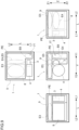
FIG. 9 is a schematic four side view of the vehicle drive device. - An embodiment of a vehicle drive device will be described below with reference to the drawings.
FIG. 1 is a schematic exploded perspective view of avehicle drive device 1,FIG. 2 is a skeleton diagram of thevehicle drive device 1, andFIG. 3 illustrates a schematic circuit block diagram of thevehicle drive device 1. As illustrated inFIGS. 1 and2 , thevehicle drive device 1 includes a rotaryelectric machine 8 that includes arotor 81, output members (a drive shaft DS and a differential side gears 44) that are drivingly connected to wheels W, a power transmission mechanism TM that transmits driving force between the rotaryelectric machine 8 and the output members, aninverter module 5, apower source module 7, and acase 9. Theinverter module 5 is a circuit module for drive-controlling the rotaryelectric machine 8. Thepower source module 7 is a circuit module of a power source system that is electrically connected to an in-vehicle battery (high-voltage battery BH). Thecase 9 is formed including acase body 91, afirst side cover 92, asecond side cover 93, and anupper cover 94, and a housing space is formed in a space surrounded by thecase body 91, thefirst side cover 92, thesecond side cover 93, and theupper cover 94. - Note that as used herein, "being drivingly connected" means a state in which two rotational elements are connected to each other in such a manner that driving force can be transmitted therebetween, and includes a state in which the two rotational elements are connected to each other in such a manner as to integrally rotate or a state in which the two rotational elements are coupled to each other in such a manner that driving force can be transmitted therebetween via one or two or more transmission members. Examples of such a transmission member include various types of members that transmits rotation at the same speed or by changing speed, such as a shaft, a gear mechanism, a belt, and a chain. Note that examples of the transmission member may include an engagement device that selectively transmits rotation and driving force, such as a friction engagement device and a gearing type engagement device. In addition, as used herein, "integrally rotate" means integrally rotating regardless of whether separably or inseparably rotating. That is, a plurality of members that integrally rotate may be integrally formed of the same member or may be formed of separate members and integrated by welding, spline connection, or the like. In addition, as used herein, two elements "overlapping each other in a specific direction view" with regard to an arrangement of the two element means that when a virtual straight line that is parallel with the view direction is moved in respective directions orthogonal to the virtual straight line, at least some area in which the virtual straight line crosses both of the two elements exists.
- In the present embodiment, a direction along a rotor axis (first axis A1) that is a rotational axis of the
rotor 81 is defined as an axial direction L. In addition, one side in the axial direction L is defined as an axial direction first side L1 and the other side in the axial direction L is defined as an axial direction second side L2. In addition, in the present embodiment, a direction along a vertical direction while thevehicle drive device 1 is in a state of being mounted on a vehicle in a standard posture is defined as an up-down direction Z, and an upper side and a lower side in the up-down direction Z are defined as an upper side Z1 and a lower side Z2, respectively. In other words, the up-down direction Z is a direction in thevehicle drive device 1, and when thevehicle drive device 1 is mounted on the vehicle in the standard posture, the up-down direction Z coincides with the vertical direction. Therefore, when thevehicle drive device 1 is mounted on the vehicle while being inclined with respect to the standard posture, the up-down direction Z sometimes does not coincide with the vertical direction. An angle of the inclination is not prevented from exceeding 90 degrees. In addition, a direction orthogonal to the rotor axis (first axis A1) in an up-down direction Z view is defined as an axis-orthogonal direction Y, and one side in the axis-orthogonal direction Y is defined as an axis-orthogonal direction first side Y1 and the other side in the axis-orthogonal direction Y is defined as an axis-orthogonal direction second side Y2. - As illustrated in the skeleton diagram in
FIG. 2 , the rotaryelectric machine 8 is an inner rotor-type rotary electric machine that includes astator 82 fixed to thecase 9 and therotor 81 arranged on an inner side in a radial direction of thestator 82. On thestator 82, astator coil 83 is wound. Therotor 81 is coupled to therotor shaft 88 arranged on the inner side in the radial direction of therotor 81, and therotor 81 and therotor shaft 88 integrally rotate. In the present embodiment, therotor shaft 88 is a hollow cylindrical member, and as described later, on the inner side in the radial direction of therotor shaft 88, the drive shaft DS (which may be a connection member, as described later) penetrates. Therotor shaft 88, therotor 81, and the drive shaft DS are arranged on the first axis A1. On therotor shaft 88, aninput gear 89 is integrally formed. Theinput gear 89 and therotor shaft 88 may be integrally formed of the same member or formed of separate members and joined by welding or the like. - The
input gear 89 meshes with afirst counter gear 31. Thefirst counter gear 31 integrally rotates with asecond counter gear 32 that has a smaller diameter than thefirst counter gear 31. Because of this configuration, speed of rotation transmitted from therotor shaft 88 to thefirst counter gear 31 via theinput gear 89 is reduced and the rotation is output from thesecond counter gear 32. Thefirst counter gear 31 and thesecond counter gear 32 constitute acounter gear mechanism 3 that functions as a reduction gear. Thecounter gear mechanism 3 is arranged on a second axis A2 that is parallel with the first axis A1 and that is a separate axis from the first axis A1. As illustrated inFIGS. 7 and 8 , the second axis A2 is located on the axis-orthogonal direction first side Y1 with respect to the first axis A1. Therefore, it can be said that the second axis A2 is an offset axis that is offset to the axis-orthogonal direction first side Y1 with respect to the first axis A1 (the rotor axis and an output axis, which will be described later). It can also be said that thecounter gear mechanism 3 arranged on the second axis A2 (the offset axis) is an offset gear mechanism. In addition, in the present embodiment, thecounter gear mechanism 3 is arranged on the axial direction first side L1 with respect to the rotaryelectric machine 8. - The
second counter gear 32 meshes with adifferential ring gear 41 that is an input gear (differential input gear) to adifferential gear mechanism 4. Although illustration is omitted since a configuration of thedifferential gear mechanism 4 is a known configuration, thedifferential gear mechanism 4 is a bevel gear-type differential gear mechanism and includes differential pinion gears each of which is a bevel gear and the differential side gears 44. The differential pinion gears are supported by a differential case and are also rotatably supported by pinion shafts that are arranged in such a manner as to extend in radial directions. The pinion shafts integrally rotate with the differential case, and each differential pinion gear is configured to be rotatable about a corresponding pinion shaft and revolvable about a rotational axis of the differential case (herein, the first axis A1). The plurality of pinion shafts are arranged in a radial manner (for example, in a cross shape) with the rotational axis of the differential case at the center, and to each of the plurality of pinion shafts, a differential pinion gear is attached. The differential case houses the pinion gears, the differential side gears 44, and the pinion shafts thereinside. The differential case integrally rotates with thedifferential ring gear 41. - The differential side gears 44 are arranged in a pair separated from each other on the axial direction first side L1 and the axial direction second side L2. Each of the pair of differential side gears 44 is arranged in such a manner as to mesh with the plurality of pinion gears and also rotate about the rotational axis of the differential case. As illustrated in
FIG. 2 , thedifferential side gear 44 on the axial direction first side L1 is coupled to the drive shaft DS on the axial direction first side L1 and is drivingly connected to a wheel W on the axial direction first side L1. Thedifferential side gear 44 on the axial direction second side L2 is coupled to the drive shaft DS on the axial direction second side L2 and is drivingly connected to a wheel W on the axial direction second side L2. Note that since thedifferential gear mechanism 4 is arranged on the axial direction first side L1 with respect to the rotaryelectric machine 8, the drive shaft DS on the axial direction second side L2 penetrates the inner side in the radial direction of the hollowcylindrical rotor shaft 88 and extends to the axial direction second side L2 of the rotaryelectric machine 8. The drive shaft DS on the axial direction second side L2 may be formed of a member (a so-called drive shaft) drivingly connected to the wheel W and a connection member that is connected to thedifferential side gear 44 and that connects the member and thedifferential side gear 44. - The differential side gears 44 and the drive shaft DS are equivalent to the output members in the
vehicle drive device 1. In the present embodiment, the output axis that is a rotational axis of the output members is also the first axis A1. That is, thevehicle drive device 1 of the present embodiment has a two axis configuration in which the output axis that is the rotational axis of the output members is arranged on the first axis A1 that is coaxial with the rotor axis and the offset gear mechanism is arranged on the offset axis (the second axis A2). - The rotary
electric machine 8 functions as a driving force source of the pair of wheels W. As illustrated inFIG. 3 , the rotaryelectric machine 8 is electrically connected, via aninverter 50, to a high-voltage battery BH that is a DC power source formed of a chargeable secondary battery, such as a lithium-ion battery, or a power storage device, such as an electric double layer capacitor. Between the high-voltage battery BH and theinverter 50, a firstDC link capacitor 61 that functions as a smoothing capacitor that smooths voltage on a DC side of theinverter 50 is installed. - The rotary
electric machine 8 has a function as a motor that generates motive power upon receiving supply of electric power from the high-voltage battery BH and a function as a generator that generates electric power upon receiving supply of motive power from a wheel W side. The rotaryelectric machine 8 performs power running using electric power stored in the high-voltage battery BH and thereby generates driving force, and also generates electric power using driving force transmitted from the pair of wheel W sides and thereby charges the high-voltage battery BH. A rated voltage of the high-voltage battery BH is approximately 200 to 800 volts. - As described above, the rotary
electric machine 8 is a driving force source of wheels and is a so-called traction rotary electric machine. A vehicle sometimes includes an auxiliary machine rotary electric machine M that serves as a driving force source of an auxiliary machine, such as an air conditioner and an electric oil pump, in addition to a traction rotary electric machine. Although in a conventional vehicle that uses only an internal-combustion engine as a driving force source of wheels, waste heat from the internal-combustion engine can be used for an air conditioner, in a hybrid vehicle or an electric vehicle, use of as much waste heat as the internal-combustion engine cannot be expected, temperature adjustment by a heat pump or the like is required, and output required for the auxiliary machine rotary electric machine tends to increase. In addition, differing from an internal-combustion engine that is constantly in motion, such as when idling, even when the vehicle stops (when the vehicle is in a state in which the wheels do not rotate), the traction rotary electric machine ceases to move when the vehicle stops. Since a mechanical oil pump that requires motive power of an internal-combustion engine to suck and discharge oil cannot supply oil for lubrication or oil for cooling while the vehicle using the traction rotary electric machine is standing still and an electric oil pump is thus used, the output required for the auxiliary machine rotary electric machine also tends to increase. - The number of vehicles that are configured such that to cause the auxiliary machine rotary electric machine M to output a large driving force, the auxiliary machine rotary electric machine M is, as with the traction rotary electric machine, supplied with electric power from the high-voltage battery BH has increased. On the other hand, as output required for the traction rotary electric machine increases, the rated voltage of the high-voltage battery BH tends to become higher. Thus, in some cases, when the rated voltage of the high-voltage battery BH is too high for the auxiliary machine rotary electric machine M, a voltage conversion circuit that steps down DC power supplied from the high-voltage battery BH is installed. In the present embodiment, a configuration that includes a first DC-
DC converter 75 as such a voltage conversion circuit is exemplified. On the high-voltage battery BH side of the first DC-DC converter 75, a secondDC link capacitor 62 is also installed to smooth DC voltage. - Note that in the present embodiment, the high-voltage battery BH is configured to be chargeable by not only electric power that the rotary
electric machine 8 generates but also electric power supplied from an external AC power source, such as a commercial AC power source having a rated voltage of approximately 100 to 240 volts. Thus, the high-voltage battery BH is configured to be connectable to an external power source via an in-vehicle charging device 70 including a charging circuit. In addition, recent years, using a battery mounted on an electric vehicle or a hybrid vehicle as an emergency power source at the time of a disaster or the like has been proposed. Therefore, in the present embodiment, the in-vehicle charging device 70 is configured including not only a function of the charging circuit but also a function of a power supply circuit. Needless to say, the in-vehicle charging device 70 may be configured including only the function of the charging circuit. - The above-described emergency power source is often installed to be able to output AC power to a point to which an external AC power source is connected, that is, to the outside of the vehicle. On the other hand, some vehicles include an AC power supply socket to supply electric power to a general low-power-consumption household appliance or the like in a vehicle interior. A power supply circuit to supply AC power to such an AC power supply socket may be installed.
- The in-
vehicle charging device 70 of the present embodiment includes a dual active bridge (DAB) circuit including a transformer T and converts AC power (AC IN) supplied from the external AC power source side to first DC power and second DC power. When viewed from an AC side, the transformer T includes a primary-side coil and two secondary-side coils. For example, a primary-side circuit 71 is formed by connecting a full-bridge circuit formed of switching elements to the primary-side coil. Likewise, a first secondary-side circuit 72 is formed by connecting a full-bridge circuit to a first secondary-side coil, and a second secondary-side circuit 73 is also formed by connecting a full-bridge circuit to a second secondary-side coil. - The first secondary-
side circuit 72 generates the first DC power to charge the high-voltage battery BH. In an output portion of the first secondary-side circuit 72, a thirdDC link capacitor 63 that smooths voltage of the first DC power is installed. The second secondary-side circuit 73 generates the second DC power having a lower voltage than the first DC power. In an output portion of the second secondary-side circuit 73, a fourthDC link capacitor 64 that smooths voltage of the second DC power is installed. - As illustrated in
FIG. 3 , the vehicle includes, in addition to the high-voltage battery BH, a low-voltage battery BL that has a lower rated voltage than the high-voltage battery BH. A rated power source voltage of the low-voltage battery BL is, for example, approximately 12 to 24 volts. In conventional vehicles that use only an internal-combustion engine as a driving force source of wheels W, such a low-voltage battery BL has been charged with electric power generated by an alternator using motive power of the internal-combustion engine. The vehicle of the present embodiment that includes the high-voltage battery BH is configured to be able to charge the low-voltage battery BL with electric power supplied from the high-voltage battery BH or an external AC power source. The vehicle of the present embodiment is able to charge the low-voltage battery BL from the high-voltage battery BH via the first secondary-side circuit 72, the transformer T, and the second secondary-side circuit 73 or from the external AC power source via the primary-side circuit 71, the transformer T, and the second secondary-side circuit 73. In the present embodiment, a mode in which a second DC-DC converter 76 is installed as a voltage conversion circuit that further steps down the voltage of the second DC power is exemplified. Note that the low-voltage battery BL may be a lead-acid storage battery as with a conventional vehicle using an internal-combustion engine as a driving force source of wheels. - In the present embodiment, since, as described above with reference to
FIG. 3 , the in-vehicle charging device 70 is formed using the transformer T, insulation among the external AC power source, the high-voltage battery BH, and the low-voltage battery BL can be secured. - In addition, the external AC power source and the in-
vehicle charging device 70 are connected via an electromagnetic interference (EMI)filter 79 that reduces EMI noise. When the in-vehicle charging device 70 functions as a power supply circuit, AC power (AC OUT) is also output from the in-vehicle charging device 70 via theEMI filter 79. In the present embodiment, thepower source module 7 is formed including theEMI filter 79, the in-vehicle charging device 70 (the charging circuit and the power supply circuit), and the voltage conversion circuits (the first DC-DC converter 75 and the second DC-DC converter 76). Thepower source module 7 is, without being limited to this mode, only required to be configured including at least one of the charging circuit, the power supply circuit, and the voltage conversion circuits. - The rotary
electric machine 8 is drive-controlled by a rotary electric machine control unit, based on target torque of the rotaryelectric machine 8 that is set in accordance with a command from a not-illustrated vehicle control device that serves as a higher-level control device. The rotary electric machine control unit switching-controls theinverter 50 that is formed of a plurality of switching elements and thereby causes theinverter 50 to convert electric power between DC and a plurality of phases (in the present embodiment, three phases) of AC. In the present embodiment, the rotary electric machine control unit is configured as an ECU 2 (control device) in conjunction with a charging control unit that controls the in-vehicle charging device 70, a first voltage conversion control unit that control the first DC-DC converter 75, a second voltage conversion control unit that controls the second DC-DC converter 76, and the like. - The
ECU 2 is configured with a processor, such as a microcomputer, as a core component, and operating voltage of theECU 2 is 3.3 to 5 volts. Voltage applied to theinverter 50, which is connected to the high-voltage battery BH, is several hundred volts, and voltage of switching control signals to switching elements that constitute theinverter 50, such as insulated gate bipolar transistors (IGBTs) and power metal oxide semiconductor field effect transistors (MOSFETs), is approximately 15 to 24 volts. Thus, between theECU 2 and theinverter 50, a drive circuit that amplifies voltage of the switching control signals output from theECU 2, increases driving force, and supplies theinverter 50 with the switching control signals is installed. Although inFIG. 3 , the drive circuit is not illustrated, theinverter module 5 having theinverter 50 as a core component is formed including the drive circuit as described above. Theinverter module 5 may be configured including at least some of control circuits other than the drive circuit and the firstDC link capacitor 61. - In the present embodiment, a power circuit assembly PE is configured including the
inverter module 5 and thepower source module 7. As illustrated inFIG. 4 , in thepower source module 7, a filter board on which theEMI filter 79 is formed is arranged on the lowermost side Z2 in the up-down direction Z, and the in-vehicle charging device 70 and the second DC-DC converter 76 are arranged on the upper side Z1 of theEMI filter 79. As illustrated inFIGS. 5 and6 , on thepower source module 7, theinverter module 5, the firstDC link capacitor 61, the first DC-DC converter 75, and theECU 2 are arranged on the uppermost side Z1 in the up-down direction Z. That is, theEMI filter 79 is arranged in a first floor portion F1 in the up-down direction Z, the in-vehicle charging device 70 and the second DC-DC converter 76 are arranged in a second floor portion F2, and theinverter module 5, the first DC-DC converter 75, the firstDC link capacitor 61, and theECU 2 are arranged in a third floor portion F3. - In the present embodiment, as described above with reference to
FIG. 5 , a mode in which thepower source module 7 is configured including a plurality of boards arranged in line in the up-down direction Z is exemplified. However, for example, thepower source module 7 may be formed by combining an L-shaped board, a board expanding along the up-down direction Z, and a board expanding in the axial direction L and the axis-orthogonal direction Y. - Note that although not illustrated in
FIGS. 4 and 5 , it is suitable that the secondDC link capacitor 62, the thirdDC link capacitor 63, the fourthDC link capacitor 64, and the like are, for example, arranged in the second floor portion F2. The secondDC link capacitor 62 may be arranged in the third floor portion F3. In addition, the firstDC link capacitor 61 and the secondDC link capacitor 62 may be commonly used, integrally formed, and arranged at one point. Likewise, the thirdDC link capacitor 63 and one or both of the firstDC link capacitor 61 and the secondDC link capacitor 62 may be commonly used, integrally formed, and arranged at one point. Note that since the DC link capacitors are large in size, the DC link capacitors may be arranged in a distributed manner in both the second floor portion F2 and the third floor portion F3. - A housing form of the power circuit assembly PE in the
case 9 is described below with reference to alsoFIGS. 7 to 9 . Thecase 9 includes a first housing chamber E1 for housing the rotaryelectric machine 8 and the power transmission mechanism TM and a second housing chamber E2 for housing the power circuit assembly PE (theinverter module 5 and the power source module 7), as illustrated inFIG. 1 . The first housing chamber E1 and the second housing chamber E2 are partitioned from each other by a partition wall. Although in the first housing chamber E1, an area in which the rotaryelectric machine 8 is housed and an area in which the power transmission mechanism is housed may be partitioned from each other by a wall to support a bearing or the like, both areas communicate with each other in some portion even when the areas are partitioned from each other. Although in the present embodiment, the second housing chamber E2 is not partitioned and the inverter module and the power source module are housed in one chamber, the second housing chamber E2 may have a wall that partially partitions the second housing chamber E2 into areas as long as the partitioned areas communicate with each other in some portion to secure a path for wiring or the like. - In addition, as illustrated in
FIGS. 1 ,7 ,9 , and the like, the second housing chamber E2 includes an upper area E3 that is an area located on the upper side Z1 with respect to the rotaryelectric machine 8 and overlapping the rotaryelectric machine 8 in the up-down direction Z view while thevehicle drive device 1 is in an in-vehicle state of being mounted on the vehicle. In addition, the second housing chamber E2 includes a lateral area E4 that is an area located on the axis-orthogonal direction first side Y1 with respect to the rotaryelectric machine 8, not overlapping the rotaryelectric machine 8 in the up-down direction Z view, and overlapping thecounter gear mechanism 3, which serves as an offset gear mechanism, in an axial direction L view. At least a portion of theinverter module 5 is arranged in the upper area E3, and at least a portion of thepower source module 7 is arranged in the lateral area E4. As illustrated inFIG. 7 , in the present embodiment, theentire inverter module 5 is arranged in the upper area E3. However, a portion of theinverter module 5 may be arranged in a connection area E5, which will be described later, (seeFIGS. 1 ,7 ,9 , and the like). In addition, in the present embodiment, thepower source module 7 is arranged in the upper area E3, the lateral area E4, the connection area E5, and an outer side area E6 (seeFIGS. 1 ,8 ,9 , and the like). - Since the
inverter module 5 and thepower source module 7 are housed in one second housing chamber E2, sharing of components, such as a DC link capacitor and an ECU, between theinverter module 5 and thepower source module 7 can be easily achieved, as is evident from the circuit block diagram inFIG. 3 and a perspective view inFIG. 5 . Thus, reduction in the numbers of components and reduction in weights of theinverter module 5 and the power source module can be easily achieved. In addition, since theinverter module 5 is arranged in the upper area E3 and thepower source module 7 is arranged in the lateral area E4, miniaturization in the up-down direction Z of thevehicle drive device 1 can be easily achieved, compared with a configuration in which both theinverter module 5 and thepower source module 7 are, for example, arranged in an area located on the upper side Z1 with respect to the rotaryelectric machine 8. In addition, since thepower source module 7 can be arranged by making use of a space that is generated on the axis-orthogonal direction first side Y1 with respect to the rotaryelectric machine 8 by thecounter gear mechanism 3 being arranged, it is easy to prevent thevehicle drive device 1 from becoming larger in size, even when thevehicle drive device 1 further includes thepower source module 7 in addition to the rotaryelectric machine 8, the output members, the power transmission mechanism TM, and theinverter module 5. - Capacitors and inductors used in the
power source module 7 including the in-vehicle charging device 70, theEMI filter 79, and the like are often required to have large capacities as thepower source module 7 becomes necessary to deal with a large current. Thus, the capacitors and inductors tend to become larger in size. Since according to the present embodiment, it is easy to secure a large housing space in the up-down direction Z, thevehicle drive device 1 can be prevented from becoming larger in dimension in the up-down direction Z. - In addition, as illustrated in
FIGS. 4, 5 , and the like, a dimension in the up-down direction Z of thepower source module 7 is larger than a dimension in the up-down direction Z of theinverter module 5, and a dimension in the axis-orthogonal direction Y of theinverter module 5 is larger than a dimension in the axis-orthogonal direction Y of thepower source module 7. - As illustrated in
FIGS. 9 and the like, the lateral area E4 that is an area located on the axis-orthogonal direction first side Y1 with respect to the rotaryelectric machine 8 and not overlapping the rotaryelectric machine 8 in the up-down direction Z view overlaps thecounter gear mechanism 3 in the axial direction L view. Thus, the lateral area E4 can be disposed over a wide range in an arrangement area in the up-down direction Z of the rotaryelectric machine 8, and even when a wider area than the upper area E3 is secured in the up-down direction Z, a dimension in the up-down direction Z of thevehicle drive device 1 can be easily prevented from increasing. In addition, as illustrated inFIGS. 9 and the like, the upper area E3 that overlaps the rotaryelectric machine 8 in the up-down direction Z view can be disposed over a substantially whole area in the axis-orthogonal direction Y above the rotaryelectric machine 8. That is, an expanse in the axis-orthogonal direction Y of the upper area E3 that is equivalent to a diameter of the rotaryelectric machine 8 can be easily secured. In other words, while thevehicle drive device 1 is prevented from becoming larger in size, a larger area in the up-down direction Z than the upper area E3 can be easily secured for the lateral area E4, and a larger area in the axis-orthogonal direction Y than the lateral area E4 can be easily secured for the upper area E3. - According to the present embodiment, since at least a portion of the
power source module 7 that has a larger dimension in the up-down direction Z than theinverter module 5 is arranged in the lateral area E4 in which a dimension in the up-down direction Z can be more easily secured than in the upper area E3, miniaturization in the up-down direction Z of thevehicle drive device 1 can be easily achieved. In addition, since at least a portion of theinverter module 5 that has a smaller dimension in the up-down direction Z and has a larger dimension in the axis-orthogonal direction Y than thepower source module 7 is arranged in the upper area E3, theinverter module 5 can be appropriately arranged while thevehicle drive device 1 is prevented from becoming larger in size. - The upper area E3 and the lateral area E4 are connected via the connection area E5, as illustrated in
FIG. 9 . In other words, the connection area E5 is located on the axis-orthogonal direction first side Y1 with respect to the upper area E3 and on the upper side Z1 in the up-down direction Z with respect to the lateral area E4. Note that a portion of the upper area E3 on the axis-orthogonal direction first side Y1 and a portion of the lateral area E4 on the upper side Z1 may be included in the connection area E5. As is evident fromFIGS. 1 ,5 ,9 , and the like, in the present embodiment, shared components shared by theinverter module 5 and thepower source module 7, such as theECU 2 and the firstDC link capacitor 61, are arranged in the connection area E5 in which the upper area E3 and the lateral area E4 are connected. - According to this configuration, sharing components between the
inverter module 5 and thepower source module 7 enables reduction in the combined number of components and reduction in combined weight of theinverter module 5 and thepower source module 7 to be easily achieved. In addition, according to the present configuration, since such shared components are arranged in the connection area E5, in which the upper area E3 and the lateral area E4 are connected, both connection between the shared components and theinverter module 5 and connection between the shared components and thepower source module 7 can be easily appropriately performed. - For example, the first
DC link capacitor 61, the secondDC link capacitor 62, and the thirdDC link capacitor 63 can be formed of the same capacitor. The capacitor being arranged in the connection area E5 enables wiring to be short when the capacitor is shared between theinverter module 5 and the first DC-DC converter 75 in thepower source module 7 and between theinverter module 5 and the first secondary-side circuit 72 in thepower source module 7. In addition, theECU 2 switching-controls switching elements constituting theinverter 50 and the first DC-DC converter 75 and switching elements constituting the DAB in the in-vehicle charging device 70. TheECU 2 being arranged in the connection area E5 enables wiring to theECU 2 to be short. - As described above, the pair of differential side gears 44 are equivalent to the output members. In the present embodiment, as illustrated in
FIGS. 1 ,2 , and the like, the differential side gears 44 are arranged on the axial direction first side L1 with respect to the rotaryelectric machine 8. As illustrated inFIGS. 1 ,2 , and9 , a dimension in the axial direction L of thecounter gear mechanism 3, which serves as an offset gear mechanism, is smaller than a dimension in the axial direction L of the rotaryelectric machine 8. In addition, thecounter gear mechanism 3 is arranged on the axial direction first side with respect to the rotaryelectric machine 8. Note that the offset gear mechanism, such as thecounter gear mechanism 3, is only required to have at least a portion thereof arranged on the axial direction first side with respect to the rotaryelectric machine 8. The lateral area E4 is formed on the axial direction second side L2 with respect to thecounter gear mechanism 3. In the present embodiment, as illustrated inFIGS. 1 ,8 ,9 , and the like, the second housing chamber E2 further includes the outer side area E6 that continues from the lateral area E4 on the axis-orthogonal direction first side Y1 with respect to the lateral area E4. In the outer side area E6, atarget portion 7T (seeFIG. 8 ) that is a portion of thepower source module 7 is arranged. Thetarget portion 7T is arranged to overlap thecounter gear mechanism 3 in an axis-orthogonal direction view along the axis-orthogonal direction Y. In the present embodiment, thetarget portion 7T is equivalent to a portion that is arranged on the upper side Z1 of the first floor portion F1 and in the second floor portion F2. - At least a portion of the offset gear mechanism (for example, the counter gear mechanism 3) is arranged on the axial direction first side L1 with respect to the rotary
electric machine 8 to transmit driving force between the offset gear mechanism and the output members arranged coaxially with the rotaryelectric machine 8. The lateral area E4 is located in an area that overlaps the offset gear mechanism (the counter gear mechanism 3) in the axial direction L view. That is, according to the present configuration, thepower source module 7 can be arranged using a dead space generated on the axis-orthogonal direction first side Y1 with respect to the rotaryelectric machine 8 and on the axial direction second side L2 with respect to the offset gear mechanism (the counter gear mechanism 3) due to the dimension and arrangement of the offset gear mechanism (the counter gear mechanism 3) with respect to the rotaryelectric machine 8. Therefore, thevehicle drive device 1 can be effectively prevented from becoming larger in size due to including thepower source module 7. In addition, according to the present configuration, a portion of thepower source module 7 can be arranged using an area that is located on the axis-orthogonal direction first side Y1 of the offset gear mechanism (the counter gear mechanism 3) and that overlaps the offset gear mechanism in the axis-orthogonal direction Y view. That is, in the outer side area E6, which continues from the lateral area E4, thetarget portion 7T of thepower source module 7 can be arranged. Therefore, in this respect, thevehicle drive device 1 can also be effectively prevented from becoming larger in size due to including thepower source module 7. - As described above, capacitors and inductors used in the
power source module 7 including the in-vehicle charging device 70, theEMI filter 79, and the like are often required to have large capacities as thepower source module 7 becomes necessary to deal with a large current. Although thus, the capacitors and inductors tend to become larger in size, according to the present embodiment, such components can be appropriately housed, using a dead space. Therefore, while the size of thevehicle drive device 1 is suppressed to be small, a large number of devices can be housed. - Other embodiments are described below. Note that a configuration of each embodiment described below is not limited to a configuration applied alone and can also be applied in combination with a configuration of another embodiment as long as no contradiction arises.
- (1) In the above description, the
counter gear mechanism 3 that is arranged on the second axis A2 was exemplified as an offset gear mechanism. However, the offset gear mechanism may be a parallel shaft-type multi-speed transmission that is arranged on a plurality of shafts, such as a dual clutch transmission (DCT). - (2) When the high-voltage battery BH is charged using the in-
vehicle charging device 70 and when AC power is output to the outside of the vehicle from the high-voltage battery BH, using the in-vehicle charging device 70, the rotaryelectric machine 8 has stopped and theinverter 50 has also stopped. Therefore, theinverter 50 can be shared with any one of bridge circuits constituting the dual active bridge circuit in the in-vehicle charging device 70 and a bridge circuit constituting the first DC-DC converter 75. In this case, it is suitable that theinverter 50 is included in shared components that are suitably arranged in the connection area E5. Likewise, the DC link capacitors can be shared by the in-vehicle charging device 70 and theinverter module 5. - As described in the foregoing, according to the present embodiment, the
vehicle drive device 1 that houses the rotaryelectric machine 8, the output members, the power transmission mechanism TM, theinverter module 5, and thepower source module 7 in thesame case 9 can be formed smaller in size. - It is explicitly stated that all features disclosed in the description and/or the claims are intended to be disclosed separately and independently from each other for the purpose of original disclosure as well as for the purpose of restricting the claimed invention independent of the composition of the features in the embodiments and/or the claims. It is explicitly stated that all value ranges or indications of groups of entities disclose every possible intermediate value or intermediate entity for the purpose of original disclosure as well as for the purpose of restricting the claimed invention, in particular as limits of value ranges.
Claims (4)
- A vehicle drive device (1) comprising:a rotary electric machine (8) including a rotor (81);an output member being drivingly connected to a wheel (W);a power transmission mechanism (TM) that transmits driving force between the rotary electric machine (8) and the output member;an inverter module (5) for drive-controlling the rotary electric machine (8);a power source module (7) that is electrically connected to an in-vehicle battery and includes at least one of a voltage conversion circuit that performs conversion of voltage of the in-vehicle battery, a charging circuit for performing charging from an external power source to the in-vehicle battery, and a power supply circuit for performing power supply from the in-vehicle battery to an outside; anda case (9) including a first housing chamber (E1) that houses the rotary electric machine (8) and the power transmission mechanism (TM), and a second housing chamber (E2) that houses the inverter module (5) and the power source module (7), wherein,when a direction along a rotor axis being a rotational axis of the rotor (81) is defined as an axial direction (L), a direction orthogonal to the rotor axis in an up-down direction (Z) view is defined as an axis-orthogonal direction (Y), and one side in the axis-orthogonal direction is defined as an axis-orthogonal direction first side (Y1),an output axis being a rotational axis of the output member is arranged coaxially with the rotor axis,the power transmission mechanism (TM) includes an offset gear mechanism being arranged on an offset axis being located on the axis-orthogonal direction first side (Y1) with respect to the rotor axis and the output axis,the second housing chamber (E2) includes, while the vehicle drive device (1) is in an in-vehicle state of being mounted on a vehicle, an upper area (E3) being an area being located on an upper side (Z1) with respect to the rotary electric machine (8) and overlapping the rotary electric machine (8) in an up-down direction (Z) view, and a lateral area (E4) being an area being located on the axis-orthogonal direction first side (Y1) with respect to the rotary electric machine (8), not overlapping the rotary electric machine (8) in an up-down direction (Z) view, and overlapping the offset gear mechanism in an axial direction (L) view,at least a part of the inverter module (5) is arranged in the upper area (E3), andat least a part of the power source module (7) is arranged in the lateral area (E4).
- The vehicle drive device (1) according to Claim 1, whereina dimension in an up-down direction (Z) of the power source module (7) is larger than a dimension in an up-down direction (Z) of the inverter module (5), anda dimension in the axis-orthogonal direction (Y) of the inverter module (5) is larger than a dimension in the axis-orthogonal direction (Y) of the power source module (7).
- The vehicle drive device (1) according to Claim 1 or 2, wherein a shared component shared by the inverter module (5) and the power source module (7) is arranged in a connection area (E5) in which the upper area (E3) and the lateral area (E4) are connected.
- The vehicle drive device (1) according to any one of Claims 1 to 3, wherein,when one side in the axial direction (L) is defined as an axial direction first side (L1) and another side in the axial direction (L) is defined as an axial direction second side (L2),the output member is arranged on the axial direction first side (L1) with respect to the rotary electric machine (8),a dimension in the axial direction (L) of the offset gear mechanism is smaller than a dimension in the axial direction (L) of the rotary electric machine (8),at least a part of the offset gear mechanism is arranged on the axial direction first side (L1) with respect to the rotary electric machine (8),the lateral area (E4) is formed on the axial direction second side (L2) with respect to the offset gear mechanism,the second housing chamber (E2) further includes an outer side area (E6) that continues from the lateral area (E4) on the axis-orthogonal direction first side (Y1) with respect to the lateral area (E4),a target portion (7T) being a part of the power source module (7) is arranged in the outer side area (E6), andthe target portion (7T) is arranged in such a way as to overlap the offset gear mechanism in an axis-orthogonal direction (Y) view along the axis-orthogonal direction (Y).
Applications Claiming Priority (1)
| Application Number | Priority Date | Filing Date | Title |
|---|---|---|---|
| JP2023141813A JP2025035050A (en) | 2023-08-31 | 2023-08-31 | Vehicle drive device |
Publications (3)
| Publication Number | Publication Date |
|---|---|
| EP4518109A2 true EP4518109A2 (en) | 2025-03-05 |
| EP4518109A3 EP4518109A3 (en) | 2025-03-26 |
| EP4518109B1 EP4518109B1 (en) | 2026-01-14 |
Family
ID=92108616
Family Applications (1)
| Application Number | Title | Priority Date | Filing Date |
|---|---|---|---|
| EP24191486.0A Active EP4518109B1 (en) | 2023-08-31 | 2024-07-29 | Vehicle drive device |
Country Status (4)
| Country | Link |
|---|---|
| US (1) | US20250075788A1 (en) |
| EP (1) | EP4518109B1 (en) |
| JP (1) | JP2025035050A (en) |
| CN (1) | CN119527012A (en) |
Citations (1)
| Publication number | Priority date | Publication date | Assignee | Title |
|---|---|---|---|---|
| JP2021048748A (en) | 2019-09-20 | 2021-03-25 | 株式会社ケーヒン | Power converter with integrated mechanical and electrical power and drive device for electric vehicles |
Family Cites Families (3)
| Publication number | Priority date | Publication date | Assignee | Title |
|---|---|---|---|---|
| CN108136925B (en) * | 2015-09-29 | 2021-08-13 | 法拉第未来公司 | Integrated drive and engine components |
| US11777364B2 (en) * | 2020-11-19 | 2023-10-03 | Nidec Corporation | Drive device and vehicle |
| JP7831493B2 (en) * | 2021-11-25 | 2026-03-17 | 株式会社アイシン | Vehicle drive systems |
-
2023
- 2023-08-31 JP JP2023141813A patent/JP2025035050A/en active Pending
-
2024
- 2024-07-19 US US18/777,754 patent/US20250075788A1/en active Pending
- 2024-07-29 EP EP24191486.0A patent/EP4518109B1/en active Active
- 2024-08-29 CN CN202411198194.0A patent/CN119527012A/en active Pending
Patent Citations (1)
| Publication number | Priority date | Publication date | Assignee | Title |
|---|---|---|---|---|
| JP2021048748A (en) | 2019-09-20 | 2021-03-25 | 株式会社ケーヒン | Power converter with integrated mechanical and electrical power and drive device for electric vehicles |
Also Published As
| Publication number | Publication date |
|---|---|
| EP4518109B1 (en) | 2026-01-14 |
| JP2025035050A (en) | 2025-03-13 |
| EP4518109A3 (en) | 2025-03-26 |
| US20250075788A1 (en) | 2025-03-06 |
| CN119527012A (en) | 2025-02-28 |
Similar Documents
| Publication | Publication Date | Title |
|---|---|---|
| RU2371329C1 (en) | Hybrid vehicle drive | |
| JP5035631B2 (en) | Drive device | |
| CN101378928B (en) | Drive equipment for hybrid vehicles | |
| US9358870B2 (en) | Vehicle drive device | |
| JP7513002B2 (en) | Vehicle drive device | |
| JP4968543B2 (en) | Drive device | |
| JP2015054612A (en) | Drive device for vehicle | |
| CN101466565B (en) | vehicle drive mechanism | |
| JP2009262859A (en) | Driving device | |
| US11697335B2 (en) | Vehicle drive apparatus | |
| EP4518109B1 (en) | Vehicle drive device | |
| JP7485207B2 (en) | Vehicle drive device | |
| WO2025100078A1 (en) | Vehicle drive device | |
| US12397666B2 (en) | Electric vehicle | |
| US20250162399A1 (en) | Electric vehicle | |
| WO2025225083A1 (en) | Vehicular drive device | |
| JP2025083222A (en) | Drive unit | |
| CN120916909A (en) | Driving device for vehicle |
Legal Events
| Date | Code | Title | Description |
|---|---|---|---|
| PUAI | Public reference made under article 153(3) epc to a published international application that has entered the european phase |
Free format text: ORIGINAL CODE: 0009012 |
|
| STAA | Information on the status of an ep patent application or granted ep patent |
Free format text: STATUS: THE APPLICATION HAS BEEN PUBLISHED |
|
| PUAL | Search report despatched |
Free format text: ORIGINAL CODE: 0009013 |
|
| AK | Designated contracting states |
Kind code of ref document: A2 Designated state(s): AL AT BE BG CH CY CZ DE DK EE ES FI FR GB GR HR HU IE IS IT LI LT LU LV MC ME MK MT NL NO PL PT RO RS SE SI SK SM TR |
|
| AK | Designated contracting states |
Kind code of ref document: A3 Designated state(s): AL AT BE BG CH CY CZ DE DK EE ES FI FR GB GR HR HU IE IS IT LI LT LU LV MC ME MK MT NL NO PL PT RO RS SE SI SK SM TR |
|
| RIC1 | Information provided on ipc code assigned before grant |
Ipc: H02K 11/33 20160101ALI20250218BHEP Ipc: H02K 7/00 20060101ALI20250218BHEP Ipc: H02K 7/116 20060101AFI20250218BHEP |
|
| STAA | Information on the status of an ep patent application or granted ep patent |
Free format text: STATUS: REQUEST FOR EXAMINATION WAS MADE |
|
| 17P | Request for examination filed |
Effective date: 20250509 |
|
| GRAP | Despatch of communication of intention to grant a patent |
Free format text: ORIGINAL CODE: EPIDOSNIGR1 |
|
| STAA | Information on the status of an ep patent application or granted ep patent |
Free format text: STATUS: GRANT OF PATENT IS INTENDED |
|
| INTG | Intention to grant announced |
Effective date: 20250911 |
|
| GRAS | Grant fee paid |
Free format text: ORIGINAL CODE: EPIDOSNIGR3 |
|
| GRAA | (expected) grant |
Free format text: ORIGINAL CODE: 0009210 |
|
| STAA | Information on the status of an ep patent application or granted ep patent |
Free format text: STATUS: THE PATENT HAS BEEN GRANTED |
|
| AK | Designated contracting states |
Kind code of ref document: B1 Designated state(s): AL AT BE BG CH CY CZ DE DK EE ES FI FR GB GR HR HU IE IS IT LI LT LU LV MC ME MK MT NL NO PL PT RO RS SE SI SK SM TR |
|
| REG | Reference to a national code |
Ref country code: CH Ref legal event code: F10 Free format text: ST27 STATUS EVENT CODE: U-0-0-F10-F00 (AS PROVIDED BY THE NATIONAL OFFICE) Effective date: 20260114 Ref country code: GB Ref legal event code: FG4D |
|
| REG | Reference to a national code |
Ref country code: DE Ref legal event code: R096 Ref document number: 602024002045 Country of ref document: DE |
|
| REG | Reference to a national code |
Ref country code: IE Ref legal event code: FG4D |