EP4518093A1 - Power supply module and power supply system - Google Patents
Power supply module and power supply system Download PDFInfo
- Publication number
- EP4518093A1 EP4518093A1 EP24712394.6A EP24712394A EP4518093A1 EP 4518093 A1 EP4518093 A1 EP 4518093A1 EP 24712394 A EP24712394 A EP 24712394A EP 4518093 A1 EP4518093 A1 EP 4518093A1
- Authority
- EP
- European Patent Office
- Prior art keywords
- power supply
- module
- discharging
- circuit
- magnet
- Prior art date
- Legal status (The legal status is an assumption and is not a legal conclusion. Google has not performed a legal analysis and makes no representation as to the accuracy of the status listed.)
- Pending
Links
Images


Classifications
-
- G—PHYSICS
- G21—NUCLEAR PHYSICS; NUCLEAR ENGINEERING
- G21B—FUSION REACTORS
- G21B1/00—Thermonuclear fusion reactors
- G21B1/11—Details
- G21B1/21—Electric power supply systems, e.g. for magnet systems, switching devices, storage devices, circuit arrangements
-
- H—ELECTRICITY
- H02—GENERATION; CONVERSION OR DISTRIBUTION OF ELECTRIC POWER
- H02J—ELECTRIC POWER NETWORKS; CIRCUIT ARRANGEMENTS OR SYSTEMS FOR SUPPLYING OR DISTRIBUTING ELECTRIC POWER; SYSTEMS FOR STORING ELECTRIC ENERGY
- H02J7/00—Circuit arrangements for charging or discharging batteries or for supplying loads from batteries
- H02J7/865—Battery or charger load switching, e.g. concurrent charging and load supply
-
- G—PHYSICS
- G21—NUCLEAR PHYSICS; NUCLEAR ENGINEERING
- G21B—FUSION REACTORS
- G21B1/00—Thermonuclear fusion reactors
- G21B1/05—Thermonuclear fusion reactors with magnetic or electric plasma confinement
- G21B1/057—Tokamaks
-
- H—ELECTRICITY
- H02—GENERATION; CONVERSION OR DISTRIBUTION OF ELECTRIC POWER
- H02J—ELECTRIC POWER NETWORKS; CIRCUIT ARRANGEMENTS OR SYSTEMS FOR SUPPLYING OR DISTRIBUTING ELECTRIC POWER; SYSTEMS FOR STORING ELECTRIC ENERGY
- H02J7/00—Circuit arrangements for charging or discharging batteries or for supplying loads from batteries
- H02J7/34—Parallel operation in networks using both storage and other DC sources, e.g. providing buffering
- H02J7/345—Parallel operation in networks using both storage and other DC sources, e.g. providing buffering using capacitors as storage or buffering devices
-
- H—ELECTRICITY
- H02—GENERATION; CONVERSION OR DISTRIBUTION OF ELECTRIC POWER
- H02J—ELECTRIC POWER NETWORKS; CIRCUIT ARRANGEMENTS OR SYSTEMS FOR SUPPLYING OR DISTRIBUTING ELECTRIC POWER; SYSTEMS FOR STORING ELECTRIC ENERGY
- H02J7/00—Circuit arrangements for charging or discharging batteries or for supplying loads from batteries
- H02J7/40—Circuit arrangements for charging or discharging batteries or for supplying loads from batteries characterised by the exchange of charge or discharge related data
-
- H—ELECTRICITY
- H02—GENERATION; CONVERSION OR DISTRIBUTION OF ELECTRIC POWER
- H02J—ELECTRIC POWER NETWORKS; CIRCUIT ARRANGEMENTS OR SYSTEMS FOR SUPPLYING OR DISTRIBUTING ELECTRIC POWER; SYSTEMS FOR STORING ELECTRIC ENERGY
- H02J7/00—Circuit arrangements for charging or discharging batteries or for supplying loads from batteries
- H02J7/50—Circuit arrangements for charging or discharging batteries or for supplying loads from batteries acting upon multiple batteries simultaneously or sequentially
-
- H—ELECTRICITY
- H02—GENERATION; CONVERSION OR DISTRIBUTION OF ELECTRIC POWER
- H02J—ELECTRIC POWER NETWORKS; CIRCUIT ARRANGEMENTS OR SYSTEMS FOR SUPPLYING OR DISTRIBUTING ELECTRIC POWER; SYSTEMS FOR STORING ELECTRIC ENERGY
- H02J7/00—Circuit arrangements for charging or discharging batteries or for supplying loads from batteries
- H02J7/60—Circuit arrangements for charging or discharging batteries or for supplying loads from batteries including safety or protection arrangements
- H02J7/62—Circuit arrangements for charging or discharging batteries or for supplying loads from batteries including safety or protection arrangements against overcurrent
-
- H—ELECTRICITY
- H02—GENERATION; CONVERSION OR DISTRIBUTION OF ELECTRIC POWER
- H02J—ELECTRIC POWER NETWORKS; CIRCUIT ARRANGEMENTS OR SYSTEMS FOR SUPPLYING OR DISTRIBUTING ELECTRIC POWER; SYSTEMS FOR STORING ELECTRIC ENERGY
- H02J7/00—Circuit arrangements for charging or discharging batteries or for supplying loads from batteries
- H02J7/60—Circuit arrangements for charging or discharging batteries or for supplying loads from batteries including safety or protection arrangements
- H02J7/64—Circuit arrangements for charging or discharging batteries or for supplying loads from batteries including safety or protection arrangements against overvoltage
-
- H—ELECTRICITY
- H02—GENERATION; CONVERSION OR DISTRIBUTION OF ELECTRIC POWER
- H02J—ELECTRIC POWER NETWORKS; CIRCUIT ARRANGEMENTS OR SYSTEMS FOR SUPPLYING OR DISTRIBUTING ELECTRIC POWER; SYSTEMS FOR STORING ELECTRIC ENERGY
- H02J7/00—Circuit arrangements for charging or discharging batteries or for supplying loads from batteries
- H02J7/80—Circuit arrangements for charging or discharging batteries or for supplying loads from batteries including monitoring or indicating arrangements
-
- H—ELECTRICITY
- H02—GENERATION; CONVERSION OR DISTRIBUTION OF ELECTRIC POWER
- H02J—ELECTRIC POWER NETWORKS; CIRCUIT ARRANGEMENTS OR SYSTEMS FOR SUPPLYING OR DISTRIBUTING ELECTRIC POWER; SYSTEMS FOR STORING ELECTRIC ENERGY
- H02J7/00—Circuit arrangements for charging or discharging batteries or for supplying loads from batteries
- H02J7/855—Circuit arrangements for charging or discharging batteries or for supplying loads from batteries with circuits adapted for supplying loads from the battery
-
- H—ELECTRICITY
- H02—GENERATION; CONVERSION OR DISTRIBUTION OF ELECTRIC POWER
- H02H—EMERGENCY PROTECTIVE CIRCUIT ARRANGEMENTS
- H02H7/00—Emergency protective circuit arrangements specially adapted for specific types of electric machines or apparatus or for sectionalised protection of cable or line systems, and effecting automatic switching in the event of an undesired change from normal working conditions
- H02H7/18—Emergency protective circuit arrangements specially adapted for specific types of electric machines or apparatus or for sectionalised protection of cable or line systems, and effecting automatic switching in the event of an undesired change from normal working conditions for batteries; for accumulators
-
- H—ELECTRICITY
- H02—GENERATION; CONVERSION OR DISTRIBUTION OF ELECTRIC POWER
- H02J—ELECTRIC POWER NETWORKS; CIRCUIT ARRANGEMENTS OR SYSTEMS FOR SUPPLYING OR DISTRIBUTING ELECTRIC POWER; SYSTEMS FOR STORING ELECTRIC ENERGY
- H02J2207/00—Details of circuit arrangements for charging or discharging batteries or supplying loads from batteries
- H02J2207/50—Charging of capacitors, supercapacitors, ultra-capacitors or double layer capacitors
-
- Y—GENERAL TAGGING OF NEW TECHNOLOGICAL DEVELOPMENTS; GENERAL TAGGING OF CROSS-SECTIONAL TECHNOLOGIES SPANNING OVER SEVERAL SECTIONS OF THE IPC; TECHNICAL SUBJECTS COVERED BY FORMER USPC CROSS-REFERENCE ART COLLECTIONS [XRACs] AND DIGESTS
- Y02—TECHNOLOGIES OR APPLICATIONS FOR MITIGATION OR ADAPTATION AGAINST CLIMATE CHANGE
- Y02E—REDUCTION OF GREENHOUSE GAS [GHG] EMISSIONS, RELATED TO ENERGY GENERATION, TRANSMISSION OR DISTRIBUTION
- Y02E30/00—Energy generation of nuclear origin
- Y02E30/10—Nuclear fusion reactors
Definitions
- the present disclosure relates to the field of electronic power technology, and in particular, to a power supply module and a power supply system for driving a magnet in a magnetic confinement fusion apparatus.
- a fusion apparatus such as a tokamak apparatus controls a plasma by a magnetic field, and the magnetic field is generated by passing a certain current into a magnetic field coil. Therefore, a high-power pulsed power supply is generally required to inject current into the magnetic field coil, that is, a magnet driving power supply.
- the magnet driving power supply requires to be able to reach megawatt (MW) or even a higher level of power in a short period of time. If such a power demand is directly introduced from a power grid, a load requirement on the power grid is higher. Therefore, a large-capacity energy storage element is generally used in the existing magnet driving power supply. The large-capacity energy storage element first acquires energy from the power grid and stores the energy, and then feeds the energy into the magnetic field coil for a short period of time.
- a flywheel generator In the existing magnet driving power supply, a flywheel generator is generally used to store energy.
- the flywheel generator can store a relatively large amount of energy.
- the flywheel generator has high output power, meeting a power demand of various fusion apparatus such as the tokamak apparatus.
- a power supply system consisting of the flywheel generator is relatively complex and has poor versatility. Furthermore, if a malfunction occurs, the maintainability is poor.
- the present disclosure provides a power supply module and a power supply system used for driving a magnet in a magnetic confinement fusion apparatus.
- the power supply module and the power supply system may solve the technical problem of how to improve suitability and maintenance of a magnet driving power supply while meeting a power supply demand of a fusion apparatus in the related art.
- the power supply module includes: a capacitor module, a signal acquisition module, a module controller and a communication module.
- the capacitor module includes a supercapacitor, a charging circuit and a discharging circuit, where the charging circuit is connected with a charging power supply and is configured to charge the supercapacitor, and the discharging circuit is connected with a magnet in a magnetic confinement fusion apparatus via a bus and is configured to discharge the magnet.
- the signal acquisition module is connected with the capacitor module and is configured to acquire a state signal of the capacitor module.
- the module controller is connected with the capacitor module and the signal acquisition module, and the module controller is configured to control a charging-discharging state of the capacitor module and monitor the capacitor module based on the state signal.
- the communication module is connected with the module controller and is configured to communicate with a module controller in another power supply module or a main controller in a power supply system.
- the power supply system is formed by multiple power supply modules and is configured to supply power to the magnet.
- some other examples of the present disclosure provide a power supply system.
- the power supply system includes: multiple power supply modules disclosed and a main controller.
- the multiple power supply modules are connected to the bus to supply power to the magnet.
- the main controller is in communication with a module controller of each of the power supply modules via a communication module of the power supply module, and the main controller is configured to receive state signals of the power supply modules and control an operation state of the power supply system based on the state signals.
- each power supply module may have a supercapacitor and a charging circuit that may charge the supercapacitor independently and a discharging circuit that may discharge the supercapacitor independently. Further, each power supply module may be provided with an independent signal acquisition module and a module controller. A state signal of the capacitor module can be obtained by the signal acquisition module. Moreover, independent control of the charging-discharging state of the capacitor module and independent monitoring of the capacitor module can be realized by the module controller. In this way, each power supply module can operate independently. Therefore, the power supply module in the present disclosure may be flexibly assembled according to a target electric quantity requirement and/or a target current requirement as a general module of the power supply system of the magnet in the magnetic confinement fusion apparatus.
- a single power supply module may be maintained without affecting a normal operation of the power supply system of the magnet.
- the number of the power supply modules connected in series and/or in parallel is just required to be adaptively adjusted according to a new target electric quantity requirement and/or a new target current requirement. In this way, a strong versatility and a relatively simple maintenance can be achieved.
- the present disclosure provides a power supply module.
- the power supply module provided is used for driving a magnet in a magnetic confinement fusion apparatus.
- the power supply module may adopt a modular design.
- multiple power supply modules may be connected in series and/or in parallel with each other based on a target electric quantity requirement of the magnet, to form a power supply system used for driving the magnet, so as to power the magnet.
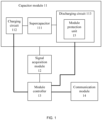
- FIG. 1 shows a structure of the power supply module according to some examples of the present disclosure.
- the power supply module may include: a capacitor module 11, a signal acquisition module 12, a module controller 13 and a communication module 14.
- the capacitor module 11 may include a supercapacitor 111, a charging circuit 112 and a discharging circuit 113.
- the charging circuit 112 may be connected with a charging power supply and may be configured to charge the supercapacitor 111.
- the discharging circuit 113 may be connected with a magnet via a bus and may be configured to discharge the magnet.
- the signal acquisition module 12 may be connected with the capacitor module 11 and may be configured to acquire a state signal of the capacitor module 11.
- the module controller 13 may be connected with the capacitor module 11 and the signal acquisition module 12 and may be configured to control a charging-discharging state of the capacitor module 11 and monitor the capacitor module 11 based on the state signal.
- the module controller 13 may adopt Raspberry Pi or MCU.
- the communication module 14 may be connected with the module controller 13 and may be configured to communicate with a module controller 13 in another power supply module or a main controller 20 in a power supply system.
- the state signal may include at least one of a current signal, a voltage signal, a trigger feedback signal of the charging circuit 112 and/or the discharging circuit 113, a real-time temperature of the supercapacitor 111, and a real-time temperature of a power device in the charging circuit 112 and/or the discharging circuit 113, and a communication state signal of the communication module and the like.
- the current signal may refer to a charging current of the charging circuit 112 and/or a discharging current of the discharging circuit 113 in a charging state or a discharging state obtained by a current sensor.
- a Hall current sensor shunt or an electromagnetic current transformer may be adopted as the current sensor.
- the voltage signal may refer to a voltage of the supercapacitor 111 obtained by a voltage sensor.
- the voltage signal may be the voltage of the supercapacitor 111 in an idle state.
- a current sensor may be adopted to obtain a current during a charging process or a discharging process, and then the voltage of the supercapacitor 111 may be calculated based on the current.
- the temperature signal may be obtained by a temperature sensor.
- the trigger feedback signal may be obtained by collecting a voltage or level change of a feedback circuit through the feedback circuit and a corresponding feedback terminal.
- a capacitor bank is formed by multiple capacitors in the form of an array as an energy storage element. Moreover, the capacitor bank is connected with an inverter to discharge a coil, where the inverter is configured to a switch and modulating a current waveform.
- conventional capacitor energy storages used as magnet driving power supplies are basically aluminum electrolytic capacitors. This kind of capacitor has a low energy density, resulting in a small energy storage of the power supply, making the discharging time be relatively short, and being unable to meet the requirements of continuous and slow discharge of the power supply during the discharging process of a fusion apparatus. Therefore, in the present disclosure, a supercapacitor with a higher energy density is adopted, to overcome the disadvantage of low energy storage of the electrolytic capacitor and discharge for a relative long time.
- each power supply module may have the charging circuit 112 that charges the supercapacitor 111 independently and the discharging circuit 113 that discharges the supercapacitor 111 independently. Further, each power supply module may be provided with an independent signal acquisition module 12 and an independent module controller 13. The signal acquisition module 12 may be used to acquire the state signal of the capacitor module 11. The module controller 13 may be used to control a charging-discharging state of the capacitor module 11 and monitor the capacitor module. In this case, each power supply module can operate independently.
- the power supply module in the present disclosure may be flexibly assembled according to a target voltage requirement and/or a target current requirement as a general module of the power supply system of the magnet in the magnetic confinement fusion apparatus. Moreover, a single power supply module may be maintained without affecting a normal operation of the power supply system of the magnet. In a case that the target voltage requirement and/or the target current requirement changes (i.e., the load changes), the number of the power supply modules connected in series and/or in parallel is just required to be adaptively adjusted according to a new target voltage requirement and/or a new target current requirement. In this way, a strong versatility and a relatively simple maintenance can be achieved.
- the module controller 13 in each power supply module may be configured to collect the state signal of the current power supply module from the corresponding signal acquisition module 12, and communicate with the main controller 20 through the communication module 14, so that the power supply system constructed by the multiple power supply modules may be analyzed in real time and an automatic alarm can be realized. In this way, any problem can be found immediately and located accurately. Furthermore, since each power supply module may be triggered independently and the operation condition thereof may be monitored independently, each power supply module can provide feedbacks independently, which provides a possibility of using carrier phase shift technology to modulate a total current waveform. Furthermore, by the multiple power supply modules connected in parallel, a current ripple can be minimized with a very high equivalent switching frequency.
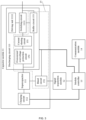
- FIG. 2 is a schematic diagram of a circuit principle of an exemplary power supply module according to some examples of the present disclosure. As shown in FIG. 2 , an operation principle of a power supply module can be described in detail with a diagram of a circuit principle of an exemplary power supply module.
- the capacitor module 11 may include a supercapacitor 111, a charging circuit 112 and a discharging circuit 113.
- the discharging circuit 113 may include: a switching circuit 1131 and a driving unit 1132 of the switching circuit 1131.
- the switching circuit 1131 may include a first control switch Q1 and a freewheel element.
- the driving unit 1132 is connected with a control end of the first control switch Q1.
- the first control switch Q1 and the freewheel element are connected in series with the supercapacitor 111.
- the freewheel element is connected with the magnet via the bus.
- the first control switch Q1 may adopt IGBT and MOS transistor.
- IGBT may be taken as an example in the present disclosure.
- a gate of the first control switch Q1 may be connected with the driving unit 1132 for opening and closing under a driving of the driving unit 1132.
- a collector of the first control switch Q1 may be connected with a positive electrode of the supercapacitor 111.
- An emitter of the first control switch Q1 may be connected with a positive electrode of the bus, and may be connected with a negative electrode of the freewheel element.
- a positive electrode of the freewheel element may be connected with a negative electrode of the bus and a negative electrode of the supercapacitor 111.
- the driving unit 1132 may control the first control switch Q1 to be turned on, so that the supercapacitor 111 may be connected to the bus and may be discharged to the magnet via the bus.
- the driving unit 1132 may control the first control switch Q1 to be turned off, so that the supercapacitor 111 may be not connected to the bus, and a freewheel circuit may be formed by the magnet, the bus and the freewheel element to discharge an electric quantity of the magnet.
- the freewheel element may adopt a freewheel diode.
- a positive electrode of the freewheel diode may be connected with the negative electrode of the supercapacitor 111 and the negative electrode of the bus.
- a negative electrode of the freewheel diode may be connected with the emitter of the first control switch Q1 and the positive electrode of the bus.
- the collector of the first control switch Q1 may be connected with the positive electrode of the supercapacitor 111.
- the freewheel element may further adopt IGBT. That is, a second control switch Q2 identical with the first control switch Q1 may be adopted. In this case, an emitter of the second control switch Q2 may be connected with the negative electrode of the supercapacitor 111 and the negative electrode of the bus. A collector of the second control switch Q2 may be connected with the emitter of the first control switch Q1 and the positive electrode of the bus. During the discharging process and the stop discharging process, the second control switch Q2 is always in an off state, and its diode connected in reverse parallel is used for performing freewheel.
- each power supply module may be further provided with an independent charging circuit 112.
- the charging circuit 112 may include a third control switch.
- a control end of the third control switch may be connected with the module controller 13.
- a first end of the third control switch may be connected with a charging power supply, and a second end may be connected with the supercapacitor 111.
- the module controller 13 of each power supply module can control the charging circuit 112 to charge the supercapacitor 111 independently.
- the charging power supply may be a low-voltage direct current power supply which may be connected with an external power supply, for example, with a 220V/380V/110V alternating current power supply, to convert a voltage of the external power supply into a voltage that may charge the supercapacitor 111.
- the charging power supply may include a rectifier circuit to convert an alternating current into a direct current voltage for charging the supercapacitor.
- the external power supply is a direct current power supply
- the charging power supply may adopt a direct current voltage conversion circuit, for example, a BUCK converter, a BUOOST converter or a Buck-Boost converter.
- the charging power supply may also be reused as a power supply powering for the module controller 13, the driving unit 1132 and the like that require a low-voltage direct current power supply.
- the external power supply may be converted to 15V and/or 24V direct current power supply to provide a low-voltage power supply required by the power supply module.
- FIG. 3 shows a structure of the power supply module according to another example of the present disclosure.
- each power supply module may further include a module protection unit 15.
- This module protection unit 15 may be provided in the discharging circuit 113, and may be configured to protect the power supply module.
- the module protection unit 15 can provide an independent protection function for the power supply module in an operation state or in a non-operation state, to disperse a risk of an overall power supply system to each single power supply module. In this way, even if the single power supply module has a malfunction, an influence of this power supply module on other power supply modules is relatively small since the single power supply module has the module protection unit 15 and can protect the power supply module independently. Moreover, since a voltage and current level of a single power supply module is relatively low, a violent energy caused by an accident can be reduced. In this way, the safety of the whole power supply system can be ensured.
- one supercapacitor 111 may have some differences with other supercapacitor 111.
- the charging states, electric quantities and discharging states of different supercapacitors 111 in different power supply modules may be inconsistent.
- the discharging currents of different power supply modules may be inconsistent too.
- the module protection unit 15 may include: a current sharing circuit 151 provided in the discharging circuit 113, and is configured to perform a current sharing process on discharging currents of supercapacitors 111 respectively in power supply modules of the power supply system in a case that the power supply system has multiple power supply modules.
- the current sharing module may share a discharging current of each power supply module in the power supply system to ensure current uniformity among the power supply modules connected in parallel.
- the current sharing circuit 151 may include a current sharing resistor R1, as shown in FIG. 2 .
- This current sharing resistor R1 may be connected in series with the output end of the supercapacitor 111, that is, connected in series between the supercapacitor 111 and a drain of the first control switch Q1. If an output current of the present power supply module is relatively high, a voltage drop on the current sharing may increase, so as to reduce the output current. In this case, a purpose of current sharing can be achieved.
- the current sharing circuit 151 may include a dynamic current sharing circuit.
- the dynamic current sharing circuit may be connected with the signal acquisition module 12 or the module controller 13.
- the dynamic current sharing circuit may adjust the voltage drop output by the current power supply module in real time based on the current output by the current power supply module, then adjust the current output by the current power supply module based on a difference between the current actually output by the current power supply module and the theoretical output current. In this way, the output current would be identical with the theoretical output current, and the purpose of current sharing would be achieved.
- the dynamic current sharing circuit may reuse the first control switch, and adjust the discharging current of the power supply module dynamically according to a duty ratio of the first control switch.
- the module controller may determine the duty ratio of the first control switch based on the real-time discharging current, and output a duty ratio control instruction to the driving unit, so that the driving unit may control the first control switch according to the corresponding duty ratio so as to dynamically adjust the discharging current in real time.
- the dynamic current sharing circuit may further include a fourth control switch connected in series in the discharging circuit.
- the module controller may determine a duty ratio of the fourth control switch based on the real-time discharging current after obtaining the real-time discharging current of the power supply module, so as to adjust the discharging current dynamically in real time.
- the module protection unit 15 may include: a bleed circuit 152.
- the bleed circuit is connected with the supercapacitor 111 and the module controller 13 and is configured to bleed an electric quantity of the supercapacitor 111 under triggering of the module controller 13.
- the bleed circuit 152 may include a bleed resistor and a bleed control unit.
- the bleed control unit may be connected with the module controller 13 for turning on or off the path between the bleed resistor and the supercapacitor 111 at the trigger of the module controller 13.
- the bleed resistor may adopt a water-cooled resistor having sufficient heat dissipation capacity in a case of bleeding a remaining power in the supercapacitor 111.
- the module controller 13 may control a corresponding bleed control unit to conduct a path between a corresponding bleed resistance and the supercapacitor 111 to discharge a residual energy on the supercapacitor 111.
- each power supply module has independent charging and bleeding control capabilities, which may not only improve the bleeding efficiency but also reduce the heat concentration problem during energy bleeding. Therefore, each power supply module functions as a power supply with a complete and independent discharging capability.
- multiple bleed circuits 152 may be provided for each power supply module.
- the module protection unit 15 may further include: a buffer circuit 153, connected in parallel in the discharging circuit 113, and is configured to buffer a spike pulse generated in a case that the discharging circuit 113 is turned off.
- the buffer circuit 153 may be connected in parallel between the supercapacitor 111 and the first control switch Q1.
- the buffer circuit 153 may include a first resistor R2, a first capacitor C1 and a first diode D1. One end of the first resistor R2 may be connected between a collector of the supercapacitor 111 and the first control switch Q1, while the other end may be connected with a positive electrode of the first capacitor C1.
- a negative electrode of the first capacitor C1 may be connected with a negative electrode of the supercapacitor 111 (the negative electrode of the bus).
- the first diode D1 may be connected in parallel with the first resistor R2.
- the negative electrode of the first diode D1 may be connected between the collector of the supercapacitor 111 and the collector of the first control switch Q1.
- the positive electrode of the first diode D1 may be connected with the positive electrode of the first capacitor C1.
- the buffer circuit 153 is configured to prevent the generation of a peak voltage.
- the current may charge the first capacitor C1 by the first diode D1 rapidly, so that the voltage at both ends of the bus can be controlled by the first capacitor C1.
- the first resistor R2 connected in parallel with the first diode D1 may consume the energy on the first capacitance C1, thereby preventing the circuit from oscillating.
- the buffer circuit 153 may be connected in parallel between the collector and the emitter of the first control switch Q1.
- the buffer circuit 153 may include: a second resistor R3, a second diode D2 and a second capacitor C2.
- One end of the second resistor R3 may be connected with the collector of the first control switch Q1, and the other end of the second resistor R3 may be connected with a positive electrode of the second capacitor C2.
- a negative electrode of the second capacitor C2 may be connected with a collector of the first control switch Q1.
- a negative electrode of the second diode D2 may be connected with the collector of the first control switch Q1, and a positive electrode of the second diode D2 may be connected with the positive electrode of the second capacitor C2.
- a buffering principle for the spike pulse generated in the circuit is identical with the function of the buffer circuit 153 in the example described above, which will not be repeated in the present example.
- the protection unit may further include an overcurrent/overvoltage protection circuit 154 provided in the discharging circuit 113 and configured to perform overcurrent/overvoltage protection on the discharging circuit.
- the overcurrent/overvoltage protection circuit 154 may include a fuse F1 connected in series at the output end of the supercapacitor 111 as an overcurrent protection device. In a case that the output current is too large, the fuse F1 may be turned off, thus the discharging circuit 113 of the current power supply module may be cut off.
- the overcurrent/overvoltage protection circuit 154 may further include: a varistor R4 connected in parallel at the output end of the power supply module.
- the varistor R4 can protect the supercapacitor 111 of the capacitor module 11 from overvoltage damaging in a case that the bus voltage is too high.
- FIG. 4 is a schematic diagram of the power supply system according to examples of the present disclosure.
- the power supply system may be constructed by multiple power supply modules described in the above examples.
- the power supply system may be formed by multiple power supply modules connected in series and/or in parallel with each other.
- the multiple power supply modules may be connected in series and/or in parallel with each other on the bus.
- the power supply system may further include: a main controller 20, which is in communication with the module controller 13 of each of the power supply modules via a communication module of the power supply module.
- the main controller 20 may be configured to receive state signals of the power supply modules and control an operation state of the power supply system based on the state signals.
- each power supply module may have a self-contained power supply with independent unit voltage and unit current output capabilities. After determining a target current requirement and a target voltage requirement of the magnet, the number of power supply modules connected in parallel may be determined by calculating a multiple relationship between the target current and the unit current. That is, the number of the multiple branches connected in parallel may be determined by calculating a multiple relationship between the target voltage and the unit voltage.
- the output unit voltage of the supercapacitor 111 in each power supply module is 129 V
- the output unit current is 1.2 KA
- the current required by the magnet in the magnetic confinement fusion apparatus is 110 KA. Therefore, 126 or more power supply modules should be connected in parallel to supply power to the magnet.
- the power supply system can output a highest current I peak >110KA, and a discharging duration is t>1s, which corresponds to a field strength B T >1T at a magnetic axis of the Tokamak.
- the main controller 20 may communicate with the module controller 13 of each power supply module respectively.
- the module controller 13 may obtain through its own signal acquisition module 12, a real-time current signal of a power supply module, a trigger state signal of the discharging circuit 113 and the like. These signals are uploaded to the main controller 20. Then, the main controller 20 monitors an operating state of each power supply module based on the operation state of each power supply module uploaded by each module controller 13.
- the module controller 13 Before discharging or in an idle state, the module controller 13 uploads state information such as the voltage and the temperature of the supercapacitor 111, the temperature of a switching circuit, a driving power supply state of the switching circuit acquired by the signal acquisition module to the main controller 20.
- the main controller 20 analyzes the state of the whole power supply system in real time, and an automatic alarm can be realized. In this way, any problems can be found immediately and located accurately.
- the power supply system may further include a clock synchronization module 30, connected with the multiple power supply modules, and configured to synchronize operation clocks of the multiple power supply modules.
- the discharging circuit 113 of each power supply module may be uniformly controlled by the main controller 20.
- the main controller 20 may be connected to the discharging circuit 113 of the power supply module.
- the main controller 20 is configured to output a discharging instruction or a stop discharging instruction to the discharging circuit 113, so as to control the discharging circuit 113 to discharge or stop discharging.
- the main controller 20 may be connected with the control end of the first control switch Q1 of the discharging circuit 113 respectively in each power supply module.
- the main controller 20 may output the discharging instruction, which controls the first control switches Q1 of all the power supply modules to be closed simultaneously. In this case, all the power supply modules would begin to discharge. In a case that discharging is required to be stopped, the main controller 20 may output the discharging stop instruction, which controls the first control switches Q1 of all the power supply modules to be turned off simultaneously to stop discharging.
- a first synchronization unit 31 may be provided between the main controller 20 and each power supply module to trigger the first control switches of all the power supply modules by a switch instruction simultaneously.
- the first synchronization unit 31 may synchronize the instruction to each power supply module after receiving the instruction sent by the main controller 20, so as to ensure that an operation action of each power supply module 10 is in a synchronous state.
- the first synchronization unit 31 may include a multi-paralleled optical fiber trigger.
- An input end of this optical fiber trigger may be connected with a switch instruction output end of the main controller 20.
- the optical fiber trigger may output a switch instruction synchronously to control the switch of each power supply module to be in a synchronous state.
- the optical fiber trigger can ensure that a switching delay is less than 1us, and a synchronization error between modules is less than 50ns, which may meet the demand of the multiple power supply modules discharging simultaneously in the power supply system.
- a second synchronization unit 32 may be further provided between each module controller 13.
- This second synchronization unit 32 may be connected with the module controllers 13 of the power supply modules, and is configured to synchronize clocks of the module controllers 13.
- the second synchronization unit 32 may synchronize the clocks of the remaining power supply modules by a Precision Timing Protocol (PTP), with the clock of one of the multiple power supply modules as a main clock.
- PTP Precision Timing Protocol
- the second synchronization unit 32 may further adopt a satellite clock synchronization system to synchronize the clock of each power supply module.
- the second synchronization unit 32 may further adopt another clock synchronization mode, such as the Network Time Protocol (NTP) and Time-Sensitive Networking (Time-Sensitive Networking, TNS), to synchronize the clock in each power supply module.
- NTP Network Time Protocol
- TNS Time-Sensitive Networking
- the main controller 20 may determine, based on the state signals, whether the supply modules are in a normal state to ensure that the power supply system can perform discharging normally. For example, the main controller 20 may detect the state of each power supply module respectively by collecting the state information of the power supply module uploaded by the module controller 13 of each power supply module. For example, the main controller 20 may detect the voltage and temperature of the supercapacitor 111 in each power supply module, the temperature of the first control switch Q1, and the power supply state of the driving unit of the first control switch Q1, and then determine whether the current power supply module has a discharging condition according to the state information of the power supply module.
- the current power supply module may be prohibited from discharging.
- the main controller 20 may further detect whether the communication state between each module controller and the main controller 20 is normal, and whether a remote control between the discharging circuit 113 of each power supply module and the main controller 20 is in an online state. In a case that the communication state is normal and the remote control is in an online state, it is confirmed that discharging is possible. Moreover, in a case that the communication state is abnormal or the remote control is in a disconnection state, the corresponding power supply module would be prohibited from discharging.
- the main controller 20 may further determine whether a pressure difference between each power supply module is greater than a preset pressure difference threshold based on the state signal of the power supply module. In a case that the pressure difference is greater than the preset pressure difference threshold, a voltage of the corresponding power supply module is detected. Moreover, in a case that the voltage is less than a preset voltage, a corresponding power supply module is prohibited from discharging to prevent another power supply module from overcharging the current power supply module.
- the power supply module without the discharging condition in a case that some power supply modules do not have a discharge condition, it may be determined whether the number of the power supply modules without the discharging condition is less than a preset number. In a case that the number is less than the preset number, it is confirmed that the discharging of the remaining power supply modules may meet the current and voltage requirement of the magnet, and therefore, the power supply module without the discharging condition may be shielded, and other power supply modules may discharge normally.
- the module controller of each power supply module may further control the first control switch Q1 in the discharging circuit 113 of the current power supply module individually. If the power supply module does not meet the discharging condition before discharging, and the number of the power supply modules without the discharging condition is less than the preset number, the main controller 20 sends an instruction to the module controller 13 to shield the corresponding power supply module from discharging, so that the module controller 13 may control the discharging circuit 113 and the charging circuit 112 to remain disconnected.
- a fourth control switch may be connected in series between the discharging circuit 113 in the power supply module and the main controller 20, and a control end of the fourth control switch may be connected with the module controller 13.
- the module controller 13 may control the fourth control switch to cut off the connection between the discharging circuit 113 and the main controller 20 in a case that the module controller 13 receives a shielding instruction from the main controller 20, so that the main controller 20 may disable the control of the current power supply module, and so that the discharging instruction sent by the main controller 20 may not trigger the first control switch Q1 in the discharging circuit 113 of the current power supply module, and the first control switch Q1 may remain turned off.
- the current backflow of another module to the current power supply module may be prevented. Even if some power supply modules do not have the discharging condition, the power supply system may still supply power to the magnet. Further, the power supply system may further protect the power supply without the discharging condition from current backflow or overcurrent and overvoltage damaging.
- each power supply module may have a supercapacitor, a charging circuit that may charge the supercapacitor independently and a discharging circuit that may discharge the supercapacitor independently.
- Each power supply module is further provided with an independent signal acquisition module and a module controller. By the signal acquisition module, a state signal of the capacitor module may be acquired. Further, independent control of the charging-discharging state of the capacitor module and independent monitoring of the capacitor module can be realized by the module controller. In this way, each power supply module can operate independently.
- the power supply module in the present example may be assembled flexibly according to a target electric quantity requirement and/or a target current requirement as a general module of the power supply system of the magnet in the magnetic confinement fusion apparatus. Then, a single power supply module may be maintained without affecting a normal operation of the power supply system of the magnet.
- the target electric quantity requirement and/or the target current requirement changes, the number of the power supply modules connected in series and/or in parallel is just required to be adaptively adjusted according to a new target voltage requirement and/or a new target current requirement. In this way, a strong versatility and a relatively simple maintenance can be achieved.
- each power supply module may further include a module protection unit.
- the module protection unit has an independent protection function for the power supply module in an operation state or in a non-operation state to disperse a risk of an overall power supply system to a single power supply module. Even if a single power supply module has a malfunction, an influence of this power supply module on other power supply modules is relatively small since the single power supply module has the module protection unit and can protect itself independently,. Moreover, since a voltage and a current level of a single power supply module is relatively low, a violent energy caused by an accident can be reduced. In this way, the safety of the whole power supply system can be ensured.
- a current sharing circuit can be provided in the discharging circuit.
- the current sharing circuit is configured to perform a current sharing process on discharging currents of supercapacitors in a case that the multiple power supply modules construct the power supply system.
- the current sharing module may share a discharging current of each power supply module in the power supply system to ensure a current uniformity among the power supply modules connected in parallel.
- the module protection unit may further include a bleed circuit, connected with the supercapacitor and the module controller and configured to bleed an electric quantity of the supercapacitor under triggering of the module controller.
- the module controller controls a corresponding bleed control unit to conduct a path between a corresponding bleed resistance and the supercapacitor to discharge a residual energy on the supercapacitor. It may not only improve a bleeding efficiency, but also reduce a heat concentration problem during energy bleeding.
- the single power supply module may have an independent charging-discharging control capability, so it may have a complete and independent discharging capability.
- a target current requirement and a target voltage requirement of the magnet may be satisfied adaptively by connecting multiple power supply modules in parallel and/or in series.
- the module controller of each of the power supply modules may obtain through its own signal acquisition module, a real-time current signal of a current power supply module, a trigger state signal of the discharging circuit 113 and the like. These signals are uploaded to the main controller. Then the main controller monitors an operating state of each power supply module based on the operation state of each power supply module uploaded by each module controller.
- the module controller Before discharging or in an idle state, the module controller uploads state information such as the voltage and the temperature of the supercapacitor, the temperature of a switching circuit, a driving power supply state of the switching circuit acquired by the signal acquisition module to the main controller.
- the main controller analyzes the state of the whole power supply system in real time, and an automatic alarm can be realized. In this way, any problem can be found immediately and located accurately.
- each power supply module may be uniformly controlled by the main controller.
- a first synchronization unit may be provided between the main controller and each power supply module. The first synchronization unit may synchronize the instruction to each power supply module after receiving the instruction sent by the main controller, so as to ensure that an operation action of each power supply module is in a synchronous state.
- a second synchronization unit may be further provided between each module controller.
- the second synchronization unit may be connected with the module controller, and is configured to synchronize clocks between the module controllers.
- a clock error between the module controllers may be ensured to be relatively small, so that the state signal uploaded by the module controller of each power supply module received by the main controller is synchronous.
Landscapes
- Engineering & Computer Science (AREA)
- Power Engineering (AREA)
- Physics & Mathematics (AREA)
- Plasma & Fusion (AREA)
- General Engineering & Computer Science (AREA)
- High Energy & Nuclear Physics (AREA)
- Charge And Discharge Circuits For Batteries Or The Like (AREA)
- Direct Current Feeding And Distribution (AREA)
Abstract
Description
- The present application claims priority to
Chinese Patent Application "202310825152.4", filed on July 06, 2023 - The present disclosure relates to the field of electronic power technology, and in particular, to a power supply module and a power supply system for driving a magnet in a magnetic confinement fusion apparatus.
- A fusion apparatus such as a tokamak apparatus controls a plasma by a magnetic field, and the magnetic field is generated by passing a certain current into a magnetic field coil. Therefore, a high-power pulsed power supply is generally required to inject current into the magnetic field coil, that is, a magnet driving power supply. Usually, the magnet driving power supply requires to be able to reach megawatt (MW) or even a higher level of power in a short period of time. If such a power demand is directly introduced from a power grid, a load requirement on the power grid is higher. Therefore, a large-capacity energy storage element is generally used in the existing magnet driving power supply. The large-capacity energy storage element first acquires energy from the power grid and stores the energy, and then feeds the energy into the magnetic field coil for a short period of time.
- In the existing magnet driving power supply, a flywheel generator is generally used to store energy. The flywheel generator can store a relatively large amount of energy. Moreover, the flywheel generator has high output power, meeting a power demand of various fusion apparatus such as the tokamak apparatus. However, a power supply system consisting of the flywheel generator is relatively complex and has poor versatility. Furthermore, if a malfunction occurs, the maintainability is poor.
- Therefore, how to meet a power supply demand of the fusion apparatus while improving suitability and maintenance of the magnet driving power supply has become an urgent technical problem.
- The present disclosure provides a power supply module and a power supply system used for driving a magnet in a magnetic confinement fusion apparatus. The power supply module and the power supply system may solve the technical problem of how to improve suitability and maintenance of a magnet driving power supply while meeting a power supply demand of a fusion apparatus in the related art.
- According to a first aspect, some examples of the present disclosure provide a power supply module. The power supply module includes: a capacitor module, a signal acquisition module, a module controller and a communication module. The capacitor module includes a supercapacitor, a charging circuit and a discharging circuit, where the charging circuit is connected with a charging power supply and is configured to charge the supercapacitor, and the discharging circuit is connected with a magnet in a magnetic confinement fusion apparatus via a bus and is configured to discharge the magnet. The signal acquisition module is connected with the capacitor module and is configured to acquire a state signal of the capacitor module. The module controller is connected with the capacitor module and the signal acquisition module, and the module controller is configured to control a charging-discharging state of the capacitor module and monitor the capacitor module based on the state signal. The communication module is connected with the module controller and is configured to communicate with a module controller in another power supply module or a main controller in a power supply system. The power supply system is formed by multiple power supply modules and is configured to supply power to the magnet.
- According to a second aspect, some other examples of the present disclosure provide a power supply system. The power supply system includes: multiple power supply modules disclosed and a main controller. The multiple power supply modules are connected to the bus to supply power to the magnet. The main controller is in communication with a module controller of each of the power supply modules via a communication module of the power supply module, and the main controller is configured to receive state signals of the power supply modules and control an operation state of the power supply system based on the state signals.
- In examples of the present disclosure, each power supply module may have a supercapacitor and a charging circuit that may charge the supercapacitor independently and a discharging circuit that may discharge the supercapacitor independently. Further, each power supply module may be provided with an independent signal acquisition module and a module controller. A state signal of the capacitor module can be obtained by the signal acquisition module. Moreover, independent control of the charging-discharging state of the capacitor module and independent monitoring of the capacitor module can be realized by the module controller. In this way, each power supply module can operate independently. Therefore, the power supply module in the present disclosure may be flexibly assembled according to a target electric quantity requirement and/or a target current requirement as a general module of the power supply system of the magnet in the magnetic confinement fusion apparatus. Then, a single power supply module may be maintained without affecting a normal operation of the power supply system of the magnet. In a case that the target electric quantity requirement and/or the target current requirement changes, the number of the power supply modules connected in series and/or in parallel is just required to be adaptively adjusted according to a new target electric quantity requirement and/or a new target current requirement. In this way, a strong versatility and a relatively simple maintenance can be achieved.
- The drawings herein are included in the specification and form a part of the present specification, show embodiments that comply with the present disclosure, and are used together with the specification for explaining the principles of the present disclosure.
- In order to describe technical solutions of the present disclosure or related arts more clearly, accompanying drawings required for describing examples or the related art are introduced briefly in the following. Apparently, the accompanying drawings in the following descriptions only illustrate some examples of the present disclosure, and those of ordinary skill in the art may still derive other drawings from these drawings without creative efforts.
-
FIG. 1 is a schematic diagram of an exemplary power supply module used for driving a magnet in a magnetic confinement fusion apparatus according to some examples of the present disclosure. -
FIG. 2 is a schematic diagram of a circuit principle of an exemplary power supply module used for driving a magnet in a magnetic confinement fusion apparatus according to some examples of the present disclosure. -
FIG. 3 is a schematic diagram of another exemplary power supply module used for driving a magnet in a magnetic confinement fusion apparatus according to some other examples of the present disclosure. -
FIG. 4 is a schematic diagram of an exemplary power supply system according to some examples of the present disclosure. - In order to enable those ordinary skilled in the art to better understand the scheme of the present disclosure, the technical scheme in examples of the present disclosure will be clearly and completely described in combination with drawings of the present disclosure. Obviously, the described examples are only part of the present disclosure, but not all the embodiments. Based on the examples disclosed, all other examples obtained by those ordinary skilled in the art without paying any creative efforts should fall within the scope of protection of the present disclosure.
- It should be noted that the terms "first", "second" and the like in the specification and claims and the drawings of the present disclosure are used for distinguishing similar objects, and not necessarily to describe a particular order or precedence. It should be understood that the data used in this way may be interchanged under appropriate circumstances so that the examples of the present disclosure described herein may be implemented in an order other than those illustrated or described herein. Furthermore, the terms "include/comprise" and "have" as well as any variants thereof, are intended to cover a non-exclusive inclusion, for example, containing a process, method, system, product or device of a series of steps or units which are not necessarily limited to the explicitly listed steps or units, but may include other steps or units not explicitly listed or inherent to such process, method, product or device.
- The present disclosure provides a power supply module. The power supply module provided is used for driving a magnet in a magnetic confinement fusion apparatus. In some examples of the present disclosure, the power supply module may adopt a modular design. Moreover, multiple power supply modules may be connected in series and/or in parallel with each other based on a target electric quantity requirement of the magnet, to form a power supply system used for driving the magnet, so as to power the magnet.
FIG. 1 shows a structure of the power supply module according to some examples of the present disclosure. As shown inFIG. 1 , the power supply module may include: acapacitor module 11, asignal acquisition module 12, amodule controller 13 and acommunication module 14. - According to these examples, the
capacitor module 11 may include asupercapacitor 111, acharging circuit 112 and adischarging circuit 113. Thecharging circuit 112 may be connected with a charging power supply and may be configured to charge thesupercapacitor 111. Thedischarging circuit 113 may be connected with a magnet via a bus and may be configured to discharge the magnet. - The
signal acquisition module 12 may be connected with thecapacitor module 11 and may be configured to acquire a state signal of thecapacitor module 11. - The
module controller 13 may be connected with thecapacitor module 11 and thesignal acquisition module 12 and may be configured to control a charging-discharging state of thecapacitor module 11 and monitor thecapacitor module 11 based on the state signal. In some examples, themodule controller 13 may adopt Raspberry Pi or MCU. - The
communication module 14 may be connected with themodule controller 13 and may be configured to communicate with amodule controller 13 in another power supply module or amain controller 20 in a power supply system. - As an exemplary example, the state signal may include at least one of a current signal, a voltage signal, a trigger feedback signal of the charging
circuit 112 and/or the dischargingcircuit 113, a real-time temperature of thesupercapacitor 111, and a real-time temperature of a power device in thecharging circuit 112 and/or the dischargingcircuit 113, and a communication state signal of the communication module and the like. - In examples of the present disclosure, the current signal may refer to a charging current of the charging
circuit 112 and/or a discharging current of the dischargingcircuit 113 in a charging state or a discharging state obtained by a current sensor. For example, a Hall current sensor shunt or an electromagnetic current transformer may be adopted as the current sensor. The voltage signal may refer to a voltage of thesupercapacitor 111 obtained by a voltage sensor. For example, the voltage signal may be the voltage of thesupercapacitor 111 in an idle state. In other examples, a current sensor may be adopted to obtain a current during a charging process or a discharging process, and then the voltage of thesupercapacitor 111 may be calculated based on the current. - In some other examples of the present disclosure, the temperature signal may be obtained by a temperature sensor. The trigger feedback signal may be obtained by collecting a voltage or level change of a feedback circuit through the feedback circuit and a corresponding feedback terminal.
- In a driving power supply of a magnet in some magnetic confinement fusion apparatus, there is a related technology of constructing a power supply system by adopting a capacitor energy storage mode. Specifically, a capacitor bank is formed by multiple capacitors in the form of an array as an energy storage element. Moreover, the capacitor bank is connected with an inverter to discharge a coil, where the inverter is configured to a switch and modulating a current waveform. However, conventional capacitor energy storages used as magnet driving power supplies are basically aluminum electrolytic capacitors. This kind of capacitor has a low energy density, resulting in a small energy storage of the power supply, making the discharging time be relatively short, and being unable to meet the requirements of continuous and slow discharge of the power supply during the discharging process of a fusion apparatus. Therefore, in the present disclosure, a supercapacitor with a higher energy density is adopted, to overcome the disadvantage of low energy storage of the electrolytic capacitor and discharge for a relative long time.
- In some examples, a load of the magnetic confinement fusion apparatus may change in practice. Therefore, in order to accommodate more loads and to make the power supply system more scalable and reliable in a case of powering the magnetic confinement fusion apparatus, besides the
supercapacitor 111, each power supply module may have the chargingcircuit 112 that charges thesupercapacitor 111 independently and the dischargingcircuit 113 that discharges thesupercapacitor 111 independently. Further, each power supply module may be provided with an independentsignal acquisition module 12 and anindependent module controller 13. Thesignal acquisition module 12 may be used to acquire the state signal of thecapacitor module 11. Themodule controller 13 may be used to control a charging-discharging state of thecapacitor module 11 and monitor the capacitor module. In this case, each power supply module can operate independently. Therefore, the power supply module in the present disclosure may be flexibly assembled according to a target voltage requirement and/or a target current requirement as a general module of the power supply system of the magnet in the magnetic confinement fusion apparatus. Moreover, a single power supply module may be maintained without affecting a normal operation of the power supply system of the magnet. In a case that the target voltage requirement and/or the target current requirement changes (i.e., the load changes), the number of the power supply modules connected in series and/or in parallel is just required to be adaptively adjusted according to a new target voltage requirement and/or a new target current requirement. In this way, a strong versatility and a relatively simple maintenance can be achieved. - In the present disclosure, the
module controller 13 in each power supply module may be configured to collect the state signal of the current power supply module from the correspondingsignal acquisition module 12, and communicate with themain controller 20 through thecommunication module 14, so that the power supply system constructed by the multiple power supply modules may be analyzed in real time and an automatic alarm can be realized. In this way, any problem can be found immediately and located accurately. Furthermore, since each power supply module may be triggered independently and the operation condition thereof may be monitored independently, each power supply module can provide feedbacks independently, which provides a possibility of using carrier phase shift technology to modulate a total current waveform. Furthermore, by the multiple power supply modules connected in parallel, a current ripple can be minimized with a very high equivalent switching frequency. -
FIG. 2 is a schematic diagram of a circuit principle of an exemplary power supply module according to some examples of the present disclosure. As shown inFIG. 2 , an operation principle of a power supply module can be described in detail with a diagram of a circuit principle of an exemplary power supply module. - The
capacitor module 11 may include asupercapacitor 111, a chargingcircuit 112 and a dischargingcircuit 113. The dischargingcircuit 113 may include: a switchingcircuit 1131 and adriving unit 1132 of theswitching circuit 1131. Theswitching circuit 1131 may include a first control switch Q1 and a freewheel element. Thedriving unit 1132 is connected with a control end of the first control switch Q1. The first control switch Q1 and the freewheel element are connected in series with thesupercapacitor 111. Moreover, the freewheel element is connected with the magnet via the bus. - In some exemplary examples, the first control switch Q1 may adopt IGBT and MOS transistor. In order to ensure a voltage level and a switching rate of a controllable switching device such as a relay, IGBT may be taken as an example in the present disclosure.
- A gate of the first control switch Q1 may be connected with the
driving unit 1132 for opening and closing under a driving of thedriving unit 1132. A collector of the first control switch Q1 may be connected with a positive electrode of thesupercapacitor 111. An emitter of the first control switch Q1 may be connected with a positive electrode of the bus, and may be connected with a negative electrode of the freewheel element. Moreover, a positive electrode of the freewheel element may be connected with a negative electrode of the bus and a negative electrode of thesupercapacitor 111. - Upon receiving a discharging instruction, the
driving unit 1132 may control the first control switch Q1 to be turned on, so that thesupercapacitor 111 may be connected to the bus and may be discharged to the magnet via the bus. Upon receiving a discharging stop instruction, thedriving unit 1132 may control the first control switch Q1 to be turned off, so that thesupercapacitor 111 may be not connected to the bus, and a freewheel circuit may be formed by the magnet, the bus and the freewheel element to discharge an electric quantity of the magnet. - In the present disclosure, the freewheel element may adopt a freewheel diode. A positive electrode of the freewheel diode may be connected with the negative electrode of the
supercapacitor 111 and the negative electrode of the bus. A negative electrode of the freewheel diode may be connected with the emitter of the first control switch Q1 and the positive electrode of the bus. Moreover, the collector of the first control switch Q1 may be connected with the positive electrode of thesupercapacitor 111. - In some examples, the freewheel element may further adopt IGBT. That is, a second control switch Q2 identical with the first control switch Q1 may be adopted. In this case, an emitter of the second control switch Q2 may be connected with the negative electrode of the
supercapacitor 111 and the negative electrode of the bus. A collector of the second control switch Q2 may be connected with the emitter of the first control switch Q1 and the positive electrode of the bus. During the discharging process and the stop discharging process, the second control switch Q2 is always in an off state, and its diode connected in reverse parallel is used for performing freewheel. - As an exemplary example, each power supply module may be further provided with an
independent charging circuit 112. The chargingcircuit 112 may include a third control switch. A control end of the third control switch may be connected with themodule controller 13. A first end of the third control switch may be connected with a charging power supply, and a second end may be connected with thesupercapacitor 111. In this example, themodule controller 13 of each power supply module can control the chargingcircuit 112 to charge thesupercapacitor 111 independently. - In the present example, the charging power supply may be a low-voltage direct current power supply which may be connected with an external power supply, for example, with a 220V/380V/110V alternating current power supply, to convert a voltage of the external power supply into a voltage that may charge the
supercapacitor 111. In the present example, the charging power supply may include a rectifier circuit to convert an alternating current into a direct current voltage for charging the supercapacitor. In a case that the external power supply is a direct current power supply, the charging power supply may adopt a direct current voltage conversion circuit, for example, a BUCK converter, a BUOOST converter or a Buck-Boost converter. - In some examples, the charging power supply may also be reused as a power supply powering for the
module controller 13, thedriving unit 1132 and the like that require a low-voltage direct current power supply. In the present example, the external power supply may be converted to 15V and/or 24V direct current power supply to provide a low-voltage power supply required by the power supply module. -
FIG. 3 shows a structure of the power supply module according to another example of the present disclosure. As an exemplary example, as shown inFIG. 2 andFIG. 3 , each power supply module may further include amodule protection unit 15. Thismodule protection unit 15 may be provided in the dischargingcircuit 113, and may be configured to protect the power supply module. - In the present example, the
module protection unit 15 can provide an independent protection function for the power supply module in an operation state or in a non-operation state, to disperse a risk of an overall power supply system to each single power supply module. In this way, even if the single power supply module has a malfunction, an influence of this power supply module on other power supply modules is relatively small since the single power supply module has themodule protection unit 15 and can protect the power supply module independently. Moreover, since a voltage and current level of a single power supply module is relatively low, a violent energy caused by an accident can be reduced. In this way, the safety of the whole power supply system can be ensured. - To be noted, one
supercapacitor 111 may have some differences withother supercapacitor 111. Moreover, in a case that multiple power supply modules construct a power supply system, the charging states, electric quantities and discharging states ofdifferent supercapacitors 111 in different power supply modules may be inconsistent. In this case, when the power supply system discharges, the discharging currents of different power supply modules may be inconsistent too. - In some examples, the
module protection unit 15 may include: acurrent sharing circuit 151 provided in the dischargingcircuit 113, and is configured to perform a current sharing process on discharging currents ofsupercapacitors 111 respectively in power supply modules of the power supply system in a case that the power supply system has multiple power supply modules. In the present example, the current sharing module may share a discharging current of each power supply module in the power supply system to ensure current uniformity among the power supply modules connected in parallel. - In some examples, the
current sharing circuit 151 may include a current sharing resistor R1, as shown inFIG. 2 . This current sharing resistor R1 may be connected in series with the output end of thesupercapacitor 111, that is, connected in series between thesupercapacitor 111 and a drain of the first control switch Q1. If an output current of the present power supply module is relatively high, a voltage drop on the current sharing may increase, so as to reduce the output current. In this case, a purpose of current sharing can be achieved. - In other examples, the
current sharing circuit 151 may include a dynamic current sharing circuit. The dynamic current sharing circuit may be connected with thesignal acquisition module 12 or themodule controller 13. The dynamic current sharing circuit may adjust the voltage drop output by the current power supply module in real time based on the current output by the current power supply module, then adjust the current output by the current power supply module based on a difference between the current actually output by the current power supply module and the theoretical output current. In this way, the output current would be identical with the theoretical output current, and the purpose of current sharing would be achieved. - In the present example, the dynamic current sharing circuit may reuse the first control switch, and adjust the discharging current of the power supply module dynamically according to a duty ratio of the first control switch. In the present example, after obtaining the real-time discharging current of the power supply module, the module controller may determine the duty ratio of the first control switch based on the real-time discharging current, and output a duty ratio control instruction to the driving unit, so that the driving unit may control the first control switch according to the corresponding duty ratio so as to dynamically adjust the discharging current in real time.
- In other examples, the dynamic current sharing circuit may further include a fourth control switch connected in series in the discharging circuit. In this example, the module controller may determine a duty ratio of the fourth control switch based on the real-time discharging current after obtaining the real-time discharging current of the power supply module, so as to adjust the discharging current dynamically in real time.
- As an exemplary example, the
module protection unit 15 may include: ableed circuit 152. The bleed circuit is connected with thesupercapacitor 111 and themodule controller 13 and is configured to bleed an electric quantity of thesupercapacitor 111 under triggering of themodule controller 13. - For example, the
bleed circuit 152 may include a bleed resistor and a bleed control unit. The bleed control unit may be connected with themodule controller 13 for turning on or off the path between the bleed resistor and thesupercapacitor 111 at the trigger of themodule controller 13. In the present example, the bleed resistor may adopt a water-cooled resistor having sufficient heat dissipation capacity in a case of bleeding a remaining power in thesupercapacitor 111. - In the present example, after an operation of the power supply system, the
module controller 13 may control a corresponding bleed control unit to conduct a path between a corresponding bleed resistance and thesupercapacitor 111 to discharge a residual energy on thesupercapacitor 111. In this case, each power supply module has independent charging and bleeding control capabilities, which may not only improve the bleeding efficiency but also reduce the heat concentration problem during energy bleeding. Therefore, each power supply module functions as a power supply with a complete and independent discharging capability. - As an exemplary example, in order to ensure that a remaining energy in the
supercapacitor 111 may be safely and promptly bled once an accident occurs,multiple bleed circuits 152 may be provided for each power supply module. - As an exemplary example, the
module protection unit 15 may further include: abuffer circuit 153, connected in parallel in the dischargingcircuit 113, and is configured to buffer a spike pulse generated in a case that the dischargingcircuit 113 is turned off. For example, thebuffer circuit 153 may be connected in parallel between thesupercapacitor 111 and the first control switch Q1. Thebuffer circuit 153 may include a first resistor R2, a first capacitor C1 and a first diode D1. One end of the first resistor R2 may be connected between a collector of thesupercapacitor 111 and the first control switch Q1, while the other end may be connected with a positive electrode of the first capacitor C1. A negative electrode of the first capacitor C1 may be connected with a negative electrode of the supercapacitor 111 (the negative electrode of the bus). The first diode D1 may be connected in parallel with the first resistor R2. The negative electrode of the first diode D1 may be connected between the collector of thesupercapacitor 111 and the collector of the first control switch Q1. The positive electrode of the first diode D1 may be connected with the positive electrode of the first capacitor C1. - Since the bus from the
supercapacitor 111 to the first control switch Q1 has a relatively large distributed inductance, a relatively large peak voltage may be generated on the bus after the first control switch Q1 being turned off, which may cause an overvoltage damage to another element. In this example, thebuffer circuit 153 is configured to prevent the generation of a peak voltage. In a case that the first control switch is turned off, the current may charge the first capacitor C1 by the first diode D1 rapidly, so that the voltage at both ends of the bus can be controlled by the first capacitor C1. Moreover, the first resistor R2 connected in parallel with the first diode D1 may consume the energy on the first capacitance C1, thereby preventing the circuit from oscillating. - As an exemplary example, the
buffer circuit 153 may be connected in parallel between the collector and the emitter of the first control switch Q1. In this case, thebuffer circuit 153 may include: a second resistor R3, a second diode D2 and a second capacitor C2. One end of the second resistor R3 may be connected with the collector of the first control switch Q1, and the other end of the second resistor R3 may be connected with a positive electrode of the second capacitor C2. A negative electrode of the second capacitor C2 may be connected with a collector of the first control switch Q1. A negative electrode of the second diode D2 may be connected with the collector of the first control switch Q1, and a positive electrode of the second diode D2 may be connected with the positive electrode of the second capacitor C2. In a case that the first control switch Q1 is turned off, a buffering principle for the spike pulse generated in the circuit is identical with the function of thebuffer circuit 153 in the example described above, which will not be repeated in the present example. - As an exemplary example, the protection unit may further include an overcurrent/
overvoltage protection circuit 154 provided in the dischargingcircuit 113 and configured to perform overcurrent/overvoltage protection on the discharging circuit. In the present example, the overcurrent/overvoltage protection circuit 154 may include a fuse F1 connected in series at the output end of thesupercapacitor 111 as an overcurrent protection device. In a case that the output current is too large, the fuse F1 may be turned off, thus the dischargingcircuit 113 of the current power supply module may be cut off. - The overcurrent/
overvoltage protection circuit 154 may further include: a varistor R4 connected in parallel at the output end of the power supply module. The varistor R4 can protect thesupercapacitor 111 of thecapacitor module 11 from overvoltage damaging in a case that the bus voltage is too high. - Based on the power supply module, examples of the present disclosure further provide a power supply system.
FIG. 4 is a schematic diagram of the power supply system according to examples of the present disclosure. As shown inFIG. 4 , the power supply system may be constructed by multiple power supply modules described in the above examples. Specifically, the power supply system may be formed by multiple power supply modules connected in series and/or in parallel with each other. In the present example, the multiple power supply modules may be connected in series and/or in parallel with each other on the bus. - As shown in
FIG. 4 , the power supply system may further include: amain controller 20, which is in communication with themodule controller 13 of each of the power supply modules via a communication module of the power supply module. Themain controller 20 may be configured to receive state signals of the power supply modules and control an operation state of the power supply system based on the state signals. - In the present example, each power supply module may have a self-contained power supply with independent unit voltage and unit current output capabilities. After determining a target current requirement and a target voltage requirement of the magnet, the number of power supply modules connected in parallel may be determined by calculating a multiple relationship between the target current and the unit current. That is, the number of the multiple branches connected in parallel may be determined by calculating a multiple relationship between the target voltage and the unit voltage.
- For example, the output unit voltage of the
supercapacitor 111 in each power supply module is 129 V, the output unit current is 1.2 KA, and the current required by the magnet in the magnetic confinement fusion apparatus is 110 KA. Therefore, 126 or more power supply modules should be connected in parallel to supply power to the magnet. Under a condition that an internal resistance of the magnet is R=0.93, and a self-inductance L=590uH, the power supply system can output a highest current Ipeak>110KA, and a discharging duration is t>1s, which corresponds to a field strength BT>1T at a magnetic axis of the Tokamak. - Therefore, a target current requirement and a target voltage requirement of the magnet may be satisfied adaptively by connecting the multiple power supply modules in parallel and/or in series. The
main controller 20 may communicate with themodule controller 13 of each power supply module respectively. During the discharging process, themodule controller 13 may obtain through its ownsignal acquisition module 12, a real-time current signal of a power supply module, a trigger state signal of the dischargingcircuit 113 and the like. These signals are uploaded to themain controller 20. Then, themain controller 20 monitors an operating state of each power supply module based on the operation state of each power supply module uploaded by eachmodule controller 13. Before discharging or in an idle state, themodule controller 13 uploads state information such as the voltage and the temperature of thesupercapacitor 111, the temperature of a switching circuit, a driving power supply state of the switching circuit acquired by the signal acquisition module to themain controller 20. Themain controller 20 analyzes the state of the whole power supply system in real time, and an automatic alarm can be realized. In this way, any problems can be found immediately and located accurately. - As an exemplary example, in order to ensure that an operation state of each power supply module is synchronized, the power supply system may further include a
clock synchronization module 30, connected with the multiple power supply modules, and configured to synchronize operation clocks of the multiple power supply modules. - As an exemplary example, since the power supply system is constructed by connecting multiple power supply modules in parallel and/or in series, and the multiple power supply modules discharge the magnet as a whole, the discharging
circuit 113 of each power supply module may be uniformly controlled by themain controller 20. For example, themain controller 20 may be connected to the dischargingcircuit 113 of the power supply module. Themain controller 20 is configured to output a discharging instruction or a stop discharging instruction to the dischargingcircuit 113, so as to control the dischargingcircuit 113 to discharge or stop discharging. Specifically, themain controller 20 may be connected with the control end of the first control switch Q1 of the dischargingcircuit 113 respectively in each power supply module. In a case that discharging is required, themain controller 20 may output the discharging instruction, which controls the first control switches Q1 of all the power supply modules to be closed simultaneously. In this case, all the power supply modules would begin to discharge. In a case that discharging is required to be stopped, themain controller 20 may output the discharging stop instruction, which controls the first control switches Q1 of all the power supply modules to be turned off simultaneously to stop discharging. - In the present example, a
first synchronization unit 31 may be provided between themain controller 20 and each power supply module to trigger the first control switches of all the power supply modules by a switch instruction simultaneously. Thefirst synchronization unit 31 may synchronize the instruction to each power supply module after receiving the instruction sent by themain controller 20, so as to ensure that an operation action of eachpower supply module 10 is in a synchronous state. - In some examples, as shown in
FIG. 4 , thefirst synchronization unit 31 may include a multi-paralleled optical fiber trigger. An input end of this optical fiber trigger may be connected with a switch instruction output end of themain controller 20. The optical fiber trigger may output a switch instruction synchronously to control the switch of each power supply module to be in a synchronous state. In the present example, the optical fiber trigger can ensure that a switching delay is less than 1us, and a synchronization error between modules is less than 50ns, which may meet the demand of the multiple power supply modules discharging simultaneously in the power supply system. - In some other examples, in a case that the
main controller 20 determines the state of each power supply module, the state information of each power supply module are required to be synchronized. Therefore, a second synchronization unit 32 may be further provided between eachmodule controller 13. This second synchronization unit 32 may be connected with themodule controllers 13 of the power supply modules, and is configured to synchronize clocks of themodule controllers 13. As an exemplary example, the second synchronization unit 32 may synchronize the clocks of the remaining power supply modules by a Precision Timing Protocol (PTP), with the clock of one of the multiple power supply modules as a main clock. - In addition, the second synchronization unit 32 may further adopt a satellite clock synchronization system to synchronize the clock of each power supply module. In the present example, the second synchronization unit 32 may further adopt another clock synchronization mode, such as the Network Time Protocol (NTP) and Time-Sensitive Networking (Time-Sensitive Networking, TNS), to synchronize the clock in each power supply module.
- As an exemplary example, before discharging, the
main controller 20 may determine, based on the state signals, whether the supply modules are in a normal state to ensure that the power supply system can perform discharging normally. For example, themain controller 20 may detect the state of each power supply module respectively by collecting the state information of the power supply module uploaded by themodule controller 13 of each power supply module. For example, themain controller 20 may detect the voltage and temperature of thesupercapacitor 111 in each power supply module, the temperature of the first control switch Q1, and the power supply state of the driving unit of the first control switch Q1, and then determine whether the current power supply module has a discharging condition according to the state information of the power supply module. If the voltage of thesupercapacitor 111 is less than the preset voltage value, the temperature of thesupercapacitor 111 exceeds the first preset temperature value, the temperature of the first control switch Q1 exceeds the second preset temperature value, and a driving power supply state of the first control switch Q1 is not powered, it may lead to discharge failure. Therefore, the current power supply module may be prohibited from discharging. - In another example, before discharging, the
main controller 20 may further detect whether the communication state between each module controller and themain controller 20 is normal, and whether a remote control between the dischargingcircuit 113 of each power supply module and themain controller 20 is in an online state. In a case that the communication state is normal and the remote control is in an online state, it is confirmed that discharging is possible. Moreover, in a case that the communication state is abnormal or the remote control is in a disconnection state, the corresponding power supply module would be prohibited from discharging. - Since the power supply system is constructed by multiple power supply modules, if the voltage of one or several power supply modules in the power supply system is relatively small, or the
supercapacitor 111 is not charged, current backflow may occur during discharging. In another example, themain controller 20 may further determine whether a pressure difference between each power supply module is greater than a preset pressure difference threshold based on the state signal of the power supply module. In a case that the pressure difference is greater than the preset pressure difference threshold, a voltage of the corresponding power supply module is detected. Moreover, in a case that the voltage is less than a preset voltage, a corresponding power supply module is prohibited from discharging to prevent another power supply module from overcharging the current power supply module. - In order to reduce a shutdown frequency of the power supply system, in the present example, in a case that some power supply modules do not have a discharge condition, it may be determined whether the number of the power supply modules without the discharging condition is less than a preset number. In a case that the number is less than the preset number, it is confirmed that the discharging of the remaining power supply modules may meet the current and voltage requirement of the magnet, and therefore, the power supply module without the discharging condition may be shielded, and other power supply modules may discharge normally.
- In the present example, the module controller of each power supply module may further control the first control switch Q1 in the discharging
circuit 113 of the current power supply module individually. If the power supply module does not meet the discharging condition before discharging, and the number of the power supply modules without the discharging condition is less than the preset number, themain controller 20 sends an instruction to themodule controller 13 to shield the corresponding power supply module from discharging, so that themodule controller 13 may control the dischargingcircuit 113 and the chargingcircuit 112 to remain disconnected. - As an exemplary example, a fourth control switch may be connected in series between the discharging
circuit 113 in the power supply module and themain controller 20, and a control end of the fourth control switch may be connected with themodule controller 13. Themodule controller 13 may control the fourth control switch to cut off the connection between the dischargingcircuit 113 and themain controller 20 in a case that themodule controller 13 receives a shielding instruction from themain controller 20, so that themain controller 20 may disable the control of the current power supply module, and so that the discharging instruction sent by themain controller 20 may not trigger the first control switch Q1 in the dischargingcircuit 113 of the current power supply module, and the first control switch Q1 may remain turned off. Under the condition that the power supply system meets the power requirement of the magnet, the current backflow of another module to the current power supply module may be prevented. Even if some power supply modules do not have the discharging condition, the power supply system may still supply power to the magnet. Further, the power supply system may further protect the power supply without the discharging condition from current backflow or overcurrent and overvoltage damaging. - Therefore, it may be seen that in examples of the present disclosure, each power supply module may have a supercapacitor, a charging circuit that may charge the supercapacitor independently and a discharging circuit that may discharge the supercapacitor independently. Each power supply module is further provided with an independent signal acquisition module and a module controller. By the signal acquisition module, a state signal of the capacitor module may be acquired. Further, independent control of the charging-discharging state of the capacitor module and independent monitoring of the capacitor module can be realized by the module controller. In this way, each power supply module can operate independently. Therefore, the power supply module in the present example may be assembled flexibly according to a target electric quantity requirement and/or a target current requirement as a general module of the power supply system of the magnet in the magnetic confinement fusion apparatus. Then, a single power supply module may be maintained without affecting a normal operation of the power supply system of the magnet. In a case that the target electric quantity requirement and/or the target current requirement changes, the number of the power supply modules connected in series and/or in parallel is just required to be adaptively adjusted according to a new target voltage requirement and/or a new target current requirement. In this way, a strong versatility and a relatively simple maintenance can be achieved.
- Further, each power supply module may further include a module protection unit. The module protection unit has an independent protection function for the power supply module in an operation state or in a non-operation state to disperse a risk of an overall power supply system to a single power supply module. Even if a single power supply module has a malfunction, an influence of this power supply module on other power supply modules is relatively small since the single power supply module has the module protection unit and can protect itself independently,. Moreover, since a voltage and a current level of a single power supply module is relatively low, a violent energy caused by an accident can be reduced. In this way, the safety of the whole power supply system can be ensured.
- Further, a current sharing circuit can be provided in the discharging circuit. The current sharing circuit is configured to perform a current sharing process on discharging currents of supercapacitors in a case that the multiple power supply modules construct the power supply system. The current sharing module may share a discharging current of each power supply module in the power supply system to ensure a current uniformity among the power supply modules connected in parallel.
- Further, the module protection unit may further include a bleed circuit, connected with the supercapacitor and the module controller and configured to bleed an electric quantity of the supercapacitor under triggering of the module controller. After the power supply system finishing operating, the module controller controls a corresponding bleed control unit to conduct a path between a corresponding bleed resistance and the supercapacitor to discharge a residual energy on the supercapacitor. It may not only improve a bleeding efficiency, but also reduce a heat concentration problem during energy bleeding. Moreover, the single power supply module may have an independent charging-discharging control capability, so it may have a complete and independent discharging capability.
- Further, a target current requirement and a target voltage requirement of the magnet may be satisfied adaptively by connecting multiple power supply modules in parallel and/or in series. During a discharging process, the module controller of each of the power supply modules may obtain through its own signal acquisition module, a real-time current signal of a current power supply module, a trigger state signal of the discharging
circuit 113 and the like. These signals are uploaded to the main controller. Then the main controller monitors an operating state of each power supply module based on the operation state of each power supply module uploaded by each module controller. Before discharging or in an idle state, the module controller uploads state information such as the voltage and the temperature of the supercapacitor, the temperature of a switching circuit, a driving power supply state of the switching circuit acquired by the signal acquisition module to the main controller. The main controller analyzes the state of the whole power supply system in real time, and an automatic alarm can be realized. In this way, any problem can be found immediately and located accurately. - Further, the discharging circuit of each power supply module may be uniformly controlled by the main controller. In order to trigger the first control switches of all the power supply modules by a switch instruction simultaneously, a first synchronization unit may be provided between the main controller and each power supply module. The first synchronization unit may synchronize the instruction to each power supply module after receiving the instruction sent by the main controller, so as to ensure that an operation action of each power supply module is in a synchronous state.
- Further, a second synchronization unit may be further provided between each module controller. The second synchronization unit may be connected with the module controller, and is configured to synchronize clocks between the module controllers. By the second synchronization unit, a clock error between the module controllers may be ensured to be relatively small, so that the state signal uploaded by the module controller of each power supply module received by the main controller is synchronous.
- The above are only preferred examples of the present disclosure. It should be noted that, for those ordinary skilled in the art, a number of improvements and modifications may be made without departing from the principles of the present disclosure, and these improvements and modifications shall be construed as being included in the protection scope of the present disclosure.
Claims (14)
- A power supply module, comprising:a capacitor module, comprising a supercapacitor, a charging circuit and a discharging circuit; wherein, the charging circuit is connected with a charging power supply and is configured to charge the supercapacitor, and the discharging circuit is connected with a magnet in a magnetic confinement fusion apparatus via a bus and is configured to discharge the magnet;a signal acquisition module, connected with the capacitor module and configured to acquire a state signal of the capacitor module;a module controller, connected with the capacitor module and the signal acquisition module and configured to control a charging-discharging state of the capacitor module and monitor the capacitor module based on the state signal; anda communication module, connected with the module controller and configured to communicate with a module controller in another power supply module or a main controller in a power supply system, wherein the power supply system is formed by a plurality of power supply modules and is configured to supply power to the magnet.
- The power supply module according to claim 1, further comprising:
a module protection unit, provided in the discharging circuit and configured to protect the power supply module. - The power supply module according to claim 2, wherein the module protection unit comprises at least one of:a current sharing circuit, configured to perform a current sharing process on discharging currents of supercapacitors respectively in power supply modules of the power supply system;a bleed circuit, connected with the supercapacitor and the module controller and configured to bleed an electric quantity of the supercapacitor under triggering of the module controller;a buffer circuit, configured to buffer a spike pulse generated in a case that the discharging circuit is turned off; andan overcurrent/overvoltage protection circuit, configured to perform an overcurrent/overvoltage protection on the discharging circuit.
- The power supply module according to claim 1, wherein the discharging circuit comprises: a first control switch, a freewheel element and a driving unit;the driving unit is connected with a control end of the first control switch;the first control switch and the freewheel element are connected in series with the supercapacitor; andthe freewheel element is connected with the magnet via the bus.
- The power supply module according to claim 4, whereinupon receiving a discharging instruction, the driving unit controls the first control switch to be turned on, so that the supercapacitor is connected to the bus and is discharged to the magnet via the bus; andupon receiving a discharging stop instruction, the driving unit controls the first control switch to be turned off, so that the supercapacitor is not connected to the bus, and a freewheel circuit is formed by the magnet, the bus and the freewheel element to discharge an electric quantity of the magnet.
- The power supply module according to claim 4, wherein the freewheel element comprises a second control switch, wherein the second control switch is connected in series with the first control switch, and a control end of the second control switch is connected with an output end of the driving unit.
- The power supply module according to claim 1, wherein the power supply system is formed by the plurality of the power supply modules connected in series and/or in parallel with each other based on a target electric quantity requirement of the magnet.
- A power supply system, comprising:a plurality of power supply modules according to any one of claims 1 to 7, wherein the plurality of power supply modules are connected to the bus to supply power to the magnet; anda main controller, which is in communication with a module controller of each of the power supply modules via a communication module of the power supply module, and the main controller is configured to receive state signals of the power supply modules and control an operation state of the power supply system based on the state signals.
- The power supply system according to claim 8, further comprising:
a clock synchronization module, connected with the plurality of power supply modules, and configured to synchronize operation clocks of the plurality of power supply modules. - The power supply system according to claim 9, whereinfor each of the power supply modules, the main controller is connected with the discharging circuit of the power supply module and is configured to output a discharging instruction or a discharging stop instruction to the discharging circuit to control the discharging circuit to discharge or stop discharging; andthe clock synchronization module comprises a first synchronization unit connected between the main controller and the discharging circuit, and the first synchronization unit is configured to synchronize the discharging instruction or the discharging stop instruction to the discharging circuit.
- The power supply system according to claim 9, wherein the clock synchronization module further comprises a second synchronization unit; and
the second synchronization unit is connected with module controllers of the power supply modules, and is configured to synchronize clocks of the module controllers. - The power supply system according to claim 8, wherein the main controller is further configured to:determine, based on the state signals, whether the power supply modules are in a normal state before outputting a discharging instruction; andoutput the discharging instruction in a case that the power supply modules are in the normal state.
- The power supply system according to claim 12, wherein in a case that at least one of the power supply modules is in an abnormal state, the main controller or the module controller shields the power supply module in the abnormal state.
- The power supply system according to claim 8, wherein the plurality of power supply modules are connected in series and/or in parallel with each other on the bus.
Applications Claiming Priority (2)
| Application Number | Priority Date | Filing Date | Title |
|---|---|---|---|
| CN202310825152.4A CN119275954A (en) | 2023-07-06 | 2023-07-06 | Power module and power system for driving magnets in magnetic confinement fusion device |
| PCT/CN2024/072886 WO2025007544A1 (en) | 2023-07-06 | 2024-01-17 | Power supply module and power supply system |
Publications (2)
| Publication Number | Publication Date |
|---|---|
| EP4518093A1 true EP4518093A1 (en) | 2025-03-05 |
| EP4518093A4 EP4518093A4 (en) | 2025-08-13 |
Family
ID=90720035
Family Applications (1)
| Application Number | Title | Priority Date | Filing Date |
|---|---|---|---|
| EP24712394.6A Pending EP4518093A4 (en) | 2023-07-06 | 2024-01-17 | POWER SUPPLY MODULE AND POWER SUPPLY SYSTEM |
Country Status (4)
| Country | Link |
|---|---|
| US (1) | US20250232886A1 (en) |
| EP (1) | EP4518093A4 (en) |
| CN (1) | CN119275954A (en) |
| WO (1) | WO2025007544A1 (en) |
Family Cites Families (8)
| Publication number | Priority date | Publication date | Assignee | Title |
|---|---|---|---|---|
| EP2437386A1 (en) * | 2010-10-04 | 2012-04-04 | PL Technologies AG | Stabilized high-voltage power supply |
| GB2542789A (en) * | 2015-09-29 | 2017-04-05 | Alstom Technology Ltd | Fault protection for voltage source converters |
| EA202090027A1 (en) * | 2017-06-12 | 2020-04-03 | Таэ Текнолоджиз, Инк. | MULTILEVEL MULTI QUADRANT HYSTERESIS CURRENT CONTROLLERS AND METHODS OF MANAGING THEM |
| CN110460153B (en) * | 2019-07-23 | 2021-03-09 | 清华大学 | Multiport electric energy router control system |
| WO2021211630A2 (en) * | 2020-04-14 | 2021-10-21 | Tae Technologies, Inc. | Systems, devices, and methods for charging and discharging module-based cascaded energy systems |
| CN114629221A (en) * | 2022-03-03 | 2022-06-14 | 中国科学院合肥物质科学研究院 | Super capacitor charge and discharge control circuit and method suitable for magnetic confinement device |
| CN114844074A (en) * | 2022-06-10 | 2022-08-02 | 上海奥威科技开发有限公司 | Energy storage system and control method thereof |
| CN116317487A (en) * | 2023-03-02 | 2023-06-23 | 核工业西南物理研究院 | A Power Unit Controller Based on a New Energy Storage Pulse Power Supply |
-
2023
- 2023-07-06 CN CN202310825152.4A patent/CN119275954A/en active Pending
-
2024
- 2024-01-17 US US18/703,693 patent/US20250232886A1/en active Pending
- 2024-01-17 EP EP24712394.6A patent/EP4518093A4/en active Pending
- 2024-01-17 WO PCT/CN2024/072886 patent/WO2025007544A1/en not_active Ceased
Also Published As
| Publication number | Publication date |
|---|---|
| CN119275954A (en) | 2025-01-07 |
| US20250232886A1 (en) | 2025-07-17 |
| EP4518093A4 (en) | 2025-08-13 |
| WO2025007544A1 (en) | 2025-01-09 |
Similar Documents
| Publication | Publication Date | Title |
|---|---|---|
| US20190072070A1 (en) | Control system for enhancing frequency support of wind turbine generator | |
| US12136848B2 (en) | Battery assembly and energy storage system | |
| CN102148529B (en) | Control device and control method thereof for intelligently supplying power to circuit breaker control unit | |
| CN105514935A (en) | Undervoltage controller having time delay function and control method thereof | |
| CN102005772A (en) | Network combination inversion system and control method thereof | |
| CN201994717U (en) | Control device for supplying power to breaker control units | |
| CN209016720U (en) | A kind of novel power cell | |
| CA3136856C (en) | Control signal modulation circuit, inverter, and control system | |
| US20250232886A1 (en) | Power supply module and power supply system | |
| CN120824902A (en) | A dual power supply system with built-in battery in a high-voltage box and a control method thereof | |
| US20250141252A1 (en) | Energy storage converter, and energy storage system | |
| CN120414459A (en) | Power supply architecture, electronic equipment, management method, device, medium and program product | |
| CN114400751A (en) | Battery group parallel system, control method and storage medium | |
| CN120341988A (en) | A photovoltaic storage integrated system and control method | |
| CN113514762A (en) | System for detecting state of APF/SVG relay | |
| CN107749664B (en) | Design circuit of acquisition system emergency power supply | |
| CN111864735B (en) | A switching compensation system | |
| CN115589060A (en) | A DC system backup device for a station | |
| CN115313686A (en) | Repetition frequency pulse magnetic field device with positive and negative charge and discharge | |
| CN219107111U (en) | Battery group parallel device | |
| CN213093920U (en) | Intelligent power supply system for elevator | |
| CN219304695U (en) | Intelligent electric-dazzling protection device of frequency converter type | |
| CN221225374U (en) | Airborne bus bar control system and flight device | |
| CN119891708B (en) | Driving energy taking system and driving energy taking method of power semiconductor device | |
| CN220629190U (en) | High-power density power supply system |
Legal Events
| Date | Code | Title | Description |
|---|---|---|---|
| STAA | Information on the status of an ep patent application or granted ep patent |
Free format text: STATUS: UNKNOWN |
|
| STAA | Information on the status of an ep patent application or granted ep patent |
Free format text: STATUS: THE INTERNATIONAL PUBLICATION HAS BEEN MADE |
|
| PUAI | Public reference made under article 153(3) epc to a published international application that has entered the european phase |
Free format text: ORIGINAL CODE: 0009012 |
|
| STAA | Information on the status of an ep patent application or granted ep patent |
Free format text: STATUS: REQUEST FOR EXAMINATION WAS MADE |
|
| 17P | Request for examination filed |
Effective date: 20240327 |
|
| AK | Designated contracting states |
Kind code of ref document: A1 Designated state(s): AL AT BE BG CH CY CZ DE DK EE ES FI FR GB GR HR HU IE IS IT LI LT LU LV MC ME MK MT NL NO PL PT RO RS SE SI SK SM TR |
|
| A4 | Supplementary search report drawn up and despatched |
Effective date: 20250711 |
|
| RIC1 | Information provided on ipc code assigned before grant |
Ipc: H02J 7/00 20060101AFI20250707BHEP Ipc: H02J 7/34 20060101ALI20250707BHEP |
|
| RAP3 | Party data changed (applicant data changed or rights of an application transferred) |
Owner name: SHANGHAI STARTORUS FUSION TECHNOLOGY COMPANYLIMITED Owner name: TSINGHUA UNIVERSITY |
|
| REG | Reference to a national code |
Ref country code: DE Ref legal event code: R079 Free format text: PREVIOUS MAIN CLASS: H02J0007000000 Ipc: H02J0007340000 |
|
| GRAP | Despatch of communication of intention to grant a patent |
Free format text: ORIGINAL CODE: EPIDOSNIGR1 |
|
| STAA | Information on the status of an ep patent application or granted ep patent |
Free format text: STATUS: GRANT OF PATENT IS INTENDED |
|
| RIC1 | Information provided on ipc code assigned before grant |
Ipc: H02J 7/34 20060101AFI20260324BHEP Ipc: H02J 7/40 20260101ALI20260324BHEP Ipc: H02J 7/50 20260101ALI20260324BHEP Ipc: H02J 7/00 20060101ALI20260324BHEP Ipc: H02H 7/18 20060101ALN20260324BHEP |
|
| INTG | Intention to grant announced |
Effective date: 20260408 |