EP4518036A1 - Printed circuit board mount terminal for high-current applications - Google Patents
Printed circuit board mount terminal for high-current applications Download PDFInfo
- Publication number
- EP4518036A1 EP4518036A1 EP24176219.4A EP24176219A EP4518036A1 EP 4518036 A1 EP4518036 A1 EP 4518036A1 EP 24176219 A EP24176219 A EP 24176219A EP 4518036 A1 EP4518036 A1 EP 4518036A1
- Authority
- EP
- European Patent Office
- Prior art keywords
- printed circuit
- circuit board
- leads
- electrical component
- terminal
- Prior art date
- Legal status (The legal status is an assumption and is not a legal conclusion. Google has not performed a legal analysis and makes no representation as to the accuracy of the status listed.)
- Pending
Links
Images



Classifications
-
- B—PERFORMING OPERATIONS; TRANSPORTING
- B60—VEHICLES IN GENERAL
- B60L—PROPULSION OF ELECTRICALLY-PROPELLED VEHICLES; SUPPLYING ELECTRIC POWER FOR AUXILIARY EQUIPMENT OF ELECTRICALLY-PROPELLED VEHICLES; ELECTRODYNAMIC BRAKE SYSTEMS FOR VEHICLES IN GENERAL; MAGNETIC SUSPENSION OR LEVITATION FOR VEHICLES; MONITORING OPERATING VARIABLES OF ELECTRICALLY-PROPELLED VEHICLES; ELECTRIC SAFETY DEVICES FOR ELECTRICALLY-PROPELLED VEHICLES
- B60L53/00—Methods of charging batteries, specially adapted for electric vehicles; Charging stations or on-board charging equipment therefor; Exchange of energy storage elements in electric vehicles
- B60L53/10—Methods of charging batteries, specially adapted for electric vehicles; Charging stations or on-board charging equipment therefor; Exchange of energy storage elements in electric vehicles characterised by the energy transfer between the charging station and the vehicle
- B60L53/14—Conductive energy transfer
- B60L53/16—Connectors, e.g. plugs or sockets, specially adapted for charging electric vehicles
-
- H—ELECTRICITY
- H01—ELECTRIC ELEMENTS
- H01R—ELECTRICALLY-CONDUCTIVE CONNECTIONS; STRUCTURAL ASSOCIATIONS OF A PLURALITY OF MUTUALLY-INSULATED ELECTRICAL CONNECTING ELEMENTS; COUPLING DEVICES; CURRENT COLLECTORS
- H01R12/00—Structural associations of a plurality of mutually-insulated electrical connecting elements, specially adapted for printed circuits, e.g. printed circuit boards [PCB], flat or ribbon cables, or like generally planar structures, e.g. terminal strips, terminal blocks; Coupling devices specially adapted for printed circuits, flat or ribbon cables, or like generally planar structures; Terminals specially adapted for contact with, or insertion into, printed circuits, flat or ribbon cables, or like generally planar structures
- H01R12/70—Coupling devices
- H01R12/71—Coupling devices for rigid printing circuits or like structures
- H01R12/712—Coupling devices for rigid printing circuits or like structures co-operating with the surface of the printed circuit or with a coupling device exclusively provided on the surface of the printed circuit
- H01R12/716—Coupling device provided on the PCB
-
- H—ELECTRICITY
- H01—ELECTRIC ELEMENTS
- H01R—ELECTRICALLY-CONDUCTIVE CONNECTIONS; STRUCTURAL ASSOCIATIONS OF A PLURALITY OF MUTUALLY-INSULATED ELECTRICAL CONNECTING ELEMENTS; COUPLING DEVICES; CURRENT COLLECTORS
- H01R12/00—Structural associations of a plurality of mutually-insulated electrical connecting elements, specially adapted for printed circuits, e.g. printed circuit boards [PCB], flat or ribbon cables, or like generally planar structures, e.g. terminal strips, terminal blocks; Coupling devices specially adapted for printed circuits, flat or ribbon cables, or like generally planar structures; Terminals specially adapted for contact with, or insertion into, printed circuits, flat or ribbon cables, or like generally planar structures
- H01R12/50—Fixed connections
- H01R12/51—Fixed connections for rigid printed circuits or like structures
- H01R12/55—Fixed connections for rigid printed circuits or like structures characterised by the terminals
-
- H—ELECTRICITY
- H01—ELECTRIC ELEMENTS
- H01R—ELECTRICALLY-CONDUCTIVE CONNECTIONS; STRUCTURAL ASSOCIATIONS OF A PLURALITY OF MUTUALLY-INSULATED ELECTRICAL CONNECTING ELEMENTS; COUPLING DEVICES; CURRENT COLLECTORS
- H01R12/00—Structural associations of a plurality of mutually-insulated electrical connecting elements, specially adapted for printed circuits, e.g. printed circuit boards [PCB], flat or ribbon cables, or like generally planar structures, e.g. terminal strips, terminal blocks; Coupling devices specially adapted for printed circuits, flat or ribbon cables, or like generally planar structures; Terminals specially adapted for contact with, or insertion into, printed circuits, flat or ribbon cables, or like generally planar structures
- H01R12/50—Fixed connections
- H01R12/51—Fixed connections for rigid printed circuits or like structures
- H01R12/55—Fixed connections for rigid printed circuits or like structures characterised by the terminals
- H01R12/58—Fixed connections for rigid printed circuits or like structures characterised by the terminals terminals for insertion into holes
-
- H—ELECTRICITY
- H01—ELECTRIC ELEMENTS
- H01R—ELECTRICALLY-CONDUCTIVE CONNECTIONS; STRUCTURAL ASSOCIATIONS OF A PLURALITY OF MUTUALLY-INSULATED ELECTRICAL CONNECTING ELEMENTS; COUPLING DEVICES; CURRENT COLLECTORS
- H01R12/00—Structural associations of a plurality of mutually-insulated electrical connecting elements, specially adapted for printed circuits, e.g. printed circuit boards [PCB], flat or ribbon cables, or like generally planar structures, e.g. terminal strips, terminal blocks; Coupling devices specially adapted for printed circuits, flat or ribbon cables, or like generally planar structures; Terminals specially adapted for contact with, or insertion into, printed circuits, flat or ribbon cables, or like generally planar structures
- H01R12/70—Coupling devices
- H01R12/71—Coupling devices for rigid printing circuits or like structures
- H01R12/712—Coupling devices for rigid printing circuits or like structures co-operating with the surface of the printed circuit or with a coupling device exclusively provided on the surface of the printed circuit
- H01R12/716—Coupling device provided on the PCB
- H01R12/718—Contact members provided on the PCB without an insulating housing
-
- H—ELECTRICITY
- H01—ELECTRIC ELEMENTS
- H01R—ELECTRICALLY-CONDUCTIVE CONNECTIONS; STRUCTURAL ASSOCIATIONS OF A PLURALITY OF MUTUALLY-INSULATED ELECTRICAL CONNECTING ELEMENTS; COUPLING DEVICES; CURRENT COLLECTORS
- H01R12/00—Structural associations of a plurality of mutually-insulated electrical connecting elements, specially adapted for printed circuits, e.g. printed circuit boards [PCB], flat or ribbon cables, or like generally planar structures, e.g. terminal strips, terminal blocks; Coupling devices specially adapted for printed circuits, flat or ribbon cables, or like generally planar structures; Terminals specially adapted for contact with, or insertion into, printed circuits, flat or ribbon cables, or like generally planar structures
- H01R12/70—Coupling devices
- H01R12/71—Coupling devices for rigid printing circuits or like structures
- H01R12/72—Coupling devices for rigid printing circuits or like structures coupling with the edge of the rigid printed circuits or like structures
- H01R12/722—Coupling devices for rigid printing circuits or like structures coupling with the edge of the rigid printed circuits or like structures coupling devices mounted on the edge of the printed circuits
- H01R12/724—Coupling devices for rigid printing circuits or like structures coupling with the edge of the rigid printed circuits or like structures coupling devices mounted on the edge of the printed circuits containing contact members forming a right angle
-
- H—ELECTRICITY
- H05—ELECTRIC TECHNIQUES NOT OTHERWISE PROVIDED FOR
- H05K—PRINTED CIRCUITS; CASINGS OR CONSTRUCTIONAL DETAILS OF ELECTRIC APPARATUS; MANUFACTURE OF ASSEMBLAGES OF ELECTRICAL COMPONENTS
- H05K1/00—Printed circuits
- H05K1/02—Details
- H05K1/0213—Electrical arrangements not otherwise provided for
- H05K1/0216—Reduction of cross-talk, noise or electromagnetic interference
- H05K1/023—Reduction of cross-talk, noise or electromagnetic interference using auxiliary mounted passive components or auxiliary substances
- H05K1/0233—Filters, inductors or a magnetic substance
-
- H—ELECTRICITY
- H01—ELECTRIC ELEMENTS
- H01R—ELECTRICALLY-CONDUCTIVE CONNECTIONS; STRUCTURAL ASSOCIATIONS OF A PLURALITY OF MUTUALLY-INSULATED ELECTRICAL CONNECTING ELEMENTS; COUPLING DEVICES; CURRENT COLLECTORS
- H01R12/00—Structural associations of a plurality of mutually-insulated electrical connecting elements, specially adapted for printed circuits, e.g. printed circuit boards [PCB], flat or ribbon cables, or like generally planar structures, e.g. terminal strips, terminal blocks; Coupling devices specially adapted for printed circuits, flat or ribbon cables, or like generally planar structures; Terminals specially adapted for contact with, or insertion into, printed circuits, flat or ribbon cables, or like generally planar structures
- H01R12/70—Coupling devices
- H01R12/7088—Arrangements for power supply
-
- H—ELECTRICITY
- H01—ELECTRIC ELEMENTS
- H01R—ELECTRICALLY-CONDUCTIVE CONNECTIONS; STRUCTURAL ASSOCIATIONS OF A PLURALITY OF MUTUALLY-INSULATED ELECTRICAL CONNECTING ELEMENTS; COUPLING DEVICES; CURRENT COLLECTORS
- H01R2201/00—Connectors or connections adapted for particular applications
- H01R2201/26—Connectors or connections adapted for particular applications for vehicles
-
- H—ELECTRICITY
- H05—ELECTRIC TECHNIQUES NOT OTHERWISE PROVIDED FOR
- H05K—PRINTED CIRCUITS; CASINGS OR CONSTRUCTIONAL DETAILS OF ELECTRIC APPARATUS; MANUFACTURE OF ASSEMBLAGES OF ELECTRICAL COMPONENTS
- H05K2201/00—Indexing scheme relating to printed circuits covered by H05K1/00
- H05K2201/10—Details of components or other objects attached to or integrated in a printed circuit board
- H05K2201/10227—Other objects, e.g. metallic pieces
- H05K2201/10295—Metallic connector elements partly mounted in a hole of the PCB
Definitions
- This disclosure relates to electrical terminals, and in particular, systems and methods for providing a magnetic high current printed circuit board mount terminal.
- Vehicles such as cars, trucks, sport utility vehicles, cross-overs, mini-vans, or other suitable vehicles, typically include various electric components, such as motors (e.g., permanent magnet motors or other suitable electric motors), batteries, battery chargers, and the like.
- motors e.g., permanent magnet motors or other suitable electric motors
- batteries e.g., battery chargers, and the like.
- electric components may be used for various aspects of vehicle control or operation, such as vehicle prolusion or other suitable aspects of vehicle control or operation.
- Such electrical components may be mounted on and/or connected via a printed circuit board (PCB).
- the printed circuit board may include a plurality of mounting locations, vias, and the like.
- the printed circuit board may be configured to electrically connect, using various terminals, connectors, connecting material, and the like, the electrical components.
- This disclosure relates generally to electrical component terminals for printed circuit boards.
- An aspect of the disclosed embodiments includes a terminal for a printed circuit board.
- the terminal includes a body and a plurality of leads extending from the body at an angle between 180 degrees and 90 degrees relative to a horizontal plane of the body, each lead of the plurality of leads being configured to: mate with a corresponding mounting locations on the printed circuit board; and receive current from at least one electrical component associate with the printed circuit board, wherein the current flows from the at least one electrical component via the plurality of leads to at least one other electrical component.
- the system includes a printed circuit board that includes a plurality of mounting locations, a body and a plurality of leads extending from the body at an angle between 180 degrees and 90 degrees relative to a horizontal plane of the body.
- Each lead of the plurality of leads is configured to: mate with respective mounting locations of the plurality of mounting locations on the printed circuit board; and receive current from at least one electrical component associate with the printed circuit board, wherein the current flows from the at least one electrical component via the plurality of leads to at least one other electrical component.
- the apparatus includes a body that includes at least one anti-rotation feature configured to engage a corresponding portion of a printed circuit board.
- the apparatus also includes a plurality of leads extending from the body and configured to: mate with corresponding mounting locations on the printed circuit board; and receive current from at least one electrical component associate with the printed circuit board, wherein the current flows from the at least one electrical component via the plurality of leads to at least one other electrical component.
- vehicles such as cars, trucks, sport utility vehicles, cross-overs, mini-vans, or other suitable vehicles, typically include various electric components, such as motors (e.g., permanent magnet motors or other suitable electric motors), batteries, battery chargers, and the like.
- motors e.g., permanent magnet motors or other suitable electric motors
- batteries e.g., battery chargers, and the like.
- electric components may be used for various aspects of vehicle control or operation, such as vehicle prolusion or other suitable aspects of vehicle control or operation.
- Such electrical components may be mounted on and/or connected via a PCB.
- the printed circuit board may include a plurality of mounting locations, vias, and the like.
- the printed circuit board may be configured to electrically connect, using various terminals, connectors, connecting material, and the like, the electrical components.
- a PCB is used to connect active and/or passive components to various electrical circuits.
- High current generation may create potential component connection issues to PCBs due to manufacturing constrains on soldering processes and/or materials.
- the lack or minimized component connections to the PCB creates hotspots, yielding elevated localized temperatures that may increase both the PCB and component operating temperatures, thereby decreasing system efficiency due to higher loss and/or potential failure over time.
- FIGS. 3A and 3B generally illustrate an example common mode/differential mode choke. Wire is terminated into a plastic type material base plate that holds it to a specific location.
- FIG. 3B shows an example of the choke terminal connection to the PCB. Due to solderability constrains of manufacturing, thermal ties are used in place of buried connections to facilitate soldering. From an electrical perspective, the connection is downgraded due to loss of copper that caries the current to or from the PCB to the choke, which may create hotspots.
- systems and methods configured to provide a terminal that reduces or controls electrical component (e.g., including, but not limited to, magnetic or leaded components) connection temperatures (e.g., and reduces or eliminates hotspots), may be desirable.
- the systems and methods described herein may be configured to provide a terminal that splits a single connection to multiple connections between an electrical component and the PCB.
- a terminal for a printed circuit board includes a body and a plurality of leads extending from the body at an angle between 180 degrees and 90 degrees relative to a horizontal plane of the body.
- Each lead of the plurality of leads may be configured to mate with a corresponding mounting locations on the printed circuit board, and receive current from at least one electrical component (e.g., which may include a magnetic component, a leaded component, and/or the like) associate with the printed circuit board.
- the current may flow from the at least one electrical component via the plurality of leads to at least one other electrical component.
- the at least one electrical component includes a power supply and/or other suitable electrical component.
- the at least one other electrical component includes a choke inductor, a capacitor, a resistor, any other suitable electrical component, or a combination thereof.
- the plurality of leads includes two leads, three leads, four leads, five leads, six leads, or any suitable number of leads.
- the printed circuit board is associated with an on board charger associated with a vehicle battery. In some embodiments, the printed circuit board is associated with a direct current to direct current converter. In some embodiments, the printed circuit board is associated with an inverter.
- the body includes an anti-rotation feature of the body, and wherein the anti-rotation feature is configured to align the plurality of leads with the mounting locations of the printed circuit board by engaging a corresponding portion of the printed circuit board.
- the body, the plurality of leads, and the anti-rotation feature comprise a unitary component.
- FIG. 1 generally illustrates a vehicle 10 according to the principles of the present disclosure.
- the vehicle 10 may include any suitable vehicle, such as a car, a truck, a sport utility vehicle, a mini-van, a cross-over, any other passenger vehicle, any suitable commercial vehicle, or any other suitable vehicle. While the vehicle 10 is illustrated as a passenger vehicle having wheels and for use on roads, the principles of the present disclosure may apply to other vehicles, such as planes, boats, trains, drones, or other suitable vehicles.
- the vehicle 10 includes a vehicle body 12 and a hood 14. A portion of the vehicle body 12 defines a passenger compartment 18. Another portion of the vehicle body 12 defines the engine compartment 20.
- the hood 14 may be moveably attached to a portion of the vehicle body 12, such that the hood 14 provides access to the engine compartment 20 when the hood 14 is in a first or open position and the hood 14 covers the engine compartment 20 when the hood 14 is in a second or closed position.
- the passenger compartment 18 is disposed rearward of the engine compartment 20.
- the vehicle 10 may include any suitable propulsion system including an internal combustion engine, one or more electric motors (e.g., an electric vehicle), one or more fuel cells, a hybrid (e.g., a hybrid vehicle) propulsion system comprising a combination of an internal combustion engine, one or more electric motors, and/or any other suitable propulsion system.
- the vehicle 10 may include a petrol or gasoline fuel engine, such as a spark ignition engine.
- the vehicle 10 may include a diesel fuel engine, such as a compression ignition engine.
- the engine compartment 20 houses and/or encloses at least some components of the propulsion system of the vehicle 10.
- propulsion controls such as an accelerator actuator (e.g., an accelerator pedal), a brake actuator (e.g., a brake pedal), a steering wheel, and other such components are disposed in the passenger compartment 18 of the vehicle 10.
- the propulsion controls may be actuated or controlled by a driver of the vehicle 10 and may be directly connected to corresponding components of the propulsion system, such as a throttle, a brake, a vehicle axle, a vehicle transmission, and the like, respectively.
- the propulsion controls may communicate signals to a vehicle computer (e.g., drive by wire) which in turn may control the corresponding propulsion component of the propulsion system.
- the vehicle 10 includes a transmission in communication with a crankshaft via a flywheel or clutch or fluid coupling.
- the transmission includes a manual transmission.
- the transmission includes an automatic transmission.
- the vehicle 10 may include one or more pistons, in the case of an internal combustion engine or a hybrid vehicle, which cooperatively operate with the crankshaft to generate force, which is translated through the transmission to one or more axles which turns wheels 22.
- a vehicle battery and/or fuel cell provides energy to the electric motors to turn the wheels 22.
- the vehicle 10 may be connected to an electric grid (e.g., using a wall socket) to recharge the battery cells. Additionally, or alternatively, the vehicle 10 may employ regenerative braking which uses the one or more electric motors of the vehicle 10 as a generator to convert kinetic energy lost due to decelerating back into stored energy in the battery.
- the vehicle 10 may include automatic vehicle propulsion systems, such as a cruise control, an adaptive cruise control, automatic braking control, other automatic vehicle propulsion systems, or a combination thereof.
- the vehicle 10 may be an autonomous or semi-autonomous vehicle, or other suitable type of vehicle.
- the vehicle 10 may include additional or fewer features than those generally illustrated and/or disclosed herein.
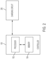
- the vehicle 10 may include a controller, such as controller 100, as is generally illustrated in FIG. 2 .
- the controller 100 may include any suitable controller, such as an electronic control unit or other suitable controller.
- the controller 100 may be configured to control, for example, the various functions of the steering system and/or various functions of the vehicle 10.
- the controller 100 may include a processor 102 and a memory 104.
- the processor 102 may include any suitable processor, such as those described herein. Additionally, or alternatively, the controller 100 may include any suitable number of processors, in addition to or other than the processor 102.
- the memory 104 may comprise a single disk or a plurality of disks (e.g., hard drives), and includes a storage management module that manages one or more partitions within the memory 104.
- memory 104 may include flash memory, semiconductor (solid state) memory or the like.
- the memory 104 may include Random Access Memory (RAM), a Read-Only Memory (ROM), or a combination thereof.
- RAM Random Access Memory
- ROM Read-Only Memory
- the memory 104 may include instructions that, when executed by the processor 102, cause the processor 102 to, at least, control various aspects of the vehicle 10 and/or perform various aspects of the systems and methods described herein.
- the controller 100 may be in communication with a charging circuit 200.
- the charging circuit 200 may be configured to charge at least one high voltage (HV) battery of the vehicle 10,
- HV high voltage
- the circuit 200 e.g., which may be referred to as an OBC
- OBC high voltage battery
- the circuit 200 may be configured to transfer energy from an electrical grid to the HV battery (e.g., which may include any suitable capacity such as 400 volts, 900 volts, and/or the like).
- the charging circuit 200 may include a plurality of electrical components, such as inductors, capacitors, resistors, and the like electrically connected using one or more PCBs. With reference to FIGS. 4A-9 , one or more of the electrical components may be connected to a portion of a corresponding PCB, such as the portion 416 of PCB 414, using a terminal 406.
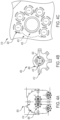
- FIG. 4A generally illustrates a modified choke 404 using a plurality of terminals 406 to comment various electrical components of the choke 404 via the PCB 414.
- the terminal 406 may include a body 408 and a plurality of leads 412 extending from the body at a suitable angle, such as an angle between 180 degrees and 90 degrees relative to a horizontal plane of the body or any other suitable angle.
- the plurality of leads 412 may include any suitable number of leads, such as two, three, four, five, six, or any other suitable number.
- the terminal 406 may include a signal lead 412.
- Each lead of the plurality of leads 412 may be configured to mate with a corresponding mounting locations 420 on the PCB 414. For example, a lead 412 may be inserted in to a hole or opening in the PCB 414 at a corresponding mounting location 420.
- the lead 412 may be coupled, connected, secured, or otherwise attached to the PCB 414 via a connecting material, such as solder or other suitable material, at the corresponding mounting location 420. It should be understood that the leads 412 may be connected to the PCB 414 at the mounting locations 420 using any suitable technique instead of or in addition to those described herein.
- Each lead 412 may be configured to receive current from at least one electrical component associate with the PCB 414.
- a power supply, battery, or other suitable electrical component may provide current to various components of the PCB 414.
- the current may flow through each lead 412 to an electrical component connected to the terminal 406.
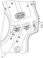
- an electrical component lead 422 may pass through a central bore 424 in body 408 of the terminal 406. This may allow the current to and from the PCB 414 to the component lead 422 such that the current is split among the leads 412.
- the current at each lead 412 is 1/6 th or substantially 1/6 th of the total current flowing to the terminal 406.
- the terminal 406 and/or any terminals described herein may be used with any suitable electrical component, such as inductors, capacitors, resistors, power supplies, and/or the like. Additionally, or alternatively, while the terminal 406 or any terminals described herein may be used in any suitable application, in addition to those described with respect to the vehicle 10 or instead of those described with respect to the vehicle 10.
- the central bore 424 may be defined by an anti-rotation feature 410 the body 408.
- the anti-rotation feature 410 may configured to align the plurality of leads 412 with the mounting locations 420 of by engaging a corresponding portion 418 of the PCB 414.
- the portion 418 of the PCB 414 may include an opening or bore that allows the anti-rotation feature to pass through the PCB 414.
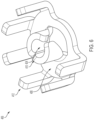
- the terminal 406 as is generally illustrated in FIG. 6 may comprise a unitary component comprising the body 408, the plurality of leads 412, the anti-rotation feature 410, and the central bore 424.
- the terminal 406 may comprise any suitable material include copper, copper alloys, brass, bronze, gold, nickel, tin, and the like.
- the terminal 406 may be shaped from a single piece of material in the manner generally illustrated. The terminal 406 may be bent, punched, extruded, rolled, sanded, heat treated, and the like to form the shape of the terminal 406. It should be understood that the terminal 406 may be manufactured in any suitable manner using any suitable technique.
- an alternative terminal 406' may comprise two or more components.
- the terminal 406' may include a first component comprising a body 408', a plurality of leads 412', and a first central bore 424'.
- the terminal 406' may include a second component comprising an anti-rotation feature 410' and a second central bore 426' defined by the anti-rotation feature 410'.
- Each of the first component and the second component may comprise any suitable material include copper, copper alloys, brass, bronze, gold, nickel, tin, the like, and/or any suitable combination thereof.
- the terminal 406' may be manufactured in any suitable manner using any suitable technique.
- a terminal for a printed circuit board includes a body and a plurality of leads extending from the body at an angle between 180 degrees and 90 degrees relative to a horizontal plane of the body, each lead of the plurality of leads being configured to: mate with a corresponding mounting locations on the printed circuit board; and receive current from at least one electrical component associate with the printed circuit board, wherein the current flows from the at least one electrical component via the plurality of leads to at least one other electrical component.
- the at least one electrical component includes a power supply. In some embodiments, the at least one other electrical component includes a choke inductor. In some embodiments, the at least other electrical component includes a capacitor. In some embodiments, the plurality of leads includes six leads. In some embodiments, the printed circuit board is associated with an on board charger associated with a vehicle battery. In some embodiments, the printed circuit board is associated with a direct current to direct current converter. In some embodiments, the printed circuit board is associated with an inverter. In some embodiments, the body includes an anti-rotation feature of the body, and wherein the anti-rotation feature is configured to align the plurality of leads with the mounting locations of the printed circuit board by engaging a corresponding portion of the printed circuit board. In some embodiments, the body, the plurality of leads, and the anti-rotation feature comprise a unitary component.
- a system in some embodiments, includes a printed circuit board that includes a plurality of mounting locations, a body and a plurality of leads extending from the body at an angle between 180 degrees and 90 degrees relative to a horizontal plane of the body.
- Each lead of the plurality of leads is configured to: mate with respective mounting locations of the plurality of mounting locations on the printed circuit board; and receive current from at least one electrical component associate with the printed circuit board, wherein the current flows from the at least one electrical component via the plurality of leads to at least one other electrical component.
- the at least one electrical component includes a power supply. In some embodiments, the at least one other electrical component includes a choke inductor. In some embodiments, the at least other electrical component includes a capacitor. In some embodiments, the plurality of leads includes six leads. In some embodiments, the printed circuit board is associated with an on board charger associated with a vehicle battery. In some embodiments, the printed circuit board is associated with a direct current to direct current converter. In some embodiments, the printed circuit board is associated with an inverter. In some embodiments, the body includes an anti-rotation feature of the body, and wherein the anti-rotation feature is configured to align the plurality of leads with the mounting locations of the printed circuit board. In some embodiments, the body, the plurality of leads, and the anti-rotation feature comprise a unitary component.
- an apparatus in some embodiments, includes a body that includes at least one anti-rotation feature configured to engage a corresponding portion of a printed circuit board.
- the apparatus also includes a plurality of leads extending from the body and configured to: mate with corresponding mounting locations on the printed circuit board; and receive current from at least one electrical component associate with the printed circuit board, wherein the current flows from the at least one electrical component via the plurality of leads to at least one other electrical component.
- example is used herein to mean serving as an example, instance, or illustration. Any aspect or design described herein as “example” is not necessarily to be construed as preferred or advantageous over other aspects or designs. Rather, use of the word “example” is intended to present concepts in a concrete fashion.
- the term “or” is intended to mean an inclusive “or” rather than an exclusive “or.” That is, unless specified otherwise, or clear from context, "X includes A or B” is intended to mean any of the natural inclusive permutations. That is, if X includes A; X includes B; or X includes both A and B, then "X includes A or B" is satisfied under any of the foregoing instances.
- module can include a packaged functional hardware unit designed for use with other components, a set of instructions executable by a controller (e.g., a processor executing software or firmware), processing circuitry configured to perform a particular function, and a self-contained hardware or software component that interfaces with a larger system.
- a module can include an application specific integrated circuit (ASIC), a Field Programmable Gate Array (FPGA), a circuit, digital logic circuit, an analog circuit, a combination of discrete circuits, gates, and other types of hardware or combination thereof.
- a module can include memory that stores instructions executable by a controller to implement a feature of the module.
- systems described herein can be implemented using a general-purpose computer or general-purpose processor with a computer program that, when executed, carries out any of the respective methods, algorithms, and/or instructions described herein.
- a special purpose computer/processor can be utilized which can contain other hardware for carrying out any of the methods, algorithms, or instructions described herein.
- implementations of the present disclosure can take the form of a computer program product accessible from, for example, a computer-usable or computer-readable medium.
- a computer-usable or computer-readable medium can be any device that can, for example, tangibly contain, store, communicate, or transport the program for use by or in connection with any processor.
- the medium can be, for example, an electronic, magnetic, optical, electromagnetic, or a semiconductor device. Other suitable mediums are also available.
Landscapes
- Engineering & Computer Science (AREA)
- Physics & Mathematics (AREA)
- Electromagnetism (AREA)
- Microelectronics & Electronic Packaging (AREA)
- Power Engineering (AREA)
- Transportation (AREA)
- Mechanical Engineering (AREA)
- Charge And Discharge Circuits For Batteries Or The Like (AREA)
Abstract
Description
- This disclosure relates to electrical terminals, and in particular, systems and methods for providing a magnetic high current printed circuit board mount terminal.
- Vehicles, such as cars, trucks, sport utility vehicles, cross-overs, mini-vans, or other suitable vehicles, typically include various electric components, such as motors (e.g., permanent magnet motors or other suitable electric motors), batteries, battery chargers, and the like. Such electric components may be used for various aspects of vehicle control or operation, such as vehicle prolusion or other suitable aspects of vehicle control or operation.
- Typically, such electrical components may be mounted on and/or connected via a printed circuit board (PCB). The printed circuit board may include a plurality of mounting locations, vias, and the like. The printed circuit board may be configured to electrically connect, using various terminals, connectors, connecting material, and the like, the electrical components.
- This disclosure relates generally to electrical component terminals for printed circuit boards.
- An aspect of the disclosed embodiments includes a terminal for a printed circuit board. The terminal includes a body and a plurality of leads extending from the body at an angle between 180 degrees and 90 degrees relative to a horizontal plane of the body, each lead of the plurality of leads being configured to: mate with a corresponding mounting locations on the printed circuit board; and receive current from at least one electrical component associate with the printed circuit board, wherein the current flows from the at least one electrical component via the plurality of leads to at least one other electrical component.
- Another aspect of the disclosed embodiments includes a system. The system includes a printed circuit board that includes a plurality of mounting locations, a body and a plurality of leads extending from the body at an angle between 180 degrees and 90 degrees relative to a horizontal plane of the body. Each lead of the plurality of leads is configured to: mate with respective mounting locations of the plurality of mounting locations on the printed circuit board; and receive current from at least one electrical component associate with the printed circuit board, wherein the current flows from the at least one electrical component via the plurality of leads to at least one other electrical component.
- Another aspect of the disclosed embodiments includes an apparatus. The apparatus includes a body that includes at least one anti-rotation feature configured to engage a corresponding portion of a printed circuit board. The apparatus also includes a plurality of leads extending from the body and configured to: mate with corresponding mounting locations on the printed circuit board; and receive current from at least one electrical component associate with the printed circuit board, wherein the current flows from the at least one electrical component via the plurality of leads to at least one other electrical component.
- These and other aspects of the present disclosure are provided in the following detailed description of the embodiments, the appended claims, and the accompanying figures.
- The disclosure is best understood from the following detailed description when read in conjunction with the accompanying drawings. It is emphasized that, according to common practice, the various features of the drawings are not to-scale. On the contrary, the dimensions of the various features are arbitrarily expanded or reduced for clarity.
-
FIG. 1 generally illustrates a vehicle according to the principles of the present disclosure. -
FIG. 2 generally illustrates a controller according to the principles of the present disclosure. -
FIG. 3 generally illustrates an electrical connection according to the principles of the present disclosure. -
FIGS. 4A-4C generally illustrate a terminal according to the principles of the present disclosure. -
FIG. 5 generally illustrates an alternative view of the terminal ofFIGS. 4A-4C . -
FIG. 6 generally illustrates another alternative view of the terminal ofFIGS. 4A-4C . -
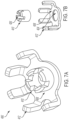
FIGS. 7A and 7B generally illustrate an alternative terminal according to the principles of the present disclosure. -
FIG. 8 generally illustrates shaping or forming steps of a terminal according to the principles of the present disclosure. -
FIG. 9 generally illustrates alternative shaping or forming steps of a terminal according to the principles of the present disclosure. - The following discussion is directed to various embodiments of the invention. Although one or more of these embodiments may be preferred, the embodiments disclosed should not be interpreted, or otherwise used, as limiting the scope of the disclosure, including the claims. In addition, one skilled in the art will understand that the following description has broad application, and the discussion of any embodiment is meant only to be exemplary of that embodiment, and not intended to intimate that the scope of the disclosure, including the claims, is limited to that embodiment.
- As described, vehicles, such as cars, trucks, sport utility vehicles, cross-overs, mini-vans, or other suitable vehicles, typically include various electric components, such as motors (e.g., permanent magnet motors or other suitable electric motors), batteries, battery chargers, and the like. Such electric components may be used for various aspects of vehicle control or operation, such as vehicle prolusion or other suitable aspects of vehicle control or operation.
- Such electrical components may be mounted on and/or connected via a PCB. The printed circuit board may include a plurality of mounting locations, vias, and the like. The printed circuit board may be configured to electrically connect, using various terminals, connectors, connecting material, and the like, the electrical components.
- Increasingly, relatively high current, relatively high power density, and elevated heatsink or ambient temperatures operation of power electronic products, such as on board chargers for vehicle batteries, direct current to direct current (DCDC) converters, inverters and the like are becoming more common in vehicle electronic systems and other suitable electrical applications. Typically, a PCB is used to connect active and/or passive components to various electrical circuits. High current generation may create potential component connection issues to PCBs due to manufacturing constrains on soldering processes and/or materials. The lack or minimized component connections to the PCB creates hotspots, yielding elevated localized temperatures that may increase both the PCB and component operating temperatures, thereby decreasing system efficiency due to higher loss and/or potential failure over time.
-
FIGS. 3A and 3B , generally illustrate an example common mode/differential mode choke. Wire is terminated into a plastic type material base plate that holds it to a specific location.FIG. 3B shows an example of the choke terminal connection to the PCB. Due to solderability constrains of manufacturing, thermal ties are used in place of buried connections to facilitate soldering. From an electrical perspective, the connection is downgraded due to loss of copper that caries the current to or from the PCB to the choke, which may create hotspots. - Accordingly, systems and methods, such as those described herein, configured to provide a terminal that reduces or controls electrical component (e.g., including, but not limited to, magnetic or leaded components) connection temperatures (e.g., and reduces or eliminates hotspots), may be desirable. In some embodiments, the systems and methods described herein may be configured to provide a terminal that splits a single connection to multiple connections between an electrical component and the PCB.
- In some embodiments, a terminal for a printed circuit board includes a body and a plurality of leads extending from the body at an angle between 180 degrees and 90 degrees relative to a horizontal plane of the body. Each lead of the plurality of leads may be configured to mate with a corresponding mounting locations on the printed circuit board, and receive current from at least one electrical component (e.g., which may include a magnetic component, a leaded component, and/or the like) associate with the printed circuit board. The current may flow from the at least one electrical component via the plurality of leads to at least one other electrical component.
- In some embodiments, the at least one electrical component includes a power supply and/or other suitable electrical component. In some embodiments, the at least one other electrical component includes a choke inductor, a capacitor, a resistor, any other suitable electrical component, or a combination thereof. In some embodiments, the plurality of leads includes two leads, three leads, four leads, five leads, six leads, or any suitable number of leads In some embodiments, the printed circuit board is associated with an on board charger associated with a vehicle battery. In some embodiments, the printed circuit board is associated with a direct current to direct current converter. In some embodiments, the printed circuit board is associated with an inverter. In some embodiments, the body includes an anti-rotation feature of the body, and wherein the anti-rotation feature is configured to align the plurality of leads with the mounting locations of the printed circuit board by engaging a corresponding portion of the printed circuit board. In some embodiments, the body, the plurality of leads, and the anti-rotation feature comprise a unitary component.
-
FIG. 1 generally illustrates avehicle 10 according to the principles of the present disclosure. Thevehicle 10 may include any suitable vehicle, such as a car, a truck, a sport utility vehicle, a mini-van, a cross-over, any other passenger vehicle, any suitable commercial vehicle, or any other suitable vehicle. While thevehicle 10 is illustrated as a passenger vehicle having wheels and for use on roads, the principles of the present disclosure may apply to other vehicles, such as planes, boats, trains, drones, or other suitable vehicles. Thevehicle 10 includes avehicle body 12 and ahood 14. A portion of thevehicle body 12 defines apassenger compartment 18. Another portion of thevehicle body 12 defines the engine compartment 20. Thehood 14 may be moveably attached to a portion of thevehicle body 12, such that thehood 14 provides access to the engine compartment 20 when thehood 14 is in a first or open position and thehood 14 covers the engine compartment 20 when thehood 14 is in a second or closed position. - The
passenger compartment 18 is disposed rearward of the engine compartment 20. Thevehicle 10 may include any suitable propulsion system including an internal combustion engine, one or more electric motors (e.g., an electric vehicle), one or more fuel cells, a hybrid (e.g., a hybrid vehicle) propulsion system comprising a combination of an internal combustion engine, one or more electric motors, and/or any other suitable propulsion system. In some embodiments, thevehicle 10 may include a petrol or gasoline fuel engine, such as a spark ignition engine. In some embodiments, thevehicle 10 may include a diesel fuel engine, such as a compression ignition engine. The engine compartment 20 houses and/or encloses at least some components of the propulsion system of thevehicle 10. Additionally, or alternatively, propulsion controls, such as an accelerator actuator (e.g., an accelerator pedal), a brake actuator (e.g., a brake pedal), a steering wheel, and other such components are disposed in thepassenger compartment 18 of thevehicle 10. The propulsion controls may be actuated or controlled by a driver of thevehicle 10 and may be directly connected to corresponding components of the propulsion system, such as a throttle, a brake, a vehicle axle, a vehicle transmission, and the like, respectively. In some embodiments, the propulsion controls may communicate signals to a vehicle computer (e.g., drive by wire) which in turn may control the corresponding propulsion component of the propulsion system. - In some embodiments, the
vehicle 10 includes a transmission in communication with a crankshaft via a flywheel or clutch or fluid coupling. In some embodiments, the transmission includes a manual transmission. In some embodiments, the transmission includes an automatic transmission. Thevehicle 10 may include one or more pistons, in the case of an internal combustion engine or a hybrid vehicle, which cooperatively operate with the crankshaft to generate force, which is translated through the transmission to one or more axles which turnswheels 22. When thevehicle 10 includes one or more electric motors, a vehicle battery and/or fuel cell provides energy to the electric motors to turn thewheels 22. In cases where thevehicle 10 includes a vehicle battery to provide energy to the one or more electric motors, when the battery is depleted, it may be connected to an electric grid (e.g., using a wall socket) to recharge the battery cells. Additionally, or alternatively, thevehicle 10 may employ regenerative braking which uses the one or more electric motors of thevehicle 10 as a generator to convert kinetic energy lost due to decelerating back into stored energy in the battery. - The
vehicle 10 may include automatic vehicle propulsion systems, such as a cruise control, an adaptive cruise control, automatic braking control, other automatic vehicle propulsion systems, or a combination thereof. Thevehicle 10 may be an autonomous or semi-autonomous vehicle, or other suitable type of vehicle. Thevehicle 10 may include additional or fewer features than those generally illustrated and/or disclosed herein. - In some embodiments, the
vehicle 10 may include a controller, such ascontroller 100, as is generally illustrated inFIG. 2 . Thecontroller 100 may include any suitable controller, such as an electronic control unit or other suitable controller. Thecontroller 100 may be configured to control, for example, the various functions of the steering system and/or various functions of thevehicle 10. Thecontroller 100 may include aprocessor 102 and amemory 104. Theprocessor 102 may include any suitable processor, such as those described herein. Additionally, or alternatively, thecontroller 100 may include any suitable number of processors, in addition to or other than theprocessor 102. Thememory 104 may comprise a single disk or a plurality of disks (e.g., hard drives), and includes a storage management module that manages one or more partitions within thememory 104. In some embodiments,memory 104 may include flash memory, semiconductor (solid state) memory or the like. Thememory 104 may include Random Access Memory (RAM), a Read-Only Memory (ROM), or a combination thereof. Thememory 104 may include instructions that, when executed by theprocessor 102, cause theprocessor 102 to, at least, control various aspects of thevehicle 10 and/or perform various aspects of the systems and methods described herein. - The
controller 100 may be in communication with a chargingcircuit 200. The chargingcircuit 200 may be configured to charge at least one high voltage (HV) battery of thevehicle 10, The circuit 200 (e.g., which may be referred to as an OBC) may be configured to transfer energy from an electrical grid to the HV battery (e.g., which may include any suitable capacity such as 400 volts, 900 volts, and/or the like). - The charging
circuit 200 may include a plurality of electrical components, such as inductors, capacitors, resistors, and the like electrically connected using one or more PCBs. With reference toFIGS. 4A-9 , one or more of the electrical components may be connected to a portion of a corresponding PCB, such as theportion 416 ofPCB 414, using aterminal 406.FIG. 4A generally illustrates a modifiedchoke 404 using a plurality ofterminals 406 to comment various electrical components of thechoke 404 via thePCB 414. - The terminal 406 may include a
body 408 and a plurality ofleads 412 extending from the body at a suitable angle, such as an angle between 180 degrees and 90 degrees relative to a horizontal plane of the body or any other suitable angle. The plurality ofleads 412 may include any suitable number of leads, such as two, three, four, five, six, or any other suitable number. In some embodiments, the terminal 406 may include asignal lead 412. Each lead of the plurality ofleads 412 may be configured to mate with a corresponding mountinglocations 420 on thePCB 414. For example, alead 412 may be inserted in to a hole or opening in thePCB 414 at a corresponding mountinglocation 420. Thelead 412 may be coupled, connected, secured, or otherwise attached to thePCB 414 via a connecting material, such as solder or other suitable material, at the corresponding mountinglocation 420. It should be understood that theleads 412 may be connected to thePCB 414 at the mountinglocations 420 using any suitable technique instead of or in addition to those described herein. - Each lead 412 may be configured to receive current from at least one electrical component associate with the
PCB 414. For example, a power supply, battery, or other suitable electrical component may provide current to various components of thePCB 414. The current may flow through each lead 412 to an electrical component connected to the terminal 406. For example, as is generally illustrated inFIG. 5 , anelectrical component lead 422 may pass through acentral bore 424 inbody 408 of the terminal 406. This may allow the current to and from thePCB 414 to thecomponent lead 422 such that the current is split among the leads 412. For example, for a terminal 406 having sixleads 412, the current at each lead 412 is 1/6th or substantially 1/6th of the total current flowing to the terminal 406. This may create a relatively larger connection (e.g., or may reduce connection resistance) from thePCB 414 to thecomponent lead 422, thereby yielding a reduction or elimination of thePCB 414 hotspots. It should be understood that, while a choke 402 is generally described and illustrated, the terminal 406 and/or any terminals described herein may be used with any suitable electrical component, such as inductors, capacitors, resistors, power supplies, and/or the like. Additionally, or alternatively, while the terminal 406 or any terminals described herein may be used in any suitable application, in addition to those described with respect to thevehicle 10 or instead of those described with respect to thevehicle 10. - In some embodiments, as is generally illustrated in
FIGS. 4A, 4B, 4C ,5 , and6 , thecentral bore 424 may be defined by ananti-rotation feature 410 thebody 408. Theanti-rotation feature 410 may configured to align the plurality ofleads 412 with the mountinglocations 420 of by engaging acorresponding portion 418 of thePCB 414. Theportion 418 of thePCB 414 may include an opening or bore that allows the anti-rotation feature to pass through thePCB 414. - In some embodiments, the terminal 406, as is generally illustrated in
FIG. 6 may comprise a unitary component comprising thebody 408, the plurality ofleads 412, theanti-rotation feature 410, and thecentral bore 424. The terminal 406 may comprise any suitable material include copper, copper alloys, brass, bronze, gold, nickel, tin, and the like. With reference toFIGS. 8 and9 , the terminal 406 may be shaped from a single piece of material in the manner generally illustrated. The terminal 406 may be bent, punched, extruded, rolled, sanded, heat treated, and the like to form the shape of the terminal 406. It should be understood that the terminal 406 may be manufactured in any suitable manner using any suitable technique. - In some embodiments, as is generally illustrated in
FIGS. 7A and 7B , an alternative terminal 406' may comprise two or more components. For example, the terminal 406' may include a first component comprising a body 408', a plurality of leads 412', and a first central bore 424'. The terminal 406' may include a second component comprising an anti-rotation feature 410' and a second central bore 426' defined by the anti-rotation feature 410'. Each of the first component and the second component may comprise any suitable material include copper, copper alloys, brass, bronze, gold, nickel, tin, the like, and/or any suitable combination thereof.. It should be understood that the terminal 406' may be manufactured in any suitable manner using any suitable technique. - In some embodiments, a terminal for a printed circuit board includes a body and a plurality of leads extending from the body at an angle between 180 degrees and 90 degrees relative to a horizontal plane of the body, each lead of the plurality of leads being configured to: mate with a corresponding mounting locations on the printed circuit board; and receive current from at least one electrical component associate with the printed circuit board, wherein the current flows from the at least one electrical component via the plurality of leads to at least one other electrical component.
- In some embodiments, the at least one electrical component includes a power supply. In some embodiments, the at least one other electrical component includes a choke inductor. In some embodiments, the at least other electrical component includes a capacitor. In some embodiments, the plurality of leads includes six leads. In some embodiments, the printed circuit board is associated with an on board charger associated with a vehicle battery. In some embodiments, the printed circuit board is associated with a direct current to direct current converter. In some embodiments, the printed circuit board is associated with an inverter. In some embodiments, the body includes an anti-rotation feature of the body, and wherein the anti-rotation feature is configured to align the plurality of leads with the mounting locations of the printed circuit board by engaging a corresponding portion of the printed circuit board. In some embodiments, the body, the plurality of leads, and the anti-rotation feature comprise a unitary component.
- In some embodiments, a system includes a printed circuit board that includes a plurality of mounting locations, a body and a plurality of leads extending from the body at an angle between 180 degrees and 90 degrees relative to a horizontal plane of the body. Each lead of the plurality of leads is configured to: mate with respective mounting locations of the plurality of mounting locations on the printed circuit board; and receive current from at least one electrical component associate with the printed circuit board, wherein the current flows from the at least one electrical component via the plurality of leads to at least one other electrical component.
- In some embodiments, the at least one electrical component includes a power supply. In some embodiments, the at least one other electrical component includes a choke inductor. In some embodiments, the at least other electrical component includes a capacitor. In some embodiments, the plurality of leads includes six leads. In some embodiments, the printed circuit board is associated with an on board charger associated with a vehicle battery. In some embodiments, the printed circuit board is associated with a direct current to direct current converter. In some embodiments, the printed circuit board is associated with an inverter. In some embodiments, the body includes an anti-rotation feature of the body, and wherein the anti-rotation feature is configured to align the plurality of leads with the mounting locations of the printed circuit board. In some embodiments, the body, the plurality of leads, and the anti-rotation feature comprise a unitary component.
- In some embodiments, an apparatus includes a body that includes at least one anti-rotation feature configured to engage a corresponding portion of a printed circuit board. The apparatus also includes a plurality of leads extending from the body and configured to: mate with corresponding mounting locations on the printed circuit board; and receive current from at least one electrical component associate with the printed circuit board, wherein the current flows from the at least one electrical component via the plurality of leads to at least one other electrical component.
- The above discussion is meant to be illustrative of the principles and various embodiments of the present disclosure. Numerous variations and modifications will become apparent to those skilled in the art once the above disclosure is fully appreciated. It is intended that the following claims be interpreted to embrace all such variations and modifications.
- The word "example" is used herein to mean serving as an example, instance, or illustration. Any aspect or design described herein as "example" is not necessarily to be construed as preferred or advantageous over other aspects or designs. Rather, use of the word "example" is intended to present concepts in a concrete fashion. As used in this application, the term "or" is intended to mean an inclusive "or" rather than an exclusive "or." That is, unless specified otherwise, or clear from context, "X includes A or B" is intended to mean any of the natural inclusive permutations. That is, if X includes A; X includes B; or X includes both A and B, then "X includes A or B" is satisfied under any of the foregoing instances. In addition, the articles "a" and "an" as used in this application and the appended claims should generally be construed to mean "one or more" unless specified otherwise or clear from context to be directed to a singular form. Moreover, use of the term "an implementation" or "one implementation" throughout is not intended to mean the same embodiment or implementation unless described as such.
- Implementations of the systems, algorithms, methods, instructions, etc., described herein can be realized in hardware, software, or any combination thereof. The hardware can include, for example, computers, intellectual property (IP) cores, application-specific integrated circuits (ASICs), programmable logic arrays, optical processors, programmable logic controllers, microcode, microcontrollers, servers, microprocessors, digital signal processors, or any other suitable circuit. In the claims, the term "processor" should be understood as encompassing any of the foregoing hardware, either singly or in combination. The terms "signal" and "data" are used interchangeably.
- As used herein, the term module can include a packaged functional hardware unit designed for use with other components, a set of instructions executable by a controller (e.g., a processor executing software or firmware), processing circuitry configured to perform a particular function, and a self-contained hardware or software component that interfaces with a larger system. For example, a module can include an application specific integrated circuit (ASIC), a Field Programmable Gate Array (FPGA), a circuit, digital logic circuit, an analog circuit, a combination of discrete circuits, gates, and other types of hardware or combination thereof. In other embodiments, a module can include memory that stores instructions executable by a controller to implement a feature of the module.
- Further, in one aspect, for example, systems described herein can be implemented using a general-purpose computer or general-purpose processor with a computer program that, when executed, carries out any of the respective methods, algorithms, and/or instructions described herein. In addition, or alternatively, for example, a special purpose computer/processor can be utilized which can contain other hardware for carrying out any of the methods, algorithms, or instructions described herein.
- Further, all or a portion of implementations of the present disclosure can take the form of a computer program product accessible from, for example, a computer-usable or computer-readable medium. A computer-usable or computer-readable medium can be any device that can, for example, tangibly contain, store, communicate, or transport the program for use by or in connection with any processor. The medium can be, for example, an electronic, magnetic, optical, electromagnetic, or a semiconductor device. Other suitable mediums are also available.
- The above-described embodiments, implementations, and aspects have been described to allow easy understanding of the present disclosure and do not limit the present disclosure. On the contrary, the disclosure is intended to cover various modifications and equivalent arrangements included within the scope of the appended claims, which scope is to be accorded the broadest interpretation to encompass all such modifications and equivalent structure as is permitted under the law.
Claims (14)
- A terminal for a printed circuit board, the terminal comprising:a body; anda plurality of leads extending from the body at an angle between 180 degrees and 90 degrees relative to a horizontal plane of the body, each lead of the plurality of leads being configured to:mate with a corresponding mounting location on the printed circuit board; andreceive current from at least one electrical component associate with the printed circuit board, wherein the current flows from the at least one electrical component via the plurality of leads to at least one other electrical component.
- The terminal of claim 1, wherein the at least one electrical component includes a power supply.
- The terminal of any one of claims 1 or 2, wherein the at least one other electrical component includes a choke inductor and/or wherein the at least one other electrical component includes a capacitor.
- The terminal of any one of claims 1 to 3, wherein the plurality of leads includes six leads.
- The terminal of any one of claims 1 to 4, wherein the printed circuit board is associated with an on board charger associated with a vehicle battery, and/or wherein the printed circuit board is associated with a direct current to direct current converter and/or wherein the printed circuit board is associated with an inverter.
- The terminal of any one of claims 1 to 5, wherein the body includes an anti-rotation feature, and wherein the anti-rotation feature is configured to align the plurality of leads with the mounting locations of the printed circuit board by engaging a corresponding portion of the printed circuit board.
- The terminal of claim 6, wherein the body, the plurality of leads, and the anti-rotation feature comprise a unitary component.
- A system comprising:a printed circuit board that includes a plurality of mounting locations;a body; anda plurality of leads extending from the body at an angle between 180 degrees and 90 degrees relative to a horizontal plane of the body, each lead of the plurality of leads being configured to:mate with respective mounting locations of the plurality of mounting locations on the printed circuit board; andreceive current from at least one electrical component associate with the printed circuit board, wherein the current flows from the at least one electrical component via the plurality of leads to at least one other electrical component.
- The system of claim 8, wherein the at least one electrical component includes a power supply.
- The system of any one of claims 8 to 9, wherein the at least one other electrical component includes a choke inductor and/or wherein the at least one other electrical component includes a capacitor.
- The system of any one of claims 8 to 10, wherein the plurality of leads includes six leads.
- The system of any one of claims 8 to 11, wherein the printed circuit board is associated with an on board charger associated with a vehicle battery, and/or wherein the printed circuit board is associated with a direct current to direct current converter and/or wherein the printed circuit board is associated with an inverter.
- The system of any one of claims 8 to 12, wherein the body includes an anti-rotation feature, and wherein the anti-rotation feature is configured to align the plurality of leads with the mounting locations of the printed circuit board.
- An apparatus comprising:a body that includes at least one anti-rotation feature configured to engage a corresponding portion of a printed circuit board; anda plurality of leads extending from the body and configured to:mate with corresponding mounting locations on the printed circuit board; andreceive current from at least one electrical component associate with the printed circuit board, wherein the current flows from the at least one electrical component via the plurality of leads to at least one other electrical component.
Applications Claiming Priority (1)
| Application Number | Priority Date | Filing Date | Title |
|---|---|---|---|
| US18/318,503 US12620735B2 (en) | 2023-06-06 | 2023-06-06 | High current printed circuit board mount terminal for magnetic or leaded components |
Publications (1)
| Publication Number | Publication Date |
|---|---|
| EP4518036A1 true EP4518036A1 (en) | 2025-03-05 |
Family
ID=91129036
Family Applications (1)
| Application Number | Title | Priority Date | Filing Date |
|---|---|---|---|
| EP24176219.4A Pending EP4518036A1 (en) | 2023-06-06 | 2024-05-16 | Printed circuit board mount terminal for high-current applications |
Country Status (2)
| Country | Link |
|---|---|
| US (1) | US12620735B2 (en) |
| EP (1) | EP4518036A1 (en) |
Citations (8)
| Publication number | Priority date | Publication date | Assignee | Title |
|---|---|---|---|---|
| EP0527243A1 (en) * | 1991-08-02 | 1993-02-17 | Grote & Hartmann GmbH & Co. KG | Solder terminal with contract pin |
| US20040161975A1 (en) * | 2003-02-07 | 2004-08-19 | Shuhei Sakai | Power supply terminal |
| DE102004022791B4 (en) * | 2004-05-08 | 2007-01-04 | Tyco Electronics Amp Gmbh | Clamping contact for a printed circuit board and / or stamped grid and arrangement of printed circuit boards and / or stamped grid |
| US20120129362A1 (en) * | 2010-11-24 | 2012-05-24 | Lear Corporation | Printed circuit board connection assembly |
| US20190097331A1 (en) * | 2017-09-25 | 2019-03-28 | Ge Aviation Systems Limited | Surface mount connector and method of forming a printed circuit board |
| US20190267731A1 (en) * | 2018-02-23 | 2019-08-29 | Borgwarner Inc. | Contact assembly for high-current applications |
| DE102018005359A1 (en) * | 2018-07-05 | 2020-01-09 | Mtconnectivity Power2Pcb Gmbh | Contact element with a printed circuit board |
| DE102019214012A1 (en) * | 2019-09-13 | 2021-03-18 | E.G.O. Elektro-Gerätebau GmbH | Contact socket, circuit board arrangement and connector system with it |
Family Cites Families (2)
| Publication number | Priority date | Publication date | Assignee | Title |
|---|---|---|---|---|
| FR3084970B1 (en) * | 2018-08-13 | 2021-12-10 | Valeo Siemens Eautomotive France Sas | ELECTRICAL EQUIPMENT |
| US11936128B2 (en) * | 2021-02-09 | 2024-03-19 | Lear Corporation | Electrical unit with offset terminals |
-
2023
- 2023-06-06 US US18/318,503 patent/US12620735B2/en active Active
-
2024
- 2024-05-16 EP EP24176219.4A patent/EP4518036A1/en active Pending
Patent Citations (8)
| Publication number | Priority date | Publication date | Assignee | Title |
|---|---|---|---|---|
| EP0527243A1 (en) * | 1991-08-02 | 1993-02-17 | Grote & Hartmann GmbH & Co. KG | Solder terminal with contract pin |
| US20040161975A1 (en) * | 2003-02-07 | 2004-08-19 | Shuhei Sakai | Power supply terminal |
| DE102004022791B4 (en) * | 2004-05-08 | 2007-01-04 | Tyco Electronics Amp Gmbh | Clamping contact for a printed circuit board and / or stamped grid and arrangement of printed circuit boards and / or stamped grid |
| US20120129362A1 (en) * | 2010-11-24 | 2012-05-24 | Lear Corporation | Printed circuit board connection assembly |
| US20190097331A1 (en) * | 2017-09-25 | 2019-03-28 | Ge Aviation Systems Limited | Surface mount connector and method of forming a printed circuit board |
| US20190267731A1 (en) * | 2018-02-23 | 2019-08-29 | Borgwarner Inc. | Contact assembly for high-current applications |
| DE102018005359A1 (en) * | 2018-07-05 | 2020-01-09 | Mtconnectivity Power2Pcb Gmbh | Contact element with a printed circuit board |
| DE102019214012A1 (en) * | 2019-09-13 | 2021-03-18 | E.G.O. Elektro-Gerätebau GmbH | Contact socket, circuit board arrangement and connector system with it |
Also Published As
| Publication number | Publication date |
|---|---|
| US20240413551A1 (en) | 2024-12-12 |
| US12620735B2 (en) | 2026-05-05 |
Similar Documents
| Publication | Publication Date | Title |
|---|---|---|
| CN106183767B (en) | Electric Vehicles and Battery Packs | |
| CN104002744B (en) | The integrated type electrical power control unit of vehicle | |
| CN104602946B (en) | Battery system, maintenance switching units and the method for manufacturing battery system | |
| EP1788596A1 (en) | Capacitor module, power converter and vehicle-mounted electrical-mechanical system | |
| CN107107771B (en) | Integrated connectors with sensing and switching conductors for relays used in battery modules | |
| CN113097172B (en) | Electronic power module assembly and control logic with direct cooling vapor chamber system | |
| US20130252052A1 (en) | Integrated Busbar, Terminal Pin And Circuit Protection For Sensing Individual Battery Cell Voltage | |
| US9692031B2 (en) | Bus bar assembly for electrified vehicle batteries | |
| CN101859958A (en) | Be used for electro-motor is connected to the connector assembly of power source | |
| CN113366693B (en) | Mounting clips for printed circuit boards | |
| CN107004791B (en) | Female terminals in the module body | |
| US12620735B2 (en) | High current printed circuit board mount terminal for magnetic or leaded components | |
| US20130260182A1 (en) | PCB with Both High and Low Current Traces for Energy Storage Modules | |
| JP2015053145A (en) | Secondary battery module | |
| CN115694127A (en) | Power converter bus bar | |
| US20240286506A1 (en) | On-board charger with simultaneous charge and discharge capability | |
| US10523109B2 (en) | Vehicle capacitor assembly | |
| US12088284B2 (en) | Discrete relay driver circuit for peak and hold operation | |
| US20250350197A1 (en) | Systems and methods for voltage conversion | |
| CN109552220B (en) | Vehicle-mounted power supply | |
| KR20240087372A (en) | Multi power card and power converting module including the same | |
| Hassan et al. | Development and installation of battery-powered electric vehicle wiring system | |
| Wondrak et al. | Modular concept for power electronics in electric cars | |
| CN223686378U (en) | Domain controller and vehicle | |
| JP2021170466A (en) | Power distribution device |
Legal Events
| Date | Code | Title | Description |
|---|---|---|---|
| PUAI | Public reference made under article 153(3) epc to a published international application that has entered the european phase |
Free format text: ORIGINAL CODE: 0009012 |
|
| STAA | Information on the status of an ep patent application or granted ep patent |
Free format text: STATUS: THE APPLICATION HAS BEEN PUBLISHED |
|
| AK | Designated contracting states |
Kind code of ref document: A1 Designated state(s): AL AT BE BG CH CY CZ DE DK EE ES FI FR GB GR HR HU IE IS IT LI LT LU LV MC ME MK MT NL NO PL PT RO RS SE SI SK SM TR |
|
| RAP1 | Party data changed (applicant data changed or rights of an application transferred) |
Owner name: BORGWARNER US TECHNOLOGIES LLC |
|
| STAA | Information on the status of an ep patent application or granted ep patent |
Free format text: STATUS: REQUEST FOR EXAMINATION WAS MADE |
|
| 17P | Request for examination filed |
Effective date: 20250904 |
|
| P01 | Opt-out of the competence of the unified patent court (upc) registered |
Free format text: CASE NUMBER: UPC_APP_0002921_4518036/2026 Effective date: 20260128 |