EP4518032A1 - Communication system, radio wave refraction plate, and method for calculating placement position of radio wave refraction plate - Google Patents
Communication system, radio wave refraction plate, and method for calculating placement position of radio wave refraction plate Download PDFInfo
- Publication number
- EP4518032A1 EP4518032A1 EP23796157.8A EP23796157A EP4518032A1 EP 4518032 A1 EP4518032 A1 EP 4518032A1 EP 23796157 A EP23796157 A EP 23796157A EP 4518032 A1 EP4518032 A1 EP 4518032A1
- Authority
- EP
- European Patent Office
- Prior art keywords
- radio wave
- wave refraction
- plates
- fresnel zone
- refraction plates
- Prior art date
- Legal status (The legal status is an assumption and is not a legal conclusion. Google has not performed a legal analysis and makes no representation as to the accuracy of the status listed.)
- Withdrawn
Links
Images




Classifications
-
- H—ELECTRICITY
- H01—ELECTRIC ELEMENTS
- H01Q—ANTENNAS, i.e. RADIO AERIALS
- H01Q15/00—Devices for reflection, refraction, diffraction or polarisation of waves radiated from an antenna, e.g. quasi-optical devices
- H01Q15/02—Refracting or diffracting devices, e.g. lens, prism
-
- H—ELECTRICITY
- H01—ELECTRIC ELEMENTS
- H01Q—ANTENNAS, i.e. RADIO AERIALS
- H01Q1/00—Details of, or arrangements associated with, antennas
- H01Q1/12—Supports; Mounting means
- H01Q1/22—Supports; Mounting means by structural association with other equipment or articles
- H01Q1/24—Supports; Mounting means by structural association with other equipment or articles with receiving set
- H01Q1/241—Supports; Mounting means by structural association with other equipment or articles with receiving set used in mobile communications, e.g. GSM
- H01Q1/246—Supports; Mounting means by structural association with other equipment or articles with receiving set used in mobile communications, e.g. GSM specially adapted for base stations
-
- H—ELECTRICITY
- H01—ELECTRIC ELEMENTS
- H01Q—ANTENNAS, i.e. RADIO AERIALS
- H01Q15/00—Devices for reflection, refraction, diffraction or polarisation of waves radiated from an antenna, e.g. quasi-optical devices
- H01Q15/02—Refracting or diffracting devices, e.g. lens, prism
- H01Q15/08—Refracting or diffracting devices, e.g. lens, prism formed of solid dielectric material
-
- H—ELECTRICITY
- H01—ELECTRIC ELEMENTS
- H01Q—ANTENNAS, i.e. RADIO AERIALS
- H01Q19/00—Combinations of primary active antenna elements and units with secondary devices, e.g. with quasi-optical devices, for giving the antenna a desired directional characteristic
- H01Q19/06—Combinations of primary active antenna elements and units with secondary devices, e.g. with quasi-optical devices, for giving the antenna a desired directional characteristic using refracting or diffracting devices, e.g. lens
- H01Q19/062—Combinations of primary active antenna elements and units with secondary devices, e.g. with quasi-optical devices, for giving the antenna a desired directional characteristic using refracting or diffracting devices, e.g. lens for focusing
Definitions
- the present disclosure relates to a communication system, a radio wave refraction plate, and a method for calculating an installation position of a radio wave refraction plate.
- Patent Document 1 describes a technique of refracting radio waves by changing parameters of respective elements in a structure including an array of resonator elements.
- Patent Document 1 JP 2015-231182 A
- a communication system of the present disclosure includes: a base station configured to transmit and receive a radio wave; a terminal configured to transmit and receive the radio wave to and from the base station; and a plurality of radio wave refraction plates installed on the same plane between the base station and the terminal and configured to refract the radio wave and emit a refracted radio wave in a direction of the terminal when the radio wave transmitted from the base station passes through each of the plurality of radio wave refraction plates.
- a plurality of radio wave refraction plates of the present disclosure is installed on the same plane between a base station configured to transmit and receive a radio wave and a terminal configured to transmit and receive the radio wave to and from the base station and configured to refract the radio wave and emit a refracted radio wave in a direction of the terminal when the radio wave transmitted from the base station passes through each of the plurality of radio wave refraction plates.
- a method for calculating an installation position of a radio wave refraction plate includes: calculating a geometric center of center points of a plurality of radio wave refraction plates installed; setting a plane that passes through the geometric center and is orthogonal to a straight line connecting a transmission point at which a radio wave is transmitted to the plurality of radio wave refraction plates and a reception point at which the radio wave refracted by the radio wave refraction plates is received; projecting the plurality of radio wave refraction plates on the plane; and calculating installation positions of the plurality of radio wave refraction plates with an area of each of the plurality of radio wave refraction plates on the plane included in an odd-order Fresnel zone being larger than an area of each of the plurality of radio wave refraction plates on the plane included in an even-order Fresnel zone.
- an XYZ orthogonal coordinate system is set, and the positional relationship between respective portions will be described by referring to the XYZ orthogonal coordinate system.
- a direction parallel to an X-axis in a horizontal plane is defined as an X-axis direction
- a direction parallel to a Y-axis orthogonal to the X-axis in the horizontal plane is defined as a Y-axis direction
- a direction parallel to a Z-axis orthogonal to the horizontal plane is defined as a Z-axis direction.
- a plane including the X-axis and the Y-axis is appropriately referred to as an XY plane.
- a plane including the X-axis and the Z-axis is appropriately referred to as an XZ plane.
- a plane including the Y-axis and the Z-axis is appropriately referred to as a YZ plane.
- the XY plane is parallel to the horizontal plane.
- the XY plane, the XZ plane, and the YZ plane are orthogonal to each other.
- FIG. 1 illustrates a configuration example of a communication system according to the embodiment.
- a communication system 1 includes a base station 10, a terminal 12, and a plurality of radio wave refraction plates 14.
- the communication system 1 may be, for example, a communication system supporting a millimeter wave communication capable of performing large-capacity data communication in high speed, such as the fifth generation mobile communication system (hereinafter, also referred to as the "5G”) or the sixth generation mobile communication system (hereinafter, also referred to as the "6G").
- 5G fifth generation mobile communication system
- 6G sixth generation mobile communication system
- the terminal 12 is a wireless communication device configured to transmit and receive radio waves to and from various external devices.
- the terminal 12 is configured to wirelessly communicate with the base station 10 by transmitting and receiving radio waves corresponding to the 5G or 6G to and from the base station 10.
- the terminal 12 is configured to wirelessly communicate with the base station 10 via the plurality of radio wave refraction plates 14 installed on the same plane.
- a smartphone used by a user is exemplified, but the present disclosure is not limited thereto.
- the terminal 12 may be a relay device that relays communication between the base station 10 and a smartphone used by a user.
- the radio wave refraction plates 14 are plate-shaped members configured to be permeable to the radio waves transmitted from the base station 10.
- the radio wave refraction plates 14 are configured to refract the radio wave at a predetermined angle and emit a refracted radio wave upon receipt of the radio wave transmitted from the base station 10.
- the radio wave refraction plates 14 upon receipt of the radio wave transmitted from the base station 10, are configured to refract the radio wave in a direction of the terminal 12 and emit the radio wave toward the terminal 12.
- the radio wave refraction plates 14 may be made of, for example, a metamaterial that changes a phase of the incident light.
- FIG. 2 is a diagram schematically illustrating an example of the radio wave refraction plate 14.
- the radio wave refraction plate 14 may include a substrate 20 and elements 22, 24, 26, and 28, for example.
- the elements 22, the elements 24, the elements 26, and the elements 28 may be formed on the substrate 20.
- the substrate 20 may have a rectangular shape, for example, but is not limited thereto.
- the elements 22, 24, 26, and 28 may be two-dimensionally arranged on the substrate 20. Specifically, in FIG. 2 , a plurality of elements 22 may be arranged in a line in the bottom row of the substrate 20. On the substrate 20, a plurality of elements 24 may be arranged in a line in a row above the row where the elements 22 are arranged. On the substrate 20, a plurality of elements 26 may be arranged in a line in a row above the row where the elements 24 are arranged.
- a plurality of elements 28 may be arranged in a line in a row above the row where the elements 26 are arranged. That is, the radio wave refraction plate 14 may have a structure in which a plurality of elements having different sizes is periodically arranged.
- the elements 22 to 28 may be different in the frequency band of the radio wave to be changed and the amount of change in the phase.
- the elements 22 to 28 have the rectangular shapes, without limitation. A frequency band and a phase change amount of the radio wave to be refracted can be adjusted by changing the sizes and shapes of the elements 22, 24, 26, and 28.
- the communication system 1 includes the plurality of radio wave refraction plates 14 in the present embodiment.
- the plurality of radio wave refraction plates 14 may be installed on the same plane 16.
- the example illustrated in FIG. 1 includes four radio wave refraction plates 14 installed on the plane 16, but this is merely an example and does not limit the present disclosure.
- the plane 16 may be a space, or a surface of a transparent structure such as a window glass.
- the plurality of radio wave refraction plates 14 refracts a radio wave W1 from the base station 10 and emits it as a refracted radio wave W2 to the terminal 12.
- FIGs. 3 and 4 are diagrams for explaining a radio wave reception method according to a comparative example of the present embodiment.
- the comparative example illustrates a method for reflecting a radio wave from the base station 10 and receiving it by the terminal 12.
- the example illustrated in FIG. 3 includes two radio wave reflective plates: a radio wave reflective plate 30-1 and a radio wave reflective plate 30-2.
- the radio wave reflective plate 30-1 and the radio wave reflective plate 30-2 are configured to reflect a radio wave W1 transmitted from the base station 10 at a predetermined angle as a reflected radio wave W3.
- the arrows assigned to the radio wave W1 and the reflected radio wave W3 indicate traveling directions of the radio wave W1 and the reflected radio wave W3, respectively.
- the radio wave reflective plate 30-1 and the radio wave reflective plate 30-2 are installed at an interval from each other from the origin O along the Z-axis direction so as to strengthen the phases of the reflected radio waves W3 reflected by the reflective plates 30-1 and 30-2. For example, in the example illustrated in FIG.
- the reflected radio wave W3 reflected by the radio wave reflective plate 30-1 and the reflected radio wave W3 reflected by the radio wave reflective plate 30-2 are in the same phase at positions on a straight line 41 on the ZX plane. That is, the received power of the reflected radio wave W3 reflected by the radio wave reflective plate 30-1 and the received power of the reflected radio wave W3 reflected by the radio wave reflective plate 30-2 strengthen each other at positions on the straight line 41 on the ZX plane.
- FIG. 4 illustrates an example in which the radio wave reflective plate 30-2 is shifted by ⁇ /4 from the origin O to the positive direction side of the X-axis, where ⁇ is the wavelength of the radio wave W1.
- ⁇ /4 is 2.7 millimeters (mm) when ⁇ is 28 gigahertz (GHz).
- the reflected radio wave W3 reflected by the radio wave reflective plate 30-1 and the reflected radio wave W3 reflected by the radio wave reflective plate 30-2 are in opposite phases at positions on the straight line 41 on the ZX plane.
- the received power of the reflected radio wave W3 reflected by the radio wave reflective plate 30-1 and the received power of the reflected radio wave W3 reflected by the radio wave reflective plate 30-2 weaken each other at positions on the straight line 41 on the ZX plane.
- the reflected radio waves do not necessarily strengthen each other, and the received power may not be enhanced.
- FIGs. 5 and 6 are diagrams for explaining the radio wave reception method according to the present embodiment.
- the example illustrated in FIG. 5 includes two refraction plates: a radio wave refraction plate 14-1 and a radio wave refraction plate 14-2.
- the radio wave refraction plate14-1 and the radio wave refraction plate14-2 are configured to reflect the radio wave W1 transmitted from the base station 10 at a predetermined angle ⁇ as the refracted radio wave W2.
- arrows assigned to the radio wave W1 and the refracted radio wave W2 indicate the traveling directions of the radio wave W1 and the refracted radio wave W2, respectively.
- the radio wave refraction plate 14-1 and the radio wave refraction plate 14-2 are installed at an interval from each other along the Z-axis direction from the origin O so as to strengthen the phases of the radio waves W2 refracted, respectively.
- the refracted radio wave W2 refracted by the radio wave refraction plate 14-1 and the refracted radio wave W2 refracted by the radio wave refraction plate 14-2 are in the same phase. That is, the received power of the refracted radio wave W2 refracted by the radio wave refraction plate 14-1 and the received power of the refracted radio wave W2 refracted by the radio wave refraction plate 14-2 strengthen each other at positions on the straight line 32 on the ZX plane.
- FIG. 6 illustrates an example in which the radio wave refraction plate 14-2 is shifted by ⁇ /4 from the origin O to the positive direction side of the X-axis, where ⁇ is the wavelength of the radio wave W1.
- ⁇ is the wavelength of the radio wave W1.
- the path length does not substantially change.
- the refracted radio wave W2 refracted by the radio wave refraction plate 14-1 and the refracted radio wave W2 refracted by the radio wave refraction plate 14-2 are in the same phase at positions on the straight line 32 on the ZX plane. That is, in the present embodiment, since the received power is not weakened, the received power can be increased by increasing the areas of the reflective plates using the plurality of radio wave reflective plates.
- the interval between the radio wave refraction plates 14-1 and 14-2 is s
- the refraction angle of the refracted radio wave W2 is ⁇
- the deviation between the radio wave refraction plate 14-1 and the radio wave refraction plate 14-2 in the thickness direction is preferably s/tan ⁇ or less. Making the deviation in the thickness direction (the X-axis direction in FIG. 5 ) of the radio wave refraction plate 14-1 and the radio wave refraction plate 14-2 s/tan ⁇ or less can increase the received power.
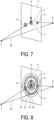
- FIG. 7 is a diagram for explaining the installation method of the radio wave refraction plates according to the present embodiment.
- the path of the radio wave from the transmission point T to the reception point R passing through a point on the radio wave refraction plate 14 is considered, and the radio wave refraction plate 14 is installed with the area installed in an area where the radio waves strengthen each other being larger than the area installed in an area where the radio waves weaken each other.
- the present embodiment can obtain higher received power.
- a region in which radio waves strengthen each other is referred to as an odd-order Fresnel zone
- a region in which radio waves weaken each other is referred to as an even-order Fresnel zone.
- a definition of a Fresnel zone according to the present embodiment is described.
- a situation in which a radio wave from the transmission point T passes through the plurality of radio wave refraction plates 14 and reaches the reception point R is considered.
- the transmission point T indicates the position of an antenna of the base station 10, and the reception point R indicates the position of an antenna of the terminal 12.
- a geometric center (gravity center) of the center points of the plurality of radio wave refraction plates 14 is defined as a geometric center C.
- d 1 be a linear distance between the transmission point T and the geometric center C.
- d 2 be a distance between the reception point R and the geometric center C.
- a plane P that passes through the geometric center C and is orthogonal to a straight line TR connecting the transmission point T and the reception point R is considered.
- a circle centered at the geometric center C and having a radius defined by Equation (1) is considered.
- Equation (1) n is a natural number, and ⁇ is a wavelength of the radio wave.
- FIG. 8 is a diagram for explaining Fresnel zones according to the present embodiment.
- an annular portion in a range from a radius R n-1 to a radius R n is defined as an n-th Fresnel zone.
- the example illustrated in FIG. 8 includes a first Fresnel zone 50, a second Fresnel zone 52, a third Fresnel zone 54, and a fourth Fresnel zone 56.
- FIG. 9 is a flowchart illustrating a process flow for calculating an installation position of the radio wave refraction plate according to the present embodiment.
- the processing illustrated in FIG. 9 is processing executed by an information processing device such as a personal computer (not illustrated).
- the information processing device calculates the geometric center C of the center points of the plurality of installed radio wave refraction plates 14 (step S10). Subsequently, the process proceeds to step S12.
- the information processing device sets the plane P that passes through the geometric center C and is orthogonal to the straight line TR connecting the transmission point T and the reception point R (step S12). Subsequently, the process proceeds to step S14.
- the information processing device projects the plurality of radio wave refraction plates 14 on the plane P (step S14). Subsequently, the process proceeds to step S16.
- the information processing device calculates the installation positions of the plurality of radio wave refraction plates 14 (step S16). Specifically, the information processing device calculates the installation positions of the plurality of radio wave refraction plates 14 such that the areas of the radio wave refraction plates 14 included in the odd-order Fresnel zone are larger than the areas of the radio wave refraction plates 14 included in the even-order Fresnel zone. More specifically, in the example illustrated in FIG.
- the installation positions of the plurality of radio wave refraction plates 14 are calculated such that the areas of the radio wave refraction plates 14 included in the first Fresnel zone 50 and the third Fresnel zone 54 are larger than the areas of the radio wave refraction plates 14 included in the second Fresnel zone 52 and the fourth Fresnel zone 56. Subsequently, the process proceeds to step S18.
- the information processing device outputs installation position information on the installation positions of the plurality of radio wave refraction plates 14 (step S18). Accordingly, the user can adjust the installation positions of the plurality of radio wave refraction plates 14 based on the installation position information.
- a method for setting a distance between the terminal 12 and the plurality of radio wave refraction plates 14 according to the present embodiment is described.
- a linear distance between the reception point R and the geometric center C of the center points of the plurality of radio wave refraction plates 14 is d 2
- the sum of maximum dimensions (e.g., diagonal lines) of the plurality of installed radio wave refraction plates 14 is L sum
- d 2 preferably satisfies the following Expression (2). [Math 2] d 2 > 0.62 L sum 3 ⁇
- FIG. 10 is a graph for explaining the angular dependence of the received power according to the comparative example.
- FIG. 11 is a graph for explaining the angular dependence of the received power according to the embodiment.
- FIG. 10 shows the angular dependence of the received power when the above Expression (2) is not satisfied. Specifically, FIG. 10 shows the angular dependence when the d 2 is 0.75 m, L sum is 0.6 m, and ⁇ is 28 GHz.
- FIG. 10 shows a waveform 101 and a waveform 102.
- the horizontal axis represents the refraction angle [deg (degree)] and the vertical axis represents the gain [dB].
- the waveform 101 indicates the angular dependence of the received power when one radio wave refraction plate 14 is installed.
- the waveform 102 indicates the angular dependence of the received power when two radio wave refraction plates 14 are installed. As indicated by the waveform 101 and the waveform 102, the power distribution of the refracted radio waves is widened by installing two radio wave refraction plates 14.
- FIG. 11 shows the angular dependence of the received power when the above Expression (2) is satisfied. Specifically, FIG. 11 shows the angular dependence of received power when d 2 is 5.0 m, L sum is 0.6 m, and ⁇ is 28 GHz.
- FIG. 11 shows a waveform 103 and a waveform 104.
- the horizontal axis represents the refraction angle [deg] and the vertical axis represents the gain [dB].
- the waveform 103 indicates the angular dependence of the received power when one radio wave refraction plate 14 is installed.
- the waveform 104 indicates the angular dependence of received power when two radio wave refraction plates 14 are installed. As indicated by the waveform 103 and the waveform 104, the gain of the received power increases and the power distribution is narrowed by installing two radio wave refraction plates 14.
- a preferred method for installing the radio wave refraction plates 14 in installing the plurality of radio wave refraction plates 14 adjacent to other radio wave refraction plates 14 is described.
- FIGs. 12 and 13 are graphs for explaining permeability properties of the radio wave refraction plates installed adjacent to each other according to the embodiment.
- the radio wave refraction plate 14-1 and the radio wave refraction plate 14-2 are installed with the area included in the odd-order Fresnel zone being larger than the area included in the even-order Fresnel zone and are installed adjacent to each other.
- the radio wave refraction plate 14-1 and the radio wave refraction plate 14-2 may be installed in the same odd-order Fresnel zone or may be installed in different odd-order Fresnel zones.
- the radio wave refraction plate 14-1 includes elements 22A, 24A, and 26A.
- the radio wave refraction plate 14-2 includes elements 22B and 24B.
- the elements 22A, 24A, 26A, and the like are installed adjacent to the elements 22B, 24B, and the like.
- the horizontal axis represents the installation position of the radio wave refraction plates 14, and the vertical axis represents the phase change amount [degree].
- a point P1 indicates the installation position and the phase change amount of the element 22A.
- a point P2 indicates the installation position and the phase change amount of the element 24A.
- a point P3 indicates the installation position and the phase change amount of the element 26A.
- a point P4 indicates the installation position and the phase change amount of the element 22B.
- a point P5 indicates the installation position and the phase change amount of the element 24B.
- the radio wave refraction plate 14-1 and the radio wave refraction plate 14-2 are installed so that the points P1 to P5 are on a straight line 61 in the present embodiment. Accordingly, the radio wave refraction plate 14-1 and the radio wave refraction plate 14-2 can increase the received power of the refracted radio wave and can further improve the properties.
- the radio wave refraction plate 14-1 is installed so that the area included in the odd-order Fresnel zone is larger than the area included in the even-order Fresnel zone.
- the radio wave refraction plate 14-3 is installed so that the area included in the even-order Fresnel zone is larger than the area included in the odd-order Fresnel zone.
- the radio wave refraction plate 14-1 and the radio wave refraction plate 14-3 are installed adjacent to each other.
- the horizontal axis represents the installation positions of the radio wave refraction plates 14, and the vertical axis represents the phase change amount [degree].
- a point P1 indicates the installation position and the phase change amount of the element 22A.
- a point P2 indicates the installation position and the phase change amount of the element 24A.
- a point P3 indicates the installation position and the phase change amount of the element 26A.
- a point P11 indicates the installation position and the phase change amount of the element 22C.
- a point P12 indicates the installation position and the phase change amount of the element 24C.
- the radio wave refraction plate 14-1 is installed so that the points P1 to P3 are on the straight line 61, while the radio wave refraction plate 14-3 is installed so that the points P11 and P12 are off the straight line 61 in the present embodiment. That is, the radio wave refraction plate whose area included in the even-order Fresnel zone is larger than the area included in the odd-order Fresnel zone is installed off the straight line 61.
- the radio wave refraction plate 14-3 is installed such that the points P11 and P12 are on a straight line 62. That is, the radio wave refraction plate 14-3 is installed so that the phase change amount is shifted from that of the radio wave refraction plate 14-1. Since the even-order Fresnel zone is a region in which radio waves weaken each other, installing the radio wave refraction plate 14-3 off the straight line 61 can increase the received power of the refracted radio waves and further improve the properties.
- the arrow between the straight line 61 and the straight line 62 indicates a deviation of the phase change amount between the straight line 61 and the straight line 62.
- the deviation of the phase change amount between the straight line 61 and the straight line 62 is not limited to 180 degrees.
Landscapes
- Engineering & Computer Science (AREA)
- Computer Networks & Wireless Communication (AREA)
- Mobile Radio Communication Systems (AREA)
- Signal Processing (AREA)
- Position Fixing By Use Of Radio Waves (AREA)
Abstract
Description
- The present disclosure relates to a communication system, a radio wave refraction plate, and a method for calculating an installation position of a radio wave refraction plate.
- A known technique involves controlling electromagnetic waves without using a dielectric lens. For example, Patent Document 1 describes a technique of refracting radio waves by changing parameters of respective elements in a structure including an array of resonator elements.
- Patent Document 1:
JP 2015-231182 A - A communication system of the present disclosure includes: a base station configured to transmit and receive a radio wave; a terminal configured to transmit and receive the radio wave to and from the base station; and a plurality of radio wave refraction plates installed on the same plane between the base station and the terminal and configured to refract the radio wave and emit a refracted radio wave in a direction of the terminal when the radio wave transmitted from the base station passes through each of the plurality of radio wave refraction plates.
- A plurality of radio wave refraction plates of the present disclosure is installed on the same plane between a base station configured to transmit and receive a radio wave and a terminal configured to transmit and receive the radio wave to and from the base station and configured to refract the radio wave and emit a refracted radio wave in a direction of the terminal when the radio wave transmitted from the base station passes through each of the plurality of radio wave refraction plates.
- A method for calculating an installation position of a radio wave refraction plate includes: calculating a geometric center of center points of a plurality of radio wave refraction plates installed; setting a plane that passes through the geometric center and is orthogonal to a straight line connecting a transmission point at which a radio wave is transmitted to the plurality of radio wave refraction plates and a reception point at which the radio wave refracted by the radio wave refraction plates is received; projecting the plurality of radio wave refraction plates on the plane; and calculating installation positions of the plurality of radio wave refraction plates with an area of each of the plurality of radio wave refraction plates on the plane included in an odd-order Fresnel zone being larger than an area of each of the plurality of radio wave refraction plates on the plane included in an even-order Fresnel zone.
-
-
FIG. 1 illustrates a configuration example of a communication system according to an embodiment. -
FIG. 2 is a diagram schematically illustrating an example of a radio wave refraction plate. -
FIG. 3 is a diagram for explaining a radio wave reception method according to a comparative example of the present embodiment. -
FIG. 4 is a diagram for explaining a radio wave reception method according to the present embodiment. -
FIG. 5 is a diagram for explaining a radio wave reception method according to the present embodiment. -
FIG. 6 is a diagram for explaining a radio wave reception method according to the present embodiment. -
FIG. 7 is a diagram for explaining a radio wave refraction plate installation method according to the present embodiment. -
FIG. 8 is a diagram for explaining Fresnel zones according to the present embodiment. -
FIG. 9 is a flowchart illustrating a process flow for calculating an installation position of the radio wave refraction plate according to the present embodiment. -
FIG. 10 is a graph for explaining angular dependence of received power according to the comparative example. -
FIG. 11 is a graph for explaining angular dependence of the received power according to the embodiment. -
FIG. 12 is a graph for explaining permeability properties of the radio wave refraction plates installed adjacent to each other according to the embodiment. -
FIG. 13 is a graph for explaining permeability properties of the radio wave refraction plates installed adjacent to each other according to the embodiment. - In the following, embodiments of the present disclosure will be described in detail with reference to the accompanying drawings. The present invention is not limited by the embodiments, and in the following embodiments, the same reference signs are assigned to the same portions and redundant descriptions thereof will be omitted.
- In the following description, an XYZ orthogonal coordinate system is set, and the positional relationship between respective portions will be described by referring to the XYZ orthogonal coordinate system. A direction parallel to an X-axis in a horizontal plane is defined as an X-axis direction, a direction parallel to a Y-axis orthogonal to the X-axis in the horizontal plane is defined as a Y-axis direction, and a direction parallel to a Z-axis orthogonal to the horizontal plane is defined as a Z-axis direction. A plane including the X-axis and the Y-axis is appropriately referred to as an XY plane. A plane including the X-axis and the Z-axis is appropriately referred to as an XZ plane. A plane including the Y-axis and the Z-axis is appropriately referred to as a YZ plane. The XY plane is parallel to the horizontal plane. The XY plane, the XZ plane, and the YZ plane are orthogonal to each other.
- A configuration example of a communication system according to an embodiment is described with reference to
FIG. 1. FIG. 1 illustrates a configuration example of a communication system according to the embodiment. - As illustrated in
FIG. 1 , a communication system 1 includes abase station 10, aterminal 12, and a plurality of radiowave refraction plates 14. The communication system 1 may be, for example, a communication system supporting a millimeter wave communication capable of performing large-capacity data communication in high speed, such as the fifth generation mobile communication system (hereinafter, also referred to as the "5G") or the sixth generation mobile communication system (hereinafter, also referred to as the "6G"). - The
base station 10 is a wireless communication device configured to transmit and receive radio waves to and from various external devices. For example, thebase station 10 is configured to wirelessly communicate with theterminal 12 by transmitting and receiving radio waves corresponding to the 5G or 6G to and from theterminal 12. In the present embodiment, thebase station 10 is configured to wirelessly communicate with theterminal 12 via the plurality of radiowave refraction plates 14 installed on the same plane. - The
terminal 12 is a wireless communication device configured to transmit and receive radio waves to and from various external devices. For example, theterminal 12 is configured to wirelessly communicate with thebase station 10 by transmitting and receiving radio waves corresponding to the 5G or 6G to and from thebase station 10. In the present embodiment, theterminal 12 is configured to wirelessly communicate with thebase station 10 via the plurality of radiowave refraction plates 14 installed on the same plane. As theterminal 12, for example, a smartphone used by a user is exemplified, but the present disclosure is not limited thereto. For example, theterminal 12 may be a relay device that relays communication between thebase station 10 and a smartphone used by a user. - The radio
wave refraction plates 14 are plate-shaped members configured to be permeable to the radio waves transmitted from thebase station 10. For example, the radiowave refraction plates 14 are configured to refract the radio wave at a predetermined angle and emit a refracted radio wave upon receipt of the radio wave transmitted from thebase station 10. Specifically, upon receipt of the radio wave transmitted from thebase station 10, the radiowave refraction plates 14 are configured to refract the radio wave in a direction of theterminal 12 and emit the radio wave toward theterminal 12. The radiowave refraction plates 14 may be made of, for example, a metamaterial that changes a phase of the incident light. -
FIG. 2 is a diagram schematically illustrating an example of the radiowave refraction plate 14. As illustrated inFIG. 2 , the radiowave refraction plate 14 may include asubstrate 20 andelements - The
elements 22, theelements 24, theelements 26, and theelements 28 may be formed on thesubstrate 20. Thesubstrate 20 may have a rectangular shape, for example, but is not limited thereto. Theelements substrate 20. Specifically, inFIG. 2 , a plurality ofelements 22 may be arranged in a line in the bottom row of thesubstrate 20. On thesubstrate 20, a plurality ofelements 24 may be arranged in a line in a row above the row where theelements 22 are arranged. On thesubstrate 20, a plurality ofelements 26 may be arranged in a line in a row above the row where theelements 24 are arranged. On thesubstrate 20, a plurality ofelements 28 may be arranged in a line in a row above the row where theelements 26 are arranged. That is, the radiowave refraction plate 14 may have a structure in which a plurality of elements having different sizes is periodically arranged. Theelements 22 to 28 may be different in the frequency band of the radio wave to be changed and the amount of change in the phase. Theelements 22 to 28 have the rectangular shapes, without limitation. A frequency band and a phase change amount of the radio wave to be refracted can be adjusted by changing the sizes and shapes of theelements - As illustrated in
FIG. 1 , the communication system 1 includes the plurality of radiowave refraction plates 14 in the present embodiment. The plurality of radiowave refraction plates 14 may be installed on thesame plane 16. The example illustrated inFIG. 1 includes four radiowave refraction plates 14 installed on theplane 16, but this is merely an example and does not limit the present disclosure. Theplane 16 may be a space, or a surface of a transparent structure such as a window glass. The plurality of radiowave refraction plates 14 refracts a radio wave W1 from thebase station 10 and emits it as a refracted radio wave W2 to the terminal 12. - Prior to the description of the embodiment, a radio wave reception method according to a comparative example of the present embodiment is described.
FIGs. 3 and 4 are diagrams for explaining a radio wave reception method according to a comparative example of the present embodiment. The comparative example illustrates a method for reflecting a radio wave from thebase station 10 and receiving it by the terminal 12. - The example illustrated in
FIG. 3 includes two radio wave reflective plates: a radio wave reflective plate 30-1 and a radio wave reflective plate 30-2. The radio wave reflective plate 30-1 and the radio wave reflective plate 30-2 are configured to reflect a radio wave W1 transmitted from thebase station 10 at a predetermined angle as a reflected radio wave W3. InFIG. 3 , the arrows assigned to the radio wave W1 and the reflected radio wave W3 indicate traveling directions of the radio wave W1 and the reflected radio wave W3, respectively. The radio wave reflective plate 30-1 and the radio wave reflective plate 30-2 are installed at an interval from each other from the origin O along the Z-axis direction so as to strengthen the phases of the reflected radio waves W3 reflected by the reflective plates 30-1 and 30-2. For example, in the example illustrated inFIG. 3 , the reflected radio wave W3 reflected by the radio wave reflective plate 30-1 and the reflected radio wave W3 reflected by the radio wave reflective plate 30-2 are in the same phase at positions on astraight line 41 on the ZX plane. That is, the received power of the reflected radio wave W3 reflected by the radio wave reflective plate 30-1 and the received power of the reflected radio wave W3 reflected by the radio wave reflective plate 30-2 strengthen each other at positions on thestraight line 41 on the ZX plane. -
FIG. 4 illustrates an example in which the radio wave reflective plate 30-2 is shifted by λ/4 from the origin O to the positive direction side of the X-axis, where λ is the wavelength of the radio wave W1. For example, λ/4 is 2.7 millimeters (mm) when λ is 28 gigahertz (GHz). In this case, as illustrated inFIG. 4 , the reflected radio wave W3 reflected by the radio wave reflective plate 30-1 and the reflected radio wave W3 reflected by the radio wave reflective plate 30-2 are in opposite phases at positions on thestraight line 41 on the ZX plane. That is, the received power of the reflected radio wave W3 reflected by the radio wave reflective plate 30-1 and the received power of the reflected radio wave W3 reflected by the radio wave reflective plate 30-2 weaken each other at positions on thestraight line 41 on the ZX plane. Thus, even when the plurality of radio wave reflective plates is used to increase the area of the reflective plates, the reflected radio waves do not necessarily strengthen each other, and the received power may not be enhanced. - A radio wave receiving method according to the present embodiment is described.
FIGs. 5 and 6 are diagrams for explaining the radio wave reception method according to the present embodiment. - The example illustrated in
FIG. 5 includes two refraction plates: a radio wave refraction plate 14-1 and a radio wave refraction plate 14-2. The radio wave refraction plate14-1 and the radio wave refraction plate14-2 are configured to reflect the radio wave W1 transmitted from thebase station 10 at a predetermined angle θ as the refracted radio wave W2. InFIG. 5 , arrows assigned to the radio wave W1 and the refracted radio wave W2 indicate the traveling directions of the radio wave W1 and the refracted radio wave W2, respectively. The radio wave refraction plate 14-1 and the radio wave refraction plate 14-2 are installed at an interval from each other along the Z-axis direction from the origin O so as to strengthen the phases of the radio waves W2 refracted, respectively. For example, in the example illustrated inFIG. 5 , at positions on thestraight line 42 on the ZX plane, the refracted radio wave W2 refracted by the radio wave refraction plate 14-1 and the refracted radio wave W2 refracted by the radio wave refraction plate 14-2 are in the same phase. That is, the received power of the refracted radio wave W2 refracted by the radio wave refraction plate 14-1 and the received power of the refracted radio wave W2 refracted by the radio wave refraction plate 14-2 strengthen each other at positions on the straight line 32 on the ZX plane. -
FIG. 6 illustrates an example in which the radio wave refraction plate 14-2 is shifted by λ/4 from the origin O to the positive direction side of the X-axis, where λ is the wavelength of the radio wave W1. In the present embodiment, as illustrated inFIG. 6 , even when the radio wave refraction plate 14-2 is shifted to the positive direction side of the X-axis, the path length does not substantially change. Therefore, in the present embodiment, even when the radio wave refraction plate 14-2 is displaced to the positive direction side of the X-axis, the refracted radio wave W2 refracted by the radio wave refraction plate 14-1 and the refracted radio wave W2 refracted by the radio wave refraction plate 14-2 are in the same phase at positions on the straight line 32 on the ZX plane. That is, in the present embodiment, since the received power is not weakened, the received power can be increased by increasing the areas of the reflective plates using the plurality of radio wave reflective plates. - In the present embodiment, the interval between the radio wave refraction plates 14-1 and 14-2 is s, the refraction angle of the refracted radio wave W2 is θ, and the deviation between the radio wave refraction plate 14-1 and the radio wave refraction plate 14-2 in the thickness direction (the X-axis direction in
FIG. 6 ) is preferably s/tan θ or less. Making the deviation in the thickness direction (the X-axis direction inFIG. 5 ) of the radio wave refraction plate 14-1 and the radio wave refraction plate 14-2 s/tan θ or less can increase the received power. - A radio wave refraction plate installation method according to the present embodiment is described.
FIG. 7 is a diagram for explaining the installation method of the radio wave refraction plates according to the present embodiment. - In the present embodiment, the path of the radio wave from the transmission point T to the reception point R passing through a point on the radio
wave refraction plate 14 is considered, and the radiowave refraction plate 14 is installed with the area installed in an area where the radio waves strengthen each other being larger than the area installed in an area where the radio waves weaken each other. Thus, the present embodiment can obtain higher received power. In the present embodiment, a region in which radio waves strengthen each other is referred to as an odd-order Fresnel zone, and a region in which radio waves weaken each other is referred to as an even-order Fresnel zone. - A definition of a Fresnel zone according to the present embodiment is described. As illustrated in
FIG. 7 , a situation in which a radio wave from the transmission point T passes through the plurality of radiowave refraction plates 14 and reaches the reception point R is considered. The transmission point T indicates the position of an antenna of thebase station 10, and the reception point R indicates the position of an antenna of the terminal 12. InFIG. 7 , a geometric center (gravity center) of the center points of the plurality of radiowave refraction plates 14 is defined as a geometric center C. Let d1 be a linear distance between the transmission point T and the geometric center C. Let d2 be a distance between the reception point R and the geometric center C. A plane P that passes through the geometric center C and is orthogonal to a straight line TR connecting the transmission point T and the reception point R is considered. Here, on the plane P, a circle centered at the geometric center C and having a radius defined by Equation (1) is considered.
[Math 1]
- In Equation (1), n is a natural number, and λ is a wavelength of the radio wave.
-
FIG. 8 is a diagram for explaining Fresnel zones according to the present embodiment. In the present embodiment, in Equation (1), an annular portion in a range from a radius Rn-1 to a radius Rn is defined as an n-th Fresnel zone. The example illustrated inFIG. 8 includes afirst Fresnel zone 50, asecond Fresnel zone 52, athird Fresnel zone 54, and afourth Fresnel zone 56. - A method for calculating an installation position of a radio wave refraction plate according to the present embodiment is described with reference to
FIGs. 8 and9. FIG. 9 is a flowchart illustrating a process flow for calculating an installation position of the radio wave refraction plate according to the present embodiment. - The processing illustrated in
FIG. 9 is processing executed by an information processing device such as a personal computer (not illustrated). - The information processing device calculates the geometric center C of the center points of the plurality of installed radio wave refraction plates 14 (step S10). Subsequently, the process proceeds to step S12.
- The information processing device sets the plane P that passes through the geometric center C and is orthogonal to the straight line TR connecting the transmission point T and the reception point R (step S12). Subsequently, the process proceeds to step S14.
- The information processing device projects the plurality of radio
wave refraction plates 14 on the plane P (step S14). Subsequently, the process proceeds to step S16. - The information processing device calculates the installation positions of the plurality of radio wave refraction plates 14 (step S16). Specifically, the information processing device calculates the installation positions of the plurality of radio
wave refraction plates 14 such that the areas of the radiowave refraction plates 14 included in the odd-order Fresnel zone are larger than the areas of the radiowave refraction plates 14 included in the even-order Fresnel zone. More specifically, in the example illustrated inFIG. 7 , the installation positions of the plurality of radiowave refraction plates 14 are calculated such that the areas of the radiowave refraction plates 14 included in thefirst Fresnel zone 50 and thethird Fresnel zone 54 are larger than the areas of the radiowave refraction plates 14 included in thesecond Fresnel zone 52 and thefourth Fresnel zone 56. Subsequently, the process proceeds to step S18. - The information processing device outputs installation position information on the installation positions of the plurality of radio wave refraction plates 14 (step S18). Accordingly, the user can adjust the installation positions of the plurality of radio
wave refraction plates 14 based on the installation position information. - A method for setting a distance between the terminal 12 and the plurality of radio
wave refraction plates 14 according to the present embodiment is described. - When the distance from the radio
wave refraction plate 14 is sufficiently shorter than the long side of the radio wave refraction plate 14 (near region), a wide beam width of the refracted radio wave from the radiowave refraction plate 14 is obtained and the power is dispersed, making it difficult to obtain high received power. A linear distance between the reception point R and the geometric center C of the center points of the plurality of radiowave refraction plates 14 is d2, the sum of maximum dimensions (e.g., diagonal lines) of the plurality of installed radiowave refraction plates 14 is Lsum, and d2 preferably satisfies the following Expression (2).
[Math 2]
- When the linear distance d2 satisfies Expression (2), the beam width of the refracted radio wave is narrow, thus allowing a higher received power to be obtained as compared with the case in which only one radio
wave refraction plate 14 is installed. - Angular dependence of the received power is described with reference to
FIGs. 10 and 11. FIG. 10 is a graph for explaining the angular dependence of the received power according to the comparative example.FIG. 11 is a graph for explaining the angular dependence of the received power according to the embodiment. -
FIG. 10 shows the angular dependence of the received power when the above Expression (2) is not satisfied. Specifically,FIG. 10 shows the angular dependence when the d2 is 0.75 m, Lsum is 0.6 m, and λ is 28 GHz. -
FIG. 10 shows awaveform 101 and awaveform 102. InFIG. 10 , the horizontal axis represents the refraction angle [deg (degree)] and the vertical axis represents the gain [dB]. Thewaveform 101 indicates the angular dependence of the received power when one radiowave refraction plate 14 is installed. Thewaveform 102 indicates the angular dependence of the received power when two radiowave refraction plates 14 are installed. As indicated by thewaveform 101 and thewaveform 102, the power distribution of the refracted radio waves is widened by installing two radiowave refraction plates 14. -
FIG. 11 shows the angular dependence of the received power when the above Expression (2) is satisfied. Specifically,FIG. 11 shows the angular dependence of received power when d2 is 5.0 m, Lsum is 0.6 m, and λ is 28 GHz. -
FIG. 11 shows awaveform 103 and awaveform 104. InFIG. 11 , the horizontal axis represents the refraction angle [deg] and the vertical axis represents the gain [dB]. Thewaveform 103 indicates the angular dependence of the received power when one radiowave refraction plate 14 is installed. Thewaveform 104 indicates the angular dependence of received power when two radiowave refraction plates 14 are installed. As indicated by thewaveform 103 and thewaveform 104, the gain of the received power increases and the power distribution is narrowed by installing two radiowave refraction plates 14. - That is, as shown in
FIGs. 10 and 11 , when d2 satisfies the above Expression (2), a higher received power can be obtained by installing a plurality of radiowave refraction plates 14. - A preferred method for installing the radio
wave refraction plates 14 in installing the plurality of radiowave refraction plates 14 adjacent to other radiowave refraction plates 14 is described. -
FIGs. 12 and 13 are graphs for explaining permeability properties of the radio wave refraction plates installed adjacent to each other according to the embodiment. - In
FIG. 12 , the radio wave refraction plate 14-1 and the radio wave refraction plate 14-2 are installed with the area included in the odd-order Fresnel zone being larger than the area included in the even-order Fresnel zone and are installed adjacent to each other. The radio wave refraction plate 14-1 and the radio wave refraction plate 14-2 may be installed in the same odd-order Fresnel zone or may be installed in different odd-order Fresnel zones. - The radio wave refraction plate 14-1 includes
elements elements FIG. 12 , theelements elements - In the graph of
FIG. 12 , the horizontal axis represents the installation position of the radiowave refraction plates 14, and the vertical axis represents the phase change amount [degree]. A point P1 indicates the installation position and the phase change amount of theelement 22A. A point P2 indicates the installation position and the phase change amount of theelement 24A. A point P3 indicates the installation position and the phase change amount of theelement 26A. A point P4 indicates the installation position and the phase change amount of theelement 22B. A point P5 indicates the installation position and the phase change amount of theelement 24B. - As shown in
FIG. 12 , the radio wave refraction plate 14-1 and the radio wave refraction plate 14-2 are installed so that the points P1 to P5 are on astraight line 61 in the present embodiment. Accordingly, the radio wave refraction plate 14-1 and the radio wave refraction plate 14-2 can increase the received power of the refracted radio wave and can further improve the properties. - In the example shown in
FIG. 13 , the radio wave refraction plate 14-1 is installed so that the area included in the odd-order Fresnel zone is larger than the area included in the even-order Fresnel zone. The radio wave refraction plate 14-3 is installed so that the area included in the even-order Fresnel zone is larger than the area included in the odd-order Fresnel zone. The radio wave refraction plate 14-1 and the radio wave refraction plate 14-3 are installed adjacent to each other. - In the graph of
FIG. 13 , the horizontal axis represents the installation positions of the radiowave refraction plates 14, and the vertical axis represents the phase change amount [degree]. A point P1 indicates the installation position and the phase change amount of theelement 22A. A point P2 indicates the installation position and the phase change amount of theelement 24A. A point P3 indicates the installation position and the phase change amount of theelement 26A. A point P11 indicates the installation position and the phase change amount of the element 22C. A point P12 indicates the installation position and the phase change amount of theelement 24C. - As shown in
FIG. 13 , the radio wave refraction plate 14-1 is installed so that the points P1 to P3 are on thestraight line 61, while the radio wave refraction plate 14-3 is installed so that the points P11 and P12 are off thestraight line 61 in the present embodiment. That is, the radio wave refraction plate whose area included in the even-order Fresnel zone is larger than the area included in the odd-order Fresnel zone is installed off thestraight line 61. - In the example shown in
FIG. 13 , the radio wave refraction plate 14-3 is installed such that the points P11 and P12 are on astraight line 62. That is, the radio wave refraction plate 14-3 is installed so that the phase change amount is shifted from that of the radio wave refraction plate 14-1. Since the even-order Fresnel zone is a region in which radio waves weaken each other, installing the radio wave refraction plate 14-3 off thestraight line 61 can increase the received power of the refracted radio waves and further improve the properties. - The arrow between the
straight line 61 and thestraight line 62 indicates a deviation of the phase change amount between thestraight line 61 and thestraight line 62. Making the deviation of the phase change amount between thestraight line 61 and thestraight line 62, for example, 180 degrees, can further improve the properties. The deviation of the phase change amount between thestraight line 61 and thestraight line 62 is not limited to 180 degrees. - An embodiment of the present disclosure has been described above, but the present disclosure is not limited by the contents of the embodiment. Constituent elements described above include those that can be easily assumed by a person skilled in the art, those that are substantially identical to the constituent elements, and those within a so-called range of equivalency. The constituent elements described above can be combined as appropriate. Various omissions, substitutions, or modifications of the constituent elements can be made without departing from the spirit of the above-described embodiment.
-
- 1 Communication system
- 10 Base station
- 12 Terminal
- 14 Radio wave refraction plate
- 16 Plane
- 20 Substrate
- 22, 24, 26, 28 Element
- 30-1, 30-2 Radio wave reflective plate
- 50 First Fresnel zone
- 52 Second Fresnel zone
- 54 Third Fresnel zone
- 56 Fourth Fresnel zone
Claims (19)
- A communication system, comprising:a base station configured to transmit and receive a radio wave;a terminal configured to transmit and receive the radio wave to and from the base station; anda plurality of radio wave refraction plates installed on the same plane between the base station and the terminal and configured to refract the radio wave and emit a refracted radio wave in a direction of the terminal when the radio wave transmitted from the base station passes through each of the plurality of radio wave refraction plates.
- The communication system according to claim 1,
wherein each of the plurality of radio wave refraction plates is installed, on an installation plane that passes through a geometric center of the plurality of radio wave refraction plates and is orthogonal to a line connecting an antenna of the base station and an antenna of the terminal, in a region defined by a first linear distance between the antenna of the base station and a geometric center of each of the plurality of radio wave refraction plates and a second linear distance between the antenna of the terminal and the geometric center of each of the plurality of radio wave refraction plates. - The communication system according to claim 2,wherein the first linear distance is d1,the second linear distance is d2,on the plane, a circle centered at a geometric center C and having a radius defined by Equation (1) below is considered,
[Math 1] in Equation (1), n is a natural number, and λ is a wavelength of a radio wave,an annular portion in a range from a radius Rn-1 to a radius Rn is defined as an n-th Fresnel zone, andthe radio wave refraction plates are installed with an area of each of the plurality of radio wave refraction plates included in an odd-order Fresnel zone being larger than an area of each of the plurality of radio wave refraction plates included in an even-order Fresnel zone.
 - The communication system according to claim 2,wherein the region defined based on the first linear distance and the second linear distance comprises an odd-order Fresnel zone and an even-order Fresnel zone,an area of each of the plurality of radio wave refraction plates projected on the installation plane is considered, andeach of the plurality of radio wave refraction plates is installed with an area included in the odd-order Fresnel zone being larger than an area included in the even-order Fresnel zone.
- The communication system according to claim 1 or 2,wherein an interval between adjacent ones of the plurality of radio wave refraction plates is s,a refraction angle of the radio wave is θ, anda deviation between the adjacent ones of the plurality of radio wave refraction plates in a thickness direction is within s/tan θ.
- The communication system according to claim 1 or 2,wherein a sum of maximum dimensions of the plurality of radio wave refraction plates is Lsum,a wavelength of the radio wave is λ, anda distance between the antenna of the terminal and the geometric center of each of the plurality of radio wave refraction plates is 0.62 × (Lsum 3/λ) or greater.
- The communication system according to claim 1 or 2,wherein coordinates of a plurality of unit structures included in the plurality of radio wave refraction plates are plotted on a graph indicating a position on a horizontal axis and a transmission phase on a vertical axis, andthe plurality of radio wave refraction plates is installed with the coordinates placed on a straight line.
- The communication system according to claim 4,wherein coordinates of a plurality of unit structures included in the plurality of radio wave refraction plates are plotted on a graph indicating a position on a horizontal axis and a transmission phase on a vertical axis,the plurality of radio wave refraction plates is installed with, of the plurality of radio wave refraction plates, a radio wave refraction plate having an area included in the odd-order Fresnel zone larger than an area included in the even-order Fresnel zone being placed on a straight line and a radio wave refraction plate having an area included in the even-order Fresnel zone larger than an area included in the odd-order Fresnel zone being placed off the straight line.
- The communication system according to claim 8,
wherein the radio wave refraction plate having the area included in the even-order Fresnel zone larger than the area included in the odd-order Fresnel zone is installed with a phase change amount being shifted by 180 degrees from the straight line. - A radio wave refraction plate, comprising
a plurality of radio wave refraction plates installed on the same plane between a base station configured to transmit and receive a radio wave and a terminal configured to transmit and receive the radio wave to and from the base station and configured to refract the radio wave and emit a refracted radio wave in a direction of the terminal when the radio wave transmitted from the base station passes through each of the plurality of radio wave refraction plates. - The radio wave refraction plate according to claim 10,
wherein each of the plurality of radio wave refraction plates is installed, on an installation plane that passes through a geometric center of the plurality of radio wave refraction plates and is orthogonal to a line connecting an antenna of the base station and an antenna of the terminal, in a region defined by a first linear distance between the antenna of the base station and a geometric center of each of the plurality of radio wave refraction plates and a second linear distance between the antenna of the terminal and the geometric center of each of the plurality of radio wave refraction plates. - The radio wave refraction plate according to claim 11,wherein the first linear distance is d1,the second linear distance is d2,on the plane, a circle centered at a geometric center C and a radius defined by Equation (1) below is considered,
[Math 2] in Equation (1), n is a natural number, and λ is a wavelength of a radio wave,an annular portion in a range from a radius Rn-1 to a radius Rn is defined as an n-th Fresnel zone, andthe radio wave refraction plates are installed with an area of each of the plurality of radio wave refraction plates included in an odd-order Fresnel zone being larger than an area of each of the plurality of radio wave refraction plates included in an even-order Fresnel zone.
 - The radio wave refraction plate according to claim 11,wherein the region defined based on the first linear distance and the second linear distance comprises an odd-order Fresnel zone and an even-order Fresnel zone,an area of each of the plurality of radio wave refraction plates projected on the installation plane is considered, andeach of the plurality of radio wave refraction plates is installed with an area included in the odd-order Fresnel zone being larger than an area included in the even-order Fresnel zone.
- The radio wave refraction plate according to claim 10 or 11,wherein an interval between adjacent ones of the plurality of radio wave refraction plates is s,a refraction angle of the radio wave is θ, anda deviation between the adjacent ones of the plurality of radio wave refraction plates in a thickness direction is within s/tan θ.
- The radio wave refraction plate according to claim 10 or 11,wherein a sum of maximum dimensions of the plurality of radio wave refraction plates is Lsum,a wavelength of the radio wave is λ, anda distance between the antenna of the terminal and the geometric center of each of the plurality of radio wave refraction plates is 0.62 × (Lsum 3/λ) or greater.
- The radio wave refraction plate according to claim 10 or 11,wherein coordinates of a plurality of unit structures included in the plurality of radio wave refraction plates are plotted on a graph indicating a position on a horizontal axis and a transmission phase on a vertical axis, andthe plurality of radio wave refraction plates is installed with the coordinates placed on a straight line.
- The radio wave refraction plate according to claim 13,wherein coordinates of a plurality of unit structures included in the plurality of radio wave refraction plates are plotted on a graph indicating a position on a horizontal axis and a transmission phase on a vertical axis,the plurality of radio wave refraction plates is installed with, of the plurality of radio wave refraction plates, a radio wave refraction plate having an area included in the odd-order Fresnel zone larger than an area included in the even-order Fresnel zone being placed on a straight line and a radio wave refraction plate having an area included in the even-order Fresnel zone larger than an area included in the odd-order Fresnel zone being placed off the straight line.
- The radio wave refraction plate according to claim 17,
wherein the radio wave refraction plate having the area included in the even-order Fresnel zone larger than the area within the odd-order Fresnel zone is installed with a phase change amount being shifted by 180 degrees from the straight line. - A method for calculating an installation position of a radio wave refraction plate, the method comprising:calculating a geometric center of center points of a plurality of radio wave refraction plates installed;setting a plane that passes through the geometric center and is orthogonal to a straight line connecting a transmission point at which a radio wave is transmitted to the plurality of radio wave refraction plates and a reception point at which the radio wave refracted by the radio wave refraction plates is received;projecting the plurality of refraction plates on the plane; andcalculating installation positions of the plurality of radio wave refraction plates with an area of each of the plurality of radio wave refraction plates included in an odd-order Fresnel zone being larger than an area of each of the plurality of radio wave refraction plates included in an even-order Fresnel zone.
Applications Claiming Priority (2)
| Application Number | Priority Date | Filing Date | Title |
|---|---|---|---|
| JP2022075131 | 2022-04-28 | ||
| PCT/JP2023/015236 WO2023210414A1 (en) | 2022-04-28 | 2023-04-14 | Communication system, radio wave refraction plate, and method for calculating placement position of radio wave refraction plate |
Publications (1)
| Publication Number | Publication Date |
|---|---|
| EP4518032A1 true EP4518032A1 (en) | 2025-03-05 |
Family
ID=88518549
Family Applications (1)
| Application Number | Title | Priority Date | Filing Date |
|---|---|---|---|
| EP23796157.8A Withdrawn EP4518032A1 (en) | 2022-04-28 | 2023-04-14 | Communication system, radio wave refraction plate, and method for calculating placement position of radio wave refraction plate |
Country Status (5)
| Country | Link |
|---|---|
| US (1) | US20250274777A1 (en) |
| EP (1) | EP4518032A1 (en) |
| JP (1) | JP7730418B2 (en) |
| KR (1) | KR20240162109A (en) |
| WO (1) | WO2023210414A1 (en) |
Family Cites Families (3)
| Publication number | Priority date | Publication date | Assignee | Title |
|---|---|---|---|---|
| JP2002237717A (en) | 2000-12-07 | 2002-08-23 | Asahi Glass Co Ltd | Antenna device |
| JP2015231182A (en) | 2014-06-06 | 2015-12-21 | 日本電信電話株式会社 | Metamaterial passive element |
| WO2022138397A1 (en) | 2020-12-25 | 2022-06-30 | Agc株式会社 | Phase adjustment plate, glass plate, and wireless communication system |
-
2023
- 2023-04-14 US US18/858,639 patent/US20250274777A1/en active Pending
- 2023-04-14 KR KR1020247033911A patent/KR20240162109A/en active Pending
- 2023-04-14 EP EP23796157.8A patent/EP4518032A1/en not_active Withdrawn
- 2023-04-14 JP JP2024517207A patent/JP7730418B2/en active Active
- 2023-04-14 WO PCT/JP2023/015236 patent/WO2023210414A1/en not_active Ceased
Also Published As
| Publication number | Publication date |
|---|---|
| JP7730418B2 (en) | 2025-08-27 |
| WO2023210414A1 (en) | 2023-11-02 |
| KR20240162109A (en) | 2024-11-14 |
| US20250274777A1 (en) | 2025-08-28 |
| JPWO2023210414A1 (en) | 2023-11-02 |
Similar Documents
| Publication | Publication Date | Title |
|---|---|---|
| US12308521B2 (en) | Wireless transmission system | |
| US20250174903A1 (en) | Frequency-selective reflecting plate and communication relay system | |
| US9407363B2 (en) | Capturing device, capturing method, and capturing program | |
| Martinez-de-Rioja et al. | Passive intelligent reflecting surfaces based on reflectarray panels to enhance 5G millimeter-wave coverage | |
| US9537221B2 (en) | Reflectarray | |
| US10931025B2 (en) | Method for designing gradient index lens and antenna device using same | |
| US12355154B2 (en) | Electromagnetic wave reflector, electromagnetic wave reflective fence, and method of assembling electromagnetic wave reflector | |
| US20140313090A1 (en) | Lens with mixed-order cauer/elliptic frequency selective surface | |
| US20240322443A1 (en) | Reflect array, design method for reflect array, and reflect array system | |
| US9728861B2 (en) | Reflector device, communication system using the same and communication method using the same | |
| JP7265462B2 (en) | Radio wave transmission plate and radio wave transmission system | |
| US20240120664A1 (en) | Antenna device and window glass for building | |
| EP4518032A1 (en) | Communication system, radio wave refraction plate, and method for calculating placement position of radio wave refraction plate | |
| CN116325361B (en) | Base station antennas and base station antenna feed systems | |
| Das et al. | Gain enhancement of millimeter wave antenna by ultra-thin radial phase gradient metasurface for 5G applications | |
| EP4661214A1 (en) | Radio wave refraction plate | |
| WO2025004939A1 (en) | Communication system and installation method for radio wave control plate | |
| WO2023120471A1 (en) | Radio wave condenser, window glass, and radio wave communication system | |
| Nabeel et al. | Waveguide-based all-metal near-field metasurfaces for linearly and circularly polarized beam steering antennas | |
| US20250357675A1 (en) | Radio wave control plate and communication system | |
| WO2024095750A1 (en) | Radio wave transmission system and radio wave transmission method | |
| US20260051663A1 (en) | Communication system and communication method | |
| US12431633B2 (en) | Communication module and electromagnetic flux controlling member used for the same | |
| EP4607703A1 (en) | Antenna, electronic device, and communication base station | |
| JPWO2023210414A5 (en) |
Legal Events
| Date | Code | Title | Description |
|---|---|---|---|
| STAA | Information on the status of an ep patent application or granted ep patent |
Free format text: STATUS: THE INTERNATIONAL PUBLICATION HAS BEEN MADE |
|
| PUAI | Public reference made under article 153(3) epc to a published international application that has entered the european phase |
Free format text: ORIGINAL CODE: 0009012 |
|
| STAA | Information on the status of an ep patent application or granted ep patent |
Free format text: STATUS: REQUEST FOR EXAMINATION WAS MADE |
|
| 17P | Request for examination filed |
Effective date: 20241011 |
|
| AK | Designated contracting states |
Kind code of ref document: A1 Designated state(s): AL AT BE BG CH CY CZ DE DK EE ES FI FR GB GR HR HU IE IS IT LI LT LU LV MC ME MK MT NL NO PL PT RO RS SE SI SK SM TR |
|
| DAV | Request for validation of the european patent (deleted) | ||
| DAX | Request for extension of the european patent (deleted) | ||
| STAA | Information on the status of an ep patent application or granted ep patent |
Free format text: STATUS: THE APPLICATION HAS BEEN WITHDRAWN |
|
| 18W | Application withdrawn |
Effective date: 20260114 |