EP4518031A1 - Antenna tracking method and apparatus, and device and storage medium - Google Patents
Antenna tracking method and apparatus, and device and storage medium Download PDFInfo
- Publication number
- EP4518031A1 EP4518031A1 EP22944457.5A EP22944457A EP4518031A1 EP 4518031 A1 EP4518031 A1 EP 4518031A1 EP 22944457 A EP22944457 A EP 22944457A EP 4518031 A1 EP4518031 A1 EP 4518031A1
- Authority
- EP
- European Patent Office
- Prior art keywords
- antenna
- data
- gyroscope
- delay
- pointing direction
- Prior art date
- Legal status (The legal status is an assumption and is not a legal conclusion. Google has not performed a legal analysis and makes no representation as to the accuracy of the status listed.)
- Pending
Links
Images


Classifications
-
- H—ELECTRICITY
- H01—ELECTRIC ELEMENTS
- H01Q—ANTENNAS, i.e. RADIO AERIALS
- H01Q3/00—Arrangements for changing or varying the orientation or the shape of the directional pattern of the waves radiated from an antenna or antenna system
- H01Q3/26—Arrangements for changing or varying the orientation or the shape of the directional pattern of the waves radiated from an antenna or antenna system varying the relative phase or relative amplitude of energisation between two or more active radiating elements; varying the distribution of energy across a radiating aperture
- H01Q3/30—Arrangements for changing or varying the orientation or the shape of the directional pattern of the waves radiated from an antenna or antenna system varying the relative phase or relative amplitude of energisation between two or more active radiating elements; varying the distribution of energy across a radiating aperture varying the relative phase between the radiating elements of an array
-
- G—PHYSICS
- G01—MEASURING; TESTING
- G01S—RADIO DIRECTION-FINDING; RADIO NAVIGATION; DETERMINING DISTANCE OR VELOCITY BY USE OF RADIO WAVES; LOCATING OR PRESENCE-DETECTING BY USE OF THE REFLECTION OR RERADIATION OF RADIO WAVES; ANALOGOUS ARRANGEMENTS USING OTHER WAVES
- G01S3/00—Direction-finders for determining the direction from which infrasonic, sonic, ultrasonic or electromagnetic waves, or particle emission, not having a directional significance, are being received
- G01S3/02—Direction-finders for determining the direction from which infrasonic, sonic, ultrasonic or electromagnetic waves, or particle emission, not having a directional significance, are being received using radio waves
- G01S3/023—Monitoring or calibrating
-
- H—ELECTRICITY
- H01—ELECTRIC ELEMENTS
- H01Q—ANTENNAS, i.e. RADIO AERIALS
- H01Q3/00—Arrangements for changing or varying the orientation or the shape of the directional pattern of the waves radiated from an antenna or antenna system
- H01Q3/02—Arrangements for changing or varying the orientation or the shape of the directional pattern of the waves radiated from an antenna or antenna system using mechanical movement of antenna or antenna system as a whole
- H01Q3/08—Arrangements for changing or varying the orientation or the shape of the directional pattern of the waves radiated from an antenna or antenna system using mechanical movement of antenna or antenna system as a whole for varying two co-ordinates of the orientation
-
- H—ELECTRICITY
- H04—ELECTRIC COMMUNICATION TECHNIQUE
- H04B—TRANSMISSION
- H04B7/00—Radio transmission systems, i.e. using radiation field
- H04B7/14—Relay systems
- H04B7/15—Active relay systems
- H04B7/185—Space-based or airborne stations; Stations for satellite systems
- H04B7/1851—Systems using a satellite or space-based relay
- H04B7/18517—Transmission equipment in earth stations
Definitions
- This application relates to the field of satellite signal tracking technology, specifically, it relates to a method, device, equipment and storage medium for antenna tracking.
- phased array antennas To ensure real-time dynamic tracking of satellites by phased array antennas, existing technologies mainly improve the receiver performance of phased array antennas, typically using high-precision chips in conjunction with digital signal processing to enhance dynamic tracking capabilities.
- the objective of this application is to provide an antenna tracking method, apparatus, device, and storage medium that can track satellites through compensation without the need for additional high-cost hardware, thereby reducing equipment costs while improving tracking accuracy.
- One aspect of the embodiments of this application provides a method for antenna tracking, comprising:
- the predicting the antenna beam direction according to the updated gyroscope zero-bias data and time delay data, and obtaining the prediction results comprises: predicting the angle change information of the phased array antenna according to the updated gyroscope zero-bias data and time delay data, and using the angle change information as the prediction results, wherein the angel change information includes: heading angle change information, pitch angle change information, and roll angle change information.
- the performing compensation for the antenna beam pointing direction according to the prediction results and tracking the antenna according to the compensated antenna beam pointing direction comprises:
- the determining the compensated antenna beam pointing direction according to the angle change information comprises:
- the method further comprises: determining the unit vector of the current beam direction based on the elevation and azimuth of the beam direction under the current geographical coordinate system.
- the determining the time delay data tracked by antenna comprises: obtaining the time delay data tracked by antenna in response to user input; or, generating the time delay data tracked by antenna according to the historical execution data of the antenna.
- the performing dynamic zero-bias calibration on the gyroscope of the phased array antenna to obtain the updated gyroscope zero-bias data comprises:
- an antenna tracking device comprising a calibration module, a delay module, a prediction module, and a compensation module;
- the prediction module specifically uses the updated gyroscope zero-bias data and time delay data to predict the angle change information of the phased array antenna, and using the angle change information as the prediction result, wherein the angle change information comprises: heading angle change information, pitch angle change information, and roll angle change information.
- the prediction module specifically uses the angle change information to determine the compensated antenna beam direction, which comprises azimuth direction and elevation direction; and the antenna is tracked according to the compensated antenna beam direction.
- the prediction module specifically uses the angle change information to determine the current attitude rotation matrix of the phased array antenna; according to the current attitude rotation matrix and the unit vector of the current beam direction, the unit vectors of each direction after compensation are determined; according to the compensated unit vectors of each direction, the compensated antenna beam direction is obtained.
- the prediction module is also used to determine the unit vector of the current beam direction according to the elevation and azimuth of the beam pointing direction under the current geographical coordinate system.
- the delay module specifically serves to obtain time delay data tracked by antenna in response to user input; alternatively, it generates time delay data tracked by antenna according to the historical performance data of the antenna.
- the calibration module is specifically used to: collect gyroscope data from the phased array antenna upon power-up; calculate the average offset value of the gyroscope data; determine if the average offset value meets the preset operational conditions; if met, update the gyroscope data based on the average offset value to obtain the updated zero-bias data; if not met, re-collect the gyroscope data from the phased array antenna and recalculate the average offset value, repeating the process until the average offset value meets the preset operational conditions.
- the beneficial effects of this application embodiment comprise:
- the antenna tracking method, apparatus, device, and storage medium provided in this application embodiment enable dynamic zero-bias calibration of the gyroscope in the phased array antenna to obtain updated zero-bias data; determine the time delay data for antenna tracking; predict the antenna beam direction based on the updated gyroscope zero-bias data and time delay data, obtaining prediction results; based on these results, compensate the antenna beam direction and track the antenna according to the compensated beam direction.
- the methods for achieving real-time dynamic satellite pointing vary; for example, traditional parabolic antennas achieve satellite alignment through mechanical servo control guided by a posture measurement module, whereas phased array antennas control beam pointing using electronic scanning technology.
- This application primarily targets real-time dynamic satellite pointing with phased array antennas, which typically requires enhancing the antenna's satellite signal reception performance or improving the antenna's inertial navigation performance.
- the antenna tracking method provided in this embodiment of the application can enhance tracking accuracy without hardware modifications, through compensation, achieving real-time dynamic satellite pointing with phased array antennas.
- the phased array antenna 110 can be an antenna that changes the shape of its radiation pattern by controlling the feed phase of the radiating elements in the array antenna. By controlling the phase, the direction of the maximum value of the antenna's radiation pattern can be altered to achieve the purpose of beam scanning.
- Satellite 120 can be a communication satellite, and during antenna tracking, the tracking of satellite 120 by the phased array antenna 110 can be achieved by controlling the orientation of the antenna beam.
- Figure 2 is a flowchart of the antenna tracking method provided by this embodiment of the application. Please refer to Figure 2 , which comprises: S210: performing dynamic zero-bias calibration on the gyroscope of the phased array antenna to obtain the updated gyroscope zero-bias data.
- the executing entity of this method can be the control device of the antenna, which can be installed in the phased array antenna 110 shown in Figure 1 , or simply communicate with the phased array antenna 110, without specific structural limitations, and set according to the actual working form of the antenna.
- the phased array antenna may comprise a gyroscope, which can be a device used to detect the angular motion of the phased array antenna.
- dynamic zero-bias calibration of the gyroscope can be performed first to eliminate operational errors of the gyroscope, and after the calibration, updated gyroscope zero-bias data can be obtained.
- the updated gyroscope zero-bias data can be the offset values of the gyroscope in three spatial directions.
- S220 Determining the time delay data tracked by antenna.
- the delay data comprises at least one of the following: software system delay, inertial navigation delay, instruction delay.
- the delay data for antenna tracking can be determined, which specifically refers to the time errors caused by various factors during the operation of the antenna.
- the software system delay can be the delay caused by the time consumed by the antenna's control device in executing code, the delay in loading content in the software system, etc.
- inertial navigation delay can be the delay during the execution of inertial navigation solution algorithms, the delay in inertial navigation attitude measurement, etc.
- instruction delay can comprise: the delay in time consumed during the transmission of antenna pointing instructions, the delay in time consumed during the execution of antenna instructions, etc.
- the aforementioned delays can be directly obtained based on historical data, or estimated and determined by personnel based on historical experience.
- S230 Predicting the antenna beam pointing direction based on the updated gyroscope zero-bias data and time delay data, and obtain the prediction results.
- the antenna beam direction which is to determine the movement trend of the antenna.
- the antenna adheres to the principles of kinematics, exhibiting continuous changes within a unit of time.
- the movement trend can be predicted using angular velocity to forecast the direction of angle changes, and using linear velocity to predict the direction of carrier position changes.
- the corresponding prediction results can be calculated.
- compensation calculations can be performed on the antenna beam direction, resulting in a compensated antenna beam direction.
- the phased array antenna can then track based on the compensated antenna beam direction.
- dynamic zero-bias calibration can be performed on the gyroscope of the phased array antenna to obtain updated gyroscope zero-bias data; determine the delay data for antenna tracking; based on the updated gyroscope zero-bias data and delay data, predict the antenna beam direction and obtain prediction results; based on the prediction results, compensate the antenna beam direction and conduct antenna tracking according to the compensated antenna beam direction.
- the aforementioned method can be implemented through software algorithms set in the antenna's control device.
- equipping the corresponding control device with the appropriate software algorithms can achieve the described method without the need for structural changes.
- Figure 3 is another flowchart of the antenna tracking method provided by this application example.
- the antenna beam direction is predicted, and the prediction results comprise: S310: based on the updated gyroscope zero-bias data and delay data, predict the angle change information of the phased array antenna, and use the angle change information as the prediction result.
- the angle change information comprises: heading angle change information, pitch angle change information, and roll angle change information.
- the angle change information of the phased array antenna can be predicted, with the specific formulas as follows:
- ⁇ is the initial size of the heading angle
- ⁇ is the initial size of the pitch angle
- ⁇ is the initial size of the roll angle
- ⁇ new is the predicted size of the heading angle
- ⁇ new is the predicted size of the pitch angle
- ⁇ new is the predicted size of the roll angle
- gyro_bais-x is the zero-bias value on the x-axis of the gyroscope
- gyro_bais_y is the zero-bias value on the y-axis of the gyroscope
- gyro_bais_z is the zero-bias value on the z-axis of the gyroscope
- t is the unit time
- x t is the gyroscope's x-axis reading in unit time
- y t is the gyroscope's y-axis reading in unit time
- z t is the gyroscope's z-axis
- the right, front, and top directions of the antenna generally form a right-hand system, where rotation around the forward axis is the roll angle, rotation around the right axis is the pitch angle, and rotation around the upward axis is the heading angle.
- the angle change information can be used as the prediction result.
- a compensation calculation for the antenna beam direction can be performed based on a pre-configured algorithm to obtain the compensated antenna beam direction.
- the azimuth and elevation angles can be used to describe the position of the satellite relative to the antenna, and by determining the compensated azimuth and elevation directions, the position of the satellite can be ascertained.
- tracking can be performed according to the compensated antenna beam direction.
- the angle change information of the phased array antenna can be predicted based on updated gyroscope zero-bias data and delay data, with the angle change information serving as the prediction result; the compensated antenna beam direction is determined based on the angle change information; tracking is performed according to the compensated antenna beam direction.
- Figure 4 is another flowchart of the antenna tracking method provided in this application example; please refer to Figure 4 , which comprises determining the compensated antenna beam direction based on angle change information.
- M e b represents the current attitude rotation matrix, and other parameters in the matrix have been explained in the aforementioned formula and will not be elaborated here.
- AZ b represents the azimuth direction.
- EL b represents the elevation direction
- the current attitude rotation matrix of the phased array antenna can be determined based on angle change information; based on the current attitude rotation matrix and the unit vector of the current beam direction, the unit vectors in each direction after compensation are determined; based on the unit vectors in each direction after compensation, the compensated antenna beam direction is obtained.
- the rotation matrix Through calculations using the rotation matrix, more accurate unit vectors in each direction after compensation can be obtained, which in turn provides a more accurate compensated antenna beam direction, enhancing the precision of antenna tracking.
- the method before determining the unit vectors in each direction after compensation based on the current attitude rotation matrix and the unit vector of the current beam direction, the method also comprises determining the unit vector of the current beam direction based on the elevation and azimuth angles under the current geographical coordinate system.
- the unit vector of the current beam direction can be obtained.
- determine the delay data for antenna tracking including obtaining the delay data for antenna tracking in response to user input; or generating the delay data for antenna tracking based on the historical execution data of the antenna.
- delay data can be determined based on different types of delay data. For instance, software system delay can be directly calculated using the antenna's control device, inertial navigation delay can be obtained by the user inputting historical data or trends, and instruction delay can be estimated based on historical execution data of instructions.
- the sum of all delay data can be calculated, which yields the total delay, referred to as T in the aforementioned calculation formula.
- Figure 5 is another flowchart of the antenna tracking method provided in this application example.
- Refer to Figure 5 for dynamic zero-bias calibration of the gyroscope in the phased array antenna to obtain updated zero-bias data including: S510: When the phased array antenna is powered on, collect the gyroscope data of the phased array antenna.
- phased array antenna when the phased array antenna is powered on, collect N data points of the triaxial gyroscope in a stationary state, calculate the average values for each axis, and obtain the gyroscope data of the phased array antenna: gyro_bais_x, gyro _bais_y, gyro_bais_z; where gyro_bais_x is the x-axis data collected, gyro bais_y is the y-axis data collected, and gyro _bais_z is the z-axis data collected.
- x, y, z are the values of the new data collected each time
- offset[0], offset[1], offset[2] are the average offset values for each axis.
- xdiff is the difference in average offset for the x-axis
- ydiff is the difference in average offset for the y-axis
- zdiff is the difference in average offset for the z-axis
- median is the x-axis value in the median filter
- filter[1].median is the y-axis value in the median filter
- filter[2].median is the z-axis value in the median filter.
- xdiff, ydiff, zdiff exceed the threshold; if so, they do not meet the preset working conditions; if not, they meet the preset working conditions.
- S540 Update the gyroscope data based on the average offset values, obtaining the updated gyroscope zero-bias data.
- the updated gyroscope zero-bias data are gyro_bais_x, gyro _bais_y, gyro_bais_z.
- S550 Recollect the gyroscope data of the phased array antenna and recalculate the average offset value, repeat the process until the average offset value meets the preset working conditions.
- the data can be recollected and the average offset value recalculated, repeating the process until the average offset value meets the preset working conditions.
- the gyroscope data of the phased array antenna can be collected; the average offset value of the gyroscope data is calculated; it is determined whether the average offset value meets the preset working conditions; if met, the gyroscope data is updated based on the average offset value, resulting in updated zero-bias data; if not met, the gyroscope data of the phased array antenna is recollected and the average offset value recalculated, repeating the process until the average offset value meets the preset working conditions.
- the average offset value dynamic zero-bias calibration of the gyroscope can be achieved, thus obtaining more accurate zero-bias data.
- the prediction module 630 is specifically used to predict the angle change information of the phased array antenna based on the updated gyroscope zero-bias data and delay data, taking the angle change information as the prediction result, which comprises: heading angle change information, pitch angle change information, and roll angle change information.
- the prediction module 630 is specifically used to determine the compensated antenna beam direction based on the angle change information, which comprises azimuth direction and elevation direction; antenna tracking is performed according to the compensated antenna beam direction.
- the prediction module 630 is specifically used to determine the current attitude rotation matrix of the phased array antenna based on the angle change information; determine the compensated unit vectors in each direction based on the current attitude rotation matrix and the current beam direction unit vector; obtain the compensated antenna beam direction based on the compensated unit vectors in each direction.
- the prediction module 630 is also used to determine the unit vector of the current beam direction based on the elevation and azimuth of the beam direction under the current geographic coordinate system.
- the delay module 620 is specifically used to obtain the delay data for antenna tracking in response to user input; or, based on the historical execution data of the antenna, generate the delay data for antenna tracking.
- the calibration module 610 is specifically used to collect gyroscope data of the phased array antenna when powered on; calculate the average offset value of the gyroscope data; determine whether the average offset value meets the preset working conditions; if met, update the gyroscope data based on the average offset value to obtain the updated gyroscope zero-bias data; if not met, recollect the gyroscope data of the phased array antenna and recalculate the average offset value, and repeat the process until the average offset value meets the preset working conditions.
- the aforementioned modules can be one or more integrated circuits configured to implement the above method, such as one or more Application Specific Integrated Circuits (ASIC), or one or more microprocessors, or one or more Field Programmable Gate Arrays (FPGA), etc.
- ASIC Application Specific Integrated Circuit
- FPGA Field Programmable Gate Arrays
- the processing element can be a general processor, such as a Central Processing Unit (CPU) or other processors that can invoke program code.
- CPU Central Processing Unit
- these modules can be integrated together to be implemented in the form of a system-on-a-chip (SOC).
- SOC system-on-a-chip
- Figure 7 is a schematic diagram of the computer device structure provided by this application example.
- the computer device comprises: memory 710, processor 720, with a computer program stored in memory 710 that runs on processor 720, which implements the steps of the antenna tracking method when executed by processor 720.
- the computer device can specifically be the control device for the aforementioned antenna, which can be a computer, a dedicated electronic device, or a controller integrated into the antenna, without specific limitations on the form, as long as it can implement the execution process of the aforementioned method.
Landscapes
- Engineering & Computer Science (AREA)
- Physics & Mathematics (AREA)
- General Physics & Mathematics (AREA)
- Astronomy & Astrophysics (AREA)
- Aviation & Aerospace Engineering (AREA)
- Computer Networks & Wireless Communication (AREA)
- Signal Processing (AREA)
- Radar, Positioning & Navigation (AREA)
- Remote Sensing (AREA)
- Variable-Direction Aerials And Aerial Arrays (AREA)
Abstract
Description
- This application relates to the field of satellite signal tracking technology, specifically, it relates to a method, device, equipment and storage medium for antenna tracking.
- In the field of satellite communications, to achieve all-weather online communication, it is necessary to ensure real-time dynamic tracking of satellites by phased array antennas.
- To ensure real-time dynamic tracking of satellites by phased array antennas, existing technologies mainly improve the receiver performance of phased array antennas, typically using high-precision chips in conjunction with digital signal processing to enhance dynamic tracking capabilities.
- However, the use of high-precision chips leads to higher production costs, increased hardware complexity, and more complex software processing. Additionally, it requires structural improvements to phased array antennas at the time of manufacture, which cannot enhance the tracking capabilities of products already in use in the market.
- The objective of this application is to provide an antenna tracking method, apparatus, device, and storage medium that can track satellites through compensation without the need for additional high-cost hardware, thereby reducing equipment costs while improving tracking accuracy.
- The embodiments of this application are implemented as follows:
One aspect of the embodiments of this application provides a method for antenna tracking, comprising: - performing dynamic zero-bias calibration on the gyroscope of a phased array antenna to obtain updated gyroscope zero-bias data;
- determining the time delay data tracked by antenna, wherein the time delay data comprises at least one of the following: software system delay, inertial navigation delay and instruction delay;
- predicting the antenna beam pointing direction according to the updated gyroscope zero-bias data and time delay data, and obtaining prediction results;
- performing compensation for the antenna beam pointing direction according to the prediction results and tracking the antenna according to the compensated beam pointing direction.
- Optionally, the predicting the antenna beam direction according to the updated gyroscope zero-bias data and time delay data, and obtaining the prediction results, comprises:
predicting the angle change information of the phased array antenna according to the updated gyroscope zero-bias data and time delay data, and using the angle change information as the prediction results, wherein the angel change information includes: heading angle change information, pitch angle change information, and roll angle change information. - Optionally, the performing compensation for the antenna beam pointing direction according to the prediction results and tracking the antenna according to the compensated antenna beam pointing direction comprises:
- determining the compensated antenna beam pointing direction according to the angle change information, which comprises azimuth direction and elevation direction; and
- tracking the antenna according to the compensated antenna beam pointing direction.
- Optionally, the determining the compensated antenna beam pointing direction according to the angle change information comprises:
- determining the current attitude rotation matrix of the phased array antenna based on the angle change information;
- determining the compensated unit vectors in various directions according to the current attitude rotation matrix and the unit vector of the current beam direction; and
- obtaining the compensated antenna beam direction according to the compensated unit vectors in various directions.
- Optionally, prior to determining the compensated unit vectors in various directions based on the current attitude rotation matrix and the unit vector of the current beam direction, the method further comprises:
determining the unit vector of the current beam direction based on the elevation and azimuth of the beam direction under the current geographical coordinate system. - Optionally, the determining the time delay data tracked by antenna comprises:
obtaining the time delay data tracked by antenna in response to user input; or, generating the time delay data tracked by antenna according to the historical execution data of the antenna. - Optionally, the performing dynamic zero-bias calibration on the gyroscope of the phased array antenna to obtain the updated gyroscope zero-bias data comprises:
- collecting gyroscope data from the phased array antenna when it is powered on ;
- calculating the average offset value of the gyroscope data;
- determining whether the average offset value meets the preset working conditions;
- if it does, the gyroscope data is updated based on the average offset value, resulting in the updated gyroscope zero-bias data;
- if it does not, re-collecting the gyroscope data of the phased array antenna and recalculate the average offset value, repeating the process until the average offset value meets the preset working conditions.
- Another aspect of this application example provides an antenna tracking device, comprising a calibration module, a delay module, a prediction module, and a compensation module; wherein
- the calibration module is used for dynamic zero-bias calibration of the gyroscope of the phased array antenna to obtain the updated gyroscope zero-bias data;
- the delay module is used to determine the time delay data for antenna tracking, which comprises at least one of the following: software system delay, inertial navigation delay, instruction delay;
- the prediction module is used to predict the antenna beam direction based on the updated gyroscope zero-bias data and time delay data, obtaining the prediction results; and
- the compensation module is used to compensate the antenna beam direction based on the prediction results, and track the antenna according to the compensated antenna beam direction.
- Optionally, the prediction module specifically uses the updated gyroscope zero-bias data and time delay data to predict the angle change information of the phased array antenna, and using the angle change information as the prediction result, wherein the angle change information comprises: heading angle change information, pitch angle change information, and roll angle change information.
- Optionally, the prediction module specifically uses the angle change information to determine the compensated antenna beam direction, which comprises azimuth direction and elevation direction; and the antenna is tracked according to the compensated antenna beam direction.
- Optionally, the prediction module specifically uses the angle change information to determine the current attitude rotation matrix of the phased array antenna; according to the current attitude rotation matrix and the unit vector of the current beam direction, the unit vectors of each direction after compensation are determined; according to the compensated unit vectors of each direction, the compensated antenna beam direction is obtained.
- Optionally, the prediction module is also used to determine the unit vector of the current beam direction according to the elevation and azimuth of the beam pointing direction under the current geographical coordinate system.
- Optionally, the delay module specifically serves to obtain time delay data tracked by antenna in response to user input; alternatively, it generates time delay data tracked by antenna according to the historical performance data of the antenna.
- Optionally, the calibration module is specifically used to: collect gyroscope data from the phased array antenna upon power-up; calculate the average offset value of the gyroscope data; determine if the average offset value meets the preset operational conditions; if met, update the gyroscope data based on the average offset value to obtain the updated zero-bias data; if not met, re-collect the gyroscope data from the phased array antenna and recalculate the average offset value, repeating the process until the average offset value meets the preset operational conditions.
- Another aspect of this application embodiment provides a computer device comprising: a memory, a processor, wherein the memory stores a computer program executable on the processor, which when executed by the processor, implements the steps of the antenna tracking method.
- Another aspect of this application embodiment provides a computer-readable storage medium, which stores a computer program that, when executed by a processor, implements the steps of the antenna tracking method.
- The beneficial effects of this application embodiment comprise:
The antenna tracking method, apparatus, device, and storage medium provided in this application embodiment enable dynamic zero-bias calibration of the gyroscope in the phased array antenna to obtain updated zero-bias data; determine the time delay data for antenna tracking; predict the antenna beam direction based on the updated gyroscope zero-bias data and time delay data, obtaining prediction results; based on these results, compensate the antenna beam direction and track the antenna according to the compensated beam direction. - To more clearly illustrate the technical solutions of the embodiments of this application, the following will provide a brief introduction to the drawings required for the embodiments. It should be understood that the drawings below only show some embodiments of this application and should not be seen as limiting the scope. For those skilled in the art, other related drawings can be obtained based on these drawings without creative effort.
-
Figure 1 is a schematic diagram of the application scenario for the antenna tracking described in the embodiments of this application. -
Figure 2 is a flowchart of the antenna tracking method provided by the embodiments of this application. -
Figure 3 is another flowchart of the antenna tracking method provided by the embodiments of this application. -
Figure 4 is another flowchart of the antenna tracking method provided by the embodiments of this application. -
Figure 5 is another flowchart of the antenna tracking method provided by the embodiments of this application. -
Figure 6 is a structural diagram of the antenna tracking device provided by the embodiments of this application. -
Figure 7 is a structural diagram of the computer equipment provided by the embodiments of this application. - To make the objectives, technical solutions, and advantages of the embodiments of this application clearer, the following will provide a clear and complete description of the technical solutions in the embodiments of this application, using the accompanying drawings. It is evident that the described embodiments are part of the embodiments of this application, not all of them. Typically, the components of the embodiments described and shown here can be arranged and designed in various different configurations.
- Therefore, the detailed description of the embodiments of this application provided in the drawings below is not intended to limit the scope of this application but merely represents selected embodiments of this application. Based on the embodiments in this application, all other embodiments obtained by those skilled in the art without creative effort fall within the scope of protection of this application.
- It should be noted that similar labels and letters in the drawings below represent similar items; therefore, once an item is defined in one drawing, it does not need to be further defined or explained in subsequent drawings.
- In the description of this application, it should be noted that terms such as "first," "second," "third," etc., are used only to distinguish descriptions and should not be interpreted as indicating or implying relative importance.
- In the field of satellite communications, due to the communication needs in production and daily life, it is necessary to achieve all-weather online communication. To achieve all-weather online communication, it is necessary to ensure that the ground antennas are dynamically and accurately pointing at the satellites in real-time.
- For different types of antennas, the methods for achieving real-time dynamic satellite pointing vary; for example, traditional parabolic antennas achieve satellite alignment through mechanical servo control guided by a posture measurement module, whereas phased array antennas control beam pointing using electronic scanning technology.
- This application primarily targets real-time dynamic satellite pointing with phased array antennas, which typically requires enhancing the antenna's satellite signal reception performance or improving the antenna's inertial navigation performance.
- In existing technology, to enhance signal reception performance, high-precision operational chips and data processing chips are typically used in conjunction with preset digital signal processing methods to improve reception accuracy and thereby enhance signal reception performance.
- To enhance inertial navigation performance, higher-grade inertial navigation devices are typically used to improve the accuracy of posture measurement under dynamic conditions.
- Regardless of the method used in existing technology, hardware improvements are required, which increase hardware costs, and these improvements need to be configured during the production of the phased array antenna, making it difficult to enhance tracking accuracy for phased array antennas already in use on the market, thus limiting their applicability.
- The antenna tracking method provided in this embodiment of the application can enhance tracking accuracy without hardware modifications, through compensation, achieving real-time dynamic satellite pointing with phased array antennas.
- To more accurately describe the implementation scenario of this application, the following explains the application scenario of the antenna tracking method provided in this embodiment.
-
Figure 1 is a schematic diagram of the application scenario for the antenna tracking method provided in this embodiment of the application; refer toFigure 1 , which comprises: phasedarray antenna 110,satellite 120. - The phased
array antenna 110 can be an antenna that changes the shape of its radiation pattern by controlling the feed phase of the radiating elements in the array antenna. By controlling the phase, the direction of the maximum value of the antenna's radiation pattern can be altered to achieve the purpose of beam scanning. -
Satellite 120 can be a communication satellite, and during antenna tracking, the tracking ofsatellite 120 by the phasedarray antenna 110 can be achieved by controlling the orientation of the antenna beam. - The following is to explain the specific implementation process of the antenna tracking method provided in the embodiments of the present application based on the above application scenarios.
-
Figure 2 is a flowchart of the antenna tracking method provided by this embodiment of the application. Please refer toFigure 2 , which comprises:
S210: performing dynamic zero-bias calibration on the gyroscope of the phased array antenna to obtain the updated gyroscope zero-bias data. - Optionally, the executing entity of this method can be the control device of the antenna, which can be installed in the phased
array antenna 110 shown inFigure 1 , or simply communicate with the phasedarray antenna 110, without specific structural limitations, and set according to the actual working form of the antenna. - The phased array antenna may comprise a gyroscope, which can be a device used to detect the angular motion of the phased array antenna.
- When initiating the antenna for satellite tracking, dynamic zero-bias calibration of the gyroscope can be performed first to eliminate operational errors of the gyroscope, and after the calibration, updated gyroscope zero-bias data can be obtained.
- Specifically, the updated gyroscope zero-bias data can be the offset values of the gyroscope in three spatial directions.
- S220: Determining the time delay data tracked by antenna.
- The delay data comprises at least one of the following: software system delay, inertial navigation delay, instruction delay.
- After the gyroscope zero-bias calibration is completed, the delay data for antenna tracking can be determined, which specifically refers to the time errors caused by various factors during the operation of the antenna.
- Specifically, the software system delay can be the delay caused by the time consumed by the antenna's control device in executing code, the delay in loading content in the software system, etc.; inertial navigation delay can be the delay during the execution of inertial navigation solution algorithms, the delay in inertial navigation attitude measurement, etc.; instruction delay can comprise: the delay in time consumed during the transmission of antenna pointing instructions, the delay in time consumed during the execution of antenna instructions, etc.
- The aforementioned delays can be directly obtained based on historical data, or estimated and determined by personnel based on historical experience.
- S230: Predicting the antenna beam pointing direction based on the updated gyroscope zero-bias data and time delay data, and obtain the prediction results.
- Optionally, after obtaining the updated gyroscope zero-bias data and delay data, it is possible to predict the antenna beam direction, which is to determine the movement trend of the antenna.
- Specifically, during the movement of the antenna, it adheres to the principles of kinematics, exhibiting continuous changes within a unit of time. The movement trend can be predicted using angular velocity to forecast the direction of angle changes, and using linear velocity to predict the direction of carrier position changes.
- After predicting the antenna beam direction, the corresponding prediction results can be calculated.
- S240: According to the prediction results, compensation is made for the antenna beam direction, and antenna tracking is conducted according to the compensated antenna beam direction.
- Optionally, after obtaining the prediction results, compensation calculations can be performed on the antenna beam direction, resulting in a compensated antenna beam direction. The phased array antenna can then track based on the compensated antenna beam direction.
- In the antenna tracking method provided by this application example, dynamic zero-bias calibration can be performed on the gyroscope of the phased array antenna to obtain updated gyroscope zero-bias data; determine the delay data for antenna tracking; based on the updated gyroscope zero-bias data and delay data, predict the antenna beam direction and obtain prediction results; based on the prediction results, compensate the antenna beam direction and conduct antenna tracking according to the compensated antenna beam direction.
- It should be noted that the aforementioned method can be implemented through software algorithms set in the antenna's control device. For antennas already in use in the market, equipping the corresponding control device with the appropriate software algorithms can achieve the described method without the need for structural changes.
- The following will specifically explain another implementation process of the antenna tracking method provided in this application example.
-
Figure 3 is another flowchart of the antenna tracking method provided by this application example. Refer toFigure 3 , based on the updated gyroscope zero-bias data and delay data, the antenna beam direction is predicted, and the prediction results comprise:
S310: based on the updated gyroscope zero-bias data and delay data, predict the angle change information of the phased array antenna, and use the angle change information as the prediction result. - The angle change information comprises: heading angle change information, pitch angle change information, and roll angle change information.
- Optionally, after obtaining the updated gyroscope zero-bias data and time delay data, the angle change information of the phased array antenna can be predicted, with the specific formulas as follows:
- Heading angle:

- Pitch angle:

- Roll angle:

- Where, ψ is the initial size of the heading angle, γ is the initial size of the pitch angle, ϑ is the initial size of the roll angle; ψnew is the predicted size of the heading angle, γnew is the predicted size of the pitch angle, ϑnew is the predicted size of the roll angle; gyro_bais-x is the zero-bias value on the x-axis of the gyroscope, gyro_bais_y is the zero-bias value on the y-axis of the gyroscope, gyro_bais_z is the zero-bias value on the z-axis of the gyroscope; t is the unit time; xt is the gyroscope's x-axis reading in unit time, yt is the gyroscope's y-axis reading in unit time, zt is the gyroscope's z-axis reading in unit time; T is the total delay.
- It should be noted that the right, front, and top directions of the antenna generally form a right-hand system, where rotation around the forward axis is the roll angle, rotation around the right axis is the pitch angle, and rotation around the upward axis is the heading angle.
- According to the above calculation method, the angle change information can be used as the prediction result.
- Optionally, based on the prediction results, compensate the antenna beam direction and perform antenna tracking according to the compensated antenna beam direction, including:
S320: Determine the compensated antenna beam direction based on the angle change information. - Wherein the antenna beam direction comprises azimuth direction and elevation direction.
- Optionally, after obtaining the angle change information, a compensation calculation for the antenna beam direction can be performed based on a pre-configured algorithm to obtain the compensated antenna beam direction.
- Wherein, the azimuth and elevation angles can be used to describe the position of the satellite relative to the antenna, and by determining the compensated azimuth and elevation directions, the position of the satellite can be ascertained.
- S330: Track the antenna according to the compensated antenna beam direction.
- Optionally, after obtaining the compensated antenna beam through the above method, tracking can be performed according to the compensated antenna beam direction.
- In this implementation example of the antenna tracking method, the angle change information of the phased array antenna can be predicted based on updated gyroscope zero-bias data and delay data, with the angle change information serving as the prediction result; the compensated antenna beam direction is determined based on the angle change information; tracking is performed according to the compensated antenna beam direction.
- The following is a detailed explanation of another specific implementation process of the antenna tracking method provided in this application example.
-
Figure 4 is another flowchart of the antenna tracking method provided in this application example; please refer toFigure 4 , which comprises determining the compensated antenna beam direction based on angle change information. - S410: Determine the current attitude rotation matrix of the phased array antenna based on the angle change information.
- Optionally, after obtaining the aforementioned angle change information (that is, to get ψnew, γnew, ϑnew), the specific calculation method for the current attitude rotation matrix is as follows:

- Wherein,

- S420: Based on the current attitude rotation matrix and the unit vector of the current beam direction, determine the unit vectors of the compensated directions.
- Optionally, the calculation process for the unit vectors in each direction after compensation is as follows:

- Wherein,
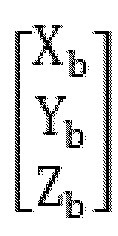

- S430: Based on the unit vectors in each direction after compensation, the compensated antenna beam direction is obtained.
- Optionally, the compensated antenna beam direction also refers to the specific azimuth and elevation directions, where the calculation method for azimuth direction is as follows:

- Wherein, AZb represents the azimuth direction.
- The calculation method for elevation direction is as follows:

- Wherein, ELb represents the elevation direction.
- In the antenna tracking method provided by this application example, the current attitude rotation matrix of the phased array antenna can be determined based on angle change information; based on the current attitude rotation matrix and the unit vector of the current beam direction, the unit vectors in each direction after compensation are determined; based on the unit vectors in each direction after compensation, the compensated antenna beam direction is obtained. Through calculations using the rotation matrix, more accurate unit vectors in each direction after compensation can be obtained, which in turn provides a more accurate compensated antenna beam direction, enhancing the precision of antenna tracking.
- Optionally, before determining the unit vectors in each direction after compensation based on the current attitude rotation matrix and the unit vector of the current beam direction, the method also comprises determining the unit vector of the current beam direction based on the elevation and azimuth angles under the current geographical coordinate system.
- The specific calculation formula is as follows:

- Based on the above formula, the unit vector of the current beam direction can be obtained.
- Optionally, determine the delay data for antenna tracking, including obtaining the delay data for antenna tracking in response to user input; or generating the delay data for antenna tracking based on the historical execution data of the antenna.
- It should be noted that based on different types of delay data, various methods can be employed to determine them. For instance, software system delay can be directly calculated using the antenna's control device, inertial navigation delay can be obtained by the user inputting historical data or trends, and instruction delay can be estimated based on historical execution data of instructions.
- Optionally, after obtaining each type of delay data through different methods, the sum of all delay data can be calculated, which yields the total delay, referred to as T in the aforementioned calculation formula.
- The following explains the specific implementation process of dynamic zero-bias calibration for the gyroscope in the antenna tracking method provided in this application example.
-
Figure 5 is another flowchart of the antenna tracking method provided in this application example. Refer toFigure 5 for dynamic zero-bias calibration of the gyroscope in the phased array antenna to obtain updated zero-bias data, including:
S510: When the phased array antenna is powered on, collect the gyroscope data of the phased array antenna. - Optionally, when the phased array antenna is powered on, collect N data points of the triaxial gyroscope in a stationary state, calculate the average values for each axis, and obtain the gyroscope data of the phased array antenna: gyro_bais_x, gyro _bais_y, gyro_bais_z; where gyro_bais_x is the x-axis data collected, gyro bais_y is the y-axis data collected, and gyro _bais_z is the z-axis data collected.
- S520: Calculate the average offset value of the gyroscope data.
- In subsequent operations, M segments of data can be collected, each containing L data points, with the total gyroscope data for M segments being N=M*L.
- When calculating the average offset value of the gyroscope data, each new data point collected is subtracted by the zero-bias base value and placed into a median digital filter, then the average offset value for that segment of data is calculated, with the specific formula as follows:


- Wherein, x, y, z are the values of the new data collected each time, and offset[0], offset[1], offset[2] are the average offset values for each axis.
- S530: Determine whether the average offset values meet the preset working conditions.
- Optionally, after obtaining the average offset values for each axis, the difference between the median filter and the average offsets can be calculated:


- Wherein, xdiff is the difference in average offset for the x-axis, ydiff is the difference in average offset for the y-axis, zdiff is the difference in average offset for the z-axis, filter[0]. median is the x-axis value in the median filter, filter[1].median is the y-axis value in the median filter, filter[2].median is the z-axis value in the median filter.
- After obtaining the aforementioned differences, it can be determined whether xdiff, ydiff, zdiff exceed the threshold; if so, they do not meet the preset working conditions; if not, they meet the preset working conditions.
- If met, S540: Update the gyroscope data based on the average offset values, obtaining the updated gyroscope zero-bias data.
- The update process is as follows:


- The updated gyroscope zero-bias data is as follows:



- The updated gyroscope zero-bias data are gyro_bais_x, gyro _bais_y, gyro_bais_z.
- If not met, S550: Recollect the gyroscope data of the phased array antenna and recalculate the average offset value, repeat the process until the average offset value meets the preset working conditions.
- Optionally, if the working conditions are not met, the data can be recollected and the average offset value recalculated, repeating the process until the average offset value meets the preset working conditions.
- In the antenna tracking method provided by this application example, when the phased array antenna is powered on, the gyroscope data of the phased array antenna can be collected; the average offset value of the gyroscope data is calculated; it is determined whether the average offset value meets the preset working conditions; if met, the gyroscope data is updated based on the average offset value, resulting in updated zero-bias data; if not met, the gyroscope data of the phased array antenna is recollected and the average offset value recalculated, repeating the process until the average offset value meets the preset working conditions. Through the determination of the average offset value, dynamic zero-bias calibration of the gyroscope can be achieved, thus obtaining more accurate zero-bias data.
- The following describes the devices, equipment, and storage media corresponding to the antenna tracking method provided by this application for execution. The specific implementation process and technical effects are referred to above and will not be reiterated here.
-
Figure 6 is a schematic diagram of the structure of the antenna tracking device provided by this application example. Refer toFigure 6 , the device comprises: acalibration module 610, adelay module 620, aprediction module 630, and acompensation module 640; -
Calibration module 610, used for dynamic zero-bias calibration of the gyroscope of the phased array antenna to obtain updated zero-bias data; -
Delay module 620, used to determine the delay data for antenna tracking, which comprises at least one of the following: software system delay, inertial navigation delay, instruction delay; -
Prediction module 630, used to predict the antenna beam direction based on the updated zero-bias data and delay data, obtaining the prediction results; -
Compensation module 640, used to compensate the antenna beam direction based on the prediction results, and to track the antenna according to the compensated antenna beam direction. - Optionally, the
prediction module 630 is specifically used to predict the angle change information of the phased array antenna based on the updated gyroscope zero-bias data and delay data, taking the angle change information as the prediction result, which comprises: heading angle change information, pitch angle change information, and roll angle change information. - Optionally, the
prediction module 630 is specifically used to determine the compensated antenna beam direction based on the angle change information, which comprises azimuth direction and elevation direction; antenna tracking is performed according to the compensated antenna beam direction. - Optionally, the
prediction module 630 is specifically used to determine the current attitude rotation matrix of the phased array antenna based on the angle change information; determine the compensated unit vectors in each direction based on the current attitude rotation matrix and the current beam direction unit vector; obtain the compensated antenna beam direction based on the compensated unit vectors in each direction. - Optionally, the
prediction module 630 is also used to determine the unit vector of the current beam direction based on the elevation and azimuth of the beam direction under the current geographic coordinate system. - Optionally, the
delay module 620 is specifically used to obtain the delay data for antenna tracking in response to user input; or, based on the historical execution data of the antenna, generate the delay data for antenna tracking. - Optionally, the
calibration module 610 is specifically used to collect gyroscope data of the phased array antenna when powered on; calculate the average offset value of the gyroscope data; determine whether the average offset value meets the preset working conditions; if met, update the gyroscope data based on the average offset value to obtain the updated gyroscope zero-bias data; if not met, recollect the gyroscope data of the phased array antenna and recalculate the average offset value, and repeat the process until the average offset value meets the preset working conditions. - The aforementioned device is used to execute the method provided in the previous examples, with similar implementation principles and technical effects, which are not further elaborated here.
- The aforementioned modules can be one or more integrated circuits configured to implement the above method, such as one or more Application Specific Integrated Circuits (ASIC), or one or more microprocessors, or one or more Field Programmable Gate Arrays (FPGA), etc. Furthermore, when one of the above modules is implemented by scheduling program code through a processing element, the processing element can be a general processor, such as a Central Processing Unit (CPU) or other processors that can invoke program code. Additionally, these modules can be integrated together to be implemented in the form of a system-on-a-chip (SOC).
-
Figure 7 is a schematic diagram of the computer device structure provided by this application example. Refer toFigure 7 , the computer device comprises:memory 710,processor 720, with a computer program stored inmemory 710 that runs onprocessor 720, which implements the steps of the antenna tracking method when executed byprocessor 720. - Optionally, the computer device can specifically be the control device for the aforementioned antenna, which can be a computer, a dedicated electronic device, or a controller integrated into the antenna, without specific limitations on the form, as long as it can implement the execution process of the aforementioned method.
- Another aspect of this application example provides a computer-readable storage medium, which stores a computer program that, when executed by a processor, implements the steps of the antenna tracking method.
- In several embodiments provided by this invention, it should be understood that the disclosed devices and methods can be implemented in other ways. For example, the device embodiments described above are merely illustrative. For instance, the division of units is just a logical functional division, and other division methods can be used in actual implementation, such as multiple units or components can be combined or integrated into another system, or some features can be omitted or not executed. Additionally, the coupling or direct coupling or communication connections shown or discussed can be indirect through interfaces, devices, or units, and can be electrical, mechanical, or other forms.
- The units described as separate components can be physically separate or not, and the parts displayed as units can be or may not be physical units, i.e., they can be located in one place or distributed across multiple network units. Parts or all of the units can be selected as needed to achieve the objectives of this embodiment.
- Furthermore, in various embodiments of this invention, the functional units can be integrated into a single processing unit, or each unit can exist physically separately, or two or more units can be integrated into one unit. The integrated units mentioned can be implemented in the form of hardware, or as a combination of hardware and software functional units.
- The integrated units implemented as software functional units can be stored in a computer-readable storage medium. These software functional units stored in a storage medium comprise several instructions to enable a computing device (such as a personal computer, server, or network device) or processor to execute parts of the methods of various embodiments of this invention. The aforementioned storage media comprise USB drives, portable hard drives, Read-Only Memory (ROM), Random Access Memory (RAM), disks, or optical discs, among other media capable of storing program code.
- The above only represents specific embodiments of this application, but the scope of protection of this application is not limited to these. Any technician familiar with this technical field can easily think of variations or substitutions within the technical scope disclosed by this application, and they should be comprised within the scope of protection of this application. Therefore, the scope of protection of this application should be determined by the scope of the claims.
- The above descriptions are merely preferred embodiments of this application and are not intended to limit this application. For technicians in this field, various modifications and changes can be made to this application. Any modifications, equivalent substitutions, and improvements made within the spirit and principles of this application should be comprised within the scope of protection of this application.
Claims (10)
- A method for antenna tracking, characterized in that it comprises:performing dynamic zero-bias calibration on the gyroscope of a phased array antenna to obtain updated gyroscope zero-bias data;determining the time delay data tracked by antenna, wherein the delay data comprises at least one of the following: software system delay, inertial navigation delay and instruction delay;predicting an antenna beam pointing direction according to the updated gyroscope zero-bias data and the time delay data and obtaining prediction results;performing compensation for the antenna beam pointing direction according to the prediction results and tracking the antenna according to the compensated antenna beam pointing direction.
- The method according to claim 1, characterized in that
predicting the antenna beam pointing direction according to the updated gyroscope zero-bias data and the time delay data and obtaining prediction results comprises:
predicting angle change information of the phased array antenna according to the updated gyroscope zero-bias data and the time delay data, and using the angle change information as the prediction results, wherein the angel change information includes: heading angle change information, pitch angle change information, and roll angle change information. - The method according to claim 2, characterized in that,
performing compensation for the antenna beam pointing direction according to the prediction results and tracking the antenna according to the compensated antenna beam pointing direction comprises:determining the compensated antenna beam pointing direction according to the angle change information, which comprises azimuth orientation and elevation orientation; andtracking the antenna according to the compensated antenna beam pointing direction. - The method according to claim 3, characterized in that determining the compensated antenna beam pointing direction according to the angle change information comprises:determining the current attitude rotation matrix of the phased array antenna according to the angle change information;determining the compensated unit vectors in each direction according to the current attitude rotation matrix and the unit vector of the current beam pointing direction; andobtaining the compensated antenna beam pointing direction according to the compensated unit vectors in each direction.
- The method according to claim 4, characterized in that, prior to determining the compensated unit vectors in each direction according to the current attitude rotation matrix and the unit vector of the current beam pointing direction, the method further comprises:
determining the unit vector of the current beam pointing direction according to the elevation angle and azimuth angle of the beam pointing direction under the current geographic coordinate system. - The method according to claim 1, characterized in that,
determining the delay data tracked by antenna comprises:obtaining the time delay data tracked by antenna in response to user input; or,generating the time delay data tracked by antenna according to the historical execution data of the antenna. - The method according to claim 1, characterized in that performing dynamic zero-bias calibration on a gyroscope of a phased array antenna to obtain updated gyroscope zero-bias data comprises:collecting gyroscope data from the phased array antenna when it is powered on;calculating the average offset value of the gyroscope data;determining whether the average offset value meets the preset working conditions;if it does, updating the gyroscope data based on the average offset value to obtain the updated gyroscope zero-bias data;if it does not, re-collecting the gyroscope data from the phased array antenna and recalculating the average offset value, repeating the process until the average offset value meets the preset working conditions.
- An antenna tracking device, characterized in that the device comprises:a calibration module, a delay module, a prediction module, and a compensation module, wherein the calibration module is used for dynamic zero-bias calibration of the gyroscope in the phased array antenna to obtain updated gyroscope zero-bias data;the delay module being used to determine the delay data for antenna tracking, which comprises at least one of the following: a software system delay, an inertial navigation delay and an instruction delay;the prediction module being used to predict the antenna beam pointing direction according to the updated gyroscope zero-bias data and the delay data, obtaining the prediction result; andthe compensation module being used to compensate the antenna beam pointing direction according to the prediction result and to track the antenna according to the compensated antenna beam pointing direction.
- A computer device, characterized in that it comprises:a memory, a processor, whereinthe memory stores a computer program that can run on the processor, and when the processor executes the computer program, it implements the steps of any one of claims 1 to 7.
- A computer storage medium, characterized in that, it stores a computer program, which, when executed by a processor, implements the steps of any one of the methods described in claims 1 to 7.
Applications Claiming Priority (2)
| Application Number | Priority Date | Filing Date | Title |
|---|---|---|---|
| CN202210604321.7A CN117199814B (en) | 2022-05-30 | 2022-05-30 | An antenna tracking method, apparatus, device, and storage medium |
| PCT/CN2022/104097 WO2023231142A1 (en) | 2022-05-30 | 2022-07-06 | Antenna tracking method and apparatus, and device and storage medium |
Publications (2)
| Publication Number | Publication Date |
|---|---|
| EP4518031A1 true EP4518031A1 (en) | 2025-03-05 |
| EP4518031A4 EP4518031A4 (en) | 2025-08-27 |
Family
ID=88983784
Family Applications (1)
| Application Number | Title | Priority Date | Filing Date |
|---|---|---|---|
| EP22944457.5A Pending EP4518031A4 (en) | 2022-05-30 | 2022-07-06 | Antenna tracking method and device, as well as device and storage medium |
Country Status (3)
| Country | Link |
|---|---|
| EP (1) | EP4518031A4 (en) |
| CN (1) | CN117199814B (en) |
| WO (1) | WO2023231142A1 (en) |
Families Citing this family (5)
| Publication number | Priority date | Publication date | Assignee | Title |
|---|---|---|---|---|
| CN117978239B (en) * | 2024-01-26 | 2024-07-30 | 中国人民解放军军事科学院系统工程研究院 | Shipborne satellite network terminal station of high-flux satellite communication system |
| CN119064960B (en) * | 2024-11-04 | 2025-01-03 | 广东省测绘产品质量监督检验中心 | Beidou navigation antenna calibration system based on multiple knowledge bodies |
| CN119544061B (en) * | 2024-11-07 | 2025-11-18 | 上海卫星工程研究所 | Method and System for Calculating Attitude Deviation Compensation in Inter-Satellite Laser Communication |
| CN119253271A (en) * | 2024-12-02 | 2025-01-03 | 西安交通大学 | A phased array antenna with adaptive beam pointing function |
| CN119805506B (en) * | 2025-03-12 | 2026-01-27 | 东方空间技术(山东)有限公司 | Automatic debugging device and method for portable satellite measurement and control antenna |
Family Cites Families (15)
| Publication number | Priority date | Publication date | Assignee | Title |
|---|---|---|---|---|
| JP3186533B2 (en) * | 1995-08-30 | 2001-07-11 | 松下電工株式会社 | Tracking antenna device |
| JP3709610B2 (en) * | 1996-05-24 | 2005-10-26 | トヨタ自動車株式会社 | In-vehicle satellite signal receiver |
| JP3589990B2 (en) * | 2001-02-08 | 2004-11-17 | 三菱電機株式会社 | Antenna control method and antenna control device |
| JP4191588B2 (en) * | 2003-12-19 | 2008-12-03 | 三菱電機株式会社 | Satellite tracking antenna controller |
| CN103022692B (en) * | 2012-11-14 | 2014-09-17 | 广东隆伏通讯设备有限公司 | Communication-in-motion satellite pointing, capturing and tracking method and system thereof |
| CN105045298B (en) * | 2015-08-04 | 2017-11-07 | 北京航天控制仪器研究所 | A kind of antenna for satellite communication in motion tracking and controlling method based on inertial navigation system Measurement delay |
| CN105444762B (en) * | 2015-11-10 | 2018-02-06 | 北京航天控制仪器研究所 | A kind of ins error rapid correction method for airborne communication in moving |
| CN106441361B (en) * | 2016-09-26 | 2019-07-16 | 西安坤蓝电子技术有限公司 | A Dynamic Compensation Method for Angular Rate Gyro Bias of Mobile VSAT Antenna |
| US10756428B2 (en) * | 2017-02-13 | 2020-08-25 | General Dynamics Mission Systems, Inc. | Systems and methods for inertial navigation system to RF line-of sight alignment calibration |
| CN107483121B (en) * | 2017-06-22 | 2020-07-14 | 山东航天电子技术研究所 | Signal occlusion detection and recovery method for a pass-in-motion antenna |
| CN107492717B (en) * | 2017-06-22 | 2020-03-17 | 山东航天电子技术研究所 | Inertial navigation course correction method for communication-in-moving antenna cosine scanning |
| CN107785663B (en) * | 2017-10-10 | 2018-10-12 | 深圳市华讯方舟空间信息产业科技有限公司 | antenna beam attitude control method and system |
| CN109443385B (en) * | 2018-11-13 | 2022-07-29 | 中国兵器装备集团自动化研究所有限公司 | Inertial navigation installation error automatic calibration method of communication-in-moving antenna |
| EP4022799B1 (en) * | 2019-11-12 | 2023-11-08 | Viasat, Inc. | Yaw drift compensation for pointing an antenna |
| CN110824524B (en) * | 2019-11-13 | 2021-10-26 | 西安通航装备科技开发有限公司 | Satellite video transmission system based on airborne Ka wave band |
-
2022
- 2022-05-30 CN CN202210604321.7A patent/CN117199814B/en active Active
- 2022-07-06 WO PCT/CN2022/104097 patent/WO2023231142A1/en not_active Ceased
- 2022-07-06 EP EP22944457.5A patent/EP4518031A4/en active Pending
Also Published As
| Publication number | Publication date |
|---|---|
| CN117199814B (en) | 2026-04-24 |
| EP4518031A4 (en) | 2025-08-27 |
| WO2023231142A1 (en) | 2023-12-07 |
| CN117199814A (en) | 2023-12-08 |
Similar Documents
| Publication | Publication Date | Title |
|---|---|---|
| US12366666B2 (en) | Systems and methods for reduced-outlier satellite positioning | |
| CN117199814B (en) | An antenna tracking method, apparatus, device, and storage medium | |
| US11906653B2 (en) | System and method of calibrating a radar rotatable antenna system | |
| AU2011258700B2 (en) | Determining spatial orientation information of a body from multiple electromagnetic signals | |
| EP3693759B1 (en) | System and method for tracking motion of target in indoor environment | |
| US11885894B2 (en) | 2022-large-scale cooperative positioning with Global Navigation Satellite System | |
| US11573329B2 (en) | Modeling effects of structures on global-positioning system localization | |
| US11620846B2 (en) | Data processing method for multi-sensor fusion, positioning apparatus and virtual reality device | |
| CN119533482A (en) | A ship docking positioning method and system based on multi-source positioning data fusion | |
| US20240410977A1 (en) | Sensor control system, method, and program | |
| JP7235357B2 (en) | POSITIONING ASSISTANCE DEVICE, POSITIONING ASSISTANCE METHOD, AND PROGRAM | |
| CN116009044A (en) | A single-antenna ship attitude measurement method, device and electronic equipment | |
| JP4400330B2 (en) | Position detection apparatus and position detection method | |
| Wang et al. | Robust GNSS/INS hybrid integration based on multi-state validation of GNSS measurements | |
| RU2408917C1 (en) | Orientation system of communication station antenna | |
| CN113804194A (en) | Positioning method, device and equipment of driving equipment and storage medium | |
| CN112698374A (en) | Multi-frequency dual-antenna vehicle-mounted attitude measurement method and device based on BDS-3/magnetometer | |
| WO2021044865A1 (en) | Positioning assistance device, positioning assistance method, and computer-readable recording medium | |
| CN116299266B (en) | Method and device for calculating azimuth ambiguity of spaceborne synthetic aperture radar | |
| CN118314771B (en) | Ship collision risk assessment method and system | |
| CN120292959A (en) | Attitude angle control system and method for launch vehicle | |
| KR20240080778A (en) | Velocity estimation of unmanned vehicle using radar | |
| CN115343730A (en) | GNSS antenna external parameter determination method, device and computer readable storage medium | |
| JP2022133209A (en) | Error detection device, error detection method, and error detection program | |
| Han et al. | Design of Ship Tracking Space Situational Awareness Guidance System |
Legal Events
| Date | Code | Title | Description |
|---|---|---|---|
| STAA | Information on the status of an ep patent application or granted ep patent |
Free format text: STATUS: THE INTERNATIONAL PUBLICATION HAS BEEN MADE |
|
| PUAI | Public reference made under article 153(3) epc to a published international application that has entered the european phase |
Free format text: ORIGINAL CODE: 0009012 |
|
| STAA | Information on the status of an ep patent application or granted ep patent |
Free format text: STATUS: REQUEST FOR EXAMINATION WAS MADE |
|
| 17P | Request for examination filed |
Effective date: 20241127 |
|
| AK | Designated contracting states |
Kind code of ref document: A1 Designated state(s): AL AT BE BG CH CY CZ DE DK EE ES FI FR GB GR HR HU IE IS IT LI LT LU LV MC MK MT NL NO PL PT RO RS SE SI SK SM TR |
|
| A4 | Supplementary search report drawn up and despatched |
Effective date: 20250728 |
|
| RIC1 | Information provided on ipc code assigned before grant |
Ipc: H01Q 3/08 20060101AFI20250722BHEP Ipc: H01Q 3/02 20060101ALI20250722BHEP Ipc: H04B 7/185 20060101ALI20250722BHEP |
|
| DAV | Request for validation of the european patent (deleted) | ||
| DAX | Request for extension of the european patent (deleted) |