EP4517978A1 - Battery housing, battery cell, battery, and electrical apparatus - Google Patents
Battery housing, battery cell, battery, and electrical apparatus Download PDFInfo
- Publication number
- EP4517978A1 EP4517978A1 EP23876702.4A EP23876702A EP4517978A1 EP 4517978 A1 EP4517978 A1 EP 4517978A1 EP 23876702 A EP23876702 A EP 23876702A EP 4517978 A1 EP4517978 A1 EP 4517978A1
- Authority
- EP
- European Patent Office
- Prior art keywords
- battery
- wall
- arc
- bottom wall
- shaped surface
- Prior art date
- Legal status (The legal status is an assumption and is not a legal conclusion. Google has not performed a legal analysis and makes no representation as to the accuracy of the status listed.)
- Pending
Links
Images




Classifications
-
- H—ELECTRICITY
- H01—ELECTRIC ELEMENTS
- H01M—PROCESSES OR MEANS, e.g. BATTERIES, FOR THE DIRECT CONVERSION OF CHEMICAL ENERGY INTO ELECTRICAL ENERGY
- H01M50/00—Constructional details or processes of manufacture of the non-active parts of electrochemical cells other than fuel cells, e.g. hybrid cells
- H01M50/10—Primary casings; Jackets or wrappings
- H01M50/102—Primary casings; Jackets or wrappings characterised by their shape or physical structure
- H01M50/103—Primary casings; Jackets or wrappings characterised by their shape or physical structure prismatic or rectangular
-
- H—ELECTRICITY
- H01—ELECTRIC ELEMENTS
- H01M—PROCESSES OR MEANS, e.g. BATTERIES, FOR THE DIRECT CONVERSION OF CHEMICAL ENERGY INTO ELECTRICAL ENERGY
- H01M50/00—Constructional details or processes of manufacture of the non-active parts of electrochemical cells other than fuel cells, e.g. hybrid cells
- H01M50/50—Current conducting connections for cells or batteries
- H01M50/572—Means for preventing undesired use or discharge
- H01M50/584—Means for preventing undesired use or discharge for preventing incorrect connections inside or outside the batteries
- H01M50/586—Means for preventing undesired use or discharge for preventing incorrect connections inside or outside the batteries inside the batteries, e.g. incorrect connections of electrodes
-
- H—ELECTRICITY
- H01—ELECTRIC ELEMENTS
- H01M—PROCESSES OR MEANS, e.g. BATTERIES, FOR THE DIRECT CONVERSION OF CHEMICAL ENERGY INTO ELECTRICAL ENERGY
- H01M50/00—Constructional details or processes of manufacture of the non-active parts of electrochemical cells other than fuel cells, e.g. hybrid cells
- H01M50/50—Current conducting connections for cells or batteries
- H01M50/572—Means for preventing undesired use or discharge
- H01M50/584—Means for preventing undesired use or discharge for preventing incorrect connections inside or outside the batteries
- H01M50/59—Means for preventing undesired use or discharge for preventing incorrect connections inside or outside the batteries characterised by the protection means
- H01M50/593—Spacers; Insulating plates
-
- H—ELECTRICITY
- H01—ELECTRIC ELEMENTS
- H01M—PROCESSES OR MEANS, e.g. BATTERIES, FOR THE DIRECT CONVERSION OF CHEMICAL ENERGY INTO ELECTRICAL ENERGY
- H01M50/00—Constructional details or processes of manufacture of the non-active parts of electrochemical cells other than fuel cells, e.g. hybrid cells
- H01M50/20—Mountings; Secondary casings or frames; Racks, modules or packs; Suspension devices; Shock absorbers; Transport or carrying devices; Holders
- H01M50/204—Racks, modules or packs for multiple batteries or multiple cells
- H01M50/207—Racks, modules or packs for multiple batteries or multiple cells characterised by their shape
- H01M50/209—Racks, modules or packs for multiple batteries or multiple cells characterised by their shape adapted for prismatic or rectangular cells
-
- Y—GENERAL TAGGING OF NEW TECHNOLOGICAL DEVELOPMENTS; GENERAL TAGGING OF CROSS-SECTIONAL TECHNOLOGIES SPANNING OVER SEVERAL SECTIONS OF THE IPC; TECHNICAL SUBJECTS COVERED BY FORMER USPC CROSS-REFERENCE ART COLLECTIONS [XRACs] AND DIGESTS
- Y02—TECHNOLOGIES OR APPLICATIONS FOR MITIGATION OR ADAPTATION AGAINST CLIMATE CHANGE
- Y02E—REDUCTION OF GREENHOUSE GAS [GHG] EMISSIONS, RELATED TO ENERGY GENERATION, TRANSMISSION OR DISTRIBUTION
- Y02E60/00—Enabling technologies; Technologies with a potential or indirect contribution to GHG emissions mitigation
- Y02E60/10—Energy storage using batteries
Definitions
- the present application relates to the technical field of batteries, and in particular, to a battery shell, a battery cell, a battery, and an electrical device.
- a battery includes a battery shell and an electrode core.
- the electrode core When assembling the battery, the electrode core is usually placed in the battery shell, and the electrode core is in contact with the inner wall of the battery shell.
- the traditional battery has great safety hazards.
- a battery shell has an accommodation cavity, the accommodation cavity includes a bearing bottom wall, a plurality of side walls and inner corner portions, and each inner corner portion is connected between the bearing bottom wall and the corresponding side walls, where the inner corner portions are provided with receding grooves in a concave manner.
- an electrode core can be placed in the accommodation cavity and placed on the bearing bottom wall, bottom corner portions of the electrode core placed on the bearing bottom wall are located on the upper side of the bearing bottom wall, and the receding grooves are formed in the inner corner portions between the bearing bottom wall and the side walls and disposed in a concave manner. It is understood that the bottom corner portions of the electrode core can be spaced apart from the groove walls of the receding grooves.
- the bottom corner portions of the electrode core can be well prevented from being in contact with the inner corner portions between the bearing bottom wall and the side walls, that is, the bottom corner portions can not be in contact with the battery shell, and it is avoided that corresponding extrusion pressure is generated on the electrode core due to the contact between the battery shell and the bottom corner portions, so that the use of the receding grooves can effectively improve the safety of a battery.
- a first preset interval D 1 is provided between the very bottom of the groove wall of each receding groove and the bearing bottom wall. This setting not only facilitates the processing of the receding grooves, but also ensures an internal space of the battery shell, and thus ensures the energy density of the battery cell.
- the first preset interval D 1 is greater than or equal to 0.3 millimeter (mm).
- the first preset interval D 1 is set to be greater than or equal to 0.3 millimeter (mm), which not only facilitates the processing of the receding grooves, but also ensures the energy density of the battery cell.
- the groove wall of each receding groove is in rounded corner connection with the bearing bottom wall and the corresponding side wall respectively.
- the stress concentration can be avoided at the connection between the receding grooves and the bearing bottom wall, and at the connection between the receding grooves and the corresponding side walls, which is conducive to improving the strength of the battery shell.
- the groove wall of each receding groove includes a first arc-shaped surface tangent to the bearing bottom wall and a second arc-shaped surface tangent to the corresponding side wall.
- the use of the first arc-shaped surface and the second arc-shaped surface can well avoid the stress concentration at the connection between the receding grooves and the bearing bottom wall, and at the connection between the receding grooves and the corresponding side wall, which is conducive to improving the strength of the battery shell.
- the first arc-shaped surface and the second arc-shaped surface are directly connected. Therefore, this setting facilitates the processing of the receding grooves and is conducive to improving the processing efficiency of the battery shell.
- each receding groove further includes a third arc-shaped surface connected between the first arc-shaped surface and the second arc-shaped surface, and the third arc-shaped surface is disposed tangent to the first arc-shaped surface and the second arc-shaped surface respectively.
- the stress concentration can be avoided at the connection between the receding grooves and the bearing bottom wall, and at the connection between the receding grooves and the corresponding side walls, the stress concentration can also be avoided at the groove walls of the receding grooves, and the strength of the battery shell can be better improved.
- the groove wall of each receding groove further includes a straight wall surface, and along the direction perpendicular to the bearing bottom wall, the straight wall surface is spaced apart from the bearing bottom wall, and the straight wall surface is tangent to the first arc-shaped surface and the second arc-shaped surface respectively.
- the straight wall surface is disposed parallel with the bearing bottom wall.
- a second preset interval D 2 is provided between the farthest point on an edge of the first arc-shaped surface tangent to the bearing bottom wall and the side wall. It can not only ensure the energy density of the battery cell, but also ensure that there is a certain interval between the peripheral wall of the electrode core and the side walls, and avoid excessive bearing pressure.
- the second preset interval D 2 is greater than or equal to 0.5 millimeter (mm).
- a battery cell includes the foregoing battery shell and an electrode core, and the electrode core has bottom corner portions, where the electrode core is accommodated in an accommodation cavity and placed on a bearing bottom wall, and the bottom corner portions are separated from groove walls of receding grooves.
- the electrode core includes an electrode assembly and an electrical isolation part, and the electrode assembly is electrically isolated from the battery shell through the electrical isolation part.
- the bottom corner portions include first corner portions disposed on the electrode assembly and second corner portions disposed on the electrical isolation part.
- the electrode assembly has a bottom surface and a plurality of side surfaces, where the first corner portions are connected between the bottom surface and the corresponding side surfaces.
- a battery including the foregoing battery cell.
- an electrical device including the foregoing battery.
- a direction or a positional relationship indicated by the terms such as “center”, “longitudinal”, “transverse”, “length”, “width”, “thickness”, “up”, “down”, “before”, “after”, “left”, “right”, “vertical”, “horizontal”, “top”, “bottom”, “in”, “out”, “clockwise”, “counterclockwise”, “axial”, “radial”, and “circumferential” is a direction or positional relationship based on the illustration in the drawings, and is merely intended for ease or brevity of description of the present application, but not intended to indicate or imply that the mentioned device or component must be located in the specified direction or constructed or operated in the specified direction. Therefore, such terms are not intended as a limitation on the present application.
- first and second are used merely for descriptive purposes but are not to be construed as indicating or implying relative importance or implicitly specifying the quantity of technical features indicated. Therefore, a feature defined with “first” or “second” may explicitly or implicitly include at least one of the features.
- a plurality of means at least two, for example, two, three, etc.
- the terms such as “mount”, “concatenate”, “connect” and “fix” shall be understood broadly, for example, mean a fixed connection, a detachable connection, or a one-piece configuration; or mean a mechanical connection or an electrical connection; or mean a direct connection or an indirect connection implemented through an intermediary; or mean internal communication between two components or interaction between two components, unless otherwise expressly defined.
- a first feature being “on” or “under” a second feature may be that the first feature is in direct contact with the second feature, or the first feature is in indirect contact with the second feature through an intermediary.
- a first feature being “on”, “above”, or “over” a second feature may mean that the first feature is directly above or obliquely above the second feature, or just mean that the first feature is at an altitude higher than the second feature.
- a first feature being “under”, “below”, or “beneath” a second feature may mean that the first feature is exactly under or obliquely under the second feature, or just mean that the first feature is at an altitude lower than the second feature.
- a battery includes a battery shell, an electrode core and a top cover.
- the electrode core is usually placed in the battery shell, and then the top cover covers the battery shell.
- the traditional battery has great safety hazards.
- Bottom rounded corners are usually designed at corners of the battery shell of the traditional battery, resulting in the bottom rounded corner of the battery shell is easy to contact with the bottom corner of the battery cell, which will produce extrusion pressure on the electrode core, resulting in great safety hazards of the traditional battery.
- the present application designs a battery shell.
- the battery shell is provided with receding grooves used for receding bottom corner portions of an electrode core, so as to prevent the bottom corner portions of the electrode core from being in contact with the battery shell, which can effectively improve the safety of a battery.
- a battery shell, a battery cell and/or a battery disclosed in embodiments of the present application may be used in, but is not limited to be used in, an electrical device such as a vehicle, watercraft, or aircraft.
- the electrical device may be, but is not limited to, a mobile phone, a tablet, a laptop computer, an electric toy, an electric tool, an electric power cart, an electric vehicle, a ship, a spacecraft, or the like.
- the electric toy may include stationary or mobile electric toys, such as a game console, an electric car toy, an electric ship toy, an electric airplane toy, and the like.
- the spacecraft may include an airplane, a rocket, a space shuttle, a spaceship, and the like.
- a power supply system consisting of the electrical device with the battery cells and/or batteries disclosed in the present application may be used so as to facilitate the supply of electric drive to the electrical device.
- FIG. 1 is a schematic structural diagram of a vehicle 1 according to some embodiments of the present application.
- the vehicle 1 may be an oil-fueled vehicle, a natural gas vehicle, or a new energy vehicle.
- the new energy vehicle may be a battery electric vehicle, a hybrid electric vehicle, a range-extended electric vehicle, or the like.
- a battery 10 is disposed inside the vehicle 1.
- the battery 10 may be disposed at the bottom, front, or rear of the vehicle 1.
- the battery 10 may be used for supplying power to the vehicle 1.
- the battery 10 may serve as an operating power supply of the vehicle 1.
- the vehicle 1 may further include a motor 20 and a controller 30.
- the controller 30 is used for controlling the battery 10 to supply power to the motor 20, for example, to meet the operating power requirements of the vehicle 1 in start, navigation and running.
- the battery 10 serves not only as an operating power supply of the vehicle 1, but may also serve as a driving power supply of the vehicle 1 to provide driving power for the vehicle 1 in place of or partly in place of fuel oil or natural gas.
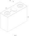
- FIG. 2 is a schematic structural diagram of a battery cell 100 according to an embodiment of the present application.
- FIG. 3 is a schematic exploded diagram of the battery cell 100 according to an embodiment of the present application.
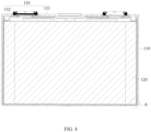
- FIG. 4 is a sectional diagram of the battery cell 100 according to an embodiment of the present application.
- the battery cell 100 provided by an embodiment of the present application includes a battery shell 110.
- the battery cell 100 further includes an electrode core 120, and the electrode core 120 can be accommodated in the battery shell 110.
- the bearing bottom wall 1111 refers to a part of the groove wall of the accommodation cavity 111 used for bearing the electrode core 120, the bearing bottom wall 1111 is in contact with the bottom of the electrode core 120, and the bearing bottom wall 1111 is used for bearing the electrode core 120.
- the receding grooves 112 are formed at the inner corner portions between the bearing bottom wall 1111 and the corresponding side walls 1112 and are concave, that is, the receding grooves 112 ae formed at the connections between the bearing bottom wall 1111 and the corresponding side walls 1112 and are concave, so as to be used for receding the bottom corner portions 1201 of the electrode core 120.
- the accommodation cavity 111 also includes a first opening 1113 opposite and spaced apart from the bearing bottom wall 1111, and the receding grooves 112 are concave in a direction of the first opening 1113 towards the bearing bottom wall 1111 with respect to the bearing bottom wall 1111.
- the electrode core 120 can be placed in the accommodation cavity 111 and placed on the bearing bottom wall 1111, the bottom corner portions 1201 of the electrode core 120 placed on the bearing bottom wall 1111 are located on the upper side of the bearing bottom wall 1111, and the receding grooves 112 are formed in the inner corner portions between the bearing bottom wall 1111 and the side walls 1112 and disposed in a concave manner. It is understood that the bottom corner portions 1201 of the electrode core 120 can extend into the receding grooves 112 and can be spaced apart from the groove walls of the receding grooves 112.
- the bottom corner portions 1201 of the electrode core 120 can be well prevented from being in contact with the inner corner portions between the bearing bottom wall 1111 and the side walls 1112, that is, the bottom corner portions 1201 can not be in contact with the battery shell 110, and it is avoided that corresponding extrusion pressure is generated on the electrode core 120 due to the contact between the battery shell 110 and the bottom corner portions 1201, so that the use of the receding grooves 112 can effectively improve the safety of the battery 10.
- the inner corner portions are conveniently formed between the bearing bottom wall 1111 and the corresponding side walls 1112, so as to form the corresponding receding grooves 112.
- a first preset interval D 1 is provided between the very bottom of the groove wall of each receding groove 112 and the bearing bottom wall 1111.
- the first preset interval D 1 is greater than or equal to 0.3 millimeter (mm).
- the first preset interval D 1 is set to be greater than or equal to 0.3 millimeter (mm), which not only facilitates the processing of the receding grooves 112, but also ensures the energy density of the battery cell 100.
- each receding groove 112 is in rounded corner connection with the bearing bottom wall 1111 and the corresponding side wall 1112 respectively.
- each receding groove 112 is in an arc transition to the bearing bottom wall 1111 and the corresponding side wall 1112, and the stress concentration can be avoided at the connection between the receding grooves 112 and the bearing bottom wall 1111, and at the connection between the receding grooves 112 and the corresponding side walls 1112, which is conducive to improving the strength of the battery shell 110.
- each receding groove 112 includes a first arc-shaped surface 1121 tangent to the bearing bottom wall 1111 and a second arc-shaped surface 1122 tangent to the corresponding side wall 1112.
- the side that is of the first arc-shaped surface 1121 and that is away from the bearing bottom wall 1111 may be directly connected with the side that is of the second arc-shaped surface 1122 and that is away from the corresponding side wall 1112, and the side that is of the first arc-shaped surface 1121 and that is away from the bearing bottom wall 1111 may also be indirectly connected with the side that is of the second arc-shaped surface 1122 and that is away from the corresponding side wall 1112, which is not specifically limited herein.
- the first arc-shaped surfaces 1121 tangent to the bearing bottom wall 1111 and the second arc-shaped surfaces 1122 tangent to the corresponding side walls 1112 can well avoid the stress concentration at the connection between the receding grooves 112 and the bearing bottom wall 1111, and at the connection between the receding grooves 112 and the corresponding side walls 1112, which is conducive to improving the strength of the battery shell 110.
- each receding groove 112 further includes a third arc-shaped surface 1123 connected between the first arc-shaped surface 1121 and the second arc-shaped surface 1122, and the third arc-shaped surface 1123 is disposed tangent to the first arc-shaped surface 1121 and the second arc-shaped surface 1122 respectively.
- the stress concentration can be avoided at the connection between the receding grooves 112 and the bearing bottom wall 1111, and at the connection between the receding grooves 112 and the corresponding side walls 1112, the stress concentration can also be avoided at the groove walls of the receding grooves 112, and the strength of the battery shell 110 can be better improved.
- the groove wall of each receding groove 112 further includes a straight wall surface 1124, along the direction perpendicular to the bearing bottom wall 1111, the straight wall surface 1124 is spaced apart from the bearing bottom wall 1111, and the straight wall surface 1124 is tangent to the first arc-shaped surface 1121 and the second arc-shaped surface 1122 respectively.
- the straight wall surface 1124 is roughly planar, may be parallel with the bearing bottom wall 1111, and may also be disposed at an angle with the bearing bottom wall 1111.
- the straight wall surface 1124 is spaced apart from the bearing bottom wall 1111, and the straight wall surface 1124 is tangent to the first arc-shaped surface 1121 and the second arc-shaped surface 1122 respectively. It is understood that the receding grooves 112 are concave in the direction of the bearing bottom wall 1111 towards the straight wall surfaces 1124 with respect to the bearing bottom wall 1111. In this way, the bottom corner portions 1201 of the electrode core 120 placed on the bearing bottom wall 1111 can be well spaced apart from the groove walls of the receding grooves 112, so that it is avoided that corresponding extrusion pressure is generated on the electrode core 120 due to the contact between the battery shell 110 and the bottom corner portions 1201, and the safety of the battery 10 can be effectively improved.
- the straight wall surface 1124 is parallel with the bearing bottom wall 1111.
- the bottom corner portions 1201 of the electrode core 120 placed on the bearing bottom wall 1111 can be well spaced apart from the groove walls of the receding grooves 112, and the safety of the battery 10 can be better improved.
- the third arc-shaped surface 1123 is disposed between the straight wall surface 1124 and the first arc-shaped surface 1121.
- the stress concentration can be avoided at the groove walls of the receding grooves 112 and the strength of the battery shell 110 can be well improved.
- a second preset interval D 2 is provided between the farthest point on an edge of the first arc-shaped surface 1121 tangent to the bearing bottom wall 1111 and the side wall 1112.
- the side wall 1112 is the corresponding side wall 1112 of the receding groove 112 where the first arc-shaped surface 1121 is located.
- the second preset interval D 2 is greater than or equal to 0.5 millimeter (mm).
- the second preset interval D 2 is set to be greater than or equal to 0.5 millimeter (mm), which can not only ensure the energy density of the battery cell 100, but also ensure that there is a certain interval between the peripheral wall of the electrode core 120 and the side walls 1112, and avoid excessive bearing pressure.
- the accommodation cavity 111 includes a bearing bottom wall 1111, a plurality of side walls 1112 and inner corner portions, and each inner corner portion is disposed between the bearing bottom wall 1111 and the corresponding side walls 1112, to connect the bearing bottom wall 1111 and the two adjacent side walls 1112, where the inner corner portions are provided with receding grooves 112 in a concave manner.
- the groove wall of each receding groove 112 is in rounded corner connection with the bearing bottom wall 1111 and the corresponding side wall 1112 respectively.
- the use of the receding grooves 112 can effectively improve the safety of the battery 10, and can also avoid the stress concentration at the connection between the receding grooves 112 and the bearing bottom wall 1111, and at the connection between the receding grooves 112 and the corresponding side walls 1112, which is conducive to improving the strength of the battery shell 110.
- a battery cell 100 provided by an embodiment of the present application includes the foregoing battery shell 110 and an electrode core 120, where the electrode core 120 has bottom corner portions 1201, the electrode core 120 is accommodated in the accommodation cavity 111 and placed on the bearing bottom wall 1111, and the bottom corner portions 1201 are separated from the groove walls of the receding grooves 112.
- the electrode core 120 includes an electrode assembly 121 and an electrical isolation part 122, and the electrode assembly 121 is electrically isolated from the battery shell 110 through the electrical isolation part 122.
- the bottom corner portions 1201 include first corner portions 1202 disposed on the electrode assembly 121 and second corner portions 1205 disposed on the electrical isolation part 122.
- the electrical isolation part 122 refers to a part that can electrically isolate the electrode assembly 121 from the battery shell 110, and may be made of an insulating material.
- the electrical isolation part 122 may wrap the bottom and peripheral wall of the electrode assembly 121 so as to electrically isolate the electrode assembly 121 from the battery shell 110.
- the electrical isolation part 122 can electrically isolate the electrode assembly 121 from the battery shell 110, which is conducive to improving the safety of the battery cell 100.
- the electrode assembly 121 has a bottom surface 1203 and a plurality of side surfaces 1204, where the first corner portions 1202 are connected between the bottom surface 1203 and the corresponding side surfaces 1204.
- Each first corner portion 1202 is connected between the bottom surface 1203 and the corresponding two adjacent side surfaces 1204, located in the receding groove 112 and separated from the groove wall of the receding groove 112 to avoid the contact between the first corner portion 1202 and the battery shell 110, which can improve the safety of the battery cell 100.
- the electrical isolation part 122 defines an electrical cavity having a second opening 1221 at one end and used for receiving the electrode assembly 121, the electrode assembly 121 is disposed in the electrical cavity through the second opening 1221, and the second corner portions 1205 surround the first corner portions 1202.
- the second corner portions 1205 are located at the bottom corner parts of the electrical isolation part 122 and not in contact with the bearing bottom wall 1111.
- the electrical isolation part 122 is provided with a notch 1206 which communicates with the electrical cavity and the accommodation cavity 111 respectively, and the notch 1206 is adjacent to the second corner portion 1205, thus, an electrolyte solution in the electrical cavity can flow into the accommodation cavity 111 through the notch 1206, which can improve the volume of the electrolyte solution to a certain extent, and is conducive to improving the energy density of the battery cell 100.
- the electrical isolation part 122 includes a bottom plate portion 1222 and a side wall portion 1223 connected to the bottom plate portion 1222, and the notch 1206 is located between the bottom plate portion 1222 and the side wall portion 1223.
- the side wall portion 1223 and the bottom plate portion 1222 are integrally formed to improve the strength of the electrical isolation part 122.
- the side wall portion 1223 is bent relative to the bottom plate portion 1222, and the side wall portion 1223 surrounds the peripheral wall of the electrode assembly 121, so that the electrode assembly 121 is placed on the bearing bottom wall 1111 through the bottom plate portion 1222 of the electrical isolation part 122, the bottom of the electrode assembly 121 is electrically isolated from the battery shell 110 through the bottom plate portion 1222, and the peripheral wall of the electrode assembly 121 is electrically isolated from the battery shell 110 through the side wall portion 1223.
- the accommodation cavity 111 also includes a first opening 1113 spaced apart from the bearing bottom wall 1111 along the axis direction of the accommodation cavity 111
- the battery cell 100 also includes a top cover 130
- the top cover 130 includes a top cover body 131 and at least one protrusion portion 132 (as shown in FIG. 3 ), where the top cover body 131 is connected to one end of the battery shell 110 to close the first opening 1113 of the accommodation cavity 111.
- At least one protrusion portion 132 is arranged on the side of the top cover body 131 towards the accommodation cavity 111 and is connected to one end of the electrical isolation part 122 provided with the second opening 1221.
- One or more protrusion portions 132 may be provided, which is not specifically limited herein.
- the top cover body 131 of the top cover 130 is connected to one end of the battery shell 110 to close the first opening 1113 of the accommodation cavity 111, and at least one protrusion portion 132 of the top cover 130 is connected to one end of the electrical isolation part 122 provided with the second opening 1221, which is conducive to improving the overall strength and stability of the battery cell 100.
- a battery 10 provided by an embodiment of the present application includes the foregoing battery cell 100.
- An electrical device provided by an embodiment of the present application includes the foregoing battery 10.
Landscapes
- Chemical & Material Sciences (AREA)
- Chemical Kinetics & Catalysis (AREA)
- Electrochemistry (AREA)
- General Chemical & Material Sciences (AREA)
- Sealing Battery Cases Or Jackets (AREA)
- Battery Mounting, Suspending (AREA)
Abstract
Description
- The present application claims priority to
Chinese Patent Application No. 202222686468.3, filed on October 12, 2022 - The present application relates to the technical field of batteries, and in particular, to a battery shell, a battery cell, a battery, and an electrical device.
- A battery includes a battery shell and an electrode core. When assembling the battery, the electrode core is usually placed in the battery shell, and the electrode core is in contact with the inner wall of the battery shell. However, the traditional battery has great safety hazards.
- In view of the situation above, it is necessary to provide a battery shell, a battery cell, a battery, and an electrical device to solve the problem of great safety hazards in a traditional battery.
- According to a first aspect of the present application, a battery shell is provided. The battery shell has an accommodation cavity, the accommodation cavity includes a bearing bottom wall, a plurality of side walls and inner corner portions, and each inner corner portion is connected between the bearing bottom wall and the corresponding side walls, where the inner corner portions are provided with receding grooves in a concave manner.
- In the technical solution of the present application, an electrode core can be placed in the accommodation cavity and placed on the bearing bottom wall, bottom corner portions of the electrode core placed on the bearing bottom wall are located on the upper side of the bearing bottom wall, and the receding grooves are formed in the inner corner portions between the bearing bottom wall and the side walls and disposed in a concave manner. It is understood that the bottom corner portions of the electrode core can be spaced apart from the groove walls of the receding grooves. In this way, the bottom corner portions of the electrode core can be well prevented from being in contact with the inner corner portions between the bearing bottom wall and the side walls, that is, the bottom corner portions can not be in contact with the battery shell, and it is avoided that corresponding extrusion pressure is generated on the electrode core due to the contact between the battery shell and the bottom corner portions, so that the use of the receding grooves can effectively improve the safety of a battery.
- In one embodiment, along a direction perpendicular to the bearing bottom wall, a first preset interval D1 is provided between the very bottom of the groove wall of each receding groove and the bearing bottom wall. This setting not only facilitates the processing of the receding grooves, but also ensures an internal space of the battery shell, and thus ensures the energy density of the battery cell.
- In one embodiment, the first preset interval D1 is greater than or equal to 0.3 millimeter (mm). The first preset interval D1 is set to be greater than or equal to 0.3 millimeter (mm), which not only facilitates the processing of the receding grooves, but also ensures the energy density of the battery cell.
- In one embodiment, the groove wall of each receding groove is in rounded corner connection with the bearing bottom wall and the corresponding side wall respectively. The stress concentration can be avoided at the connection between the receding grooves and the bearing bottom wall, and at the connection between the receding grooves and the corresponding side walls, which is conducive to improving the strength of the battery shell.
- In one embodiment, the groove wall of each receding groove includes a first arc-shaped surface tangent to the bearing bottom wall and a second arc-shaped surface tangent to the corresponding side wall. The use of the first arc-shaped surface and the second arc-shaped surface can well avoid the stress concentration at the connection between the receding grooves and the bearing bottom wall, and at the connection between the receding grooves and the corresponding side wall, which is conducive to improving the strength of the battery shell.
- In one embodiment, the first arc-shaped surface and the second arc-shaped surface are directly connected. Therefore, this setting facilitates the processing of the receding grooves and is conducive to improving the processing efficiency of the battery shell.
- In one embodiment, each receding groove further includes a third arc-shaped surface connected between the first arc-shaped surface and the second arc-shaped surface, and the third arc-shaped surface is disposed tangent to the first arc-shaped surface and the second arc-shaped surface respectively. The stress concentration can be avoided at the connection between the receding grooves and the bearing bottom wall, and at the connection between the receding grooves and the corresponding side walls, the stress concentration can also be avoided at the groove walls of the receding grooves, and the strength of the battery shell can be better improved.
- In one embodiment, the groove wall of each receding groove further includes a straight wall surface, and along the direction perpendicular to the bearing bottom wall, the straight wall surface is spaced apart from the bearing bottom wall, and the straight wall surface is tangent to the first arc-shaped surface and the second arc-shaped surface respectively. By this setting, the bottom corner portions of the electrode core placed on the bearing bottom wall can be well spaced apart from the groove walls of the receding grooves, so that it is avoided that corresponding extrusion pressure is generated on the electrode core due to the contact between the battery shell and the bottom corner portions, and the safety of the battery can be effectively improved.
- In one embodiment, the straight wall surface is disposed parallel with the bearing bottom wall. By this setting, the bottom corner portions of the electrode core placed on the bearing bottom wall can be well spaced apart from the groove walls of the receding grooves, and the safety of the battery can be effectively improved
- In one embodiment, along a direction perpendicular to each side wall, a second preset interval D2 is provided between the farthest point on an edge of the first arc-shaped surface tangent to the bearing bottom wall and the side wall. It can not only ensure the energy density of the battery cell, but also ensure that there is a certain interval between the peripheral wall of the electrode core and the side walls, and avoid excessive bearing pressure.
- In one embodiment, the second preset interval D2 is greater than or equal to 0.5 millimeter (mm).
- According to a second aspect of the present application, a battery cell is provided. The battery cell includes the foregoing battery shell and an electrode core, and the electrode core has bottom corner portions, where the electrode core is accommodated in an accommodation cavity and placed on a bearing bottom wall, and the bottom corner portions are separated from groove walls of receding grooves. By means of the receding grooves, safety of the battery can be effectively improved, and the stress concentration can also be avoided at the connection between the receding grooves and the bearing bottom wall, and at the connection between the receding grooves and the corresponding side walls, which is conducive to improving the strength of the battery shell.
- In one embodiment, the electrode core includes an electrode assembly and an electrical isolation part, and the electrode assembly is electrically isolated from the battery shell through the electrical isolation part. The bottom corner portions include first corner portions disposed on the electrode assembly and second corner portions disposed on the electrical isolation part. By means of the electrical isolation part, the electrode assembly can be electrically isolated from the battery shell, which is conducive to improving safety of the battery cell.
- In one embodiment, the electrode assembly has a bottom surface and a plurality of side surfaces, where the first corner portions are connected between the bottom surface and the corresponding side surfaces.
- According to a third aspect of the present application, a battery is provided, including the foregoing battery cell.
- According to a fourth aspect of the present application, an electrical device is provided, including the foregoing battery.
- In order to more clearly illustrate the technical solutions of the embodiments of the present application, the following will briefly introduce the drawings that are desired to be used in the embodiments of the present application. Apparently, the drawings described below are merely some embodiments of the present application, from which other drawings may be obtained by a person of ordinary skill in the art without creative work. In the accompanying drawings:
-
FIG. 1 is a schematic structural diagram of a vehicle according to one or more embodiments. -
FIG. 2 is a schematic structural diagram of a battery cell according to one or more embodiments. -
FIG. 3 is a schematic exploded diagram of the battery cell according to one or more embodiments. -
FIG. 4 is a sectional diagram of the battery cell according to one or more embodiments. -
FIG 5 is a close-up view of a part A shown inFIG. 4 . -
FIG. 6 is a sectional diagram of a battery cell according to another one or more embodiments. -
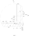
FIG 7 is a close-up view of a part B shown inFIG. 6 . - Reference numerals: 1, Vehicle; 10, Battery; 100, Battery cell; 110, Battery shell; 111, Accommodation cavity; 1111, Bearing bottom wall; 1112, Side wall; 1113, First opening; 112, Receding groove; 1121, First arc-shaped surface; 1122, Second arc-shaped surface; 1123, Third arc-shaped surface; 1124, Straight wall surface; 120, Electrode core; 121, Electrode assembly; 122, Electrical isolation part; 1221, Second opening; 1222, Bottom plate portion; 1223, Side wall portion; 1206, Notch; 1201, Bottom corner portion; 1202, First corner portion; 1203, Bottom surface; 1204, Side surface; 1205, Second corner portion; 130, Top cover; 131, Top cover body; 132, Protrusion portion; 20, Motor; and 30, Controller.
- In order to make the above purposes, characteristics and advantages of the present application more obvious and understandable, the following is a detailed explanation of the specific implementations of the present application with reference to the accompanying drawings. Many specific details are set out in the description below in order to fully understand the present application. However, the present application can be implemented in many other ways different from those described herein, and a person skilled in the art may make similar improvements without contravening the meaning of the present application, and therefore the present application is not limited to the specific embodiments disclosed below.
- Understandably, in the description of the present application, a direction or a positional relationship indicated by the terms such as "center", "longitudinal", "transverse", "length", "width", "thickness", "up", "down", "before", "after", "left", "right", "vertical", "horizontal", "top", "bottom", "in", "out", "clockwise", "counterclockwise", "axial", "radial", and "circumferential" is a direction or positional relationship based on the illustration in the drawings, and is merely intended for ease or brevity of description of the present application, but not intended to indicate or imply that the mentioned device or component must be located in the specified direction or constructed or operated in the specified direction. Therefore, such terms are not intended as a limitation on the present application.
- In addition, the terms "first" and "second" are used merely for descriptive purposes but are not to be construed as indicating or implying relative importance or implicitly specifying the quantity of technical features indicated. Therefore, a feature defined with "first" or "second" may explicitly or implicitly include at least one of the features. In the description of the present application, unless otherwise expressly and specifically defined, "a plurality of" means at least two, for example, two, three, etc.
- In the present application, unless otherwise expressly specified or defined, the terms such as "mount", "concatenate", "connect" and "fix" shall be understood broadly, for example, mean a fixed connection, a detachable connection, or a one-piece configuration; or mean a mechanical connection or an electrical connection; or mean a direct connection or an indirect connection implemented through an intermediary; or mean internal communication between two components or interaction between two components, unless otherwise expressly defined. A person of ordinary skill in the art may understand specific meaning of the above terms in the present application based on specific circumstances.
- In the present application, unless otherwise expressly specified and qualified, a first feature being "on" or "under" a second feature may be that the first feature is in direct contact with the second feature, or the first feature is in indirect contact with the second feature through an intermediary. In addition, a first feature being "on", "above", or "over" a second feature may mean that the first feature is directly above or obliquely above the second feature, or just mean that the first feature is at an altitude higher than the second feature. A first feature being "under", "below", or "beneath" a second feature may mean that the first feature is exactly under or obliquely under the second feature, or just mean that the first feature is at an altitude lower than the second feature.
- It is hereby noted that when one component is expressed as being "fixed to" or "disposed on" another component, it may be directly located on the another component, or there may be components disposed therebetween. When one component is expressed as being "connected" to another component, it may be directly connected to the another component, or there may be components disposed therebetween at the same time. The terms "vertical", "horizontal", "upper", "lower", "left", "right" and similar expressions used herein are merely for the purpose of illustration, but do not represent the unique implementation.
- A battery includes a battery shell, an electrode core and a top cover. When assembling the battery, the electrode core is usually placed in the battery shell, and then the top cover covers the battery shell. However, the traditional battery has great safety hazards.
- Bottom rounded corners are usually designed at corners of the battery shell of the traditional battery, resulting in the bottom rounded corner of the battery shell is easy to contact with the bottom corner of the battery cell, which will produce extrusion pressure on the electrode core, resulting in great safety hazards of the traditional battery.
- Therefore, the present application designs a battery shell. The battery shell is provided with receding grooves used for receding bottom corner portions of an electrode core, so as to prevent the bottom corner portions of the electrode core from being in contact with the battery shell, which can effectively improve the safety of a battery.
- A battery shell, a battery cell and/or a battery disclosed in embodiments of the present application may be used in, but is not limited to be used in, an electrical device such as a vehicle, watercraft, or aircraft. The electrical device may be, but is not limited to, a mobile phone, a tablet, a laptop computer, an electric toy, an electric tool, an electric power cart, an electric vehicle, a ship, a spacecraft, or the like. The electric toy may include stationary or mobile electric toys, such as a game console, an electric car toy, an electric ship toy, an electric airplane toy, and the like. The spacecraft may include an airplane, a rocket, a space shuttle, a spaceship, and the like. A power supply system consisting of the electrical device with the battery cells and/or batteries disclosed in the present application may be used so as to facilitate the supply of electric drive to the electrical device.
- Referring to
FIG. 1, FIG. 1 is a schematic structural diagram of avehicle 1 according to some embodiments of the present application. Thevehicle 1 may be an oil-fueled vehicle, a natural gas vehicle, or a new energy vehicle. The new energy vehicle may be a battery electric vehicle, a hybrid electric vehicle, a range-extended electric vehicle, or the like. Abattery 10 is disposed inside thevehicle 1. Thebattery 10 may be disposed at the bottom, front, or rear of thevehicle 1. Thebattery 10 may be used for supplying power to thevehicle 1. For example, thebattery 10 may serve as an operating power supply of thevehicle 1. Thevehicle 1 may further include amotor 20 and acontroller 30. Thecontroller 30 is used for controlling thebattery 10 to supply power to themotor 20, for example, to meet the operating power requirements of thevehicle 1 in start, navigation and running. - In some embodiments of the present application, the
battery 10 serves not only as an operating power supply of thevehicle 1, but may also serve as a driving power supply of thevehicle 1 to provide driving power for thevehicle 1 in place of or partly in place of fuel oil or natural gas. - The
battery 10 provided by an embodiment of the present application includes abattery cell 100. -
FIG. 2 is a schematic structural diagram of abattery cell 100 according to an embodiment of the present application.FIG. 3 is a schematic exploded diagram of thebattery cell 100 according to an embodiment of the present application.FIG. 4 is a sectional diagram of thebattery cell 100 according to an embodiment of the present application. - Referring to
FIG. 2 to FIG. 5 , thebattery cell 100 provided by an embodiment of the present application includes abattery shell 110. - Referring to
FIG. 3 , thebattery cell 100 further includes anelectrode core 120, and theelectrode core 120 can be accommodated in thebattery shell 110. - The
electrode core 120 includesbottom corner portions 1201, thebattery shell 110 has anaccommodation cavity 111 used for accommodating theelectrode core 120, theaccommodation cavity 111 includes a bearingbottom wall 1111, a plurality ofside walls 1112 and inner corner portions, and each inner corner portion is disposed between the bearingbottom wall 1111 and thecorresponding side walls 1112, to connect the bearingbottom wall 1111 and the twoadjacent side walls 1112, where the inner corner portions are provided with recedinggrooves 112 in a concave manner. - The bearing
bottom wall 1111 refers to a part of the groove wall of theaccommodation cavity 111 used for bearing theelectrode core 120, the bearingbottom wall 1111 is in contact with the bottom of theelectrode core 120, and the bearingbottom wall 1111 is used for bearing theelectrode core 120. - The receding
grooves 112 are formed at the inner corner portions between the bearingbottom wall 1111 and thecorresponding side walls 1112 and are concave, that is, the recedinggrooves 112 ae formed at the connections between the bearingbottom wall 1111 and thecorresponding side walls 1112 and are concave, so as to be used for receding thebottom corner portions 1201 of theelectrode core 120. Exemplarily, theaccommodation cavity 111 also includes afirst opening 1113 opposite and spaced apart from the bearingbottom wall 1111, and the recedinggrooves 112 are concave in a direction of thefirst opening 1113 towards the bearingbottom wall 1111 with respect to the bearingbottom wall 1111. - The
electrode core 120 can be placed in theaccommodation cavity 111 and placed on the bearingbottom wall 1111, thebottom corner portions 1201 of theelectrode core 120 placed on the bearingbottom wall 1111 are located on the upper side of the bearingbottom wall 1111, and the recedinggrooves 112 are formed in the inner corner portions between the bearingbottom wall 1111 and theside walls 1112 and disposed in a concave manner. It is understood that thebottom corner portions 1201 of theelectrode core 120 can extend into the recedinggrooves 112 and can be spaced apart from the groove walls of the recedinggrooves 112. In this way, thebottom corner portions 1201 of theelectrode core 120 can be well prevented from being in contact with the inner corner portions between the bearingbottom wall 1111 and theside walls 1112, that is, thebottom corner portions 1201 can not be in contact with thebattery shell 110, and it is avoided that corresponding extrusion pressure is generated on theelectrode core 120 due to the contact between thebattery shell 110 and thebottom corner portions 1201, so that the use of the recedinggrooves 112 can effectively improve the safety of thebattery 10. - In some embodiments, the bearing
bottom wall 1111 and theside walls 1112 are perpendicular to each other, and theside walls 1112 are parallel to an axis direction of theaccommodation cavity 111. - The inner corner portions are conveniently formed between the bearing
bottom wall 1111 and thecorresponding side walls 1112, so as to form the corresponding recedinggrooves 112. - Referring to
FIG. 5 andFIG. 7 , in some embodiments, along a direction perpendicular to the bearingbottom wall 1111, a first preset interval D1 is provided between the very bottom of the groove wall of each recedinggroove 112 and the bearingbottom wall 1111. - If the interval between the very bottom of the groove wall of each receding
groove 112 and the bearingbottom wall 1111 is too small, the processing of the recedinggroove 112 will be affected; and if the interval between the very bottom of the groove wall of each recedinggroove 112 and the bearingbottom wall 1111 is too large, the internal space of thebattery shell 110 will be affected, and thus the energy density of thebattery cell 100 is affected. - Therefore, it is necessary to provide a first preset interval D1 between the very bottom of the groove wall of each receding
groove 112 and the bearingbottom wall 1111. Therefore, it not only facilitates the processing of the recedinggrooves 112, but also ensures the internal space of thebattery shell 110, and thus ensures the energy density of thebattery cell 100. - In some embodiments, the first preset interval D1 is greater than or equal to 0.3 millimeter (mm).
- The first preset interval D1 is set to be greater than or equal to 0.3 millimeter (mm), which not only facilitates the processing of the receding
grooves 112, but also ensures the energy density of thebattery cell 100. - In some embodiments, the groove wall of each receding
groove 112 is in rounded corner connection with the bearingbottom wall 1111 and thecorresponding side wall 1112 respectively. - It is understood that the groove wall of each receding
groove 112 is in an arc transition to the bearingbottom wall 1111 and thecorresponding side wall 1112, and the stress concentration can be avoided at the connection between the recedinggrooves 112 and the bearingbottom wall 1111, and at the connection between the recedinggrooves 112 and thecorresponding side walls 1112, which is conducive to improving the strength of thebattery shell 110. - In some embodiments, referring to
FIG. 5 andFIG. 7 , the groove wall of each recedinggroove 112 includes a first arc-shapedsurface 1121 tangent to the bearingbottom wall 1111 and a second arc-shapedsurface 1122 tangent to thecorresponding side wall 1112. - The side that is of the first arc-shaped
surface 1121 and that is away from the bearingbottom wall 1111 may be directly connected with the side that is of the second arc-shapedsurface 1122 and that is away from thecorresponding side wall 1112, and the side that is of the first arc-shapedsurface 1121 and that is away from the bearingbottom wall 1111 may also be indirectly connected with the side that is of the second arc-shapedsurface 1122 and that is away from thecorresponding side wall 1112, which is not specifically limited herein. - The first arc-shaped
surfaces 1121 tangent to the bearingbottom wall 1111 and the second arc-shapedsurfaces 1122 tangent to thecorresponding side walls 1112 can well avoid the stress concentration at the connection between the recedinggrooves 112 and the bearingbottom wall 1111, and at the connection between the recedinggrooves 112 and thecorresponding side walls 1112, which is conducive to improving the strength of thebattery shell 110. - In some embodiments (not shown in figures), the first arc-shaped
surface 1121 and the second arc-shapedsurface 1122 are directly connected. - Therefore, it facilitates the processing of the receding
grooves 112 and is conducive to improving the processing efficiency of thebattery shell 110. - In some embodiments, referring to
FIG. 5 , each recedinggroove 112 further includes a third arc-shapedsurface 1123 connected between the first arc-shapedsurface 1121 and the second arc-shapedsurface 1122, and the third arc-shapedsurface 1123 is disposed tangent to the first arc-shapedsurface 1121 and the second arc-shapedsurface 1122 respectively. - It is understood that the side that is of the first arc-shaped
surface 1121 and that is away from the bearingbottom wall 1111 is indirectly connected with the side that is of the second arc-shapedsurface 1122 and that is away from thecorresponding side wall 1112. - Since the third arc-shaped
surface 1123 is disposed tangent to the first arc-shapedsurface 1121 and the second arc-shapedsurface 1122 respectively, the first arc-shapedsurface 1121 and the second arc-shapedsurface 1122 are in rounded corner transition, the stress concentration can be avoided at the connection between the recedinggrooves 112 and the bearingbottom wall 1111, and at the connection between the recedinggrooves 112 and thecorresponding side walls 1112, the stress concentration can also be avoided at the groove walls of the recedinggrooves 112, and the strength of thebattery shell 110 can be better improved. - In some embodiments, referring to
FIG. 7 , the groove wall of each recedinggroove 112 further includes astraight wall surface 1124, along the direction perpendicular to the bearingbottom wall 1111, thestraight wall surface 1124 is spaced apart from the bearingbottom wall 1111, and thestraight wall surface 1124 is tangent to the first arc-shapedsurface 1121 and the second arc-shapedsurface 1122 respectively. - The
straight wall surface 1124 is roughly planar, may be parallel with the bearingbottom wall 1111, and may also be disposed at an angle with the bearingbottom wall 1111. - The
straight wall surface 1124 is spaced apart from the bearingbottom wall 1111, and thestraight wall surface 1124 is tangent to the first arc-shapedsurface 1121 and the second arc-shapedsurface 1122 respectively. It is understood that the recedinggrooves 112 are concave in the direction of the bearingbottom wall 1111 towards thestraight wall surfaces 1124 with respect to the bearingbottom wall 1111. In this way, thebottom corner portions 1201 of theelectrode core 120 placed on the bearingbottom wall 1111 can be well spaced apart from the groove walls of the recedinggrooves 112, so that it is avoided that corresponding extrusion pressure is generated on theelectrode core 120 due to the contact between thebattery shell 110 and thebottom corner portions 1201, and the safety of thebattery 10 can be effectively improved. - In some embodiments, referring to
FIG. 7 , thestraight wall surface 1124 is parallel with the bearingbottom wall 1111. - Therefore, the
bottom corner portions 1201 of theelectrode core 120 placed on the bearingbottom wall 1111 can be well spaced apart from the groove walls of the recedinggrooves 112, and the safety of thebattery 10 can be better improved. - In some embodiments, referring to
FIG. 7 , the third arc-shapedsurface 1123 is disposed between thestraight wall surface 1124 and the first arc-shapedsurface 1121. - Therefore, the stress concentration can be avoided at the groove walls of the receding
grooves 112 and the strength of thebattery shell 110 can be well improved. - In some embodiments, referring to
FIG. 5 andFIG. 7 , along a direction perpendicular to eachside wall 1112, a second preset interval D2 is provided between the farthest point on an edge of the first arc-shapedsurface 1121 tangent to the bearingbottom wall 1111 and theside wall 1112. - The
side wall 1112 is thecorresponding side wall 1112 of the recedinggroove 112 where the first arc-shapedsurface 1121 is located. - If the interval between the farthest point on the edge of the first arc-shaped
surface 1121 tangent to the bearingbottom wall 1111 and theside wall 1112 along the direction perpendicular to eachside wall 1112 is too small, it is difficult to ensure the certain interval between the peripheral wall of theelectrode core 120 and theside walls 1112 and the energy density of thebattery cell 100 at the same time. If the interval between the farthest point on the edge of the first arc-shapedsurface 1121 tangent to the bearingbottom wall 1111 and theside wall 1112 along the direction perpendicular to eachside wall 1112 is too large, the area of the bearingbottom wall 1111 is affected, and thus the bearing pressure is too large. Therefore, it is necessary to provide a second preset interval D2 between the farthest point on the edge of the first arc-shapedsurface 1121 tangent to the bearingbottom wall 1111 and theside wall 1112 along the direction perpendicular to eachside wall 1112. It can not only ensure the energy density of thebattery cell 100, but also ensure that there is a certain interval between the peripheral wall of theelectrode core 120 and theside walls 1112, and avoid excessive bearing pressure. - In some embodiments, the second preset interval D2 is greater than or equal to 0.5 millimeter (mm).
- The second preset interval D2 is set to be greater than or equal to 0.5 millimeter (mm), which can not only ensure the energy density of the
battery cell 100, but also ensure that there is a certain interval between the peripheral wall of theelectrode core 120 and theside walls 1112, and avoid excessive bearing pressure. - In some embodiments, the
accommodation cavity 111 includes a bearingbottom wall 1111, a plurality ofside walls 1112 and inner corner portions, and each inner corner portion is disposed between the bearingbottom wall 1111 and thecorresponding side walls 1112, to connect the bearingbottom wall 1111 and the twoadjacent side walls 1112, where the inner corner portions are provided with recedinggrooves 112 in a concave manner. The groove wall of each recedinggroove 112 is in rounded corner connection with the bearingbottom wall 1111 and thecorresponding side wall 1112 respectively. - The use of the receding
grooves 112 can effectively improve the safety of thebattery 10, and can also avoid the stress concentration at the connection between the recedinggrooves 112 and the bearingbottom wall 1111, and at the connection between the recedinggrooves 112 and thecorresponding side walls 1112, which is conducive to improving the strength of thebattery shell 110. - A
battery cell 100 provided by an embodiment of the present application includes the foregoingbattery shell 110 and anelectrode core 120, where theelectrode core 120 hasbottom corner portions 1201, theelectrode core 120 is accommodated in theaccommodation cavity 111 and placed on the bearingbottom wall 1111, and thebottom corner portions 1201 are separated from the groove walls of the recedinggrooves 112. - It is avoided that the corresponding extrusion pressure is generated on the
electrode core 120 due to the contact between thebattery shell 110 and thebottom corner portions 1201. The safety of thebattery 10 can be effectively improved by using the recedinggrooves 112 of thebattery shell 110. - In some embodiments, the
electrode core 120 includes anelectrode assembly 121 and anelectrical isolation part 122, and theelectrode assembly 121 is electrically isolated from thebattery shell 110 through theelectrical isolation part 122. Thebottom corner portions 1201 includefirst corner portions 1202 disposed on theelectrode assembly 121 andsecond corner portions 1205 disposed on theelectrical isolation part 122. - The
electrical isolation part 122 refers to a part that can electrically isolate theelectrode assembly 121 from thebattery shell 110, and may be made of an insulating material. - The
electrical isolation part 122 may wrap the bottom and peripheral wall of theelectrode assembly 121 so as to electrically isolate theelectrode assembly 121 from thebattery shell 110. - The
electrical isolation part 122 can electrically isolate theelectrode assembly 121 from thebattery shell 110, which is conducive to improving the safety of thebattery cell 100. - In some embodiments, referring to
FIG. 5 andFIG. 7 , theelectrode assembly 121 has abottom surface 1203 and a plurality ofside surfaces 1204, where thefirst corner portions 1202 are connected between thebottom surface 1203 and the corresponding side surfaces 1204. - Each
first corner portion 1202 is connected between thebottom surface 1203 and the corresponding twoadjacent side surfaces 1204, located in the recedinggroove 112 and separated from the groove wall of the recedinggroove 112 to avoid the contact between thefirst corner portion 1202 and thebattery shell 110, which can improve the safety of thebattery cell 100. - In some embodiments, referring to
FIG. 3 , theelectrical isolation part 122 defines an electrical cavity having asecond opening 1221 at one end and used for receiving theelectrode assembly 121, theelectrode assembly 121 is disposed in the electrical cavity through thesecond opening 1221, and thesecond corner portions 1205 surround thefirst corner portions 1202. - The
second corner portions 1205 are located at the bottom corner parts of theelectrical isolation part 122 and not in contact with the bearingbottom wall 1111. - Referring to
FIG. 3 andFIG. 7 , theelectrical isolation part 122 is provided with anotch 1206 which communicates with the electrical cavity and theaccommodation cavity 111 respectively, and thenotch 1206 is adjacent to thesecond corner portion 1205, thus, an electrolyte solution in the electrical cavity can flow into theaccommodation cavity 111 through thenotch 1206, which can improve the volume of the electrolyte solution to a certain extent, and is conducive to improving the energy density of thebattery cell 100. - Referring to
FIG. 3 andFIG. 7 , theelectrical isolation part 122 includes abottom plate portion 1222 and aside wall portion 1223 connected to thebottom plate portion 1222, and thenotch 1206 is located between thebottom plate portion 1222 and theside wall portion 1223. - The
side wall portion 1223 and thebottom plate portion 1222 are integrally formed to improve the strength of theelectrical isolation part 122. Theside wall portion 1223 is bent relative to thebottom plate portion 1222, and theside wall portion 1223 surrounds the peripheral wall of theelectrode assembly 121, so that theelectrode assembly 121 is placed on the bearingbottom wall 1111 through thebottom plate portion 1222 of theelectrical isolation part 122, the bottom of theelectrode assembly 121 is electrically isolated from thebattery shell 110 through thebottom plate portion 1222, and the peripheral wall of theelectrode assembly 121 is electrically isolated from thebattery shell 110 through theside wall portion 1223. - In some embodiments, the
accommodation cavity 111 also includes afirst opening 1113 spaced apart from the bearingbottom wall 1111 along the axis direction of theaccommodation cavity 111, thebattery cell 100 also includes atop cover 130, and thetop cover 130 includes atop cover body 131 and at least one protrusion portion 132 (as shown inFIG. 3 ), where thetop cover body 131 is connected to one end of thebattery shell 110 to close thefirst opening 1113 of theaccommodation cavity 111. At least oneprotrusion portion 132 is arranged on the side of thetop cover body 131 towards theaccommodation cavity 111 and is connected to one end of theelectrical isolation part 122 provided with thesecond opening 1221. - One or
more protrusion portions 132 may be provided, which is not specifically limited herein. - Therefore, the
top cover body 131 of thetop cover 130 is connected to one end of thebattery shell 110 to close thefirst opening 1113 of theaccommodation cavity 111, and at least oneprotrusion portion 132 of thetop cover 130 is connected to one end of theelectrical isolation part 122 provided with thesecond opening 1221, which is conducive to improving the overall strength and stability of thebattery cell 100. - A
battery 10 provided by an embodiment of the present application includes the foregoingbattery cell 100. - An electrical device provided by an embodiment of the present application includes the foregoing
battery 10. - Various technical features of the foregoing embodiments may be combined arbitrarily, and all possible combinations of the various technical features of the foregoing embodiments have not been described for the sake of concise description; however, as long as there is no conflict in the combinations of these technical features, they shall all be regarded as falling within the scope of this specification.
- The foregoing embodiments merely describe several implementations of the present application. The description is relatively detailed, but constitutes no limitation on the patent scope of the present application. It is hereby noted that several variations and improvements, which may be made to the embodiments by a person of ordinary skill in the art without departing from the concept of the present application, fall within the protection scope of the present application. Therefore, the patent protection scope of the present application should be subject to the attached claims.
Claims (16)
- A battery shell, having an accommodation cavity (111), the accommodation cavity (111) comprising:a bearing bottom wall (1111);a plurality of side walls (1112); andinner corner portions, connected between the bearing bottom wall (1111) and the corresponding side walls (1112);wherein the inner corner portions are provided with receding grooves (112) in a concave manner.
- The battery shell according to claim 1, wherein along a direction perpendicular to the bearing bottom wall (1111), a first preset interval D1 is provided between the very bottom of a groove wall of each receding groove (112) and the bearing bottom wall (1111).
- The battery shell according to claim 2, wherein the first preset interval D1 is greater than or equal to 0.3 mm.
- The battery shell according to any one of claims 1 to 3, wherein the groove wall of each receding groove (112) is in rounded corner connection with the bearing bottom wall (1111) and the corresponding side wall (1112) respectively.
- The battery shell according to claim 4, wherein the groove wall of each receding groove (112) comprises a first arc-shaped surface (1121) tangent to the bearing bottom wall (1111) and a second arc-shaped surface (1122) tangent to the corresponding side wall (1112).
- The battery shell according to claim 5, wherein the first arc-shaped surface (1121) and the second arc-shaped surface (1122) are directly connected.
- The battery shell according to claim 5, wherein each receding groove (112) further comprises a third arc-shaped surface (1123) connected between the first arc-shaped surface (1121) and the second arc-shaped surface (1122); and
the third arc-shaped surface (1123) is disposed tangent to the first arc-shaped surface (1121) and the second arc-shaped surface (1122) respectively. - The battery shell according to claim 5, wherein the groove wall of each receding groove (112) further comprises a straight wall surface (1124), and along the direction perpendicular to the bearing bottom wall (1111), the straight wall surface (1124) is spaced apart from the bearing bottom wall (1111); and
the straight wall surface (1124) is tangent to the first arc-shaped surface (1121) and the second arc-shaped surface (1122) respectively. - The battery shell according to claim 8, wherein the straight wall surface (1124) is disposed parallel with the bearing bottom wall (1111).
- The battery shell according to claim 5, wherein along a direction perpendicular to each side wall (1112), a second preset interval D2 is provided between the farthest point on an edge of the first arc-shaped surface (1121) tangent to the bearing bottom wall (1111) and the side wall (1112).
- The battery shell according to claim 10, wherein the second preset interval D2 is greater than or equal to 0.5 mm.
- A battery cell, comprising:the battery shell (110) according to any one of claims 1 to 11; andan electrode core (120), having bottom corner portions (1201);wherein the electrode core (120) is accommodated in the accommodation cavity (111) and placed on the bearing bottom wall (1111); andthe bottom corner portions (1201) are separated from the groove walls of the receding grooves (112).
- The battery cell according to claim 12, wherein the electrode core (120) comprises:an electrode assembly (121); andan electrical isolation part (122), the electrode assembly (121) being electrically isolated from the battery shell (110) through the electrical isolation part (122); andthe bottom corner portions (1201) comprising first corner portions (1202) disposed on the electrode assembly (121) and second corner portions (1205) disposed on the electrical isolation part (122).
- The battery cell according to claim 13, wherein the electrode assembly (121) has:a bottom surface (1203); anda plurality of side surfaces (1204);wherein each first corner portion (1202) is connected between the bottom surface (1203) and the corresponding side surface (1204).
- A battery, comprising the battery cell (100) according to any one of claims 12 to 14.
- An electrical device, comprising the battery (10) according to claim 15.
Applications Claiming Priority (2)
| Application Number | Priority Date | Filing Date | Title |
|---|---|---|---|
| CN202222686468.3U CN218274855U (en) | 2022-10-12 | 2022-10-12 | Battery cases, battery cells, batteries and electrical devices |
| PCT/CN2023/123805 WO2024078500A1 (en) | 2022-10-12 | 2023-10-10 | Battery housing, battery cell, battery, and electrical apparatus |
Publications (2)
| Publication Number | Publication Date |
|---|---|
| EP4517978A1 true EP4517978A1 (en) | 2025-03-05 |
| EP4517978A4 EP4517978A4 (en) | 2025-08-06 |
Family
ID=84749602
Family Applications (1)
| Application Number | Title | Priority Date | Filing Date |
|---|---|---|---|
| EP23876702.4A Pending EP4517978A4 (en) | 2022-10-12 | 2023-10-10 | BATTERY CASING, BATTERY CELL, BATTERY AND ELECTRICAL DEVICE |
Country Status (4)
| Country | Link |
|---|---|
| US (1) | US20250070434A1 (en) |
| EP (1) | EP4517978A4 (en) |
| CN (1) | CN218274855U (en) |
| WO (1) | WO2024078500A1 (en) |
Cited By (1)
| Publication number | Priority date | Publication date | Assignee | Title |
|---|---|---|---|---|
| EP4546514A4 (en) * | 2022-11-07 | 2025-12-03 | Contemporary Amperex Technology Hong Kong Ltd | BATTERY CELL, BATTERY AND ELECTRICAL DEVICE |
Families Citing this family (6)
| Publication number | Priority date | Publication date | Assignee | Title |
|---|---|---|---|---|
| CN218274855U (en) * | 2022-10-12 | 2023-01-10 | 宁德时代新能源科技股份有限公司 | Battery cases, battery cells, batteries and electrical devices |
| CN220138471U (en) * | 2023-06-30 | 2023-12-05 | 蜂巢能源科技股份有限公司 | Battery case and battery |
| CN222914837U (en) * | 2024-06-14 | 2025-05-27 | 宁德时代新能源科技股份有限公司 | Battery cells, batteries and electrical devices |
| CN121149422A (en) * | 2024-06-14 | 2025-12-16 | 宁德时代新能源科技股份有限公司 | Battery cell casing manufacturing method, battery cell, battery and electrical device |
| CN223156147U (en) * | 2024-09-10 | 2025-07-25 | 广西宁福新能源科技有限公司 | A housing and a secondary battery |
| WO2026156533A1 (en) * | 2025-01-22 | 2026-07-30 | 宁德时代新能源科技股份有限公司 | Battery cell, related device, energy storage system and charging network |
Family Cites Families (7)
| Publication number | Priority date | Publication date | Assignee | Title |
|---|---|---|---|---|
| JP5779571B2 (en) * | 2012-11-30 | 2015-09-16 | 本田技研工業株式会社 | Battery storage structure for saddle riding type vehicle |
| JP6679260B2 (en) * | 2015-09-29 | 2020-04-15 | 三洋電機株式会社 | Battery pack |
| KR101950464B1 (en) * | 2015-11-30 | 2019-02-20 | 주식회사 엘지화학 | Battery Cell of Irregular Structure with Improved Sealing Reliability of Cell Case |
| CN209963093U (en) * | 2019-04-26 | 2020-01-17 | 宁德时代新能源科技股份有限公司 | Casing and secondary battery |
| CN214848728U (en) * | 2021-03-25 | 2021-11-23 | 湖北亿纬动力有限公司 | A single battery, battery module and vehicle |
| CN217134543U (en) * | 2022-06-14 | 2022-08-05 | 宁德时代新能源科技股份有限公司 | Battery cell, battery and power consumption device |
| CN218274855U (en) * | 2022-10-12 | 2023-01-10 | 宁德时代新能源科技股份有限公司 | Battery cases, battery cells, batteries and electrical devices |
-
2022
- 2022-10-12 CN CN202222686468.3U patent/CN218274855U/en active Active
-
2023
- 2023-10-10 WO PCT/CN2023/123805 patent/WO2024078500A1/en not_active Ceased
- 2023-10-10 EP EP23876702.4A patent/EP4517978A4/en active Pending
-
2024
- 2024-11-13 US US18/946,697 patent/US20250070434A1/en active Pending
Cited By (1)
| Publication number | Priority date | Publication date | Assignee | Title |
|---|---|---|---|---|
| EP4546514A4 (en) * | 2022-11-07 | 2025-12-03 | Contemporary Amperex Technology Hong Kong Ltd | BATTERY CELL, BATTERY AND ELECTRICAL DEVICE |
Also Published As
| Publication number | Publication date |
|---|---|
| US20250070434A1 (en) | 2025-02-27 |
| EP4517978A4 (en) | 2025-08-06 |
| CN218274855U (en) | 2023-01-10 |
| WO2024078500A1 (en) | 2024-04-18 |
Similar Documents
| Publication | Publication Date | Title |
|---|---|---|
| US20250070434A1 (en) | Battery shell, battery cell, battery and electrical device | |
| EP4425654A1 (en) | Battery cell, battery and electric device | |
| WO2024007447A1 (en) | End cap assembly, battery cell, battery and electric device | |
| CN219610664U (en) | Battery monomer, battery and power consumption device | |
| KR20220119369A (en) | Battery case, battery cell, battery, battery case manufacturing method and device | |
| CN217589304U (en) | Bottom supporting plate, battery monomer, battery pack and electric device | |
| WO2024082298A1 (en) | Battery module, battery, and electrical device | |
| CN219610581U (en) | Shell assembly, battery cell, battery and electric equipment | |
| US20250260133A1 (en) | Isolating plate assembly, battery module, battery pack, and electrical device | |
| US12469936B2 (en) | Battery cell, battery, and electric apparatus with tab including two different connecting portions | |
| US20220384918A1 (en) | Electrode assembly and related battery, device, manufacturing method, and manufacturing device | |
| US20240222752A1 (en) | Battery cell, battery, electrical apparatus, and manufacturing method of battery cell | |
| WO2025082046A1 (en) | Battery and electric device with same | |
| CN217903325U (en) | Battery shell, battery monomer, battery and power consumption device | |
| CN218498209U (en) | End cover assembly, battery monomer, battery and consumer | |
| WO2024026669A1 (en) | End cap assembly, battery cell, battery and electrical device | |
| KR20230048023A (en) | Adapter member, battery cell, battery, electric device and battery cell manufacturing method and manufacturing equipment | |
| CN221262547U (en) | Battery monomer, battery and electric equipment | |
| US20240006703A1 (en) | Battery, power consuming device and method for manufacturing battery | |
| EP4546516A1 (en) | Battery cell, battery, and electrical apparatus | |
| CN217281090U (en) | Fastener, battery and consumer | |
| EP4546514A1 (en) | Battery cell, battery, and electrical apparatus | |
| CN218867237U (en) | Shell, battery cell, battery and electrical equipment | |
| CN115360472B (en) | Battery pack and electric device | |
| CN224138277U (en) | Battery monomer, battery device and electric equipment |
Legal Events
| Date | Code | Title | Description |
|---|---|---|---|
| STAA | Information on the status of an ep patent application or granted ep patent |
Free format text: STATUS: THE INTERNATIONAL PUBLICATION HAS BEEN MADE |
|
| PUAI | Public reference made under article 153(3) epc to a published international application that has entered the european phase |
Free format text: ORIGINAL CODE: 0009012 |
|
| STAA | Information on the status of an ep patent application or granted ep patent |
Free format text: STATUS: REQUEST FOR EXAMINATION WAS MADE |
|
| 17P | Request for examination filed |
Effective date: 20241127 |
|
| AK | Designated contracting states |
Kind code of ref document: A1 Designated state(s): AL AT BE BG CH CY CZ DE DK EE ES FI FR GB GR HR HU IE IS IT LI LT LU LV MC ME MK MT NL NO PL PT RO RS SE SI SK SM TR |
|
| RAP1 | Party data changed (applicant data changed or rights of an application transferred) |
Owner name: CONTEMPORARY AMPEREX TECHNOLOGY(HONG KONG) LIMITED |
|
| REG | Reference to a national code |
Ref country code: DE Ref legal event code: R079 Free format text: PREVIOUS MAIN CLASS: H01M0050244000 Ipc: H01M0050103000 |
|
| A4 | Supplementary search report drawn up and despatched |
Effective date: 20250708 |
|
| RIC1 | Information provided on ipc code assigned before grant |
Ipc: H01M 50/103 20210101AFI20250702BHEP Ipc: H01M 50/586 20210101ALI20250702BHEP Ipc: H01M 50/593 20210101ALI20250702BHEP Ipc: H01M 50/209 20210101ALI20250702BHEP |
|
| DAV | Request for validation of the european patent (deleted) | ||
| DAX | Request for extension of the european patent (deleted) |