EP4517974A1 - Box body of battery, battery, and electric apparatus - Google Patents
Box body of battery, battery, and electric apparatus Download PDFInfo
- Publication number
- EP4517974A1 EP4517974A1 EP22952518.3A EP22952518A EP4517974A1 EP 4517974 A1 EP4517974 A1 EP 4517974A1 EP 22952518 A EP22952518 A EP 22952518A EP 4517974 A1 EP4517974 A1 EP 4517974A1
- Authority
- EP
- European Patent Office
- Prior art keywords
- battery
- protrusion
- case
- plate body
- side beams
- Prior art date
- Legal status (The legal status is an assumption and is not a legal conclusion. Google has not performed a legal analysis and makes no representation as to the accuracy of the status listed.)
- Pending
Links
Images

Classifications
-
- H—ELECTRICITY
- H01—ELECTRIC ELEMENTS
- H01M—PROCESSES OR MEANS, e.g. BATTERIES, FOR THE DIRECT CONVERSION OF CHEMICAL ENERGY INTO ELECTRICAL ENERGY
- H01M10/00—Secondary cells; Manufacture thereof
- H01M10/60—Heating or cooling; Temperature control
- H01M10/61—Types of temperature control
- H01M10/613—Cooling or keeping cold
-
- H—ELECTRICITY
- H01—ELECTRIC ELEMENTS
- H01M—PROCESSES OR MEANS, e.g. BATTERIES, FOR THE DIRECT CONVERSION OF CHEMICAL ENERGY INTO ELECTRICAL ENERGY
- H01M10/00—Secondary cells; Manufacture thereof
- H01M10/60—Heating or cooling; Temperature control
- H01M10/64—Heating or cooling; Temperature control characterised by the shape of the cells
- H01M10/647—Prismatic or flat cells, e.g. pouch cells
-
- H—ELECTRICITY
- H01—ELECTRIC ELEMENTS
- H01M—PROCESSES OR MEANS, e.g. BATTERIES, FOR THE DIRECT CONVERSION OF CHEMICAL ENERGY INTO ELECTRICAL ENERGY
- H01M10/00—Secondary cells; Manufacture thereof
- H01M10/60—Heating or cooling; Temperature control
- H01M10/65—Means for temperature control structurally associated with the cells
- H01M10/653—Means for temperature control structurally associated with the cells characterised by electrically insulating or thermally conductive materials
-
- H—ELECTRICITY
- H01—ELECTRIC ELEMENTS
- H01M—PROCESSES OR MEANS, e.g. BATTERIES, FOR THE DIRECT CONVERSION OF CHEMICAL ENERGY INTO ELECTRICAL ENERGY
- H01M10/00—Secondary cells; Manufacture thereof
- H01M10/60—Heating or cooling; Temperature control
- H01M10/65—Means for temperature control structurally associated with the cells
- H01M10/655—Solid structures for heat exchange or heat conduction
- H01M10/6556—Solid parts with flow channel passages or pipes for heat exchange
-
- H—ELECTRICITY
- H01—ELECTRIC ELEMENTS
- H01M—PROCESSES OR MEANS, e.g. BATTERIES, FOR THE DIRECT CONVERSION OF CHEMICAL ENERGY INTO ELECTRICAL ENERGY
- H01M50/00—Constructional details or processes of manufacture of the non-active parts of electrochemical cells other than fuel cells, e.g. hybrid cells
- H01M50/20—Mountings; Secondary casings or frames; Racks, modules or packs; Suspension devices; Shock absorbers; Transport or carrying devices; Holders
- H01M50/204—Racks, modules or packs for multiple batteries or multiple cells
- H01M50/207—Racks, modules or packs for multiple batteries or multiple cells characterised by their shape
- H01M50/209—Racks, modules or packs for multiple batteries or multiple cells characterised by their shape adapted for prismatic or rectangular cells
-
- H—ELECTRICITY
- H01—ELECTRIC ELEMENTS
- H01M—PROCESSES OR MEANS, e.g. BATTERIES, FOR THE DIRECT CONVERSION OF CHEMICAL ENERGY INTO ELECTRICAL ENERGY
- H01M50/00—Constructional details or processes of manufacture of the non-active parts of electrochemical cells other than fuel cells, e.g. hybrid cells
- H01M50/20—Mountings; Secondary casings or frames; Racks, modules or packs; Suspension devices; Shock absorbers; Transport or carrying devices; Holders
- H01M50/218—Mountings; Secondary casings or frames; Racks, modules or packs; Suspension devices; Shock absorbers; Transport or carrying devices; Holders characterised by the material
- H01M50/22—Mountings; Secondary casings or frames; Racks, modules or packs; Suspension devices; Shock absorbers; Transport or carrying devices; Holders characterised by the material of the casings or racks
- H01M50/222—Inorganic material
- H01M50/224—Metals
-
- H—ELECTRICITY
- H01—ELECTRIC ELEMENTS
- H01M—PROCESSES OR MEANS, e.g. BATTERIES, FOR THE DIRECT CONVERSION OF CHEMICAL ENERGY INTO ELECTRICAL ENERGY
- H01M50/00—Constructional details or processes of manufacture of the non-active parts of electrochemical cells other than fuel cells, e.g. hybrid cells
- H01M50/20—Mountings; Secondary casings or frames; Racks, modules or packs; Suspension devices; Shock absorbers; Transport or carrying devices; Holders
- H01M50/233—Mountings; Secondary casings or frames; Racks, modules or packs; Suspension devices; Shock absorbers; Transport or carrying devices; Holders characterised by physical properties of casings or racks, e.g. dimensions
-
- H—ELECTRICITY
- H01—ELECTRIC ELEMENTS
- H01M—PROCESSES OR MEANS, e.g. BATTERIES, FOR THE DIRECT CONVERSION OF CHEMICAL ENERGY INTO ELECTRICAL ENERGY
- H01M50/00—Constructional details or processes of manufacture of the non-active parts of electrochemical cells other than fuel cells, e.g. hybrid cells
- H01M50/20—Mountings; Secondary casings or frames; Racks, modules or packs; Suspension devices; Shock absorbers; Transport or carrying devices; Holders
- H01M50/233—Mountings; Secondary casings or frames; Racks, modules or packs; Suspension devices; Shock absorbers; Transport or carrying devices; Holders characterised by physical properties of casings or racks, e.g. dimensions
- H01M50/242—Mountings; Secondary casings or frames; Racks, modules or packs; Suspension devices; Shock absorbers; Transport or carrying devices; Holders characterised by physical properties of casings or racks, e.g. dimensions adapted for protecting batteries against vibrations, collision impact or swelling
-
- H—ELECTRICITY
- H01—ELECTRIC ELEMENTS
- H01M—PROCESSES OR MEANS, e.g. BATTERIES, FOR THE DIRECT CONVERSION OF CHEMICAL ENERGY INTO ELECTRICAL ENERGY
- H01M50/00—Constructional details or processes of manufacture of the non-active parts of electrochemical cells other than fuel cells, e.g. hybrid cells
- H01M50/20—Mountings; Secondary casings or frames; Racks, modules or packs; Suspension devices; Shock absorbers; Transport or carrying devices; Holders
- H01M50/244—Secondary casings; Racks; Suspension devices; Carrying devices; Holders characterised by their mounting method
-
- H—ELECTRICITY
- H01—ELECTRIC ELEMENTS
- H01M—PROCESSES OR MEANS, e.g. BATTERIES, FOR THE DIRECT CONVERSION OF CHEMICAL ENERGY INTO ELECTRICAL ENERGY
- H01M50/00—Constructional details or processes of manufacture of the non-active parts of electrochemical cells other than fuel cells, e.g. hybrid cells
- H01M50/20—Mountings; Secondary casings or frames; Racks, modules or packs; Suspension devices; Shock absorbers; Transport or carrying devices; Holders
- H01M50/249—Mountings; Secondary casings or frames; Racks, modules or packs; Suspension devices; Shock absorbers; Transport or carrying devices; Holders specially adapted for aircraft or vehicles, e.g. cars or trains
-
- H—ELECTRICITY
- H01—ELECTRIC ELEMENTS
- H01M—PROCESSES OR MEANS, e.g. BATTERIES, FOR THE DIRECT CONVERSION OF CHEMICAL ENERGY INTO ELECTRICAL ENERGY
- H01M50/00—Constructional details or processes of manufacture of the non-active parts of electrochemical cells other than fuel cells, e.g. hybrid cells
- H01M50/20—Mountings; Secondary casings or frames; Racks, modules or packs; Suspension devices; Shock absorbers; Transport or carrying devices; Holders
- H01M50/258—Modular batteries; Casings provided with means for assembling
-
- H—ELECTRICITY
- H01—ELECTRIC ELEMENTS
- H01M—PROCESSES OR MEANS, e.g. BATTERIES, FOR THE DIRECT CONVERSION OF CHEMICAL ENERGY INTO ELECTRICAL ENERGY
- H01M50/00—Constructional details or processes of manufacture of the non-active parts of electrochemical cells other than fuel cells, e.g. hybrid cells
- H01M50/20—Mountings; Secondary casings or frames; Racks, modules or packs; Suspension devices; Shock absorbers; Transport or carrying devices; Holders
- H01M50/262—Mountings; Secondary casings or frames; Racks, modules or packs; Suspension devices; Shock absorbers; Transport or carrying devices; Holders with fastening means, e.g. locks
- H01M50/264—Mountings; Secondary casings or frames; Racks, modules or packs; Suspension devices; Shock absorbers; Transport or carrying devices; Holders with fastening means, e.g. locks for cells or batteries, e.g. straps, tie rods or peripheral frames
-
- H—ELECTRICITY
- H01—ELECTRIC ELEMENTS
- H01M—PROCESSES OR MEANS, e.g. BATTERIES, FOR THE DIRECT CONVERSION OF CHEMICAL ENERGY INTO ELECTRICAL ENERGY
- H01M2220/00—Batteries for particular applications
- H01M2220/20—Batteries in motive systems, e.g. vehicle, ship, plane
-
- Y—GENERAL TAGGING OF NEW TECHNOLOGICAL DEVELOPMENTS; GENERAL TAGGING OF CROSS-SECTIONAL TECHNOLOGIES SPANNING OVER SEVERAL SECTIONS OF THE IPC; TECHNICAL SUBJECTS COVERED BY FORMER USPC CROSS-REFERENCE ART COLLECTIONS [XRACs] AND DIGESTS
- Y02—TECHNOLOGIES OR APPLICATIONS FOR MITIGATION OR ADAPTATION AGAINST CLIMATE CHANGE
- Y02E—REDUCTION OF GREENHOUSE GAS [GHG] EMISSIONS, RELATED TO ENERGY GENERATION, TRANSMISSION OR DISTRIBUTION
- Y02E60/00—Enabling technologies; Technologies with a potential or indirect contribution to GHG emissions mitigation
- Y02E60/10—Energy storage using batteries
Definitions
- the application relates to the field of battery, and in particular to a case of battery, a battery and an electric device.
- Battery cells are widely used in electronic equipments such as mobile phones, laptop computers, electric bicycles, electric automobiles, electric aircrafts, electric ships, electric toy cars, electric toy ships, electric toy planes, and electric tools etc.
- the plurality of side beams include two first side beams arranged opposite in a first direction and two second side beams arranged opposite in a second direction, the two first side beams and the two second side beams are arranged alternately and connected end to end, at least one of the second side beams includes the beam body and the protrusion, and the first direction intersects with the second direction.
- each of the two second side beams includes the beam body and the protrusion.
- the maximum size of the protrusion in the second direction is limited to be greater than or equal to 2mm, so as to meet the rigidity requirement of the case, reduce the amplitude of the case in shaking, and enhance safety of use of the battery.
- the size of the protrusion in the second direction is limited to be less than or equal to 100mm, and the size of the protrusion is controlled so as to reduce waste of the internal space of the battery, reduce the weight of the battery, and enhance the energy density of the battery.
- the maximum size of the protrusion in the second direction is limited to be greater than or equal to 10mm and less than or equal to 30mm.
- the maximum size of the protrusion in the second direction is H
- the weight of the battery is M
- H and M satisfy: 0.002mm/kg ⁇ H/M ⁇ 2mm/kg.
- the value of H/M is limited to be greater than or equal to 0.002mm/kg, so as to meet the rigidity requirement of the battery, reduce the amplitude of the case in shaking, and enhance safety of use of the battery.
- the value of H/M is limited to be less than or equal to 2mm/kg, so as to avoid the protrusion occupying too much space and having a too large mass, reduce the waste of the internal space of the battery, increase the space utilization rate, and enhance the energy density of the battery.
- H and M satisfy: 0.01 mm/kg ⁇ H/M ⁇ 0.3mm/kg.
- the protrusion includes a first plate body, a second plate body and a third plate body, the first plate body and the beam body are arranged spaced apart, the second plate body connects an end of the first plate body away from the base plate and the beam body, and the third plate body connects an end of the first plate body close to the base plate and the beam body.
- the protrusion is configured to include the first plate body, the second plate body and the third plate body, that is, the protrusion is of a hollow structure, which is easy to manufacture and does not excessively increase the weight of the case and enhances the energy density of the battery.
- an avoidance space for keeping off a component in the battery is formed alongside the second plate body away from the third plate body.
- an avoidance space is formed alongside the second plate body away from the third plate body to keep off a component in the battery, so as to avoid the failure of assembly resulting from an interference with a component in the battery.
- the second plate body is obliquely arranged at the beam body and extends from an end of the first plate body laterally away from the third plate body.
- the first plate body, the second plate body, the beam body and the third plate body are enclosed to form an accommodation cavity, and the protrusion further includes a reinforcement rib arranged in the accommodation cavity.
- the rigidity of the protrusion may be further enhanced, that is, the rigidity and the weight of the case are enhanced, and the amplitude of shaking is reduced.
- the embodiments of the application further provide a battery including the case of battery described above and a battery cell, and the battery cell is accommodated in an accommodation space.
- the battery further includes a heat management component, an avoidance space is formed alongside the protrusion away from the base plate, and the heat management component is at least partially arranged in the avoidance space.
- the avoidance space is formed alongside the protrusion away from the base plate, the protrusion and the heat management component are arranged spaced apart in an arrangement direction of the base plate and the protrusion, the protrusion forms a keep-off effect for the heat management component, and the protrusion is arranged by utilizing the space above the heat management component, so that the space utilization rate inside the case is increased, and the energy density per unit volume of the battery is enhanced.
- the battery cell is arranged spaced apart from the protrusion, and the minimum spacing between the two is 0.5mm-20mm.
- the minimum spacing between the battery cell and the protrusion is configured to be greater than or equal to 0.5mm, so that the local stress effect may be alleviated or even avoided, and the diving problem of the battery may be improved.
- the minimum spacing between the battery cell and the protrusion is configured to be less than or equal to 20mm, so that the waste of the internal space of the battery is reduced, and the energy density of the battery is enhanced.
- a gap between the battery cell and the protrusion is filled with a binder for binding the battery cell and the protrusion.
- the gap between the battery cell and the protrusion is filled with a binder, so that the protrusion and the battery cell are connected as a whole, the amplitude of the case in shaking may be significantly reduced, and the safety of use of the battery is enhanced.
- the embodiments of the application further provide an electric device including a battery described above used to provide electrical energy.
- the terms "mount”, “link”, “connect”, “attach” shall be interpreted expansively, for example, it may be fixed connection, removable connection or integral connection; may be direct connection or indirect connection via an intermediate medium, or may be communication inside two elements.
- the specific meaning of the above terms in the application can be interpreted depending on the specific situation.
- the same reference numerals denote the same components, and in the different embodiments, detailed description of the same components is omitted for brevity. It should be understood that the thickness, length, width, and the like of the various components, and the overall thickness, length, width, and the like of the integrated device in the embodiments of the application shown in the drawings are merely illustrative and should not be construed as limiting of the application.
- the battery cell may include a lithium ion secondary battery cell, a lithium ion primary battery cell, a lithium sulfur battery cell, a sodium lithium ion battery cell, a sodium ion battery cell, a magnesium ion battery cell, or the like, which is not limited by the embodiments of the application.
- the battery cell may be in the form of a cylinder, a flat body, a cuboid, or other shape, which is not limited by the embodiments of the application.
- the battery mentioned in the embodiments of the application refers to a single physical module including one or more battery cells to provide higher voltage and capacity.
- the battery mentioned in the application may include a battery module or a battery pack or the like.
- the battery generally includes a case for packaging one or more battery cells. The case can prevent liquid or other foreign matter from affecting the charging or discharging of the battery cell.
- the battery cell includes an electrode assembly and electrolyte solution, and the electrode includes a positive electrode sheet, a negative electrode sheet, and a separator.
- the battery cell operates mainly by moving metal ions between the positive and negative electrode sheets.
- the positive electrode sheet includes a positive electrode current collector and a positive electrode active material layer coated on a surface of the positive electrode current collector.
- the positive electrode current collector includes a positive electrode coating area and a positive electrode tab connected to the positive electrode coating area. The positive electrode coating area is coated with the positive electrode active material layer, and the positive electrode tab is not coated with the positive electrode active material layer.
- the material of the positive electrode current collector may be aluminum, the positive electrode active material layer includes a positive electrode active material, and the positive electrode active material may be lithium cobaltate, lithium iron phosphate, lithium ternary or lithium manganate, or the like.
- the negative electrode sheet includes a negative electrode current collector and a negative electrode active material layer coated on a surface of the negative electrode current collector.
- the negative electrode current collector includes a negative electrode coating area and a negative electrode tab connected to the negative electrode coating area. The negative electrode coating area is coated with the negative electrode active material layer, and the negative electrode tab is not coated with the negative electrode active material layer.
- the material of the negative electrode current collector may be copper, the negative electrode active material layer includes a negative electrode active material, and the negative electrode active material may be carbon, silicon, or the like.
- the material of the separator may be PP (polypropylene) or PE (polyethylene) or the like.
- the battery cell further includes a housing, and an accommodation cavity for accommodating the electrode assembly is formed inside the housing.
- the housing may protect the electrode assembly from the outside to prevent external foreign matter from affecting charging or discharging of the electrode assembly.
Landscapes
- Chemical & Material Sciences (AREA)
- Chemical Kinetics & Catalysis (AREA)
- Electrochemistry (AREA)
- General Chemical & Material Sciences (AREA)
- Engineering & Computer Science (AREA)
- Manufacturing & Machinery (AREA)
- Inorganic Chemistry (AREA)
- Aviation & Aerospace Engineering (AREA)
- Battery Mounting, Suspending (AREA)
Abstract
Description
- The application relates to the field of battery, and in particular to a case of battery, a battery and an electric device.
- Battery cells are widely used in electronic equipments such as mobile phones, laptop computers, electric bicycles, electric automobiles, electric aircrafts, electric ships, electric toy cars, electric toy ships, electric toy planes, and electric tools etc.
- In development of the battery technology, how to enhance safety of use of the battery cells is a development direction in the battery technology.
- The application provides a case of battery, a battery and an electric device, which can enhance safety of use of the battery cells.
- In a first aspect, the embodiments of the application provide a case of battery including a base plate and a plurality of side beams. The plurality of side beams are connected to the base plate and enclosed together with the base plate to form an accommodation space, wherein at least one of the side beams includes a beam body and a protrusion protruding from a surface of the beam body facing towards the accommodation space.
- In the technical solution described above, the protrusion facing towards the accommodation space is provided to increases rigidity of the side beams of the case, reduce amplitude of the case in shaking, and thereby reduce and even eliminate a relative displacement between the case and the battery cell to enhance safety of use of the battery.
- In some embodiments, the plurality of side beams include two first side beams arranged opposite in a first direction and two second side beams arranged opposite in a second direction, the two first side beams and the two second side beams are arranged alternately and connected end to end, at least one of the second side beams includes the beam body and the protrusion, and the first direction intersects with the second direction.
- In the technical solution described above, the two first side beams and the two second side beams are enclosed to form a quadrangular accommodation space in order to facilitate processing and manufacturing.
- In some embodiments, each of the two second side beams includes the beam body and the protrusion.
- In the technical solution described above, each of the two side beams includes the protrusion, so that not only the rigidity of the case is significantly increased and the amplitude of the case is reduced, but also the battery cell may limit the position of the case in the second direction through the two protrusions to further reduce the amplitude of the case in vibration and enhance safety of use of the battery.
- In some embodiments, a spacing between the two first side beams is greater than or equal to a spacing between the two second side beams.
- In the technical solution described above, the spacing between the two first side beams is greater than or equal to the spacing between the two second side beams, and correspondingly, the size of the battery cell in the first direction is greater than the size in the second direction. Therefore, in the case that the second side beam includes the protrusion, the size of the protrusion may be greater than that in the case that the first side beam includes the protrusion, so that the rigidity of the case may be stronger.
- In some embodiments, the maximum size of the protrusion in the second direction is 2mm-100mm.
- In the technical solution described above, the maximum size of the protrusion in the second direction is limited to be greater than or equal to 2mm, so as to meet the rigidity requirement of the case, reduce the amplitude of the case in shaking, and enhance safety of use of the battery. The size of the protrusion in the second direction is limited to be less than or equal to 100mm, and the size of the protrusion is controlled so as to reduce waste of the internal space of the battery, reduce the weight of the battery, and enhance the energy density of the battery.
- In some embodiments, the maximum size of the protrusion in the second direction is 10mm-30mm.
- In the technical solution described above, the maximum size of the protrusion in the second direction is limited to be greater than or equal to 10mm and less than or equal to 30mm. After a plurality of tests and analyses, the inventor concludes that, by limiting the maximum size of the protrusion in the second direction to this range, the safety of use of the battery and the energy density of the battery may be balanced better, that is, the safety of use of the battery is higher and the energy density of the battery is larger.
- In some embodiments, the maximum size of the protrusion in the second direction is H, the weight of the battery is M, and H and M satisfy: 0.002mm/kg≤H/M≤2mm/kg.
- In the technical solution described above, the value of H/M is limited to be greater than or equal to 0.002mm/kg, so as to meet the rigidity requirement of the battery, reduce the amplitude of the case in shaking, and enhance safety of use of the battery. The value of H/M is limited to be less than or equal to 2mm/kg, so as to avoid the protrusion occupying too much space and having a too large mass, reduce the waste of the internal space of the battery, increase the space utilization rate, and enhance the energy density of the battery.
- In some embodiments, H and M satisfy: 0.01 mm/kg≤H/M≤0.3mm/kg.
- In the technical solution described above, by limiting the value of H/M to this range, the safety of use and the energy density of the battery may be balanced better, that is, the safety of use of the battery is higher and the energy density is larger.
- In some embodiments, the protrusion includes a first plate body, a second plate body and a third plate body, the first plate body and the beam body are arranged spaced apart, the second plate body connects an end of the first plate body away from the base plate and the beam body, and the third plate body connects an end of the first plate body close to the base plate and the beam body.
- In the technical solution described above, the protrusion is configured to include the first plate body, the second plate body and the third plate body, that is, the protrusion is of a hollow structure, which is easy to manufacture and does not excessively increase the weight of the case and enhances the energy density of the battery.
- In some embodiments, an avoidance space for keeping off a component in the battery is formed alongside the second plate body away from the third plate body.
- In the technical solution described above, an avoidance space is formed alongside the second plate body away from the third plate body to keep off a component in the battery, so as to avoid the failure of assembly resulting from an interference with a component in the battery.
- In some embodiments, the second plate body is obliquely arranged at the beam body and extends from an end of the first plate body laterally away from the third plate body.
- In the technical solution described above, the second plate body is obliquely arranged at the beam body and extends from the end of the first plate body laterally away from the third plate body, so that the enclosed volume of the protrusion and the beam body may be increased to thereby further increase the rigidity of the protrusion and reduce the amplitude of shaking.
- In some embodiments, the first plate body extends in a thickness direction of the base plate and abuts with the base plate, and the third plate body is connected to the base plate.
- In the technical solution described above, the protrusion and the base plate are connected together, so that the overall rigidity of the case is further enhanced, and the amplitude of shaking is reduced.
- In some embodiments, the first plate body, the second plate body, the beam body and the third plate body are enclosed to form an accommodation cavity, and the protrusion further includes a reinforcement rib arranged in the accommodation cavity.
- In the technical solution described above, by providing the reinforcement rib in the accommodation cavity, the rigidity of the protrusion may be further enhanced, that is, the rigidity and the weight of the case are enhanced, and the amplitude of shaking is reduced.
- In a second aspect, the embodiments of the application further provide a battery including the case of battery described above and a battery cell, and the battery cell is accommodated in an accommodation space.
- In some embodiments, the battery further includes a heat management component, an avoidance space is formed alongside the protrusion away from the base plate, and the heat management component is at least partially arranged in the avoidance space.
- In the technical solution described above, the avoidance space is formed alongside the protrusion away from the base plate, the protrusion and the heat management component are arranged spaced apart in an arrangement direction of the base plate and the protrusion, the protrusion forms a keep-off effect for the heat management component, and the protrusion is arranged by utilizing the space above the heat management component, so that the space utilization rate inside the case is increased, and the energy density per unit volume of the battery is enhanced.
- In some embodiments, the battery cell is arranged spaced apart from the protrusion, and the minimum spacing between the two is 0.5mm-20mm.
- In the technical solution described above, the minimum spacing between the battery cell and the protrusion is configured to be greater than or equal to 0.5mm, so that the local stress effect may be alleviated or even avoided, and the diving problem of the battery may be improved. The minimum spacing between the battery cell and the protrusion is configured to be less than or equal to 20mm, so that the waste of the internal space of the battery is reduced, and the energy density of the battery is enhanced.
- In some embodiments, a gap between the battery cell and the protrusion is filled with a binder for binding the battery cell and the protrusion.
- In the technical solution described above, the gap between the battery cell and the protrusion is filled with a binder, so that the protrusion and the battery cell are connected as a whole, the amplitude of the case in shaking may be significantly reduced, and the safety of use of the battery is enhanced.
- In a third aspect, the embodiments of the application further provide an electric device including a battery described above used to provide electrical energy.
- In order to illustrate the technical solutions in embodiments of the application more clearly, the drawings to be used in the embodiments of the application will be briefly described below. Obviously, the drawings described below are merely some embodiments of the application, and it is also possible for a person of ordinary skill in the art to obtain further drawings from these drawings without creative work.
-
Fig. 1 is a schematic structural view of a vehicle provided by some embodiments of the application; -
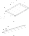
Fig. 2 is a schematic explosive structural view of a battery provided by some embodiments of the application; -
Fig. 3 is a schematic partial structural view of a case of the battery as shown inFig. 2 ; -
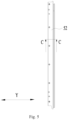
Fig. 4 is a schematic structural view of a side beam in the case of the battery provided by some embodiments of the application; -
Fig. 5 is a top view of the side beam as shown inFig. 4 ; -
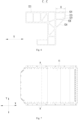
Fig. 6 is a sectional view of the side beam at C-C as shown inFig. 5 . -
Fig. 7 is a top view of the battery provided by some embodiments of the application; -
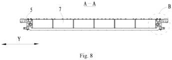
Fig. 8 is a sectional view of the battery at A-A as shown inFig. 7 ; -
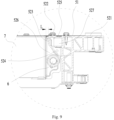
Fig. 9 is an enlarged view at B inFig. 8 ; - The views are not necessarily plotted in actual proportion in the drawings.
- The reference numbers in the detailed embodiments are as follows:
- 1 vehicle; 2 battery; 3 controller; 4 motor;
- 5 case; 51 base plate; 52 side beam; 521 beam body; 522 protrusion; 523 first plate body; 524 second plate body; 525 third plate body; 526 avoidance space; 527
accommodation cavity 528 reinforcement rib; 53 first side beam; 54 second side beam; 55 accommodation space; 56 cover plate; - 6 heat management component; 7 battery cell;
- X first direction; Y second direction.
- In order to make the purpose, the solution and the advantages of the embodiments of the application clearer, the technical solution of the embodiments of the application will be described clearly below with reference to the accompanying drawings. It is obvious that the embodiments as described are only a part of the embodiments of the application, rather than all of the embodiments. Based on the embodiments of the application, all other embodiments obtained by a person of ordinary skill in the art without creative efforts shall fall within the protection scope of the application.
- Unless otherwise defined, all the technical and scientific terms used in the application have the same meanings as commonly understood by a person skilled in the art of the application. The terms used in the description of this application is for the purpose of describing specific embodiments only and is not intended to limit the application. The terms "comprise", "have" and any variations thereof in the description and claims of the application and the brief description of the drawings above are intended to cover non-exclusive inclusions. The terms "first", "second" and the like in the description and claims of the application or in the aforesaid drawings are used to distinguish different objects and are not used to describe a particular order or primary-secondary relationship.
- Reference to "embodiment" in the application means that the specific features, structures, or characteristics described in connection with the embodiment may be included in at least one embodiment of the application. The presence of this phrase at various locations in the description does not necessarily refer to the same embodiment, nor is it a separate or alternative embodiment that is mutually exclusive from other embodiments.
- In the description of the application, it is noted that, except as otherwise stipulated or limited explicitly, the terms "mount", "link", "connect", "attach" shall be interpreted expansively, for example, it may be fixed connection, removable connection or integral connection; may be direct connection or indirect connection via an intermediate medium, or may be communication inside two elements. For a person of ordinary skill in the art, the specific meaning of the above terms in the application can be interpreted depending on the specific situation.
- In the application, the term "and/or" is merely to describe an association relationship of associated objects, meaning that there may be three relationship, for example, A and/or B may mean three cases that A exists alone, A and B exist simultaneously, and B exists alone. In addition, the character "/" in the application generally indicates that the related objects before and after have an "or" relationship.
- In the embodiments of the application, the same reference numerals denote the same components, and in the different embodiments, detailed description of the same components is omitted for brevity. It should be understood that the thickness, length, width, and the like of the various components, and the overall thickness, length, width, and the like of the integrated device in the embodiments of the application shown in the drawings are merely illustrative and should not be construed as limiting of the application.
- Reference to "a plurality of" in the application means two or more (including two).
- In the application, the battery cell may include a lithium ion secondary battery cell, a lithium ion primary battery cell, a lithium sulfur battery cell, a sodium lithium ion battery cell, a sodium ion battery cell, a magnesium ion battery cell, or the like, which is not limited by the embodiments of the application. The battery cell may be in the form of a cylinder, a flat body, a cuboid, or other shape, which is not limited by the embodiments of the application.
- The battery mentioned in the embodiments of the application refers to a single physical module including one or more battery cells to provide higher voltage and capacity. For example, the battery mentioned in the application may include a battery module or a battery pack or the like. The battery generally includes a case for packaging one or more battery cells. The case can prevent liquid or other foreign matter from affecting the charging or discharging of the battery cell.
- The battery cell includes an electrode assembly and electrolyte solution, and the electrode includes a positive electrode sheet, a negative electrode sheet, and a separator. The battery cell operates mainly by moving metal ions between the positive and negative electrode sheets. The positive electrode sheet includes a positive electrode current collector and a positive electrode active material layer coated on a surface of the positive electrode current collector. The positive electrode current collector includes a positive electrode coating area and a positive electrode tab connected to the positive electrode coating area. The positive electrode coating area is coated with the positive electrode active material layer, and the positive electrode tab is not coated with the positive electrode active material layer. Taking a lithium ion battery cell as an example, the material of the positive electrode current collector may be aluminum, the positive electrode active material layer includes a positive electrode active material, and the positive electrode active material may be lithium cobaltate, lithium iron phosphate, lithium ternary or lithium manganate, or the like. The negative electrode sheet includes a negative electrode current collector and a negative electrode active material layer coated on a surface of the negative electrode current collector. The negative electrode current collector includes a negative electrode coating area and a negative electrode tab connected to the negative electrode coating area. The negative electrode coating area is coated with the negative electrode active material layer, and the negative electrode tab is not coated with the negative electrode active material layer. The material of the negative electrode current collector may be copper, the negative electrode active material layer includes a negative electrode active material, and the negative electrode active material may be carbon, silicon, or the like. The material of the separator may be PP (polypropylene) or PE (polyethylene) or the like.
- The battery cell further includes a housing, and an accommodation cavity for accommodating the electrode assembly is formed inside the housing. The housing may protect the electrode assembly from the outside to prevent external foreign matter from affecting charging or discharging of the electrode assembly.
- The case of the battery is used to accommodate the battery cell. The bottom of the battery cell is fixed to the case, and a side surface of the battery cell is usually provided with other components such as water cooled pipes, therefore, a spacing will be provided between a side beam of the case and the side surface of the battery cell provided with other components in order to keep off such components.
- The inventor has found that after a spacing is provided between the side surface of the battery cell and the side beam, during use of the battery, for example, when shaking occurs, the side beam with a spacing from the battery cell has a greater amplitude, resulting in a greater amplitude of the entire case, as a result of which a relative displacement between the case and the battery cell is liable to occur, leading to a potential safety hazard.
- In view of this, the application provides a technical solution that provides the case with a protrusion extending towards the battery cell, so as to increase the rigidity of the case, reduce the amplitude of the case in shaking and enhance safety of use of the battery.
- The battery cells described in the embodiments of the application are applicable to batteries and electric devices employing battery cells.
- The electric device may be a vehicle, a mobile phone, a portable device, a notebook computer, a ship, a spacecraft, an electric toy and a power tool, etc. The vehicle may be a fuel, gas or new energy vehicle. The new energy vehicle may be a pure electric vehicle, a hybrid vehicle, an extended-range vehicle, etc. The spacecraft includes an airplane, a rocket, an aerospaceplane, a spaceship, etc. The electric toy includes a fixed or movable electric toy, for example, a game machine, an electric car toy, an electric ship toy, and an electric airplane toy, etc. The power tool includes a metal cutting power tool, a grinding power tool, an assembly power tool, and a railway power tool, for example, an electric drill, an electric grinder, an electric wrench, an electric screwdriver, an electric hammer, an impact electric drill, a concrete vibrator and an electric planer, etc. The embodiments of the application have no particular limitation to the above electric device.
- For ease of description, the following embodiments take a vehicle as an example of the electric device for explanation.
-
Fig. 1 is a schematic structural view of a vehicle provided by some embodiments of the application. - As shown in
Fig. 1 , abattery 2 is provided inside thevehicle 1, and thebattery 2 may be disposed at a bottom or a head or a rear of thevehicle 1. Thebattery 2 may be used for powering thevehicle 1. For example, thebattery 2 may serve as an operational power source for thevehicle 1. - The
vehicle 1 may also include acontroller 3 and amotor 4. Thecontroller 3 is used for controlling thebattery 2 to power themotor 4, for example, for operational power requirements during start-up, navigation and traveling of thevehicle 1. - In some embodiments of the application, the
battery 2 may serve not only as an operational power source for thevehicle 1, but also as a drive power source for thevehicle 1 to provide a drive power for thevehicle 1 instead of or partially instead of fuel or natural gas. - In the
battery 2, the amount of battery cell may be single or plural. If there are a plurality of battery cells, the plurality of battery cells may be connected in series or in parallel or in a mixed manner, wherein the mixed manner means that the plurality of battery cells are connected both in series and in parallel. -
Fig. 2 is a schematic explosive structural view of a battery provided by some embodiments of the application, andFig. 3 is a schematic partial structural view of a case of the battery as shown inFig. 2 . - As shown in
Figs. 2 and3 , thecase 5 of thebattery 2 of the embodiments of the application includes abase plate 51 and a plurality of side beams 52. The plurality of side beams 52 are connected to thebase plate 51 and are enclosed together with thebase plate 51 to form an accommodation space 55. Here at least one side beams 52 includes abeam body 521 and aprotrusion 522. Theprotrusion 522 protrudes from a surface of thebeam body 521 facing towards the accommodation space 55. - In the embodiments of the application, it is possible that only one of the side beams 52 includes a
protrusion 522, and it is also possible that all of the side beams 52 include aprotrusion 522 respectively, and it is also possible that some of the plurality of side beams 52 include aprotrusion 522 respectively while some other side beams 52 include noprotrusion 522. - In the embodiments of the application, the
protrusion 522 may be of a solid structure or a hollow structure, which is not limited excessively in the application. - In the embodiments of the application, the shape of the
protrusion 522 is not limited, and may be a strip shape, a block shape, or other shapes. Meanwhile, in the embodiments of the application, the arrangement of theprotrusions 522 is not limited, and theprotrusions 522 may be arranged continuously on thebeam body 521, or may be arranged spaced apart on thebeam body 521. - In the embodiments of the application, the connection manner of the
beam body 521 and theprotrusion 522 is not limited, and thebeam body 521 and theprotrusion 522 may be integrally formed, threadedly connected or connected in other manners. - The
protrusion 522 facing towards the accommodation space 55 is provided to increase the rigidity of theside beam 52 of thecase 5, reduce the amplitude of thecase 5 in shaking, and thereby reduce and even eliminate the relative displacement between thecase 5 and thebattery cell 7 so as to enhance safety of use of thebattery 2. - In addition, the
protrusion 522 extends towards the accommodation space 55, so that the utilization rate of the space inside thebattery 2 can be enhanced as compared with extending outwards. In addition, theprotrusion 522 extends towards the accommodation space 55 and the distance between thecase 5 and thebattery cell 7 is reduced, so that when thebattery 2 shakes, thebattery cell 7 may limit the position of thecase 5 through theprotrusion 522 to reduce the amplitude of thecase 5 in shaking and further enhance safety of use of thebattery 2. - Optionally, the
battery cell 7 is located in the accommodation space 55 and bound to thebase plate 51, and theprotrusion 522 extends towards thebattery cell 7. - Since the
battery cell 7 is bound to thebase plate 51, when thebattery 2 shakes, the amplitude of thecase 5 is relatively large, and thebattery cell 7 with a smaller amplitude is liable to be unglued, thereby causing a safety hazard of thebattery 2. By providing theprotrusion 522 on theside beam 52, the rigidity of thecase 5 is increased, the amplitude of thecase 5 is reduced, the ungluing of thebattery cell 7 is alleviated or even avoided, and safety of use of thebattery 2 is enhanced. - Optionally, the
case 5 further includes acover plate 56. Thecover plate 56 is arranged opposite to thebase plate 51 and capped to the accommodation space 55 to enclose thebattery cell 7. - In some embodiments, the plurality of side beams 52 include two first side beams 53 arranged opposite in the first direction X and two second side beams 54 arranged opposite in the second direction Y. The two first side beams 53 and the two second side beams 54 are arranged alternately and connected end to end. At least one of the second side beams 54 includes a
beam body 521 and aprotrusion 522. The first direction X intersects with the second direction Y. - The two first side beams 53 and the two second side beams 54 are connected end to end, that is, the first side beams 53 are connected to the ends of the two second side beams 54 at the same side, and the second side beams 54 are connected to the ends of the two first side beams 53 at the same side.
- In the embodiments of the application, the connection manner of the
first side beam 53 and thesecond side beam 54 is not limited. For example, thefirst side beam 53 and thesecond side beam 54 are connected by screw connection or welding. - Optionally, the first direction X and the second direction Y are perpendicular.
- The two first side beams 53 and the two second side beams 54 are enclosed to form a quadrangular accommodation space in order to facilitate processing and manufacturing.
- In some embodiments, each of the two second side beams 54 includes a
beam body 521 and aprotrusion 522. - In the embodiments of the application, whether the
protrusions 522 included in the twoside beams 52 are of the same structure is not limited, that is, the structures of the twoprotrusions 522 may be the same or may also be different. - Each of the two
side beams 52 includes aprotrusion 522, so that not only the rigidity of thecase 5 is significantly increased and the amplitude of thecase 5 is reduced, but also thebattery cell 7 may limit the position of thecase 5 in the second direction Y through the twoprotrusions 522 to further reduce the amplitude of thecase 5 in vibration and enhance safety of use of thebattery 2. - In some embodiments, the spacing between the two first side beams 53 is greater than or equal to the spacing between the two second side beams 54.
- The spacing between the two first side beams 53 is greater than or equal to the spacing between the two second side beams 54, and correspondingly, the size of the
battery cell 7 in the first direction X is greater than the size in the second direction Y. Therefore, in the case that thesecond side beam 54 includes theprotrusion 522, the size of theprotrusion 522 may be greater than that in the case that thefirst side beam 53 includes theprotrusion 522, so that the rigidity of thecase 5 may be stronger. - In some embodiments, the maximum size of the
protrusion 522 in the second direction Y is 2mm-100mm. - The maximum size of the
protrusion 522 in the second direction Y may be measured in various ways, for example, by a vernier caliper. - The inventor has found that if the maximum size of the
protrusion 522 in the second direction Y is relatively small, the rigidity of thecase 5 is not significantly enhanced, and the safety hazard of thebattery 2 is still large. If the maximum size of theprotrusion 522 in the second direction Y is too large, the volume occupied by theprotrusion 522 is relatively large, thereby resulting in a waste of the internal space of thebattery 2 and a lower energy density of thebattery 2. - In view of this, the maximum size of the
protrusion 522 in the second direction Y is limited to be greater than or equal to 2mm, so as to meet the rigidity requirement of thecase 5, reduce the amplitude of thecase 5 in shaking, and enhance safety of use of thebattery 2. The size of theprotrusion 522 in the second direction Y is limited to be less than or equal to 100mm, and the size of theprotrusion 522 is controlled so as to reduce waste of the internal space of thebattery 2, reduce the weight of thebattery 2, and enhance the energy density of thebattery 2. - Optionally, the size of the
protrusion 522 in the second direction Y may be 2mm, 3mm, 5mm, 8mm, 10mm, 20mm, 30mm, 40mm, 50mm, 60mm, 70mm, 80mm, 90mm or 100mm. - In some embodiments, the maximum size of the
protrusion 522 in the second direction Y is 10mm-30mm. - In some embodiments, the maximum size of the
protrusion 522 in the second direction Y includes 10mm and 30mm. - The maximum size of the
protrusion 522 in the second direction Y is limited to be greater than or equal to 10mm and less than or equal to 30mm. After a plurality of tests and analyses, the inventor concludes that, by limiting the maximum size of theprotrusion 522 in the second direction Y to this range, the safety of use of thebattery 2 and the energy density of thebattery 2 may be balanced better, that is, the safety of use of thebattery 2 is higher and the energy density of thebattery 2 is larger. - Optionally, the size of the
protrusion 522 in the second direction Y may be 10mm, 12mm, 15mm, 18mm, 21mm, 23mm, 25mm, 28mm or 30mm. -
Fig. 4 is a schematic structural view of a side beam in the case of the battery provided by some embodiments of the application;Fig. 5 is a top view of the side beam as shown inFig. 4 ;Fig. 6 is a sectional view of the side beam at C-C as shown inFig. 5 . - As shown in
Figs. 4-6 , the maximum size of theprotrusion 522 in the second direction Y is H, the weight of thebattery 2 is M, and H and M satisfy: 0.002mm/kg≤H/M≤2mm/kg. - As can be seen from the above, if the maximum size of the
protrusion 522 in the second direction Y is relatively small, the rigidity of thecase 5 is not significantly enhanced, and the safety hazard of thebattery 2 is still large. If the maximum size of theprotrusion 522 in the second direction Y is too large, the volume occupied by theprotrusion 522 is relatively large, thereby resulting in a waste of the internal space of thebattery 2 and a lower energy density of thebattery 2. In view of this, the application balances safety of use of thebattery 2 and the energy density of thebattery 2 by defining the ratio of the maximum size of theprotrusion 522 in the second direction Y and the weight of thebattery 2. - The larger the value of H/M is, the larger the rigidity of the
case 5 is, the smaller the amplitude thereof in shaking is, and the higher the safety of use of thebattery 2 is, while the lower the energy density of thebattery 2 is. If the value of H/M is too large, it will cause an overdesign, resulting in a relatively low energy density of thebattery 2. However, the smaller the value of H/M is, the lower the safety of use of thebattery 2 is. - In view of this, the value of H/M is limited to be greater than or equal to 0.002mm/kg, so as to meet the rigidity requirement of the
battery 2, reduce the amplitude of thecase 5 in shaking, and enhance safety of use of thebattery 2. The value of H/M is limited to be less than or equal to 2mm/kg, so as to avoid theprotrusion 522 occupying too much space and having a too large mass, reduce the waste of the internal space of thebattery 2, increase the space utilization rate, and enhance the energy density of thebattery 2. - Optionally, the value of H/M may be 0.002mm/kg, 0.003mm/kg, 0.006mm/kg, 0.01mm/kg, 0.1mm/kg, 0.5mm/kg, 0.8mm/kg, 1mm/kg, 1.2mm/kg, 1.4mm/kg, 1.6mm/kg, 1.8mm/kg or 2mm/kg.
- In some embodiments, H and M satisfy: 0.01mn/k≤0.3mm/kg.
- The value of H/M is limited to be greater than or equal to 0.01mm/kg and less than or equal to 0.3mm/kg. After a plurality of tests and analyses, the inventor concludes that, by limiting the value of H/M to this range, the safety of use and the energy density of the
battery 2 may be balanced better, that is, the safety of use of thebattery 2 is higher and the energy density is larger. - Optionally, the value of H/M may be 0.01mm/kg, 0.02mm/kg, 0.05mm/kg, 0.08mm/kg, 0.12mm/kg, 0.15mm/kg, 0.17mm/kg, 0.2mm/kg, 0.22mm/kg, 0.25mm/kg, 0.27mm/kg or 0.3mm/kg.
- In some embodiments, the
protrusion 522 includes afirst plate body 523, asecond plate body 524 and athird plate body 525. Thefirst plate body 523 and thebeam body 521 are arranged spaced apart. Thesecond plate body 524 connects an end of thefirst plate body 523 away from thebase plate 51 and thebeam body 521. Thethird plate body 525 connects an end of thefirst plate body 523 close to thebase plate 51 and thebeam body 521. - In the embodiments of the application, the included angle between the
first plate body 523 and thesecond plate body 524, the included angle between thefirst plate body 523 and thethird plate body 525, the included angle between thesecond plate body 524 and thebeam body 521 and the included angle between thethird plate body 525 and thebeam body 521 are not limited, and each of the above included angles may be an acute angle, an obtuse angle or a right angle. - In the embodiments of the application, the connection manner of the
protrusion 522 and thebeam body 521 is not limited, and may be welding, integral forming or other connection manner. - The
protrusion 522 is configured to include afirst plate body 523, asecond plate body 524 and athird plate body 525, that is, theprotrusion 522 is of a hollow structure, which is easy to manufacture and does not excessively increase the weight of thecase 5 and enhances the energy density of thebattery 2. - Optionally, the
first plate body 523, thesecond plate body 524 and thethird plate body 525 have the same size in the first direction X. - Optionally, each of the
first plate body 523, thesecond plate body 524 and thethird plate body 525 is of an elongate plate-like structure with a length direction thereof parallel to the first direction X. -
Fig. 7 is a top view of the battery provided by some embodiments of the application,Fig. 8 is a sectional view of the battery at A-A as shown inFig. 7 , andFig. 9 is an enlarged view at B inFig. 8 . - As shown in
Figs. 7-9 , in some embodiments, anavoidance space 526 for keeping off a component in thebattery 2 is formed alongside thesecond plate body 524 away from thethird plate body 525. - In this embodiment, the
avoidance space 526 refers to the space formed between and enclosed by thesecond plate body 524, thebeam body 521 and thebattery cell 7. - The
avoidance space 526 is formed alongside thesecond plate body 524 away from thethird plate body 525 to keep off a component in thebattery 2, so as to avoid the failure of assembly resulting from an interference with the component in thebattery 2. - In some embodiments, the angle between the
second plate body 524 and thefirst plate body 523 is an obtuse angle. - In this embodiment, the included angle between the
second plate body 524 and the side of thebeam body 521 facing towards thebase plate 51 is an acute angle. - The included angle between the
second plate body 524 and thefirst plate body 523 is an obtuse angle, that is, thesecond plate body 524 is obliquely arranged at thebeam body 521 and extends from the end of thefirst plate body 523 laterally away from thethird plate body 525, so that the enclosed volume of theprotrusion 522 and thebeam body 521 may be increased to thereby further increase the rigidity of theprotrusion 522 and reduce the amplitude of shaking. - In some embodiments, the
first plate body 523 extends in a thickness direction of thebase plate 51 and abuts with thebase plate 51, and thethird plate body 525 is connected to thebase plate 51. - In this embodiment, the
first plate body 523 is perpendicular to thebase plate 51. - Optionally, the
third plate body 525 is arranged to abut against thebase plate 51. - Optionally, the
third plate body 525 is connected to thebase plate 51 in a manner of screw connection. - The
first plate body 523 abuts with thebase plate 51, and thethird plate body 525 is connected to thebase plate 51, so that theprotrusion 522 and thebase plate 51 are connected together, thereby further enhancing the overall rigidity of thecase 5 and reducing the amplitude of shaking. - In some embodiments, the
first plate body 523, thesecond plate body 524, thebeam body 521 and thethird plate body 525 are enclosed to form anaccommodation cavity 527, and theprotrusion 522 further includes areinforcement rib 528 arranged in theaccommodation cavity 527. - In the embodiments of the application, the amount, shape and specific position of the
reinforcement rib 528 in theaccommodation cavity 527 are not limited. For example, the amount of thereinforcement rib 528 is one, and thereinforcement rib 528 is connected between thesecond plate body 524 and thebeam body 521. - By providing the
reinforcement rib 528 in theaccommodation cavity 527, the rigidity of theprotrusion 522 may be further enhanced, that is, the rigidity and the weight of thecase 5 are enhanced, and the amplitude of shaking is reduced. - The embodiments of the application further provide a
battery 2 including thecase 5 and thebattery cell 7 described above, and thebattery cell 7 is accommodated in the accommodation space 55. - In some embodiments, the
battery 2 further includes a heat management component 6, anavoidance space 526 is formed alongside theprotrusion 522 away from thebase plate 51, and the heat management component 6 is at least partially arranged in theavoidance space 526. - The heat management component 6 of the embodiments of the application is used for heat exchange of the
battery cell 7. For example, the heat management component 6 is a water cooled pipe. - The
avoidance space 526 is formed alongside theprotrusion 522 away from thebase plate 51. Theprotrusion 522 and the heat management component 6 are arranged spaced apart in an arrangement direction of thebase plate 51 and theprotrusion 522. Theprotrusion 522 forms a keep-off effect for the heat management component 6, and theprotrusion 522 is arranged by utilizing the space above the heat management component 6, so that the space utilization rate inside thecase 5 is increased, and the energy density per unit volume of thebattery 2 is enhanced. - In some embodiments, the
battery cell 7 is arranged spaced apart from theprotrusion 522, and the minimum spacing L between the two is 0.5mm-20mm. - In this embodiment, the range of the spacing between the
battery cell 7 and theprotrusion 522 includes 0.5mm and 20mm. - The inventor has found that if the spacing between the
battery cell 7 and theprotrusion 522 is too small, theprotrusion 522 in shaking may press thebattery cell 7, causing a local stress effect leading to a diving problem of thebattery cell 7. If the spacing between thebattery cell 7 and theprotrusion 522 is too large, then the internal space of thebattery 2 is wasted, and the energy density of thebattery 2 is lowered. - In view of this, the minimum spacing L between the
battery cell 7 and theprotrusion 522 is configured to be greater than or equal to 0.5mm, so that the local stress effect may be alleviated or even avoided, and the diving problem of thebattery 2 may be improved. The minimum spacing L between thebattery cell 7 and theprotrusion 522 is configured to be less than or equal to 20mm, so that the waste of the internal space of thebattery 2 is reduced, and the energy density of thebattery 2 is enhanced. - Optionally, the minimum spacing L between the
battery cell 7 and theprotrusion 522 is 0.5mm-10mm. - In some embodiments, a gap between the
battery cell 7 and theprotrusion 522 is filled with a binder for binding thebattery cell 7 and theprotrusion 522. - Optionally, the
battery cell 7 is bound to thefirst plate body 523. - The binder is filled between the
battery cell 7 and theprotrusion 522 to bond thebattery cell 7 and theprotrusion 522, so that theprotrusion 522 and thebattery cell 7 are connected as a whole, the amplitude of thecase 5 in shaking may be significantly reduced, and the safety of use of thebattery 2 is enhanced. - The embodiments of the application further provide an electric device including the
battery 2 described above used to provide electrical energy. - Referring to
Figs. 2-6 , the embodiments of the application provide acase 5 of abattery 2. Thecase 5 includes abase plate 51 and a plurality of side beams 52. A plurality of side beams 52 are connected to thebase plate 51 and enclosed together with thebase plate 51 to form an accommodation space 55. The plurality of side beams 52 include two first side beams 53 arranged opposite in the first direction X and two second side beams 54 arranged opposite in the second direction Y. The two first side beams 53 and the two second side beams 54 are arranged alternately and connected end to end. The first direction X intersects with the second direction Y. The spacing between the two first side beams 53 is greater than or equal to the spacing between the two second side beams 54. Here each of the two second side beams 54 includes abeam body 521 and aprotrusion 522, and theprotrusion 522 protrudes from a surface of thebeam body 521 facing towards the accommodation space 55. - The maximum size of the
protrusion 522 in the second direction Y is 2mm-100mm. The maximum size of theprotrusion 522 in the second direction Y is H, the weight of thebattery 2 is M, and H and M satisfy: 0.002mm/kg≤H/M≤2mm/kg. - It should be noted that, in the case of no contradiction, the embodiments in the application and the features in the embodiments may be combined with each other.
- At last, it should be appreciated that the above embodiments are only used to illustrate the technical solutions of the application but not to limit the same. A person of ordinary skill in the art is to understand that it is still possible to modify the technical solutions described in the above embodiments or equivalently replace some of the technical features thereof while the modifications and replacements shall not render the substance of the corresponding technical solutions deviate from the spirit and scope of the technical solutions in the various embodiments of the application.
Claims (18)
- A case of battery, comprising:a base plate; anda plurality of side beams connected to the base plate and enclosed together with the base plate to form an accommodation space,wherein at least one of the side beams comprises a beam body and a protrusion, and the protrusion protrudes from a surface of the beam body facing towards the accommodation space.
- The case of battery according to claim 1, wherein the plurality of side beams comprise two first side beams arranged opposite in a first direction and two second side beams arranged opposite in a second direction, and the two first side beams and the two second side beams are arranged alternately and connected end to end,
at least one of the second side beams comprises the beam body and the protrusion, and the first direction intersects with the second direction. - The case of battery according to claim 2, wherein each of the two second side beams comprises the beam body and the protrusion.
- The case of battery according to claim 2, wherein a spacing between the two first side beams is greater than or equal to a spacing between the two second side beams.
- The case of battery according to any of claims 2-4, wherein a maximum size of the protrusion in the second direction is 2mm-100mm.
- The case of battery according to claim 5, wherein the maximum size of the protrusion in the second direction is 10mm-30mm.
- The case of battery according to any of claims 2-6, wherein a maximum size of the protrusion in the second direction is H, a weight of the battery is M, and H and M satisfy: 0.002mm/kg≤H/M≤2mm/kg.
- The case of battery according to claim 7, wherein H and M satisfy: 0.01 mm/kg≤H/M≤0.3mm/kg.
- The case of battery according to any of claims 1-8, wherein the protrusion comprises a first plate body, a second plate body and a third plate body, the first plate body and the beam body are arranged spaced apart, the second plate body connects an end of the first plate body away from the base plate and the beam body, and the third plate body connects an end of the first plate body close to the base plate and the beam body.
- The case of battery according to claim 9, wherein an avoidance space for keeping off a component in the battery is formed alongside the second plate body away from the third plate body.
- The case of battery according to claim 9 or 10, wherein an angle between the second plate body and the first plate body is an obtuse angle.
- The case of battery according to claim 9, wherein the first plate body extends in a thickness direction of the base plate and abuts with the base plate, and the third plate body is connected to the base plate.
- The case of the battery according to claim 9, wherein the first plate body, the second plate body, the beam body and the third plate body are enclosed to form an accommodation cavity,
the protrusion further comprises a reinforcement rib arranged in the accommodation cavity. - A battery, comprising:the case according to any of claims 1 to 13; anda battery cell accommodated in the accommodation space.
- The battery according to claim 14, further comprises a heat management component, an avoidance space is formed alongside the protrusion away from the base plate, and the heat management component is at least partially arranged in the avoidance space.
- The battery according to claim 14 or 15, wherein the battery cell is arranged spaced apart from the protrusion, and a minimum spacing between the battery cell and the protrusion is 0.5mm-20mm.
- The battery according to claim 16, wherein a gap between the battery cell and the protrusion is filled with a binder for binding the battery cell and the protrusion.
- An electric device comprising a battery according to any of claims 14 to 17 used to provide electrical energy.
Applications Claiming Priority (1)
| Application Number | Priority Date | Filing Date | Title |
|---|---|---|---|
| PCT/CN2022/109120 WO2024021071A1 (en) | 2022-07-29 | 2022-07-29 | Box body of battery, battery, and electric apparatus |
Publications (2)
| Publication Number | Publication Date |
|---|---|
| EP4517974A1 true EP4517974A1 (en) | 2025-03-05 |
| EP4517974A4 EP4517974A4 (en) | 2025-09-24 |
Family
ID=86521363
Family Applications (1)
| Application Number | Title | Priority Date | Filing Date |
|---|---|---|---|
| EP22952518.3A Pending EP4517974A4 (en) | 2022-07-29 | 2022-07-29 | BATTERY BOX BODY, BATTERY AND ELECTRICAL DEVICE |
Country Status (4)
| Country | Link |
|---|---|
| US (1) | US20250007060A1 (en) |
| EP (1) | EP4517974A4 (en) |
| CN (2) | CN116250140B (en) |
| WO (1) | WO2024021071A1 (en) |
Families Citing this family (1)
| Publication number | Priority date | Publication date | Assignee | Title |
|---|---|---|---|---|
| WO2024021071A1 (en) * | 2022-07-29 | 2024-02-01 | 宁德时代新能源科技股份有限公司 | Box body of battery, battery, and electric apparatus |
Family Cites Families (15)
| Publication number | Priority date | Publication date | Assignee | Title |
|---|---|---|---|---|
| TWI644606B (en) * | 2017-08-02 | 2018-12-11 | 英研智能移動股份有限公司 | Battery lock fixing module |
| CN109742281B (en) * | 2018-12-27 | 2021-05-28 | 宁德时代新能源科技股份有限公司 | a battery box |
| CN210744020U (en) * | 2019-10-29 | 2020-06-12 | 宁德时代新能源科技股份有限公司 | Box, battery pack and device using single battery as power supply |
| US11688909B2 (en) * | 2020-03-24 | 2023-06-27 | Johns Manville | Battery enclosure |
| CN111224039B (en) * | 2020-04-22 | 2020-07-24 | 江苏时代新能源科技有限公司 | Casing, group battery and device |
| CN212209699U (en) * | 2020-06-04 | 2020-12-22 | 北京罗克维尔斯科技有限公司 | Liquid cooling frame, battery module and vehicle |
| JP7392584B2 (en) * | 2020-06-16 | 2023-12-06 | スズキ株式会社 | Vehicle battery protection structure |
| CN212277324U (en) * | 2020-06-23 | 2021-01-01 | 比亚迪股份有限公司 | Vehicles and their battery packs |
| CN212751062U (en) * | 2020-09-27 | 2021-03-19 | 北京车和家信息技术有限公司 | A battery pack frame and battery pack |
| ES2979324T3 (en) * | 2020-12-25 | 2024-09-25 | Contemporary Amperex Technology Co Ltd | Battery box body, battery, electrical device and box body manufacturing method and device |
| CN216488342U (en) * | 2021-10-20 | 2022-05-10 | 宁德时代新能源科技股份有限公司 | Box, battery and electrical device |
| CN114447494B (en) * | 2021-11-25 | 2024-07-26 | 东莞新能安科技有限公司 | Battery pack and power-using device |
| CN216354572U (en) * | 2021-11-26 | 2022-04-19 | 蜂巢能源科技有限公司 | End plate structure of battery pack and battery pack |
| CN217788522U (en) * | 2021-12-07 | 2022-11-11 | 北京车和家汽车科技有限公司 | Battery cooling system, battery pack and vehicle |
| WO2024021071A1 (en) * | 2022-07-29 | 2024-02-01 | 宁德时代新能源科技股份有限公司 | Box body of battery, battery, and electric apparatus |
-
2022
- 2022-07-29 WO PCT/CN2022/109120 patent/WO2024021071A1/en not_active Ceased
- 2022-07-29 EP EP22952518.3A patent/EP4517974A4/en active Pending
- 2022-07-29 CN CN202280006370.9A patent/CN116250140B/en active Active
- 2022-12-08 CN CN202223293821.8U patent/CN219123355U/en active Active
-
2024
- 2024-09-11 US US18/882,201 patent/US20250007060A1/en active Pending
Also Published As
| Publication number | Publication date |
|---|---|
| CN116250140A (en) | 2023-06-09 |
| CN116250140B (en) | 2024-10-18 |
| WO2024021071A1 (en) | 2024-02-01 |
| CN219123355U (en) | 2023-06-02 |
| EP4517974A4 (en) | 2025-09-24 |
| US20250007060A1 (en) | 2025-01-02 |
Similar Documents
| Publication | Publication Date | Title |
|---|---|---|
| CN219180656U (en) | Battery monomer, battery and electric equipment | |
| EP4379928A1 (en) | Battery cell, battery, and electrical device | |
| EP4456283A1 (en) | Box body of battery, and battery and electric device | |
| CN218939947U (en) | Battery and electric equipment | |
| CN218513629U (en) | Battery cell, battery and power consumption device | |
| EP4451441A1 (en) | Box body of battery, and battery and electric device | |
| US20230369711A1 (en) | End cap, battery cell, battery and power consuming device | |
| US20250079594A1 (en) | Housing of battery, battery and power consumption device | |
| EP4398400B1 (en) | Housing, battery cell, battery, and electrical device | |
| KR20230035395A (en) | Pressure Relief Devices, Battery Cells, Batteries and Electrical Appliances | |
| EP4383431A1 (en) | Pressure relief apparatus, cell, battery and electrical device | |
| WO2024060258A1 (en) | Box body, battery and vehicle | |
| WO2023220881A1 (en) | End cover, battery cell, battery, and electric device | |
| US20250007060A1 (en) | Case of battery, battery and electric device | |
| US20230395906A1 (en) | End cap, battery cell, battery and power consuming device | |
| CN117941165B (en) | Battery monomer, battery and electric equipment | |
| EP4261974A1 (en) | Battery cell, battery, electrical device, and fabrication method and device for battery cell | |
| US20250023177A1 (en) | Casing body of battery, battery and electricity-consuming apparatus | |
| US20240347824A1 (en) | End cover assembly, battery cell, battery, and electrical device | |
| CN220753611U (en) | Box, battery and power consumption device | |
| EP4456281A1 (en) | Battery and electric device | |
| WO2024059963A1 (en) | Battery cell, battery, and electric apparatus | |
| CN224020737U (en) | Battery cell, battery device and electricity utilization device | |
| EP4503249A1 (en) | Battery and electric device | |
| CN217134568U (en) | Battery module, battery and consumer |
Legal Events
| Date | Code | Title | Description |
|---|---|---|---|
| STAA | Information on the status of an ep patent application or granted ep patent |
Free format text: STATUS: THE INTERNATIONAL PUBLICATION HAS BEEN MADE |
|
| PUAI | Public reference made under article 153(3) epc to a published international application that has entered the european phase |
Free format text: ORIGINAL CODE: 0009012 |
|
| STAA | Information on the status of an ep patent application or granted ep patent |
Free format text: STATUS: REQUEST FOR EXAMINATION WAS MADE |
|
| 17P | Request for examination filed |
Effective date: 20241124 |
|
| AK | Designated contracting states |
Kind code of ref document: A1 Designated state(s): AL AT BE BG CH CY CZ DE DK EE ES FI FR GB GR HR HU IE IS IT LI LT LU LV MC MK MT NL NO PL PT RO RS SE SI SK SM TR |
|
| A4 | Supplementary search report drawn up and despatched |
Effective date: 20250822 |
|
| RIC1 | Information provided on ipc code assigned before grant |
Ipc: H01M 50/244 20210101AFI20250818BHEP Ipc: H01M 50/249 20210101ALI20250818BHEP Ipc: H01M 50/258 20210101ALI20250818BHEP Ipc: H01M 10/613 20140101ALI20250818BHEP Ipc: H01M 10/6556 20140101ALI20250818BHEP Ipc: H01M 10/647 20140101ALI20250818BHEP Ipc: H01M 10/653 20140101ALI20250818BHEP Ipc: H01M 50/209 20210101ALI20250818BHEP Ipc: H01M 50/224 20210101ALI20250818BHEP Ipc: H01M 50/242 20210101ALI20250818BHEP Ipc: H01M 50/264 20210101ALI20250818BHEP Ipc: H01M 50/233 20210101ALI20250818BHEP |
|
| DAV | Request for validation of the european patent (deleted) | ||
| DAX | Request for extension of the european patent (deleted) |