EP4517970A1 - Battery module, battery pack, and vehicle - Google Patents
Battery module, battery pack, and vehicle Download PDFInfo
- Publication number
- EP4517970A1 EP4517970A1 EP24196907.0A EP24196907A EP4517970A1 EP 4517970 A1 EP4517970 A1 EP 4517970A1 EP 24196907 A EP24196907 A EP 24196907A EP 4517970 A1 EP4517970 A1 EP 4517970A1
- Authority
- EP
- European Patent Office
- Prior art keywords
- plate
- plates
- mounting
- battery module
- groove
- Prior art date
- Legal status (The legal status is an assumption and is not a legal conclusion. Google has not performed a legal analysis and makes no representation as to the accuracy of the status listed.)
- Pending
Links
Images





Classifications
-
- H—ELECTRICITY
- H01—ELECTRIC ELEMENTS
- H01M—PROCESSES OR MEANS, e.g. BATTERIES, FOR THE DIRECT CONVERSION OF CHEMICAL ENERGY INTO ELECTRICAL ENERGY
- H01M50/00—Constructional details or processes of manufacture of the non-active parts of electrochemical cells other than fuel cells, e.g. hybrid cells
- H01M50/20—Mountings; Secondary casings or frames; Racks, modules or packs; Suspension devices; Shock absorbers; Transport or carrying devices; Holders
- H01M50/204—Racks, modules or packs for multiple batteries or multiple cells
- H01M50/207—Racks, modules or packs for multiple batteries or multiple cells characterised by their shape
- H01M50/209—Racks, modules or packs for multiple batteries or multiple cells characterised by their shape adapted for prismatic or rectangular cells
-
- H—ELECTRICITY
- H01—ELECTRIC ELEMENTS
- H01M—PROCESSES OR MEANS, e.g. BATTERIES, FOR THE DIRECT CONVERSION OF CHEMICAL ENERGY INTO ELECTRICAL ENERGY
- H01M50/00—Constructional details or processes of manufacture of the non-active parts of electrochemical cells other than fuel cells, e.g. hybrid cells
- H01M50/20—Mountings; Secondary casings or frames; Racks, modules or packs; Suspension devices; Shock absorbers; Transport or carrying devices; Holders
- H01M50/233—Mountings; Secondary casings or frames; Racks, modules or packs; Suspension devices; Shock absorbers; Transport or carrying devices; Holders characterised by physical properties of casings or racks, e.g. dimensions
-
- H—ELECTRICITY
- H01—ELECTRIC ELEMENTS
- H01M—PROCESSES OR MEANS, e.g. BATTERIES, FOR THE DIRECT CONVERSION OF CHEMICAL ENERGY INTO ELECTRICAL ENERGY
- H01M50/00—Constructional details or processes of manufacture of the non-active parts of electrochemical cells other than fuel cells, e.g. hybrid cells
- H01M50/20—Mountings; Secondary casings or frames; Racks, modules or packs; Suspension devices; Shock absorbers; Transport or carrying devices; Holders
- H01M50/233—Mountings; Secondary casings or frames; Racks, modules or packs; Suspension devices; Shock absorbers; Transport or carrying devices; Holders characterised by physical properties of casings or racks, e.g. dimensions
- H01M50/242—Mountings; Secondary casings or frames; Racks, modules or packs; Suspension devices; Shock absorbers; Transport or carrying devices; Holders characterised by physical properties of casings or racks, e.g. dimensions adapted for protecting batteries against vibrations, collision impact or swelling
-
- H—ELECTRICITY
- H01—ELECTRIC ELEMENTS
- H01M—PROCESSES OR MEANS, e.g. BATTERIES, FOR THE DIRECT CONVERSION OF CHEMICAL ENERGY INTO ELECTRICAL ENERGY
- H01M50/00—Constructional details or processes of manufacture of the non-active parts of electrochemical cells other than fuel cells, e.g. hybrid cells
- H01M50/20—Mountings; Secondary casings or frames; Racks, modules or packs; Suspension devices; Shock absorbers; Transport or carrying devices; Holders
- H01M50/244—Secondary casings; Racks; Suspension devices; Carrying devices; Holders characterised by their mounting method
-
- H—ELECTRICITY
- H01—ELECTRIC ELEMENTS
- H01M—PROCESSES OR MEANS, e.g. BATTERIES, FOR THE DIRECT CONVERSION OF CHEMICAL ENERGY INTO ELECTRICAL ENERGY
- H01M50/00—Constructional details or processes of manufacture of the non-active parts of electrochemical cells other than fuel cells, e.g. hybrid cells
- H01M50/20—Mountings; Secondary casings or frames; Racks, modules or packs; Suspension devices; Shock absorbers; Transport or carrying devices; Holders
- H01M50/249—Mountings; Secondary casings or frames; Racks, modules or packs; Suspension devices; Shock absorbers; Transport or carrying devices; Holders specially adapted for aircraft or vehicles, e.g. cars or trains
-
- H—ELECTRICITY
- H01—ELECTRIC ELEMENTS
- H01M—PROCESSES OR MEANS, e.g. BATTERIES, FOR THE DIRECT CONVERSION OF CHEMICAL ENERGY INTO ELECTRICAL ENERGY
- H01M50/00—Constructional details or processes of manufacture of the non-active parts of electrochemical cells other than fuel cells, e.g. hybrid cells
- H01M50/20—Mountings; Secondary casings or frames; Racks, modules or packs; Suspension devices; Shock absorbers; Transport or carrying devices; Holders
- H01M50/258—Modular batteries; Casings provided with means for assembling
-
- H—ELECTRICITY
- H01—ELECTRIC ELEMENTS
- H01M—PROCESSES OR MEANS, e.g. BATTERIES, FOR THE DIRECT CONVERSION OF CHEMICAL ENERGY INTO ELECTRICAL ENERGY
- H01M50/00—Constructional details or processes of manufacture of the non-active parts of electrochemical cells other than fuel cells, e.g. hybrid cells
- H01M50/20—Mountings; Secondary casings or frames; Racks, modules or packs; Suspension devices; Shock absorbers; Transport or carrying devices; Holders
- H01M50/262—Mountings; Secondary casings or frames; Racks, modules or packs; Suspension devices; Shock absorbers; Transport or carrying devices; Holders with fastening means, e.g. locks
-
- H—ELECTRICITY
- H01—ELECTRIC ELEMENTS
- H01M—PROCESSES OR MEANS, e.g. BATTERIES, FOR THE DIRECT CONVERSION OF CHEMICAL ENERGY INTO ELECTRICAL ENERGY
- H01M50/00—Constructional details or processes of manufacture of the non-active parts of electrochemical cells other than fuel cells, e.g. hybrid cells
- H01M50/20—Mountings; Secondary casings or frames; Racks, modules or packs; Suspension devices; Shock absorbers; Transport or carrying devices; Holders
- H01M50/262—Mountings; Secondary casings or frames; Racks, modules or packs; Suspension devices; Shock absorbers; Transport or carrying devices; Holders with fastening means, e.g. locks
- H01M50/264—Mountings; Secondary casings or frames; Racks, modules or packs; Suspension devices; Shock absorbers; Transport or carrying devices; Holders with fastening means, e.g. locks for cells or batteries, e.g. straps, tie rods or peripheral frames
-
- H—ELECTRICITY
- H01—ELECTRIC ELEMENTS
- H01M—PROCESSES OR MEANS, e.g. BATTERIES, FOR THE DIRECT CONVERSION OF CHEMICAL ENERGY INTO ELECTRICAL ENERGY
- H01M50/00—Constructional details or processes of manufacture of the non-active parts of electrochemical cells other than fuel cells, e.g. hybrid cells
- H01M50/20—Mountings; Secondary casings or frames; Racks, modules or packs; Suspension devices; Shock absorbers; Transport or carrying devices; Holders
- H01M50/289—Mountings; Secondary casings or frames; Racks, modules or packs; Suspension devices; Shock absorbers; Transport or carrying devices; Holders characterised by spacing elements or positioning means within frames, racks or packs
- H01M50/293—Mountings; Secondary casings or frames; Racks, modules or packs; Suspension devices; Shock absorbers; Transport or carrying devices; Holders characterised by spacing elements or positioning means within frames, racks or packs characterised by the material
-
- H—ELECTRICITY
- H01—ELECTRIC ELEMENTS
- H01M—PROCESSES OR MEANS, e.g. BATTERIES, FOR THE DIRECT CONVERSION OF CHEMICAL ENERGY INTO ELECTRICAL ENERGY
- H01M2220/00—Batteries for particular applications
- H01M2220/20—Batteries in motive systems, e.g. vehicle, ship, plane
-
- H—ELECTRICITY
- H01—ELECTRIC ELEMENTS
- H01M—PROCESSES OR MEANS, e.g. BATTERIES, FOR THE DIRECT CONVERSION OF CHEMICAL ENERGY INTO ELECTRICAL ENERGY
- H01M50/00—Constructional details or processes of manufacture of the non-active parts of electrochemical cells other than fuel cells, e.g. hybrid cells
- H01M50/20—Mountings; Secondary casings or frames; Racks, modules or packs; Suspension devices; Shock absorbers; Transport or carrying devices; Holders
- H01M50/218—Mountings; Secondary casings or frames; Racks, modules or packs; Suspension devices; Shock absorbers; Transport or carrying devices; Holders characterised by the material
- H01M50/22—Mountings; Secondary casings or frames; Racks, modules or packs; Suspension devices; Shock absorbers; Transport or carrying devices; Holders characterised by the material of the casings or racks
- H01M50/222—Inorganic material
- H01M50/224—Metals
-
- Y—GENERAL TAGGING OF NEW TECHNOLOGICAL DEVELOPMENTS; GENERAL TAGGING OF CROSS-SECTIONAL TECHNOLOGIES SPANNING OVER SEVERAL SECTIONS OF THE IPC; TECHNICAL SUBJECTS COVERED BY FORMER USPC CROSS-REFERENCE ART COLLECTIONS [XRACs] AND DIGESTS
- Y02—TECHNOLOGIES OR APPLICATIONS FOR MITIGATION OR ADAPTATION AGAINST CLIMATE CHANGE
- Y02E—REDUCTION OF GREENHOUSE GAS [GHG] EMISSIONS, RELATED TO ENERGY GENERATION, TRANSMISSION OR DISTRIBUTION
- Y02E60/00—Enabling technologies; Technologies with a potential or indirect contribution to GHG emissions mitigation
- Y02E60/10—Energy storage using batteries
Definitions
- the present application relates to a technical field of power batteries, and in particular, to battery modules, battery packs, and vehicles.
- Battery modules include a plurality of plate bodies and a plurality of battery cells.
- the plurality of battery cells are fixed inside battery compartments surrounded by the plurality of plate bodies. Due to different usage environments, a part of the battery modules needs to be fixed on crossbeams of battery packs by using the plate bodies. Therefore, the plate bodies need a certain mechanical strength to support the battery modules and high bending resistance, and further need to meet requirements of lightweight to reduce material costs.
- the plate bodies of most battery modules are formed by aluminum extrusion process, which cannot be lightweight. In this case, it is inconvenient to provide holes which do not affect an anti-expansion force of the plate bodies to connect with the crossbeams of the battery packs. Therefore, it is necessary to provide a lightweight support structure with better supporting force.
- a battery module, a battery pack, and a vehicle provided by the embodiments of the present application improve a technical problem that it is difficult to balance between a mounting strength of the battery module and the lightweight of the battery module in the related art.
- a battery module provided by the embodiments of the present application includes a top plate and a bottom plate arranged opposite to each other, two end plates arranged opposite to each other, and two side plates arranged opposite to each other.
- the two end plates are connected to ends of the top plate and the bottom plate.
- At least one of the two end plates includes a plate body.
- the plate body includes a hollow structure.
- the hollow structure is provided with a plurality of first reinforcing grooves and at least one first connecting hole.
- the at least one first connecting hole is configured to be mounted on an outer bracket for mounting the battery module.
- the plate body is an integrally formed structure. At least two of the first reinforcing grooves are arranged at intervals along a first direction of the plate body.
- the at least one first connecting hole is located between the two first reinforcing grooves and penetrates the plate body along a second direction of the plate body.
- the two side plates are arranged opposite to each other located between the two end plates and connected to sides of the top plate and the bottom plate.
- At least one of the two side plates includes a base plate and a base mounting plate.
- the base plate is provided with a fixing hole penetrating through the base plate.
- the base mounting plate is bent and connected to the base plate.
- the base mounting plate includes an outer connecting part provided with a first mounting hole.
- the top plate, the bottom plate, the two end plates, and the two side plates enclose a battery compartment for mounting battery cells.
- the at least one first connecting hole of the end plates is configured for a first fixing member to pass through to fix the end plates on a case body of the battery pack.
- the first mounting hole of the side plates is configured for a second fixing member to pass through to fix the side plates on the case body of the battery pack.
- a connection force between the end plates and the case body of the battery pack is greater than a connection force between the side plates and the case body of the battery pack.
- the at least one of the two end plates and the at least one of the two side plates are integrally formed.
- each of the side plates is provided with a second mounting hole communicated to a corresponding one of the first reinforcing grooves.
- An edge of the base plate of the side plates is provided with a second riveting hole arranged correspondingly to the second mounting hole.
- the second mounting hole and the second riveting hole are configured for a rivet to pass through.
- the hollow structure of the side plates is further provided with a plurality of second reinforcing grooves. At least two of the second reinforcing grooves are arranged at intervals along the first direction of the plate body of the end plates. Two of the second reinforcing grooves arranged at intervals enclose a second mounting cavity, and the second mounting cavity is correspondingly communicated to the first connecting hole.
- the hollow structure includes a first hollow structure and a second hollow structure.
- the first hollow structure includes a partition plate and a plurality of first reinforcing plates bent and connected to the partition plate.
- the partition plate and the plurality of first reinforcing plates enclose the plurality of first reinforcing grooves.
- the second hollow structure includes second reinforcing plates bent and connected to the partition plate and extending along a direction away from the first reinforcing plates.
- the second reinforcing plates and the partition plate enclose the second reinforcing grooves.
- a width of one end of each of the second reinforcing plates adjacent to the partition plate is greater than a width of one end of each of the second reinforcing plates away from the partition plate.
- two edges of the two end plates are provided with an insulation groove penetrating through a surface of the end plates facing the battery compartment.
- the insulation groove is configured to embed folded edges of insulation sheets located inside the battery compartment and wrapped on the end plates.
- the insulation groove is shielded by the side plates.
- the outer connecting part of the side plates is provided with an auxiliary hole.
- the auxiliary hole is configured to expose a relative position between the side plates and crossbeams on which the battery module is mounted.
- the top plate includes a cover body and a pressing member.
- An edge of the cover body is provided with a first avoidance groove penetrating through the cover body.
- the pressing member includes two pressing plates arranged opposite to each other. Each of the two pressing plates comprises a bending part and a pressing part connected to one end of the bending part. The other end of the bending part is connected to a groove wall of the first avoidance groove. The pressing part protrudes from the cover body.
- the two pressing plates and the groove wall of the first avoidance groove enclose a first mounting cavity configured for accommodating output terminals of a circuit board.
- a battery pack provided by the embodiments of the present application includes the battery module mentioned above, a first fixing member, a second fixing member, and a case body.
- the battery module is accommodated inside the case body, the first fixing member passes through the at least one first connecting hole of the end plates to fix the end plates on the case body.
- the second fixing member passes through the first mounting hole of the side plates to fix the side plates on the case body.
- a vehicle provided by the embodiments of the present application includes the battery pack mentioned above.
- the battery module can be mounted and fixed on crossbeams of the battery pack.
- the side plates include a plurality of first reinforcing grooves and a plurality of first reinforcing plate, which can reduce a weight of the end plates without reducing the bending resistance of the end plates themselves, thereby providing a lightweight battery module with a strong supporting force. Under a condition that an anti-expansion force of the battery module is ensured, it is convenient for mounting the battery module and realizing the lightweight of the battery module.
- orientational terms such as “up” and “down”, generally refer to the upper and lower in the actual use or working state of the device, specifically the drawing direction in the attached drawings; While “inner” and “outer” are for the outline of the device.
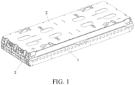
- a battery module provided by the embodiments of the present application includes a top plate 2, a bottom plate 3 arranged opposite to the top plate 2, two end plates 3 arranged opposite to each other, and two side plates 1 arranged opposite to each other.
- the two end plates 3 are connected to ends of the top plate 2 and the bottom plate 5. At least one of the two end plates 3 includes a plate body 31, two first plates 32, two second plates 33, and a hollow structure 34.
- the two first plates 32 are arranged opposite to each other and connected to two sides of the plate body 31.
- the two second plates 33 are arranged opposite to each other and connected to two sides of the plate body 31.
- the hollow structure 34 is located between the two first plates 32 and the two second plates 33.
- the hollow structure 34 includes a first hollow structure 341.
- the first hollow structure 341 includes a partition plate 3411 arranged opposite to the second plates 33 and a plurality of first reinforcing plates 3412 bent and connected to the partition plate 3411.
- the partition plate 3411, the plurality of first reinforcing plates 3412, the other one of the two second plates 33, and the two first plates 32 enclose a plurality of first reinforcing grooves 35.
- a surface of at least one of the first reinforcing plates 3412 connected to the partition plate 3411 is provided with at least one first connecting hole 343 penetrating through the surface to the other one of the second plates 33.
- the two side plates 1 are located between the two end plates 3 and connected to sides of the top plate 2 and the bottom plate 5. At least one of the two side plates 1 includes a base plate 11 and a base mounting plate 12.
- the base plate 11 includes a first surface 111 and a second surface 112 opposite to each other.
- the base plate 11 is provided with fixing holes 113 penetrating through the first surface 111 and the second surface 112.
- the base mounting plate 12 is bent and connected to the first surface 111.
- the base mounting plate 12 includes an outer connecting part 122 provided with at least one first mounting hole 1221.
- the top plate 2, the bottom plate 5, the two end plates 3, and the two side plates 1 enclose a battery compartment for mounting battery cells.
- the first connecting hole 343 of the end plates 3 is configured for a first fixing member to pass through to fix the end plates 3 on a case body of the battery pack.
- the first mounting hole 1221 of the side plates 1 is configured for a second fixing member to pass through to fix the side plates 1 on the case body of the battery pack. Both the first fixing member and the second fixing member include bolts.
- a battery module provided by some embodiments of the present application includes a top plate 2, a bottom plate 5, two side plates 1 arranged opposite to each other, and two end plates 3 arranged opposite to each other.
- the top plate 2 and the bottom plate 5 are arranged opposite to each other.
- the two side plates 1 are located between the top plate 2 and the bottom plate 5. Upper and lower ends of each of the side plates 1 are bolted to connect the top plate 2 and the bottom plate 5.
- the two end plates 3 are located between the top plate 2 and the bottom plate 5. Upper and lower ends of each of the end plates 3 are welded with the top plate 2 and the bottom plate 5. Left and right ends of each of the end plates 3 are riveted with the two side plates 1.
- the top plate 2, the bottom plate 5, the two end plates 3, and the two end plates 1 enclose a battery compartment for mounting battery cells.
- a plurality of buffer foams 6 are arranged side by side inside the battery compartment.
- a single battery cell is mounted between the adjacent two of the buffer foams 6.
- the buffer foams 6 are configured to provide a pre-tightening force of the battery module.
- the top plate 2 includes a cover body 21, at least one pressing member 22, a wire harness mounting member, a marking member 24, a buffer member, and an insulating film.
- the cover body 21 includes a first cover surface 211 and a second cover surface 212 arranged opposite to each other.
- the first cover surface 211 includes a central region, two first regions, and two second regions.
- the two first regions are respectively located at two ends of the central region, and the two second regions are respectively located at two ends of the first region away from the central region.
- Two edges of the cover body 21 along a width direction are both provided with two first avoidance grooves 215 penetrating through the first cover surface 211 and the second cover surface 212.
- Four first avoidance grooves 215 are arranged in pairs with respect to the width direction and a length direction of the cover body 21, and are evenly distributed in the two second regions.
- the pressing member 22 includes two pressing plates 221 arranged opposite to each other.
- Each of the two pressing plates 221 includes a bending part 2211 and a pressing part 2212 connected to one end of the bending part 2211, and the other end of the bending part 2211 is connected to a groove wall of a corresponding one of the first avoidance grooves 215.
- the pressing part 2212 protrudes from the first cover surface 211.
- the two pressing plates 221 and the groove wall of the corresponding one of the first avoidance grooves 215 surround a first mounting cavity 222 for accommodating output terminals of a circuit board.
- the first mounting cavity 222 is capable of better fixing the output terminals of the circuit board.
- the second cover surface 212 can be adhered to a surface of the battery cells of the battery module.
- the first mounting cavity 22 can provide a sufficient anti-expansion force to the battery cells.
- the pressing part 2212 is provided with a limiting groove 223 communicated to the first mounting cavity 222.
- the limiting groove 223 is configured for an extending part of a cells contact system (CCS) bracket to extend into it, thereby further playing a limiting role.
- CCS cells contact system
- the two edges of the cover body 21 along the width direction are both provided with a plurality of first riveting holes 213 penetrating through the first cover surface 211 and the second cover surface 212.
- the first riveting holes 213 are configured to rivet the side plates 1 of the battery module.
- Two edges of the cover body 21 along the length direction are provided with a first positioning hole 214, and the first positioning hole 214 is configured to fix a relative position between the end plates 3 and the cover body 21 of the battery module before the end plates 3 and the cover body 21 are welded.
- the marking member 24 includes two marking grooves 241 formed on the first cover surface 211 and arranged opposite to each other. There are four marking members 24. Two of the marking members 24 are located in the central region and arranged opposite to each other along the width direction of the cover body 21, and the other two of the marking members 24 are respectively located in the two second regions and arranged opposite to each other along the length direction of the cover body 21.
- the two marking grooves 241 of each of the marking members 24 define a region for mounting the buffer member.
- the buffer members are mounted on the first cover surface 211 and cover the marking grooves 241. Virtual connecting lines between the four buffer members form a diamond shape.
- the buffer members can absorb part of amplitude between the buffer members and an outer case cover to ensure the flatness of an upper cover as much as possible.
- the buffer members are the buffer foams 6, and are disposed on the first cover surface 211 by adhesion.
- Both the two first regions and the two second regions are provided with two weight reduction holes 4 oppositely arranged along the width direction of the cover body 21.
- the weight reduction holes 4 penetrate through the first cover surface 211 and the second cover surface 212.
- the two weight reduction holes 4 located on the first regions are located between two of the wire harness mounting frames 23.
- the weight reduction holes 4 can play a role in lightweighting the cover body 21.
- the insulating film is disposed on the second cover surface 212 by a hot pressing process.
- the insulating film is exposed by the four weight reduction holes 4.
- the insulating film is a black PET film.
- the two first regions are respectively provided with a positive electrode mark and a negative electrode mark for personnel identification.
- the cover body 21 and the pressing member 22 are integrally formed, and the cover body 21 and the pressing member 22 are manufactured by a die stamping process.
- the first positioning hole 214 and the weight reduction holes 4 are stamped out at the same time, and the positive electrode mark, the negative electrode mark, and the marking grooves 241 are further formed by engraving.
- the base mounting part 121 is configured to support a bottom part of an output stage base 14.
- the fixing holes 113 are configured for the fixing member to pass through a side of the output stage base to pass through and fix the output stage base 14 on the base plate 11.
- An edge of the base plate 11 is provided with a second avoidance groove 114 penetrating through the first surface 111 and the second surface 112, and the second avoidance groove 114 is located on one side of the fixing holes 113 away from the base mounting portion 121.
- the second avoidance groove 114 is configured for a conductive row of the battery module to extend to connect to the output stage base 14.
- the outer connecting part 122 is provided with two first mounting holes 1221 and an auxiliary hole 1222.
- the first mounting holes 1221 are configured to bolt connect the crossbeams to which the battery module is mounted.
- the auxiliary hole 1222 is located at one end of one of the first mounting holes 1221 away from the other one of the first mounting holes 1221.
- the crossbeams on which the battery module is mounted are located below the base mounting plate 12, and the auxiliary hole 1222 is configured to expose a relative position between the side plates 1 and the crossbeams on which the battery module is mounted, so that the battery module and the crossbeams are accurately mounted.
- the auxiliary hole 1222 can further provide a fixed position when the battery module is hoisted.
- the connecting plate 13 is located on one side of the fixing holes 113 facing away from the base mounting plate 12, and is bent and connected to an edge of the second surface 112 and extends in a direction facing away from the base mounting plate 12.
- the connecting plate 13 is provided with a plurality of second connecting holes 132 for bolt connecting the top plate 2 of the battery module.
- the connecting plate 13 is further provided with a second weight reduction groove 131 corresponding to the first weight reduction groove 123, and a width of the first weight reduction groove 123 is less than a width of the second weight reduction groove 131.
- the base plate 11, the base mounting plate 12, and the connecting plate 13 are integrally formed.
- the base plate 11, the base mounting plate 12, and the connecting plate 13 are formed by an aluminum extrusion process to reduce the use of materials, thereby reducing the cost, and realizing the lightweight of the base mounting plate 12.
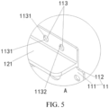
- a hole wall of each of the fixing holes 113 includes two arc-shaped walls 1131 arranged opposite to each other and two flat walls 1132 arranged opposite to each other. Each of the flat walls 1132 is located between the two arc-shaped walls 1131 and connected to the two arc-shaped walls 1131.
- the hotmelt fixing member extends from one end of the second surface 112 to fill the fixing holes 113 and covers the second surface 112, and abuts against the second surface 112 after being cured, so as to realize the function of stable installation of the output stage base.
- the flat walls 1132 are perpendicular to the base mounting plate 12, so that one end of the hot-melted fixing member fills the fixing holes 113 better by gravity, thereby eliminating the phenomenon that the output stage base can not be jammed in and tightly jammed in the related art.
- each of the end plates 3 includes a plate body 31.
- the plate body 31 includes a hollow structure 34.
- the hollow structure 34 includes a first hollow structure 341, a second hollow structure 342, two first plates 32, and two second plates 33.
- the plate body 31 includes a first part 311 and a second part 312.
- the two first plates 32 and the two second plates 33 are perpendicular to the plate body 31.
- the two first plates 32 are oppositely arranged along a first direction of the plate body 31 and connected to two ends of the first part 311.
- the two second plates 33 are oppositely arranged along a second direction of the plate body 31 and connected to two sides of the first part 311.
- the two second plates 33 are located between the two first plates 32.
- the first direction of the plate body 31 is a length direction of the plate body 31, and the second direction of the plate body 31 is a width direction of the plate body 31.
- the second part 312 is parallel to the first part 311 and connected to one side of the first part 311.
- Both the first hollow structure 341 and the second hollow structure 342 are located on the first part 311.
- the first hollow structure 341 is provided with a plurality of first reinforcing grooves 35
- the second hollow structure 342 is provided with a plurality of second reinforcing grooves 36.
- the second part 312 is provided with a mounting groove 3121 facing the second plate 33 adjacent to the second part 312, and the mounting groove 3121 is configured to embed the outer bracket for mounting the battery module.
- a groove bottom of the mounting groove 3121 is provided with a plurality of third reinforcing grooves 31211 arranged along the first direction of the plate body 31 to further realize the lightweight of the end plates 3.
- a plurality of second hollow structures 342 are provided, and all the second hollow structures 342 are located in the second mounting region.
- the second hollow structure 342 includes a plurality of second reinforcing plates 3421 and a plurality of booster plates 3422.
- the plurality of second reinforcing plates 3421 are connected between the second plate 33 adjacent to the second mounting region and the partition plate 3411.
- the plurality of second reinforcing plates 3421, the partition plate 3411, and the second plate 33 adjacent to the second mounting region enclose the second reinforcing grooves 36.
- At least two second hollow structures 342 are arranged at intervals along the first direction of the plate body 31. Two of the second hollow structures 342 enclose a second mounting cavity 37 communicated to the corresponding first connecting hole 343.
- a width of one end of the second reinforcing plate 3421 adjacent to the first reinforcing plate 3412 is greater than a width of one end of the second reinforcing plate 3421 away from the first reinforcing plate 3412. That is, the second reinforcing plate 3421 adopts a trapezoidal structure to achieve the lightweight of the end plates 3.
- the plurality of booster plates 3422 are provided in the second reinforcing grooves 36, and serve to further increase the anti-expansion force of the plate body 31.
- a surface of the first part 311 facing away from the hollow structure 34 is configured for foam bonding.
- the surface of the first part 311 facing away from the hollow structure 34 is provided with a first glue overflow groove 313, and the first glue overflow groove 313 is adjacent to an edge of one side of the plate body 31. That is, the first glue overflow groove 313 is located at an edge of the first part 311 away from the second part 312 and configured for accommodating an overflow glue for bonding a foam.
- One side of the second part 312 facing away from the hollow structure 34 is provided with a baffle plate 315 protruding from a surface of the second part 312.
- the baffle plate 315 is provided at the edge of the other side of the plate body 31, that is, the edge of the second part 312 away from the first part 311.
- the baffle plate 315 is configured to restrict the movement of the foam.
- One end of the baffle plate 315 away from the second part 312 is provided with a second glue overflow groove 314.
- the second glue overflow groove 314 is generally located below the first glue overflow groove 313.
- the second glue overflow groove 314 can collect part of the glue liquid flowing out of the foam under the action of gravity.
- the second plate 33 away from the second part 312 is configured for welding the top plate 2 of the battery module.
- the above-mentioned second plates 33 and the baffle plate 315 are both provided with a second positioning hole 38 penetrating the second plates 3 and the baffle plate 315.
- One end of the baffle plate 315 facing away from the second plates 3 is configured for welding the bottom plate 5 of the battery module.
- the second positioning hole 38 is configured to define a position between the end plates 3 and the top plate 2 when welding the end plates 3 and the bottom plate 5 and when welding the end plates 3 and the bottom plate 5, thereby improving welding accuracy.
- the end plates 3 generally adopt an aluminum extrusion process. After extrusion molding, the end plates 3 are machined to form grooves or holes to achieve cooperation with other structures. In addition, a traceability code containing processing information is added to the end plates 3 by machining.
- the plate body 31 and the baffle plate 315 are integrally formed, and the end plates 3 are formed through a mold by an aluminum casting process to form the plate body 31 and the baffle plate 315. Different traceability codes are formed by changing the insert of the mold in the casting process.
- the first reinforcing grooves 35, the second reinforcing grooves 36, the first connecting hole 343, the second mounting hole 321, the second mounting cavity 37, and the second positioning hole 38 are simultaneously formed in the casting process, without additional machining opening, and the processing steps are reduced.
- a thickness of the foams bonded to the plate body 31 is compressed from 3 mm to 2 mm, thereby acting as a buffer for the battery cells of the battery module.
- a battery pack further provided by the embodiments of the present application includes the battery module mentioned above, a first fixing member, a second fixing member, and a case body. Both the first fixing member and the second fixing member adopt bolts.
- a vehicle further provided by the embodiments of the present application includes a battery pack above mentioned.
Landscapes
- Chemical & Material Sciences (AREA)
- Chemical Kinetics & Catalysis (AREA)
- Electrochemistry (AREA)
- General Chemical & Material Sciences (AREA)
- Engineering & Computer Science (AREA)
- Aviation & Aerospace Engineering (AREA)
- Battery Mounting, Suspending (AREA)
Abstract
A battery module includes a top plate (2), a bottom plate (5), two end plates (3), and two side plates (1). At least one of the two end plates (3) includes a plate body (31) including a hollow structure (34) provided with first reinforcing grooves (35) and a first connecting hole (343). At least one of the two side plates (1) includes a base plate (11) and a base mounting plate (12). The base plate (11) is provided with a fixing hole (113) penetrating through the base plate (11). The base mounting plate (12) is bent and connected to the base plate (11) and includes an outer connecting part (122) provided with a first mounting hole (1221). The first connecting hole (343) and the first mounting hole (1221) are configured for a first fixing member and a second fixing member to pass through, respectively.
Description
- The present application relates to a technical field of power batteries, and in particular, to battery modules, battery packs, and vehicles.
- Battery modules include a plurality of plate bodies and a plurality of battery cells. The plurality of battery cells are fixed inside battery compartments surrounded by the plurality of plate bodies. Due to different usage environments, a part of the battery modules needs to be fixed on crossbeams of battery packs by using the plate bodies. Therefore, the plate bodies need a certain mechanical strength to support the battery modules and high bending resistance, and further need to meet requirements of lightweight to reduce material costs. However, at present, the plate bodies of most battery modules are formed by aluminum extrusion process, which cannot be lightweight. In this case, it is inconvenient to provide holes which do not affect an anti-expansion force of the plate bodies to connect with the crossbeams of the battery packs. Therefore, it is necessary to provide a lightweight support structure with better supporting force.
- A battery module, a battery pack, and a vehicle provided by the embodiments of the present application improve a technical problem that it is difficult to balance between a mounting strength of the battery module and the lightweight of the battery module in the related art.
- In a first aspect, a battery module provided by the embodiments of the present application includes a top plate and a bottom plate arranged opposite to each other, two end plates arranged opposite to each other, and two side plates arranged opposite to each other. The two end plates are connected to ends of the top plate and the bottom plate. At least one of the two end plates includes a plate body. The plate body includes a hollow structure. The hollow structure is provided with a plurality of first reinforcing grooves and at least one first connecting hole. The at least one first connecting hole is configured to be mounted on an outer bracket for mounting the battery module. The plate body is an integrally formed structure. At least two of the first reinforcing grooves are arranged at intervals along a first direction of the plate body. The at least one first connecting hole is located between the two first reinforcing grooves and penetrates the plate body along a second direction of the plate body. The two side plates are arranged opposite to each other located between the two end plates and connected to sides of the top plate and the bottom plate. At least one of the two side plates includes a base plate and a base mounting plate. The base plate is provided with a fixing hole penetrating through the base plate. The base mounting plate is bent and connected to the base plate. The base mounting plate includes an outer connecting part provided with a first mounting hole. The top plate, the bottom plate, the two end plates, and the two side plates enclose a battery compartment for mounting battery cells. The at least one first connecting hole of the end plates is configured for a first fixing member to pass through to fix the end plates on a case body of the battery pack. The first mounting hole of the side plates is configured for a second fixing member to pass through to fix the side plates on the case body of the battery pack.
- In some embodiments, a connection force between the end plates and the case body of the battery pack is greater than a connection force between the side plates and the case body of the battery pack.
- In some embodiments, the at least one of the two end plates and the at least one of the two side plates are integrally formed.
- In some embodiments, at least one end of each of the side plates is provided with a second mounting hole communicated to a corresponding one of the first reinforcing grooves. An edge of the base plate of the side plates is provided with a second riveting hole arranged correspondingly to the second mounting hole. The second mounting hole and the second riveting hole are configured for a rivet to pass through.
- In some embodiments, the hollow structure of the side plates is further provided with a plurality of second reinforcing grooves. At least two of the second reinforcing grooves are arranged at intervals along the first direction of the plate body of the end plates. Two of the second reinforcing grooves arranged at intervals enclose a second mounting cavity, and the second mounting cavity is correspondingly communicated to the first connecting hole.
- In some embodiments, the hollow structure includes a first hollow structure and a second hollow structure. The first hollow structure includes a partition plate and a plurality of first reinforcing plates bent and connected to the partition plate. The partition plate and the plurality of first reinforcing plates enclose the plurality of first reinforcing grooves. The second hollow structure includes second reinforcing plates bent and connected to the partition plate and extending along a direction away from the first reinforcing plates. The second reinforcing plates and the partition plate enclose the second reinforcing grooves. A width of one end of each of the second reinforcing plates adjacent to the partition plate is greater than a width of one end of each of the second reinforcing plates away from the partition plate.
- In some embodiments, two edges of the two end plates are provided with an insulation groove penetrating through a surface of the end plates facing the battery compartment. The insulation groove is configured to embed folded edges of insulation sheets located inside the battery compartment and wrapped on the end plates. The insulation groove is shielded by the side plates.
- In some embodiments, the outer connecting part of the side plates is provided with an auxiliary hole. The auxiliary hole is configured to expose a relative position between the side plates and crossbeams on which the battery module is mounted.
- In some embodiments, the top plate includes a cover body and a pressing member. An edge of the cover body is provided with a first avoidance groove penetrating through the cover body. The pressing member includes two pressing plates arranged opposite to each other. Each of the two pressing plates comprises a bending part and a pressing part connected to one end of the bending part. The other end of the bending part is connected to a groove wall of the first avoidance groove. The pressing part protrudes from the cover body. The two pressing plates and the groove wall of the first avoidance groove enclose a first mounting cavity configured for accommodating output terminals of a circuit board.
- In a second aspect, a battery pack provided by the embodiments of the present application includes the battery module mentioned above, a first fixing member, a second fixing member, and a case body. The battery module is accommodated inside the case body, the first fixing member passes through the at least one first connecting hole of the end plates to fix the end plates on the case body. The second fixing member passes through the first mounting hole of the side plates to fix the side plates on the case body.
- In a third aspect, a vehicle provided by the embodiments of the present application includes the battery pack mentioned above.
- The beneficial effects of the present application are illustrated below. In the embodiments of the present application, by providing at least one first connecting hole on the end plates, and providing a first mounting hole on the side plates, the battery module can be mounted and fixed on crossbeams of the battery pack. In addition, the side plates include a plurality of first reinforcing grooves and a plurality of first reinforcing plate, which can reduce a weight of the end plates without reducing the bending resistance of the end plates themselves, thereby providing a lightweight battery module with a strong supporting force. Under a condition that an anti-expansion force of the battery module is ensured, it is convenient for mounting the battery module and realizing the lightweight of the battery module.
- In order to more clearly explain technical solutions in specific embodiments of the present application or the prior art, the drawings needed to be used in the description of the specific embodiments or the prior art will be briefly introduced below. It is obvious that the drawings in the following description illustrate some embodiments of the present application. For those of ordinary skill in the art, other drawings may be obtained based on these drawings without creative efforts.
-
FIG. 1 is a three-dimensional schematic view of a battery module according to an embodiment of the present application. -
FIG. 2 is an exploded view of the battery module according to an embodiment of the present application. -
FIG. 3 is a three-dimensional schematic view of a top plate according to an embodiment of the present application. -
FIG. 4 is a three-dimensional schematic view of a side plate according to an embodiment of the present application. -
FIG. 5 is an enlarged schematic view of a position A shown inFIG. 4 . -
FIG. 6 is a schematic structural view of the side plate and an output stage base according to an embodiment of the present application. -
FIG. 7 is a three-dimensional schematic view of the output stage base according to an embodiment of the present application. -
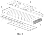
FIG. 8 is an exploded view from another perspective of the battery module according to an embodiment of the present application. -
FIG. 9 is a three-dimensional schematic view of an end plate according to an embodiment of the present application. -
FIG. 10 is a rear view of the end plate according to an embodiment of the present application. -
FIG. 11 is a front view of the end plate according to an embodiment of the present application. -
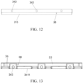
FIG. 12 is a bottom view of the end plate according to an embodiment of the present application. -
FIG. 13 is a top view of the end plate according to an embodiment of the present application. - 1, side plate; 2, 11, base plate; 111, first surface; 112, second surface; 113, fixing hole; 1131, arc-shaped wall; 1132, flat wall; 114, second avoidance groove; 115, second riveting hole; 12, base mounting plate; 121, base mounting part; 122, outer connecting part; 1221, first mounting hole; 1222, auxiliary hole; 123, first weight reduction groove; 13, connecting plate; 131, second weight reduction groove; 132, second connecting hole; 14, output stage base; 2, top plate; 21, cover body; 211, first cover surface; 212, second cover surface; 213, first riveting hole; 214, first positioning hole; 215, first avoidance groove; 22, pressing member; 221, pressing plate; 2211, bending part; 2212, pressing part; 222, first mounting cavity; 223, limiting groove; 23, wiring harness mounting frame; 231, connecting part; 232, fixing part; 233, accommodation groove; 24, marking member; 241, marking groove; 3, end plate; 31, plate body; 311, first part; 312, second part; 3121, mounting groove; 31211, third reinforcing groove; 313, first glue overflow groove; 314, second glue overflow groove; 315, baffle plate; 316, insulating groove; 32, first plate; 321, second mounting hole; 33, second plate; 34, hollow structure; 341, first hollow structure; 3411, partition plate; 3412, first reinforcing plate; 342, second hollow structure; 3421, second reinforcing plate; 3422, booster plate; 343, first connecting hole; 35, first reinforcing groove; 36, second reinforcing groove; 37, second mounting cavity; 38, second positioning hole; 4, weight reduction hole; 5, bottom plate; 6, buffer foam; 7, insulating sheet.
- The technical solutions of the present application will be clearly and completely described below with reference to the accompanying drawings. Obviously, the described embodiments are part of the embodiments of the present application, rather than all the embodiments. All other embodiments obtained by persons of ordinary skill in the art based on the embodiments of the present application without creative efforts shall fall within the protection scope of the present application. In addition, it should be understood that the specific embodiments described herein are merely for illustration and explanation of the present application, and are not intended to limit the present application. In the present application, in the absence of a contrary explanation, the orientational terms, such as "up" and "down", generally refer to the upper and lower in the actual use or working state of the device, specifically the drawing direction in the attached drawings; While "inner" and "outer" are for the outline of the device.
- Referring to
FIG. 1 to FIG. 13 , a battery module provided by the embodiments of the present application includes atop plate 2, abottom plate 3 arranged opposite to thetop plate 2, twoend plates 3 arranged opposite to each other, and twoside plates 1 arranged opposite to each other. - The two
end plates 3 are connected to ends of thetop plate 2 and thebottom plate 5. At least one of the twoend plates 3 includes aplate body 31, twofirst plates 32, twosecond plates 33, and ahollow structure 34. The twofirst plates 32 are arranged opposite to each other and connected to two sides of theplate body 31. The twosecond plates 33 are arranged opposite to each other and connected to two sides of theplate body 31. Thehollow structure 34 is located between the twofirst plates 32 and the twosecond plates 33. Thehollow structure 34 includes a firsthollow structure 341. The firsthollow structure 341 includes apartition plate 3411 arranged opposite to thesecond plates 33 and a plurality of first reinforcingplates 3412 bent and connected to thepartition plate 3411. Thepartition plate 3411, the plurality of first reinforcingplates 3412, the other one of the twosecond plates 33, and the twofirst plates 32 enclose a plurality of first reinforcinggrooves 35. A surface of at least one of the first reinforcingplates 3412 connected to thepartition plate 3411 is provided with at least one first connectinghole 343 penetrating through the surface to the other one of thesecond plates 33. - The two
side plates 1 are located between the twoend plates 3 and connected to sides of thetop plate 2 and thebottom plate 5. At least one of the twoside plates 1 includes abase plate 11 and abase mounting plate 12. Thebase plate 11 includes afirst surface 111 and asecond surface 112 opposite to each other. Thebase plate 11 is provided with fixingholes 113 penetrating through thefirst surface 111 and thesecond surface 112. Thebase mounting plate 12 is bent and connected to thefirst surface 111. Thebase mounting plate 12 includes an outer connectingpart 122 provided with at least onefirst mounting hole 1221. Thetop plate 2, thebottom plate 5, the twoend plates 3, and the twoside plates 1 enclose a battery compartment for mounting battery cells. - The first connecting
hole 343 of theend plates 3 is configured for a first fixing member to pass through to fix theend plates 3 on a case body of the battery pack. Thefirst mounting hole 1221 of theside plates 1 is configured for a second fixing member to pass through to fix theside plates 1 on the case body of the battery pack. Both the first fixing member and the second fixing member include bolts. - Referring to
FIG. 1 andFIG. 2 , a battery module provided by some embodiments of the present application includes atop plate 2, abottom plate 5, twoside plates 1 arranged opposite to each other, and twoend plates 3 arranged opposite to each other. - The
top plate 2 and thebottom plate 5 are arranged opposite to each other. The twoside plates 1 are located between thetop plate 2 and thebottom plate 5. Upper and lower ends of each of theside plates 1 are bolted to connect thetop plate 2 and thebottom plate 5. The twoend plates 3 are located between thetop plate 2 and thebottom plate 5. Upper and lower ends of each of theend plates 3 are welded with thetop plate 2 and thebottom plate 5. Left and right ends of each of theend plates 3 are riveted with the twoside plates 1. Thetop plate 2, thebottom plate 5, the twoend plates 3, and the twoend plates 1 enclose a battery compartment for mounting battery cells. - A plurality of buffer foams 6 are arranged side by side inside the battery compartment. A single battery cell is mounted between the adjacent two of the buffer foams 6. The buffer foams 6 are configured to provide a pre-tightening force of the battery module.
- Referring to
FIG. 2 andFIG. 3 , thetop plate 2 includes acover body 21, at least one pressingmember 22, a wire harness mounting member, a marking member 24, a buffer member, and an insulating film. - The
cover body 21 includes afirst cover surface 211 and asecond cover surface 212 arranged opposite to each other. Thefirst cover surface 211 includes a central region, two first regions, and two second regions. The two first regions are respectively located at two ends of the central region, and the two second regions are respectively located at two ends of the first region away from the central region. Two edges of thecover body 21 along a width direction are both provided with twofirst avoidance grooves 215 penetrating through thefirst cover surface 211 and thesecond cover surface 212. Fourfirst avoidance grooves 215 are arranged in pairs with respect to the width direction and a length direction of thecover body 21, and are evenly distributed in the two second regions. - The pressing
member 22 includes twopressing plates 221 arranged opposite to each other. Each of the twopressing plates 221 includes abending part 2211 and apressing part 2212 connected to one end of thebending part 2211, and the other end of thebending part 2211 is connected to a groove wall of a corresponding one of thefirst avoidance grooves 215. Thepressing part 2212 protrudes from thefirst cover surface 211. The twopressing plates 221 and the groove wall of the corresponding one of thefirst avoidance grooves 215 surround a first mountingcavity 222 for accommodating output terminals of a circuit board. The first mountingcavity 222 is capable of better fixing the output terminals of the circuit board. Furthermore, thesecond cover surface 212 can be adhered to a surface of the battery cells of the battery module. Compared with a structure of thecover body 21 in the related art, the first mountingcavity 22 can provide a sufficient anti-expansion force to the battery cells. Thepressing part 2212 is provided with a limitinggroove 223 communicated to the first mountingcavity 222. The limitinggroove 223 is configured for an extending part of a cells contact system (CCS) bracket to extend into it, thereby further playing a limiting role. - The two edges of the
cover body 21 along the width direction are both provided with a plurality of firstriveting holes 213 penetrating through thefirst cover surface 211 and thesecond cover surface 212. The firstriveting holes 213 are configured to rivet theside plates 1 of the battery module. Two edges of thecover body 21 along the length direction are provided with afirst positioning hole 214, and thefirst positioning hole 214 is configured to fix a relative position between theend plates 3 and thecover body 21 of the battery module before theend plates 3 and thecover body 21 are welded. - The wire
harness mounting frame 23 includes two connectingparts 231 arranged opposite to each other, a fixingpart 232 connected between the two connectingparts 231, and a fixing bolt. The two connectingparts 231 are connected to thefirst cover surface 211. The fixingpart 232 and thecover body 21 enclose anaccommodation groove 233 for accommodating a wire harness. The fixing bolt is screwed to the fixingpart 232 and extends into theaccommodation groove 233 to press the wire harness. In other embodiments, the fixing bolt may further be replaced with a cable tie. The wire harness is tied to the fixingpart 232 by the cable tie to realize the installation and fixation of the wire harness. Four wireharness mounting frames 23 are arranged evenly in the two first regions. Two of the four wireharness mounting frames 23 on each of the first regions are arranged opposite to each other with respect to the width direction of thecover body 21. The two of the wireharness mounting frames 23 on different first regions are arranged opposite to each other with respect to the center region. - The marking member 24 includes two marking
grooves 241 formed on thefirst cover surface 211 and arranged opposite to each other. There are four marking members 24. Two of the marking members 24 are located in the central region and arranged opposite to each other along the width direction of thecover body 21, and the other two of the marking members 24 are respectively located in the two second regions and arranged opposite to each other along the length direction of thecover body 21. The two markinggrooves 241 of each of the marking members 24 define a region for mounting the buffer member. - There are four buffer members in one-to-one correspondence to the four marking members 24. The buffer members are mounted on the
first cover surface 211 and cover the markinggrooves 241. Virtual connecting lines between the four buffer members form a diamond shape. The buffer members can absorb part of amplitude between the buffer members and an outer case cover to ensure the flatness of an upper cover as much as possible. In this embodiment, the buffer members are the buffer foams 6, and are disposed on thefirst cover surface 211 by adhesion. - Both the two first regions and the two second regions are provided with two
weight reduction holes 4 oppositely arranged along the width direction of thecover body 21. Theweight reduction holes 4 penetrate through thefirst cover surface 211 and thesecond cover surface 212. The twoweight reduction holes 4 located on the first regions are located between two of the wire harness mounting frames 23. Theweight reduction holes 4 can play a role in lightweighting thecover body 21. - The insulating film is disposed on the
second cover surface 212 by a hot pressing process. The insulating film is exposed by the four weight reduction holes 4. The insulating film is a black PET film. - The two first regions are respectively provided with a positive electrode mark and a negative electrode mark for personnel identification.
- The
cover body 21 and the pressingmember 22 are integrally formed, and thecover body 21 and the pressingmember 22 are manufactured by a die stamping process. Thefirst positioning hole 214 and theweight reduction holes 4 are stamped out at the same time, and the positive electrode mark, the negative electrode mark, and the markinggrooves 241 are further formed by engraving. - Referring to
FIG. 4 ,FIG. 5 ,FIG. 6, and FIG. 7 , one of theside plates 1 includes abase plate 11, abase mounting plate 12, and a connectingplate 13. - Specifically, two opposite sides of the
base plate 11 are configured for bolt connecting to thetop plate 2 and thebottom plate 5 of the battery module. The two opposite ends of thebase plate 11 are provided with a plurality of secondriveting holes 115, and the secondriveting holes 115 are configured for riveting with the twoopposite end plates 3 of the battery module. Thebase plate 11 includes afirst surface 111 and asecond surface 112 arranged opposite to each other. Both thefirst surface 111 and thesecond surface 112 are connected to the two opposite sides and the two opposite ends of thebase plate 11. Thebase plate 11 is provided with four fixingholes 113 penetrating through thefirst surface 111 and thesecond surface 112. Two of the fixingholes 113 are adjacent to one of the two opposite ends of thebase plate 11, and the other two of the fixingholes 113 are adjacent to the other one of the two opposite ends of thebase plate 11. Thebase plate 11 is further provided with theweight reduction holes 4 penetrating through thefirst surface 111 and thesecond surface 112. In another embodiment, thebase plate 11 is further provided with the insulating film formed on thesecond surface 112 by cold pressing, and the insulating film is exposed by the weight reduction holes 4. - The
base mounting plate 12 includes twobase mounting parts 121 arranged opposite to each other and an outer connectingpart 122 located between the twobase mounting parts 121. The twobase mounting parts 121 correspond to the fixingholes 113 adjacent to the two opposite ends of thebase plate 11, respectively. Both thebase mounting parts 121 and the outer connectingpart 122 are bent and connected to thefirst surface 111 of one of theside plates 1. A firstweight reduction groove 123 is provided between thebase mounting part 121 and the outer connectingpart 122. - The
base mounting part 121 is configured to support a bottom part of anoutput stage base 14. The fixing holes 113 are configured for the fixing member to pass through a side of the output stage base to pass through and fix theoutput stage base 14 on thebase plate 11. An edge of thebase plate 11 is provided with asecond avoidance groove 114 penetrating through thefirst surface 111 and thesecond surface 112, and thesecond avoidance groove 114 is located on one side of the fixingholes 113 away from thebase mounting portion 121. Thesecond avoidance groove 114 is configured for a conductive row of the battery module to extend to connect to theoutput stage base 14. - The outer connecting
part 122 is provided with two first mountingholes 1221 and anauxiliary hole 1222. The first mountingholes 1221 are configured to bolt connect the crossbeams to which the battery module is mounted. Theauxiliary hole 1222 is located at one end of one of the first mountingholes 1221 away from the other one of the first mounting holes 1221. When the battery module is mounted, the crossbeams on which the battery module is mounted are located below thebase mounting plate 12, and theauxiliary hole 1222 is configured to expose a relative position between theside plates 1 and the crossbeams on which the battery module is mounted, so that the battery module and the crossbeams are accurately mounted. In addition, theauxiliary hole 1222 can further provide a fixed position when the battery module is hoisted. - The connecting
plate 13 is located on one side of the fixingholes 113 facing away from thebase mounting plate 12, and is bent and connected to an edge of thesecond surface 112 and extends in a direction facing away from thebase mounting plate 12. The connectingplate 13 is provided with a plurality of second connectingholes 132 for bolt connecting thetop plate 2 of the battery module. The connectingplate 13 is further provided with a secondweight reduction groove 131 corresponding to the firstweight reduction groove 123, and a width of the firstweight reduction groove 123 is less than a width of the secondweight reduction groove 131. Thebase plate 11, thebase mounting plate 12, and the connectingplate 13 are integrally formed. Thebase plate 11, thebase mounting plate 12, and the connectingplate 13 are formed by an aluminum extrusion process to reduce the use of materials, thereby reducing the cost, and realizing the lightweight of thebase mounting plate 12. - Referring to
FIG. 8 , the other one of theside plates 1 is different from theside plate 1 mentioned above in that thebase mounting plate 12 and the avoidance grooves are not included. In addition, there are two outer connectingparts 122 and three firstweight reduction grooves 123. One of the firstweight reduction grooves 123 is located between the two outer connectingparts 122 and does not correspond to the secondweight reduction groove 131, and the other two of the firstweight reduction grooves 123 are located on two sides of the two outer connectingparts 122 and correspond to the secondweight reduction groove 131. Each of the two outer connectingparts 122 is provided with onefirst mounting hole 1221, and each of the two outer connectingparts 122 is provided with oneauxiliary hole 1222. - Referring to
FIG. 5 , a hole wall of each of the fixing holes 113 includes two arc-shapedwalls 1131 arranged opposite to each other and twoflat walls 1132 arranged opposite to each other. Each of theflat walls 1132 is located between the two arc-shapedwalls 1131 and connected to the two arc-shapedwalls 1131. When the fixingholes 113 are passed through by the fixing member of the side of the output stage base, the hotmelt fixing member extends from one end of thesecond surface 112 to fill the fixingholes 113 and covers thesecond surface 112, and abuts against thesecond surface 112 after being cured, so as to realize the function of stable installation of the output stage base. Theflat walls 1132 are perpendicular to thebase mounting plate 12, so that one end of the hot-melted fixing member fills the fixingholes 113 better by gravity, thereby eliminating the phenomenon that the output stage base can not be jammed in and tightly jammed in the related art. - Referring to
FIG. 9 ,FIG. 10, and FIG. 11 , each of theend plates 3 includes aplate body 31. Theplate body 31 includes ahollow structure 34. Thehollow structure 34 includes a firsthollow structure 341, a secondhollow structure 342, twofirst plates 32, and twosecond plates 33. - The
plate body 31 includes afirst part 311 and asecond part 312. The twofirst plates 32 and the twosecond plates 33 are perpendicular to theplate body 31. The twofirst plates 32 are oppositely arranged along a first direction of theplate body 31 and connected to two ends of thefirst part 311. The twosecond plates 33 are oppositely arranged along a second direction of theplate body 31 and connected to two sides of thefirst part 311. The twosecond plates 33 are located between the twofirst plates 32. The first direction of theplate body 31 is a length direction of theplate body 31, and the second direction of theplate body 31 is a width direction of theplate body 31. Thesecond part 312 is parallel to thefirst part 311 and connected to one side of thefirst part 311. Both the firsthollow structure 341 and the secondhollow structure 342 are located on thefirst part 311. The firsthollow structure 341 is provided with a plurality of first reinforcinggrooves 35, and the secondhollow structure 342 is provided with a plurality of second reinforcinggrooves 36. Thesecond part 312 is provided with a mountinggroove 3121 facing thesecond plate 33 adjacent to thesecond part 312, and the mountinggroove 3121 is configured to embed the outer bracket for mounting the battery module. A groove bottom of the mountinggroove 3121 is provided with a plurality of third reinforcinggrooves 31211 arranged along the first direction of theplate body 31 to further realize the lightweight of theend plates 3. - The first
hollow structure 341 includes apartition plate 3411 and a plurality of first reinforcingplates 3412. Thepartition plate 3411 is disposed opposite to one of thesecond plates 33. Thepartition plate 3411 is located between the twofirst plates 32 and divides thefirst part 311 into a first mounting region and a second mounting region. The first mounting region is located at one side of the second mounting region adjacent to thesecond part 312. The plurality of first reinforcingplates 3412 are bent and connected to thepartition plate 3411. The plurality of first reinforcingplates 3412, thepartition plate 3411, and thesecond plate 33 adjacent to thesecond part 312 enclose the plurality of first reinforcinggrooves 35. Through the first reinforcinggrooves 35, the lightweight design of theend plates 3 of the battery module is realized without sacrificing the anti-expansion force of the battery module. - A surface of at least one of the first reinforcing
plates 3412 connected to thepartition plate 3411 is provided with a first connectinghole 343. The first connectinghole 343 penetrates through the surface to thesecond plate 33 adjacent to thesecond part 312, and the first connectinghole 343 is configured to mount the outer bracket for mounting the battery module. The twofirst plates 32 are both provided with asecond mounting hole 321, and thesecond mounting hole 321 is configured for mounting theside plates 1 of the battery module. Thesecond mounting hole 321 is communicated to a corresponding one of the first reinforcinggrooves 35. Theplate body 31 has an integrally molded structure. - A plurality of second
hollow structures 342 are provided, and all the secondhollow structures 342 are located in the second mounting region. The secondhollow structure 342 includes a plurality of second reinforcingplates 3421 and a plurality ofbooster plates 3422. The plurality of second reinforcingplates 3421 are connected between thesecond plate 33 adjacent to the second mounting region and thepartition plate 3411. The plurality of second reinforcingplates 3421, thepartition plate 3411, and thesecond plate 33 adjacent to the second mounting region enclose the second reinforcinggrooves 36. At least two secondhollow structures 342 are arranged at intervals along the first direction of theplate body 31. Two of the secondhollow structures 342 enclose a second mountingcavity 37 communicated to the corresponding first connectinghole 343. When thefirst connection hole 343 is configured for mounting the outer bracket for mounting the battery module, bolt used can extend into thefirst connection hole 343 through the second mountingcavity 37, thereby improving the convenience of mounting. - A width of one end of the second reinforcing
plate 3421 adjacent to the first reinforcingplate 3412 is greater than a width of one end of the second reinforcingplate 3421 away from the first reinforcingplate 3412. That is, the second reinforcingplate 3421 adopts a trapezoidal structure to achieve the lightweight of theend plates 3. The plurality ofbooster plates 3422 are provided in the second reinforcinggrooves 36, and serve to further increase the anti-expansion force of theplate body 31. - Referring to
FIG. 10 , a surface of thefirst part 311 facing away from thehollow structure 34 is configured for foam bonding. The surface of thefirst part 311 facing away from thehollow structure 34 is provided with a firstglue overflow groove 313, and the firstglue overflow groove 313 is adjacent to an edge of one side of theplate body 31. That is, the firstglue overflow groove 313 is located at an edge of thefirst part 311 away from thesecond part 312 and configured for accommodating an overflow glue for bonding a foam. - One side of the
second part 312 facing away from thehollow structure 34 is provided with abaffle plate 315 protruding from a surface of thesecond part 312. Thebaffle plate 315 is provided at the edge of the other side of theplate body 31, that is, the edge of thesecond part 312 away from thefirst part 311. Thebaffle plate 315 is configured to restrict the movement of the foam. One end of thebaffle plate 315 away from thesecond part 312 is provided with a secondglue overflow groove 314. During the actual use of theend plates 3, the secondglue overflow groove 314 is generally located below the firstglue overflow groove 313. The secondglue overflow groove 314 can collect part of the glue liquid flowing out of the foam under the action of gravity. - A surface of the
plate body 31 facing away from thehollow structure 34 is provided with two insulatinggrooves 316. The twoinsulating grooves 316 are respectively located at two ends of theplate body 31, and the insulatinggrooves 316 are embedded with insulatingsheets 7 wrapped on the foams. In actual assembly, after the insulatingsheets 7 are bonded to the foams, theend plates 3 are mounted with other battery modules before the colloid is cured. In this case, the insulatingsheets 7 are easy to slide and displace, which affects the insulating effect. A folded edge of the insulatingsheets 7 is put into the insulatinggrooves 316 to play a limiting role on the insulatingsheets 7. - Referring to
FIG. 12 and FIG. 13 , thesecond plate 33 away from thesecond part 312 is configured for welding thetop plate 2 of the battery module. The above-mentionedsecond plates 33 and thebaffle plate 315 are both provided with asecond positioning hole 38 penetrating thesecond plates 3 and thebaffle plate 315. One end of thebaffle plate 315 facing away from thesecond plates 3 is configured for welding thebottom plate 5 of the battery module. Thesecond positioning hole 38 is configured to define a position between theend plates 3 and thetop plate 2 when welding theend plates 3 and thebottom plate 5 and when welding theend plates 3 and thebottom plate 5, thereby improving welding accuracy. - In this embodiment, the
end plates 3 generally adopt an aluminum extrusion process. After extrusion molding, theend plates 3 are machined to form grooves or holes to achieve cooperation with other structures. In addition, a traceability code containing processing information is added to theend plates 3 by machining. However, in the present application, theplate body 31 and thebaffle plate 315 are integrally formed, and theend plates 3 are formed through a mold by an aluminum casting process to form theplate body 31 and thebaffle plate 315. Different traceability codes are formed by changing the insert of the mold in the casting process. The first reinforcinggrooves 35, the second reinforcinggrooves 36, the first connectinghole 343, thesecond mounting hole 321, the second mountingcavity 37, and thesecond positioning hole 38 are simultaneously formed in the casting process, without additional machining opening, and the processing steps are reduced. - When the battery module is mounted completely, a thickness of the foams bonded to the
plate body 31 is compressed from 3 mm to 2 mm, thereby acting as a buffer for the battery cells of the battery module. - A battery pack further provided by the embodiments of the present application includes the battery module mentioned above, a first fixing member, a second fixing member, and a case body. Both the first fixing member and the second fixing member adopt bolts.
- A vehicle further provided by the embodiments of the present application includes a battery pack above mentioned.
- The embodiments of the present application are described in detail above. The principle and implementations of the present application are described in this specification by using specific examples. The description about the foregoing embodiments is merely provided to help understand the method and core ideas of the present application. In addition, persons of ordinary skill in the art can make modifications in terms of the specific implementations and application scopes according to the ideas of the present application. Therefore, the content of this specification shall not be construed as a limit to the present application.
Claims (15)
- A battery module, characterized in that the battery module comprises:a top plate (2);a bottom plate (5) arranged opposite to the top plate (2);two end plates (3) arranged opposite to each other, connected to ends of the top plate (2) and the bottom plate (5), wherein at least one of the two end plates (3) comprises a plate body (31), the plate body (31) comprises a hollow structure (34), the hollow structure (34) is provided with a plurality of first reinforcing grooves (35) and at least one first connecting hole (343), and the at least one first connecting hole (343) is configured to be mounted on an outer bracket for mounting the battery module; andtwo side plates (1) arranged opposite to each other, located between the two end plates (3) and connected to sides of the top plate (2) and the bottom plate (5), wherein at least one of the two side plates (1) comprises a base plate (11) and a base mounting plate (12), the base plate (11) is provided with a fixing hole (113) penetrating through the base plate (11), the base mounting plate (12) is bent and connected to the base plate (11), the base mounting plate (12) comprises an outer connecting part (122) provided with a first mounting hole (1221), and the top plate (2), the bottom plate (5), the two end plates (3), and the two side plates (1) enclose a battery compartment for mounting battery cells;wherein the plate body (31) is an integrally formed structure, at least two of the first reinforcing grooves (35) are arranged at intervals along a first direction of the plate body (31), and the at least one first connecting hole (343) is located between the two first reinforcing grooves (35) and penetrates through the plate body (31) along a second direction of the plate body (31); andwherein the at least one first connecting hole (343) of the end plates (3) is configured for a first fixing member to pass through to fix the end plates (3) on a case body of the battery pack, and the first mounting hole (1221) of the side plates (1) is configured for a second fixing member to pass through to fix the side plates (1) on the case body of the battery pack.
- The battery module according to claim 1, characterized in that a connection force between the end plates (3) and the case body of the battery pack is greater than a connection force between the side plates (1) and the case body of the battery pack.
- The battery module according to claim 1, characterized in that the at least one of the two end plates (3) and the at least one of the two side plates (1) are integrally formed.
- The battery module according to claim 1, characterized in that at least one end of each of the side plates (1) is provided with a second mounting hole (321) communicated to a corresponding one of the first reinforcing grooves (35), an edge of the base plate (11) of the side plates (1) is provided with a second riveting hole (115) arranged correspondingly to the second mounting hole (321), and the second mounting hole (321) and the second riveting hole (115) are configured for a rivet to pass through.
- The battery module according to claim 1, characterized in that the hollow structure (34) of the side plates (1) is further provided with a plurality of second reinforcing grooves (36), at least two of the second reinforcing grooves (36) are arranged at intervals along the first direction of the plate body (31) of the end plates (3), two of the second reinforcing grooves (36) arranged at intervals enclose a second mounting cavity (37), and the second mounting cavity (37) is correspondingly communicated to the first connecting hole (343).
- The battery module according to claim 5, characterized in that the hollow structure (34) comprises a first hollow structure (341) and a second hollow structure (342), the first hollow structure (341) comprises a partition plate (3411) and a plurality of first reinforcing plates (3412) bent and connected to the partition plate (3411), and the partition plate (3411) and the plurality of first reinforcing plates (3412) enclose the plurality of first reinforcing grooves (35); and
wherein the second hollow structure (342) comprises second reinforcing plates (3421) bent and connected to the partition plate (3411) and extending along a direction away from the first reinforcing plates (3412), the second reinforcing plates (3421) and the partition plate (3411) enclose the second reinforcing grooves (36), and a width of one end of each of the second reinforcing plates (3421) adjacent to the partition plate (3411) is greater than a width of one end of each of the second reinforcing plates (3421) away from the partition plate (3411). - The battery module according to claim 1, characterized in that two edges of the two end plates (3) are provided with an insulation groove (316) penetrating through a surface of the end plates (3) facing the battery compartment, the insulation groove (316) is configured to embed folded edges of insulation sheets (7) located inside the battery compartment and wrapped on the end plates (3), and the insulation groove (316) is shielded by the side plates (1).
- The battery module according to claim 1, characterized in that the outer connecting part (122) of the side plates (1) is provided with an auxiliary hole (1222), and the auxiliary hole (1222) is configured to expose a relative position between the side plates (1) and crossbeams on which the battery module is mounted.
- The battery module according to claim 1, characterized in that the top plate (2) comprises:a cover body (21), wherein an edge of the cover body (21) is provided with a first avoidance groove (215) penetrating through the cover body (21); anda pressing member (22) comprising two pressing plates (221) arranged opposite to each other, wherein each of the two pressing plates (221) comprises a bending part (2211) and a pressing part (2212) connected to one end of the bending part (2211), the other end of the bending part (2211) is connected to a groove wall of the first avoidance groove (215), the pressing part (2212) protrudes from the cover body (21), and the two pressing plates (221) and the groove wall of the first avoidance groove (215) enclose a first mounting cavity (222) configured for accommodating output terminals of a circuit board.
- The battery module according to claim 1, characterized in that the base plate (11) comprises a first surface (111) and a second surface (112) arranged opposite to each other, the top plate (2) further comprises weight reduction holes (4) oppositely arranged along a width direction of the cover body (21), and the weight reduction holes (4) penetrate through the first cover surface (211) and the second cover surface (212).
- The battery module according to claim 1, characterized in that the base plate (11) further comprises a first surface (111) and a second surface (112) arranged opposite to each other, the first surface (111) and the second surface (112) are connected to two opposite sides and two opposite ends of the base plate (11), and the base plate (11) is provided with four fixing holes (113) penetrating through the first surface (111) and the second surface (112);
wherein the base mounting plate (12) comprises two base mounting parts (121) arranged opposite to each other and an outer connecting part (122) located between the two base mounting parts (121), both the base mounting parts (121) and the outer connecting part (122) are bent and connected to the first surface (111) of one of the side plates (1), and a first weight reduction groove (123) is provided between the base mounting part (121) and the outer connecting part (122). - The battery module according to claim 11, characterized in that each of the side plates (1) further comprises a connecting plate (13) located on one side of the fixing holes (113) facing away from the base mounting plate (12), and the connecting plate (13) is bent and connected to an edge of the second surface (112) and extends in a direction facing away from the base mounting plate (12); and
wherein the connecting plate (13) is provided with a second weight reduction groove (131) corresponding to the first weight reduction groove (123), and a width of the first weight reduction groove (123) is less than a width of the second weight reduction groove (131). - The battery module according to claim 6, characterized in that the plate body (31) further comprises a first part (311) and a second part (312), the second part (312) is parallel to the first part (311) and connected to one side of the first part (311), and the first hollow structure (341) and the second hollow structure (342) are located on the first part (311); and
wherein the second part (312) is provided with a mounting groove (3121) facing the second plate (33) adjacent to the second part (312), and a groove bottom of the mounting groove (3121) is provided with a plurality of third reinforcing grooves (31211). - A battery pack, characterized in that the battery pack comprises the battery module according to any one of claims 1-13, a first fixing member, a second fixing member, and a case body;
wherein the battery module is accommodated inside the case body, the first fixing member passes through the first connecting hole (343) of the end plates (3) to fix the end plates (3) on the case body, and the second fixing member passes through the first mounting hole (1221) of the side plates (1) to fix the side plates (1) on the case body. - A vehicle, characterized in that the vehicle comprises the battery pack according to claim 14.
Applications Claiming Priority (1)
| Application Number | Priority Date | Filing Date | Title |
|---|---|---|---|
| CN202322335827.5U CN220710458U (en) | 2023-08-28 | 2023-08-28 | Battery module, battery pack and vehicle |
Publications (1)
| Publication Number | Publication Date |
|---|---|
| EP4517970A1 true EP4517970A1 (en) | 2025-03-05 |
Family
ID=90447901
Family Applications (1)
| Application Number | Title | Priority Date | Filing Date |
|---|---|---|---|
| EP24196907.0A Pending EP4517970A1 (en) | 2023-08-28 | 2024-08-28 | Battery module, battery pack, and vehicle |
Country Status (3)
| Country | Link |
|---|---|
| US (1) | US20250079597A1 (en) |
| EP (1) | EP4517970A1 (en) |
| CN (1) | CN220710458U (en) |
Citations (4)
| Publication number | Priority date | Publication date | Assignee | Title |
|---|---|---|---|---|
| EP3506390A1 (en) * | 2017-12-29 | 2019-07-03 | Contemporary Amperex Technology Co., Limited | Composite end plate and battery module |
| US20190372065A1 (en) * | 2018-05-31 | 2019-12-05 | Honda Motor Co., Ltd. | Battery pack |
| EP3654401A1 (en) * | 2018-11-15 | 2020-05-20 | Contemporary Amperex Technology Co., Limited | Side plate and battery module |
| DE102021110046A1 (en) * | 2021-04-21 | 2022-10-27 | Bayerische Motoren Werke Aktiengesellschaft | Battery cell module and method for manufacturing a battery cell module |
-
2023
- 2023-08-28 CN CN202322335827.5U patent/CN220710458U/en active Active
-
2024
- 2024-08-28 US US18/817,242 patent/US20250079597A1/en active Pending
- 2024-08-28 EP EP24196907.0A patent/EP4517970A1/en active Pending
Patent Citations (4)
| Publication number | Priority date | Publication date | Assignee | Title |
|---|---|---|---|---|
| EP3506390A1 (en) * | 2017-12-29 | 2019-07-03 | Contemporary Amperex Technology Co., Limited | Composite end plate and battery module |
| US20190372065A1 (en) * | 2018-05-31 | 2019-12-05 | Honda Motor Co., Ltd. | Battery pack |
| EP3654401A1 (en) * | 2018-11-15 | 2020-05-20 | Contemporary Amperex Technology Co., Limited | Side plate and battery module |
| DE102021110046A1 (en) * | 2021-04-21 | 2022-10-27 | Bayerische Motoren Werke Aktiengesellschaft | Battery cell module and method for manufacturing a battery cell module |
Also Published As
| Publication number | Publication date |
|---|---|
| US20250079597A1 (en) | 2025-03-06 |
| CN220710458U (en) | 2024-04-02 |
Similar Documents
| Publication | Publication Date | Title |
|---|---|---|
| JP7136998B2 (en) | Battery packs and electronic devices including cover structures and automobiles | |
| CN113597707B (en) | Battery modules and battery packs | |
| KR102593088B1 (en) | Connection assemblies, battery modules, battery packs and devices using battery modules as power sources | |
| EP3748720A1 (en) | Battery box body and battery box | |
| JP2020537311A (en) | Battery pack with degassing flow path | |
| CN211320182U (en) | Battery boxes and devices | |
| US20250079597A1 (en) | Battery module, battery pack, and vehicle | |
| CN114374021B (en) | Power battery assembly | |
| CN215578836U (en) | Battery pack case, battery pack and new energy vehicle | |
| CN212967907U (en) | Battery module assembly structure, battery module and vehicle | |
| EP4521532A1 (en) | External battery module frame, battery module, and battery pack | |
| CN209461509U (en) | Battery end plate and battery module | |
| KR20250135680A (en) | Electricity storage device | |
| CN115528366B (en) | Battery system | |
| CN219717152U (en) | Battery pack, electric automobile and electric equipment | |
| EP4075583A1 (en) | Power storage device | |
| JP2019160397A (en) | Battery module | |
| CN220895753U (en) | A battery module and its upper cover | |
| CN223927493U (en) | Battery cell module and battery pack | |
| CN224164334U (en) | Battery cell modules, battery packs and vehicles | |
| CN224164330U (en) | Battery cell modules, battery packs and electrical devices | |
| CN224164328U (en) | Battery cell modules, battery packs and electrical devices | |
| EP4687204A1 (en) | Cell module, battery pack and method for assembling battery pack, vehicle | |
| CN221552029U (en) | Soft package big module and battery package | |
| CN218498260U (en) | Battery pack and electric device |
Legal Events
| Date | Code | Title | Description |
|---|---|---|---|
| PUAI | Public reference made under article 153(3) epc to a published international application that has entered the european phase |
Free format text: ORIGINAL CODE: 0009012 |
|
| STAA | Information on the status of an ep patent application or granted ep patent |
Free format text: STATUS: REQUEST FOR EXAMINATION WAS MADE |
|
| 17P | Request for examination filed |
Effective date: 20240828 |
|
| AK | Designated contracting states |
Kind code of ref document: A1 Designated state(s): AL AT BE BG CH CY CZ DE DK EE ES FI FR GB GR HR HU IE IS IT LI LT LU LV MC ME MK MT NL NO PL PT RO RS SE SI SK SM TR |