EP4517966A1 - Battery module - Google Patents
Battery module Download PDFInfo
- Publication number
- EP4517966A1 EP4517966A1 EP24197870.9A EP24197870A EP4517966A1 EP 4517966 A1 EP4517966 A1 EP 4517966A1 EP 24197870 A EP24197870 A EP 24197870A EP 4517966 A1 EP4517966 A1 EP 4517966A1
- Authority
- EP
- European Patent Office
- Prior art keywords
- tab
- extension
- main body
- holder
- attachment portion
- Prior art date
- Legal status (The legal status is an assumption and is not a legal conclusion. Google has not performed a legal analysis and makes no representation as to the accuracy of the status listed.)
- Pending
Links
Images





Classifications
-
- H—ELECTRICITY
- H01—ELECTRIC ELEMENTS
- H01M—PROCESSES OR MEANS, e.g. BATTERIES, FOR THE DIRECT CONVERSION OF CHEMICAL ENERGY INTO ELECTRICAL ENERGY
- H01M50/00—Constructional details or processes of manufacture of the non-active parts of electrochemical cells other than fuel cells, e.g. hybrid cells
- H01M50/50—Current conducting connections for cells or batteries
- H01M50/572—Means for preventing undesired use or discharge
- H01M50/584—Means for preventing undesired use or discharge for preventing incorrect connections inside or outside the batteries
- H01M50/59—Means for preventing undesired use or discharge for preventing incorrect connections inside or outside the batteries characterised by the protection means
- H01M50/595—Tapes
-
- H—ELECTRICITY
- H01—ELECTRIC ELEMENTS
- H01M—PROCESSES OR MEANS, e.g. BATTERIES, FOR THE DIRECT CONVERSION OF CHEMICAL ENERGY INTO ELECTRICAL ENERGY
- H01M50/00—Constructional details or processes of manufacture of the non-active parts of electrochemical cells other than fuel cells, e.g. hybrid cells
- H01M50/50—Current conducting connections for cells or batteries
- H01M50/502—Interconnectors for connecting terminals of adjacent batteries; Interconnectors for connecting cells outside a battery casing
- H01M50/503—Interconnectors for connecting terminals of adjacent batteries; Interconnectors for connecting cells outside a battery casing characterised by the shape of the interconnectors
-
- H—ELECTRICITY
- H01—ELECTRIC ELEMENTS
- H01M—PROCESSES OR MEANS, e.g. BATTERIES, FOR THE DIRECT CONVERSION OF CHEMICAL ENERGY INTO ELECTRICAL ENERGY
- H01M50/00—Constructional details or processes of manufacture of the non-active parts of electrochemical cells other than fuel cells, e.g. hybrid cells
- H01M50/20—Mountings; Secondary casings or frames; Racks, modules or packs; Suspension devices; Shock absorbers; Transport or carrying devices; Holders
- H01M50/204—Racks, modules or packs for multiple batteries or multiple cells
-
- H—ELECTRICITY
- H01—ELECTRIC ELEMENTS
- H01M—PROCESSES OR MEANS, e.g. BATTERIES, FOR THE DIRECT CONVERSION OF CHEMICAL ENERGY INTO ELECTRICAL ENERGY
- H01M50/00—Constructional details or processes of manufacture of the non-active parts of electrochemical cells other than fuel cells, e.g. hybrid cells
- H01M50/20—Mountings; Secondary casings or frames; Racks, modules or packs; Suspension devices; Shock absorbers; Transport or carrying devices; Holders
- H01M50/204—Racks, modules or packs for multiple batteries or multiple cells
- H01M50/207—Racks, modules or packs for multiple batteries or multiple cells characterised by their shape
- H01M50/213—Racks, modules or packs for multiple batteries or multiple cells characterised by their shape adapted for cells having curved cross-section, e.g. round or elliptic
-
- H—ELECTRICITY
- H01—ELECTRIC ELEMENTS
- H01M—PROCESSES OR MEANS, e.g. BATTERIES, FOR THE DIRECT CONVERSION OF CHEMICAL ENERGY INTO ELECTRICAL ENERGY
- H01M50/00—Constructional details or processes of manufacture of the non-active parts of electrochemical cells other than fuel cells, e.g. hybrid cells
- H01M50/20—Mountings; Secondary casings or frames; Racks, modules or packs; Suspension devices; Shock absorbers; Transport or carrying devices; Holders
- H01M50/289—Mountings; Secondary casings or frames; Racks, modules or packs; Suspension devices; Shock absorbers; Transport or carrying devices; Holders characterised by spacing elements or positioning means within frames, racks or packs
-
- H—ELECTRICITY
- H01—ELECTRIC ELEMENTS
- H01M—PROCESSES OR MEANS, e.g. BATTERIES, FOR THE DIRECT CONVERSION OF CHEMICAL ENERGY INTO ELECTRICAL ENERGY
- H01M50/00—Constructional details or processes of manufacture of the non-active parts of electrochemical cells other than fuel cells, e.g. hybrid cells
- H01M50/50—Current conducting connections for cells or batteries
- H01M50/502—Interconnectors for connecting terminals of adjacent batteries; Interconnectors for connecting cells outside a battery casing
- H01M50/507—Interconnectors for connecting terminals of adjacent batteries; Interconnectors for connecting cells outside a battery casing comprising an arrangement of two or more busbars within a container structure, e.g. busbar modules
-
- H—ELECTRICITY
- H01—ELECTRIC ELEMENTS
- H01M—PROCESSES OR MEANS, e.g. BATTERIES, FOR THE DIRECT CONVERSION OF CHEMICAL ENERGY INTO ELECTRICAL ENERGY
- H01M50/00—Constructional details or processes of manufacture of the non-active parts of electrochemical cells other than fuel cells, e.g. hybrid cells
- H01M50/50—Current conducting connections for cells or batteries
- H01M50/502—Interconnectors for connecting terminals of adjacent batteries; Interconnectors for connecting cells outside a battery casing
- H01M50/514—Methods for interconnecting adjacent batteries or cells
- H01M50/516—Methods for interconnecting adjacent batteries or cells by welding, soldering or brazing
-
- H—ELECTRICITY
- H01—ELECTRIC ELEMENTS
- H01M—PROCESSES OR MEANS, e.g. BATTERIES, FOR THE DIRECT CONVERSION OF CHEMICAL ENERGY INTO ELECTRICAL ENERGY
- H01M50/00—Constructional details or processes of manufacture of the non-active parts of electrochemical cells other than fuel cells, e.g. hybrid cells
- H01M50/50—Current conducting connections for cells or batteries
- H01M50/571—Methods or arrangements for affording protection against corrosion; Selection of materials therefor
-
- H—ELECTRICITY
- H01—ELECTRIC ELEMENTS
- H01M—PROCESSES OR MEANS, e.g. BATTERIES, FOR THE DIRECT CONVERSION OF CHEMICAL ENERGY INTO ELECTRICAL ENERGY
- H01M50/00—Constructional details or processes of manufacture of the non-active parts of electrochemical cells other than fuel cells, e.g. hybrid cells
- H01M50/50—Current conducting connections for cells or batteries
- H01M50/572—Means for preventing undesired use or discharge
- H01M50/584—Means for preventing undesired use or discharge for preventing incorrect connections inside or outside the batteries
- H01M50/59—Means for preventing undesired use or discharge for preventing incorrect connections inside or outside the batteries characterised by the protection means
-
- H—ELECTRICITY
- H01—ELECTRIC ELEMENTS
- H01M—PROCESSES OR MEANS, e.g. BATTERIES, FOR THE DIRECT CONVERSION OF CHEMICAL ENERGY INTO ELECTRICAL ENERGY
- H01M50/00—Constructional details or processes of manufacture of the non-active parts of electrochemical cells other than fuel cells, e.g. hybrid cells
- H01M50/50—Current conducting connections for cells or batteries
- H01M50/572—Means for preventing undesired use or discharge
- H01M50/584—Means for preventing undesired use or discharge for preventing incorrect connections inside or outside the batteries
- H01M50/59—Means for preventing undesired use or discharge for preventing incorrect connections inside or outside the batteries characterised by the protection means
- H01M50/593—Spacers; Insulating plates
-
- Y—GENERAL TAGGING OF NEW TECHNOLOGICAL DEVELOPMENTS; GENERAL TAGGING OF CROSS-SECTIONAL TECHNOLOGIES SPANNING OVER SEVERAL SECTIONS OF THE IPC; TECHNICAL SUBJECTS COVERED BY FORMER USPC CROSS-REFERENCE ART COLLECTIONS [XRACs] AND DIGESTS
- Y02—TECHNOLOGIES OR APPLICATIONS FOR MITIGATION OR ADAPTATION AGAINST CLIMATE CHANGE
- Y02E—REDUCTION OF GREENHOUSE GAS [GHG] EMISSIONS, RELATED TO ENERGY GENERATION, TRANSMISSION OR DISTRIBUTION
- Y02E60/00—Enabling technologies; Technologies with a potential or indirect contribution to GHG emissions mitigation
- Y02E60/10—Energy storage using batteries
Definitions
- the present disclosure relates to a battery module, and more specifically, to a battery module connecting battery cells with a tab member.
- a rechargeable battery is a battery that is capable of being repeatedly charged and discharged, unlike a primary battery.
- Small-capacity rechargeable batteries may be used in portable small electronic devices such as mobile phones, laptop computers, or camcorders.
- Large-capacity and high-density rechargeable batteries may be used as a power source for driving a motor of a hybrid vehicle or an electric vehicle or an energy storage device of the hybrid vehicle or the electric vehicle.
- Embodiments of the present disclosure provide a battery module that forms an outlet between a tab member and a holder when there is a step difference between the holder and a battery cell and the tab member is bent.
- Embodiments of the present disclosure provide a battery module that forms an outlet between a tab member and a holder when there is a step difference between the holder and a battery cell, the tab member is bent, and an insulating tape is attached to the tab member to insulate the tab member.
- Embodiments of the present disclosure provide a battery module including a hole in a holder.
- a battery module includes: a plurality of battery cells; a holder that accommodates the plurality of battery cells; a tab member installed at the holder to be welded to electrode terminals of the plurality of battery cells; and an insulating tape that insulates the tab member.
- the tab member comprises a main body portion disposed on the holder, an extension portion having a width and extending along at least a portion of the main body portion, a neck portion bent downward from the extension portion to be disposed inside an opening of the holder, and a tab portion bent from the neck portion to be connected to a respective one of the electrode terminals of the plurality of battery cells, and wherein the extension portion and the opening form an outlet at an upper portion of the respective one of the electrode terminals.
- the insulating tape may include: a main body attachment portion attached to the main body portion; an extension attachment portion connected to the main body attachment portion to be attached to the extension portion; and a tab attachment portion separated by a cutting line with respect to the main body attachment portion and the extension attachment portion to be attached to the tab portion and the respective one of the electrode terminals.
- the insulating tape may further include a connection portion connecting the main body attachment portion and the extension attachment portion to the tab attachment portion and separating the main body attachment portion and the extension attachment portion from the tab attachment portion in an attachment process.
- Each of the plurality of battery cells may be cylindrical batteries, and the holder may comprise a plurality of circular openings corresponding to both ends along an axial direction of the plurality of battery cells.
- the battery module may further include a case accommodating the holder.
- the case may be connected to the outlet and may include a through hole on at least one side of the case to dissipate heat from an interior of the case.
- the battery module may further comprise a second tab member.
- a method of manufacturing a battery module may comprise providing a holder that accommodates a plurality of battery cells; installing a tab member installed in holder, the tab member to be welded to electrode terminals of the plurality of battery cells; and installing an insulating tape that insulates the tab member in the holder, wherein the tab member comprises: a main body portion disposed on the holder; an extension portion having a width and extending along at least a portion of the main body portion; a neck portion bent downward from the extension portion to be disposed inside an opening of the holder; and a tab portion bent from the neck portion to be connected to a respective one of the electrode terminals of the plurality of battery cells, and wherein the extension portion and the opening form an outlet at an upper portion of the respective one of the electrode terminals.
- the insulating tape may comprise a main body attachment portion attached to the main body portion; an extension attachment portion connected to the main body attachment portion to be attached to the extension portion; and a tab attachment portion separated by a cutting line with respect to the main body attachment portion and the extension attachment portion, the tab attachment portion to be attached to the tab portion and the respective one of the electrode terminals.
- the method may further comprise attaching the main body attachment portion to the main body portion; attaching the extension attachment portion to the extension portion; and attaching the tab attachment portion to the tab portion and the respective one of the electrode terminals.
- the insulating tape may further comprise a connection portion.
- the method may further comprise connecting the main body attachment portion and the extension attachment portion to the tab attachment portion with the connection portion and separating the main body attachment portion and the extension attachment portion from the tab attachment portion with the connection portion.
- Each of the plurality of battery cells may comprise cylindrical batteries, and the holder may comprise a plurality of circular openings corresponding to both ends along an axial direction of the plurality of battery cells.
- the method may further comprise forming the plurality of circular openings in the holder.
- the extension portion may comprise first and second branches disposed on respective sides of a slit opening formed in an extension direction
- the neck portion may comprise a first neck portion connected to the first branch of the extension portion and a second neck portion connected to the second branch of the extension portion
- the tab portion may comprise a first tab portion connected to the first neck portion and a second tab portion connected to the second neck portion.
- the method may further comprise forming the tab member at least in part by: forming the first and second branches of the extension portion on respective sides of the slit opening formed in the extension direction; forming the first neck portion connected to the first branch of the extension portion and the second neck portion connected to the second branch of the extension portion; and forming the first tab portion connected to the first neck portion and the second tab portion connected to the second neck portion.
- the method may further comprise providing a case accommodating the holder and connecting the case to the outlet, wherein the case includes a through hole on at least one side of the case to dissipate heat from an interior of the case.
- the method may further comprise arranging the plurality of battery cells in the holder.
- a battery module comprising: a holder that accommodates a plurality of battery cells; a tab member installed at the holder to be welded to electrode terminals of the plurality of battery cells; and an insulating tape that insulates the tab member.
- the tab member may comprise a main body portion disposed on the holder; an extension portion having a width and extending along at least a portion of the main body portion; a neck portion bent downward from the extension portion to be disposed inside an opening of the holder; and a tab portion bent from the neck portion to be connected to a respective one of the electrode terminals of the plurality of battery cells, and wherein the extension portion and the opening form an outlet at an upper portion of the respective one of the electrode terminals.
- the insulating tape may comprise a main body attachment portion attached to the main body portion; an extension attachment portion connected to the main body attachment portion to be attached to the extension portion; and a tab attachment portion separated by a cutting line with respect to the main body attachment portion and the extension attachment portion, the tab attachment portion to be attached to the tab portion and the respective one of the electrode terminals.
- the insulating tape may further comprise a connection portion connecting the main body attachment portion and the extension attachment portion to the tab attachment portion and separating the main body attachment portion and the extension attachment portion from the tab attachment portion in an attachment process.
- the extension portion may comprise first and second branches disposed on respective sides of a slit opening formed in an extension direction
- the neck portion may comprise a first neck portion connected to the first branch of the extension portion and a second neck portion connected to the second branch of the extension portion
- the tab portion may comprise a first tab portion connected to the first neck portion and a second tab portion connected to the second neck portion.
- the battery module of the embodiments may improve safety against thermal runaway by dissipating a heat in advance through an outlet formed between a tab member and a holder.
- the battery module of the embodiments may include a hole in a case to dissipate a heat so that it further improves the safety against thermal runaway.
- the battery module of the embodiments may include an insulating tape including an extension attachment portion connected to a body attachment portion and a tab attachment portion separated from the extension attachment portion to be attached to a tab portion and an electrode terminal, so that it prevents corrosion of the tab portion and the electrode terminal welded and stably maintains an open state of an outlet (or a discharge port) not to interfere with prevention of the thermal runaway.
- a rechargeable battery may be used in a rechargeable battery module including a plurality of battery cells connected in series and/or in parallel to drive the motor of a hybrid vehicle which may require relatively high energy density.
- a rechargeable battery module may be formed by connecting electrode terminals of the plurality of battery cells.
- the number of battery cells provided may correspond to a desired amount of electric power to implement a relatively high output rechargeable battery module (e.g. the rechargeable battery module of an electric vehicle).
- the rechargeable battery module may be formed by accommodating the plurality of battery cells in a holder and connecting the plurality of battery cells in series and/or in parallel through a tab.
- the rechargeable battery module may include tabs that connect the battery cells and a battery management system connected to the tabs as a voltage and a current may be high depending on a usage condition of a consumer.
- an insulating tape may be used to insulate the tabs. Because the insulating tape may be integrally formed, there may be a step difference between the holder and the battery cell. Thus, if the tab is bent, the insulating tape is attached to upper sides of the holder and the tab, so that the insulating tape may not directly insulate a welding portion between the electrode terminal and the tab. In other words, the welding portion between the electrode terminal and the tab forms a space separated from the insulating tape, and this portion exposed to the empty space may be vulnerable to galvanic corrosion.
- the insulating tape closes the space between the holder and the tab member, it may be difficult to dissipate heat so risk of thermal runaway may be high. Also, a heat generated internally stays within a case that may accommodate the rechargeable battery module, so that the risk of thermal runaway may be high.
- FIG. 1 is a perspective view of a rechargeable battery module according to some embodiments of the present disclosure
- FIG. 2 is an exploded perspective view showing a state in which an insulating tape is separated from the rechargeable battery module of FIG. 1
- FIG. 3 is an exploded perspective view showing a state in which a tab member is separated from the rechargeable battery module of FIG. 2 .
- the rechargeable battery module 1 of the embodiments may include a plurality of battery cells 10, a holder 20 that may accommodate the battery cells 10, a tab member 50 welded to electrode terminals 40 of the battery cells 10, and the insulating tape 60 that electrically insulates the tab member 50.
- Each of the plurality of battery cells 10 may be a cylindrical rechargeable battery, and may include electrode terminals 40 at both ends of an axial direction of the cylindrical rechargeable battery.
- the electrode terminal 40 may include a positive electrode terminal 41 and a negative electrode terminal 42 provided at both ends along an axial direction of each battery cell 10.
- the holder 20 may include a bottom holder 21 and a top holder 22.
- the bottom holder 21 and the top holder 22 may form a honeycomb structure therein to accommodate the plurality of battery cells 10 spaced apart in a first direction (an x-axis direction) and a second direction (a y-axis direction) crossing the first direction, so that the top holder 22 and the bottom holder 21 are coupled to each other in a third direction (a z-axis direction) crossing the second direction and are firmly fastened by a fastening member 23.
- the bottom holder 21 may accommodate lower sides of the battery cells 10, and the top holder 22 may accommodate upper sides of the battery cells 10.
- the bottom holder 21 and the top holder 22 may be fastened with the fastening member 23.
- the bottom holder 21 and the top holder 22 may be further coupled with a snap-fit structure having a coupling portion 24 provided outside the bottom holder 21 and a protruding portion 25 provided outside the top holder 22 corresponding to the coupling portion 24.
- the plurality of battery cells 10 may be accommodated in the holder 20 arranged in a first row R1 and a second row R2 parallel to the first row R1.
- the first row R1 and the second row R2 may be set along the second direction and may be spaced apart from each other in the first direction.
- the rechargeable battery module may comprise multiple of the first and second rows R1, R2.
- the negative electrode terminal 42 may be disposed at an upper portion of the first row R1, and the positive electrode terminal 41 may be disposed at a lower portion of the first row R1.
- the positive electrode terminal 41 may be disposed at an upper portion of the second row R2, and the negative electrode terminal 42 may be disposed at a lower portion of the second row R2.
- a center of an axial direction of each of the battery cells 10 disposed in the first row R1 and a center of an axial direction of each of the battery cells 10 disposed in the second row R2 may be disposed offset from each other in a direction along the first and second rows R1, R2 (e.g., in the second direction along a y-axis). For example, intervals between the battery cells 10 adjacent to each other may be the same.
- the battery cells 10 disposed in the second row R2 may be shifted in the second direction (the y-axis direction) with respect to the battery cells 10 disposed in the first row R1.
- side surfaces of the two battery cells 10 disposed at ends of the first row R1 and the second row R2 may be disposed to be misaligned from disposition directions of the first row R1 and the second row R2.
- a line passing through axial centers of the two battery cells 10 disposed at ends of the first row R1 and the second row R2 may form an angle with a line along the second row that is other than 90 degrees.
- Tab members 50 may be disposed in seating grooves 221 of the bottom holder 21 and the top holder 22 to connect the electrode terminals 40 corresponding to the tab members 50.
- a protruding portion 222 may be provided at one side of the seating groove 221 to be coupled to a coupling hole H corresponding to the tab member 50.
- the tab members 50 may comprise nickel, and may electrically connect the battery cells 10 in parallel and/or in series to electrically connect the battery cells 10 to a battery management system (BMS) 30 of FIG. 8 .
- BMS battery management system
- the tab members 50 may be formed by punching and bending a thin plate.
- the battery management system (BMS) 30 may be installed on side surfaces of the bottom holder 21 and the top holder 22.
- Each of the tab members 50 may have an output terminal (or an output end) 54 at one side of the first direction (the x-axis direction), so that the respective tab member is electrically connected to the battery management system (BMS) 30 through the output terminal 54.
- side surfaces of the bottom holder 21 and the top holder 22 may be opened as appropriate.
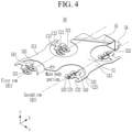
- FIG. 4 is a perspective view of the tab member disclosed in FIGS. 1 to 3
- FIG. 5 is a perspective view showing a state in which the insulating tape is attached to a welding portion between the electrode terminal and the tab member in the rechargeable battery module of FIG. 1 .
- the second extension tab 542 may horizontally extend from the second auxiliary portion 512 of the main body portion 51, and the second neck 532 may be provided in pairs, may be bent downward from the second extension tab 542, and may be disposed on a side surface inside the opening 224 through the opening 224 of the top holder 22.
- a pair of second tabs 522 may be connected to a pair of second necks 532 to avoid two battery cells 10 disposed in the direction of the second row R2 and to be connected to the positive electrode terminals 41 of the two battery cells 10.
- the first tab 521, the first neck 531, the first extension tab 541, and the first auxiliary portion 511 of the first row R1 may make current paths of two battery cells 10 disposed in the first row R1 to the main body portion 51 the same. For example, a voltage difference between the battery cells 10 of the first row R1 may be minimized (e.g., equal to zero).
- the second tab 522, the second neck 532, the second extension tab 542, and the second auxiliary portion 512 of the second row R2 may make current paths of two battery cells 10 disposed in the second row R2 to the main body portion 51 the same. For example, a voltage difference between the battery cells 10 of the second row R2 may be minimized (e.g., equal to zero).
- the main body portion 51 may be connected to the first auxiliary portion 511 and the second auxiliary portion 512 to connect two battery cells 10 connected in parallel in the first row R1 and two battery cells 10 connected in parallel in the second row R2 in series.
- a current of the two battery cells 10 connected in parallel in the first row R1 may flow to the main body portion 51, and a current of the two battery cells 10 connected in parallel in the second row R2 may flow to the main body portion 51.
- a voltage difference between the battery cells 10 of the first row R1 and the second row R2 may be minimized (e.g., equal to zero). As a result, it is possible to prevent the lifespan of the battery cells 10 from being shortened.
- the first and second extension tabs 541 and 542 and the opening 224 may form an outlet OL at upper portions of the negative and positive electrode terminals 42 and 41.
- the outlet OL may be set (or disposed) between the tab member 50 and the top holder 22 if there is a step difference between the top holder 22 and the battery cell 10 and the tab member 50 is bent.
- the outlet OL may dissipate heat generated inside the rechargeable battery module in advance to prevent thermal runaway of the rechargeable battery module so that safety against the thermal runaway is improved.
- the insulating tape 60 may include a main body attachment portion 61 attached to the main body portion 51, an extension attachment portion 621 attached to the first and second extension tabs 541 and 542 of the extension portion, and a tab attachment portion 622 attached to the first and second tabs 521 and 522 of the tab portion.
- the tab attachment portion 622 may be separated by a cutting line CL with respect to the main body attachment portion 61 and the extension attachment portion 621 which are integrally formed.
- the main body attachment portion 61 and the extension attachment portion 621 may be attached to the main body portion 51 and the first and second extension tabs 541 and 542 that are the extension portions, and the tab attachment portion 622 may be attached to the first and second tabs 521 and 522 of the tab portion and the negative and positive electrode terminals 42 and 41.
- the main body attachment portion 61 and the extension attachment portion 621 that are integrally formed in the insulating tape 60 may be connected to the tab attachment portion 622, and may be separated from each other during an attachment process.
- the insulating tape 60 may further include a connection portion 63. Because the connection portion 63 is separated in the attachment process, the main body attachment portion 61 and the extension attachment portion 621 may be attached to the main body portion 51 and the first and second extension tabs 541 and 542, and the tab attachment portion 622 may be attached to the first and second tabs 521 and 522.
- the extension attachment portion 621, the main body attachment portion 61, and the tab attachment portion 622 may be integrally formed and may include a T-shaped boundary line L1 and a curved line boundary line L2.
- the T-shaped boundary line L1 may be formed along a boundary between the extension attachment portion 621 and the tab attachment portion 622.
- the curved line boundary line L2 may be formed along a boundary between the main body attachment portion 61 and the tab attachment portion 622.
- a pair of second necks 532 may be disposed in a straight line at the neck portion, and the first extension tab 541 may be formed in a T-shape at the extension portion so that the T-shaped boundary line L1 is set to correspond to the pair of second necks 532 and the first extension tab 541.
- the curved boundary line L2 may be formed along the circular opening 224 of the top holder 22 to be connected to the T-shaped boundary line L1.
- connection portion 63 may be formed at the curved line boundary line L2 to connect the main body attachment portion 61 and the tab attachment portion 622. If the insulating tape 60 is attached to the tab member 50, they may be separated from each other. The remaining portion of the curved line boundary line L2 that does not include the connection portion 63 and the T-shaped boundary line L1 may be connected to each other to complete the cutting line CL.
- Connection portions 63 may be provided at both ends of a diameter direction of the opening 224 of the holder at positions parallel to the T-shaped boundary line L1. If the main body attachment portion 61 is attached to the main body portion 51, the tab attachment portion 622 may be separated from the main body attachment portion 61 in a balanced state. For example, a separation time difference between the connection portions 63 of both ends may be minimized so that the tab attachment portion 622 is accurately attached to a welding portion between the second tab 522 and the positive electrode terminal 41.
- the top holder 22 and the positive electrode terminal 41 may have a step difference between each other, and the second neck 532 may have a length corresponding to the step difference.
- the second neck 532 may be bent at the second auxiliary portion 512 of the main body portion 51 and the second extension tab 542, and the second tab 522 may be bent at the second neck 532.
- the welding portion between the second tab 522 and the positive electrode terminal 41 may be insulated by the tab attachment portion 622. It is possible to prevent corrosion (for example, galvanic corrosion) of the welding portion between the second tab 522 and the positive electrode terminal 41.
- a space between the tab attachment portion 622 of the insulating tape 60 and the second tab 522 may be removed.
- the tab attachment portion 622 may be separated from the main body attachment portion 61 to be attached to the second tab 522 in a process of attaching the main body attachment portion 61 to the main body portion 51.
- workability may be improved.
- the first and second extension tabs 541 and 542 and the opening 224 may form the outlet OL at an upper portion of the positive electrode terminal 41.
- the outlet OL may be set (or disposed) between the tab member 50 and the top holder 22 if there is a step difference between the top holder 22 and the battery cell 10 and the tab member 50 is bent.
- the outlet OL may dissipate heat generated inside the rechargeable battery module in advance to prevent thermal runaway of the rechargeable battery module so that safety against the thermal runaway is improved.
- FIG. 8 is a cross-sectional perspective view taken along a line VIII-VIII in a state in which the rechargeable battery module of FIG. 1 is included within a case
- FIG. 9 is a cross-sectional perspective view taken along a line IX-IX in a state in which the rechargeable battery module of FIG. 1 is included within the case.
- the rechargeable battery module may further include the case 70 that accommodates the holder 20.
- the case 70 may be connected to the outlet OL, and may include a through hole TH at at least one side to dissipate heat.
- the holder 20 may further include a corresponding hole RH at a portion corresponding to the through hole TH of the case 70.
- the heat may be discharged to the outside through the outlet OL of the holder 20 and the through hole TH of the case 70, and may be discharged to the through hole TH through the corresponding hole RH. As a result, thermal runaway of the rechargeable battery module may be prevented.
- a method of manufacturing a rechargeable battery module may comprise providing a holder that accommodates a plurality of battery cells; installing a tab member installed in holder, the tab member to be welded to electrode terminals of the plurality of battery cells; and installing an insulating tape that insulates the tab member in the holder, wherein the tab member comprises: a main body portion disposed on the holder; an extension portion having a width and extending along at least a portion of the main body portion; a neck portion bent downward from the extension portion to be disposed inside an opening of the holder; and a tab portion bent from the neck portion to be connected to a respective one of the electrode terminals of the plurality of battery cells, and wherein the extension portion and the opening form an outlet at an upper portion of the respective one of the electrode terminals.
- the insulating tape may comprise a main body attachment portion attached to the main body portion; an extension attachment portion connected to the main body attachment portion to be attached to the extension portion; and a tab attachment portion separated by a cutting line with respect to the main body attachment portion and the extension attachment portion, the tab attachment portion to be attached to the tab portion and the respective one of the electrode terminals.
- the method may further comprise attaching the main body attachment portion to the main body portion; attaching the extension attachment portion to the extension portion; and attaching the tab attachment portion to the tab portion and the respective one of the electrode terminals.
- the insulating tape may further comprise a connection portion.
- the method may further comprise connecting the main body attachment portion and the extension attachment portion to the tab attachment portion with the connection portion and separating the main body attachment portion and the extension attachment portion from the tab attachment portion with the connection portion.
- Each of the plurality of battery cells may comprise cylindrical rechargeable batteries, and the holder may comprise a plurality of circular openings corresponding to both ends along an axial direction of the plurality of battery cells.
- the method may further comprise forming the plurality of circular openings in the holder.
- the extension portion may comprise first and second branches disposed on respective sides of a slit opening formed in an extension direction
- the neck portion may comprise a first neck portion connected to the first branch of the extension portion and a second neck portion connected to the second branch of the extension portion
- the tab portion may comprise a first tab portion connected to the first neck portion and a second tab portion connected to the second neck portion.
- the method may further comprise forming the tab member at least in part by: forming the first and second branches of the extension portion on respective sides of the slit opening formed in the extension direction; forming the first neck portion connected to the first branch of the extension portion and the second neck portion connected to the second branch of the extension portion; and forming the first tab portion connected to the first neck portion and the second tab portion connected to the second neck portion.
- the method may further comprise providing a case accommodating the holder and connecting the case to the outlet, wherein the case includes a through hole on at least one side of the case to dissipate heat from an interior of the case.
- the method may further comprise arranging the plurality of battery cells in the holder.
Landscapes
- Chemical & Material Sciences (AREA)
- Chemical Kinetics & Catalysis (AREA)
- Electrochemistry (AREA)
- General Chemical & Material Sciences (AREA)
- Connection Of Batteries Or Terminals (AREA)
- Battery Mounting, Suspending (AREA)
- Secondary Cells (AREA)
Abstract
A battery module includes: a plurality of battery cells; a holder that accommodates the plurality of battery cells; a tab member installed at the holder to be welded to electrode terminals of the plurality of battery cells; and an insulating tape that insulates the tab member. The tab member includes a main body portion disposed on the holder, an extension portion having a width and extending along at least a portion of the main body portion, a neck portion bent downward from the extension portion to be disposed inside an opening of the holder, and a tab portion bent from the neck portion to be connected to a respective one of the electrode terminals of the plurality of battery cells, and the extension portion and the opening form an outlet at an upper portion of the respective one of the electrode terminals.
Description
- The present disclosure relates to a battery module, and more specifically, to a battery module connecting battery cells with a tab member.
- A rechargeable battery is a battery that is capable of being repeatedly charged and discharged, unlike a primary battery. Small-capacity rechargeable batteries may be used in portable small electronic devices such as mobile phones, laptop computers, or camcorders. Large-capacity and high-density rechargeable batteries may be used as a power source for driving a motor of a hybrid vehicle or an electric vehicle or an energy storage device of the hybrid vehicle or the electric vehicle.
- Embodiments of the present disclosure provide a battery module that forms an outlet between a tab member and a holder when there is a step difference between the holder and a battery cell and the tab member is bent.
- Embodiments of the present disclosure provide a battery module that forms an outlet between a tab member and a holder when there is a step difference between the holder and a battery cell, the tab member is bent, and an insulating tape is attached to the tab member to insulate the tab member.
- Embodiments of the present disclosure provide a battery module including a hole in a holder.
- A battery module according to embodiments of the present disclosure includes: a plurality of battery cells; a holder that accommodates the plurality of battery cells; a tab member installed at the holder to be welded to electrode terminals of the plurality of battery cells; and an insulating tape that insulates the tab member. The tab member comprises a main body portion disposed on the holder, an extension portion having a width and extending along at least a portion of the main body portion, a neck portion bent downward from the extension portion to be disposed inside an opening of the holder, and a tab portion bent from the neck portion to be connected to a respective one of the electrode terminals of the plurality of battery cells, and wherein the extension portion and the opening form an outlet at an upper portion of the respective one of the electrode terminals.
- The insulating tape may include: a main body attachment portion attached to the main body portion; an extension attachment portion connected to the main body attachment portion to be attached to the extension portion; and a tab attachment portion separated by a cutting line with respect to the main body attachment portion and the extension attachment portion to be attached to the tab portion and the respective one of the electrode terminals.
- The insulating tape may further include a connection portion connecting the main body attachment portion and the extension attachment portion to the tab attachment portion and separating the main body attachment portion and the extension attachment portion from the tab attachment portion in an attachment process.
- Each of the plurality of battery cells may be cylindrical batteries, and the holder may comprise a plurality of circular openings corresponding to both ends along an axial direction of the plurality of battery cells.
- The extension portion may comprise first and second branches disposed on respective sides of a slit opening formed in an extension direction, the neck portion may comprise a first neck portion connected to the first branch of the extension portion and a second neck portion connected to the second branch of the extension portion, and the tab portion may comprise a first tab portion connected to the first neck portion and a second tab portion connected to the second neck portion.
- The battery module may further include a case accommodating the holder. The case may be connected to the outlet and may include a through hole on at least one side of the case to dissipate heat from an interior of the case.
- The battery module may further comprise a second tab member.
- In some embodiments, there is provided a method of manufacturing a battery module. The method may comprise providing a holder that accommodates a plurality of battery cells; installing a tab member installed in holder, the tab member to be welded to electrode terminals of the plurality of battery cells; and installing an insulating tape that insulates the tab member in the holder, wherein the tab member comprises: a main body portion disposed on the holder; an extension portion having a width and extending along at least a portion of the main body portion; a neck portion bent downward from the extension portion to be disposed inside an opening of the holder; and a tab portion bent from the neck portion to be connected to a respective one of the electrode terminals of the plurality of battery cells, and wherein the extension portion and the opening form an outlet at an upper portion of the respective one of the electrode terminals.
- The insulating tape may comprise a main body attachment portion attached to the main body portion; an extension attachment portion connected to the main body attachment portion to be attached to the extension portion; and a tab attachment portion separated by a cutting line with respect to the main body attachment portion and the extension attachment portion, the tab attachment portion to be attached to the tab portion and the respective one of the electrode terminals. The method may further comprise attaching the main body attachment portion to the main body portion; attaching the extension attachment portion to the extension portion; and attaching the tab attachment portion to the tab portion and the respective one of the electrode terminals.
- The insulating tape may further comprise a connection portion. The method may further comprise connecting the main body attachment portion and the extension attachment portion to the tab attachment portion with the connection portion and separating the main body attachment portion and the extension attachment portion from the tab attachment portion with the connection portion.
- Each of the plurality of battery cells may comprise cylindrical batteries, and the holder may comprise a plurality of circular openings corresponding to both ends along an axial direction of the plurality of battery cells.
- The method may further comprise forming the plurality of circular openings in the holder.
- The extension portion may comprise first and second branches disposed on respective sides of a slit opening formed in an extension direction, the neck portion may comprise a first neck portion connected to the first branch of the extension portion and a second neck portion connected to the second branch of the extension portion, and the tab portion may comprise a first tab portion connected to the first neck portion and a second tab portion connected to the second neck portion.
- The method may further comprise forming the tab member at least in part by: forming the first and second branches of the extension portion on respective sides of the slit opening formed in the extension direction; forming the first neck portion connected to the first branch of the extension portion and the second neck portion connected to the second branch of the extension portion; and forming the first tab portion connected to the first neck portion and the second tab portion connected to the second neck portion.
- The method may further comprise providing a case accommodating the holder and connecting the case to the outlet, wherein the case includes a through hole on at least one side of the case to dissipate heat from an interior of the case.
- The method may further comprise arranging the plurality of battery cells in the holder.
- In some embodiments there is provided a battery module comprising: a holder that accommodates a plurality of battery cells; a tab member installed at the holder to be welded to electrode terminals of the plurality of battery cells; and an insulating tape that insulates the tab member. The tab member may comprise a main body portion disposed on the holder; an extension portion having a width and extending along at least a portion of the main body portion; a neck portion bent downward from the extension portion to be disposed inside an opening of the holder; and a tab portion bent from the neck portion to be connected to a respective one of the electrode terminals of the plurality of battery cells, and wherein the extension portion and the opening form an outlet at an upper portion of the respective one of the electrode terminals.
- The insulating tape may comprise a main body attachment portion attached to the main body portion; an extension attachment portion connected to the main body attachment portion to be attached to the extension portion; and a tab attachment portion separated by a cutting line with respect to the main body attachment portion and the extension attachment portion, the tab attachment portion to be attached to the tab portion and the respective one of the electrode terminals.
- The insulating tape may further comprise a connection portion connecting the main body attachment portion and the extension attachment portion to the tab attachment portion and separating the main body attachment portion and the extension attachment portion from the tab attachment portion in an attachment process.
- The extension portion may comprise first and second branches disposed on respective sides of a slit opening formed in an extension direction, the neck portion may comprise a first neck portion connected to the first branch of the extension portion and a second neck portion connected to the second branch of the extension portion, and the tab portion may comprise a first tab portion connected to the first neck portion and a second tab portion connected to the second neck portion.
- The battery module of the embodiments may improve safety against thermal runaway by dissipating a heat in advance through an outlet formed between a tab member and a holder. The battery module of the embodiments may include a hole in a case to dissipate a heat so that it further improves the safety against thermal runaway.
- The battery module of the embodiments may include an insulating tape including an extension attachment portion connected to a body attachment portion and a tab attachment portion separated from the extension attachment portion to be attached to a tab portion and an electrode terminal, so that it prevents corrosion of the tab portion and the electrode terminal welded and stably maintains an open state of an outlet (or a discharge port) not to interfere with prevention of the thermal runaway.
-
-
FIG. 1 is a perspective view of a rechargeable battery module according to some embodiments of the present disclosure. -
FIG. 2 is an exploded perspective view showing a state in which an insulating tape is separated from the rechargeable battery module ofFIG. 1 . -
FIG. 3 is an exploded perspective view showing a state in which a tab member is separated from the rechargeable battery module ofFIG. 2 . -
FIG. 4 is a perspective view of the tab member disclosed inFIGS. 1 to 3 . -
FIG. 5 is a perspective view showing a state in which the insulating tape is attached to a welding portion between an electrode terminal and the tab member in the rechargeable battery module ofFIG. 1 . -
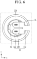
FIG. 6 is a plan view showing a state before the insulating tape is attached to the tab member ofFIG. 5 . -
FIG. 7 is a plan view showing a state in which the insulating tape is attached to the tab member ofFIG. 6 . -
FIG. 8 is a cross-sectional perspective view taken along a line VIII-VIII in a state in which the rechargeable battery module ofFIG. 1 is included within a case. -
FIG. 9 is a cross-sectional perspective view taken along a line IX-IX in a state in which the rechargeable battery module ofFIG. 1 is included within the case. - The present disclosure will be described more fully hereinafter with reference to the accompanying drawings, in which embodiments of the disclosure are shown. As those skilled in the art would realize, the described embodiments may be modified in various different ways, all without departing from the scope of the present disclosure. The drawings and description are to be regarded as illustrative in nature and not restrictive. Like reference numerals designate like elements throughout the specification.
- A rechargeable battery may be used in a rechargeable battery module including a plurality of battery cells connected in series and/or in parallel to drive the motor of a hybrid vehicle which may require relatively high energy density. For example, a rechargeable battery module may be formed by connecting electrode terminals of the plurality of battery cells. The number of battery cells provided may correspond to a desired amount of electric power to implement a relatively high output rechargeable battery module (e.g. the rechargeable battery module of an electric vehicle).
- For example, the rechargeable battery module may be formed by accommodating the plurality of battery cells in a holder and connecting the plurality of battery cells in series and/or in parallel through a tab. The rechargeable battery module may include tabs that connect the battery cells and a battery management system connected to the tabs as a voltage and a current may be high depending on a usage condition of a consumer.
- In this case, an insulating tape may be used to insulate the tabs. Because the insulating tape may be integrally formed, there may be a step difference between the holder and the battery cell. Thus, if the tab is bent, the insulating tape is attached to upper sides of the holder and the tab, so that the insulating tape may not directly insulate a welding portion between the electrode terminal and the tab. In other words, the welding portion between the electrode terminal and the tab forms a space separated from the insulating tape, and this portion exposed to the empty space may be vulnerable to galvanic corrosion.
- Additionally, because the insulating tape closes the space between the holder and the tab member, it may be difficult to dissipate heat so risk of thermal runaway may be high. Also, a heat generated internally stays within a case that may accommodate the rechargeable battery module, so that the risk of thermal runaway may be high.
-
FIG. 1 is a perspective view of a rechargeable battery module according to some embodiments of the present disclosure,FIG. 2 is an exploded perspective view showing a state in which an insulating tape is separated from the rechargeable battery module ofFIG. 1 , andFIG. 3 is an exploded perspective view showing a state in which a tab member is separated from the rechargeable battery module ofFIG. 2 . - Referring to
FIGS. 1 to 3 , therechargeable battery module 1 of the embodiments may include a plurality ofbattery cells 10, aholder 20 that may accommodate thebattery cells 10, atab member 50 welded to electrodeterminals 40 of thebattery cells 10, and the insulatingtape 60 that electrically insulates thetab member 50. - Each of the plurality of
battery cells 10 may be a cylindrical rechargeable battery, and may includeelectrode terminals 40 at both ends of an axial direction of the cylindrical rechargeable battery. For example, theelectrode terminal 40 may include apositive electrode terminal 41 and anegative electrode terminal 42 provided at both ends along an axial direction of eachbattery cell 10. - The
holder 20 may include abottom holder 21 and atop holder 22. Thebottom holder 21 and thetop holder 22 may form a honeycomb structure therein to accommodate the plurality ofbattery cells 10 spaced apart in a first direction (an x-axis direction) and a second direction (a y-axis direction) crossing the first direction, so that thetop holder 22 and thebottom holder 21 are coupled to each other in a third direction (a z-axis direction) crossing the second direction and are firmly fastened by afastening member 23. - In the states shown
FIGS. 1 to 3 , thebottom holder 21 may accommodate lower sides of thebattery cells 10, and thetop holder 22 may accommodate upper sides of thebattery cells 10. In the states shown inFIGS. 1 to 3 , thebottom holder 21 and thetop holder 22 may be fastened with thefastening member 23. - For example, the
bottom holder 21 and thetop holder 22 may be further coupled with a snap-fit structure having acoupling portion 24 provided outside thebottom holder 21 and a protrudingportion 25 provided outside thetop holder 22 corresponding to thecoupling portion 24. - The plurality of
battery cells 10 may be accommodated in theholder 20 arranged in a first row R1 and a second row R2 parallel to the first row R1. The first row R1 and the second row R2 may be set along the second direction and may be spaced apart from each other in the first direction. The rechargeable battery module may comprise multiple of the first and second rows R1, R2. - As an example, the
negative electrode terminal 42 may be disposed at an upper portion of the first row R1, and thepositive electrode terminal 41 may be disposed at a lower portion of the first row R1. In some embodiments, thepositive electrode terminal 41 may be disposed at an upper portion of the second row R2, and thenegative electrode terminal 42 may be disposed at a lower portion of the second row R2. - A center of an axial direction of each of the
battery cells 10 disposed in the first row R1 and a center of an axial direction of each of thebattery cells 10 disposed in the second row R2 may be disposed offset from each other in a direction along the first and second rows R1, R2 (e.g., in the second direction along a y-axis). For example, intervals between thebattery cells 10 adjacent to each other may be the same. - For example, the
battery cells 10 disposed in the second row R2 may be shifted in the second direction (the y-axis direction) with respect to thebattery cells 10 disposed in the first row R1. In some embodiments, side surfaces of the twobattery cells 10 disposed at ends of the first row R1 and the second row R2 may be disposed to be misaligned from disposition directions of the first row R1 and the second row R2. As such, a line passing through axial centers of the twobattery cells 10 disposed at ends of the first row R1 and the second row R2 may form an angle with a line along the second row that is other than 90 degrees. -
Tab members 50 may be disposed inseating grooves 221 of thebottom holder 21 and thetop holder 22 to connect theelectrode terminals 40 corresponding to thetab members 50. A protrudingportion 222 may be provided at one side of theseating groove 221 to be coupled to a coupling hole H corresponding to thetab member 50. - For example, the
seating groove 221 may set a position of thetab member 50 before thetab member 50 is welded to theelectrode terminal 40 to keep the position of thetab member 50 constant. In some embodiments, the protrudingportion 222 may be coupled to the coupling hole H when setting of the position of thetab member 50 is completed to prevent thetab member 50 from being separated from theseating groove 221. - As an example, the
tab members 50 may comprise nickel, and may electrically connect thebattery cells 10 in parallel and/or in series to electrically connect thebattery cells 10 to a battery management system (BMS) 30 ofFIG. 8 . Thetab members 50 may be formed by punching and bending a thin plate. - As an example, the battery management system (BMS) 30 may be installed on side surfaces of the
bottom holder 21 and thetop holder 22. Each of thetab members 50 may have an output terminal (or an output end) 54 at one side of the first direction (the x-axis direction), so that the respective tab member is electrically connected to the battery management system (BMS) 30 through theoutput terminal 54. For installation of thetab members 50, side surfaces of thebottom holder 21 and thetop holder 22 may be opened as appropriate. -
FIG. 4 is a perspective view of the tab member disclosed inFIGS. 1 to 3 , andFIG. 5 is a perspective view showing a state in which the insulating tape is attached to a welding portion between the electrode terminal and the tab member in the rechargeable battery module ofFIG. 1 . - Referring to
FIG. 4 andFIG. 5 , thetab member 50 may include amain body portion 51, afirst extension tab 541 and asecond extension tab 542 that are extension portions of thetab member 50, afirst tab 521 and asecond tab 522 that are tab portions of thetab member 50, and afirst neck 531 and asecond neck 532 that are neck portions of thetab member 50. - The
top holder 22 may accommodate thebattery cells 10, and may includecircular openings 224 that are open and correspond to both ends of the axial direction of thebattery cell 10. Theopening 224 may be formed in a structure corresponding to thebottom holder 21. For simplicity of explanation, a description of thebottom holder 21 is omitted. - A connection structure of the
first tab 521 may include an 11th connection C11 that is bent to be welded to thenegative electrode terminal 42 in two branches that extend in a height direction (the z-axis direction) through thefirst neck 531, a 12th connection C12 extending in a direction perpendicular to the first row R1 through thefirst extension tab 541, and a 13th connection C13 extending in a direction of the first row R1 through a firstauxiliary portion 511 to be connected to themain body portion 51. - A connection structure of the
second tab 522 may include a 21st connection C21 that is bent to be welded to thepositive electrode terminal 41 in two branches that extend in the height direction (the z-axis direction) through thesecond neck 532, a 22nd connection C22 extending in a direction perpendicular to the second row R2 through thesecond extension tab 542, and a 23rd connection C23 extending in a direction of the second row R2 through a secondauxiliary portion 512 to be connected to themain body portion 51. - The connection structure of the
first tab 521 including the 11th connection C11, the 12th connection C12, and the 13th connection C13 and the connection structure of thesecond tab 522 including the 21st connection C21, the 22nd connection C22, and the 23rd connection C23 allow the negative andpositive electrode terminals main body portion 51 over a long distance. - For example, a difference between a total distance of the connection structure of the
first tab 521 to a final output terminal of thetab member 50 through themain body portion 51 and a total distance of the connection structure of thesecond tab 522 to the final output terminal of thetab member 50 through themain body portion 51 may be minimized. In some embodiments, a voltage difference between thebattery cell 10 in the first row R1 and thebattery cell 10 in the second row R2 may be minimized (e.g., equal to zero). - Referring back to
FIGS. 1 to 5 , themain body portion 51 may be disposed between the first row R1 and the second row R2 of thebattery cells 10 to be connected in the second direction (the y-axis direction). For example, themain body portion 51 extending in the second direction (the y-axis direction) may include the firstauxiliary portion 511 and the secondauxiliary portion 512 connected in the first direction (the x-axis direction). - The
first tab 521 may be connected tonegative electrode terminals 42 of the first row R1. For example, thefirst tab 521 may be connected to themain body portion 51 through thefirst neck 531, thefirst extension tab 541, and the firstauxiliary portion 511, and may be disposed in the first row R1. Thesecond tab 522 may be connected topositive electrode terminals 41 of the second row R2. For example, thesecond tab 522 may be connected to themain body portion 51 through thesecond neck 532, thesecond extension tab 542, and the secondauxiliary portion 512, and may be disposed in the second row R2. - The first
auxiliary portion 511 may include a pair offirst tabs 521 that are electrically connected to connect thenegative electrode terminals 42 of twobattery cells 10 disposed in the second direction (y-axis direction) in parallel. The firstauxiliary portion 511 may avoid (e.g., be disposed around) twobattery cells 10 disposed in the direction of the first row R1 to be connected to themain body portion 51 through a space between the twobattery cells 10. - The
first extension tab 541 may horizontally extend from the firstauxiliary portion 511 of themain body portion 51, and may be formed in two branches at both sides of a slit opening formed in the extension direction. Thesecond extension tab 542 may horizontally extend from the secondauxiliary portion 512 of themain body portion 51, and may be formed in two branches at both sides of a slit opening formed in the extension direction. - The
first necks 531 may be provided in pairs, may be bent downward from thefirst extension tab 541, and may be disposed on a side surface inside theopening 224 through theopening 224 of thetop holder 22. A pair offirst tabs 521 may be connected to a pair offirst necks 531 to avoid the twobattery cells 10 disposed in the direction of the first row R1 and to be connected to thenegative electrode terminals 42 of the twobattery cells 10. - The second
auxiliary portion 512 may include a pair ofsecond tabs 522 that are electrically connected to connect thepositive electrode terminals 41 of twobattery cells 10 disposed in the second direction (the y-axis direction) in parallel. The secondauxiliary portion 512 may avoid (e.g., be disposed around) twobattery cells 10 disposed in the second row R2 direction to be connected to themain body portion 51 through a space between the twobattery cells 10. - The
second extension tab 542 may horizontally extend from the secondauxiliary portion 512 of themain body portion 51, and thesecond neck 532 may be provided in pairs, may be bent downward from thesecond extension tab 542, and may be disposed on a side surface inside theopening 224 through theopening 224 of thetop holder 22. A pair ofsecond tabs 522 may be connected to a pair ofsecond necks 532 to avoid twobattery cells 10 disposed in the direction of the second row R2 and to be connected to thepositive electrode terminals 41 of the twobattery cells 10. - The
first tab 521, thefirst neck 531, thefirst extension tab 541, and the firstauxiliary portion 511 of the first row R1 may make current paths of twobattery cells 10 disposed in the first row R1 to themain body portion 51 the same. For example, a voltage difference between thebattery cells 10 of the first row R1 may be minimized (e.g., equal to zero). - The
second tab 522, thesecond neck 532, thesecond extension tab 542, and the secondauxiliary portion 512 of the second row R2 may make current paths of twobattery cells 10 disposed in the second row R2 to themain body portion 51 the same. For example, a voltage difference between thebattery cells 10 of the second row R2 may be minimized (e.g., equal to zero). - In some embodiments, the
main body portion 51 may be connected to the firstauxiliary portion 511 and the secondauxiliary portion 512 to connect twobattery cells 10 connected in parallel in the first row R1 and twobattery cells 10 connected in parallel in the second row R2 in series. - For example, a current of the two
battery cells 10 connected in parallel in the first row R1 may flow to themain body portion 51, and a current of the twobattery cells 10 connected in parallel in the second row R2 may flow to themain body portion 51. - In some embodiments, because the first row R1 and the second row R2 share the
main body portion 51 of thetab member 50, a voltage difference between thebattery cells 10 of the first row R1 and the second row R2 may be minimized (e.g., equal to zero). As a result, it is possible to prevent the lifespan of thebattery cells 10 from being shortened. - Referring to
FIG. 5 andFIG. 6 , the first andsecond extension tabs opening 224 may form an outlet OL at upper portions of the negative andpositive electrode terminals tab member 50 and thetop holder 22 if there is a step difference between thetop holder 22 and thebattery cell 10 and thetab member 50 is bent. The outlet OL may dissipate heat generated inside the rechargeable battery module in advance to prevent thermal runaway of the rechargeable battery module so that safety against the thermal runaway is improved. - Referring back to
FIGS. 1 to 3 andFIGS. 5 and7 , the insulatingtape 60 may include a mainbody attachment portion 61 attached to themain body portion 51, anextension attachment portion 621 attached to the first andsecond extension tabs tab attachment portion 622 attached to the first andsecond tabs - The
tab attachment portion 622 may be separated by a cutting line CL with respect to the mainbody attachment portion 61 and theextension attachment portion 621 which are integrally formed. The mainbody attachment portion 61 and theextension attachment portion 621 may be attached to themain body portion 51 and the first andsecond extension tabs tab attachment portion 622 may be attached to the first andsecond tabs positive electrode terminals - The main
body attachment portion 61 and theextension attachment portion 621 that are integrally formed in the insulatingtape 60 may be connected to thetab attachment portion 622, and may be separated from each other during an attachment process. To this end, the insulatingtape 60 may further include aconnection portion 63. Because theconnection portion 63 is separated in the attachment process, the mainbody attachment portion 61 and theextension attachment portion 621 may be attached to themain body portion 51 and the first andsecond extension tabs tab attachment portion 622 may be attached to the first andsecond tabs - For example, the
top holder 22 may include arib 223 protruding between thetab members 50 adjacent to each other in the first direction and extending in the second direction. In some embodiments, the insulatingtape 60 may include acutout portion 64 corresponding to therib 223. If the insulatingtape 60 is disposed above thetab members 50 before the insulatingtape 60 is attached to thetab members 50, thecutout portion 64 may be coupled to therib 223 so that it is possible to prevent a flow of the insulatingtape 60. - Referring back to
FIG. 7 , the insulatingtape 60 attached to thepositive electrode terminal 41 will be described. - The
extension attachment portion 621, the mainbody attachment portion 61, and thetab attachment portion 622 may be integrally formed and may include a T-shaped boundary line L1 and a curved line boundary line L2. The T-shaped boundary line L1 may be formed along a boundary between theextension attachment portion 621 and thetab attachment portion 622. The curved line boundary line L2 may be formed along a boundary between the mainbody attachment portion 61 and thetab attachment portion 622. - A pair of
second necks 532 may be disposed in a straight line at the neck portion, and thefirst extension tab 541 may be formed in a T-shape at the extension portion so that the T-shaped boundary line L1 is set to correspond to the pair ofsecond necks 532 and thefirst extension tab 541. The curved boundary line L2 may be formed along thecircular opening 224 of thetop holder 22 to be connected to the T-shaped boundary line L1. - The
connection portion 63 may be formed at the curved line boundary line L2 to connect the mainbody attachment portion 61 and thetab attachment portion 622. If the insulatingtape 60 is attached to thetab member 50, they may be separated from each other. The remaining portion of the curved line boundary line L2 that does not include theconnection portion 63 and the T-shaped boundary line L1 may be connected to each other to complete the cutting line CL. -
Connection portions 63 may be provided at both ends of a diameter direction of theopening 224 of the holder at positions parallel to the T-shaped boundary line L1. If the mainbody attachment portion 61 is attached to themain body portion 51, thetab attachment portion 622 may be separated from the mainbody attachment portion 61 in a balanced state. For example, a separation time difference between theconnection portions 63 of both ends may be minimized so that thetab attachment portion 622 is accurately attached to a welding portion between thesecond tab 522 and thepositive electrode terminal 41. - The
top holder 22 and thepositive electrode terminal 41 may have a step difference between each other, and thesecond neck 532 may have a length corresponding to the step difference. For example, in thetab member 50, thesecond neck 532 may be bent at the secondauxiliary portion 512 of themain body portion 51 and thesecond extension tab 542, and thesecond tab 522 may be bent at thesecond neck 532. - In some embodiments, the main
body attachment portion 61 and theextension attachment portion 621 of the insulatingtape 60 that are separated may be attached to themain body portion 51 and thesecond extension tab 542 of thetab member 50, and thetab attachment portion 622 may be separated from the mainbody attachment portion 61 through theconnection portion 63 to be attached to thesecond tab 522. - For example, the welding portion between the
second tab 522 and thepositive electrode terminal 41 may be insulated by thetab attachment portion 622. It is possible to prevent corrosion (for example, galvanic corrosion) of the welding portion between thesecond tab 522 and thepositive electrode terminal 41. - A space between the
tab attachment portion 622 of the insulatingtape 60 and thesecond tab 522 may be removed. For example, it is possible to reduce theinsulation tape 60 by forming electrical insulation for the welding portion with a minimum area of theinsulation tape 60. - For example, because the insulating
tape 60 includes theconnection portion 63 connecting the mainbody attachment portion 61 and thetab attachment portion 622, thetab attachment portion 622 may be separated from the mainbody attachment portion 61 to be attached to thesecond tab 522 in a process of attaching the mainbody attachment portion 61 to themain body portion 51. Thus, workability may be improved. - If the insulating
tape 60 is attached, the first andsecond extension tabs opening 224 may form the outlet OL at an upper portion of thepositive electrode terminal 41. For example, the outlet OL may be set (or disposed) between thetab member 50 and thetop holder 22 if there is a step difference between thetop holder 22 and thebattery cell 10 and thetab member 50 is bent. The outlet OL may dissipate heat generated inside the rechargeable battery module in advance to prevent thermal runaway of the rechargeable battery module so that safety against the thermal runaway is improved. -
FIG. 8 is a cross-sectional perspective view taken along a line VIII-VIII in a state in which the rechargeable battery module ofFIG. 1 is included within a case, andFIG. 9 is a cross-sectional perspective view taken along a line IX-IX in a state in which the rechargeable battery module ofFIG. 1 is included within the case. - Referring to
FIG. 8 andFIG. 9 , the rechargeable battery module may further include thecase 70 that accommodates theholder 20. Thecase 70 may be connected to the outlet OL, and may include a through hole TH at at least one side to dissipate heat. In some embodiments, theholder 20 may further include a corresponding hole RH at a portion corresponding to the through hole TH of thecase 70. - If heat is generated in one of the
battery cells 10, the heat may be discharged to the outside through the outlet OL of theholder 20 and the through hole TH of thecase 70, and may be discharged to the through hole TH through the corresponding hole RH. As a result, thermal runaway of the rechargeable battery module may be prevented. - In some embodiments, there is provided a method of manufacturing a rechargeable battery module. The method may comprise providing a holder that accommodates a plurality of battery cells; installing a tab member installed in holder, the tab member to be welded to electrode terminals of the plurality of battery cells; and installing an insulating tape that insulates the tab member in the holder, wherein the tab member comprises: a main body portion disposed on the holder; an extension portion having a width and extending along at least a portion of the main body portion; a neck portion bent downward from the extension portion to be disposed inside an opening of the holder; and a tab portion bent from the neck portion to be connected to a respective one of the electrode terminals of the plurality of battery cells, and wherein the extension portion and the opening form an outlet at an upper portion of the respective one of the electrode terminals.
- The insulating tape may comprise a main body attachment portion attached to the main body portion; an extension attachment portion connected to the main body attachment portion to be attached to the extension portion; and a tab attachment portion separated by a cutting line with respect to the main body attachment portion and the extension attachment portion, the tab attachment portion to be attached to the tab portion and the respective one of the electrode terminals. The method may further comprise attaching the main body attachment portion to the main body portion; attaching the extension attachment portion to the extension portion; and attaching the tab attachment portion to the tab portion and the respective one of the electrode terminals.
- The insulating tape may further comprise a connection portion. The method may further comprise connecting the main body attachment portion and the extension attachment portion to the tab attachment portion with the connection portion and separating the main body attachment portion and the extension attachment portion from the tab attachment portion with the connection portion.
- Each of the plurality of battery cells may comprise cylindrical rechargeable batteries, and the holder may comprise a plurality of circular openings corresponding to both ends along an axial direction of the plurality of battery cells.
- The method may further comprise forming the plurality of circular openings in the holder.
- The extension portion may comprise first and second branches disposed on respective sides of a slit opening formed in an extension direction, the neck portion may comprise a first neck portion connected to the first branch of the extension portion and a second neck portion connected to the second branch of the extension portion, and the tab portion may comprise a first tab portion connected to the first neck portion and a second tab portion connected to the second neck portion.
- The method may further comprise forming the tab member at least in part by: forming the first and second branches of the extension portion on respective sides of the slit opening formed in the extension direction; forming the first neck portion connected to the first branch of the extension portion and the second neck portion connected to the second branch of the extension portion; and forming the first tab portion connected to the first neck portion and the second tab portion connected to the second neck portion.
- The method may further comprise providing a case accommodating the holder and connecting the case to the outlet, wherein the case includes a through hole on at least one side of the case to dissipate heat from an interior of the case.
- The method may further comprise arranging the plurality of battery cells in the holder.
- While this disclosure has been described in connection with what is presently considered to be practical embodiments, it is to be understood that the disclosure is not limited to the disclosed embodiments, but, on the contrary, is intended to cover various modifications and equivalent arrangements included within the scope of the appended claims.
<Description of symbols> 1: rechargeable battery module 10: battery cell 20: holder 21: bottom holder 22: top holder 23: fastening member 24: coupling portion 25: protruding portion 30: battery management system (BMS) 40: electrode terminal 41: positive electrode terminal 42: negative electrode terminal 50: tab member 51: main body portion 54: output terminal 60: insulating tape 61: main body attachment portion 63: connection portion 64: cutout portion 70: case 221: seating groove 222: protruding portion 223: rib 224: opening 511: first auxiliary portion 512: second auxiliary portion 521: first tab 522: second tab 531: first neck 532: second neck 541: first extension tab 542: second extension tab 621: extension attachment portion 622: tab attachment portion C11: 11th connection C12: 12th connection C13: 13th connection C21: 21st connection C22: 22nd connection C23: 23rd connection CL: cutting line H: coupling hole L1: T-shaped boundary line L2: curved line boundary line OL: outlet R1: first row R2: second row RH: corresponding hole TH: through hole
Claims (15)
- A battery module (1), comprising:a plurality of battery cells (10);a holder (20) that accommodates the plurality of battery cells (10);a tab member (50) installed at the holder (20) to be welded to electrode terminals (40) of the plurality of battery cells (10); andan insulating tape (60) that insulates the tab member (50),wherein the tab member (50) comprises:a main body portion (51) disposed on the holder (20);an extension portion having a width and extending along at least a portion of the main body portion (51);a neck portion bent downward from the extension portion to be disposed inside an opening (224) of the holder (20); and atab portion bent from the neck portion to be connected to a respective one of the electrode terminals (40) of the plurality of battery cells (10), and wherein the extension portion and the opening (224) form an outlet at an upper portion of the respective one of the electrode terminals (40).
- The battery module (1) as claimed in claim 1, wherein the insulating tape (60) comprises:a main body attachment portion (61) attached to the main body portion (51);an extension attachment portion (621) connected to the main body attachment portion (61) to be attached to the extension portion; anda tab attachment portion (622) separated by a cutting line with respect to the main body attachment portion (61) and the extension attachment portion (621), the tab attachment portion (622) to be attached to the tab portion and the respective one of the electrode terminals (40).
- The battery module (1) as claimed in claim 2, wherein the insulating tape (60) further comprises a connection portion (63) connecting the main body attachment portion (61) and the extension attachment portion (621) to the tab attachment portion (622) and separating the main body attachment portion (61) and the extension attachment portion (621) from the tab attachment portion (622) in an attachment process.
- The battery module (1) as any one of claims 1 to 3 wherein each of the plurality of battery cells (10) comprise cylindrical batteries, and the holder (20) comprises a plurality of circular openings (224) corresponding to both ends along an axial direction of the plurality of battery cells (10).
- The battery module (1) as any one of claims 1 to 4, wherein the extension portion comprises first and second branches disposed on respective sides of a slit opening (224) formed in an extension direction, the neck portion comprises a first neck (531) portion connected to the first branch of the extension portion and a second neck (532) portion connected to the second branch of the extension portion, and the tab portion comprises a first tab (521) portion connected to the first neck (531) portion and a second tab (522) portion connected to the second neck (532) portion.
- The battery module (1) as any one of in claims 1 to 5, further comprising a case (70) accommodating the holder (20),
wherein the case (70) is connected to the outlet and includes a through hole on at least one side of the case (70) to dissipate heat from an interior of the case (70). - The battery module (1) as any one of claims 1 to 6, further comprising a second tab (522) member.
- A method of manufacturing a battery module (1), the method comprising:providing a holder (20) that accommodates a plurality of battery cells (10);installing a tab member (50) installed in holder (20), the tab member (50) to be welded to electrode terminals (40) of the plurality of battery cells (10); andinstalling an insulating tape (60) that insulates the tab member (50) in the holder (20),wherein the tab member (50) comprises:a main body portion (51) disposed on the holder (20);an extension portion having a width and extending along at least a portion of the main body portion (51);a neck portion bent downward from the extension portion to be disposed inside an opening (224) of the holder (20); and atab portion bent from the neck portion to be connected to a respective one of the electrode terminals (40) of the plurality of battery cells (10), and wherein the extension portion and the opening (224) form an outlet at an upper portion of the respective one of the electrode terminals (40).
- The method as claimed in claim 8, wherein the insulating tape (60) comprises:a main body attachment portion (61) attached to the main body portion (51);an extension attachment portion (621) connected to the main body attachment portion (61) to be attached to the extension portion; anda tab attachment portion (622) separated by a cutting line with respect to the main body attachment portion (61) and the extension attachment portion (621), the tab attachment portion (622) to be attached to the tab portion and the respective one of the electrode terminals (40); and the method further comprises:attaching the main body attachment portion (61) to the main body portion (51);attaching the extension attachment portion (621) to the extension portion; andattaching the tab attachment portion (622) to the tab portion and the respective one of the electrode terminals (40).
- The method as claimed in claim 9, wherein the insulating tape (60) further comprises a connection portion (63) and the method further comprises connecting the main body attachment portion (61) and the extension attachment portion (621) to the tab attachment portion (622) with the connection portion (63) and separating the main body attachment portion (61) and the extension attachment portion (621) from the tab attachment portion (622) with the connection portion (63).
- The method as any one of claims 8 to 10, wherein each of the plurality of battery cells (10) comprise cylindrical batteries, and the holder (20) comprises a plurality of circular openings (224) corresponding to both ends along an axial direction of the plurality of battery cells (10).
- The method as claimed any one of claims 8 to 11, further comprising forming the plurality of circular openings (224) in the holder (20).
- The method as any one of claims 8 to 12, wherein the extension portion comprises first and second branches disposed on respective sides of a slit opening (224) formed in an extension direction, the neck portion comprises a first neck (531) portion connected to the first branch of the extension portion and a second neck (532) portion connected to the second branch of the extension portion, and the tab portion comprises a first tab (521) portion connected to the first neck (531) portion and a second tab (522) portion connected to the second neck (532) portion.
- The method as claimed in claim 13, further comprising forming the tab member (50) at least in part by:forming the first and second branches of the extension portion on respective sides of the slit opening (224) formed in the extension direction;forming the first neck (531) portion connected to the first branch of the extension portion and the second neck (532) portion connected to the second branch of the extension portion;and forming the first tab (521) portion connected to the first neck (531) portion and the second tab (522) portion connected to the second neck (532) portion.
- The method as any one of claims 8 to 14, further comprising providing a case (70) accommodating the holder (20) and connecting the case (70) to the outlet, wherein the case (70) includes a through hole on at least one side of the case (70) to dissipate heat from an interior of the case (70).
Applications Claiming Priority (1)
| Application Number | Priority Date | Filing Date | Title |
|---|---|---|---|
| KR1020230117104A KR20250034759A (en) | 2023-09-04 | 2023-09-04 | Rechargeable battery module |
Publications (1)
| Publication Number | Publication Date |
|---|---|
| EP4517966A1 true EP4517966A1 (en) | 2025-03-05 |
Family
ID=92633914
Family Applications (1)
| Application Number | Title | Priority Date | Filing Date |
|---|---|---|---|
| EP24197870.9A Pending EP4517966A1 (en) | 2023-09-04 | 2024-09-02 | Battery module |
Country Status (5)
| Country | Link |
|---|---|
| US (1) | US20250079668A1 (en) |
| EP (1) | EP4517966A1 (en) |
| JP (1) | JP7847621B2 (en) |
| KR (1) | KR20250034759A (en) |
| CN (1) | CN119560733A (en) |
Citations (4)
| Publication number | Priority date | Publication date | Assignee | Title |
|---|---|---|---|---|
| US20140017531A1 (en) * | 2011-03-31 | 2014-01-16 | Yuji Uehara | Battery pack |
| US20220311103A1 (en) * | 2021-03-24 | 2022-09-29 | Cellink Corporation | Multilayered flexible battery interconnects and methods of fabricating thereof |
| US20220367993A1 (en) * | 2019-12-04 | 2022-11-17 | Lg Energy Solution, Ltd. | Battery module, battery pack and vehicle |
| US20230155241A1 (en) * | 2020-09-21 | 2023-05-18 | Lg Energy Solution, Ltd. | Battery module, battery pack, and vehicle including same |
Family Cites Families (3)
| Publication number | Priority date | Publication date | Assignee | Title |
|---|---|---|---|---|
| KR102326596B1 (en) | 2018-11-05 | 2021-11-12 | 주식회사 엘지에너지솔루션 | Battery Pack Having Mounting Structure |
| CN111129654B (en) | 2020-01-19 | 2020-11-27 | 王佳先 | Assembled battery module |
| JP7353533B2 (en) * | 2021-07-30 | 2023-09-29 | 寧徳時代新能源科技股▲分▼有限公司 | Batteries, power consuming devices, methods and equipment for manufacturing batteries |
-
2023
- 2023-09-04 KR KR1020230117104A patent/KR20250034759A/en active Pending
-
2024
- 2024-08-05 US US18/794,336 patent/US20250079668A1/en active Pending
- 2024-09-02 EP EP24197870.9A patent/EP4517966A1/en active Pending
- 2024-09-03 CN CN202411225135.8A patent/CN119560733A/en active Pending
- 2024-09-04 JP JP2024151956A patent/JP7847621B2/en active Active
Patent Citations (4)
| Publication number | Priority date | Publication date | Assignee | Title |
|---|---|---|---|---|
| US20140017531A1 (en) * | 2011-03-31 | 2014-01-16 | Yuji Uehara | Battery pack |
| US20220367993A1 (en) * | 2019-12-04 | 2022-11-17 | Lg Energy Solution, Ltd. | Battery module, battery pack and vehicle |
| US20230155241A1 (en) * | 2020-09-21 | 2023-05-18 | Lg Energy Solution, Ltd. | Battery module, battery pack, and vehicle including same |
| US20220311103A1 (en) * | 2021-03-24 | 2022-09-29 | Cellink Corporation | Multilayered flexible battery interconnects and methods of fabricating thereof |
Also Published As
| Publication number | Publication date |
|---|---|
| US20250079668A1 (en) | 2025-03-06 |
| CN119560733A (en) | 2025-03-04 |
| KR20250034759A (en) | 2025-03-11 |
| JP7847621B2 (en) | 2026-04-17 |
| JP2025036396A (en) | 2025-03-14 |
Similar Documents
| Publication | Publication Date | Title |
|---|---|---|
| KR102754816B1 (en) | Battery pack and vehicle comprising the battery pack | |
| CN109478611B (en) | Battery submodule carrier, battery submodule, battery system and car | |
| EP3346517B1 (en) | Battery system | |
| KR20220101581A (en) | Battery pack and vehicle comprising the battery pack | |
| KR20220128310A (en) | Busbar assembly, battery pack comprising the busbar assembly and vehicle comprising the battery pack | |
| EP3506383B1 (en) | Battery module | |
| US20240250368A1 (en) | Battery Module Comprising Module Housing | |
| EP3319146A1 (en) | Battery system | |
| US20180013113A1 (en) | Battery submodule carrier, battery submodule, battery system and vehicle | |
| KR20220101476A (en) | Battery pack and vehicle comprising the battery pack | |
| US12183952B2 (en) | Battery pack with enhanced structure for preventing short circuit and shock | |
| JP7761670B2 (en) | Busbar assembly, battery pack including same, and automobile | |
| EP4447218A1 (en) | Rechargeable battery module | |
| KR20230061982A (en) | Secondart Battery | |
| US20250079668A1 (en) | Rechargeable battery module | |
| EP3514004B1 (en) | Battery module and battery pack including same | |
| EP4535529A1 (en) | Battery module | |
| US20220336911A1 (en) | Battery pack including high voltage wire assembly and method for manufacturing the battery pack | |
| US20240347882A1 (en) | Rechargeable battery module | |
| EP4601105A1 (en) | Battery pack and vehicle including same | |
| KR20260037819A (en) | Battery module and battery pack including the same | |
| KR20260061682A (en) | Busbar and battery pack including the same | |
| CN118801032A (en) | Rechargeable battery module | |
| KR20260047683A (en) | Battery module easy to install in pack case, and battery pack including the same | |
| KR20250022427A (en) | Battery module and battery pack including the same |
Legal Events
| Date | Code | Title | Description |
|---|---|---|---|
| PUAI | Public reference made under article 153(3) epc to a published international application that has entered the european phase |
Free format text: ORIGINAL CODE: 0009012 |
|
| STAA | Information on the status of an ep patent application or granted ep patent |
Free format text: STATUS: REQUEST FOR EXAMINATION WAS MADE |
|
| 17P | Request for examination filed |
Effective date: 20240902 |
|
| AK | Designated contracting states |
Kind code of ref document: A1 Designated state(s): AL AT BE BG CH CY CZ DE DK EE ES FI FR GB GR HR HU IE IS IT LI LT LU LV MC ME MK MT NL NO PL PT RO RS SE SI SK SM TR |