EP4517964A1 - Battery module, assembly apparatus for battery module and assembly method of battery module - Google Patents
Battery module, assembly apparatus for battery module and assembly method of battery module Download PDFInfo
- Publication number
- EP4517964A1 EP4517964A1 EP24160557.5A EP24160557A EP4517964A1 EP 4517964 A1 EP4517964 A1 EP 4517964A1 EP 24160557 A EP24160557 A EP 24160557A EP 4517964 A1 EP4517964 A1 EP 4517964A1
- Authority
- EP
- European Patent Office
- Prior art keywords
- heat blocking
- blocking member
- battery module
- assembly
- battery
- Prior art date
- Legal status (The legal status is an assumption and is not a legal conclusion. Google has not performed a legal analysis and makes no representation as to the accuracy of the status listed.)
- Pending
Links
Images








Classifications
-
- H—ELECTRICITY
- H01—ELECTRIC ELEMENTS
- H01M—PROCESSES OR MEANS, e.g. BATTERIES, FOR THE DIRECT CONVERSION OF CHEMICAL ENERGY INTO ELECTRICAL ENERGY
- H01M10/00—Secondary cells; Manufacture thereof
- H01M10/60—Heating or cooling; Temperature control
- H01M10/65—Means for temperature control structurally associated with the cells
- H01M10/658—Means for temperature control structurally associated with the cells by thermal insulation or shielding
-
- H—ELECTRICITY
- H01—ELECTRIC ELEMENTS
- H01M—PROCESSES OR MEANS, e.g. BATTERIES, FOR THE DIRECT CONVERSION OF CHEMICAL ENERGY INTO ELECTRICAL ENERGY
- H01M50/00—Constructional details or processes of manufacture of the non-active parts of electrochemical cells other than fuel cells, e.g. hybrid cells
- H01M50/10—Primary casings; Jackets or wrappings
- H01M50/14—Primary casings; Jackets or wrappings for protecting against damage caused by external factors
- H01M50/143—Fireproof; Explosion-proof
-
- H—ELECTRICITY
- H01—ELECTRIC ELEMENTS
- H01M—PROCESSES OR MEANS, e.g. BATTERIES, FOR THE DIRECT CONVERSION OF CHEMICAL ENERGY INTO ELECTRICAL ENERGY
- H01M50/00—Constructional details or processes of manufacture of the non-active parts of electrochemical cells other than fuel cells, e.g. hybrid cells
- H01M50/20—Mountings; Secondary casings or frames; Racks, modules or packs; Suspension devices; Shock absorbers; Transport or carrying devices; Holders
- H01M50/204—Racks, modules or packs for multiple batteries or multiple cells
- H01M50/207—Racks, modules or packs for multiple batteries or multiple cells characterised by their shape
- H01M50/211—Racks, modules or packs for multiple batteries or multiple cells characterised by their shape adapted for pouch cells
-
- B—PERFORMING OPERATIONS; TRANSPORTING
- B65—CONVEYING; PACKING; STORING; HANDLING THIN OR FILAMENTARY MATERIAL
- B65G—TRANSPORT OR STORAGE DEVICES, e.g. CONVEYORS FOR LOADING OR TIPPING, SHOP CONVEYOR SYSTEMS OR PNEUMATIC TUBE CONVEYORS
- B65G47/00—Article or material-handling devices associated with conveyors; Methods employing such devices
- B65G47/22—Devices influencing the relative position or the attitude of articles during transit by conveyors
- B65G47/26—Devices influencing the relative position or the attitude of articles during transit by conveyors arranging the articles, e.g. varying spacing between individual articles
- B65G47/261—Accumulating articles
-
- G—PHYSICS
- G01—MEASURING; TESTING
- G01B—MEASURING LENGTH, THICKNESS OR SIMILAR LINEAR DIMENSIONS; MEASURING ANGLES; MEASURING AREAS; MEASURING IRREGULARITIES OF SURFACES OR CONTOURS
- G01B11/00—Measuring arrangements characterised by the use of optical techniques
- G01B11/02—Measuring arrangements characterised by the use of optical techniques for measuring length, width or thickness
- G01B11/026—Measuring arrangements characterised by the use of optical techniques for measuring length, width or thickness by measuring distance between sensor and object
-
- H—ELECTRICITY
- H01—ELECTRIC ELEMENTS
- H01M—PROCESSES OR MEANS, e.g. BATTERIES, FOR THE DIRECT CONVERSION OF CHEMICAL ENERGY INTO ELECTRICAL ENERGY
- H01M10/00—Secondary cells; Manufacture thereof
- H01M10/04—Construction or manufacture in general
- H01M10/0404—Machines for assembling batteries
-
- H—ELECTRICITY
- H01—ELECTRIC ELEMENTS
- H01M—PROCESSES OR MEANS, e.g. BATTERIES, FOR THE DIRECT CONVERSION OF CHEMICAL ENERGY INTO ELECTRICAL ENERGY
- H01M10/00—Secondary cells; Manufacture thereof
- H01M10/60—Heating or cooling; Temperature control
- H01M10/61—Types of temperature control
- H01M10/613—Cooling or keeping cold
-
- H—ELECTRICITY
- H01—ELECTRIC ELEMENTS
- H01M—PROCESSES OR MEANS, e.g. BATTERIES, FOR THE DIRECT CONVERSION OF CHEMICAL ENERGY INTO ELECTRICAL ENERGY
- H01M10/00—Secondary cells; Manufacture thereof
- H01M10/60—Heating or cooling; Temperature control
- H01M10/64—Heating or cooling; Temperature control characterised by the shape of the cells
- H01M10/647—Prismatic or flat cells, e.g. pouch cells
-
- H—ELECTRICITY
- H01—ELECTRIC ELEMENTS
- H01M—PROCESSES OR MEANS, e.g. BATTERIES, FOR THE DIRECT CONVERSION OF CHEMICAL ENERGY INTO ELECTRICAL ENERGY
- H01M50/00—Constructional details or processes of manufacture of the non-active parts of electrochemical cells other than fuel cells, e.g. hybrid cells
- H01M50/10—Primary casings; Jackets or wrappings
- H01M50/183—Sealing members
- H01M50/184—Sealing members characterised by their shape or structure
-
- H—ELECTRICITY
- H01—ELECTRIC ELEMENTS
- H01M—PROCESSES OR MEANS, e.g. BATTERIES, FOR THE DIRECT CONVERSION OF CHEMICAL ENERGY INTO ELECTRICAL ENERGY
- H01M50/00—Constructional details or processes of manufacture of the non-active parts of electrochemical cells other than fuel cells, e.g. hybrid cells
- H01M50/20—Mountings; Secondary casings or frames; Racks, modules or packs; Suspension devices; Shock absorbers; Transport or carrying devices; Holders
- H01M50/204—Racks, modules or packs for multiple batteries or multiple cells
- H01M50/207—Racks, modules or packs for multiple batteries or multiple cells characterised by their shape
- H01M50/209—Racks, modules or packs for multiple batteries or multiple cells characterised by their shape adapted for prismatic or rectangular cells
-
- H—ELECTRICITY
- H01—ELECTRIC ELEMENTS
- H01M—PROCESSES OR MEANS, e.g. BATTERIES, FOR THE DIRECT CONVERSION OF CHEMICAL ENERGY INTO ELECTRICAL ENERGY
- H01M50/00—Constructional details or processes of manufacture of the non-active parts of electrochemical cells other than fuel cells, e.g. hybrid cells
- H01M50/20—Mountings; Secondary casings or frames; Racks, modules or packs; Suspension devices; Shock absorbers; Transport or carrying devices; Holders
- H01M50/258—Modular batteries; Casings provided with means for assembling
-
- H—ELECTRICITY
- H01—ELECTRIC ELEMENTS
- H01M—PROCESSES OR MEANS, e.g. BATTERIES, FOR THE DIRECT CONVERSION OF CHEMICAL ENERGY INTO ELECTRICAL ENERGY
- H01M50/00—Constructional details or processes of manufacture of the non-active parts of electrochemical cells other than fuel cells, e.g. hybrid cells
- H01M50/20—Mountings; Secondary casings or frames; Racks, modules or packs; Suspension devices; Shock absorbers; Transport or carrying devices; Holders
- H01M50/262—Mountings; Secondary casings or frames; Racks, modules or packs; Suspension devices; Shock absorbers; Transport or carrying devices; Holders with fastening means, e.g. locks
- H01M50/264—Mountings; Secondary casings or frames; Racks, modules or packs; Suspension devices; Shock absorbers; Transport or carrying devices; Holders with fastening means, e.g. locks for cells or batteries, e.g. straps, tie rods or peripheral frames
-
- H—ELECTRICITY
- H01—ELECTRIC ELEMENTS
- H01M—PROCESSES OR MEANS, e.g. BATTERIES, FOR THE DIRECT CONVERSION OF CHEMICAL ENERGY INTO ELECTRICAL ENERGY
- H01M50/00—Constructional details or processes of manufacture of the non-active parts of electrochemical cells other than fuel cells, e.g. hybrid cells
- H01M50/20—Mountings; Secondary casings or frames; Racks, modules or packs; Suspension devices; Shock absorbers; Transport or carrying devices; Holders
- H01M50/289—Mountings; Secondary casings or frames; Racks, modules or packs; Suspension devices; Shock absorbers; Transport or carrying devices; Holders characterised by spacing elements or positioning means within frames, racks or packs
- H01M50/291—Mountings; Secondary casings or frames; Racks, modules or packs; Suspension devices; Shock absorbers; Transport or carrying devices; Holders characterised by spacing elements or positioning means within frames, racks or packs characterised by their shape
-
- H—ELECTRICITY
- H01—ELECTRIC ELEMENTS
- H01M—PROCESSES OR MEANS, e.g. BATTERIES, FOR THE DIRECT CONVERSION OF CHEMICAL ENERGY INTO ELECTRICAL ENERGY
- H01M50/00—Constructional details or processes of manufacture of the non-active parts of electrochemical cells other than fuel cells, e.g. hybrid cells
- H01M50/20—Mountings; Secondary casings or frames; Racks, modules or packs; Suspension devices; Shock absorbers; Transport or carrying devices; Holders
- H01M50/289—Mountings; Secondary casings or frames; Racks, modules or packs; Suspension devices; Shock absorbers; Transport or carrying devices; Holders characterised by spacing elements or positioning means within frames, racks or packs
- H01M50/293—Mountings; Secondary casings or frames; Racks, modules or packs; Suspension devices; Shock absorbers; Transport or carrying devices; Holders characterised by spacing elements or positioning means within frames, racks or packs characterised by the material
-
- H—ELECTRICITY
- H01—ELECTRIC ELEMENTS
- H01M—PROCESSES OR MEANS, e.g. BATTERIES, FOR THE DIRECT CONVERSION OF CHEMICAL ENERGY INTO ELECTRICAL ENERGY
- H01M50/00—Constructional details or processes of manufacture of the non-active parts of electrochemical cells other than fuel cells, e.g. hybrid cells
- H01M50/20—Mountings; Secondary casings or frames; Racks, modules or packs; Suspension devices; Shock absorbers; Transport or carrying devices; Holders
- H01M50/298—Mountings; Secondary casings or frames; Racks, modules or packs; Suspension devices; Shock absorbers; Transport or carrying devices; Holders characterised by the wiring of battery packs
-
- H—ELECTRICITY
- H01—ELECTRIC ELEMENTS
- H01M—PROCESSES OR MEANS, e.g. BATTERIES, FOR THE DIRECT CONVERSION OF CHEMICAL ENERGY INTO ELECTRICAL ENERGY
- H01M50/00—Constructional details or processes of manufacture of the non-active parts of electrochemical cells other than fuel cells, e.g. hybrid cells
- H01M50/50—Current conducting connections for cells or batteries
- H01M50/502—Interconnectors for connecting terminals of adjacent batteries; Interconnectors for connecting cells outside a battery casing
-
- H—ELECTRICITY
- H01—ELECTRIC ELEMENTS
- H01M—PROCESSES OR MEANS, e.g. BATTERIES, FOR THE DIRECT CONVERSION OF CHEMICAL ENERGY INTO ELECTRICAL ENERGY
- H01M50/00—Constructional details or processes of manufacture of the non-active parts of electrochemical cells other than fuel cells, e.g. hybrid cells
- H01M50/50—Current conducting connections for cells or batteries
- H01M50/502—Interconnectors for connecting terminals of adjacent batteries; Interconnectors for connecting cells outside a battery casing
- H01M50/505—Interconnectors for connecting terminals of adjacent batteries; Interconnectors for connecting cells outside a battery casing comprising a single busbar
-
- H—ELECTRICITY
- H01—ELECTRIC ELEMENTS
- H01M—PROCESSES OR MEANS, e.g. BATTERIES, FOR THE DIRECT CONVERSION OF CHEMICAL ENERGY INTO ELECTRICAL ENERGY
- H01M50/00—Constructional details or processes of manufacture of the non-active parts of electrochemical cells other than fuel cells, e.g. hybrid cells
- H01M50/50—Current conducting connections for cells or batteries
- H01M50/502—Interconnectors for connecting terminals of adjacent batteries; Interconnectors for connecting cells outside a battery casing
- H01M50/507—Interconnectors for connecting terminals of adjacent batteries; Interconnectors for connecting cells outside a battery casing comprising an arrangement of two or more busbars within a container structure, e.g. busbar modules
-
- B—PERFORMING OPERATIONS; TRANSPORTING
- B65—CONVEYING; PACKING; STORING; HANDLING THIN OR FILAMENTARY MATERIAL
- B65G—TRANSPORT OR STORAGE DEVICES, e.g. CONVEYORS FOR LOADING OR TIPPING, SHOP CONVEYOR SYSTEMS OR PNEUMATIC TUBE CONVEYORS
- B65G2201/00—Indexing codes relating to handling devices, e.g. conveyors, characterised by the type of product or load being conveyed or handled
- B65G2201/02—Articles
- B65G2201/0214—Articles of special size, shape or weigh
-
- Y—GENERAL TAGGING OF NEW TECHNOLOGICAL DEVELOPMENTS; GENERAL TAGGING OF CROSS-SECTIONAL TECHNOLOGIES SPANNING OVER SEVERAL SECTIONS OF THE IPC; TECHNICAL SUBJECTS COVERED BY FORMER USPC CROSS-REFERENCE ART COLLECTIONS [XRACs] AND DIGESTS
- Y02—TECHNOLOGIES OR APPLICATIONS FOR MITIGATION OR ADAPTATION AGAINST CLIMATE CHANGE
- Y02E—REDUCTION OF GREENHOUSE GAS [GHG] EMISSIONS, RELATED TO ENERGY GENERATION, TRANSMISSION OR DISTRIBUTION
- Y02E60/00—Enabling technologies; Technologies with a potential or indirect contribution to GHG emissions mitigation
- Y02E60/10—Energy storage using batteries
Definitions
- Batteries are widely used in medium-to-large mechanical devices such as electric vehicles (EVs) as well as small electronic devices such as mobile phones and laptops, and have the advantage of being rechargeable and reusable.
- EVs electric vehicles
- small electronic devices such as mobile phones and laptops
- the present disclosure may be implemented in some embodiments to provide a battery module with delayed thermal runaway and heat propagation.
- the present disclosure may be implemented in some embodiments to provide a battery module in which thermal runaway and heat propagation are prevented and durability is improved.
- the present disclosure may be implemented in some embodiments to provide a battery module having improved convenience and efficiency of assembly work.
- the present disclosure may also be widely applied in green technology fields such as solar power generation and wind power generation.
- the present disclosure may be applied to eco-friendly devices such as eco-friendly electric vehicles, hybrid vehicles, and the like, to ameliorate climate change by suppressing air pollution and greenhouse gas emissions.
- a battery module includes a cell assembly including a plurality of battery cells including a case containing an electrode assembly, a sealing portion formed by sealing the case, and an electrode lead exposed to an outside of the case; a bus bar assembly electrically connected to the electrode lead; a plate portion covering the cell assembly and the bus bar assembly; and at least one heat blocking member disposed to face the sealing portion and the bus bar assembly.
- the heat blocking member is solid.
- the heat blocking member may be disposed in a separation space formed by a sealing portion of a pair of neighboring battery cells, an electrode lead of the pair of battery cells and the bus bar assembly, and may be inserted into the separation space in a solid state.
- the heat blocking member may be disposed to face the sealing portion and the bus bar assembly in a cross-section of the battery cell in a thickness direction.
- the heat blocking member may be provided in plural and respectively disposed between the pair of neighboring battery cells.
- a height of the heat blocking member in a cross section of the battery cell in a height direction may have a value of 90% or more and 110% or less of a height of the battery cell.
- the heat blocking member may include a first inclined area, inclined from one end toward a center of the heat blocking member based on a height direction, and may have a thinnest thickness on the one end.
- the heat blocking member may include a second inclined area, inclined from the other end toward the center thereof based on the height direction of the heat blocking member, and may have a thickness on the other end, being the same as the thickness on the one end.
- the heat blocking member may be formed of a material containing at least one of polyurethane, silica gel, a polymer material containing glass fiber, and mica.
- the present disclosure provides an assembly apparatus for a battery module.
- an assembly apparatus for a battery module includes a device base; a worktable provided with a pre- battery module seated thereon and moving on the device base, the pre-battery module including a cell assembly including a plurality of battery cells including a case containing an electrode assembly, a sealing portion formed by sealing the case and an electrode lead exposed to an outside of the case, a bus bar assembly electrically connected to the electrode lead, and a plate portion covering the cell assembly and the bus bar assembly; a cell assembly alignment portion including an alignment member inserted into a separation space formed by a sealing portion of a pair of the battery cells neighboring each other, electrode leads of the pair of battery cells, and the bus bar assembly; and a heat blocking member insertion portion inserting a solid type of a heat blocking member into the separation space when the alignment member is separated from the separation space and assembling as the battery module.
- the cell assembly alignment portion may further include an alignment member moving portion connected to the alignment member and moving the alignment member.
- the heat blocking member insertion portion may include a grip member supporting the heat blocking member; a pressing member pushing the heat blocking member supported by the grip member, into the separation space; and a pressing member moving portion connected to the pressing member and moving the pressing member.
- the grip member may include a first grip member including a first support groove having a shape corresponding to an outer peripheral surface of the heat blocking member; and a second grip member including a second support groove having a shape corresponding to the outer peripheral surface of the heat blocking member, and the heat blocking member insertion portion may further include a grip member moving portion connected to the first grip member and the second grip member and moving the first grip member and the second grip member.
- the assembly apparatus for a battery module may further include an inspection unit provided on the device base and acquiring at least one of height information of the battery cell and height information of the heat blocking member when the battery module is seated on the worktable, the inspection unit may include a support frame provided on the device base; and a position sensor provided on the support frame and acquiring at least one of height information of the battery cell and height information of the heat blocking member when the worktable enters the support frame.
- the present disclosure provides a method of assembling a battery module.
- Battery cells constituting a battery may be manufactured by storing an electrode assembly comprised of a positive electrode plate, a negative electrode plate, and a separator in a case, injecting an electrolyte into the case, and then sealing the case.
- a battery module may be formed by stacking a plurality of battery cells, and a battery pack may be formed by gathering a plurality of battery modules.
- ignition may occur due to high-temperature venting gas, flame, sparks, or the like. Since a battery module or a battery pack has a structure in which multiple battery cells are gathered together, it is necessary to quickly prevent heat, flame, or sparks from ignited battery cells, from spreading or transferring to other battery cells.
- delaying or preventing thermal runaway or thermal propagation in a battery module or a battery pack may be a very important factor in improving battery safety.
- the X-axis illustrated in the drawing is the thickness direction of a battery cell 111
- the Y-axis is the longitudinal direction of the battery cell 111
- the Z-axis is the height direction of the battery cell 111.
- this is an arbitrarily set direction for convenience of description, and the above-mentioned directions may be changed.
- FIG. 1 is an exploded perspective view of a battery module 100 according to an embodiment
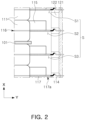
- FIG. 2 is a bottom view of a partial area of the battery module and illustrates that a bus bar assembly is illustrated in cross section.
- the battery module may include a cell assembly 110 having a plurality of battery cells 111 including a case 112 in which an electrode assembly 113 is accommodated, a sealing portion 115 formed by sealing the case 112, and an electrode lead 114 exposed to the outside of the case 112, a bus bar assembly 120 electrically connected to the electrode lead 114, a plate portion 130 covering the cell assembly 110 and the bus bar assembly 120, and a heat blocking member 140 disposed to face at least one of the electrode lead 114, the sealing portion 115, and the bus bar assembly 120.
- the heat blocking member 140 may be solid.
- the battery cell 111 may have a form in which a positive electrode plate, a negative electrode plate, a separator, and an electrolyte are disposed inside the case 112.
- the electrode assembly 113 may be comprised of a positive electrode plate, a negative electrode plate, and a separator interposed between the positive electrode plate and the negative electrode plate.
- the area in the case 112 where the electrode assembly 113 is accommodated may be an electrode assembly receiving portion (111a in FIG. 3 ).
- the battery cell 111 may include the electrode assembly receiving portion (111a in FIG. 3 ), a folding portion 116, and the sealing portion 115.
- the folding portion 116 may be an area formed by folding one side of the case 112. With the electrode assembly 113 placed on the case 112, one side of the case 112 is folded to form the folding portion 116, and with both ends of the case 112 placed facing each other, the sealing portion 115 may be formed by sealing the remaining area excluding the folding portion 116.
- the sealing portion 115 may be provided as a plurality of sealing portions 115 in the Y-Z plane.
- the plurality of sealing portions 115 may include a pair of sealing portions 115 connected to one side and the other side of the folding portion 116 in the Y-Z plane, respectively, and another sealing portion 115 connected to the pair of sealing portions 115 and facing the folding portion 116 with the electrode assembly 113 therebetween. Accordingly, the case 112 may be sealed by the sealing portion 115 and the folding portion 116.
- the sealing portion 115 may be an area formed by sealing the case 112 using a method such as heat fusion.
- the sealing portion 115 may be disposed in three edge areas of the case 112. One edge area may be an area where the positive electrode lead 114 protrudes from the case 112, another edge area may be an area where the negative electrode lead protrudes, and another edge area may be a topmost area of the case 112 in the height direction (Z-axis direction) of the battery cell 111. In an embodiment, the area of the sealing portion 115 disposed at the topmost part in the height direction of the battery cell 111, for example, the area of the sealing portion 115 facing the folding portion 116 with the electrode assembly 113 interposed therebetween may have a form in which the end of the case 112 is rolled and fixed with adhesive or the like.
- the battery cell 111 may have a shape in which respective electrode leads 114 connected to the positive and negative electrode plates protrude out of the case 112.
- the plurality of electrode leads 114 may have a bidirectional cell shape protruding from both sides of the battery cell 111, and may also have a unidirectional cell shape in which the plurality of electrode leads 114 all protrude from one side of the battery cell 111.
- a bidirectional cell type is used as an example.
- Some areas of the electrode lead 114 may be exposed to the outside of the case 112 before forming the sealing portion 115. With a portion of the electrode lead 114 exposed to the outside of the case 112, the case 112 may be sealed to seal the area where the electrode assembly 113 is accommodated.
- Electrode tabs may protrude from the positive and negative electrode plates, respectively. Respective electrode tabs may be combined with respective electrode leads 114, and a coupling portion 117a of the electrode tab and the electrode lead 114 may be located on a terrace portion 117.
- the terrace portion 117 may refer to the space remaining in the case 112, excluding the electrode assembly 113.
- the terrace portion 117 may include the sealing portion 115, and the coupling portion 117a of the electrode tab and the electrode lead 114 may be disposed in the terrace portion 117.
- an insulating member may be provided on the coupling portion 117a of the electrode tab and the electrode lead 114.
- the heat blocking member 140 may be disposed to face the terrace portion 117. Additionally, in an embodiment, the heat blocking member 140 may be disposed to face the coupling portion 117a of the electrode tab and the electrode lead 114.
- the cell assembly 110 may be formed by stacking a plurality of battery cells 111 formed as above. Among the plurality of battery cells 111, a pair of neighboring battery cells 111 may be placed such that the electrode assembly receiving portions (111a in FIG. 3 ) may face each other and the sealing portions 115 may face each other. The plurality of battery cells 111 may be stacked according to this principle.
- the bus bar assembly 120 may include a bus bar member 121 electrically connected to the electrode lead 114 and a bus bar plate 122 supporting the bus bar member 121.
- the electrode lead 114 may be connected to the bus bar member 121 by welding.
- the bus bar plate 122 may also be disposed between the battery cell 111 and the bus bar member 121, and may be provided as an insulating material and may perform an insulating function.
- the heat blocking member 140 may be disposed to face the bus bar assembly 120 and the sealing portion 115 facing the bus bar assembly 120.
- the heat blocking member 140 may be disposed to simultaneously face the bus bar assembly 120 and the sealing portion 115 facing the bus bar assembly 120.
- the sealing portion 115 disposed in the area where the electrode lead 114 connected to the positive electrode plate of the battery cell 111 is disposed may face the bus bar assembly 120 to which the electrode lead 114 connected to the positive electrode plate is connected.
- another sealing portion 115 disposed in the area where another electrode lead 114 connected to the negative electrode plate of the battery cell 111 is disposed may face a bus bar assembly 120 to which the electrode lead 114 connected to the negative electrode plate is connected.
- the pair of sealing portions 115 may be disposed to be spaced apart from each other with the electrode assembly 113 therebetween, and a pair of bus bar members 121 and a pair of bus bar plates 122 may also be disposed to be spaced apart from each other with the electrode assembly 113 therebetween.
- the plate portion 130 may further include a third plate member 133 disposed at the bottom of the battery module in the Z-axis direction and facing the bottom surface of the battery cell 111, and a fourth plate member 134 disposed at the top in the Z-axis direction and facing the top surface of the battery cell 111.
- the fourth plate member 134 may cover the top portion of the cell assembly 110, and may have a venting hole (not illustrated) formed for venting.
- An insulating material such as a mica sheet or a polycarbonate sheet may be disposed between the fourth plate member 134 and the cell assembly 110.
- this is not necessarily limited by the present disclosure, and may be appropriately selected and applied depending on the specifications of the battery module, the specifications of the battery pack formed by a plurality of battery modules, or the like.
- the transfer or propagation of this thermal event to other battery cells 111 should be minimized.
- the problem of preventing thermal events from transferring in the unit of the battery cell 111 may be significantly important to prevent thermal runaway of the battery module or battery pack.
- a battery module may include a plurality of heat blocking members 140. Additionally, each heat blocking member 140 may be respectively disposed between battery cells 111 of the cell assembly 110. In an embodiment, the heat blocking member 140 may be disposed between the electrode leads 114 of a pair of neighboring battery cells 111. In the case of a bidirectional battery cell, the heat blocking member 140 may be disposed between the positive electrode leads 114 and the negative electrode leads 114 of a pair of battery cells 111, respectively. The heat blocking member 140 may also be disposed between the negative electrode leads 114 in the same principle as between the positive electrode leads 114. Hereinafter, the positive electrode lead 114 will be described as an example.
- a pair of neighboring battery cells 111 may be placed so that the electrode assembly receiving portions (111a in FIG. 3 ) face each other and the electrode leads 114 face each other.
- a pad 101 may be disposed between the battery cells 111.
- the pad 101 may be formed of an insulating material and, for example, may be formed of a material containing mica.
- the pad 101 may perform various roles, such as cooling the battery cell 111, providing surface pressure to the battery cell 111, and the like, and depending on the specifications of the battery module and the like, the application, material, number, and the like thereof may be appropriately selected and applied.
- a pair of neighboring battery cells 111 may be placed such that the terrace portions 117 face each other and the electrode leads 114 also face each other.
- a separation space S may be formed between the terrace portions 117 and the electrode leads 114 of a pair of neighboring battery cells 111.
- the separation space S may include a first separation space S1 disposed at the top in the +X direction in FIG. 2 , a second separation space S2 disposed below the first separation space S1, and a third separation space S3 disposed below the second separation space S2.
- the separation space S may be formed respectively between the plurality of battery cells 111 according to this principle.
- the separation space S may be a space formed by the electrode assembly receiving portion (111a in FIG. 3 ) of a pair of neighboring battery cells 111, the terrace portion 117 of a pair of neighboring battery cells 111, the electrode lead 114 of a pair of neighboring battery cells 111, the bus bar member 121 and the bus bar plate 122.
- the separation space S may be covered by the electrode assembly receiving portion (111a in FIG. 3 ) of a pair of neighboring battery cells 111, the terrace portion 117 of a pair of neighboring battery cells 111, the electrode lead 114 of a pair of neighboring battery cells 111, the bus bar member 121 and the bus bar plate 122.
- the top portion of the separation space S may be covered with the fourth plate member (134 in FIG. 1 ).
- the bottom portion of the separation space S may be covered with a cooling plate (not illustrated) of the battery module or the third plate member (133 in FIG. 1 ) .
- the first separation space S1 and the second separation space S2 may share one battery cell 111. Additionally, the second separation space S2 and the third separation space S3 may also share one battery cell 111. According to this principle, a plurality of separation spaces (S) may be disposed in the cell assembly 110.
- FIG. 3 is a bottom view of a portion of the battery module into which the heat blocking member is inserted, and the bus bar assembly is illustrated in cross section. As illustrated in FIG. 3 , the heat blocking member 140 may be inserted into the plurality of respective spaces S.
- the heat blocking member 140 may be provided in a solid form.
- the heat blocking member 140 may be formed of a material having certain rigidity, certain strength, and certain hardness .
- the heat blocking member 140 may be formed of a material having enough rigidity, strength, and hardness to not damage the battery cell 111 or the bus bar assembly 120.
- the heat blocking member 140 may be formed of a material containing at least one of polyurethane, silica gel, a polymer material including glass fiber, and mica. Additionally, in an embodiment, the heat blocking member 140 may be formed of a material containing resin.
- the heat blocking member 140 may be formed of a material containing polyurethane, and in another embodiment, the heat blocking member 140 may be formed of a material in which polyurethane and a curing agent are mixed. The curing agent may contribute to improving the physical properties of the heat blocking member 140.
- the heat blocking member 140 formed of resin may be injection molded.
- the heat blocking member 140 may be pre-molded and have a solid form before assembly of the battery module is performed. Accordingly, since the molding work of the heat blocking member 140 is not performed within the battery module, the molding work of the heat blocking member 140 may be performed separately from the assembly work of the battery module.
- the heat blocking member 140 having a solid form may maintain the form thereof before insertion into the separation space S even after insertion into the separation space S.
- the heat blocking member 140 has no deformation of the outline thereof even after insertion into the separation space S, and the outline of the heat blocking member 140 before being inserted into the separation space S and the outline after being inserted into the separation space S may be the same.
- the heat blocking member 140 may be inserted into the separation space S to face the terrace portion 117 and the electrode lead 114 in the thickness direction cross section of the battery cell 111, for example, in the X-Y plane.
- the outer surface of the heat blocking member 140 inserted into the separation space S may be disposed close to the battery cell 111, the electrode lead 114 and the bus bar assembly 120.
- the heat blocking member 140 In the case of the heat blocking member 140 inserted into the separation space S where the pad 101 is disposed, the heat blocking member 140 may be disposed close to the end of the pad 101, but may be spaced apart from the end of the pad 101.
- the heat blocking member 140 that has been inserted between the battery cells 111 may cover at least a portion of the electrode lead 114. Accordingly, when venting gas generated in the electrode assembly receiving portion 111a of the battery cell 111 opens the case 112 of the battery cell 111 and is discharged in the direction of the electrode lead 114, the venting gas faces the heat blocking member 140.
- the heat blocking member 140 delays the propagation of high-temperature venting gas to other adjacent battery cell 111 areas and may also serve to cool the high-temperature venting gas.
- the transfer of heat, flame, and the like to other adjacent battery cells 111 may be delayed or significantly reduced.
- the heat blocking member 140 may be circular, but this is not necessarily limited by the present disclosure, and the cross-sectional shape of the heat blocking member 140 may be polygonal, which may be appropriately selected and applied considering the specifications of the battery module, venting characteristics, or the like.
- the thickness 145 for example, the diameter, of the heat blocking member 140 may be provided to have an intermediate fit or loose fit tolerance with the separation space S.
- the diameter of the thickest part of the heat blocking member 140 may be the axis, and the perimeter of the separation space S may be formed as follows.
- a border (L) of the separation space S may be formed by two sides parallel to the X-axis and spaced a certain distance apart from each other and by two sides that are connected to the above sides, are spaced a certain distance apart from each other and are parallel to the Y-axis.
- One border of the separation space S may be a line provided by extending the electrode assembly receiving portion 111a of the battery cell 111 in the X-axis direction, another border may be a line provided by extending the electrode lead 114 of one battery cell 111 in the Y-axis direction, another border may be a line provided by extending the area most protruding from the bus bar plate 122 toward the heat blocking member 140 in the X-axis direction, and another last border may be a line provided by extending the electrode lead 114 of the neighboring battery cell 111 in the Y-axis direction.
- the separation space S may become a hole.
- the diameter of the heat blocking member 140 and the width of the separation space may be provided to have a mutually intermediate fit or loose fit tolerance. Accordingly, the heat blocking member 140 may not be separated from the separation space S without damaging the battery cell 111 and the bus bar assembly 120.
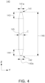
- FIG. 4 is a perspective view of the heat blocking member 140 according to an embodiment
- FIG. 5 is a front view of the battery cell 111 and the heat blocking member 140 according to an embodiment
- FIG. 6 is a perspective view of the heat blocking member 140 inserted between a pair of battery cells 111.
- the heat blocking member 140 may include at least one of a first inclined area 143 and a second inclined area 144 in the height direction cross section of the battery cell 111, for example, in the Y-Z plane.
- the heat blocking member 140 may include the first inclined area 143 inclined from one end 141 of the heat blocking member 140 toward the center (C) of the heat blocking member 140, and the second inclined area 144 inclined from the other end 142 toward the center (C) .
- the center (C) of the heat blocking member 140 may be the center of gravity.
- the heat blocking member 140 may be easily inserted into the separation space S.
- the directionality of the heat blocking member 140 may be eliminated when inserting the heat blocking member 140. This may improve the convenience of inserting the heat blocking member 140, and may contribute to improving the convenience of assembling the battery module and increasing the productivity of the battery module.
- the heat blocking member 140 may be provided in a form in which a thickness 141a at one end 141 and a thickness 142a at the other end 142 are the thinnest. Additionally, in an embodiment, the heat blocking member 140 may have the thickness 141a at one end 141 and the thickness 142a at the other end 142, which are the same as each other. Accordingly, since the heat blocking member 140 has a symmetrical shape with respect to the center (C) thereof, the directionality of the heat blocking member 140 maybe eliminated. Additionally, the first inclined area 143 and the second inclined area 144 may contribute to removing unnecessary parts from the heat blocking member 140 and may contribute to a slight weight reduction of the heat blocking member 140.
- one end 141 and the other end 142 of the heat blocking member 140 may be disposed outside the electrode lead 114.
- a height 146 of the heat blocking member 140 may have a value of 90% or more and 110% or less of a height 118 of the battery cell 111. In an embodiment, the height 146 of the heat blocking member 140 may be a value corresponding to 90% of the height of the battery cell 111. Therefore, the heat blocking member 140 may cover the electrode lead 114 and the terrace portion 117, and may also avoid interference with the fourth plate member (134 in FIG. 1 ) when the fourth plate member (134 in FIG. 1 ) is coupled to the top portion of the battery cell 111.
- the plate portion 130 may include the third plate member 133 disposed on the bottom of the battery cell 111.
- the third plate member 133 is provided as an insulating material and may be in contact with the bottom surface of the battery cell 111.
- the third plate member 133 may be provided with a cooling pipe (not illustrated) and the like therein, and the cooling pipe (not illustrated) may be connected to a coolant pump and the like so that coolant may circulate in the cooling pipe (not illustrated) . Accordingly, bottom cooling of the battery cell 111 may be performed.
- this is not necessarily limited by the present disclosure and may be appropriately selected and applied by those skilled in the art.
- the end of the heat blocking member 140 may be in contact with the third plate member 133 and supported by the third plate member 133.
- the height 146 of the heat blocking member 140 may be set to a value of 90% or more and 95% or less of the height of the battery cell 111. Accordingly, the heat blocking member 140 may be prevented from interfering with the case 112 of the battery cell 111.
- FIG. 7 schematically illustrates an assembly apparatus 200 for a battery module according to an embodiment
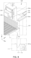
- FIG. 8 is a diagram illustrating the operating state of a cell assembly alignment portion 230.
- the assembly apparatus 200 for a battery module may include a device base 210, a worktable 220 on which a pre-battery module 100' is seated, and moved from the device base 210, the pre-battery module 100' including a cell assembly (110 in FIG. 1 ) including a plurality of battery cells (111 in FIG. 1 ) including a case (112 in FIG. 1 ) in which an electrode assembly 113 is accommodated, a sealing portion (115 in FIG. 1 ) formed by sealing the case (112 in FIG. 1 ) and an electrode lead (114 in FIG. 1 ) exposed to the outside of the case (112 in FIG. 1 ), a bus bar assembly (120 in FIG.
- a cell assembly alignment portion 230 including an alignment member 231 inserted into a separation space S formed by the sealing portion (115 in FIG. 1 ) of a pair of neighboring battery cells 111, the electrode lead (114 in FIG. 1 ) of a pair of battery cells 111, and the bus bar assembly (120 in FIG. 1 ), and a heat blocking member insertion portion 240 inserting a solid heat blocking member 140 into the separation space S when the alignment member 231 is separated from the separation space S.
- the pre-battery module 100' may be a battery module before the heat blocking member (140 in FIG. 1 ) is inserted.
- the assembly apparatus for a battery module may be made into a battery module by inserting or assembling a heat blocking member (140 in FIG. 1 ) into the pre-battery module 100'.
- the pre-battery module 100' mounted on the worktable 220 may be in a state in which only the fourth plate member (134 in FIG. 1 ) is assembled and the third plate member (133 in FIG. 1 ) may be in an unassembled state.
- the fourth plate member (134 in FIG. 1 ) may be in contact with the worktable 220, and the pre-battery module 100' may be upside down in the Z-axis direction.
- the operation of inverting the pre-battery module 100' and bringing the fourth plate member (134 in FIG. 1 ) into contact with the worktable 220 may be performed automatically or manually by an operator.
- the third plate member (133 in FIG. 1 ) may be combined with at least one of the first, second, and fourth plate members (131, 132, and 134 in FIG. 1 ) to cover the battery cell 111 after the insertion work of the heat blocking member (140 in FIG. 1 ) is completed.
- the battery cell 111 may be accommodated inside the first, second, third, and fourth plate members (131, 132, 133, and 134 in FIG. 1 ).
- the device base 210 and the worktable 220 on which the pre-battery module 100' is mounted may be provided with a device LM (Linear Motion) guide 211.
- the worktable 220 may be moved on the device base 210 by the device LM guide 211.
- the device LM guide 211 may be connected to a control unit (not illustrated), and the control unit (not illustrated) may control whether the worktable 220 moves, the moving distance, and the moving speed.
- the control unit (not illustrated) may be a Programmable Logic Controller (PLC) device.
- PLC Programmable Logic Controller
- the worktable 220 moves along the device base 210 and sequentially passes through the cell assembly alignment portion 230 and the heat blocking member insertion portion 240.
- the worktable 220 may be controlled to first pass through the cell assembly alignment portion 230 and then reach the heat blocking member insertion portion 240.
- the pre-battery module 100' may become a battery module equipped with a heat blocking member (140 in FIG. 1 ) after sequentially passing through the cell assembly alignment portion 230 and the heat blocking member insertion portion 240.
- the pre-battery module 100' in which insertion of the heat blocking member (140 in FIG. 1 ) has been completed may be transferred to a post process.
- the task of transferring the pre-battery module 100' to a post-process may also be automatically performed by the device LM guide 211 installed on the device base 210.
- the cell assembly alignment portion 230 includes an alignment member 231, and after inserting the alignment member 231 into the separation space S, the alignment member 231 may be removed again from the separation space S to complete the alignment of the battery cells 111.
- the cell assembly alignment portion 230 may include the alignment member 231 and an alignment member moving portion 232 that is connected to the alignment member 231 and moves the alignment member 231.
- the alignment member moving portion 232 may include a first direction moving portion 233 disposed in a direction parallel to the Y-axis and a second direction moving portion 234 disposed in a direction parallel to the Z-axis .
- the first direction moving portion 233 and the second direction moving portion 234 may be provided as LM guides, and may be connected to a control unit (not illustrated) and operation thereof may be controlled by the control unit (not illustrated) .
- a first moving frame 233a may be connected to the first direction moving portion 233.
- the first moving frame 233a may be moved in the +Y direction and -Y direction by the first direction moving portion 233.
- a second moving frame 234a may be connected to the first moving frame 233a.
- the second moving frame 234a may be provided with the above-described second direction moving portion 234.
- the second direction moving portion 234 may be provided in the second moving frame 234a in a direction parallel to the Z-axis.
- a third moving frame 235 may be engaged with the second direction moving portion 234.
- the third moving frame 235 may be moved by the second direction moving portion 234 in the +Z direction and -Z direction.
- An alignment frame 236 may be provided below the third moving frame 235.
- the alignment frame 236 is provided to have a certain length in the X-axis direction and may be fixed to the third moving frame 235. Therefore, the alignment frame 236 may be moved in the +Y, -Y, +Z, and -Z directions.
- the alignment member 231 may be fixed to the bottom portion of the alignment frame 236.
- the alignment members 231 may be provided in plural, and the plurality of alignment members 231 may be spaced apart from each other at a certain distance on the alignment frame 236.
- the thickness of the alignment member 231 may be at least the same as the thickness of the heat blocking member (140 in FIG. 9 ).
- the alignment member 231 may be moved along the alignment frame 236, and may be inserted between a plurality of battery cells 111 that have entered the bottom portion of the alignment member 231.
- the lowering operation of the alignment member 231 may be performed by the second direction moving portion 234.
- the number, shape and the like of the frames described above are according to an embodiment of the present disclosure, and the number, combination relationship, shape and the like of the frames may be replaced by various forms to implement movement of the alignment member.
- the alignment member 231 may be configured to move in directions of three axes, the X-axis, Y-axis and Z-axis.
- Various components may be combined to implement three-axis movement of the alignment member 231, and three-axes movements may also be obtained by combining multiple LM guides.
- the units for implementing the movement of the alignment member 231 are not necessarily limited by the present disclosure and may be appropriately selected and applied by those skilled in the art.
- the alignment member 231 may include an inclined section 231a inclined from an end toward the center thereof.
- the inclined section 231a of the alignment member 231 may facilitate the insertion of the alignment member 231 between the battery cells 111.
- the second direction moving portion 234 may be configured to move the alignment member 231 in the -Z direction until the end of the alignment member 231 contacts the bottom surface of the pre-battery module 100'. Additionally, the second direction moving portion 234 may be configured to raise the alignment member 231 in the +Z direction after the end of the alignment member 231 completes contact with the bottom surface of the pre-battery module (100' in FIG. 7 ).
- the alignment member 231 may be configured to be inserted into an area where the heat blocking member 140 is to be inserted later.
- the alignment member 231 may be inserted into an area where the terrace portions 117 of the neighboring battery cells 111 and the electrode leads 114 of the neighboring battery cells 111 face each other.
- the alignment member 231 may serve to keep the spacing between the battery cells 111 constant, to secure in advance the position where the heat blocking member (140 in FIG. 9 ) will be inserted, and to keep the volume of the separation space (S in FIG. 7 ) between the battery cells 111 constant.
- FIG. 9 schematically illustrates the heat blocking member insertion portion 240 according to an embodiment
- FIG. 10 is a diagram illustrating the operating state of the heat blocking member insertion portion 240 according to an embodiment.
- the heat blocking member insertion portion 240 may include a grip member 241 that holds the heat blocking member 140 and supports the heat blocking member 140, a pressing member 242 that pressurizes the heat blocking member 140 supported by the grip member 241 and pushes the same into the separation space (S in FIG. 7 ) between the battery cells 111, and a pressing member moving portion 540 connected to the pressing member 242 and moving the pressing member 242.
- the pressing member moving portion 540 may include a first fixed frame 541 and a second fixed frame 542.
- a driving member 248 and a pressure sensor 249 may be provided inside the second fixed frame 542.
- the pressure sensor 249 may be connected to the driving member 248 and be provided to sense the pressure applied to the driving member 248.
- the driving member 248 may be provided as a servo drive, motor, or the like, but is not necessarily limited by the present disclosure.
- the driving member 248 may be applied as a motor having a drive shaft.
- a reducer may be connected to the drive shaft as needed, and the motor is connected to a control unit (not illustrated) so that the rotation speed, rotation direction, and rotation status may be automatically controlled.
- the driving member 248 may be applied as a device such as a robot arm, CAM, or the like, and the type of the driving member 248 is not necessarily limited by the present disclosure.
- the driving member 248 is a motor will be described as an example.
- a gearbox 246 connected to the driving member 248 and receiving the power of the driving member 248 may be provided inside the first fixed frame 541.
- the gearbox 246 may be connected to the drive shaft of the drive member 248 and may have a gear member (not illustrated) embedded therein that may convert rotational motion into linear reciprocating motion in the +Z and -Z directions.
- the gear member may include various gears such as racks, pinions, velvet gears, helical gears, and the like.
- the role of the gearbox 246 is to convert rotational motion into linear motion, and the type and number of gear members are not limited as long as the role is possible.
- the pressure sensor 249 may be connected to the driving member 248 to obtain information on the pressure applied to the driving member 248.
- a separate sensor member (not illustrated) may be provided to obtain information such as the rotation direction, rotation speed and the like of the driving member 248, and in this case, the sensor member (not illustrated) may be connected to a control unit (not illustrated). Accordingly, the control unit may receive information related to the rotation direction and rotation speed as well as the pressure information of the driving member 248.
- control unit receives values measured by the pressure sensor 249 and the sensor member (not illustrated), and may control the driving member 248 by comparing pieces of preset information and measured information so that the measured information matches the preset information.
- the alignment member moving portion (232 in FIG. 8 ) and the pressing member moving portion 540 maybe connected to the control unit (not illustrated) and sequentially controlled. Accordingly, the convenience and precision of inserting the heat blocking member 140 between the battery cells 111 may be improved.
- a driving rod 246a may be connected to the gearbox 246.
- the driving rod 246a may be moved in the +Z and -Z directions.
- An elastic member 247 may be disposed on the outer periphery of the driving rod 246a.
- the pressing member 242 may be connected to the bottom portion of the driving rod 246a. One end of the pressing member 242 may be in contact with the heat blocking member 140. As the pressing member 242 is moved in the -Z direction while in contact with the heat blocking member 140, the heat blocking member 140 may be moved in the -Z direction. The heat blocking member 140 may be pressed by the pressing member 242 and inserted between the terrace portions 117 and between the electrode leads 114 of the battery cell 111. This operation may be performed by rotating the driving member 248 in one direction.
- the pressing member moving portion 540 may further include a second pressing frame 245 disposed below the second fixed frame 542 and a first pressing frame 244 disposed below the second pressing frame 245.
- the first pressing frame 244 may include a plurality of first through-holes 244a
- the second pressing frame 245 may include a plurality of second through-holes 245a.
- the first through-holes 244a and the second through-holes 245a may be provided in equal numbers, and the center of the first through-hole 244a and the center of the second through-hole 245a may be disposed on the same line in the Z-axis direction.
- the center of the first through-hole 244a and the center of the second through-hole 245a may be the center of the cross section of the first through-hole 244a and the center of the cross section of the second through-hole 245a on the X-Y plane.
- the pressing member 242 may be inserted into the first through-hole 244a and the second through-hole 245a.
- the inner diameter of the first through-hole 244a and the inner diameter of the second through-hole 245a may be greater than the thickness of the pressing member 242.
- the pressing member 242 may be moved in the +Z direction and -Z direction while inserted into the first through-hole 244a and the second through-hole 245a. Accordingly, even when the length of the pressing member 242 is long or a relatively large load is applied to the pressing member 242, meandering of the pressing member 242 may be prevented and the pressing member 242 may be prevented from buckling, which may contribute to improving the accuracy and precision of device operation.
- the grip member 241 may be provided in a split type.
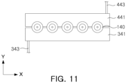
- the grip member 241 may include a first grip member 341 covering a certain area of the outer periphery of the heat blocking member 140, and a second grip member 441 facing the first grip member 341 and covering the outer peripheral area of the heat blocking member 140 that is not covered by the first grip member 341.
- a first grip member moving portion 343 may be connected to the first grip member 341, and a second grip member moving portion 443 may be connected to the second grip member 441.
- the first grip member moving portion 343 and the second grip member moving portion 443 may be applied as a cylinder, a robot arm, or the like, but this is not necessarily limited by the present disclosure.
- the first grip member moving portion 343 and the second grip member moving portion 443 may move the first grip member 341 and the second grip member 441, respectively, and the first grip member 341 and the second grip member 441 may be moved in a direction away from each other and in a direction closer to each other.
- the first grip member moving portion 343 and the second grip member moving portion 443 may move the first grip member 341 and the second grip member 441 in a direction to approach each other, to support and fix the heat blocking member 140.
- the heat blocking member 140 may be automatically supplied between the first grip member 341 and the second grip member 441 by a device such as a cassette (not illustrated), and may also be supplied manually by the operator.
- the pressing member 242 may push the heat blocking member 140 between the battery cells 111 while the first grip member 341 and the second grip member 441 support the heat blocking member 140.
- the pressing member 242 may push the heat blocking member 140 in, in a state in which the plurality of battery cells 111 are located below the first grip member 341 and the second grip member 441.
- a stopper 242a may be provided on the other end of the pressing member 242 not in contact with the heat blocking member 140.
- the stopper 242a may be formed by the pressing member 242 protruding a certain length in the radial direction of the pressing member 242.
- the diameter of the stopper 242a may be larger than the inner diameter of the second through-hole 245a.
- the stopper 242a may be provided to contact the second pressing frame 245 when the pressing member 242 has completely moved in the -Z direction. Accordingly, even when the pressing member 242 has completed the movement thereof, the pressing member 242 may be prevented from leaving the second pressing frame 245. Therefore, the reliability of the movement of the pressing member 242 may be increased.
- the stopper 242a may be fixed to the driving rod 246a, and the pressing member 242 may be moved along the driving rod 246a.
- the elastic member 247 may be disposed between the stopper 242a and the first fixed frame 541. The elastic member 247 may act as a buffer to absorb shock when the pressing member 242 moves, which may contribute to increased durability of the device.
- the pressing member 242 pushes the heat blocking member 140 in the -Z direction so that the heat blocking member 140 may be completely inserted between the battery cells 111.
- a pressure different from the preset pressure may be applied to the driving member 248. Then, this pressure information may be obtained from the pressure sensor 249, and the pressure sensor 249 may transmit a measured pressure value to the control unit (not illustrated).
- the control unit may raise the pressing member 242 in the +Z direction by immediately stopping the operation of the driving member 248 or rotating the driving member 248 in the other direction. Accordingly, damage to the battery cell 111 and the assembly apparatus 200 of the pre-battery module 100' may be prevented, and the reliability of the assembly apparatus 200 of the pre-battery module 100' may be increased.
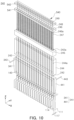
- FIG. 11 is a bottom view of the grip member according to an embodiment
- FIG. 12 is an operating state diagram of FIG. 11 .
- the first grip member 341 may include a first support groove 342 having a shape corresponding to the outer peripheral surface of the heat blocking member 140
- the second grip member 441 may include a second support groove 442 having a shape corresponding to the outer peripheral surface of the heat blocking member 140.
- the first support groove 342 and the second support groove 442 may have a semicircular shape.
- the radius of curvature of the first support groove 342 and the second support groove 442 may have a value at least equal to the radius of the heat blocking member 140.
- first grip member 341 and the second grip member 441 move in a direction closer to each other, so that the heat blocking member 140 may be inserted into the first support groove 342 and the second support groove 442.
- the operation of inserting the heat blocking member 140 into the first support groove 342 and the second support groove 442 may be performed manually by an operator, and may be performed automatically while the heat blocking member 140 is supported on a cassette (not illustrated) or a backup pin (not illustrated).
- a member capable of supporting the load of the heat blocking member 140 such as a backup pin (not illustrated), is provided at the bottom portion of the heat blocking member 140, and while the load of the heat blocking member 140 is supported, the first grip member 341 and the second grip member 441 may move to the position where the heat blocking member 140 is supported.
- the first grip member 341 and the second grip member 441 may move in a direction to approach each other.
- fixing and supporting the heat blocking member 140 by the first grip member 341 and the second grip member 441 may be completed.
- the pressing member (242 in FIG. 10 ) may push the heat blocking member 140 between the battery cells 111.
- FIG. 13 schematically illustrates an assembly apparatus 200 for a battery module according to another embodiment. As illustrated in FIG. 13 , the assembly apparatus 200 for a battery module according to another embodiment may further include an inspection unit 250.
- the battery module entering the inspection unit 250 may be the battery module 100 in a state in which a heat blocking member (140 in FIG. 1 ) is inserted.
- the inspection unit 250 may be provided on the device base 210, and the inspection unit 250 may be disposed to follow the heat blocking member insertion portion 240 in the direction of movement of the worktable 220. Therefore, by simply moving the pre-battery module 100' along the device base 210 while seated on the work table 220, not only the heat blocking member (140 in FIG. 1 ) insertion process but also the assembly state inspection process may be completed. Accordingly, the time consumed in the assembly and inspection work of the pre-battery module 100' or the battery module 100 may be shortened, and the convenience of assembly work and productivity of the battery module may be improved.
- FIG. 14 schematically illustrates the inspection unit 250 according to an embodiment.
- the inspection unit 250 may be provided to obtain at least one of the height information of the battery module 100, the height information of the battery cell 111, and the height information of the heat blocking member 140 from the device base 210.
- the inspection unit 250 may include a support frame 251 provided on the device base 210 and at least one position sensor 252 provided on the support frame 251.
- the support frame 251 may be installed in a certain section of the device base 210, and an inspection unit first LM guide 253 engaged with the worktable 220 may be installed on the support frame 251.
- the worktable 220 may enter the support frame 251 along the inspection unit first LM guide 253, but this is according to an embodiment, and thus the worktable 220 may be moved by a device other than the LM guide.
- an inspection unit moving frame 257 may be installed above the support frame 251, and an inspection unit second LM guide 256 may be installed on the inspection unit moving frame 257.
- a pair of sensor frames 254 may be engaged with the inspection unit second LM guide 256.
- a pair of sensor frames 254 may be connected to each other by a connection frame 255. However, the pair of sensor frames 254 may be provided integrally.
- a pair of sensor frames 254 may be moved in the +X direction and -X direction on the inspection unit moving frame 257 along the inspection unit second LM guide 256.
- a first position sensor 252a may be installed on one sensor frame 254, and a second position sensor 252b may be installed on the other sensor frame 254.
- the first position sensor 252a may face the electrode lead 114 on one side of the battery cell 111
- the second position sensor 252b may face the electrode lead on the other side of the battery cell 111.
- one electrode lead 114 may be a positive electrode lead
- the other electrode lead may be a negative electrode lead.
- position information on the positive electrode lead 114 side of the battery cell 111 and position information on the negative electrode lead 114 side may be obtained simultaneously.
- This position information may include the alignment state of the battery cells 111 and the insertion state of the heat blocking member 140 inserted between the battery cells 111.
- the first position sensor 252a and the second position sensor 252b may include at least one of a vision camera and a laser sensor.
- the first position sensor 252a and the second position sensor 252b may be connected to a control unit (not illustrated).
- the vision camera When applying the first position sensor 252a and the second position sensor 252b as a vision camera, the vision camera acquires image information of the battery module 100 and transmits or directly displays the alignment state of the battery module 100 and the insertion state of the heat blocking member 140 to the control unit (not illustrated), thereby allowing the alignment of the battery module 100 to be directly checked with the naked eye.
- information when the spacing between the battery cells 111 is inappropriate, the heat blocking member 140 is not disposed between the battery cells 111, or the location or number of the heat blocking members 140 is inappropriate, may be qualitatively obtained.
- a plurality of laser sensors may be provided, thereby obtaining X-axis, Y-axis, and Z-axis information of the battery module 100.
- the plurality of laser sensors may measure the distance to the battery module 100 or the heat blocking member 140 and transmit the measured distance to the control unit (not illustrated).
- the control unit (not illustrated) may be provided to determine the alignment state of the battery module 100 or the heat blocking member 140 as normal or abnormal by comparing preset information and measured information.
- the heat blocking member 140 may not be disposed between the battery cells 111, or the location or number of the heat blocking members 140 may be inappropriate may be quantitatively obtained.
- a vision camera and a laser sensor may be used in combination.
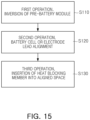
- FIG. 15 is a conceptual diagram of a method of assembling a battery module (100 in FIG. 13 ) according to an embodiment.
- the pre-battery module 100' is in a state before the heat blocking member (140 in FIG. 1 ) is inserted, and a method of assembling a battery module according to an embodiment of the present disclosure may relate to making a battery module by inserting or assembling a heat blocking member (140 in FIG. 1 ) into the pre-battery module 100'.
- the method of assembling a battery module (100 in FIG. 13 ) provides a method of inserting or assembling a heat blocking member (140 in FIG. 1 ) into a pre-battery module (100' in FIG. 13 ) including a cell assembly (110 in FIG. 1 ) including a plurality of battery cells (111 in FIG. 1 ) that include a case (112 in FIG. 1 ) containing an electrode assembly (113 in FIG. 1 ), a sealing portion (115 in FIG. 1 ) formed by sealing the case (112 in FIG. 1 ) and an electrode lead (114 in FIG. 1 ) exposed to the outside of the case (112 in FIG. 1 ), a bus bar assembly (120 in FIG.
- the method of assembling the battery module (100 in FIG. 13 ) may include, first, an operation (S110) of inverting the pre-battery module (100' in FIG. 13 ) in which the heat blocking member (140 in FIG. 1 ) is not inserted, an operation (S120) of aligning the plurality of battery cells (111 in FIG. 1 ), and an operation (S130) of inserting a solid heat blocking member into a separation space (S in FIG. 2 ) formed by the sealing portion (115 in FIG. 1 ) of a pair of neighboring battery cells (111 in FIG. 1 ), the electrode lead (114 in FIG. 1 ) of the pair of battery cells (111 in FIG. 1 ), and the bus bar assembly (120 in FIG. 1 ), to thereby be assembled as the battery module.
- the task of inserting the heat blocking member (140 in FIG. 1 ) into the pre-battery module (100' in FIG. 13 ) may be performed after the fourth plate member (134 in FIG. 1 ) is covered on the top portion of the pre-battery module (100' in FIG. 13 ) and also before the third plate member (133 in FIG. 5 ) is assembled to the bottom portion of the pre-battery module (100' in FIG. 13 ).
- the pre-battery module (100' in FIG. 13 ) may be inverted, such that the separation space (S in FIG. 2 ) is placed on the top portion of the pre-battery module (100' in FIG. 13 ) and the fourth plate member (134 in FIG. 1 ) is placed on the bottom of the pre-battery module (100' in FIG. 13 ).
- the operation (S120) of aligning the plurality of battery cells (111 in FIG. 1 ) may be performed.
- the positions of the battery cells (111 in FIG. 1 ) or the electrode leads (114 in FIG. 1 ) may be aligned to provide a space into which the heat blocking member (140 in FIG. 1 ) is inserted.
- the heat blocking member (140 in FIG. 1 ) may be uniformly and consistently inserted between the battery cells (114 in FIG. 1 ).
- the operation (S130) of inserting a solid heat blocking member (140 in FIG. 1 ) into a separation space formed by the sealing portion of a pair of neighboring battery cells (115 in FIG. 1 ), the electrode lead of the pair of battery cells (114 in FIG. 1 ), and the bus bar assembly (120 in FIG. 1 ) and of assembling the same as a battery module may be performed.
- the heat blocking member (140 in FIG. 1 ) may be inserted into the separation space (S in FIG. 2 ) in which the alignment is completed. This operation may be performed automatically or manually by an operator.
- FIG. 16 is a conceptual diagram of a method of assembling a battery module (100 in FIG. 13 ) according to another embodiment.
- a method of assembling the battery module (100 in FIG. 13 ) may further include an operation (S140) of obtaining at least one of the height information of the heat blocking member (140 in FIG. 1 ) inserted into the separation space (S in FIG. 2 ) and the height information of the battery cell (111 in FIG. 1 ), the operation (S140) being performed after the operation (S130) of inserting the solid heat blocking member (140 in FIG. 1 ) into the separation space (S in FIG. 2 ) formed by the sealing portion (115 in FIG. 1 ) of a pair of neighboring battery cells (111 in FIG. 1 ), the electrode lead (114 in FIG. 1 ) of the pair of battery cells (111 in FIG. 1 ), and the bus bar assembly (120 in FIG. 1 ) and of assembling the same as the battery module.
- the operation (S140) of acquiring at least one of the height information of the heat blocking member (140 in FIG. 1 ) and the height information of the battery cell (111 in FIG. 1 ) may be an operation of inspecting the battery module (100 in FIG. 13 ) in which the assembly of the heat blocking member (140 in FIG. 1 ) has been completed, to determine whether the battery module (100 in FIG. 13 ) is defective.
- This operation may be performed by at least one device selected from a vision camera or a laser sensor.
- the operation (S140) of acquiring at least one of the height information of the heat blocking member (140 in FIG. 1 ) and the height information of the battery cell (111 in FIG. 1 ) may be performed after aligning the plurality of battery cells.
- pieces of location information of the heat blocking member (140 in FIG. 1 ) and the battery cell (111 in FIG. 14 ) may be obtained together.
- the operation (S140) of acquiring at least one of the height information of the heat blocking member (140 in FIG. 1 ) inserted into the separation space (S in FIG. 2 ) and the height information of the battery cell (111 in FIG. 14 ) may include an operation of determining defective battery module (100 in FIG. 13 ) by comparing measured values of the height information of the battery cells (111 in FIG. 14 ) and a measured value of the height information of the heat blocking member (140 in FIG. 1 ) with preset setting values.
- This operation (S140) may be performed automatically using a PLC device, or the like.
- the present disclosure may be implemented in a variety of electrochemical devices, including, for example, digital cameras, cell phones, laptop computers, hybrid vehicles, electric vehicles, energy storage systems, wind generators, and other green tech power generators.
- the present disclosure may be implemented in various electrochemical devices utilizing secondary batteries, and may be implemented in devices for preventing climate change by suppressing air pollution and greenhouse gas emissions.
- a battery module having delayed thermal runaway and heat propagation is provided.
- a battery module in which thermal runaway and heat propagation are prevented and durability is improved is provided.
- a battery module having improved convenience and efficiency of assembly work is provided.
- a battery module that may be widely applied in green technology fields such as solar power generation and wind power generation is provided.
- a battery module that may be applied to eco-friendly devices such as eco-friendly electric vehicles, hybrid vehicles and the like to prevent climate change by suppressing air pollution and greenhouse gas emissions is provided.
Landscapes
- Chemical & Material Sciences (AREA)
- Chemical Kinetics & Catalysis (AREA)
- Electrochemistry (AREA)
- General Chemical & Material Sciences (AREA)
- Engineering & Computer Science (AREA)
- Manufacturing & Machinery (AREA)
- Physics & Mathematics (AREA)
- General Physics & Mathematics (AREA)
- Mechanical Engineering (AREA)
- Secondary Cells (AREA)
- Battery Mounting, Suspending (AREA)
- Connection Of Batteries Or Terminals (AREA)
Abstract
A battery module includes a cell assembly including a plurality of battery cells including a case containing an electrode assembly, a sealing portion formed by sealing the case, and an electrode lead exposed to an outside of the case, a bus bar assembly electrically connected to the electrode lead, a plate portion covering the cell assembly and the bus bar assembly, and at least one heat blocking member disposed to face the sealing portion and the bus bar assembly. The heat blocking member is solid.
Description
- The present disclosure relates to a battery module, an assembly apparatus for the battery module, and a method of assembling the battery module.
- Batteries are widely used in medium-to-large mechanical devices such as electric vehicles (EVs) as well as small electronic devices such as mobile phones and laptops, and have the advantage of being rechargeable and reusable.
- The present disclosure may be implemented in some embodiments to provide a battery module with delayed thermal runaway and heat propagation.
- The present disclosure may be implemented in some embodiments to provide a battery module in which thermal runaway and heat propagation are prevented and durability is improved.
- The present disclosure may be implemented in some embodiments to provide a battery module having improved convenience and efficiency of assembly work.
- The present disclosure may also be widely applied in green technology fields such as solar power generation and wind power generation.
- In addition, the present disclosure may be applied to eco-friendly devices such as eco-friendly electric vehicles, hybrid vehicles, and the like, to ameliorate climate change by suppressing air pollution and greenhouse gas emissions.
- In some embodiments of the present disclosure, a battery module includes a cell assembly including a plurality of battery cells including a case containing an electrode assembly, a sealing portion formed by sealing the case, and an electrode lead exposed to an outside of the case; a bus bar assembly electrically connected to the electrode lead; a plate portion covering the cell assembly and the bus bar assembly; and at least one heat blocking member disposed to face the sealing portion and the bus bar assembly. The heat blocking member is solid.
- The heat blocking member may be disposed in a separation space formed by a sealing portion of a pair of neighboring battery cells, an electrode lead of the pair of battery cells and the bus bar assembly, and may be inserted into the separation space in a solid state.
- The heat blocking member may be disposed to face the sealing portion and the bus bar assembly in a cross-section of the battery cell in a thickness direction.
- The heat blocking member may be provided in plural and respectively disposed between the pair of neighboring battery cells.
- A height of the heat blocking member in a cross section of the battery cell in a height direction may have a value of 90% or more and 110% or less of a height of the battery cell.
- The heat blocking member may include a first inclined area, inclined from one end toward a center of the heat blocking member based on a height direction, and may have a thinnest thickness on the one end.
- The heat blocking member may include a second inclined area, inclined from the other end toward the center thereof based on the height direction of the heat blocking member, and may have a thickness on the other end, being the same as the thickness on the one end.
- The heat blocking member may be formed of a material containing at least one of polyurethane, silica gel, a polymer material containing glass fiber, and mica.
- On the other hand, as another aspect, the present disclosure provides an assembly apparatus for a battery module.
- In some embodiments of the present disclosure, an assembly apparatus for a battery module includes a device base; a worktable provided with a pre- battery module seated thereon and moving on the device base, the pre-battery module including a cell assembly including a plurality of battery cells including a case containing an electrode assembly, a sealing portion formed by sealing the case and an electrode lead exposed to an outside of the case, a bus bar assembly electrically connected to the electrode lead, and a plate portion covering the cell assembly and the bus bar assembly; a cell assembly alignment portion including an alignment member inserted into a separation space formed by a sealing portion of a pair of the battery cells neighboring each other, electrode leads of the pair of battery cells, and the bus bar assembly; and a heat blocking member insertion portion inserting a solid type of a heat blocking member into the separation space when the alignment member is separated from the separation space and assembling as the battery module.
- The cell assembly alignment portion may further include an alignment member moving portion connected to the alignment member and moving the alignment member.
- The heat blocking member insertion portion may include a grip member supporting the heat blocking member; a pressing member pushing the heat blocking member supported by the grip member, into the separation space; and a pressing member moving portion connected to the pressing member and moving the pressing member.
- The heat blocking member insertion portion may further include a pressure sensor connected to at least one of the pressing member and the pressing member moving portion and obtaining information on pressure applied to at least one of the pressing member and the pressing member moving portion.
- The grip member may include a first grip member including a first support groove having a shape corresponding to an outer peripheral surface of the heat blocking member; and a second grip member including a second support groove having a shape corresponding to the outer peripheral surface of the heat blocking member, and the heat blocking member insertion portion may further include a grip member moving portion connected to the first grip member and the second grip member and moving the first grip member and the second grip member.
- The assembly apparatus for a battery module may further include an inspection unit provided on the device base and acquiring at least one of height information of the battery cell and height information of the heat blocking member when the battery module is seated on the worktable, the inspection unit may include a support frame provided on the device base; and a position sensor provided on the support frame and acquiring at least one of height information of the battery cell and height information of the heat blocking member when the worktable enters the support frame.
- On the other hand, as another aspect, the present disclosure provides a method of assembling a battery module.
- In some embodiments of the present disclosure, as a method of assembling a pre-battery module including a cell assembly containing a plurality of battery cells including a case containing an electrode assembly, a sealing portion formed by sealing the case and an electrode lead exposed to an outside of the case, a bus bar assembly electrically connected to the electrode lead, and a plate portion covering the cell assembly and the bus bar assembly, a method of assembling a battery module includes inverting the pre-battery module; aligning the plurality of battery cells; assembling the battery module by inserting at least one solid heat blocking member into a separation space formed by a sealing portion of a pair of neighboring battery cells, an electrode lead of the pair of battery cells, and the bus bar assembly; and the method of assembling a battery module may further include obtaining at least one of height information of the heat blocking member inserted into the separation space and height information of the battery cell, after the aligning the plurality of battery cells.
- Certain aspects, features, and advantages of the present disclosure are illustrated by the following detailed description with reference to the accompanying drawings.
-
FIG. 1 is an exploded perspective view of a battery module according to an embodiment. -
FIG. 2 is a bottom view of a portion of a battery module and illustrates that a bus bar assembly is illustrated in cross section. -
FIG. 3 is a bottom view of a portion of a battery module into which a heat blocking member is inserted and illustrates that a bus bar assembly is illustrated in cross section. -
FIG. 4 is a perspective view of a heat blocking member according to an embodiment. -
FIG. 5 is a front view of a battery cell and a heat blocking member according to an embodiment. -
FIG. 6 is a perspective view of a heat blocking member inserted between a pair of battery cells. -
FIG. 7 schematically illustrates an assembly apparatus for a battery module according to an embodiment. -
FIG. 8 is a diagram illustrating the operating state of a cell assembly alignment portion. -
FIG. 9 schematically illustrates a heat blocking member insertion portion according to an embodiment. -
FIG. 10 is a diagram illustrating the operating state of a heat blocking member insertion portion according to an embodiment. -
FIG. 11 is a bottom view of a grip member according to an embodiment. -
FIG. 12 is an operation state diagram ofFIG. 11 . -
FIG. 13 schematically illustrates an assembly apparatus for a battery module according to another embodiment. -
FIG. 14 schematically illustrates an inspection unit according to an embodiment. -
FIG. 15 is a conceptual diagram of a method of assembling a battery module according to an embodiment. -
FIG. 16 is a conceptual diagram of a method of assembling a battery module according to another embodiment. - Features of the present disclosure disclosed in this patent document are described by example embodiments with reference to the accompanying drawings.
- Battery cells constituting a battery may be manufactured by storing an electrode assembly comprised of a positive electrode plate, a negative electrode plate, and a separator in a case, injecting an electrolyte into the case, and then sealing the case.
- A battery module may be formed by stacking a plurality of battery cells, and a battery pack may be formed by gathering a plurality of battery modules.
- During use of a battery module or a battery pack, ignition may occur due to high-temperature venting gas, flame, sparks, or the like. Since a battery module or a battery pack has a structure in which multiple battery cells are gathered together, it is necessary to quickly prevent heat, flame, or sparks from ignited battery cells, from spreading or transferring to other battery cells.
- As such, delaying or preventing thermal runaway or thermal propagation in a battery module or a battery pack may be a very important factor in improving battery safety.
- To facilitate understanding of the description of embodiments of the present disclosure, elements indicated with the same reference numerals in the attached drawings are the same elements. Some components in the attached drawings are exaggerated, omitted, or schematically illustrated, and the size of each component does not completely reflect the actual size.
- Hereinafter, the present disclosure will be described in detail with reference to the attached drawings.
- Hereinafter, the X-axis illustrated in the drawing is the thickness direction of a
battery cell 111, the Y-axis is the longitudinal direction of thebattery cell 111, and the Z-axis is the height direction of thebattery cell 111. However, this is an arbitrarily set direction for convenience of description, and the above-mentioned directions may be changed. -
FIG. 1 is an exploded perspective view of abattery module 100 according to an embodiment, andFIG. 2 is a bottom view of a partial area of the battery module and illustrates that a bus bar assembly is illustrated in cross section. - As illustrated in
FIGS. 1 and2 , the battery module according to an embodiment may include acell assembly 110 having a plurality ofbattery cells 111 including acase 112 in which anelectrode assembly 113 is accommodated, asealing portion 115 formed by sealing thecase 112, and anelectrode lead 114 exposed to the outside of thecase 112, abus bar assembly 120 electrically connected to theelectrode lead 114, aplate portion 130 covering thecell assembly 110 and thebus bar assembly 120, and aheat blocking member 140 disposed to face at least one of theelectrode lead 114, thesealing portion 115, and thebus bar assembly 120. Theheat blocking member 140 may be solid. - The
battery cell 111 may have a form in which a positive electrode plate, a negative electrode plate, a separator, and an electrolyte are disposed inside thecase 112. Theelectrode assembly 113 may be comprised of a positive electrode plate, a negative electrode plate, and a separator interposed between the positive electrode plate and the negative electrode plate. The area in thecase 112 where theelectrode assembly 113 is accommodated may be an electrode assembly receiving portion (111a inFIG. 3 ). - The
battery cell 111 may include the electrode assembly receiving portion (111a inFIG. 3 ), afolding portion 116, and thesealing portion 115. Thefolding portion 116 may be an area formed by folding one side of thecase 112. With theelectrode assembly 113 placed on thecase 112, one side of thecase 112 is folded to form thefolding portion 116, and with both ends of thecase 112 placed facing each other, the sealingportion 115 may be formed by sealing the remaining area excluding thefolding portion 116. - The sealing
portion 115 may be provided as a plurality of sealingportions 115 in the Y-Z plane. The plurality of sealingportions 115 may include a pair of sealingportions 115 connected to one side and the other side of thefolding portion 116 in the Y-Z plane, respectively, and another sealingportion 115 connected to the pair of sealingportions 115 and facing thefolding portion 116 with theelectrode assembly 113 therebetween. Accordingly, thecase 112 may be sealed by the sealingportion 115 and thefolding portion 116. The sealingportion 115 may be an area formed by sealing thecase 112 using a method such as heat fusion. - In an embodiment, the sealing
portion 115 may be disposed in three edge areas of thecase 112. One edge area may be an area where thepositive electrode lead 114 protrudes from thecase 112, another edge area may be an area where the negative electrode lead protrudes, and another edge area may be a topmost area of thecase 112 in the height direction (Z-axis direction) of thebattery cell 111. In an embodiment, the area of the sealingportion 115 disposed at the topmost part in the height direction of thebattery cell 111, for example, the area of the sealingportion 115 facing thefolding portion 116 with theelectrode assembly 113 interposed therebetween may have a form in which the end of thecase 112 is rolled and fixed with adhesive or the like. - The
battery cell 111 may have a shape in which respective electrode leads 114 connected to the positive and negative electrode plates protrude out of thecase 112. The plurality of electrode leads 114 may have a bidirectional cell shape protruding from both sides of thebattery cell 111, and may also have a unidirectional cell shape in which the plurality of electrode leads 114 all protrude from one side of thebattery cell 111. In the present disclosure, a bidirectional cell type is used as an example. - Some areas of the
electrode lead 114 may be exposed to the outside of thecase 112 before forming the sealingportion 115. With a portion of theelectrode lead 114 exposed to the outside of thecase 112, thecase 112 may be sealed to seal the area where theelectrode assembly 113 is accommodated. - Electrode tabs may protrude from the positive and negative electrode plates, respectively. Respective electrode tabs may be combined with respective electrode leads 114, and a
coupling portion 117a of the electrode tab and theelectrode lead 114 may be located on aterrace portion 117. Theterrace portion 117 may refer to the space remaining in thecase 112, excluding theelectrode assembly 113. Theterrace portion 117 may include the sealingportion 115, and thecoupling portion 117a of the electrode tab and theelectrode lead 114 may be disposed in theterrace portion 117. In an embodiment, an insulating member may be provided on thecoupling portion 117a of the electrode tab and theelectrode lead 114. - The
heat blocking member 140 may be disposed to face theterrace portion 117. Additionally, in an embodiment, theheat blocking member 140 may be disposed to face thecoupling portion 117a of the electrode tab and theelectrode lead 114. - The
cell assembly 110 may be formed by stacking a plurality ofbattery cells 111 formed as above. Among the plurality ofbattery cells 111, a pair of neighboringbattery cells 111 may be placed such that the electrode assembly receiving portions (111a inFIG. 3 ) may face each other and the sealingportions 115 may face each other. The plurality ofbattery cells 111 may be stacked according to this principle. - The
bus bar assembly 120 may include abus bar member 121 electrically connected to theelectrode lead 114 and abus bar plate 122 supporting thebus bar member 121. Theelectrode lead 114 may be connected to thebus bar member 121 by welding. In an embodiment, thebus bar plate 122 may also be disposed between thebattery cell 111 and thebus bar member 121, and may be provided as an insulating material and may perform an insulating function. - In an embodiment, the
heat blocking member 140 may be disposed to face thebus bar assembly 120 and the sealingportion 115 facing thebus bar assembly 120. For example, theheat blocking member 140 may be disposed to simultaneously face thebus bar assembly 120 and the sealingportion 115 facing thebus bar assembly 120. For example, the sealingportion 115 disposed in the area where theelectrode lead 114 connected to the positive electrode plate of thebattery cell 111 is disposed may face thebus bar assembly 120 to which theelectrode lead 114 connected to the positive electrode plate is connected. In addition, another sealingportion 115 disposed in the area where anotherelectrode lead 114 connected to the negative electrode plate of thebattery cell 111 is disposed may face abus bar assembly 120 to which theelectrode lead 114 connected to the negative electrode plate is connected. In this manner, in the Y-Z plane, the pair of sealingportions 115 may be disposed to be spaced apart from each other with theelectrode assembly 113 therebetween, and a pair ofbus bar members 121 and a pair ofbus bar plates 122 may also be disposed to be spaced apart from each other with theelectrode assembly 113 therebetween. - Accordingly, the
heat blocking member 140 may be disposed in both the area where oneelectrode lead 114 of thebattery cell 111 is disposed and the area where theother electrode lead 114 is disposed. In an area where theelectrode lead 114 connected to the positive electrode plate and theelectrode lead 114 connected to the negative electrode plate are disposed, theheat blocking member 140 may be disposed to simultaneously face the sealingportion 115 and thebus bar assembly 120 disposed in the corresponding area. For example, theheat blocking member 140 may be disposed to face the sealingportion 115 disposed in the corresponding area and to also at least a portion of thebus bar assembly 120 disposed in the corresponding area, in the area where theelectrode lead 114 connected to the positive electrode plate and theelectrode lead 114 connected to the negative electrode plate are disposed. - The
plate portion 130 may be disposed to cover thecell assembly 110 and thebus bar assembly 120. In an embodiment, theplate portion 130 may include a plurality offirst plate members 131 facing thebus bar plate 122, and a plurality ofsecond plate members 132 facing anoutermost battery cell 111 on one side of thecell assembly 110 and anoutermost battery cell 111 on the other side of thecell assembly 110. - In an embodiment, the
plate portion 130 may further include athird plate member 133 disposed at the bottom of the battery module in the Z-axis direction and facing the bottom surface of thebattery cell 111, and afourth plate member 134 disposed at the top in the Z-axis direction and facing the top surface of thebattery cell 111. Thefourth plate member 134 may cover the top portion of thecell assembly 110, and may have a venting hole (not illustrated) formed for venting. An insulating material such as a mica sheet or a polycarbonate sheet may be disposed between thefourth plate member 134 and thecell assembly 110. However, this is not necessarily limited by the present disclosure, and may be appropriately selected and applied depending on the specifications of the battery module, the specifications of the battery pack formed by a plurality of battery modules, or the like. - Since the plurality of
battery cells 111 are disposed in a battery module or battery pack, in a case in which a thermal event such as a flame or fire occurs in one of thebattery cells 111, the transfer or propagation of this thermal event toother battery cells 111 should be minimized. The problem of preventing thermal events from transferring in the unit of thebattery cell 111 may be significantly important to prevent thermal runaway of the battery module or battery pack. - A battery module according to an embodiment may include a plurality of
heat blocking members 140. Additionally, eachheat blocking member 140 may be respectively disposed betweenbattery cells 111 of thecell assembly 110. In an embodiment, theheat blocking member 140 may be disposed between the electrode leads 114 of a pair of neighboringbattery cells 111. In the case of a bidirectional battery cell, theheat blocking member 140 may be disposed between the positive electrode leads 114 and the negative electrode leads 114 of a pair ofbattery cells 111, respectively. Theheat blocking member 140 may also be disposed between the negative electrode leads 114 in the same principle as between the positive electrode leads 114. Hereinafter, thepositive electrode lead 114 will be described as an example. - As illustrated in
FIG. 2 , a pair of neighboringbattery cells 111 may be placed so that the electrode assembly receiving portions (111a inFIG. 3 ) face each other and the electrode leads 114 face each other. In this case, apad 101 may be disposed between thebattery cells 111. Thepad 101 may be formed of an insulating material and, for example, may be formed of a material containing mica. Thepad 101 may perform various roles, such as cooling thebattery cell 111, providing surface pressure to thebattery cell 111, and the like, and depending on the specifications of the battery module and the like, the application, material, number, and the like thereof may be appropriately selected and applied. - A pair of neighboring
battery cells 111 may be placed such that theterrace portions 117 face each other and the electrode leads 114 also face each other. A separation space S may be formed between theterrace portions 117 and the electrode leads 114 of a pair of neighboringbattery cells 111. - For example, the separation space S may include a first separation space S1 disposed at the top in the +X direction in
FIG. 2 , a second separation space S2 disposed below the first separation space S1, and a third separation space S3 disposed below the second separation space S2. The separation space S may be formed respectively between the plurality ofbattery cells 111 according to this principle. - The separation space S may be a space formed by the electrode assembly receiving portion (111a in
FIG. 3 ) of a pair of neighboringbattery cells 111, theterrace portion 117 of a pair of neighboringbattery cells 111, theelectrode lead 114 of a pair of neighboringbattery cells 111, thebus bar member 121 and thebus bar plate 122. The separation space S may be covered by the electrode assembly receiving portion (111a inFIG. 3 ) of a pair of neighboringbattery cells 111, theterrace portion 117 of a pair of neighboringbattery cells 111, theelectrode lead 114 of a pair of neighboringbattery cells 111, thebus bar member 121 and thebus bar plate 122. The top portion of the separation space S may be covered with the fourth plate member (134 inFIG. 1 ). The bottom portion of the separation space S may be covered with a cooling plate (not illustrated) of the battery module or the third plate member (133 inFIG. 1 ) . - The first separation space S1 and the second separation space S2 may share one
battery cell 111. Additionally, the second separation space S2 and the third separation space S3 may also share onebattery cell 111. According to this principle, a plurality of separation spaces (S) may be disposed in thecell assembly 110. -
FIG. 3 is a bottom view of a portion of the battery module into which the heat blocking member is inserted, and the bus bar assembly is illustrated in cross section. As illustrated inFIG. 3 , theheat blocking member 140 may be inserted into the plurality of respective spaces S. - The
heat blocking member 140 may be provided in a solid form. Theheat blocking member 140 may be formed of a material having certain rigidity, certain strength, and certain hardness . In this case, theheat blocking member 140 may be formed of a material having enough rigidity, strength, and hardness to not damage thebattery cell 111 or thebus bar assembly 120. - In an embodiment, the
heat blocking member 140 may be formed of a material containing at least one of polyurethane, silica gel, a polymer material including glass fiber, and mica. Additionally, in an embodiment, theheat blocking member 140 may be formed of a material containing resin. - Additionally, in an embodiment, the
heat blocking member 140 may be formed of a material containing polyurethane, and in another embodiment, theheat blocking member 140 may be formed of a material in which polyurethane and a curing agent are mixed. The curing agent may contribute to improving the physical properties of theheat blocking member 140. Theheat blocking member 140 formed of resin may be injection molded. - The
heat blocking member 140 may be pre-molded and have a solid form before assembly of the battery module is performed. Accordingly, since the molding work of theheat blocking member 140 is not performed within the battery module, the molding work of theheat blocking member 140 may be performed separately from the assembly work of the battery module. - In addition, the
heat blocking member 140 having a solid form may maintain the form thereof before insertion into the separation space S even after insertion into the separation space S. For example, theheat blocking member 140 has no deformation of the outline thereof even after insertion into the separation space S, and the outline of theheat blocking member 140 before being inserted into the separation space S and the outline after being inserted into the separation space S may be the same. - In addition, the
heat blocking member 140 may be inserted into the separation space S to face theterrace portion 117 and theelectrode lead 114 in the thickness direction cross section of thebattery cell 111, for example, in the X-Y plane. The outer surface of theheat blocking member 140 inserted into the separation space S may be disposed close to thebattery cell 111, theelectrode lead 114 and thebus bar assembly 120. - In the case of the
heat blocking member 140 inserted into the separation space S where thepad 101 is disposed, theheat blocking member 140 may be disposed close to the end of thepad 101, but may be spaced apart from the end of thepad 101. - The
heat blocking member 140 that has been inserted between thebattery cells 111 may cover at least a portion of theelectrode lead 114. Accordingly, when venting gas generated in the electrodeassembly receiving portion 111a of thebattery cell 111 opens thecase 112 of thebattery cell 111 and is discharged in the direction of theelectrode lead 114, the venting gas faces theheat blocking member 140. Theheat blocking member 140 delays the propagation of high-temperature venting gas to otheradjacent battery cell 111 areas and may also serve to cool the high-temperature venting gas. - According to the
heat blocking member 140, when a thermal event occurs, the transfer of heat, flame, and the like to otheradjacent battery cells 111 may be delayed or significantly reduced. - In the cross-section of the
battery cell 111 in the thickness direction, theheat blocking member 140 may be circular, but this is not necessarily limited by the present disclosure, and the cross-sectional shape of theheat blocking member 140 may be polygonal, which may be appropriately selected and applied considering the specifications of the battery module, venting characteristics, or the like. - When the
heat blocking member 140 is circular in the thickness direction cross section of thebattery cell 111, thethickness 145, for example, the diameter, of theheat blocking member 140 may be provided to have an intermediate fit or loose fit tolerance with the separation space S. In the fitting tolerance of the shaft and the hole, the diameter of the thickest part of theheat blocking member 140 may be the axis, and the perimeter of the separation space S may be formed as follows. - In an embodiment, a border (L) of the separation space S may be formed by two sides parallel to the X-axis and spaced a certain distance apart from each other and by two sides that are connected to the above sides, are spaced a certain distance apart from each other and are parallel to the Y-axis.
- One border of the separation space S may be a line provided by extending the electrode
assembly receiving portion 111a of thebattery cell 111 in the X-axis direction, another border may be a line provided by extending theelectrode lead 114 of onebattery cell 111 in the Y-axis direction, another border may be a line provided by extending the area most protruding from thebus bar plate 122 toward theheat blocking member 140 in the X-axis direction, and another last border may be a line provided by extending theelectrode lead 114 of the neighboringbattery cell 111 in the Y-axis direction. In this manner, when one separation space S is replaced with a shape corresponding to an approximately quadrangular shape, the separation space S may become a hole. - In the tolerance of the shaft and the hole, the diameter of the
heat blocking member 140 and the width of the separation space may be provided to have a mutually intermediate fit or loose fit tolerance. Accordingly, theheat blocking member 140 may not be separated from the separation space S without damaging thebattery cell 111 and thebus bar assembly 120. - In the case in which the
pad 101 is disposed in the separation space S, a line extending from the end of thepad 101 in the X-axis direction may be one border of the separation space S. -
FIG. 4 is a perspective view of theheat blocking member 140 according to an embodiment,FIG. 5 is a front view of thebattery cell 111 and theheat blocking member 140 according to an embodiment, andFIG. 6 is a perspective view of theheat blocking member 140 inserted between a pair ofbattery cells 111. - As illustrated in
FIGS. 4 to 6 , theheat blocking member 140 may include at least one of a firstinclined area 143 and a secondinclined area 144 in the height direction cross section of thebattery cell 111, for example, in the Y-Z plane. - In an embodiment, the
heat blocking member 140 may include the firstinclined area 143 inclined from oneend 141 of theheat blocking member 140 toward the center (C) of theheat blocking member 140, and the secondinclined area 144 inclined from theother end 142 toward the center (C) . The center (C) of theheat blocking member 140 may be the center of gravity. - According to the first
inclined area 143 and the secondinclined area 144, theheat blocking member 140 may be easily inserted into the separation space S. In addition, since an inclined area is disposed no matter which direction theheat blocking member 140 is inserted, the directionality of theheat blocking member 140 may be eliminated when inserting theheat blocking member 140. This may improve the convenience of inserting theheat blocking member 140, and may contribute to improving the convenience of assembling the battery module and increasing the productivity of the battery module. - Additionally, in an embodiment, the
heat blocking member 140 may be provided in a form in which athickness 141a at oneend 141 and athickness 142a at theother end 142 are the thinnest. Additionally, in an embodiment, theheat blocking member 140 may have thethickness 141a at oneend 141 and thethickness 142a at theother end 142, which are the same as each other. Accordingly, since theheat blocking member 140 has a symmetrical shape with respect to the center (C) thereof, the directionality of theheat blocking member 140 maybe eliminated. Additionally, the firstinclined area 143 and the secondinclined area 144 may contribute to removing unnecessary parts from theheat blocking member 140 and may contribute to a slight weight reduction of theheat blocking member 140. - Between the
battery cells 111, oneend 141 and theother end 142 of theheat blocking member 140 may be disposed outside theelectrode lead 114. Aheight 146 of theheat blocking member 140 may have a value of 90% or more and 110% or less of aheight 118 of thebattery cell 111. In an embodiment, theheight 146 of theheat blocking member 140 may be a value corresponding to 90% of the height of thebattery cell 111. Therefore, theheat blocking member 140 may cover theelectrode lead 114 and theterrace portion 117, and may also avoid interference with the fourth plate member (134 inFIG. 1 ) when the fourth plate member (134 inFIG. 1 ) is coupled to the top portion of thebattery cell 111. - On the other hand, in an embodiment, the
plate portion 130 may include thethird plate member 133 disposed on the bottom of thebattery cell 111. Thethird plate member 133 is provided as an insulating material and may be in contact with the bottom surface of thebattery cell 111. In addition, in an embodiment, thethird plate member 133 may be provided with a cooling pipe (not illustrated) and the like therein, and the cooling pipe (not illustrated) may be connected to a coolant pump and the like so that coolant may circulate in the cooling pipe (not illustrated) . Accordingly, bottom cooling of thebattery cell 111 may be performed. However, this is not necessarily limited by the present disclosure and may be appropriately selected and applied by those skilled in the art. - On the other hand, when the
third plate member 133 is provided, the end of theheat blocking member 140 may be in contact with thethird plate member 133 and supported by thethird plate member 133. - As illustrated in
FIG. 6 , when a top end portion of thebattery cell 111 is in the form formed by rolling and pressing the sealingportion 115, theheight 146 of theheat blocking member 140 may be set to a value of 90% or more and 95% or less of the height of thebattery cell 111. Accordingly, theheat blocking member 140 may be prevented from interfering with thecase 112 of thebattery cell 111. - In inserting one
heat blocking member 140 between a pair ofbattery cells 111, when theheat blocking member 140 faces theelectrode lead 114 and theterrace portion 117, and in the case in which high-temperature venting gas flows out of thebattery cell 111 while opening theterrace portion 117, heat propagation and heat transfer between thebattery cells 111 may be blocked more efficiently. - As mentioned above, the
terrace portion 117 may include an area corresponding to the outer periphery of the electrodeassembly receiving portion 111a to the end of thecase 112 in the -Y direction. Additionally, a connection portion between theelectrode lead 114 and an electrode tab (not illustrated) may be disposed in theterrace portion 117. Additionally, theterrace portion 117 may include an area where thecase 112 is sealed in the Z-axis direction and the Y-axis direction. In this case, the sealingportion 115 disposed in theterrace portion 117 may have a certain width in the Y-axis direction and may be disposed continuously in the Z-axis direction. -
FIG. 7 schematically illustrates anassembly apparatus 200 for a battery module according to an embodiment, andFIG. 8 is a diagram illustrating the operating state of a cellassembly alignment portion 230. - As illustrated in
FIG. 7 , the assembly apparatus 200 for a battery module according to an embodiment may include a device base 210, a worktable 220 on which a pre-battery module 100' is seated, and moved from the device base 210, the pre-battery module 100' including a cell assembly (110 inFIG. 1 ) including a plurality of battery cells (111 inFIG. 1 ) including a case (112 inFIG. 1 ) in which an electrode assembly 113 is accommodated, a sealing portion (115 inFIG. 1 ) formed by sealing the case (112 inFIG. 1 ) and an electrode lead (114 inFIG. 1 ) exposed to the outside of the case (112 inFIG. 1 ), a bus bar assembly (120 inFIG. 1 ) electrically connected to the electrode lead (114 inFIG. 1 ), and a plate portion (130 inFIG. 1 ) covering the cell assembly (110 inFIG. 1 ) and the bus bar assembly (120 inFIG. 1 ), a cell assembly alignment portion 230 including an alignment member 231 inserted into a separation space S formed by the sealing portion (115 inFIG. 1 ) of a pair of neighboring battery cells 111, the electrode lead (114 inFIG. 1 ) of a pair of battery cells 111, and the bus bar assembly (120 inFIG. 1 ), and a heat blocking member insertion portion 240 inserting a solid heat blocking member 140 into the separation space S when the alignment member 231 is separated from the separation space S. - The pre-battery module 100' may be a battery module before the heat blocking member (140 in
FIG. 1 ) is inserted. The assembly apparatus for a battery module may be made into a battery module by inserting or assembling a heat blocking member (140 inFIG. 1 ) into the pre-battery module 100'. - When the pre-battery module 100' is provided with a third plate member (133 in
FIG. 1 ) and a fourth plate member (134 inFIG. 1 ), the pre-battery module 100' mounted on theworktable 220 may be in a state in which only the fourth plate member (134 inFIG. 1 ) is assembled and the third plate member (133 inFIG. 1 ) may be in an unassembled state. In this case, the fourth plate member (134 inFIG. 1 ) may be in contact with theworktable 220, and the pre-battery module 100' may be upside down in the Z-axis direction. The operation of inverting the pre-battery module 100' and bringing the fourth plate member (134 inFIG. 1 ) into contact with theworktable 220 may be performed automatically or manually by an operator. - The third plate member (133 in
FIG. 1 ) may be combined with at least one of the first, second, and fourth plate members (131, 132, and 134 inFIG. 1 ) to cover thebattery cell 111 after the insertion work of the heat blocking member (140 inFIG. 1 ) is completed. As a result, thebattery cell 111 may be accommodated inside the first, second, third, and fourth plate members (131, 132, 133, and 134 inFIG. 1 ). - On the other hand, the
device base 210 and theworktable 220 on which the pre-battery module 100' is mounted may be provided with a device LM (Linear Motion)guide 211. Theworktable 220 may be moved on thedevice base 210 by the device LMguide 211. The device LM guide 211 may be connected to a control unit (not illustrated), and the control unit (not illustrated) may control whether theworktable 220 moves, the moving distance, and the moving speed. In an embodiment, the control unit (not illustrated) may be a Programmable Logic Controller (PLC) device. - The
worktable 220 moves along thedevice base 210 and sequentially passes through the cellassembly alignment portion 230 and the heat blockingmember insertion portion 240. In an embodiment, theworktable 220 may be controlled to first pass through the cellassembly alignment portion 230 and then reach the heat blockingmember insertion portion 240. - The pre-battery module 100' may become a battery module equipped with a heat blocking member (140 in
FIG. 1 ) after sequentially passing through the cellassembly alignment portion 230 and the heat blockingmember insertion portion 240. - The pre-battery module 100' in which insertion of the heat blocking member (140 in
FIG. 1 ) has been completed may be transferred to a post process. The task of transferring the pre-battery module 100' to a post-process may also be automatically performed by the device LMguide 211 installed on thedevice base 210. - The cell
assembly alignment portion 230 includes analignment member 231, and after inserting thealignment member 231 into the separation space S, thealignment member 231 may be removed again from the separation space S to complete the alignment of thebattery cells 111. - In describing in more detail with reference to
FIG. 8 , the cellassembly alignment portion 230 may include thealignment member 231 and an alignmentmember moving portion 232 that is connected to thealignment member 231 and moves thealignment member 231. - In an embodiment, the alignment
member moving portion 232 may include a firstdirection moving portion 233 disposed in a direction parallel to the Y-axis and a seconddirection moving portion 234 disposed in a direction parallel to the Z-axis . The firstdirection moving portion 233 and the seconddirection moving portion 234 may be provided as LM guides, and may be connected to a control unit (not illustrated) and operation thereof may be controlled by the control unit (not illustrated) . - In an embodiment, a first moving
frame 233a may be connected to the firstdirection moving portion 233. The first movingframe 233a may be moved in the +Y direction and -Y direction by the firstdirection moving portion 233. - A second moving
frame 234a may be connected to the first movingframe 233a. The second movingframe 234a may be provided with the above-described seconddirection moving portion 234. The seconddirection moving portion 234 may be provided in the second movingframe 234a in a direction parallel to the Z-axis. - A third moving
frame 235 may be engaged with the seconddirection moving portion 234. The third movingframe 235 may be moved by the seconddirection moving portion 234 in the +Z direction and -Z direction. - An
alignment frame 236 may be provided below the third movingframe 235. Thealignment frame 236 is provided to have a certain length in the X-axis direction and may be fixed to the third movingframe 235. Therefore, thealignment frame 236 may be moved in the +Y, -Y, +Z, and -Z directions. - The
alignment member 231 may be fixed to the bottom portion of thealignment frame 236. Thealignment members 231 may be provided in plural, and the plurality ofalignment members 231 may be spaced apart from each other at a certain distance on thealignment frame 236. - The thickness of the
alignment member 231 may be at least the same as the thickness of the heat blocking member (140 inFIG. 9 ). Thealignment member 231 may be moved along thealignment frame 236, and may be inserted between a plurality ofbattery cells 111 that have entered the bottom portion of thealignment member 231. The lowering operation of thealignment member 231 may be performed by the seconddirection moving portion 234. However, the number, shape and the like of the frames described above are according to an embodiment of the present disclosure, and the number, combination relationship, shape and the like of the frames may be replaced by various forms to implement movement of the alignment member. - In an embodiment, the
alignment member 231 may be configured to move in directions of three axes, the X-axis, Y-axis and Z-axis. Various components may be combined to implement three-axis movement of thealignment member 231, and three-axes movements may also be obtained by combining multiple LM guides. However, the units for implementing the movement of thealignment member 231 are not necessarily limited by the present disclosure and may be appropriately selected and applied by those skilled in the art. - On the other hand, in an embodiment, the
alignment member 231 may include aninclined section 231a inclined from an end toward the center thereof. Theinclined section 231a of thealignment member 231 may facilitate the insertion of thealignment member 231 between thebattery cells 111. - The second
direction moving portion 234 may be configured to move thealignment member 231 in the -Z direction until the end of thealignment member 231 contacts the bottom surface of the pre-battery module 100'. Additionally, the seconddirection moving portion 234 may be configured to raise thealignment member 231 in the +Z direction after the end of thealignment member 231 completes contact with the bottom surface of the pre-battery module (100' inFIG. 7 ). - In an embodiment, the
alignment member 231 may be configured to be inserted into an area where theheat blocking member 140 is to be inserted later. Thealignment member 231 may be inserted into an area where theterrace portions 117 of the neighboringbattery cells 111 and the electrode leads 114 of the neighboringbattery cells 111 face each other. - The
alignment member 231 may serve to keep the spacing between thebattery cells 111 constant, to secure in advance the position where the heat blocking member (140 inFIG. 9 ) will be inserted, and to keep the volume of the separation space (S inFIG. 7 ) between thebattery cells 111 constant. -
FIG. 9 schematically illustrates the heat blockingmember insertion portion 240 according to an embodiment, andFIG. 10 is a diagram illustrating the operating state of the heat blockingmember insertion portion 240 according to an embodiment. - As illustrated in
FIGS. 9 and10 , the heat blockingmember insertion portion 240 may include agrip member 241 that holds theheat blocking member 140 and supports theheat blocking member 140, a pressingmember 242 that pressurizes theheat blocking member 140 supported by thegrip member 241 and pushes the same into the separation space (S inFIG. 7 ) between thebattery cells 111, and a pressingmember moving portion 540 connected to thepressing member 242 and moving thepressing member 242. - In an embodiment, the pressing
member moving portion 540 may include a first fixedframe 541 and a second fixedframe 542. A drivingmember 248 and apressure sensor 249 may be provided inside the second fixedframe 542. Thepressure sensor 249 may be connected to the drivingmember 248 and be provided to sense the pressure applied to the drivingmember 248. - In an embodiment, the driving
member 248 may be provided as a servo drive, motor, or the like, but is not necessarily limited by the present disclosure. - In an embodiment, the driving
member 248 may be applied as a motor having a drive shaft. A reducer may be connected to the drive shaft as needed, and the motor is connected to a control unit (not illustrated) so that the rotation speed, rotation direction, and rotation status may be automatically controlled. However, this is according to an embodiment, and the drivingmember 248 may be applied as a device such as a robot arm, CAM, or the like, and the type of the drivingmember 248 is not necessarily limited by the present disclosure. Hereinafter, the case where the drivingmember 248 is a motor will be described as an example. - A
gearbox 246 connected to the drivingmember 248 and receiving the power of the drivingmember 248 may be provided inside the first fixedframe 541. Thegearbox 246 may be connected to the drive shaft of thedrive member 248 and may have a gear member (not illustrated) embedded therein that may convert rotational motion into linear reciprocating motion in the +Z and -Z directions. The gear member may include various gears such as racks, pinions, velvet gears, helical gears, and the like. The role of thegearbox 246 is to convert rotational motion into linear motion, and the type and number of gear members are not limited as long as the role is possible. - The
pressure sensor 249 may be connected to the drivingmember 248 to obtain information on the pressure applied to the drivingmember 248. In an embodiment, a separate sensor member (not illustrated) may be provided to obtain information such as the rotation direction, rotation speed and the like of the drivingmember 248, and in this case, the sensor member (not illustrated) may be connected to a control unit (not illustrated). Accordingly, the control unit may receive information related to the rotation direction and rotation speed as well as the pressure information of the drivingmember 248. - In an embodiment, the control unit (not illustrated) receives values measured by the
pressure sensor 249 and the sensor member (not illustrated), and may control the drivingmember 248 by comparing pieces of preset information and measured information so that the measured information matches the preset information. - According to the above principle, the alignment member moving portion (232 in
FIG. 8 ) and the pressingmember moving portion 540 maybe connected to the control unit (not illustrated) and sequentially controlled. Accordingly, the convenience and precision of inserting theheat blocking member 140 between thebattery cells 111 may be improved. - A driving
rod 246a may be connected to thegearbox 246. The drivingrod 246a may be moved in the +Z and -Z directions. Anelastic member 247 may be disposed on the outer periphery of the drivingrod 246a. - The pressing
member 242 may be connected to the bottom portion of the drivingrod 246a. One end of thepressing member 242 may be in contact with theheat blocking member 140. As thepressing member 242 is moved in the -Z direction while in contact with theheat blocking member 140, theheat blocking member 140 may be moved in the -Z direction. Theheat blocking member 140 may be pressed by the pressingmember 242 and inserted between theterrace portions 117 and between the electrode leads 114 of thebattery cell 111. This operation may be performed by rotating the drivingmember 248 in one direction. - In an embodiment, the pressing
member moving portion 540 may further include a secondpressing frame 245 disposed below the second fixedframe 542 and a firstpressing frame 244 disposed below the secondpressing frame 245. - The first
pressing frame 244 may include a plurality of first through-holes 244a, and the secondpressing frame 245 may include a plurality of second through-holes 245a. The first through-holes 244a and the second through-holes 245a may be provided in equal numbers, and the center of the first through-hole 244a and the center of the second through-hole 245a may be disposed on the same line in the Z-axis direction. At this time, the center of the first through-hole 244a and the center of the second through-hole 245a may be the center of the cross section of the first through-hole 244a and the center of the cross section of the second through-hole 245a on the X-Y plane. - The pressing
member 242 may be inserted into the first through-hole 244a and the second through-hole 245a. The inner diameter of the first through-hole 244a and the inner diameter of the second through-hole 245a may be greater than the thickness of thepressing member 242. The pressingmember 242 may be moved in the +Z direction and -Z direction while inserted into the first through-hole 244a and the second through-hole 245a. Accordingly, even when the length of thepressing member 242 is long or a relatively large load is applied to thepressing member 242, meandering of thepressing member 242 may be prevented and thepressing member 242 may be prevented from buckling, which may contribute to improving the accuracy and precision of device operation. - In an embodiment, the
grip member 241 may be provided in a split type. Thegrip member 241 may include afirst grip member 341 covering a certain area of the outer periphery of theheat blocking member 140, and asecond grip member 441 facing thefirst grip member 341 and covering the outer peripheral area of theheat blocking member 140 that is not covered by thefirst grip member 341. - A first grip
member moving portion 343 may be connected to thefirst grip member 341, and a second gripmember moving portion 443 may be connected to thesecond grip member 441. The first gripmember moving portion 343 and the second gripmember moving portion 443 may be applied as a cylinder, a robot arm, or the like, but this is not necessarily limited by the present disclosure. - The first grip
member moving portion 343 and the second gripmember moving portion 443 may move thefirst grip member 341 and thesecond grip member 441, respectively, and thefirst grip member 341 and thesecond grip member 441 may be moved in a direction away from each other and in a direction closer to each other. - The first grip
member moving portion 343 and the second gripmember moving portion 443 may move thefirst grip member 341 and thesecond grip member 441 in a direction to approach each other, to support and fix theheat blocking member 140. - At this time, the
heat blocking member 140 may be automatically supplied between thefirst grip member 341 and thesecond grip member 441 by a device such as a cassette (not illustrated), and may also be supplied manually by the operator. - The pressing
member 242 may push theheat blocking member 140 between thebattery cells 111 while thefirst grip member 341 and thesecond grip member 441 support theheat blocking member 140. The pressingmember 242 may push theheat blocking member 140 in, in a state in which the plurality ofbattery cells 111 are located below thefirst grip member 341 and thesecond grip member 441.
In an embodiment, astopper 242a may be provided on the other end of thepressing member 242 not in contact with theheat blocking member 140. Thestopper 242a may be formed by the pressingmember 242 protruding a certain length in the radial direction of thepressing member 242. The diameter of thestopper 242a may be larger than the inner diameter of the second through-hole 245a. Thestopper 242a may be provided to contact the secondpressing frame 245 when thepressing member 242 has completely moved in the -Z direction. Accordingly, even when thepressing member 242 has completed the movement thereof, the pressingmember 242 may be prevented from leaving the secondpressing frame 245. Therefore, the reliability of the movement of thepressing member 242 may be increased. - In an embodiment, the
stopper 242a may be fixed to the drivingrod 246a, and thepressing member 242 may be moved along the drivingrod 246a. Theelastic member 247 may be disposed between thestopper 242a and the first fixedframe 541. Theelastic member 247 may act as a buffer to absorb shock when thepressing member 242 moves, which may contribute to increased durability of the device. - As illustrated in
FIG. 10 , the pressingmember 242 pushes theheat blocking member 140 in the -Z direction so that theheat blocking member 140 may be completely inserted between thebattery cells 111. - At this time, in a case in which the
heat blocking member 140 is not fully inserted between thebattery cells 111 and is hit by another obstacle or comes into contact with thebattery cell 111, a pressure different from the preset pressure may be applied to the drivingmember 248. Then, this pressure information may be obtained from thepressure sensor 249, and thepressure sensor 249 may transmit a measured pressure value to the control unit (not illustrated). - In the case in which the preset pressure value and the measured pressure value are different, the control unit (not illustrated) may raise the
pressing member 242 in the +Z direction by immediately stopping the operation of the drivingmember 248 or rotating the drivingmember 248 in the other direction. Accordingly, damage to thebattery cell 111 and theassembly apparatus 200 of the pre-battery module 100' may be prevented, and the reliability of theassembly apparatus 200 of the pre-battery module 100' may be increased. -
FIG. 11 is a bottom view of the grip member according to an embodiment, andFIG. 12 is an operating state diagram ofFIG. 11 . - As illustrated in
FIGS. 11 and12 , thefirst grip member 341 may include afirst support groove 342 having a shape corresponding to the outer peripheral surface of theheat blocking member 140, and thesecond grip member 441 may include asecond support groove 442 having a shape corresponding to the outer peripheral surface of theheat blocking member 140. - The
first support groove 342 and thesecond support groove 442 may have a semicircular shape. The radius of curvature of thefirst support groove 342 and thesecond support groove 442 may have a value at least equal to the radius of theheat blocking member 140. - Therefore, the
first grip member 341 and thesecond grip member 441 move in a direction closer to each other, so that theheat blocking member 140 may be inserted into thefirst support groove 342 and thesecond support groove 442. The operation of inserting theheat blocking member 140 into thefirst support groove 342 and thesecond support groove 442 may be performed manually by an operator, and may be performed automatically while theheat blocking member 140 is supported on a cassette (not illustrated) or a backup pin (not illustrated). - For example, a member capable of supporting the load of the
heat blocking member 140, such as a backup pin (not illustrated), is provided at the bottom portion of theheat blocking member 140, and while the load of theheat blocking member 140 is supported, thefirst grip member 341 and thesecond grip member 441 may move to the position where theheat blocking member 140 is supported. - As illustrated in
FIG. 12 , thefirst grip member 341 and thesecond grip member 441 may move in a direction to approach each other. When the movement of thefirst grip member 341 and thesecond grip member 441 is completed as illustrated inFIG. 11 , fixing and supporting theheat blocking member 140 by thefirst grip member 341 and thesecond grip member 441 may be completed. Then, the pressing member (242 inFIG. 10 ) may push theheat blocking member 140 between thebattery cells 111. -
FIG. 13 schematically illustrates anassembly apparatus 200 for a battery module according to another embodiment. As illustrated inFIG. 13 , theassembly apparatus 200 for a battery module according to another embodiment may further include aninspection unit 250. - The battery module entering the
inspection unit 250 may be thebattery module 100 in a state in which a heat blocking member (140 inFIG. 1 ) is inserted. - The
inspection unit 250 may be provided on thedevice base 210, and theinspection unit 250 may be disposed to follow the heat blockingmember insertion portion 240 in the direction of movement of theworktable 220. Therefore, by simply moving the pre-battery module 100' along thedevice base 210 while seated on the work table 220, not only the heat blocking member (140 inFIG. 1 ) insertion process but also the assembly state inspection process may be completed. Accordingly, the time consumed in the assembly and inspection work of the pre-battery module 100' or thebattery module 100 may be shortened, and the convenience of assembly work and productivity of the battery module may be improved. -
FIG. 14 schematically illustrates theinspection unit 250 according to an embodiment. - As illustrated in
FIG. 14 , theinspection unit 250 according to an embodiment may be provided to obtain at least one of the height information of thebattery module 100, the height information of thebattery cell 111, and the height information of theheat blocking member 140 from thedevice base 210. - In an embodiment, the
inspection unit 250 may include asupport frame 251 provided on thedevice base 210 and at least oneposition sensor 252 provided on thesupport frame 251. - First, the
support frame 251 may be installed in a certain section of thedevice base 210, and an inspection unitfirst LM guide 253 engaged with theworktable 220 may be installed on thesupport frame 251. Theworktable 220 may enter thesupport frame 251 along the inspection unitfirst LM guide 253, but this is according to an embodiment, and thus theworktable 220 may be moved by a device other than the LM guide. - In an embodiment, an inspection
unit moving frame 257 may be installed above thesupport frame 251, and an inspection unitsecond LM guide 256 may be installed on the inspectionunit moving frame 257. A pair of sensor frames 254 may be engaged with the inspection unitsecond LM guide 256. A pair of sensor frames 254 may be connected to each other by aconnection frame 255. However, the pair of sensor frames 254 may be provided integrally. - In an embodiment, a pair of sensor frames 254 may be moved in the +X direction and -X direction on the inspection
unit moving frame 257 along the inspection unitsecond LM guide 256. - A
first position sensor 252a may be installed on onesensor frame 254, and asecond position sensor 252b may be installed on theother sensor frame 254. Thefirst position sensor 252a may face theelectrode lead 114 on one side of thebattery cell 111, and thesecond position sensor 252b may face the electrode lead on the other side of thebattery cell 111. For example, oneelectrode lead 114 may be a positive electrode lead, and the other electrode lead may be a negative electrode lead. - Therefore, by moving the
sensor frame 254 in the +X direction and -X direction, position information on thepositive electrode lead 114 side of thebattery cell 111 and position information on thenegative electrode lead 114 side may be obtained simultaneously. This position information may include the alignment state of thebattery cells 111 and the insertion state of theheat blocking member 140 inserted between thebattery cells 111. - In an embodiment, the
first position sensor 252a and thesecond position sensor 252b may include at least one of a vision camera and a laser sensor. Thefirst position sensor 252a and thesecond position sensor 252b may be connected to a control unit (not illustrated). - When applying the
first position sensor 252a and thesecond position sensor 252b as a vision camera, the vision camera acquires image information of thebattery module 100 and transmits or directly displays the alignment state of thebattery module 100 and the insertion state of theheat blocking member 140 to the control unit (not illustrated), thereby allowing the alignment of thebattery module 100 to be directly checked with the naked eye. - For example, by a vision camera, information when the spacing between the
battery cells 111 is inappropriate, theheat blocking member 140 is not disposed between thebattery cells 111, or the location or number of theheat blocking members 140 is inappropriate, may be qualitatively obtained. - On the other hand, in the case of a laser sensor, a plurality of laser sensors may be provided, thereby obtaining X-axis, Y-axis, and Z-axis information of the
battery module 100. The plurality of laser sensors may measure the distance to thebattery module 100 or theheat blocking member 140 and transmit the measured distance to the control unit (not illustrated). The control unit (not illustrated) may be provided to determine the alignment state of thebattery module 100 or theheat blocking member 140 as normal or abnormal by comparing preset information and measured information. - For example, in the case of a laser sensor, it is possible to calculate distance values, coordinate values, and the like. and thus, information in cases where the spacing of the
battery cells 111 is inappropriate, theheat blocking member 140 may not be disposed between thebattery cells 111, or the location or number of theheat blocking members 140 may be inappropriate may be quantitatively obtained. - Additionally, in an embodiment, a vision camera and a laser sensor may be used in combination.
- On the other hand,
FIG. 15 is a conceptual diagram of a method of assembling a battery module (100 inFIG. 13 ) according to an embodiment. - The pre-battery module 100' is in a state before the heat blocking member (140 in
FIG. 1 ) is inserted, and a method of assembling a battery module according to an embodiment of the present disclosure may relate to making a battery module by inserting or assembling a heat blocking member (140 inFIG. 1 ) into the pre-battery module 100'. - As illustrated in
FIG. 15 , the method of assembling a battery module (100 inFIG. 13 ) according to an embodiment provides a method of inserting or assembling a heat blocking member (140 inFIG. 1 ) into a pre-battery module (100' inFIG. 13 ) including a cell assembly (110 inFIG. 1 ) including a plurality of battery cells (111 inFIG. 1 ) that include a case (112 inFIG. 1 ) containing an electrode assembly (113 inFIG. 1 ), a sealing portion (115 inFIG. 1 ) formed by sealing the case (112 inFIG. 1 ) and an electrode lead (114 inFIG. 1 ) exposed to the outside of the case (112 inFIG. 1 ), a bus bar assembly (120 inFIG. 1 ) electrically connected to the electrode lead (114 inFIG. 1 ), and a plate portion (130 inFIG. 1 ) covering the cell assembly (110 inFIG. 1 ) and the bus bar assembly (120 inFIG. 1 ), thereby assembling as the battery module (100 inFIG. 13 ). - The method of assembling the battery module (100 in
FIG. 13 ) may include, first, an operation (S110) of inverting the pre-battery module (100' inFIG. 13 ) in which the heat blocking member (140 inFIG. 1 ) is not inserted, an operation (S120) of aligning the plurality of battery cells (111 inFIG. 1 ), and an operation (S130) of inserting a solid heat blocking member into a separation space (S inFIG. 2 ) formed by the sealing portion (115 inFIG. 1 ) of a pair of neighboring battery cells (111 inFIG. 1 ), the electrode lead (114 inFIG. 1 ) of the pair of battery cells (111 inFIG. 1 ), and the bus bar assembly (120 inFIG. 1 ), to thereby be assembled as the battery module. - The task of inserting the heat blocking member (140 in
FIG. 1 ) into the pre-battery module (100' inFIG. 13 ) may be performed after the fourth plate member (134 inFIG. 1 ) is covered on the top portion of the pre-battery module (100' inFIG. 13 ) and also before the third plate member (133 inFIG. 5 ) is assembled to the bottom portion of the pre-battery module (100' inFIG. 13 ). - Since the top portion of the pre-battery module (100' in
FIG. 13 ) is covered with the fourth plate member (134 inFIG. 1 ), the pre-battery module (100' inFIG. 13 ) may be inverted, such that the separation space (S inFIG. 2 ) is placed on the top portion of the pre-battery module (100' inFIG. 13 ) and the fourth plate member (134 inFIG. 1 ) is placed on the bottom of the pre-battery module (100' inFIG. 13 ). - After completing the operation (S110) of inverting the pre-battery module (100' in
FIG. 13 ), the operation (S120) of aligning the plurality of battery cells (111 inFIG. 1 ) may be performed. In this operation, the positions of the battery cells (111 inFIG. 1 ) or the electrode leads (114 inFIG. 1 ) may be aligned to provide a space into which the heat blocking member (140 inFIG. 1 ) is inserted. According to the operation (S120) of aligning the plurality of battery cells (111 inFIG. 1 ), the heat blocking member (140 inFIG. 1 ) may be uniformly and consistently inserted between the battery cells (114 inFIG. 1 ). - After completing the operation (S120) of aligning the plurality of battery cells (111 in
FIG. 1 ), the operation (S130) of inserting a solid heat blocking member (140 inFIG. 1 ) into a separation space formed by the sealing portion of a pair of neighboring battery cells (115 inFIG. 1 ), the electrode lead of the pair of battery cells (114 inFIG. 1 ), and the bus bar assembly (120 inFIG. 1 ) and of assembling the same as a battery module may be performed. At this stage, the heat blocking member (140 inFIG. 1 ) may be inserted into the separation space (S inFIG. 2 ) in which the alignment is completed. This operation may be performed automatically or manually by an operator. -
FIG. 16 is a conceptual diagram of a method of assembling a battery module (100 inFIG. 13 ) according to another embodiment. - As illustrated in
FIG. 16 , a method of assembling the battery module (100 inFIG. 13 ) according to an embodiment may further include an operation (S140) of obtaining at least one of the height information of the heat blocking member (140 inFIG. 1 ) inserted into the separation space (S inFIG. 2 ) and the height information of the battery cell (111 inFIG. 1 ), the operation (S140) being performed after the operation (S130) of inserting the solid heat blocking member (140 inFIG. 1 ) into the separation space (S inFIG. 2 ) formed by the sealing portion (115 inFIG. 1 ) of a pair of neighboring battery cells (111 inFIG. 1 ), the electrode lead (114 inFIG. 1 ) of the pair of battery cells (111 inFIG. 1 ), and the bus bar assembly (120 inFIG. 1 ) and of assembling the same as the battery module. - The operation (S140) of acquiring at least one of the height information of the heat blocking member (140 in
FIG. 1 ) and the height information of the battery cell (111 inFIG. 1 ) may be an operation of inspecting the battery module (100 inFIG. 13 ) in which the assembly of the heat blocking member (140 inFIG. 1 ) has been completed, to determine whether the battery module (100 inFIG. 13 ) is defective. This operation may be performed by at least one device selected from a vision camera or a laser sensor. - Additionally, in an embodiment, the operation (S140) of acquiring at least one of the height information of the heat blocking member (140 in
FIG. 1 ) and the height information of the battery cell (111 inFIG. 1 ) may be performed after aligning the plurality of battery cells. In an embodiment, pieces of location information of the heat blocking member (140 inFIG. 1 ) and the battery cell (111 inFIG. 14 ) may be obtained together. - In addition, the operation (S140) of acquiring at least one of the height information of the heat blocking member (140 in
FIG. 1 ) inserted into the separation space (S inFIG. 2 ) and the height information of the battery cell (111 inFIG. 14 ) may include an operation of determining defective battery module (100 inFIG. 13 ) by comparing measured values of the height information of the battery cells (111 inFIG. 14 ) and a measured value of the height information of the heat blocking member (140 inFIG. 1 ) with preset setting values. This operation (S140) may be performed automatically using a PLC device, or the like. In an embodiment, when the height measurement value of the heat blocking member (140 inFIG. 1 ) is different from the preset height value of the heat blocking member (140 inFIG. 1 ), or when the height measurement value of the battery cell (111 inFIG. 14 ) is different from the preset height value of the battery cell (111 inFIG. 14 ), it may be judged as defective. - The present disclosure may be implemented in a variety of electrochemical devices, including, for example, digital cameras, cell phones, laptop computers, hybrid vehicles, electric vehicles, energy storage systems, wind generators, and other green tech power generators.
- Additionally, the present disclosure may be implemented in various electrochemical devices utilizing secondary batteries, and may be implemented in devices for preventing climate change by suppressing air pollution and greenhouse gas emissions.
- As set forth above, according to an example embodiment, a battery module having delayed thermal runaway and heat propagation is provided.
- A battery module in which thermal runaway and heat propagation are prevented and durability is improved is provided.
- A battery module having improved convenience and efficiency of assembly work is provided.
- In addition, according to example embodiments, a battery module that may be widely applied in green technology fields such as solar power generation and wind power generation is provided.
- In addition, according to example embodiments, a battery module that may be applied to eco-friendly devices such as eco-friendly electric vehicles, hybrid vehicles and the like to prevent climate change by suppressing air pollution and greenhouse gas emissions is provided.
- The content described above is merely an example of applying the principles of the present disclosure, and other configurations may be further included or replaced with other configurations without departing from the scope of the present disclosure.
- Only specific examples of implementations of certain embodiments are described. Variations, improvements and enhancements of the disclosed embodiments and other embodiments may be made based on the present disclosure. Additionally, the above-described embodiments may be implemented by deleting some components, and each embodiment may be implemented in combination with each other.
Claims (15)
- A battery module comprising:a cell assembly including a plurality of battery cells including a case containing an electrode assembly, a sealing portion formed by sealing the case, and an electrode lead exposed to an outside of the case;a bus bar assembly electrically connected to the electrode lead;a plate portion covering the cell assembly and the bus bar assembly; andat least one heat blocking member disposed to face the sealing portion and the bus bar assembly,wherein the heat blocking member is solid.
- The battery module of claim 1, wherein the heat blocking member is disposed in a separation space formed by a sealing portion of a pair of neighboring battery cells, an electrode lead of the pair of battery cells and the bus bar assembly, and is inserted into the separation space in a solid state.
- The battery module of claim 1 or 2, wherein the heat blocking member is disposed to face the sealing portion and the bus bar assembly in a cross-section of the battery cell in a thickness direction.
- The battery module of any one of the preceding claims, wherein the heat blocking member is provided in plural and respectively disposed between the pair of neighboring battery cells.
- The battery module of any one of the preceding claims, wherein a height of the heat blocking member in a cross section of the battery cell in a height direction has a value of 90% or more and 110% or less of a height of the battery cell.
- The battery module of any one of the preceding claims, wherein the heat blocking member includes a first inclined area, inclined from one end toward a center of the heat blocking member based on a height direction, and has a thinnest thickness on the one end.
- The battery module of claim 6, wherein the heat blocking member includes a second inclined area, inclined from the other end toward the center thereof based on the height direction of the heat blocking member, and has a thickness on the other end, being the same as the thickness on the one end.
- The battery module of any one of the preceding claims, wherein the heat blocking member is formed of a material containing at least one of polyurethane, silica gel, a polymer material containing glass fiber, and mica.
- An assembly apparatus for a battery module, comprising:a device base;a worktable provided with a pre-battery module seated thereon and moving on the device base, the pre-battery module including a cell assembly including a plurality of battery cells including a case containing an electrode assembly, a sealing portion formed by sealing the case and an electrode lead exposed to an outside of the case, a bus bar assembly electrically connected to the electrode lead, and a plate portion covering the cell assembly and the bus bar assembly;a cell assembly alignment portion including an alignment member inserted into a separation space formed by a sealing portion of a pair of the battery cells neighboring each other, electrode leads of the pair of battery cells, and the bus bar assembly; anda heat blocking member insertion portion inserting a solid type of a heat blocking member into the separation space when the alignment member is separated from the separation space and assembling as the battery module.
- The assembly apparatus for a battery module of claim 9, wherein the cell assembly alignment portion further includes an alignment member moving portion connected to the alignment member and moving the alignment member.
- The assembly apparatus for a battery module of claim 9 or 10, wherein the heat blocking member insertion portion includes,a grip member supporting the heat blocking member;a pressing member pushing the heat blocking member supported by the grip member, into the separation space; anda pressing member moving portion connected to the pressing member and moving the pressing member.
- The assembly apparatus for a battery module of claim 11, wherein the heat blocking member insertion portion further includes a pressure sensor connected to at least one of the pressing member and the pressing member moving portion and obtaining information on pressure applied to at least one of the pressing member and the pressing member moving portion.
- The assembly apparatus for a battery module of claim 11, wherein the grip member includes,a first grip member including a first support groove having a shape corresponding to an outer peripheral surface of the heat blocking member; anda second grip member including a second support groove having a shape corresponding to the outer peripheral surface of the heat blocking member, andthe heat blocking member insertion portion further includes a grip member moving portion connected to the first grip member and the second grip member and moving the first grip member and the second grip member.
- The assembly apparatus for a battery module of any one of claims 9 to 13, further comprising an inspection unit provided on the device base and acquiring at least one of height information of the battery cell and height information of the heat blocking member when the battery module is seated on the worktable,wherein the inspection unit includes,a support frame provided on the device base; anda position sensor provided on the support frame and acquiring at least one of height information of the battery cell and height information of the heat blocking member when the worktable enters the support frame.
- A method of assembling a battery module, as a method of assembling a pre-battery module including a cell assembly containing a plurality of battery cells including a case containing an electrode assembly, a sealing portion formed by sealing the case and an electrode lead exposed to an outside of the case, a bus bar assembly electrically connected to the electrode lead, and a plate portion covering the cell assembly and the bus bar assembly, the method comprising:inverting the pre-battery module;aligning the plurality of battery cells;assembling the battery module by inserting at least one solid heat blocking member into a separation space formed by a sealing portion of a pair of neighboring battery cells, an electrode lead of the pair of battery cells, and the bus bar assembly; andobtaining at least one of height information of the heat blocking member inserted into the separation space and height information of the battery cell, after the aligning the plurality of battery cells.
Applications Claiming Priority (1)
| Application Number | Priority Date | Filing Date | Title |
|---|---|---|---|
| KR1020230117270A KR20250034825A (en) | 2023-09-04 | 2023-09-04 | BATTERY MODULE, ASSEMBLY APPARATUS FOR BATTERY MODULE and ASSEMBLY METHOD OF BATTERY MODULE |
Publications (1)
| Publication Number | Publication Date |
|---|---|
| EP4517964A1 true EP4517964A1 (en) | 2025-03-05 |
Family
ID=90123576
Family Applications (1)
| Application Number | Title | Priority Date | Filing Date |
|---|---|---|---|
| EP24160557.5A Pending EP4517964A1 (en) | 2023-09-04 | 2024-02-29 | Battery module, assembly apparatus for battery module and assembly method of battery module |
Country Status (4)
| Country | Link |
|---|---|
| US (1) | US20250079580A1 (en) |
| EP (1) | EP4517964A1 (en) |
| KR (1) | KR20250034825A (en) |
| CN (1) | CN119560702A (en) |
Citations (3)
| Publication number | Priority date | Publication date | Assignee | Title |
|---|---|---|---|---|
| EP3343672A1 (en) * | 2016-02-12 | 2018-07-04 | LG Chem, Ltd. | Busbar for cooling battery cell and battery module using same |
| EP4002554A1 (en) * | 2019-10-04 | 2022-05-25 | Lg Energy Solution, Ltd. | Battery module, battery pack including battery module, and vehicle including battery pack |
| US20230170576A1 (en) * | 2021-09-16 | 2023-06-01 | Sk On Co., Ltd. | Battery Module |
-
2023
- 2023-09-04 KR KR1020230117270A patent/KR20250034825A/en active Pending
-
2024
- 2024-02-29 CN CN202410229066.1A patent/CN119560702A/en active Pending
- 2024-02-29 EP EP24160557.5A patent/EP4517964A1/en active Pending
- 2024-03-07 US US18/597,916 patent/US20250079580A1/en active Pending
Patent Citations (3)
| Publication number | Priority date | Publication date | Assignee | Title |
|---|---|---|---|---|
| EP3343672A1 (en) * | 2016-02-12 | 2018-07-04 | LG Chem, Ltd. | Busbar for cooling battery cell and battery module using same |
| EP4002554A1 (en) * | 2019-10-04 | 2022-05-25 | Lg Energy Solution, Ltd. | Battery module, battery pack including battery module, and vehicle including battery pack |
| US20230170576A1 (en) * | 2021-09-16 | 2023-06-01 | Sk On Co., Ltd. | Battery Module |
Also Published As
| Publication number | Publication date |
|---|---|
| CN119560702A (en) | 2025-03-04 |
| US20250079580A1 (en) | 2025-03-06 |
| KR20250034825A (en) | 2025-03-11 |
Similar Documents
| Publication | Publication Date | Title |
|---|---|---|
| US11843089B2 (en) | Robot comprising robot arm | |
| KR102015898B1 (en) | Folding Device for electrode lead Part of Battery Cell | |
| CN110915048B (en) | Unit cell alignment device and electrode assembly manufacturing method using same | |
| JP7570754B2 (en) | Electrode lead bending and welding device and electrode lead welding method using the same | |
| EP3093908A1 (en) | Battery pack | |
| EP4616993A1 (en) | Welding positioning device, battery production line and welding method | |
| KR102468028B1 (en) | Battery module | |
| KR102043114B1 (en) | Welding guide device for electrode lead of secondary battery cell and welding guide system using the same | |
| JP6578438B2 (en) | Battery module, battery pack including the battery module, and automobile including the battery pack | |
| WO2025152276A1 (en) | Paper stripping apparatus, paper stripping method, adhesive pasting device, and adhesive pasting method | |
| CN117049159B (en) | Grabbing and placing device, grabbing and placing method and battery production line | |
| EP4613418A1 (en) | Battery top cover welding system and battery top cover welding method | |
| US20250079580A1 (en) | Battery module, assembly apparatus for battery module and assembly method of battery module | |
| JP2024530496A (en) | Temperature detection member, battery module including same, and battery pack | |
| KR102036544B1 (en) | Device for Welding Electrode Tabs Comprising Vision Inspection Part | |
| CN220290878U (en) | Device for manufacturing unit cell | |
| EP4583263A1 (en) | Battery cell, battery cell case, and manufacturing method thereof | |
| US20260018732A1 (en) | Arrangement apparatus for battery cell assembly and assembly apparatus for battery module having the same and arrangement method of battery cell assembly | |
| KR102203400B1 (en) | The jig for battery cell attached | |
| CN117296184A (en) | Battery pack component with vibration absorption function and equipment and method for manufacturing the battery pack component | |
| KR20250088133A (en) | Battery module and welding method of case for battery module | |
| US20250096299A1 (en) | Cell assembly manufacturing device and cell assembly manufacturing method | |
| KR102708611B1 (en) | Battery module | |
| US20240387852A1 (en) | Battery cell manufacturing apparatus and battery cell manufacturing method using the same | |
| KR102359235B1 (en) | Lead automatic forming apparatus for assembling bus-bar and lead automatic forming method using the same |
Legal Events
| Date | Code | Title | Description |
|---|---|---|---|
| PUAI | Public reference made under article 153(3) epc to a published international application that has entered the european phase |
Free format text: ORIGINAL CODE: 0009012 |
|
| STAA | Information on the status of an ep patent application or granted ep patent |
Free format text: STATUS: THE APPLICATION HAS BEEN PUBLISHED |
|
| AK | Designated contracting states |
Kind code of ref document: A1 Designated state(s): AL AT BE BG CH CY CZ DE DK EE ES FI FR GB GR HR HU IE IS IT LI LT LU LV MC ME MK MT NL NO PL PT RO RS SE SI SK SM TR |
|
| STAA | Information on the status of an ep patent application or granted ep patent |
Free format text: STATUS: REQUEST FOR EXAMINATION WAS MADE |
|
| 17P | Request for examination filed |
Effective date: 20250814 |