EP4517960A1 - Battery cell, battery and electrical device - Google Patents
Battery cell, battery and electrical device Download PDFInfo
- Publication number
- EP4517960A1 EP4517960A1 EP23916747.1A EP23916747A EP4517960A1 EP 4517960 A1 EP4517960 A1 EP 4517960A1 EP 23916747 A EP23916747 A EP 23916747A EP 4517960 A1 EP4517960 A1 EP 4517960A1
- Authority
- EP
- European Patent Office
- Prior art keywords
- tab
- protection sheet
- battery cell
- body portion
- injection hole
- Prior art date
- Legal status (The legal status is an assumption and is not a legal conclusion. Google has not performed a legal analysis and makes no representation as to the accuracy of the status listed.)
- Pending
Links
Images








Classifications
-
- H—ELECTRICITY
- H01—ELECTRIC ELEMENTS
- H01M—PROCESSES OR MEANS, e.g. BATTERIES, FOR THE DIRECT CONVERSION OF CHEMICAL ENERGY INTO ELECTRICAL ENERGY
- H01M50/00—Constructional details or processes of manufacture of the non-active parts of electrochemical cells other than fuel cells, e.g. hybrid cells
- H01M50/10—Primary casings; Jackets or wrappings
- H01M50/102—Primary casings; Jackets or wrappings characterised by their shape or physical structure
- H01M50/103—Primary casings; Jackets or wrappings characterised by their shape or physical structure prismatic or rectangular
-
- H—ELECTRICITY
- H01—ELECTRIC ELEMENTS
- H01M—PROCESSES OR MEANS, e.g. BATTERIES, FOR THE DIRECT CONVERSION OF CHEMICAL ENERGY INTO ELECTRICAL ENERGY
- H01M50/00—Constructional details or processes of manufacture of the non-active parts of electrochemical cells other than fuel cells, e.g. hybrid cells
- H01M50/20—Mountings; Secondary casings or frames; Racks, modules or packs; Suspension devices; Shock absorbers; Transport or carrying devices; Holders
- H01M50/204—Racks, modules or packs for multiple batteries or multiple cells
- H01M50/207—Racks, modules or packs for multiple batteries or multiple cells characterised by their shape
- H01M50/209—Racks, modules or packs for multiple batteries or multiple cells characterised by their shape adapted for prismatic or rectangular cells
-
- H—ELECTRICITY
- H01—ELECTRIC ELEMENTS
- H01M—PROCESSES OR MEANS, e.g. BATTERIES, FOR THE DIRECT CONVERSION OF CHEMICAL ENERGY INTO ELECTRICAL ENERGY
- H01M50/00—Constructional details or processes of manufacture of the non-active parts of electrochemical cells other than fuel cells, e.g. hybrid cells
- H01M50/40—Separators; Membranes; Diaphragms; Spacing elements inside cells
- H01M50/471—Spacing elements inside cells other than separators, membranes or diaphragms; Manufacturing processes thereof
- H01M50/474—Spacing elements inside cells other than separators, membranes or diaphragms; Manufacturing processes thereof characterised by their position inside the cells
-
- H—ELECTRICITY
- H01—ELECTRIC ELEMENTS
- H01M—PROCESSES OR MEANS, e.g. BATTERIES, FOR THE DIRECT CONVERSION OF CHEMICAL ENERGY INTO ELECTRICAL ENERGY
- H01M50/00—Constructional details or processes of manufacture of the non-active parts of electrochemical cells other than fuel cells, e.g. hybrid cells
- H01M50/50—Current conducting connections for cells or batteries
- H01M50/531—Electrode connections inside a battery casing
-
- H—ELECTRICITY
- H01—ELECTRIC ELEMENTS
- H01M—PROCESSES OR MEANS, e.g. BATTERIES, FOR THE DIRECT CONVERSION OF CHEMICAL ENERGY INTO ELECTRICAL ENERGY
- H01M50/00—Constructional details or processes of manufacture of the non-active parts of electrochemical cells other than fuel cells, e.g. hybrid cells
- H01M50/50—Current conducting connections for cells or batteries
- H01M50/531—Electrode connections inside a battery casing
- H01M50/533—Electrode connections inside a battery casing characterised by the shape of the leads or tabs
-
- H—ELECTRICITY
- H01—ELECTRIC ELEMENTS
- H01M—PROCESSES OR MEANS, e.g. BATTERIES, FOR THE DIRECT CONVERSION OF CHEMICAL ENERGY INTO ELECTRICAL ENERGY
- H01M50/00—Constructional details or processes of manufacture of the non-active parts of electrochemical cells other than fuel cells, e.g. hybrid cells
- H01M50/50—Current conducting connections for cells or batteries
- H01M50/543—Terminals
- H01M50/547—Terminals characterised by the disposition of the terminals on the cells
- H01M50/55—Terminals characterised by the disposition of the terminals on the cells on the same side of the cell
-
- H—ELECTRICITY
- H01—ELECTRIC ELEMENTS
- H01M—PROCESSES OR MEANS, e.g. BATTERIES, FOR THE DIRECT CONVERSION OF CHEMICAL ENERGY INTO ELECTRICAL ENERGY
- H01M50/00—Constructional details or processes of manufacture of the non-active parts of electrochemical cells other than fuel cells, e.g. hybrid cells
- H01M50/50—Current conducting connections for cells or batteries
- H01M50/543—Terminals
- H01M50/552—Terminals characterised by their shape
- H01M50/553—Terminals adapted for prismatic, pouch or rectangular cells
-
- H—ELECTRICITY
- H01—ELECTRIC ELEMENTS
- H01M—PROCESSES OR MEANS, e.g. BATTERIES, FOR THE DIRECT CONVERSION OF CHEMICAL ENERGY INTO ELECTRICAL ENERGY
- H01M50/00—Constructional details or processes of manufacture of the non-active parts of electrochemical cells other than fuel cells, e.g. hybrid cells
- H01M50/60—Arrangements or processes for filling or topping-up with liquids; Arrangements or processes for draining liquids from casings
- H01M50/609—Arrangements or processes for filling with liquid, e.g. electrolytes
- H01M50/627—Filling ports
-
- B—PERFORMING OPERATIONS; TRANSPORTING
- B60—VEHICLES IN GENERAL
- B60L—PROPULSION OF ELECTRICALLY-PROPELLED VEHICLES; SUPPLYING ELECTRIC POWER FOR AUXILIARY EQUIPMENT OF ELECTRICALLY-PROPELLED VEHICLES; ELECTRODYNAMIC BRAKE SYSTEMS FOR VEHICLES IN GENERAL; MAGNETIC SUSPENSION OR LEVITATION FOR VEHICLES; MONITORING OPERATING VARIABLES OF ELECTRICALLY-PROPELLED VEHICLES; ELECTRIC SAFETY DEVICES FOR ELECTRICALLY-PROPELLED VEHICLES
- B60L50/00—Electric propulsion with power supplied within the vehicle
- B60L50/50—Electric propulsion with power supplied within the vehicle using propulsion power supplied by batteries or fuel cells
- B60L50/60—Electric propulsion with power supplied within the vehicle using propulsion power supplied by batteries or fuel cells using power supplied by batteries
-
- B—PERFORMING OPERATIONS; TRANSPORTING
- B60—VEHICLES IN GENERAL
- B60R—VEHICLES, VEHICLE FITTINGS, OR VEHICLE PARTS, NOT OTHERWISE PROVIDED FOR
- B60R16/00—Electric or fluid circuits specially adapted for vehicles and not otherwise provided for; Arrangement of elements of electric or fluid circuits specially adapted for vehicles and not otherwise provided for
- B60R16/02—Electric or fluid circuits specially adapted for vehicles and not otherwise provided for; Arrangement of elements of electric or fluid circuits specially adapted for vehicles and not otherwise provided for electric constitutive elements
- B60R16/03—Electric or fluid circuits specially adapted for vehicles and not otherwise provided for; Arrangement of elements of electric or fluid circuits specially adapted for vehicles and not otherwise provided for electric constitutive elements for supply of electrical power to vehicle subsystems or for
- B60R16/033—Electric or fluid circuits specially adapted for vehicles and not otherwise provided for; Arrangement of elements of electric or fluid circuits specially adapted for vehicles and not otherwise provided for electric constitutive elements for supply of electrical power to vehicle subsystems or for characterised by the use of electrical cells or batteries
-
- H—ELECTRICITY
- H01—ELECTRIC ELEMENTS
- H01M—PROCESSES OR MEANS, e.g. BATTERIES, FOR THE DIRECT CONVERSION OF CHEMICAL ENERGY INTO ELECTRICAL ENERGY
- H01M2220/00—Batteries for particular applications
- H01M2220/20—Batteries in motive systems, e.g. vehicle, ship, plane
-
- H—ELECTRICITY
- H01—ELECTRIC ELEMENTS
- H01M—PROCESSES OR MEANS, e.g. BATTERIES, FOR THE DIRECT CONVERSION OF CHEMICAL ENERGY INTO ELECTRICAL ENERGY
- H01M50/00—Constructional details or processes of manufacture of the non-active parts of electrochemical cells other than fuel cells, e.g. hybrid cells
- H01M50/20—Mountings; Secondary casings or frames; Racks, modules or packs; Suspension devices; Shock absorbers; Transport or carrying devices; Holders
- H01M50/258—Modular batteries; Casings provided with means for assembling
-
- H—ELECTRICITY
- H01—ELECTRIC ELEMENTS
- H01M—PROCESSES OR MEANS, e.g. BATTERIES, FOR THE DIRECT CONVERSION OF CHEMICAL ENERGY INTO ELECTRICAL ENERGY
- H01M50/00—Constructional details or processes of manufacture of the non-active parts of electrochemical cells other than fuel cells, e.g. hybrid cells
- H01M50/20—Mountings; Secondary casings or frames; Racks, modules or packs; Suspension devices; Shock absorbers; Transport or carrying devices; Holders
- H01M50/271—Lids or covers for the racks or secondary casings
-
- Y—GENERAL TAGGING OF NEW TECHNOLOGICAL DEVELOPMENTS; GENERAL TAGGING OF CROSS-SECTIONAL TECHNOLOGIES SPANNING OVER SEVERAL SECTIONS OF THE IPC; TECHNICAL SUBJECTS COVERED BY FORMER USPC CROSS-REFERENCE ART COLLECTIONS [XRACs] AND DIGESTS
- Y02—TECHNOLOGIES OR APPLICATIONS FOR MITIGATION OR ADAPTATION AGAINST CLIMATE CHANGE
- Y02E—REDUCTION OF GREENHOUSE GAS [GHG] EMISSIONS, RELATED TO ENERGY GENERATION, TRANSMISSION OR DISTRIBUTION
- Y02E60/00—Enabling technologies; Technologies with a potential or indirect contribution to GHG emissions mitigation
- Y02E60/10—Energy storage using batteries
Definitions
- This application pertains to the field of battery technologies and more specifically relates to a battery cell, a battery, and an electric apparatus.
- an electrolyte needs to be injected through an electrolyte injection hole of an end cover. During injection, the electrolyte will impact the electrode assembly, resulting in damage to an electrode plate or separator, and thus causing damage to or short circuit of a cell.
- Embodiments of this application are intended to provide a battery cell, a battery, and an electric apparatus, so as to solve the problem that in the related art, during injection, an electrolyte impacts an electrode assembly, thus causing damage to an electrode plate or separator.
- an embodiment of this application provides a battery cell.
- the battery cell includes: an electrode assembly including a body portion and a tab, where the body portion has a body end surface, and the tab is led out of the body end surface; and a housing having a first wall, where the first wall is provided with an electrolyte injection hole and an electrode terminal, and the tab is electrically connected to the electrode terminal; where the body portion has a first region corresponding to the electrolyte injection hole, and at least one surface of the tab is provided with a protection sheet, the protection sheet shielding at least part of the first region.
- the protection sheet is provided on the tab to protect the tab, and the protection sheet is made to shield at least part of the region, on the body portion of the electrode assembly, that corresponds to the electrolyte injection hole, so that during injection of an electrolyte, impact of the electrolyte on the body portion can be alleviated so as to well protect the electrode assembly, and the risk that an electrode plate or separator of the electrode assembly is broken through during injection of the electrolyte can be reduced or prevented.
- the protection sheet shields all of the first region.
- All of the first region of the body portion is shielded by the protection sheet, so that during injection of the electrolyte, the electrolyte only impacts the protection sheet and does not directly flush the body portion of the electrode assembly, so as to well protect the body portion, further reducing or preventing the risk that the electrode plate or separator of the electrode assembly is broken through during injection of the electrolyte.
- the tab includes a tab root portion connected to the body portion and a tab body led out of the tab root portion, where width of the tab root portion is greater than width of the tab body, and the protection sheet is affixed to the tab root portion.
- the tab root portion is provided to be connected to the body portion, and the width of the tab root portion is set to be greater than the width of the tab body, so that the current conducting capability of the tab can be enhanced.
- the tab body is provided to be connected to the electrode terminal on the first wall, so as to facilitate assembly and connection.
- the protection sheet is affixed to the tab root portion for the tab root portion to support the protection sheet, which can enhance strength of support to the protection sheet, so as to enhance flushing resistance against the electrolyte.
- a separator of the body portion exceeds the tab root portion in a direction in which the tab is led out.
- the separator of the body portion is made to exceed the tab root portion so that the tab root portion is embedded inside the separator, so as to enhance insulation and isolation, thereby reducing or preventing the risk of short circuit in the body portion.
- the electrical conductivity of the first conductive material for manufacturing the first tab is smaller. Providing the tab root portion on the first tab can enhance the current flow capacity of the first tab. In addition, the first tab can be set to be thinner to reduce space occupied, which in turn increases capacity density of the battery cell.
- the first protection sheet extending from the body end surface of the body portion to the first side surface can not only enhance the structural strength of the connection between the first protection sheet and the body portion, but also better protect the body end surface of the body portion, avoiding or alleviating the flushing of the electrolyte to the body end surface of the body portion, and in particular alleviating the flushing of the electrolyte to an edge of the body end surface close to the first side surface, so as to better protect the body portion.
- the protection sheets are affixed to surfaces, facing away from the first wall, of the two tabs adjacent to the electrolyte injection hole, and the protection sheet shields the first region of the electrode assembly in which the protection sheet is located.
- the shield plate is provided on the first wall to shield the electrolyte injection hole, which can provide buffering during injection of the electrolyte through the electrolyte injection hole.
- the end, away from the body portion, of the protection sheet adjacent to the electrolyte injection hole is located on a side of the shield plate, which allows the shield plate to extend between the ends, away from the body portion, of the two adjacent protection sheets, so that not only the electrolyte being injected can be buffered by the protection sheet, but also space utilization inside the housing can be improved, the capacity density of the battery cell can be improved, and the shield plate can be prevented from bursting the protection sheet.
- the protection sheets are disposed on surfaces, close to the first wall, of the tabs of the two electrode assemblies adjacent to the electrolyte injection hole.
- the electrolyte is more likely to flush the two electrode assemblies and tabs adjacent to the electrolyte injection hole, and the protection sheets being disposed on the surfaces, close to the first wall, of the two tabs adjacent to the electrolyte injection hole can provide good protection for the two tabs adjacent to the electrolyte injection hole, alleviating the flushing of the electrolyte to the tabs, and also alleviating the flushing of the electrolyte to the body portion due to the buffering of the protection sheet on the electrolyte.
- the protection sheets corresponding to the surfaces, close to the first wall, of the two tabs adjacent to the electrolyte injection hole are of a one-piece structure.
- the protection sheets corresponding to the surfaces, close to the first wall, of the two tabs adjacent to the electrolyte injection hole being arranged as a one-piece structure allows the protection sheet to shield the region corresponding to the electrolyte injection hole to alleviate the impact of the electrolyte, thereby protecting the body portion of the electrode assembly.
- the protection sheets being connected to corresponding tabs of the electrode assemblies facilitates the mounting and fixing of the protection sheets and improves the assembly efficiency.
- the body portion has a body side surface adjacent to the body end surface; and in a thickness direction of the body portion, an end of the protection sheet on the surface of the tab close to the first wall extends to the body side surface of the body portion adjacent to the end.
- the protection sheet and the tab are connected through adhesion; or the protection sheet and the tab are connected through ultrasonic welding.
- the protection sheet and the tab being connected through adhesion facilitates both connection and assembly.
- the protection sheet and the tab being connected through ultrasonic welding can enhance the strength of the connection between the protection sheet and the tab.
- an embodiment of this application provides a battery including the battery cell according to the foregoing embodiments.
- an embodiment of this application provides an electric apparatus including the battery according to the foregoing embodiment.
- first the terms “first”, “second”, and the like are merely intended to distinguish between different objects, and shall not be understood as any indication or implication of relative importance or any implicit indication of the number, sequence or primary-secondary relationship of the technical features indicated. Therefore, a feature limited by “first” or “second” may explicitly or implicitly include one or more features.
- the term "and/or" is only an associative relationship for describing associated objects, indicating that three relationships may be present.
- a and/or B may indicate the following three cases: presence of only A, presence of both A and B, and presence of only B.
- the character "/" in this specification generally indicates an "or" relationship between contextually associated objects.
- a plurality of means more than two (inclusive).
- a plurality of groups means more than two (inclusive) groups
- a plurality of pieces means more than two (inclusive) pieces.
- Several means one or more unless otherwise specifically stated.
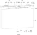
- the housing 40 has a first wall 401, the first wall 401 being a side wall of the housing 40.
- the first wall 401 is provided with an electrolyte injection hole 402 for injecting the electrolyte into the housing 40 through the electrolyte injection hole 402.
- the first wall 401 is provided with an electrode terminal 43, where the first wall 401 supports the electrode terminal 43, and the electrode terminal 43 is electrically connected to the tab 32.
- the protection sheet 33 is a sheet structure provided on the tab 32 to protect the tab 32.
- the protection sheet 33 may be an insulating film for providing good insulation and protection.
- the protection sheet 33 may be made of a material such as PP (Polypropylene, polypropylene), PE (Polyethylene, polyethylene), PET (polyethylene glycol terephthalate, polyethylene glycol terephthalate), or the like.
- the electrode terminal 43 refers to a conductive member provided on the first wall 401 of the housing 40.
- the electrode terminal 43 is connected to the tab 32 of the electrode assembly 30 to output electrical energy of the battery cell 200 or to charge the battery cell 200.
- the electrode terminal 43 of the battery cell 200 is typically provided in a quantity of two, and the two electrode terminals 43 are connected to the positive and negative electrode tabs 32 of the electrode assembly 30 respectively.
- the electrode terminal 43 connected to the positive electrode tab 32 is the positive electrode terminal 43
- the electrode terminal 43 connected to the negative electrode tab 32 is the negative electrode terminal 43.
- the electrode assembly 30 is connected to the electrode terminal 43 on the end cover 41 to form the battery cell 200, and certainly, the battery cell 200 may include other functional components.
- the two tabs 32 of opposite polarities of the electrode assembly 30 may be a first tab 321 and a second tab 322 respectively, where the first tab 321 may be the positive electrode tab 32 and the second tab 322 may be the negative electrode tab 32.
- the first tab 321 may be the negative electrode tab 32 and the second tab 322 may be the positive electrode tab 32.
- the electrode terminal 43 is also provided in a quantity of two.
- the electrode terminal 43 connected to the first tab 321 may be referred to as a first terminal 431
- the electrode terminal 43 connected to the second tab 322 may be referred to as a second terminal 432.
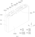
- the electrode assembly 30 has a height direction, a width direction, and a thickness direction.
- the direction Z is the height direction of the electrode assembly 30;
- the direction X is the width direction of the electrode assembly 30; and
- the direction Y is the thickness direction of the electrode assembly 30.
- the height direction of the electrode assembly 30 is also a height direction of the body portion 31 thereof;
- the width direction of the electrode assembly 30 is also a width direction of the body portion 31 thereof;
- the thickness direction of the electrode assembly 30 is also a thickness direction of the body portion 31 thereof.
- the battery cell 200 may include one or more electrode assemblies 30.
- the plurality of electrode assemblies 30 are divided into two groups, each group including at least one electrode assembly 30.
- the two electrode assemblies 30 are divided into two groups.
- the quantity of the electrode assemblies 30 is greater than two, at least one group includes at least two electrode assemblies 30, while the other group includes at least one electrode assembly 30.
- the quantity of electrode assemblies 30 is an even number, the quantity of electrode assemblies 30 in the two groups may be set to be the same.
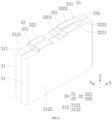
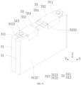
- the surface of the body portion 31 of the electrode assembly 30 on which the tab 32 is led out is defined as a body end surface 311 of the body portion 31.
- the body portion 31 has the body end surface 311, and the tab 32 is led out of the first end surface 311.
- the tab 32 is connected to the body portion 31 through the body end surface 311 of the body portion 31.
- the body end surface 311 of the body portion 31 is a surface at an end of the body portion 31 in the height direction (that is, the direction Z).
- the body portion 31 of the electrode assembly 30 has a body side surface 312, where the body side surface 312 is a surface on the body portion 31 adjacent to the body end surface 311.
- the body side surface 312 of the body portion 31 includes opposite first side surface 3121 and second side surface 3122, where the first side surface 3121 and the second side surface 3122 are both surfaces defined by the height direction (that is, the direction Z) and width direction (that is, the direction X) of the body portion 31. Therefore it can be learned that the normal direction of the first side surface 3121 and the second side surface 3122 is the thickness direction (that is, the direction Y) of the body portion 31, that is, distance between the first side surface 3121 and the second side surface 3122 is thickness of the body portion 31.
- opposite surfaces of the tab 32 are the first surface 3201 and the second surface 3202.
- the thickness direction of the body portion 31 is also the thickness direction of the tab 32
- the first surface 3201 of the tab 32 and the first side surface 3121 of the body portion 31 are located on a same side of the tab 32 in the thickness direction
- the second surface 3202 of the tab 32 and the second side surface 3122 of the body portion 31 are located on a same side of the tab 32 in the thickness direction.
- the tab 32 Since the tab 32 is typically connected to the electrode terminal 43 on the first wall 401 before assembly, and then the tab 32 is bent for the electrode assembly 30 to be mounted in the housing 40, as for the manufactured battery cell 200, the first surface 3201 of the tab 32 is a surface of the tab 32 facing away from the first wall 401, and the second surface 3202 of the tab 32 is a surface of the tab 32 close to the first wall 401.
- the battery cell 200 further includes a current collecting member 51.
- the current collecting member 51 is a conductive member connecting the tab 32 and the electrode terminal 43.
- the current collecting member 51 may be a structure such as a conductive sheet or a conductive adapter sheet.
- the current collecting member 51 connects the tab 32 and the electrode terminal 43 to facilitate the connection between the tab 32 and the electrode terminal 43, enabling a more stable connection. It can be understood that in some cases, the tab 32 may also be directly connected to the electrode terminal 43.
- the housing 40 includes a housing body 42 and an end cover 41, where the end cover 41 covers the housing body 42 to form the housing 40 structure.
- the electrode assembly 30 is mounted in the housing body 42, and the end cover 41 covers the housing body 42 so that the electrode assembly 30 is mounted in the housing 40.
- the housing body 42 is an assembly configured to fit with the end cover 41 to form the internal environment of the battery cell 200, where the formed internal environment may be configured to accommodate the electrode assembly 30, an electrolyte, and other components.
- the housing body 42 and the end cover 41 may be separate components, an opening may be provided on the housing body 42, and the end cover 41 covers the opening to form the internal environment of the battery cell 200.
- the housing body 42 may be of various shapes and sizes, such as a cuboid shape, a cylindrical shape, and a hexagonal prism shape. Specifically, the shape of the housing body 42 may be determined according to a specific shape and size of the battery cell 200.
- the housing body 42 may be made of various materials, such as copper, iron, aluminum, stainless steel, aluminum alloy, and plastic, which are not particularly limited in the embodiments of this application.
- the end cover 41 may further be provided with a pressure relief mechanism for releasing internal pressure when the internal pressure or a temperature of the battery cell 200 reaches a threshold.
- the battery cell 200 further includes a supporting plate 52, where the supporting plate 52 is mounted in the housing body 42 and can support the bottom of the body portion 31 of the electrode assembly 30, increasing the structural strength of the battery cell 200.
- the end cover 41 is provided with an electrolyte injection hole 402 and an electrode terminal 43.
- the end cover 41 is the first wall 401 of the housing 40. This facilitates the processing of the electrolyte injection hole 402 and the mounting of the electrode terminal 43 on the housing 40.
- one of the other side walls of the housing 40 may also be used as the first wall 401, for example, the bottom of the housing body 42 of the housing 40 may be used as the first wall 401, and the electrolyte injection hole 402 and the electrode terminal 43 are mounted on the bottom of the housing body 42.
- the end cover 41 being used as the first wall 401 of the housing 40 involves a relatively simple manufacturing process, and this facilitates the mounting of the electrode terminal 43, as well as the connection between the tab 32 the electrode terminal 43. Therefore, the following embodiments will provide detailed description with the end cover 41 used as the first wall 401 of the housing 40 as an example.
- the electrolyte injection hole 402 is provided on the end cover 41
- the electrode terminal 43 is mounted on the end cover 41
- the surface of the tab 32 facing away from the end cover 41 is the first surface 3201
- the surface of the tab 32 close to the end cover 41 is the second surface 3202.
- the protection sheet 33 may alternatively shield only part of the first region, so that the protection sheet 33 can provide certain blocking and buffering on the electrolyte being injected through the electrolyte injection hole 402, and can also reduce the impact of the electrolyte on the body portion 31 of the electrode assembly 30, so as to protect the body portion 31.
- the tab 32 includes a tab root portion 3232 and a tab body 3231, where the tab body 3231 is connected to the tab root portion 3232, the tab root portion 3232 is connected to the body portion 31, and the tab body 3231 is led out of the tab root portion 3232.
- the tab body 3231 is electrically connected to the electrode terminal 43 during use. Width of the tab root portion 3232 is greater than width of the tab body 3231, which can enhance the current conducting capability of the tab 32, allowing for thinner tab 32 and reducing space occupied. In addition, this can also enhance the structural strength at the connection between the tab root portion 3232 and the body portion 31. In other words, this enhances the structural strength of the body end surface 311 where the tab 32 is led out of the body portion 31.
- the tab body 3231 is provided for ease of connection to the first electrode terminal 43 on the first wall 401, facilitating assembly and connection.
- the separator of the body portion 31 exceeds the tab root portion 3232 in a direction in which the tab 32 is led out. As shown in the figure, in the height direction of the body portion 31, the separator exceeds the tab root portion 3232 so that the tab root portion 3232 is embedded inside the separator, so as to enhance insulation and isolation, thereby reducing or preventing the risk of short circuit in the body portion 31.
- the separator exceeds the tab root portion 3232 so that the tab root portion 3232 is embedded inside the separator, so as to enhance insulation and isolation, thereby reducing or preventing the risk of short circuit in the body portion 31.
- a plurality of tabs 32 are led out of the body portion 31 and these tabs 32 are stacked to form an entire tab 32, when the plurality of tab root portions 3232 are bent and stacked toward one side, the risk of short circuit of the body portion 31 can be better reduced or avoided, thus improving safety.
- the first tab 321 is made of a first conductive material
- the second tab 322 is made of a second conductive material
- electrical conductivity of the first conductive material is less than electrical conductivity of the second conductive material
- the first tab 321 has the tab root portion 3232.
- the electrical conductivity of the first conductive material for manufacturing the first tab 321 is smaller.
- the first tab 321 including the tab root portion 3232 enables the current flow capacity of the first tab 321 to be enhanced.
- the first tab 321 can be set to be thinner to reduce space occupied, which in turn increases capacity density of the battery cell 200.
- the first tab 321 may be provided with a protection sheet 33 to protect the first tab 321.
- the second tab 322 may be provided with a protection sheet 33 to protect the second tab 322.
- the protection sheet 33 and the tab 32 may be connected through adhesion.
- the protection sheet 33 and the tab 32 being connected through adhesion facilitates both connection and assembly. It can be understood that the protection sheet 33 and the tab 32 are connected through ultrasonic welding. The protection sheet 33 and the tab 32 being connected through ultrasonic welding can enhance the strength of the connection between the protection sheet 33 and the tab 32.
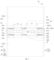
- width D1 of the protection sheet 33 on the first tab 321 is greater than 40 mm, for example, the width D1 of the protection sheet 33 on the first tab 321 may be set to 40 mm, 41 mm, 42 mm, 43 mm, 44 mm, 45 mm, 46 mm, 47 mm, 48 mm, 49 mm, 50 mm, 51 mm, 52 mm, 53 mm, 54 mm, 55 mm, 56 mm, 57 mm, 58 mm, 59 mm, 60 mm, or the like, so as to guarantee the width of the protection sheet 33, facilitating extension of the protection sheet 33 to the region corresponding to the electrolyte injection hole 402.
- a width D1 direction of the protection sheet 33 is consistent with the width direction of the body portion 31.
- the first protection sheet 331 may be affixed to the tab root portion 3232 of the first tab 321 to enhance the strength of support to the first protection sheet 331 through the tab root portion 3232, thereby enhancing the flushing resistance of the first protection sheet 331 against the electrolyte.
- the first protection sheet 331 covers the first surface 3201 of the tab 32.
- the first protection sheet 331 being made to cover the first surface 3201 of the tab 32 can better protect the tab 32 and enhance the structural strength of the connection between the first protection sheet 331 and the tab 32.
- the current collecting member 51 when the current collecting member 51 connects the tab 32 and the corresponding electrode terminal 43, the current collecting member 51 may be connected to the second surface 3202 of the tab 32, facilitating electrical connection between the tab 32 and the electrode terminal 43.
- the electrode assembly 30 further includes an insulating sheet 34, the insulating sheet 34 wrapping around the body portion 31 to bind the body portion 31 of the electrode assembly 30 and well protect the body portion 31.
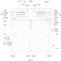
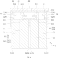
- the first tabs 321 of the two electrode assemblies 30 of the battery cell 200 are disposed adjacent to the electrolyte injection hole 402, the first tabs 321 are provided with the protection sheets 33, and the protection sheets 33 are made to shield the first regions on the corresponding body portions 31, so as to protect the body portions 31 and first tabs 321 of the electrode assemblies 30.
- the second tab 322 of the electrode assembly 30 is disposed adjacent to the electrolyte injection hole 402, the second tab 322 may also be provided with the protection sheet 33 such that the protection sheet 33 on the second tab 322 shields the first region.
- the first surfaces 3201 of the two tabs 32 adjacent to the electrolyte injection hole 402 are affixed with the protection sheets 33, and the protection sheets 33 shield regions that are on the body portions 31 of the electrode assemblies 30 in which the protection sheets 33 are located and correspond to the electrolyte injection hole 402.
- the protection sheets 33 are made to shield the first regions on the body portions 31 of the electrode assemblies 30 in which the protection sheets 33 are located.
- the first tabs 321 of the two electrode assemblies 30 of the battery cell 200 are disposed adjacent to the electrolyte injection hole 402, and the first surfaces 3201 of the first tabs 321 are affixed with the first protection sheets 331 for the first protection sheets 331 to protect the first tabs 321 and buffer the electrolyte being injected through the electrolyte injection hole 402, so as to protect the body portions 31 of the electrode assemblies 30.
- the protection sheets 33 may be separately provided on the tabs 32 of the electrode assemblies 30, and area of each protection sheet 33 may be made to be smaller, conducive to saving materials and reducing costs, and the protection sheet 33 with smaller area being used also facilitates mounting of the protection sheet 33.
- the first protection sheets 331 are affixed to the first tabs 321 of the two electrode assemblies 30 respectively, so that the area of each first protection sheet 331 can be set to be smaller to save materials and facilitate assembly.
- the first wall 401 of the housing 40 is provided with a shield plate 403.
- the end cover 41 serves as the first wall 401
- the end cover 41 is provided with the shield plate 403, and the shield plate 403 shields the electrolyte injection hole 402, which can buffer the electrolyte being injected through the electrolyte injection hole 402, so as to alleviate the impact force of the electrolyte during injection of the electrolyte.
- an end of the protection sheet 33 away from the body portion 31 is defined as a far end 330.
- the far end 330 of the protection sheet 33 adjacent to the electrolyte injection hole 402 is located on a side of the shield plate 403.
- the far ends 330 of the two protection sheets 33 adjacent to the electrolyte injection hole 402 are apart from each other, and the shield plate 403 is located between the far ends 330 of the two protection sheets 33 adjacent to the electrolyte injection hole 402, so that the protection sheet 33 can buffer the electrolyte being injected through the electrolyte injection hole 402, and space utilization in the housing 40 can also be increased, so as to increase the capacity density of the battery cell 200.
- such structure can prevent the protection sheet 33 from being elongated to break when two groups of electrode assemblies 30 are brought close to form a cell, and can also prevent the shield plate 403 from bursting the protection sheet 33.
- the far ends 330 of the two first protection sheets 331 adjacent to the electrolyte injection hole 402 are located on the sides of the shield plate 403 to reduce the space occupied, improving the space utilization in the housing 40, and thereby increasing the capacity density of the battery cell 200.
- the far end 330 of the first protection sheet 331 is located on the side of the shield plate 403 and the shield edge does not burst the first protection sheet 331, ensuring good connection between the first protection sheet 331 and the first tab 321 due, and guaranteeing the structural strength of the connection.
- FIG. 8 is a schematic structural cross-sectional view of a battery cell 200 according to some embodiments of this application, where the section runs through the electrolyte injection hole 402, and the section is parallel to a plane defined by the height direction and thickness direction of the body portion 31.
- FIG. 9 is a schematic structural diagram of a portion of an electrode assembly 30 in a battery cell 200 according to some embodiments of this application.
- the protection sheet 33 includes a second protection sheet 332, where the second protection sheet 332 is affixed to the second surface 3202 of the tab 32.
- the protection sheet 33 affixed to the second surface 3202 of the tab 32 is the second protection sheet 332, and the second protection sheet 332 protects the tab 32.
- protection sheet may refer to the first protection sheet 331, the second protection sheet 332, or both the first protection sheet 331 and the second protection sheet 332.
- the first protection sheet 331 is a protection sheet 33 disposed on the first surface 3201 of the tab 32
- the second protection sheet 332 is a protection sheet 33 disposed on the second surface 3202 of the tab 32.
- the second protection sheet 332 has an extension portion 3321, where the extension portion 3321 extends to a position, corresponding to the connection region 3203, on a surface of the current collecting member 51 facing away from the tab 32.
- the extension portion 3321 is provided on the second protection sheet 332 to extend to the position, of the current collecting member 51, corresponding to the connection region 3203, so that the current collecting member 51 can be protected, and the structural strength of connection of the second protection sheet 332 can be enhanced.
- the extension portion 3321 is provided on the second protection sheet 332, so that after the tab 32 is connected to the current collecting member 51, an entire protection sheet 33 can be used to affix to the current collecting member 51 and the second surface 3202 of the tab 32 for easy assembly.
- the second protection sheet 332 extending to the second side surface 3122 can enhance the structural strength of the connection between the second protection sheet 332 and the body portion 31, and can protect the connection between the tab 32 and the body portion 31.
- the second protection sheet 332 also shields the region, on the body end surface 311 of the body portion 31, between the tab 32 and the second side surface 3122 to protect the region, on the body end surface 311, between the tab 32 and the second side surface 3122, thereby avoiding or alleviating the flushing of the electrolyte to this region, so as to better protect the body portion 31.
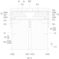
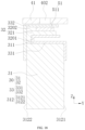
- FIG. 12 is a schematic structural cross-sectional view of a battery cell 200 according to some embodiments of this application, where the section runs through the electrolyte injection hole 402, and the section is parallel to a plane defined by the height direction and thickness direction of the body portion 31.
- the first surfaces 3201 of the tabs 32 of two electrode assemblies 30 adjacent to the electrolyte injection hole 402 may each be provided with the first protection sheet 331 to protect the corresponding tabs 32.
- the first protection sheet 331 shields the first region on the body portion 31 of the electrode assembly 30 on which the first protection sheet 331 is located.
- the first protection sheet 331 with a smaller area can be used to save materials and reduce costs, and also facilitate mounting of the first protection sheet 331 due to the reduced area of the first protection sheet 331 used.
- the first protection sheets 331 of the two electrode assemblies 30 adjacent to the electrolyte injection hole 402 extend from the body end surfaces 311 of the corresponding body portions 31 to the first side surfaces 3121 of the body portions 31, so that the two first protection sheets 331 can cooperate to shield the first regions on the two adjacent body portions 31, so as to alleviate the impact of the electrolyte being injected on the body portions 31, thus well protecting of the body portions 31.
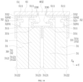
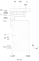
- FIG. 14 is a schematic structural cross-sectional view of a battery cell 200 according to some embodiments of this application, where the section runs through the electrolyte injection hole 402, and the section is parallel to a plane defined by the height direction and thickness direction of the body portion 31.
- the plurality of electrode assemblies 30 are divided into two groups, and the first surfaces 3201 of the tabs 32 of two electrode assemblies 30 adjacent to the electrolyte injection hole 402 are each provided with the first protection sheet 331 to shield the region corresponding to the electrolyte injection hole 402, so as to protect the body portion 31 of the electrode assembly 30.
- the second surfaces 3202 of the tabs 32 of the electrode assemblies 30 in each group may be provided with the second protection sheet 332, and the tabs 32 of same polarity of the electrode assemblies 30 in each group may be provided with one second protection sheet 332.
- the first tabs 321 of the plurality of electrode assemblies 30 in each group are connected to a same second protection sheet 332.
- the second tabs 322 of the plurality of electrode assemblies 30 in each group may also be connected to a same second protection sheet 332.
- the second protection sheet 332 protects corresponding tabs 32.
- the end cover 41 is provided with the shield plate 403, the shield plate 403 shields the electrolyte injection hole 402, and the far end 330 of the second protection sheet 332 adjacent to the electrolyte injection hole 402 is located on a side of the shield plate 403.
- the shield plate 403 extends between the far ends 330 of the two second protection sheets 332 adjacent to the electrolyte injection hole 402, so as to increase the space utilization in the housing 40 and increase the capacity density of the battery cell 200.
- FIG. 15 is a schematic structural cross-sectional view of a battery cell 200 according to some embodiments of this application, where the section runs through the electrolyte injection hole 402, and the section is parallel to a plane defined by the height direction and thickness direction of the body portion 31.
- the second surfaces 3202 of the tabs 32 of same polarity of the electrode assemblies 30 are connected a same second protection sheet 332.
- the second protection sheet 332 of the second surfaces 3202 of the tabs 32 are connected to the corresponding tabs 32 of the electrode assemblies 30, facilitating mounting of the second protection sheet 332.
- the second protection sheet 332 may extend to the electrolyte injection hole 402 to shield regions, corresponding to the electrolyte injection hole 402, on the two body portions 31 adjacent to the electrolyte injection hole 402.
- the second protection sheet 332 corresponding to one of the two tabs 32 of opposite polarities of the electrode assembly 30 may extend to the electrolyte injection hole 402 to shield the region, on the body portion 31, corresponding to the electrolyte injection hole 402.
- the electrolyte injection hole 402 is located between the two tabs 32 of opposite polarities of the electrode assembly 30, it is also possible that the second protection sheets 332 corresponding to the two tabs 32 of opposite polarities of the electrode assembly 30 both extend to the electrolyte injection hole 402 to shield the first region on the body portion 31.
- the battery cell 200 includes a plurality of electrode assemblies 30 that are divided into two groups.
- the second surfaces 3202 of the tabs 32 of same polarity of the plurality of electrode assemblies 30 are connected to a same second protection sheet 332, since the two groups of electrode assemblies 30 are stacked together to form a cell, an end of the second protection sheet 332 extends to the two electrode assemblies 30 that are at the outermost side. In this way, the end of the second protection sheet 332 extends to the second side surface 3122 of the body portion 31 of the corresponding electrode assembly 30, so as to stabilize the second protection sheet 332.
- FIG. 16 is a schematic structural cross-sectional view of a battery cell 200 according to some embodiments of this application, where the section runs through the electrolyte injection hole 402, and the section is parallel to a plane defined by the height direction and thickness direction of the body portion 31.
- first protection sheet 331 and the second protection sheet 332 can cooperate to alleviate the impact of the electrolyte being injected through the electrolyte injection hole 402 and protect the body portion 31 of the electrode assembly 30.
- first protection sheet 331 with a smaller area can be used to save materials and reduce costs, and also facilitate mounting of the first protection sheet 331.
- the second protection sheet 332 is connected to the second surfaces 3202 of the tabs 32 of same polarity corresponding to the electrode assemblies 30 to facilitate mounting of the second protection sheet 332.
- FIG. 17 is a schematic structural cross-sectional view of a battery cell 200 according to some embodiments of this application, where the section runs through the electrolyte injection hole 402, and the section is parallel to a plane defined by the height direction and thickness direction of the body portion 31.
- the battery cell 200 includes a plurality of electrode assemblies 30, and the plurality of electrode assemblies 30 are divided into two groups.
- the second surfaces 3202 of the tabs 32 of two electrode assemblies 30 adjacent to the electrolyte injection hole 402 are provided with second protection sheets 332, and the second protection sheets 332 on the two tabs 32 are of a one-piece structure.
- the second faces 3202 of the two tabs 32 are connected to a same second protection sheet 332. In this way, the second protection sheet 332 with a smaller area can be used to save materials and reduce costs.
- an end of the second protection sheet 332 extends to the second side surface 3122 of the body portion 31 adjacent to the end, so as to stabilize the second protection sheet 332.
- the battery cell 200 when the battery cell 200 includes a plurality of electrode assemblies 30, and the second surfaces 3202 of two tabs 32 adjacent to the electrolyte injection hole 402 are connected to a same second protection sheet 332, an end of the second protection sheet 332 extends to the second side surface 3122 of the body portion 31 adjacent to the end, so as to enhance the strength of the connection between the second protection sheet 332 and the corresponding body portion 31, and well protect the second surface 3202 of the tab 32.
- FIG. 18 is a schematic structural cross-sectional view of a battery cell 200 according to some embodiments of this application, where the section runs through the electrolyte injection hole 402, and the section is parallel to a plane defined by the height direction and thickness direction of the body portion 31.
- the battery cell 200 includes one electrode assembly 30, and the first surface 3201 of the tab 32 of the electrode assembly 30 is provided with a first protection sheet 331 for the first protection sheet 331 to protect the first surface 3201 of the tab 32.
- the first protection sheet 331 can be made to shield the first region on the body portion 31 for the first protection sheet 331 to buffer the electrolyte being injected through the electrolyte injection hole 402, thereby alleviating the flushing of the electrolyte to the body end surface 311 of the body portion 31 to protect the body portion 31 of the electrode assembly 30.
- the first protection sheet 331 extends from the body end surface 311 of the body portion 31 to the first side surface 3121, so as to enhance the structural strength of the connection between the first protection sheet 331 and the body portion 31, and also better protect the body end surface 311 of the body portion 31, avoiding or alleviating the flushing of the electrolyte to the body end surface 311 of the body portion 31.
- the battery cell 200 includes one electrode assembly 30, and the second surface 3202 of the tab 32 of the electrode assembly 30 is provided with a second protection sheet 332 for the second protection sheet 332 to protect the second surface 3202 of the tab 32.
- the second protection sheet 332 can be made to shield the region corresponding to the electrolyte injection hole 402 for the first protection sheet 332 to buffer the electrolyte being injected through the electrolyte injection hole 402, thereby alleviating the flushing of the electrolyte to the tab 32 and the body portion 31.
- the second protection sheet 332 extends to the second side surface 3122 to enhance the structural strength of the connection between the second protection sheet 332 and the body portion 31.
- the battery cell 200 includes one electrode assembly 30.
- the first surface 3201 of the tab 32 may be provided with a first protection sheet 331, and the second surface 3202 of the tab 32 may be provided with a second protection sheet 332 at the same time.
- the first protection sheet 331 shields the first region on the body portion 31, and the second protection sheet 332 shields the region corresponding to the electrolyte injection hole 402, so that the first protection sheet 331 and the second protection sheet 332 cooperate to buffer the electrolyte being injected through the electrolyte injection hole 402, thus enhancing buffering capability against the electrolyte being injected, so as to better protect the body portion 31 of the electrode assembly 30.
- FIG. 19 is a schematic structural cross-sectional view of a battery cell 200 according to some embodiments of this application, where the section runs through the electrolyte injection hole 402, and the section is parallel to a plane defined by the height direction and thickness direction of the body portion 31.
- the battery cell 200 includes one electrode assembly 30, and only the first surface 3201 of the tab 32 of the electrode assembly 30 is provided with a first protection sheet 331.
- the first protection sheet 331 shields the first region on the body portion 31 for the first protection sheet 331 to buffer the electrolyte being injected through the electrolyte injection hole 402, thereby alleviating the flushing of the electrolyte to the body end surface 311 of the body portion 31 to protect the body portion 31 of the electrode assembly 30.
- the first protection sheet 331 protects the first surface 3201 of the tab 32.
- only the first surface 3201 of the tab 32 being provided with the first protection sheet 331 can also save materials and reduce costs.
- FIG. 20 is a schematic structural cross-sectional view of a battery cell 200 according to some embodiments of this application, where the section runs through the electrolyte injection hole 402, and the section is parallel to a plane defined by the height direction and thickness direction of the body portion 31.
- the battery cell 200 includes one electrode assembly 30, and only the second surface 3202 of the tab 32 of the electrode assembly 30 is provided with a second protection sheet 332.
- the second protection sheet 332 shields the region corresponding to the electrolyte injection hole 402 for the second protection sheet 332 to buffer the electrolyte being injected through the electrolyte injection hole 402, thereby alleviating the flushing of the electrolyte to the tab 32 and the body portion 31.
- only the second surface 3202 of the tab 32 being provided with the second protection sheet 332 can also save materials and reduce costs.
- this application further provides a battery including the battery cell described in any one of the foregoing solutions.
- this application further provides an electric apparatus including the battery described in any one of the foregoing solutions.
- the electric apparatus may be any one of the foregoing devices or systems using a battery.
Landscapes
- Chemical & Material Sciences (AREA)
- Chemical Kinetics & Catalysis (AREA)
- Electrochemistry (AREA)
- General Chemical & Material Sciences (AREA)
- Connection Of Batteries Or Terminals (AREA)
Abstract
Description
- This application pertains to the field of battery technologies and more specifically relates to a battery cell, a battery, and an electric apparatus.
- Energy saving and emission reduction are crucial to the sustainable development of the automobile industry. Electric vehicles, with their advantages in energy conservation and environmental protection, have become an important part of sustainable development of the automobile industry. For electric vehicles, battery technology is an important factor in connection with their development.
- During manufacturing of a battery cell, after an electrode assembly is mounted in a housing body, an electrolyte needs to be injected through an electrolyte injection hole of an end cover. During injection, the electrolyte will impact the electrode assembly, resulting in damage to an electrode plate or separator, and thus causing damage to or short circuit of a cell.
- Embodiments of this application are intended to provide a battery cell, a battery, and an electric apparatus, so as to solve the problem that in the related art, during injection, an electrolyte impacts an electrode assembly, thus causing damage to an electrode plate or separator.
- According to a first aspect, an embodiment of this application provides a battery cell. The battery cell includes: an electrode assembly including a body portion and a tab, where the body portion has a body end surface, and the tab is led out of the body end surface; and a housing having a first wall, where the first wall is provided with an electrolyte injection hole and an electrode terminal, and the tab is electrically connected to the electrode terminal; where the body portion has a first region corresponding to the electrolyte injection hole, and at least one surface of the tab is provided with a protection sheet, the protection sheet shielding at least part of the first region.
- In the technical solution of this embodiment of this application, the protection sheet is provided on the tab to protect the tab, and the protection sheet is made to shield at least part of the region, on the body portion of the electrode assembly, that corresponds to the electrolyte injection hole, so that during injection of an electrolyte, impact of the electrolyte on the body portion can be alleviated so as to well protect the electrode assembly, and the risk that an electrode plate or separator of the electrode assembly is broken through during injection of the electrolyte can be reduced or prevented.
- In some embodiments, the protection sheet shields all of the first region.
- All of the first region of the body portion is shielded by the protection sheet, so that during injection of the electrolyte, the electrolyte only impacts the protection sheet and does not directly flush the body portion of the electrode assembly, so as to well protect the body portion, further reducing or preventing the risk that the electrode plate or separator of the electrode assembly is broken through during injection of the electrolyte.
- In some embodiments, the tab includes a tab root portion connected to the body portion and a tab body led out of the tab root portion, where width of the tab root portion is greater than width of the tab body, and the protection sheet is affixed to the tab root portion.
- The tab root portion is provided to be connected to the body portion, and the width of the tab root portion is set to be greater than the width of the tab body, so that the current conducting capability of the tab can be enhanced. The tab body is provided to be connected to the electrode terminal on the first wall, so as to facilitate assembly and connection. The protection sheet is affixed to the tab root portion for the tab root portion to support the protection sheet, which can enhance strength of support to the protection sheet, so as to enhance flushing resistance against the electrolyte.
- In some embodiments, a separator of the body portion exceeds the tab root portion in a direction in which the tab is led out.
- The separator of the body portion is made to exceed the tab root portion so that the tab root portion is embedded inside the separator, so as to enhance insulation and isolation, thereby reducing or preventing the risk of short circuit in the body portion.
- In some embodiments, the width of the tab root portion is greater than width of the protection sheet.
- The width of the protection sheet being set to be less than the width of the tab root portion can save materials and reduce costs; and the protection sheet with a smaller width being used also facilitates assembly and improves assembly efficiency.
- In some embodiments, the electrode assembly includes a first tab and a second tab of opposite polarities, where the first tab is made of a first conductive material, the second tab is made of a second conductive material, electrical conductivity of the first conductive material is less than electrical conductivity of the second conductive material, and the first tab has the tab root portion.
- The electrical conductivity of the first conductive material for manufacturing the first tab is smaller. Providing the tab root portion on the first tab can enhance the current flow capacity of the first tab. In addition, the first tab can be set to be thinner to reduce space occupied, which in turn increases capacity density of the battery cell.
- In some embodiments, the electrode assembly includes two tabs of opposite polarities, where the electrolyte injection hole is located between the two tabs, at least one of the tabs is provided with the protection sheet, and at least one protection sheet shields at least part of the first region.
- The electrolyte injection hole being arranged between the two tabs can facilitate the provision of the protection sheet on any of the tabs and extension of the protection sheet to the region corresponding to the electrolyte injection hole, so that during injection of the electrolyte, the flushing to the body portion of the electrode assembly by the electrolyte can be alleviated, thereby facilitating the assembly.
- In some embodiments, the tab has a first surface, the first surface being a surface of the tab facing away from the first wall; the protection sheet includes a first protection sheet affixed to the first surface, the first protection sheet shielding the first region; and the body portion has a first side surface adjacent to the body end surface; where the first protection sheet extends from the body end surface of the body portion to the first side surface.
- The first protection sheet extending from the body end surface of the body portion to the first side surface can not only enhance the structural strength of the connection between the first protection sheet and the body portion, but also better protect the body end surface of the body portion, avoiding or alleviating the flushing of the electrolyte to the body end surface of the body portion, and in particular alleviating the flushing of the electrolyte to an edge of the body end surface close to the first side surface, so as to better protect the body portion.
- In some embodiments, the first protection sheet covers the first surface of the tab.
- The first protection sheet being made to cover the first surface of the tab can better protect the tab and enhance the structural strength of the connection between the first protection sheet and the tab.
- In some embodiments, the tab has a second surface, the second surface being a surface of the tab close to the first wall; and the battery cell further includes a current collecting member connecting the second surface and the electrode terminal.
- The current collecting member is provided to connect the second surface of the tab to the electrode terminal, so as to facilitate electrical connection between the tab and the electrode terminal.
- In some embodiments, the protection sheet includes a second protection sheet disposed on the second surface, and the second surface has a connection region connected to the current collecting member, with the second protection sheet and the connection region staggered.
- The second protection sheet is provided on the second surface of the tab to protect the tab, while the second protection sheet and the connection region are made to be staggered to facilitate connection of the tab to the current collecting member for easy assembly.
- In some embodiments, the second protection sheet has an extension portion, where the extension portion extends to a position, corresponding to the connection region, on a surface of the current collecting member facing away from the tab.
- The extension portion is provided on the second protection sheet to extend to the position, of the current collecting member, corresponding to the connection region, so that the current collecting member can be protected, and the structural strength of connection of the second protection sheet can be enhanced.
- In some embodiments, the second protection sheet shields the first region.
- During injection of the electrolyte, the above structural design enables the second protection sheet to buffer the electrolyte being injected to alleviate the flushing to the body portion, thus well protecting the body portion.
- In some embodiments, the body portion has a second side surface adjacent to the body end surface; and the second protection sheet extends to the second side surface.
- The second protection sheet extending to the second side surface can enhance the structural strength of the connection between the second protection sheet and the body portion, protect the connection between the tab and the body portion, especially when the tab is disposed, on the body end surface, apart from the second side surface, and also protect a region, on the body end surface, between the tab and the second side surface to avoid or alleviate the flushing of the electrolyte to this region, thereby better protecting the body portion.
- In some embodiments, the battery cell includes a plurality of electrode assemblies, where the plurality of electrode assemblies are divided into two groups, and the tabs of two electrode assemblies adjacent to the electrolyte injection hole are each provided with the protection sheet.
- The plurality of electrode assemblies being used can increase the capacity density of the battery cell, and also facilitate processing and manufacturing of the electrode assemblies. The protection sheets being provided on the tabs of the two electrode assemblies adjacent to the electrolyte injection hole can save materials and reduce costs. In addition, because the two electrode assemblies adjacent to the electrolyte injection hole are more susceptible to the impact of the electrolyte during injection of the electrolyte, the protection sheets being provided on the tabs of the two electrode assemblies can better allow the protection sheet to shield the region corresponding to the electrolyte injection hole, so as to protect the body portion of the electrode assembly.
- In some embodiments, the protection sheets are affixed to surfaces, facing away from the first wall, of the two tabs adjacent to the electrolyte injection hole, and the protection sheet shields the first region of the electrode assembly in which the protection sheet is located.
- The protection sheets being provided on the surfaces, facing away from the first wall, of the two tabs adjacent to the electrolyte injection hole can protect the tabs, and when the protection sheets are made to shield the region corresponding to the electrolyte injection hole, the protection sheet with a smaller area can be used to save the materials of the protection sheet and reduce the costs, and also facilitate mounting of the protection sheet due to the reduced area of the protection sheet used.
- In some embodiments, the first wall is provided with a shield plate shielding the electrolyte injection hole, and an end, away from the body portion, of the protection sheet adjacent to the electrolyte injection hole is located on a side of the shield plate.
- The shield plate is provided on the first wall to shield the electrolyte injection hole, which can provide buffering during injection of the electrolyte through the electrolyte injection hole. The end, away from the body portion, of the protection sheet adjacent to the electrolyte injection hole is located on a side of the shield plate, which allows the shield plate to extend between the ends, away from the body portion, of the two adjacent protection sheets, so that not only the electrolyte being injected can be buffered by the protection sheet, but also space utilization inside the housing can be improved, the capacity density of the battery cell can be improved, and the shield plate can be prevented from bursting the protection sheet.
- In some embodiments, the protection sheets are disposed on surfaces, close to the first wall, of the tabs of the two electrode assemblies adjacent to the electrolyte injection hole.
- When a plurality of electrode assemblies are provided, during injection, the electrolyte is more likely to flush the two electrode assemblies and tabs adjacent to the electrolyte injection hole, and the protection sheets being disposed on the surfaces, close to the first wall, of the two tabs adjacent to the electrolyte injection hole can provide good protection for the two tabs adjacent to the electrolyte injection hole, alleviating the flushing of the electrolyte to the tabs, and also alleviating the flushing of the electrolyte to the body portion due to the buffering of the protection sheet on the electrolyte.
- In some embodiments, the protection sheets corresponding to the surfaces, close to the first wall, of the two tabs adjacent to the electrolyte injection hole are of a one-piece structure.
- The protection sheets corresponding to the surfaces, close to the first wall, of the two tabs adjacent to the electrolyte injection hole being arranged as a one-piece structure allows the protection sheet to shield the region corresponding to the electrolyte injection hole to alleviate the impact of the electrolyte, thereby protecting the body portion of the electrode assembly.
- In some embodiments, the protection sheets corresponding to the surfaces of the tabs close to the first wall are connected to corresponding tabs of the electrode assemblies.
- The protection sheets being connected to corresponding tabs of the electrode assemblies facilitates the mounting and fixing of the protection sheets and improves the assembly efficiency.
- In some embodiments, the body portion has a body side surface adjacent to the body end surface; and in a thickness direction of the body portion, an end of the protection sheet on the surface of the tab close to the first wall extends to the body side surface of the body portion adjacent to the end.
- The end of the protection sheet on the surface, close to the first wall, of the tab extending to the body side surface of the body portion adjacent to the end can enhance the strength of the connection between the protection sheet and the corresponding body portion, and also provide good protection for the surface of the tab close to the first wall.
- In some embodiments, the protection sheet and the tab are connected through adhesion; or the protection sheet and the tab are connected through ultrasonic welding.
- The protection sheet and the tab being connected through adhesion facilitates both connection and assembly. The protection sheet and the tab being connected through ultrasonic welding can enhance the strength of the connection between the protection sheet and the tab.
- According to a second aspect, an embodiment of this application provides a battery including the battery cell according to the foregoing embodiments.
- According to a third aspect, an embodiment of this application provides an electric apparatus including the battery according to the foregoing embodiment.
- The foregoing description is merely an overview of the technical solution of this application. For a better understanding of the technical means in this application such that they can be implemented according to the content of the specification, and to make the above and other objectives, features, and advantages of this application more obvious and easier to understand, the following describes specific embodiments of this application.
- To describe the technical solutions in the embodiments of this application more clearly, the following briefly describes the accompanying drawings required for describing the embodiments or exemplary art. Apparently, the accompanying drawings in the following description show merely some embodiments of this application, and persons of ordinary skill in the art may still derive other drawings from these accompanying drawings without creative efforts.
-
FIG. 1 is a schematic structural diagram of a vehicle according to some embodiments of this application; -
FIG. 2 is a schematic structural exploded view of a battery according to some embodiments of this application; -
FIG. 3 is a schematic structural exploded view of a battery cell according to some embodiments of this application; -
FIG. 4 is a schematic structural diagram of an end cover and an electrode assembly in the battery cell inFIG. 3 ; -
FIG. 5 is a schematic structural diagram of an unfolded electrode assembly in the battery cell inFIG. 3 ; -
FIG. 6 is a schematic three-dimensional structural diagram of the electrode assembly inFIG. 5 ; -
FIG. 7 is a schematic structural diagram of a connection between a tab and a current collecting member of the electrode assembly inFIG. 6 ; -
FIG. 8 is a schematic structural cross-sectional view of a battery cell according to some embodiments of this application; -
FIG. 9 is a schematic structural diagram of a portion of the electrode assembly inFIG. 8 ; -
FIG. 10 is a schematic structural cross-sectional view of a battery cell according to some embodiments of this application; -
FIG. 11 is a schematic structural diagram of a portion of the electrode assembly inFIG. 10 ; -
FIG. 12 is a schematic structural cross-sectional view of a battery cell according to some embodiments of this application; -
FIG. 13 is a schematic structural cross-sectional view of a battery cell according to some embodiments of this application; -
FIG. 14 is a schematic structural cross-sectional view of a battery cell according to some other embodiments of this application; -
FIG. 15 is a schematic structural cross-sectional view of a battery cell according to still some other embodiments of this application; -
FIG. 16 is a schematic structural cross-sectional view of a battery cell according to some embodiments of this application; -
FIG. 17 is a schematic structural cross-sectional view of a battery cell according to some other embodiments of this application; -
FIG. 18 is a schematic structural cross-sectional view of a battery cell according to some embodiments of this application; -
FIG. 19 is a schematic structural cross-sectional view of a battery cell according to some other embodiments of this application; and -
FIG. 20 is a schematic structural cross-sectional view of a battery cell according to still some other embodiments of this application. - Major reference signs in the figures:
- 1000. vehicle; 1001. battery; 1002. controller; 1003. motor;
- 100. box; 101. first part; 102. second part;
- 200. battery cell;
- 30. electrode assembly; 31. body portion; 311. body end surface; 312. body side surface; 3121. first side surface; 3122. second side surface; 32. tab; 3201. first surface; 3202. second surface; 3203. connection region; 321. first tab; 322. second tab; 3231. tab body; 3232. tab root portion; 33. protection sheet; 330. far end; 331. first protection sheet; 332. second protection sheet; 3321. extension portion; 34. insulating sheet;
- 40. housing; 401. first wall; 402. electrolyte injection hole; 403. shield plate; 41. end cover; 42. housing body; 43. electrode terminal; 431. first terminal; 432. second terminal;
- 51. current collecting member; 511. first current collecting member; 512. second current collecting member;
- 52. supporting plate;
- X. width direction; Y. thickness direction; and Z. height direction.
- To make the technical problems to be solved, technical solutions, and beneficial effects of this application more comprehensible, the following describes this application in detail with reference to accompanying drawings and embodiments. It should be understood that the specific embodiments described herein are merely used to explain this application but are not intended to limit this application.
- Unless otherwise defined, all technical and scientific terms used herein shall have the same meanings as commonly understood by those skilled in the art to which this application relates. The terms used herein are intended to merely describe the specific embodiments rather than to limit this application. The terms "include", "include", and "have" and any other variations thereof in the specification, claims and brief description of drawings of this application are intended to cover non-exclusive inclusions.
- In the description of the embodiments of this application, the terms "first", "second", and the like are merely intended to distinguish between different objects, and shall not be understood as any indication or implication of relative importance or any implicit indication of the number, sequence or primary-secondary relationship of the technical features indicated. Therefore, a feature limited by "first" or "second" may explicitly or implicitly include one or more features.
- In this specification, reference to "embodiment" means that specific features, structures or characteristics described with reference to the embodiment may be incorporated in at least one embodiment of this application. The word "embodiment" appearing in various places in the specification does not necessarily refer to the same embodiment or an independent or alternative embodiment that is exclusive of other embodiments. Persons skilled in the art explicitly and implicitly understand that the embodiments described herein may combine with another embodiment in any suitable manner.
- In the description of the embodiments of this application, the term "and/or" is only an associative relationship for describing associated objects, indicating that three relationships may be present. For example, A and/or B may indicate the following three cases: presence of only A, presence of both A and B, and presence of only B. In addition, the character "/" in this specification generally indicates an "or" relationship between contextually associated objects.
- In the description of the embodiments of this application, the term "a plurality of" means more than two (inclusive). Similarly, "a plurality of groups" means more than two (inclusive) groups, and "a plurality of pieces" means more than two (inclusive) pieces. "Several" means one or more unless otherwise specifically stated.
- In the description of the embodiments of this application, the orientations or positional relationships indicated by the technical terms "center", "longitudinal" "transverse", "length", "width", "thickness", "upper", "lower", "front", "rear", "left", "right", "vertical", "horizontal", "top", "bottom", "inside", "outside", "clockwise", "counterclockwise", "axial", "radial", "circumferential", and the like are based on the orientations or positional relationships as shown in the accompanying drawings. These terms are merely for ease and brevity of the description of the embodiments of this application rather than indicating or implying that the means or components mentioned must have specific orientations, or must be constructed or manipulated according to specific orientations, and therefore shall not be construed as any limitations on embodiments of this application.
- In the description of the embodiments of this application, unless otherwise specified and defined explicitly, the terms "mount", "connect", "join", and "fasten" should be understood in their general senses. For example, they may refer to a fixed connection, a detachable connection, or an integral connection, may refer to a mechanical connection or an electrical connection, and may refer to a direct connection, an indirect connection via an intermediate medium, an internal communication between two elements, or an interaction between two elements. Persons of ordinary skill in the art can understand specific meanings of these terms in this application as appropriate to specific situations.
- In the description of the embodiments of this application, unless otherwise expressly specified and limited, when a component is referred to as being "fastened to" or "disposed on" another component, it may be directly on the another component, or may be indirectly on the another component. When a component is referred to as being "connected to" another component, it may be directly connected to the another component, or may be indirectly connected to the another component.
- In the description of the embodiments of this application, unless otherwise expressly specified and limited, the technical term "adjacent" means being positionally close. For example, when there are three components A1, A2, and B, if the distance between A1 and B is greater than the distance between A2 and B, then A2 is closer to B compared to A1. In other words, A2 is adjacent to B, and it can also be said that B is adjacent to A2. For another example, when there are a plurality of components C, and the plurality of components C are denoted as C1, C2, ..., and CN, if one of the components C, such as C2, is closer to component B compared to other components C, then B is adjacent to C2, and it can also be said that C2 is adjacent to B.
- In this application, the battery cell may include a lithium-ion secondary battery, a lithium-ion primary battery, a lithium-sulfur battery, a sodium-lithium-ion battery, a sodium-ion battery, a magnesium-ion battery, or the like. This is not limited in the embodiments of this application. The battery cell may be cylindrical, flat, cuboid, or of other shapes, which is not limited in the embodiments of this application either. Battery cells are typically divided into three types by packaging method: cylindrical cell, prismatic cell, and pouch cell. The type of battery is not limited in the embodiments of this application either.
- The battery mentioned in the embodiments of this application is a single physical module that includes one or more battery cells for providing a higher voltage and capacity. For example, the battery mentioned in this application may include a battery module, a battery pack, or the like. A battery typically includes a box configured to enclose one or more battery cells. The box can prevent liquids or other foreign matter from affecting charging or discharging of the battery cell. In some cases, the battery cell may also be used directly, that is, the battery may also not include a box, which is not limited herein.
- If a plurality of battery cells are provided in a battery, the plurality of battery cells may be connected in series, parallel, or series-parallel, where being connected in series-parallel means a combination of series and parallel connections of the plurality of battery cells. The plurality of battery cells may be directly connected in series, parallel, or series-parallel, and then an entirety constituted by the plurality of battery cells is accommodated in the box. Certainly, the battery may be formed by a plurality of battery cells connected in series, parallel, or series-parallel first to form a battery module and then a plurality of battery modules being connected in series, parallel, or series-parallel to form an entirety which is accommodated in the box. The battery may further include other structures. For example, the battery may further include a busbar configured to implement electrical connection between the plurality of battery cells.
- The battery cell in the embodiments of this application includes an electrode assembly and a housing. The electrode assembly is also referred to as a bare battery cell. The electrode assembly includes a positive electrode plate, a negative electrode plate, and a separator. The electrode assembly mainly relies on migration of metal ions between the positive electrode plate and the negative electrode plate. The positive electrode plate includes a positive electrode current collector and a positive electrode active substance layer. The positive electrode active substance layer is applied on a surface of the positive electrode current collector. The part of the positive electrode current collector not coated with the positive electrode active substance layer protrudes out of the part of the positive electrode current collector coated with the positive electrode active substance layer. The part not coated with the positive electrode active substance layer serves as a positive electrode tab or a metal conductor is welded to and led out of the positive electrode current collector to serve as the positive electrode tab. A lithium-ion battery is used as an example, for which, the positive electrode current collector may be made of aluminum, and the positive electrode active substance may be lithium cobaltate, lithium iron phosphate, ternary lithium, lithium manganate, or the like. The negative electrode plate includes a negative electrode current collector and a negative electrode active substance layer. The negative electrode active substance layer is applied on a surface of the negative electrode current collector. The part of the negative electrode current collector not coated with the negative electrode active substance layer protrudes out of the part of the negative electrode current collector coated with the negative electrode active substance layer. The part not coated with the negative electrode active substance layer serves as a negative electrode tab or a metal conductor is welded to and led out of the negative electrode current collector to serve as the negative electrode tab. The negative electrode current collector may be made of copper, and the negative electrode active substance may be carbon, silicon, or the like. To allow a large current to pass through without any fusing, a plurality of positive electrode tabs can be led out of the positive electrode plate and be stacked together to form an entire positive electrode tab; and similarly, a plurality of negative electrode tabs can be led out of the negative electrode plate and be stacked together to form an entire negative electrode tab. It can be understood that in the electrode assembly, a positive electrode tab can be led out of the positive electrode plate and a negative electrode tab can be led out of the negative electrode plate. Both the positive and negative electrode tabs are referred to as tabs. In other words, the electrode assembly is provided with two tabs of opposite polarities, one is the positive electrode tab and the other is the negative electrode tab. Accordingly, the electrode assembly includes a body portion and the tabs. The positive electrode plate, the negative electrode plate, and the separator are stacked and wound to form the body portion of the electrode assembly, and the tabs are led out of the body portion.
- The electrode assembly may be a wound structure or a stacked structure. The embodiments of this application are not limited thereto. In a wound structure, the tabs are typically welded onto the current collector and then the parts are arranged in a sequence of positive electrode plate - separator - negative electrode plate - separator and then wound to form a cylindrical or prismatic cell. In a stacked structure, the electrode tabs are typically led out of the current collector, and the positive electrode plate, the negative electrode plate, and the separator are arranged in a sequence of positive electrode plate - separator - negative electrode plate - separator and then stacked together layer by layer to form a stacked battery cell, where the separator can be cut and directly stacked as separator plates, or the separator can be folded in a Z-shape without being cut. The separator may be made of PP (polypropylene, polypropylene), PE (polyethylene, polyethylene), or the like. The separator is an insulating film disposed between the positive electrode plate and the negative electrode plate. A main function of the separator is to separate the positive and negative electrodes and prevent the electrons in the battery from passing freely to avoid a short circuit, while allowing ions in an electrolyte to freely pass between the positive and negative electrodes to form a circuit between the positive and negative electrodes. The positive electrode plate and the negative electrode plate are collectively referred to as electrode plates. The positive electrode tab and negative electrode tab are collectively referred to as tabs.
- A housing is a shell structure with an accommodating space inside. The electrode assembly is placed in the accommodating space of the housing for the housing to house and protect the electrode assembly.
- After the electrode assembly is manufactured, the electrode assembly needs to be mounted in the housing, and an electrolyte is injected to immerse the electrode assembly in the electrolyte so that the electrode assembly can fully absorb the electrolyte. However, during injection of the electrolyte, a certain impact force is present, so that when impacting the body portion of the electrode assembly, the electrolyte impacts the separator and the electrode plates of the body portion, which may cause folding of the separator and thus exposure of the electrode plate, leading to self-discharge due to lapping of the tab to a body end surface of the electrode plate. This may even cause damage to the electrode plate or separator, which consumes electrical energy and even cause the risk of short circuit in the battery, affecting performance and service life of the battery.
- Based on the above considerations, to solve the problem that during injection of the electrolyte, the electrolyte flushes the electrode assembly and causes folding of the separator or even breakage of the electrode plate or separator, the embodiments of this application provide a battery cell. A protection sheet provided on a tab extends to a region corresponding to an electrolyte injection hole to at least partially shields the region, corresponding to the electrolyte injection hole, on a body portion of an electrode assembly. In this way, during injection of the electrolyte, the protection sheet can buffer and disperse the electrolyte being injected, so as to alleviate the impact of the electrolyte on the body portion and well protect the electrode assembly, which in turn avoids folding of the separator due to flushing of the electrolyte, reduce or prevent the risk that an electrode plate or separator of the electrode assembly is broken through during injection of the electrolyte, and improve the performance and service life of a battery.
- The battery cell disclosed in the embodiments of this application may be used for electric apparatuses that use a battery as a power source or various energy storage systems that use a battery as an energy storage element, such as an energy storage power system applied to a hydroelectric, thermal, wind, and solar power plant. The electric apparatus may be but is not limited to a mobile phone, a tablet computer, a laptop computer, an electric toy, an electric tool, an electric bicycle, an electric motorcycle, an electric car, a ship, or a spacecraft. The electric toy may be a fixed or mobile electric toy, for example, a game console, an electric toy car, an electric toy ship, and an electric toy airplane. The spacecraft may include an airplane, a rocket, a space shuttle, a spaceship, and the like.
- For ease of description, the electric apparatus provided in an embodiment of this application being a vehicle is used as an example for description.
- Referring to
FIG. 1, FIG. 1 is a schematic structural diagram of avehicle 1000 according to some embodiments of this application. Thevehicle 1000 may be a fossil fuel vehicle, a natural-gas vehicle, or a new energy vehicle. The new energy vehicle may be a battery electric vehicle, a hybrid electric vehicle, a range-extended electric vehicle, or the like. Thevehicle 1000 is provided with abattery 1001 inside, and thebattery 1001 may be disposed at the bottom, front, or rear of thevehicle 1000. Thebattery 1001 may be configured to supply power to thevehicle 1000. For example, thebattery 1001 may be used as an operational power source for thevehicle 1000. Thevehicle 1000 may further include acontroller 1002 and amotor 1003, where thecontroller 1002 is configured to control thebattery 1001 to supply power to themotor 1003, for example, to satisfy power needs of start, navigation, and driving of thevehicle 1000. - In some embodiments of this application, the
battery 1001 can be used as not only the operational power source for thevehicle 1000 but also a driving power source for thevehicle 1000, replacing or partially replacing fossil fuel or natural gas to provide driving traction for thevehicle 1000. - Referring to
FIG. 2, FIG. 2 is a schematic structural exploded view of abattery 1001 according to some embodiments of this application. Thebattery 1001 includes abox 100 and abattery cell 200, where thebattery cell 200 is accommodated in thebox 100. Thebox 100 is configured to provide an accommodating space for thebattery cell 200. Thebox 100 may be a variety of structures. In some embodiments, thebox 100 may include afirst part 101 and asecond part 102. Thefirst part 101 and thesecond part 102 fit together so that thefirst part 101 and thesecond part 102 jointly define a space for accommodating thebattery cell 200. Thesecond part 102 may be a hollow structure with one end open, and thefirst part 101 may be a plate structure, where thefirst part 101 covers the open side of thesecond part 102 for thefirst part 101 and thesecond part 102 to jointly define an accommodating space; or alternatively, thefirst part 101 and thesecond part 102 may both be hollow structures with one side open, where the open side of thefirst part 101 is engaged with the open side of thesecond part 102. Certainly, thebox 100 formed by thefirst part 101 and thesecond part 102 may have a variety of shapes, for example, cylinder or cuboid. A plurality of battery cells are connected in parallel, series, or series-parallel, and then put into thebox 100 formed after thefirst par 101 and thesecond part 102 are snap-fitted. - Referring to
FIG. 3, FIG. 3 is a schematic structural exploded view of abattery cell 200 according to some embodiments of this application. Referring toFIGs. 4 to 7 ,FIG. 4 is a schematic structural diagram of anend cover 41 separated from anelectrode assembly 30 in abattery cell 200 according to some embodiments of this application;FIG. 5 is a schematic structural diagram of an unfoldedelectrode assembly 30 in abattery cell 200 according to some embodiments of this application;FIG. 6 is a schematic three-dimensional structural diagram of anelectrode assembly 30 in abattery cell 200 according to some embodiments of this application; andFIG. 7 is a schematic structural diagram of a connection between atab 32 and a current collectingmember 51 of anelectrode assembly 30 in abattery cell 200 according to some embodiments of this application - The
battery cell 200 includes ahousing 40 and anelectrode assembly 30. Theelectrode assembly 30 is mounted in thehousing 40 for thehousing 40 to accommodate and protect theelectrode assembly 30. After theelectrode assembly 30 is mounted in thehousing 40, an electrolyte is further added to thehousing 40 to allow theelectrode assembly 30 to absorb the electrolyte. - The
electrode assembly 30 includes abody portion 31 and atab 32, with thetab 32 led out of thebody portion 31. - The
housing 40 has a first wall 401, the first wall 401 being a side wall of thehousing 40. The first wall 401 is provided with anelectrolyte injection hole 402 for injecting the electrolyte into thehousing 40 through theelectrolyte injection hole 402. The first wall 401 is provided with anelectrode terminal 43, where the first wall 401 supports theelectrode terminal 43, and theelectrode terminal 43 is electrically connected to thetab 32. - For ease of description, a region, on the
body portion 31, corresponding to theelectrolyte injection hole 402 is defined as a first region, and during injection of the electrolyte, the electrolyte enters thehousing 40 through theelectrolyte injection hole 402, and the electrolyte impacts the first region on thebody portion 31. To be specific, a region that is on thebody portion 31 of theelectrode assembly 30 mounted in thehousing 40 and corresponds to theelectrolyte injection hole 402 is the first region; that is, during injection of the electrolyte, a region, on thebody portion 31, that the electrolyte directly flushes is the first region. - At least one surface of the
tab 32 is provided with aprotection sheet 33, and theprotection sheet 33 shields at least part of the region, on thebody portion 31, corresponding to theelectrolyte injection hole 402. In other words, the region, on thebody portion 31, corresponding to theelectrolyte injection hole 402 is at least partially shielded by theprotection sheet 33, that is, theprotection sheet 33 shields the first region on thebody portion 31, so that during injection of the electrolyte through theelectrolyte injection hole 402, theprotection sheet 33 can buffer the electrolyte to alleviate the impact of the electrolyte on thebody portion 31, so as to avoid folding of the separator due to the flushing of the electrolyte, thus reducing or preventing the risk that an electrode plate or separator of theelectrode assembly 30 is broken through during injection of the electrolyte, and improving performance and service life of a battery. In these embodiments of this application, theprotection sheet 33 is provided on thetab 32 to protect thetab 32, and theprotection sheet 33 is made to shield at least part of the region, on thebody portion 31 of theelectrode assembly 30, that corresponds to theelectrolyte injection hole 402, so that during injection of the electrolyte, impact of the electrolyte on thebody portion 31 can be alleviated so as to well protect theelectrode assembly 30, and the risk that the electrode plate or separator of theelectrode assembly 30 is broken through during injection of the electrolyte can be reduced or prevented. - The
protection sheet 33 is a sheet structure provided on thetab 32 to protect thetab 32. In some embodiments, theprotection sheet 33 may be an insulating film for providing good insulation and protection. Theprotection sheet 33 may be made of a material such as PP (Polypropylene, polypropylene), PE (Polyethylene, polyethylene), PET (polyethylene glycol terephthalate, polyethylene glycol terephthalate), or the like. - The
electrode terminal 43 refers to a conductive member provided on the first wall 401 of thehousing 40. Theelectrode terminal 43 is connected to thetab 32 of theelectrode assembly 30 to output electrical energy of thebattery cell 200 or to charge thebattery cell 200. Theelectrode terminal 43 of thebattery cell 200 is typically provided in a quantity of two, and the twoelectrode terminals 43 are connected to the positive andnegative electrode tabs 32 of theelectrode assembly 30 respectively. Theelectrode terminal 43 connected to thepositive electrode tab 32 is thepositive electrode terminal 43, and theelectrode terminal 43 connected to thenegative electrode tab 32 is thenegative electrode terminal 43. Theelectrode assembly 30 is connected to theelectrode terminal 43 on theend cover 41 to form thebattery cell 200, and certainly, thebattery cell 200 may include other functional components. - In some embodiments, the two
tabs 32 of opposite polarities of theelectrode assembly 30 may be afirst tab 321 and asecond tab 322 respectively, where thefirst tab 321 may be thepositive electrode tab 32 and thesecond tab 322 may be thenegative electrode tab 32. Certainly, thefirst tab 321 may be thenegative electrode tab 32 and thesecond tab 322 may be thepositive electrode tab 32. Accordingly, theelectrode terminal 43 is also provided in a quantity of two. Theelectrode terminal 43 connected to thefirst tab 321 may be referred to as afirst terminal 431, and theelectrode terminal 43 connected to thesecond tab 322 may be referred to as asecond terminal 432. - As shown in
FIG. 3 , theelectrode assembly 30 has a height direction, a width direction, and a thickness direction. In the figure, the direction Z is the height direction of theelectrode assembly 30; the direction X is the width direction of theelectrode assembly 30; and the direction Y is the thickness direction of theelectrode assembly 30. The height direction of theelectrode assembly 30 is also a height direction of thebody portion 31 thereof; the width direction of theelectrode assembly 30 is also a width direction of thebody portion 31 thereof; and the thickness direction of theelectrode assembly 30 is also a thickness direction of thebody portion 31 thereof. - The
battery cell 200 may include one ormore electrode assemblies 30. When thebattery cell 200 includes a plurality ofelectrode assemblies 30, the plurality ofelectrode assemblies 30 are divided into two groups, each group including at least oneelectrode assembly 30. For example, when theelectrode assemblies 30 are provided in a quantity of two, the twoelectrode assemblies 30 are divided into two groups. However, when the quantity of theelectrode assemblies 30 is greater than two, at least one group includes at least twoelectrode assemblies 30, while the other group includes at least oneelectrode assembly 30. When the quantity ofelectrode assemblies 30 is an even number, the quantity ofelectrode assemblies 30 in the two groups may be set to be the same. - Referring to
FIGs. 3 to 6 , for ease of description, it is defined that: the surface of thebody portion 31 of theelectrode assembly 30 on which thetab 32 is led out is defined as abody end surface 311 of thebody portion 31. In this way, thebody portion 31 has thebody end surface 311, and thetab 32 is led out of thefirst end surface 311. In other words, thetab 32 is connected to thebody portion 31 through thebody end surface 311 of thebody portion 31. Thebody end surface 311 of thebody portion 31 is a surface at an end of thebody portion 31 in the height direction (that is, the direction Z). - For ease of description, it is defined that: the
body portion 31 of theelectrode assembly 30 has abody side surface 312, where thebody side surface 312 is a surface on thebody portion 31 adjacent to thebody end surface 311. Thebody side surface 312 of thebody portion 31 includes oppositefirst side surface 3121 andsecond side surface 3122, where thefirst side surface 3121 and thesecond side surface 3122 are both surfaces defined by the height direction (that is, the direction Z) and width direction (that is, the direction X) of thebody portion 31. Therefore it can be learned that the normal direction of thefirst side surface 3121 and thesecond side surface 3122 is the thickness direction (that is, the direction Y) of thebody portion 31, that is, distance between thefirst side surface 3121 and thesecond side surface 3122 is thickness of thebody portion 31. - For ease of description, it is defined that: opposite surfaces of the
tab 32 are thefirst surface 3201 and thesecond surface 3202. When thetab 32 is flattened along the height direction (that is, the direction Z) of thebody portion 31, the thickness direction of thebody portion 31 is also the thickness direction of thetab 32, thefirst surface 3201 of thetab 32 and thefirst side surface 3121 of thebody portion 31 are located on a same side of thetab 32 in the thickness direction, and thesecond surface 3202 of thetab 32 and thesecond side surface 3122 of thebody portion 31 are located on a same side of thetab 32 in the thickness direction. - Since the
tab 32 is typically connected to theelectrode terminal 43 on the first wall 401 before assembly, and then thetab 32 is bent for theelectrode assembly 30 to be mounted in thehousing 40, as for the manufacturedbattery cell 200, thefirst surface 3201 of thetab 32 is a surface of thetab 32 facing away from the first wall 401, and thesecond surface 3202 of thetab 32 is a surface of thetab 32 close to the first wall 401. - In some embodiments, referring to
FIGs. 3 and7 , thebattery cell 200 further includes a current collectingmember 51. The current collectingmember 51 is a conductive member connecting thetab 32 and theelectrode terminal 43. The current collectingmember 51 may be a structure such as a conductive sheet or a conductive adapter sheet. The current collectingmember 51 connects thetab 32 and theelectrode terminal 43 to facilitate the connection between thetab 32 and theelectrode terminal 43, enabling a more stable connection. It can be understood that in some cases, thetab 32 may also be directly connected to theelectrode terminal 43. - The
electrode assembly 30 typically includes twotabs 32 of opposite polarities, and theelectrode terminal 43 is also provided in a quantity of two. Accordingly, the current collectingmember 51 is typically provided in a quantity of two. The twocurrent collecting members 51 correspond to the twoelectrode terminals 43 respectively. Each current collectingmember 51 is connected to the correspondingelectrode terminal 43, and each current collectingmember 51 is connected to the correspondingtab 32. In other words, eachtab 32 is connected to the correspondingelectrode terminal 43 through the current collectingmember 51 to facilitate the connection between thetab 32 and theelectrode terminal 43, enabling a more stable connection. For ease of description, the current collectingmember 51 connected to thefirst terminal 431 is referred to as the first current collectingmember 511, and thefirst tab 321 is connected to the first current collectingmember 511; and the current collectingmember 51 connected to thesecond terminal 432 is referred to as the second current collectingmember 512, and thesecond tab 322 is connected to the second current collectingmember 512. - In the following description of embodiments, unless otherwise specified, the term "tab" may refer to the
first tab 321, thesecond tab 322, or both thefirst tab 321 and thesecond tab 322; the term "electrode terminal" may refer to thefirst terminal 431, thesecond terminal 432, or both thefirst terminal 431 and thesecond terminal 432; and the term "current collecting member" may refer to the first current collectingmember 511, the second current collectingmember 512, or both the first current collectingmember 511 and the second current collectingmember 512. - In some embodiments, referring to
FIG. 3 , thehousing 40 includes ahousing body 42 and anend cover 41, where theend cover 41 covers thehousing body 42 to form thehousing 40 structure. Theelectrode assembly 30 is mounted in thehousing body 42, and theend cover 41 covers thehousing body 42 so that theelectrode assembly 30 is mounted in thehousing 40. - The
end cover 41 is a component that covers an opening of thehousing body 42 to isolate an internal environment of thebattery cell 200 from an external environment. A shape of theend cover 41 may be adapted to a shape of thehousing body 42 to fit and cover thehousing body 42. Optionally, theend cover 41 may be made of a material with certain hardness and strength (for example, aluminum alloy), so that theend cover 41 is less likely to deform when subjected to extrusion and collision, allowing thebattery cell 200 to have higher structural strength and enhanced safety performance. Theend cover 41 may also be made of various materials, such as copper, iron, aluminum, stainless steel, aluminum alloy, and plastic, which are not particularly limited in the embodiments of this application. - The
housing body 42 is an assembly configured to fit with theend cover 41 to form the internal environment of thebattery cell 200, where the formed internal environment may be configured to accommodate theelectrode assembly 30, an electrolyte, and other components. Thehousing body 42 and theend cover 41 may be separate components, an opening may be provided on thehousing body 42, and theend cover 41 covers the opening to form the internal environment of thebattery cell 200. Thehousing body 42 may be of various shapes and sizes, such as a cuboid shape, a cylindrical shape, and a hexagonal prism shape. Specifically, the shape of thehousing body 42 may be determined according to a specific shape and size of thebattery cell 200. Thehousing body 42 may be made of various materials, such as copper, iron, aluminum, stainless steel, aluminum alloy, and plastic, which are not particularly limited in the embodiments of this application. - In some embodiments, the
end cover 41 may further be provided with a pressure relief mechanism for releasing internal pressure when the internal pressure or a temperature of thebattery cell 200 reaches a threshold. - In some embodiments, the
battery cell 200 further includes a supportingplate 52, where the supportingplate 52 is mounted in thehousing body 42 and can support the bottom of thebody portion 31 of theelectrode assembly 30, increasing the structural strength of thebattery cell 200. - In some embodiments, referring to
FIGs. 3 to 5 , theend cover 41 is provided with anelectrolyte injection hole 402 and anelectrode terminal 43. In other words, theend cover 41 is the first wall 401 of thehousing 40. This facilitates the processing of theelectrolyte injection hole 402 and the mounting of theelectrode terminal 43 on thehousing 40. It should be understood that one of the other side walls of thehousing 40 may also be used as the first wall 401, for example, the bottom of thehousing body 42 of thehousing 40 may be used as the first wall 401, and theelectrolyte injection hole 402 and theelectrode terminal 43 are mounted on the bottom of thehousing body 42. - The end cover 41 being used as the first wall 401 of the
housing 40 involves a relatively simple manufacturing process, and this facilitates the mounting of theelectrode terminal 43, as well as the connection between thetab 32 theelectrode terminal 43. Therefore, the following embodiments will provide detailed description with theend cover 41 used as the first wall 401 of thehousing 40 as an example. When theend cover 41 is used as the first wall 401 of thehousing 40, theelectrolyte injection hole 402 is provided on theend cover 41, theelectrode terminal 43 is mounted on theend cover 41, the surface of thetab 32 facing away from theend cover 41 is thefirst surface 3201, and the surface of thetab 32 close to theend cover 41 is thesecond surface 3202. - In some embodiments, referring to
FIGs. 3 to 5 , theprotection sheet 33 shields all of the region, on thebody portion 31, corresponding to theelectrolyte injection hole 402. To be specific, all of the first region of thebody portion 31 is shielded by theprotection sheet 33, so that during injection of the electrolyte, the electrolyte only impacts theprotection sheet 33 and does not directly flush thebody portion 31 of theelectrode assembly 30, so as to well protect thebody portion 31, further reducing or preventing the risk that the electrode plate or separator of theelectrode assembly 30 is broken through during injection of the electrolyte. - It can be understood that the
protection sheet 33 may alternatively shield only part of the first region, so that theprotection sheet 33 can provide certain blocking and buffering on the electrolyte being injected through theelectrolyte injection hole 402, and can also reduce the impact of the electrolyte on thebody portion 31 of theelectrode assembly 30, so as to protect thebody portion 31. - In some embodiments, referring to
FIGs. 3 to 6 , thetab 32 includes atab root portion 3232 and atab body 3231, where thetab body 3231 is connected to thetab root portion 3232, thetab root portion 3232 is connected to thebody portion 31, and thetab body 3231 is led out of thetab root portion 3232. Thetab body 3231 is electrically connected to theelectrode terminal 43 during use. Width of thetab root portion 3232 is greater than width of thetab body 3231, which can enhance the current conducting capability of thetab 32, allowing forthinner tab 32 and reducing space occupied. In addition, this can also enhance the structural strength at the connection between thetab root portion 3232 and thebody portion 31. In other words, this enhances the structural strength of thebody end surface 311 where thetab 32 is led out of thebody portion 31. Thetab body 3231 is provided for ease of connection to thefirst electrode terminal 43 on the first wall 401, facilitating assembly and connection. - In some embodiments, the
protection sheet 33 is affixed to thetab root portion 3232 for thetab root portion 3232 to support theprotection sheet 33, which can enhance the strength of support to theprotection sheet 33, so as to enhance the flushing resistance against the electrolyte. - In some embodiments, referring to
FIGs. 3 to 6 , the separator of thebody portion 31 exceeds thetab root portion 3232 in a direction in which thetab 32 is led out. As shown in the figure, in the height direction of thebody portion 31, the separator exceeds thetab root portion 3232 so that thetab root portion 3232 is embedded inside the separator, so as to enhance insulation and isolation, thereby reducing or preventing the risk of short circuit in thebody portion 31. In particular, if a plurality oftabs 32 are led out of thebody portion 31 and thesetabs 32 are stacked to form anentire tab 32, when the plurality oftab root portions 3232 are bent and stacked toward one side, the risk of short circuit of thebody portion 31 can be better reduced or avoided, thus improving safety. - In some embodiments, referring to
FIGs. 3 to 6 , the width of thetab root portion 3232 being set to be greater than the width of theprotection sheet 33 can save materials and reduce costs; and theprotection sheet 33 with a smaller width being used also facilitates assembly and improves assembly efficiency. - In some embodiments, referring to
FIGs. 3 to 6 , thefirst tab 321 is made of a first conductive material, thesecond tab 322 is made of a second conductive material, electrical conductivity of the first conductive material is less than electrical conductivity of the second conductive material, and thefirst tab 321 has thetab root portion 3232. The electrical conductivity of the first conductive material for manufacturing thefirst tab 321 is smaller. Thus, thefirst tab 321 including thetab root portion 3232 enables the current flow capacity of thefirst tab 321 to be enhanced. In addition, thefirst tab 321 can be set to be thinner to reduce space occupied, which in turn increases capacity density of thebattery cell 200. - It can be understood that the
second tab 322 may also be provided with thetab root portion 3232 to enhance the current flow capacity of thesecond tab 322, so that when current flow performance (that is, the performance for current flow) of thesecond tab 322 reaches a set requirement, thesecond tab 322 can be set to be thinner to reduce the space occupied, which in turn increases the capacity density of thebattery cell 200. - In some embodiments, the
first tab 321 is apositive tab 32, that is, thepositive tab 32 has thetab root portion 3232 for improving the current flow performance of thepositive tab 32. - In some embodiments, the
first tab 321 may be provided with aprotection sheet 33 to protect thefirst tab 321. Similarly, thesecond tab 322 may be provided with aprotection sheet 33 to protect thesecond tab 322. - In some embodiments, the
electrolyte injection hole 402 is located between twotabs 32 of opposite polarities. To be specific, theelectrolyte injection hole 402 is located between thefirst tab 321 and thesecond tab 322, such that theprotection sheet 33 can be provided on thefirst tab 321 and theprotection sheet 33 shields at least part of the first region on thebody portion 31. In addition, it is also possible to provide aprotection sheet 33 on thesecond tab 322 and have theprotection sheet 33 on thesecond tab 322 extend to the region corresponding to theelectrolyte injection hole 402. In addition, it is also possible to provide theprotection sheet 33 on both thefirst tab 321 and thesecond tab 322, and have any one of theprotection sheets 33 extend to the region corresponding to theelectrolyte injection hole 402. Certainly, it is also possible to have theprotection sheets 33 on both thefirst tab 321 and thesecond tab 322 extend to the region corresponding to theelectrolyte injection hole 402 to cooperate in buffering the electrolyte being injected through theelectrolyte injection hole 402. In other words, theelectrolyte injection hole 402 being arranged between the twotabs 32 of opposite polarities can facilitate the provision of theprotection sheet 33 on any of thetabs 32 and extension of theprotection sheet 33 to the region corresponding to theelectrolyte injection hole 402, so that during injection of the electrolyte, the flushing to thebody portion 31 of theelectrode assembly 30 by the electrolyte can be alleviated, thereby facilitating the assembly. - It can be understood that the
electrolyte injection hole 402 may alternatively be located on a side of thefirst tab 321 away from thesecond tab 322, so that theprotection sheet 33 on thefirst tab 321 can extend to the region corresponding to theelectrolyte injection hole 402 for theprotection sheet 33 on thefirst tab 321 to buffer the electrolyte being injected through theelectrolyte injection hole 402. Certainly, theelectrolyte injection hole 402 may alternatively be located on a side of thesecond tab 322 away from thefirst tab 321, so that theprotection sheet 33 on thesecond tab 322 can extend to the region corresponding to theelectrolyte injection hole 402 for theprotection sheet 33 on thesecond tab 322 to buffer the electrolyte being injected through theelectrolyte injection hole 402. - In some embodiments, referring to
FIGs. 3 to 6 , theprotection sheet 33 and thetab 32 may be connected through adhesion. Theprotection sheet 33 and thetab 32 being connected through adhesion facilitates both connection and assembly. It can be understood that theprotection sheet 33 and thetab 32 are connected through ultrasonic welding. Theprotection sheet 33 and thetab 32 being connected through ultrasonic welding can enhance the strength of the connection between theprotection sheet 33 and thetab 32. - In some embodiments, width D1 of the
protection sheet 33 on thefirst tab 321 is greater than 40 mm, for example, the width D1 of theprotection sheet 33 on thefirst tab 321 may be set to 40 mm, 41 mm, 42 mm, 43 mm, 44 mm, 45 mm, 46 mm, 47 mm, 48 mm, 49 mm, 50 mm, 51 mm, 52 mm, 53 mm, 54 mm, 55 mm, 56 mm, 57 mm, 58 mm, 59 mm, 60 mm, or the like, so as to guarantee the width of theprotection sheet 33, facilitating extension of theprotection sheet 33 to the region corresponding to theelectrolyte injection hole 402. A width D1 direction of theprotection sheet 33 is consistent with the width direction of thebody portion 31. - In some embodiments, width D2 of the
protection sheet 33 on thesecond tab 322 is greater than 40 mm, for example, the width D2 of theprotection sheet 33 on thesecond tab 322 may be set to 40 mm, 41 mm, 42 mm, 43 mm, 44 mm, 45 mm, 46 mm, 47 mm, 48 mm, 49 mm, 50 mm, 51 mm, 52 mm, 53 mm, 54 mm, 55 mm, 56 mm, 57 mm, 58 mm, 59 mm, 60 mm, or the like, so as to guarantee the width of theprotection sheet 33, facilitating extension of theprotection sheet 33 to the region corresponding to theelectrolyte injection hole 402. A width D2 direction of theprotection sheet 33 is consistent with the width direction of thebody portion 31. - In some embodiments, referring to
FIGs. 3 to 6 , theprotection sheet 33 includes afirst protection sheet 331, where thefirst protection sheet 331 is affixed to thefirst surface 3201 of thetab 32. In other words, theprotection sheet 33 affixed to thefirst surface 3201 of thetab 32 is thefirst protection sheet 331, and thefirst protection sheet 331 protects thetab 32. - In some embodiments, the
first protection sheet 331 shields the first region on thebody portion 31 for thefirst protection sheet 331 to buffer the electrolyte being injected through theelectrolyte injection hole 402, thereby alleviating the flushing of the electrolyte to thebody end surface 311 of thebody portion 31 to protect thebody portion 31 of theelectrode assembly 30. - In some embodiments, the
first protection sheet 331 extends from thebody end surface 311 of thebody portion 31 to thefirst side surface 3121, which can not only enhance the structural strength of the connection between thefirst protection sheet 331 and thebody portion 31, but also better protect thebody end surface 311 of thebody portion 31, avoiding or alleviating the flushing of the electrolyte to thebody end surface 311 of thebody portion 31. Thefirst protection sheet 331 extends from thebody end surface 311 of thebody portion 31 to thefirst side surface 3121 to protect the connection between thebody end surface 311 and thefirst side 3121, so as to alleviate the flushing of the electrolyte to an edge of thebody end surface 311 close to thefirst side surface 3121, thus better protecting thebody portion 31. - In some embodiments, the
first protection sheet 331 may be affixed to thetab root portion 3232 of thefirst tab 321 to enhance the strength of support to thefirst protection sheet 331 through thetab root portion 3232, thereby enhancing the flushing resistance of thefirst protection sheet 331 against the electrolyte. - In some embodiments, referring to
FIGs. 3 to 6 , thefirst protection sheet 331 covers thefirst surface 3201 of thetab 32. Thefirst protection sheet 331 being made to cover thefirst surface 3201 of thetab 32 can better protect thetab 32 and enhance the structural strength of the connection between thefirst protection sheet 331 and thetab 32. - In some embodiments, referring to
FIGs. 3 ,6 , and7 , if thebattery cell 200 includes the current collectingmember 51, when the current collectingmember 51 connects thetab 32 and the correspondingelectrode terminal 43, the current collectingmember 51 may be connected to thesecond surface 3202 of thetab 32, facilitating electrical connection between thetab 32 and theelectrode terminal 43. - In some embodiments, referring to
FIG. 3 , theelectrode assembly 30 further includes an insulatingsheet 34, the insulatingsheet 34 wrapping around thebody portion 31 to bind thebody portion 31 of theelectrode assembly 30 and well protect thebody portion 31. - In some embodiments, the
battery cell 200 includes twoelectrode assemblies 30, where the insulatingsheet 34 wraps around thebody portions 31 of the twoelectrode assemblies 30 to bind thebody portions 31 of the twoelectrode assemblies 30. This facilitates installation and can provide good protection for thebody portions 31 of the twoelectrode assemblies 30. It can be understood that the insulatingsheet 34 can be wrapped around each of thebody portions 31 separately. Certainly, when thebattery cell 200 includes a greater quantity ofelectrode assemblies 30, thebody portions 31 of the plurality ofelectrode assemblies 30 may be wrapped together to facilitate assembly. - In some embodiments, the
battery cell 200 includes twoelectrode assemblies 30, where the twoelectrode assemblies 30 are divided into two groups, with each group having one electrode assembly. When thebattery cells 200 are provided in a greater quantity, the electrode assemblies may also be divided into two groups, with each group having one ormore electrode assemblies 30. A plurality ofelectrode assemblies 30 being used can increase the capacity density of thebattery cell 200, and also facilitates the processing and manufacturing of theelectrode assemblies 30. - In some embodiments, the
battery cell 200 includes twoelectrode assemblies 30, where thetabs 32 of the twoelectrode assemblies 30 are each provided with aprotection sheet 33, and in particular, the twotabs 32 adjacent to theelectrolyte injection hole 402 are provided with theprotection sheets 33 so that theprotection sheets 33 can extend to the region corresponding to theelectrolyte injection hole 402. If the twofirst tabs 321 adjacent to theelectrolyte injection hole 402 are provided with theprotection sheets 33, each of theprotection sheets 33 can extend to a region, on acorresponding body portion 31, corresponding to theelectrolyte injection hole 402 to protect thecorresponding body portion 31, and theprotection sheets 33 on the twofirst tabs 321 adjacent to theelectrolyte injection hole 402 can be made to cooperate to shield the first regions on thebody portions 31. - In some embodiments, the
battery cell 200 includes twoelectrode assemblies 30, and during injection of the electrolyte, the electrolyte impacts the positions on the twoelectrode assemblies 30 adjacent to theelectrolyte injection hole 402. Theprotection sheets 33 are provided on thetabs 32, of the twoelectrode assemblies 30, adjacent to theelectrolyte injection hole 402, so that theprotection sheets 33 can be made to better shield the region corresponding to theelectrolyte injection hole 402, that is, theprotection sheets 33 are made to better shield the first regions on thebody portions 31, so as to protect thebody portions 31 of theelectrode assemblies 30. For example, thefirst tabs 321 of the twoelectrode assemblies 30 of thebattery cell 200 are disposed adjacent to theelectrolyte injection hole 402, thefirst tabs 321 are provided with theprotection sheets 33, and theprotection sheets 33 are made to shield the first regions on thecorresponding body portions 31, so as to protect thebody portions 31 andfirst tabs 321 of theelectrode assemblies 30. It can be understood that when thesecond tab 322 of theelectrode assembly 30 is disposed adjacent to theelectrolyte injection hole 402, thesecond tab 322 may also be provided with theprotection sheet 33 such that theprotection sheet 33 on thesecond tab 322 shields the first region. - In some embodiments, the
first surfaces 3201 of the twotabs 32 adjacent to theelectrolyte injection hole 402 are affixed with theprotection sheets 33, and theprotection sheets 33 shield regions that are on thebody portions 31 of theelectrode assemblies 30 in which theprotection sheets 33 are located and correspond to theelectrolyte injection hole 402. In other words, theprotection sheets 33 are made to shield the first regions on thebody portions 31 of theelectrode assemblies 30 in which theprotection sheets 33 are located. For example, thefirst tabs 321 of the twoelectrode assemblies 30 of thebattery cell 200 are disposed adjacent to theelectrolyte injection hole 402, and thefirst surfaces 3201 of thefirst tabs 321 are affixed with thefirst protection sheets 331 for thefirst protection sheets 331 to protect thefirst tabs 321 and buffer the electrolyte being injected through theelectrolyte injection hole 402, so as to protect thebody portions 31 of theelectrode assemblies 30. - In some embodiments, the
protection sheets 33 may be separately provided on thetabs 32 of theelectrode assemblies 30, and area of eachprotection sheet 33 may be made to be smaller, conducive to saving materials and reducing costs, and theprotection sheet 33 with smaller area being used also facilitates mounting of theprotection sheet 33. For example, thefirst protection sheets 331 are affixed to thefirst tabs 321 of the twoelectrode assemblies 30 respectively, so that the area of eachfirst protection sheet 331 can be set to be smaller to save materials and facilitate assembly. - In some embodiments, referring to
FIGs. 3 to 6 , the first wall 401 of thehousing 40 is provided with ashield plate 403. When theend cover 41 serves as the first wall 401, theend cover 41 is provided with theshield plate 403, and theshield plate 403 shields theelectrolyte injection hole 402, which can buffer the electrolyte being injected through theelectrolyte injection hole 402, so as to alleviate the impact force of the electrolyte during injection of the electrolyte. - For ease of description, an end of the
protection sheet 33 away from thebody portion 31 is defined as afar end 330. - In some embodiments, referring to
FIGs. 3 to 6 , thefar end 330 of theprotection sheet 33 adjacent to theelectrolyte injection hole 402 is located on a side of theshield plate 403. To be specific, the far ends 330 of the twoprotection sheets 33 adjacent to theelectrolyte injection hole 402 are apart from each other, and theshield plate 403 is located between the far ends 330 of the twoprotection sheets 33 adjacent to theelectrolyte injection hole 402, so that theprotection sheet 33 can buffer the electrolyte being injected through theelectrolyte injection hole 402, and space utilization in thehousing 40 can also be increased, so as to increase the capacity density of thebattery cell 200. In addition, such structure can prevent theprotection sheet 33 from being elongated to break when two groups ofelectrode assemblies 30 are brought close to form a cell, and can also prevent theshield plate 403 from bursting theprotection sheet 33. - In some embodiments, referring to
FIGs. 3 to 5 , when thetab 32 is provided with thefirst protection sheet 331, the far ends 330 of the twofirst protection sheets 331 adjacent to theelectrolyte injection hole 402 are located on the sides of theshield plate 403 to reduce the space occupied, improving the space utilization in thehousing 40, and thereby increasing the capacity density of thebattery cell 200. In addition, for such structure, thefar end 330 of thefirst protection sheet 331 is located on the side of theshield plate 403 and the shield edge does not burst thefirst protection sheet 331, ensuring good connection between thefirst protection sheet 331 and thefirst tab 321 due, and guaranteeing the structural strength of the connection. - Referring to
FIGs. 8 and9 ,FIG. 8 is a schematic structural cross-sectional view of abattery cell 200 according to some embodiments of this application, where the section runs through theelectrolyte injection hole 402, and the section is parallel to a plane defined by the height direction and thickness direction of thebody portion 31.FIG. 9 is a schematic structural diagram of a portion of anelectrode assembly 30 in abattery cell 200 according to some embodiments of this application. - In some embodiments, the
protection sheet 33 includes asecond protection sheet 332, where thesecond protection sheet 332 is affixed to thesecond surface 3202 of thetab 32. In other words, theprotection sheet 33 affixed to thesecond surface 3202 of thetab 32 is thesecond protection sheet 332, and thesecond protection sheet 332 protects thetab 32. - In the description of these embodiments, unless otherwise specified, the term "protection sheet" may refer to the
first protection sheet 331, thesecond protection sheet 332, or both thefirst protection sheet 331 and thesecond protection sheet 332. Thefirst protection sheet 331 is aprotection sheet 33 disposed on thefirst surface 3201 of thetab 32, and thesecond protection sheet 332 is aprotection sheet 33 disposed on thesecond surface 3202 of thetab 32. - In some embodiments, the
second surface 3202 of thetab 32 is connected to the current collectingmember 51, and thesecond surface 3202 of thetab 32 has aconnection region 3203, theconnection region 3203 being a region connected to the current collectingmember 51. Thesecond protection sheet 332 and theconnection region 3203 are staggered to prevent thesecond protection sheet 332 from interfering with the connection between thetab 32 and the current collectingmember 51. - In some embodiments, the
second protection sheet 332 has anextension portion 3321, where theextension portion 3321 extends to a position, corresponding to theconnection region 3203, on a surface of the current collectingmember 51 facing away from thetab 32. Theextension portion 3321 is provided on thesecond protection sheet 332 to extend to the position, of the current collectingmember 51, corresponding to theconnection region 3203, so that the current collectingmember 51 can be protected, and the structural strength of connection of thesecond protection sheet 332 can be enhanced. In addition, theextension portion 3321 is provided on thesecond protection sheet 332, so that after thetab 32 is connected to the current collectingmember 51, anentire protection sheet 33 can be used to affix to the current collectingmember 51 and thesecond surface 3202 of thetab 32 for easy assembly. - In some embodiments, referring to
FIGs. 8 and9 , thefirst protection sheet 331 and thesecond protection sheet 332 may be respectively provided on two surfaces of onetab 32 for thefirst protection sheet 331 and thesecond protection sheet 332 to cooperate and protect thetab 32. - In some embodiments, the
second protection sheet 332 can be made to shield the first region on thebody portion 31, so that during injection of the electrolyte, thesecond protection sheet 332 can buffer the electrolyte being injected to alleviate the flushing to thebody portion 31, thus well protecting thebody portion 31. - In some embodiments, the
second protection sheet 332 extending to thesecond side surface 3122 can enhance the structural strength of the connection between thesecond protection sheet 332 and thebody portion 31, and can protect the connection between thetab 32 and thebody portion 31. In addition, when thetab 32 is led out of a middle region on thebody end surface 311 of thebody portion 31 in the thickness direction of thebody portion 31, that is, when thetab 32 is apart from thesecond side surface 3122, thesecond protection sheet 332 also shields the region, on thebody end surface 311 of thebody portion 31, between thetab 32 and thesecond side surface 3122 to protect the region, on thebody end surface 311, between thetab 32 and thesecond side surface 3122, thereby avoiding or alleviating the flushing of the electrolyte to this region, so as to better protect thebody portion 31. - In some embodiments, the
battery cell 200 includes twoelectrode assemblies 30, theend cover 41 is provided with theshield plate 403, theshield plate 403 shields theelectrolyte injection hole 402, and thefar end 330 of thesecond protection sheet 332 adjacent to theelectrolyte injection hole 402 is located on a side of theshield plate 403. To be specific, the far ends 330 of the twosecond protection sheets 332 adjacent to theelectrolyte injection hole 402 are apart from each other, and theshield plate 403 is located between the far ends 330 of the twosecond protection sheets 332 adjacent to theelectrolyte injection hole 402, so as to increase the space utilization in thehousing 40 and increase the capacity density of thebattery cell 200. In addition, such structure can prevent thesecond protection sheet 332 from being elongated to break when two groups ofelectrode assemblies 30 are brought close to form a cell, and can also prevent theshield plate 403 from bursting thesecond protection sheet 332. - In some embodiments, when the
second protection sheet 332 has great strength, it is also possible to press thefar end 330 of thesecond protection sheet 332 against thebody end surface 311 of thebody portion 31 using theshield plate 403, or affix thefar end 330 of thesecond protection sheet 332 to thebody portion 31, so as to stably support thesecond protection sheet 332. - Referring to
FIGs. 10 and11 ,FIG. 10 is a schematic structural cross-sectional view of abattery cell 200 according to some embodiments of this application, where the section runs through theelectrolyte injection hole 402, and the section is parallel to a plane defined by the height direction and thickness direction of thebody portion 31.FIG. 11 is a schematic structural diagram of a portion of anelectrode assembly 30 in abattery cell 200 according to some embodiments of this application. - In some embodiments, the
battery cell 200 includes twoelectrode assemblies 30, and thesecond protection sheets 332 on thefirst tabs 321 of the twoelectrode assemblies 30 are of a one-piece structure. For example, anentire protection sheet 33 can be used to connect the twofirst tabs 321. Certainly, thesecond protection sheets 332 on the twofirst tabs 321 can be connected to facilitate mounting of thesecond protection sheet 332 on thefirst tab 321. - In some embodiments, the
battery cell 200 includes twoelectrode assemblies 30, and thesecond protection sheets 332 on thesecond tabs 322 of the twoelectrode assemblies 30 are of a one-piece structure. For example, anentire protection sheet 33 can be used to connect the twosecond tabs 322. Certainly, thesecond protection sheets 332 on the twosecond tabs 322 can be connected to facilitate mounting of thesecond protection sheet 332 on thesecond tab 322. - In some embodiments, the
battery cell 200 includes twoelectrode assemblies 30, and the twosecond protection tabs 332 adjacent to theelectrolyte injection hole 402 are connected to form a one-piece structure, so that thesecond protection sheets 332 can be made to shield the region corresponding to theelectrolyte injection hole 402. To be specific, thesecond protection tabs 332 are made to shield the first regions to alleviate the impact of the electrolyte, so as to protect thebody portion 31 of theelectrode assembly 30. - In some embodiments, when the
second protection sheets 332 of the twotabs 32 adjacent to theelectrolyte injection hole 402 are of a one-piece structure, and the twotabs 32 adjacent to theelectrolyte injection hole 402 are provided with thefirst protection sheets 331, thefirst protection sheets 331 and thesecond protection sheets 332 can cooperate to buffer the impact of the electrolyte being injected, so as to better protect thebody portions 31 of the twoelectrode assemblies 30. - Referring to
FIG 12, FIG. 12 is a schematic structural cross-sectional view of abattery cell 200 according to some embodiments of this application, where the section runs through theelectrolyte injection hole 402, and the section is parallel to a plane defined by the height direction and thickness direction of thebody portion 31. - In some embodiments, the
battery cell 200 includes twoelectrode assemblies 30, and thesecond protection sheet 332 may be provided only on thetabs 32 of the twoelectrode assemblies 30. The twosecond protection sheets 332 of the twotabs 32 adjacent to theelectrolyte injection hole 402 are arranged as a one-piece structure to cover the regions, on thebody portion 31, corresponding to theelectrolyte injection hole 402. To be specific, thesecond protection tabs 332 are made to shield the first regions to alleviate the impact of the electrolyte, so as to protect thebody portions 31 of theelectrode assemblies 30. - Referring to
FIG 13, FIG. 13 is a schematic structural cross-sectional view of abattery cell 200 according to some embodiments of this application, where the section runs through theelectrolyte injection hole 402, and the section is parallel to a plane defined by the height direction and thickness direction of thebody portion 31. - In some embodiments, the
battery cell 200 includes a plurality ofelectrode assemblies 30, where the plurality ofelectrode assemblies 30 are divided into two groups. For example, when thebattery cell 200 includes fourelectrode assemblies 30, each group may include twoelectrode assemblies 30. Certainly, when twobattery cells 200 are provided and divided into two groups, each group may include oneelectrode assembly 30. When threebattery cells 200 are provided and divided into two groups, one group may include oneelectrode assembly 30, and the other group includes twoelectrode assemblies 30. In other words, when thebattery cell 200 includes a plurality ofelectrode assemblies 30, where the plurality ofelectrode assemblies 30 are divided into two groups, each group may include one ormore electrode assemblies 30. A plurality ofelectrode assemblies 30 being used can increase the capacity density of thebattery cell 200, and also facilitates the processing and manufacturing of theelectrode assemblies 30. - In some embodiments, when the
battery cell 200 includes a plurality ofelectrode assemblies 30, thetabs 32 of twoelectrode assemblies 30 adjacent to theelectrolyte injection hole 402 are each provided with theprotection sheet 33. Theprotection sheets 33 being provided on thetabs 32 of the twoelectrode assemblies 30 adjacent to theelectrolyte injection hole 402 can save materials and reduce costs. In addition, because the twoelectrode assemblies 30 adjacent to theelectrolyte injection hole 402 are more susceptible to the impact of the electrolyte during injection of the electrolyte, theprotection sheets 33 being provided on thetabs 32 of the twoelectrode assemblies 30 can better allow theprotection sheet 33 to shield the region corresponding to theelectrolyte injection hole 402, so as to protect thebody portions 31 of theelectrode assemblies 30. - In some embodiments, when the
battery cell 200 includes a plurality ofelectrode assemblies 30, thefirst surfaces 3201 of thetabs 32 of twoelectrode assemblies 30 adjacent to theelectrolyte injection hole 402 may each be provided with thefirst protection sheet 331 to protect thecorresponding tabs 32. Thefirst protection sheet 331 shields the first region on thebody portion 31 of theelectrode assembly 30 on which thefirst protection sheet 331 is located. When thefirst protection sheet 331 is used to shield the region corresponding to theelectrolyte injection hole 402, thefirst protection sheet 331 with a smaller area can be used to save materials and reduce costs, and also facilitate mounting of thefirst protection sheet 331 due to the reduced area of thefirst protection sheet 331 used. - In some embodiments, the
first protection sheets 331 of the twoelectrode assemblies 30 adjacent to theelectrolyte injection hole 402 extend from the body end surfaces 311 of thecorresponding body portions 31 to thefirst side surfaces 3121 of thebody portions 31, so that the twofirst protection sheets 331 can cooperate to shield the first regions on the twoadjacent body portions 31, so as to alleviate the impact of the electrolyte being injected on thebody portions 31, thus well protecting of thebody portions 31. - Referring to
FIG 14, FIG. 14 is a schematic structural cross-sectional view of abattery cell 200 according to some embodiments of this application, where the section runs through theelectrolyte injection hole 402, and the section is parallel to a plane defined by the height direction and thickness direction of thebody portion 31. - In some embodiments, when the
battery cell 200 includes a plurality ofelectrode assemblies 30, the plurality ofelectrode assemblies 30 are divided into two groups, and thefirst surfaces 3201 of thetabs 32 of twoelectrode assemblies 30 adjacent to theelectrolyte injection hole 402 are each provided with thefirst protection sheet 331 to shield the region corresponding to theelectrolyte injection hole 402, so as to protect thebody portion 31 of theelectrode assembly 30. - In some embodiments, the
second surfaces 3202 of thetabs 32 of theelectrode assemblies 30 in each group may be provided with thesecond protection sheet 332, and thetabs 32 of same polarity of theelectrode assemblies 30 in each group may be provided with onesecond protection sheet 332. For example, thefirst tabs 321 of the plurality ofelectrode assemblies 30 in each group are connected to a samesecond protection sheet 332. Certainly, thesecond tabs 322 of the plurality ofelectrode assemblies 30 in each group may also be connected to a samesecond protection sheet 332. Thesecond protection sheet 332 protects correspondingtabs 32. - In some embodiments, the
end cover 41 is provided with theshield plate 403, theshield plate 403 shields theelectrolyte injection hole 402, and thefar end 330 of thesecond protection sheet 332 adjacent to theelectrolyte injection hole 402 is located on a side of theshield plate 403. In this way, theshield plate 403 extends between the far ends 330 of the twosecond protection sheets 332 adjacent to theelectrolyte injection hole 402, so as to increase the space utilization in thehousing 40 and increase the capacity density of thebattery cell 200. - Referring to
FIG 15, FIG. 15 is a schematic structural cross-sectional view of abattery cell 200 according to some embodiments of this application, where the section runs through theelectrolyte injection hole 402, and the section is parallel to a plane defined by the height direction and thickness direction of thebody portion 31. - In some embodiments, when the
battery cell 200 includes a plurality ofelectrode assemblies 30, thesecond surfaces 3202 of thetabs 32 of same polarity of theelectrode assemblies 30 are connected a samesecond protection sheet 332. To be specific, thesecond protection sheet 332 of thesecond surfaces 3202 of thetabs 32 are connected to thecorresponding tabs 32 of theelectrode assemblies 30, facilitating mounting of thesecond protection sheet 332. - In some embodiments, the
second protection sheet 332 may extend to theelectrolyte injection hole 402 to shield regions, corresponding to theelectrolyte injection hole 402, on the twobody portions 31 adjacent to theelectrolyte injection hole 402. For example, thesecond protection sheet 332 corresponding to one of the twotabs 32 of opposite polarities of theelectrode assembly 30 may extend to theelectrolyte injection hole 402 to shield the region, on thebody portion 31, corresponding to theelectrolyte injection hole 402. Certainly, when theelectrolyte injection hole 402 is located between the twotabs 32 of opposite polarities of theelectrode assembly 30, it is also possible that thesecond protection sheets 332 corresponding to the twotabs 32 of opposite polarities of theelectrode assembly 30 both extend to theelectrolyte injection hole 402 to shield the first region on thebody portion 31. - In some embodiments, the
second protection sheet 332 extends to theelectrolyte injection hole 402 to shield the first region on thebody portion 31, and thesecond protection sheet 332 is connected to thetabs 32 of same polarity. In this way, thesecond protection sheet 332 can be better supported, and the impact resistance of thesecond protection sheet 332 can be improved, thus batter alleviating the impact of the electrolyte being injected through theelectrolyte injection hole 402, so as to protect thebody portion 31 of theelectrode assembly 30. - In some embodiments, the
battery cell 200 includes a plurality ofelectrode assemblies 30 that are divided into two groups. When thesecond surfaces 3202 of thetabs 32 of same polarity of the plurality ofelectrode assemblies 30 are connected to a samesecond protection sheet 332, since the two groups ofelectrode assemblies 30 are stacked together to form a cell, an end of thesecond protection sheet 332 extends to the twoelectrode assemblies 30 that are at the outermost side. In this way, the end of thesecond protection sheet 332 extends to thesecond side surface 3122 of thebody portion 31 of the correspondingelectrode assembly 30, so as to stabilize thesecond protection sheet 332. - Referring to
FIG 16, FIG. 16 is a schematic structural cross-sectional view of abattery cell 200 according to some embodiments of this application, where the section runs through theelectrolyte injection hole 402, and the section is parallel to a plane defined by the height direction and thickness direction of thebody portion 31. - In some embodiments, when the
battery cell 200 includes a plurality ofelectrode assemblies 30, thefirst surfaces 3201 of thetabs 32 of twoelectrode assemblies 30 adjacent to theelectrolyte injection hole 402 are each provided with thefirst protection sheet 331, and thefirst protection sheet 331 shields the first region on thebody portion 31 of theelectrode assembly 30 on which thefirst protection sheet 331 is located. Thesecond surfaces 3202 of thetabs 32 of same polarity of theelectrode assemblies 30 are connected to a samesecond protection sheet 332, and thesecond protection sheet 332 extends to theelectrolyte injection hole 402 to shield the first regions on the twobody portions 31 adjacent to theelectrolyte injection hole 402. In this way, thefirst protection sheet 331 and thesecond protection sheet 332 can cooperate to alleviate the impact of the electrolyte being injected through theelectrolyte injection hole 402 and protect thebody portion 31 of theelectrode assembly 30. In addition, thefirst protection sheet 331 with a smaller area can be used to save materials and reduce costs, and also facilitate mounting of thefirst protection sheet 331. Thesecond protection sheet 332 is connected to thesecond surfaces 3202 of thetabs 32 of same polarity corresponding to theelectrode assemblies 30 to facilitate mounting of thesecond protection sheet 332. - Referring to
FIG 17, FIG. 17 is a schematic structural cross-sectional view of abattery cell 200 according to some embodiments of this application, where the section runs through theelectrolyte injection hole 402, and the section is parallel to a plane defined by the height direction and thickness direction of thebody portion 31. - In some embodiments, the
battery cell 200 includes a plurality ofelectrode assemblies 30, and the plurality ofelectrode assemblies 30 are divided into two groups. Thesecond surfaces 3202 of thetabs 32 of twoelectrode assemblies 30 adjacent to theelectrolyte injection hole 402 are provided withsecond protection sheets 332, and thesecond protection sheets 332 on the twotabs 32 are of a one-piece structure. In other words, the second faces 3202 of the twotabs 32 are connected to a samesecond protection sheet 332. In this way, thesecond protection sheet 332 with a smaller area can be used to save materials and reduce costs. - In some embodiments, an end of the
second protection sheet 332 extends to thesecond side surface 3122 of thebody portion 31 adjacent to the end, so as to stabilize thesecond protection sheet 332. - In some embodiments, as shown in
FIGs. 16 and17 , when thebattery cell 200 includes a plurality ofelectrode assemblies 30, and thesecond surfaces 3202 of twotabs 32 adjacent to theelectrolyte injection hole 402 are connected to a samesecond protection sheet 332, an end of thesecond protection sheet 332 extends to thesecond side surface 3122 of thebody portion 31 adjacent to the end, so as to enhance the strength of the connection between thesecond protection sheet 332 and thecorresponding body portion 31, and well protect thesecond surface 3202 of thetab 32. - Referring to
FIG 18, FIG. 18 is a schematic structural cross-sectional view of abattery cell 200 according to some embodiments of this application, where the section runs through theelectrolyte injection hole 402, and the section is parallel to a plane defined by the height direction and thickness direction of thebody portion 31. - In some embodiments, the
battery cell 200 includes oneelectrode assembly 30, and thefirst surface 3201 of thetab 32 of theelectrode assembly 30 is provided with afirst protection sheet 331 for thefirst protection sheet 331 to protect thefirst surface 3201 of thetab 32. Thefirst protection sheet 331 can be made to shield the first region on thebody portion 31 for thefirst protection sheet 331 to buffer the electrolyte being injected through theelectrolyte injection hole 402, thereby alleviating the flushing of the electrolyte to thebody end surface 311 of thebody portion 31 to protect thebody portion 31 of theelectrode assembly 30. - In some embodiments, the
first protection sheet 331 extends from thebody end surface 311 of thebody portion 31 to thefirst side surface 3121, so as to enhance the structural strength of the connection between thefirst protection sheet 331 and thebody portion 31, and also better protect thebody end surface 311 of thebody portion 31, avoiding or alleviating the flushing of the electrolyte to thebody end surface 311 of thebody portion 31. - In some embodiments, the
battery cell 200 includes oneelectrode assembly 30, and thesecond surface 3202 of thetab 32 of theelectrode assembly 30 is provided with asecond protection sheet 332 for thesecond protection sheet 332 to protect thesecond surface 3202 of thetab 32. Thesecond protection sheet 332 can be made to shield the region corresponding to theelectrolyte injection hole 402 for thefirst protection sheet 332 to buffer the electrolyte being injected through theelectrolyte injection hole 402, thereby alleviating the flushing of the electrolyte to thetab 32 and thebody portion 31. - In some embodiments, the
second protection sheet 332 extends to thesecond side surface 3122 to enhance the structural strength of the connection between thesecond protection sheet 332 and thebody portion 31. - In some embodiments, the
battery cell 200 includes oneelectrode assembly 30. Thefirst surface 3201 of thetab 32 may be provided with afirst protection sheet 331, and thesecond surface 3202 of thetab 32 may be provided with asecond protection sheet 332 at the same time. Thefirst protection sheet 331 shields the first region on thebody portion 31, and thesecond protection sheet 332 shields the region corresponding to theelectrolyte injection hole 402, so that thefirst protection sheet 331 and thesecond protection sheet 332 cooperate to buffer the electrolyte being injected through theelectrolyte injection hole 402, thus enhancing buffering capability against the electrolyte being injected, so as to better protect thebody portion 31 of theelectrode assembly 30. - Referring to
FIG 19, FIG. 19 is a schematic structural cross-sectional view of abattery cell 200 according to some embodiments of this application, where the section runs through theelectrolyte injection hole 402, and the section is parallel to a plane defined by the height direction and thickness direction of thebody portion 31. - In some embodiments, the
battery cell 200 includes oneelectrode assembly 30, and only thefirst surface 3201 of thetab 32 of theelectrode assembly 30 is provided with afirst protection sheet 331. Thefirst protection sheet 331 shields the first region on thebody portion 31 for thefirst protection sheet 331 to buffer the electrolyte being injected through theelectrolyte injection hole 402, thereby alleviating the flushing of the electrolyte to thebody end surface 311 of thebody portion 31 to protect thebody portion 31 of theelectrode assembly 30. Moreover, thefirst protection sheet 331 protects thefirst surface 3201 of thetab 32. In addition, only thefirst surface 3201 of thetab 32 being provided with thefirst protection sheet 331 can also save materials and reduce costs. - Referring to
FIG 20, FIG. 20 is a schematic structural cross-sectional view of abattery cell 200 according to some embodiments of this application, where the section runs through theelectrolyte injection hole 402, and the section is parallel to a plane defined by the height direction and thickness direction of thebody portion 31. - In some embodiments, the
battery cell 200 includes oneelectrode assembly 30, and only thesecond surface 3202 of thetab 32 of theelectrode assembly 30 is provided with asecond protection sheet 332. Thesecond protection sheet 332 shields the region corresponding to theelectrolyte injection hole 402 for thesecond protection sheet 332 to buffer the electrolyte being injected through theelectrolyte injection hole 402, thereby alleviating the flushing of the electrolyte to thetab 32 and thebody portion 31. In addition, only thesecond surface 3202 of thetab 32 being provided with thesecond protection sheet 332 can also save materials and reduce costs. - According to some embodiments of this application, this application further provides a battery including the battery cell described in any one of the foregoing solutions.
- According to some embodiments of this application, this application further provides an electric apparatus including the battery described in any one of the foregoing solutions.
- The electric apparatus may be any one of the foregoing devices or systems using a battery.
- In conclusion, it should be noted that the foregoing embodiments are for description of the technical solutions of this application only rather than for limiting this application. Although this application has been described in detail with reference to the foregoing embodiments, persons of ordinary skill in the art should appreciate that they can still make modifications to the technical solutions described in the embodiments or make equivalent replacements to some or all technical features thereof without departing from the scope of the technical solutions of the embodiments of this application. All such modifications and equivalent replacements shall fall within the scope of claims and specification of this application. In particular, as long as there is no structural conflict, the various technical features mentioned in the embodiments can be combined in any manner. This application is not limited to the specific embodiments disclosed in this specification, but includes all technical solutions falling within the scope of the claims.
Claims (24)
- A battery cell, characterized by comprising:an electrode assembly comprising a body portion and a tab, wherein the body portion has a body end surface, and the tab is led out of the body end surface; anda housing having a first wall, wherein the first wall is provided with an electrolyte injection hole and an electrode terminal, and the tab is electrically connected to the electrode terminal; whereinthe body portion has a first region corresponding to the electrolyte injection hole, and at least one surface of the tab is provided with a protection sheet, the protection sheet shielding at least part of the first region.
- The battery cell according to claim 1, characterized in that the protection sheet shields all of the first region.
- The battery cell according to claim 1 or 2, characterized in that the tab comprises a tab root portion connected to the body portion and a tab body led out of the tab root portion, wherein width of the tab root portion is greater than width of the tab body, and the protection sheet is affixed to the tab root portion.
- The battery cell according to claim 3, characterized in that a separator of the body portion exceeds the tab root portion in a direction in which the tab is led out.
- The battery cell according to claim 3 or 4, characterized in that the width of the tab root portion is greater than width of the protection sheet.
- The battery cell according to any one of claims 3 to 5, characterized in that the electrode assembly comprises a first tab and a second tab of opposite polarities, wherein the first tab is made of a first conductive material, the second tab is made of a second conductive material, electrical conductivity of the first conductive material is less than electrical conductivity of the second conductive material, and the first tab has the tab root portion.
- The battery cell according to any one of claims 1 to 6, characterized in that the electrode assembly comprises two tabs of opposite polarities, wherein the electrolyte injection hole is located between the two tabs, at least one of the tabs is provided with the protection sheet, and at least one protection sheet shields at least part of the first region.
- The battery cell according to any one of claims 1 to 7, characterized in that the tab has a first surface, the first surface being a surface of the tab facing away from the first wall; the protection sheet comprises a first protection sheet affixed to the first surface, the first protection sheet shielding the first region; and the body portion has a first side surface adjacent to the body end surface; wherein the first protection sheet extends from the body end surface of the body portion to the first side surface.
- The battery cell according to claim 8, characterized in that the first protection sheet covers the first surface of the tab.
- The battery cell according to any one of claims 1 to 9, characterized in that the tab has a second surface, the second surface being a surface of the tab close to the first wall; and the battery cell further comprises a current collecting member connecting the second surface and the electrode terminal.
- The battery cell according to claim 10, characterized in that the protection sheet comprises a second protection sheet disposed on the second surface, and the second surface has a connection region connected to the current collecting member, with the second protection sheet and the connection region staggered.
- The battery cell according to claim 11, characterized in that the second protection sheet has an extension portion, wherein the extension portion extends to a position, corresponding to the connection region, on a surface of the current collecting member facing away from the tab.
- The battery cell according to claim 11 or 12, characterized in that the second protection sheet shields the first region.
- The battery cell according to any one of claims 11 to 13, characterized in that the body portion has a second side surface adjacent to the body end surface; and the second protection sheet extends to the second side surface.
- The battery cell according to any one of claims 1 to 14, characterized in that the battery cell comprises a plurality of electrode assemblies, wherein the plurality of electrode assemblies are divided into two groups, and the tabs of two electrode assemblies adjacent to the electrolyte injection hole are each provided with the protection sheet.
- The battery cell according to claim 15, characterized in that the protection sheets are affixed to surfaces, facing away from the first wall, of the two tabs adjacent to the electrolyte injection hole, and the protection sheet shields the first region on the body portion of the electrode assembly in which the protection sheet is located.
- The battery cell according to claim 15 or 16, characterized in that the first wall is provided with a shield plate shielding the electrolyte injection hole, and an end, away from the body portion, of the protection sheet adjacent to the electrolyte injection hole is located on a side of the shield plate.
- The battery cell according to any one of claims 15 to 17, characterized in that the protection sheets are disposed on surfaces, close to the first wall, of the tabs of the two electrode assemblies adjacent to the electrolyte injection hole.
- The battery cell according to claim 18, characterized in that the protection sheets corresponding to the surfaces, close to the first wall, of the two tabs adjacent to the electrolyte injection hole are of a one-piece structure.
- The battery cell according to claim 19, characterized in that the protection sheets corresponding to the surfaces of the tabs close to the first wall are connected to corresponding tabs of the electrode assemblies.
- The battery cell according to any one of claims 18 to 20, characterized in that the body portion has a body side surface adjacent to the body end surface; and in a thickness direction of the body portion, an end of the protection sheet on the surface of the tab close to the first wall extends to the body side surface of the body portion adjacent to the end.
- The battery cell according to any one of claims 1 to 21, characterized in that the protection sheet and the tab are connected through adhesion; or the protection sheet and the tab are connected through ultrasonic welding.
- A battery, characterized by comprising the battery cell according to any one of claims 1 to 22.
- An electric apparatus, characterized by comprising the battery according to claim 23.
Applications Claiming Priority (1)
| Application Number | Priority Date | Filing Date | Title |
|---|---|---|---|
| PCT/CN2023/072956 WO2024152261A1 (en) | 2023-01-18 | 2023-01-18 | Battery cell, battery and electrical device |
Publications (2)
| Publication Number | Publication Date |
|---|---|
| EP4517960A1 true EP4517960A1 (en) | 2025-03-05 |
| EP4517960A4 EP4517960A4 (en) | 2025-10-22 |
Family
ID=91955173
Family Applications (1)
| Application Number | Title | Priority Date | Filing Date |
|---|---|---|---|
| EP23916747.1A Pending EP4517960A4 (en) | 2023-01-18 | 2023-01-18 | BATTERY CELL, BATTERY AND ELECTRICAL DEVICE |
Country Status (4)
| Country | Link |
|---|---|
| US (1) | US20250015440A1 (en) |
| EP (1) | EP4517960A4 (en) |
| CN (1) | CN121620833A (en) |
| WO (1) | WO2024152261A1 (en) |
Family Cites Families (10)
| Publication number | Priority date | Publication date | Assignee | Title |
|---|---|---|---|---|
| CN208478390U (en) * | 2018-07-26 | 2019-02-05 | 宁德时代新能源科技股份有限公司 | Top cover assembly and secondary battery |
| JP7257178B2 (en) * | 2019-02-18 | 2023-04-13 | 三洋電機株式会社 | secondary battery |
| CN212136479U (en) * | 2020-04-26 | 2020-12-11 | 天能电池集团股份有限公司 | Storage battery protection sheet |
| CN215418522U (en) * | 2021-07-29 | 2022-01-04 | 蜂巢能源科技有限公司 | Top cover assembly and lithium battery |
| CN216720097U (en) * | 2022-02-10 | 2022-06-10 | 中创新航科技股份有限公司 | Battery cover plate assembly, battery and battery pack |
| CN217405557U (en) * | 2022-03-22 | 2022-09-09 | 湖北亿纬动力有限公司 | Top cover assembly and power battery |
| CN217589344U (en) * | 2022-06-28 | 2022-10-14 | 中创新航科技股份有限公司 | Battery with a battery cell |
| CN217334364U (en) * | 2022-07-07 | 2022-08-30 | 宁德时代新能源科技股份有限公司 | End cover assembly, battery monomer, battery and power consumption device |
| CN218769684U (en) * | 2022-08-01 | 2023-03-28 | 宁德时代新能源科技股份有限公司 | Battery monomer, battery and consumer |
| CN218414978U (en) * | 2022-09-16 | 2023-01-31 | 宁德时代新能源科技股份有限公司 | Battery monomer, battery and consumer |
-
2023
- 2023-01-18 CN CN202380011562.3A patent/CN121620833A/en active Pending
- 2023-01-18 WO PCT/CN2023/072956 patent/WO2024152261A1/en not_active Ceased
- 2023-01-18 EP EP23916747.1A patent/EP4517960A4/en active Pending
-
2024
- 2024-09-19 US US18/889,402 patent/US20250015440A1/en active Pending
Also Published As
| Publication number | Publication date |
|---|---|
| EP4517960A4 (en) | 2025-10-22 |
| US20250015440A1 (en) | 2025-01-09 |
| CN121620833A (en) | 2026-03-06 |
| WO2024152261A1 (en) | 2024-07-25 |
Similar Documents
| Publication | Publication Date | Title |
|---|---|---|
| US11757161B2 (en) | Battery cell, battery and electricity consuming device | |
| JP7574313B2 (en) | Batteries and power consuming devices | |
| US20240243444A1 (en) | Electrode plate, electrode assembly, battery cell, battery, and electric device | |
| US20240313374A1 (en) | Insulator, end cover assembly, battery cell, battery and electrical device | |
| US20230087166A1 (en) | Electrode assembly, battery cell, battery and electrical device | |
| CN219303812U (en) | Battery monomer, battery and power consumption device | |
| CN219658948U (en) | Battery module, battery and electric equipment | |
| US20250105474A1 (en) | Battery cell, battery, and electric apparatus | |
| US20240222765A1 (en) | Battery, electric apparatus, and method and apparatus for preparing battery | |
| US20240313303A1 (en) | Battery cell, battery, and electrical device | |
| US20240379968A1 (en) | Current collector, electrode plate, electrode assembly, battery cell, battery, and electric device | |
| US20240421435A1 (en) | Battery cell, battery module, battery, and electric apparatus | |
| US20250096442A1 (en) | Battery cell, battery, and electric apparatus | |
| CN219303811U (en) | Battery monomer, battery and power consumption device | |
| US20250379300A1 (en) | Battery cell, battery, and electric apparatus | |
| US20250286250A1 (en) | Battery cell, battery, and power consuming device | |
| WO2024055144A1 (en) | Adapter component, battery cell, battery and electric device | |
| US20250015405A1 (en) | Battery cell, battery, and electric device | |
| US12249723B2 (en) | Battery, electric device, and method and device for preparing battery cell | |
| WO2025179962A1 (en) | Battery and electric apparatus | |
| US20250015440A1 (en) | Battery cell, battery, and electric apparatus | |
| EP4428998A1 (en) | Battery cell, battery, and electric device | |
| US20250070440A1 (en) | Battery cell, battery, and electric device | |
| EP4429008A1 (en) | Battery cell, battery, and electric device | |
| US20250062454A1 (en) | Top cover assembly, battery cell, battery, and power consuming device |
Legal Events
| Date | Code | Title | Description |
|---|---|---|---|
| STAA | Information on the status of an ep patent application or granted ep patent |
Free format text: STATUS: THE INTERNATIONAL PUBLICATION HAS BEEN MADE |
|
| PUAI | Public reference made under article 153(3) epc to a published international application that has entered the european phase |
Free format text: ORIGINAL CODE: 0009012 |
|
| STAA | Information on the status of an ep patent application or granted ep patent |
Free format text: STATUS: REQUEST FOR EXAMINATION WAS MADE |
|
| 17P | Request for examination filed |
Effective date: 20241127 |
|
| AK | Designated contracting states |
Kind code of ref document: A1 Designated state(s): AL AT BE BG CH CY CZ DE DK EE ES FI FR GB GR HR HU IE IS IT LI LT LU LV MC ME MK MT NL NO PL PT RO RS SE SI SK SM TR |
|
| REG | Reference to a national code |
Ref country code: DE Ref legal event code: R079 Free format text: PREVIOUS MAIN CLASS: H01M0050209000 Ipc: H01M0050258000 |
|
| A4 | Supplementary search report drawn up and despatched |
Effective date: 20250924 |
|
| RIC1 | Information provided on ipc code assigned before grant |
Ipc: H01M 50/258 20210101AFI20250918BHEP Ipc: H01M 50/209 20210101ALI20250918BHEP Ipc: H01M 50/271 20210101ALI20250918BHEP Ipc: H01M 50/553 20210101ALI20250918BHEP Ipc: H01M 50/103 20210101ALI20250918BHEP Ipc: H01M 50/474 20210101ALI20250918BHEP Ipc: H01M 50/531 20210101ALI20250918BHEP Ipc: H01M 50/533 20210101ALI20250918BHEP Ipc: H01M 50/55 20210101ALI20250918BHEP Ipc: H01M 50/627 20210101ALI20250918BHEP Ipc: B60R 16/033 20060101ALI20250918BHEP |
|
| DAV | Request for validation of the european patent (deleted) | ||
| DAX | Request for extension of the european patent (deleted) |