EP4517952A1 - Insulating plate, cover plate assembly, battery, liquid injection head and liquid injection apparatus - Google Patents
Insulating plate, cover plate assembly, battery, liquid injection head and liquid injection apparatus Download PDFInfo
- Publication number
- EP4517952A1 EP4517952A1 EP24809532.5A EP24809532A EP4517952A1 EP 4517952 A1 EP4517952 A1 EP 4517952A1 EP 24809532 A EP24809532 A EP 24809532A EP 4517952 A1 EP4517952 A1 EP 4517952A1
- Authority
- EP
- European Patent Office
- Prior art keywords
- liquid injection
- sealing
- coverplate
- main body
- channel
- Prior art date
- Legal status (The legal status is an assumption and is not a legal conclusion. Google has not performed a legal analysis and makes no representation as to the accuracy of the status listed.)
- Pending
Links
Images




Classifications
-
- H—ELECTRICITY
- H01—ELECTRIC ELEMENTS
- H01M—PROCESSES OR MEANS, e.g. BATTERIES, FOR THE DIRECT CONVERSION OF CHEMICAL ENERGY INTO ELECTRICAL ENERGY
- H01M50/00—Constructional details or processes of manufacture of the non-active parts of electrochemical cells other than fuel cells, e.g. hybrid cells
- H01M50/10—Primary casings; Jackets or wrappings
- H01M50/147—Lids or covers
- H01M50/148—Lids or covers characterised by their shape
- H01M50/15—Lids or covers characterised by their shape for prismatic or rectangular cells
-
- H—ELECTRICITY
- H01—ELECTRIC ELEMENTS
- H01M—PROCESSES OR MEANS, e.g. BATTERIES, FOR THE DIRECT CONVERSION OF CHEMICAL ENERGY INTO ELECTRICAL ENERGY
- H01M50/00—Constructional details or processes of manufacture of the non-active parts of electrochemical cells other than fuel cells, e.g. hybrid cells
- H01M50/60—Arrangements or processes for filling or topping-up with liquids; Arrangements or processes for draining liquids from casings
- H01M50/609—Arrangements or processes for filling with liquid, e.g. electrolytes
-
- H—ELECTRICITY
- H01—ELECTRIC ELEMENTS
- H01M—PROCESSES OR MEANS, e.g. BATTERIES, FOR THE DIRECT CONVERSION OF CHEMICAL ENERGY INTO ELECTRICAL ENERGY
- H01M50/00—Constructional details or processes of manufacture of the non-active parts of electrochemical cells other than fuel cells, e.g. hybrid cells
- H01M50/60—Arrangements or processes for filling or topping-up with liquids; Arrangements or processes for draining liquids from casings
- H01M50/609—Arrangements or processes for filling with liquid, e.g. electrolytes
- H01M50/627—Filling ports
- H01M50/636—Closing or sealing filling ports, e.g. using lids
-
- H—ELECTRICITY
- H01—ELECTRIC ELEMENTS
- H01M—PROCESSES OR MEANS, e.g. BATTERIES, FOR THE DIRECT CONVERSION OF CHEMICAL ENERGY INTO ELECTRICAL ENERGY
- H01M50/00—Constructional details or processes of manufacture of the non-active parts of electrochemical cells other than fuel cells, e.g. hybrid cells
- H01M50/60—Arrangements or processes for filling or topping-up with liquids; Arrangements or processes for draining liquids from casings
- H01M50/609—Arrangements or processes for filling with liquid, e.g. electrolytes
- H01M50/627—Filling ports
-
- Y—GENERAL TAGGING OF NEW TECHNOLOGICAL DEVELOPMENTS; GENERAL TAGGING OF CROSS-SECTIONAL TECHNOLOGIES SPANNING OVER SEVERAL SECTIONS OF THE IPC; TECHNICAL SUBJECTS COVERED BY FORMER USPC CROSS-REFERENCE ART COLLECTIONS [XRACs] AND DIGESTS
- Y02—TECHNOLOGIES OR APPLICATIONS FOR MITIGATION OR ADAPTATION AGAINST CLIMATE CHANGE
- Y02E—REDUCTION OF GREENHOUSE GAS [GHG] EMISSIONS, RELATED TO ENERGY GENERATION, TRANSMISSION OR DISTRIBUTION
- Y02E60/00—Enabling technologies; Technologies with a potential or indirect contribution to GHG emissions mitigation
- Y02E60/10—Energy storage using batteries
Definitions
- the present application relates to a field of batteries, especially to an insulation board, a coverplate assembly, a battery, a liquid injection head, and a liquid injection apparatus.
- a coverplate main body of a power battery is usually provided with a liquid injection hole.
- a liquid injection hole After the injection is completed, to prevent leakage, it is common in related technologies to seal the liquid injection hole by placing a sealing rubber particle in it.
- the industry generally requires a thickness of the sealing rubber particle to be no less than 3.5mm. In other words, the thickness of the sealing rubber particle is often greater than the thickness of the coverplate assembly main body.
- the present application provides an insulation board.
- the insulation board is adapted for a coverplate assembly of a battery.
- the coverplate assembly comprises a coverplate main body and the insulation board.
- a liquid injection hole is defined in the coverplate main body.
- the insulation board comprises:
- the present application also provides a coverplate assembly.
- the coverplate assembly is adapted for a battery, and the coverplate assembly comprises:
- the present application also provides a battery.
- the battery comprises a casing, a battery cell and a coverplate assembly, the coverplate assembly comprises a coverplate main body and an insulation board, a liquid injection hole is defined in the coverplate main body;
- the insulation board comprises a body plate structure and a sealing structure, the body plate structure is disposed on a side of the coverplate main body, the sealing structure comprises a sealing part and a connection part;
- the sealing part is disposed on a side of the body plate structure near the coverplate main body, the sealing part is configured to seal the liquid injection hole,
- the connection part is connected between the sealing part and the body plate structure, the connection part is elastic,
- the body plate structure is disposed on a side of the coverplate main body, the sealing part is disposed on a side of the body plate structure near the coverplate main body, and the sealing part is able to seal the liquid injection hole;
- an aperture is defined in a side of the casing
- the battery cell is disposed in an internal of the casing
- the present application also provides a liquid injection head.
- the liquid injection head is configured to inject liquid in an internal of the battery, the battery comprises a casing, a battery cell and a coverplate assembly, the coverplate assembly comprises a coverplate main body and an insulation board, a liquid injection hole is defined in the coverplate main body;
- the insulation board comprises a body plate structure and a sealing structure, the body plate structure is disposed on a side of the coverplate main body, the sealing structure comprises a sealing part and a connection part;
- the sealing part is disposed on a side of the body plate structure near the coverplate main body, the sealing part is configured to seal the liquid injection hole, the connection part is connected between the sealing part and the body plate structure, the connection part is elastic, the body plate structure is disposed on a side of the coverplate main body, the sealing part is disposed on a side of the body plate structure near the coverplate main body, and the sealing part is able to seal the liquid injection hole; wherein an aperture is defined in a side of the casing, the
- the present application also provides a liquid injection apparatus.
- the liquid injection apparatus comprises an evacuation device, a liquid injection device, and a liquid injection head, the liquid injection head is configured to inject liquid an internal of the battery, the battery comprises a casing, a battery cell and a coverplate assembly, the coverplate assembly comprises a coverplate main body and an insulation board, a liquid injection hole is defined in the coverplate main body;
- the insulation board comprises a body plate structure and a sealing structure, the body plate structure is disposed on a side of the coverplate main body, the sealing structure comprises a sealing part and a connection part;
- the sealing part is disposed on a side of the body plate structure near the coverplate main body, the sealing part is configured to seal the liquid injection hole, the connection part is connected between the sealing part and the body plate structure, the connection part is elastic, the body plate structure is disposed on a side of the coverplate main body, the sealing part is disposed on a side of the body plate structure near the coverplate main body, and the sealing part is able to seal
- the insulation board, the coverplate assembly, and the battery provided by the present application by the sealing structure comprising a sealing part and a connection part connected between the sealing part and the body plate structure, enable the sealing part to seal the liquid injection hole under the support of the elastic connection part, and by disposing the sealing structure on the body plate structure, during assembly, the assembly configuration of the sealing structure can be determined by determining an overall assembly configuration of the insulation board to guarantee an assembly yield of the sealing structure. Therefore, an overall thickness of the sealing structure can be less such that the sealing part can be disposed on a side of the body plate structure near the coverplate main body.
- the sealing part By disposing the sealing part on a side of the body plate structure near the coverplate main body, namely, by disposing the sealing part between the body plate structure and the coverplate main body, overall occupancy of the sealing structure to a space of a side of the body plate structure away from the coverplate main body (namely, an internal space of the battery) can be reduced, thus improving the energy density and the safety of the battery cell of the battery including the insulation board.
- the liquid injection head and the liquid injection apparatus provided by the present application, by disposing an extension portion able to extend through the liquid injection hole of the sealing part of the insulation board, can utilize a top end of the extension portion to abut the sealing part to unseal the liquid injection hole, and enable the top end to enter a location between the coverplate main body and the body plate structure such that the channel aperture of the outer periphery of the top end communicates with a gap between the coverplate main body and the body plate structure to evacuate and inject liquid in the internal of the battery through the channel aperture of the outer periphery of the top end. Also, during the above evacuation process and liquid injection process, the sealing part would not block the channel aperture to hinder evacuation and liquid injection of the liquid injection head.
- the terms “connected,” “attached,” and “fixed” should be broadly understood.
- the terms can refer to a fixed connection or a detachable connection, or an integral connection; the terms can refer to a mechanical connection or an electrical connection; the terms can refer to direct connection or indirect connection through an intermediary medium.
- the terms can refer to the internal communication between two elements or the interaction relationship between two elements.
- the terms “above” or “below” the second feature can include the first feature being in direct contact with the second feature or not being in direct contact but instead being in contact through another feature between them.
- the terms “above,” “upper,” and “on top of” the second feature include both the first feature being directly above and obliquely above the second feature, with a horizontal height of the first feature being higher than a horizontal height of the second feature.
- the terms “below,” “lower,” and “underneath” the second feature include both the first feature being directly below and obliquely below the second feature, with a horizontal height of the first feature being lower than a horizontal height of the second feature.
- top,” “bottom,” “left,” “right,” “front,” “back,” and other directional or positional relationships are based on the directions or positional relationships shown in the drawings, and are used for convenience in description and simplification of operations.
- the above terms do not indicate or imply that the referenced device or element must have a specific orientation, be constructed, or operated in a specific orientation, and therefore should not be understood as a limitation on the present application.
- the terms “first” and “second” are used for descriptive distinction and do not carry special meanings.
- the present application provides an insulation board 1 and a coverplate assembly adapted for a battery.
- the coverplate assembly comprises a coverplate main body 20 and the insulation board 1.
- a liquid injection hole 200 is defined in the coverplate main body 20.
- the insulation board 1 comprises a body plate structure 10 and a sealing structure 11.
- the body plate structure 10 is disposed on a side of the coverplate main body 20.
- the sealing structure 11 comprises a sealing part 110 and a connection part 111.
- the sealing part 110 is disposed on a side of the body plate structure 10 near the coverplate main body 20.
- the sealing part 110 is configured to seal the liquid injection hole 200.
- the connection part 111 is connected between the sealing part 110 and the body plate structure 10.
- the connection part 111 is elastic.
- the sealing structure 11 comprising the sealing part 110 and the connection part 111 connected between the sealing part 110 and the body plate structure 10 enables the sealing part 110 to seal the liquid injection hole 200 under the support of the connection part 111 being elastic. Even the sealing part 110 moves to unseal the liquid injection hole 200 due to an effect of an additional external force, after the additional external force vanishes, the sealing part 110 can be automatically restored to seal the liquid injection hole 200 under an effect of an elastic force of the connection part 111. Namely, the sealing structure 11 can automatically seal the liquid injection hole 200 on a side of the coverplate main body 20 facing the insulation board 1.
- an assembly configuration of the sealing structure 11 can be determined by determining an overall assembly configuration of the insulation board 1. For example, a correct orientation of a side of the insulation board 1 facing the coverplate main body 20 is determined to determine that the sealing structure 11 of the body plate structure 10 is in a correct assembly configuration. Because an overall volume of the insulation board 1 is greater compared to the sealing structure 11, the overall assembly configuration of the insulation board 1 is easily determined and the overall insulation board 1 is easily kept in a correct configuration for assembly, thereby easily guaranteeing an assembly yield of the sealing structure 11. Therefore, an overall thickness of the sealing structure 11 can be less to enable the sealing part 110 to be disposed on a side of the body plate structure 10 near the coverplate main body 20.
- the sealing part 110 By disposing the sealing part 110 on a side of the body plate structure 10 near the coverplate main body 20, namely, by disposing the sealing part 110 between the body plate structure 10 and the coverplate main body 20, overall occupancy of the sealing structure 11 to a space of a side of the body plate structure 10 away from the coverplate main body 20 (namely, an internal space of the battery) can be reduced, thereby improving the energy density and the safety of the battery cell of the battery including the insulation board 1.
- a side of the sealing part 110 away from the body plate structure 10 can comprise a sealing surface 110a.
- the sealing surface 110a is configured to abut the coverplate main body 20 to seal the liquid injection hole 200, thereby implementing the sealing function of the sealing part 110 to the liquid injection hole 200.
- a height of the connection part 111 protruding from the body plate structure 10 is less than or equal to a height of the sealing surface 110a protruding from the body plate structure 10 to prevent interference of the structure of the connection part 111 with the coverplate main body 20 affecting abutment tightness of the sealing surface 110a and the coverplate main body 20, thereby preventing influence of sealing effect of the sealing surface 110a to the liquid injection hole 200.
- the inventor discovers upon further research that to have a better sealing effect of the sealing surface 110a to the liquid injection hole 200, a greater effective abutment area between the sealing surface 110a and the coverplate main body 20 is required, namely, an area of the sealing surface 110a is required to be greater than an area of the liquid injection hole 200 defined in the coverplate main body 20, by a certain extent. Furthermore, the greater area of the sealing surface 110a, although resulting in the better sealing effect of the sealing surface 110a to the liquid injection hole 200, also results in the greater volume of the sealing part 110.
- the greater area of the sealing surface 110a in one aspect influences the compactness of an overall structure of the insulation board 1, and in another aspect requires greater support of the connection part 111 to the sealing part 110, thereby resulting in higher requirement to elastic support capability of the connection part 111. Therefore, an area of the sealing part 110 is required to be greater than an area of the liquid injection hole 200 defined in a side surface of the coverplate main body 20 facing the body plate structure 10 by a certain extent, but the area of the sealing surface 110a should not be too large.
- the liquid injection hole 200 is usually a circular hole, and a radius of the liquid injection hole 200 defined in the side surface of the coverplate main body 20 facing the body plate structure 10 is a, the radius a usually can be 1.5mm.
- the sealing surface 110a comprises an outer circumscribed circle diameter R, and the outer circumscribed circle diameter R can fulfill: 4mm ⁇ R ⁇ 8mm, for example, outer circumscribed circle diameter R can be 4mm, 4.5mm, 5mm, 5.5mm, 6mm, 6.5mm, 7mm, 7.5mm, or 8mm.
- an area of the sealing surface 110a can be S1
- a hole area of the liquid injection hole 200 on the side surface of the coverplate main body 20 facing the body plate structure 10 can be S2
- a ratio of the area S1 to the area S2 can fulfill: 2 ⁇ S1/S2 ⁇ 5, for example, S1/S2 can be : 2, 2.5, 3, 3.5, 4, 4.5, or 5, wherein units of the area S1 and the area S2 are mm2.
- the area S1 of the sealing surface 110a is also different.
- the outer circumscribed circle diameter R of the sealing surface 110a can fulfill: 4mm ⁇ R ⁇ 8mm while the area S1 of the sealing surface 110a and the area S2 of the hole in the side surface of the coverplate main body 20 facing the body plate structure 10 fulfill: 2 ⁇ S1/S2 ⁇ 5.
- the sealing surface 110a can be a circular surface, an equilateral triangular surface, an equilateral quadrilateral surface, an equilateral pentagonal surface, an equilateral hexagonal surface, or another equilateral polygonal surface.
- the sealing part 110 can be a cylindrical, triangular prism, quadrilateral prism, pentagonal prism, hexagonal prism, or other prismatic structure.
- the sealing surface 110a can comprise a first axial line M1
- the sealing structure 11 can further comprise an alignment part 112.
- the alignment part 112 is protrudingly disposed on the sealing surface 110a.
- the alignment part 112 is configured to extend in an internal of the liquid injection hole 200 such that the first axial line M1 of the sealing surface 110a substantially coincides with a second axial line M2 of the liquid injection hole 200, thereby reducing an offset between the sealing surface 110a and the liquid injection hole 200.
- an outer periphery of the alignment part 112 can comprise a guide surface 112a.
- the guide surface 112a is disposed to guide the alignment part 112 to extend in the liquid injection hole 200 such that in the case that a certain offset occurs between the alignment part 112 and the liquid injection hole 200, the alignment part 112 can be self-aligned with the liquid injection hole 200 through the guide surface 112a to enable the alignment part 112 to extend in the internal of the liquid injection hole 200 and drive the first axial line M1 of the sealing part 110 to be automatically aligned with the second axial line M2 of the liquid injection hole 200.
- the guide surface 112a can abut a hole wall of the liquid injection hole 200 to enable the alignment part 112 to extend in the liquid injection hole 200 under an effect of a reaction force from the hole wall of the liquid injection hole 200.
- the alignment part 112 can be a conical frustum structure protrudingly disposed on the sealing surface 110a, and the alignment part 112 utilizes the first axial line M1 as an axis, an outer periphery surface of the conical frustum structure forms a guide surface 112a such that the alignment part 112 can implement a function of driving the sealing part 110 for automatic alignment, and the structure of the alignment part 112 is simple.
- the alignment part 112 can be a ring structure surrounding the first axial line M1. An outer periphery of the ring structure forms the guide surface 112a.
- the alignment part 112 can be plural, the alignment parts 112 are arranged around the first axial line M1 and spaced from each other. Outer surfaces of the alignment parts 112 away from the first axial line M1 form the guide surface 112a. Understandably, as long as the alignment part 112 can be automatically aligned with and extend in the liquid injection hole 200 to drive the first axial line M1of the sealing part 110 to be automatically aligned with the second axial line M2 of the liquid injection hole 200, the present embodiment has no specific limit to the structure of the alignment part 112.
- connection part 111 can be connected between an outer periphery of the sealing part 110 and the body plate structure 10 such that along a direction perpendicular to the sealing surface 110a, structures of the connection part 111 and the sealing part 110 are more compact, and the sealing structure 11 is more suitably disposed between the body plate structure 10 and the coverplate main body 20.
- connection part 111 can be an at least partially bent strip-like structure, two opposite ends of the connection part 111 are connected to the sealing part 110 and the body plate structure 10 respectively.
- connection part 111 can be plural.
- the connection parts 111 are arranged around the sealing part 110 and spaced from each other such that the connection part 111 can provide the sealing part 110 with a greater elastic support force by the at least partially bent structure.
- increasing a quantity of the connection parts 111 can increase force points of the elastic support force of the connection parts 111 to the sealing part 110, thus improving the balance of a support effect of the connection parts 111 to the sealing part 110 to improve the consistency of abutment tightness of portions of the sealing surface 110a with the coverplate main body 20.
- connection parts 111 can be arranged equidistantly around the sealing part 110 such that the balance of the support effect of the connection parts 111 to the sealing part 110 is optimal, and the consistency of abutment tightness of portions of the sealing surface 110a with the coverplate main body 20 is also optimal.
- connection part 111 can be formed as a strip-like structure bent and protruding away from the body plate structure 10 such that the connection part 111 can provide the sealing part 110 with the greater elastic support force while the structure of the connection part 111 becomes simpler.
- connection part 111 Along the direction perpendicular to the sealing surface 110a, the connection part 111 comprises a height H. Along a direction parallel to the sealing surface 110a, the connection part 111 comprises a length L.
- the inventor discovers upon further research that the less a ratio H/L of the height H to the length L of the connection part 111 is, the less an elastic support force can be provided by the connection part 111 for the sealing part 110.
- the ratio H/L of the height H to the length L of the connection part 111 can fulfill: 0.2 ⁇ H/L ⁇ 1.5.
- H/L can be 0.2, 0.3, 0.4, 0.5, 0.6, 0.7, 0.8, 0.9, 1, 1.1, 1.2, 1.3, 1.4, or 1.5, wherein units of the height H and the length L are mm.
- connection part 111 comprises a thickness.
- the connection part 111 can be a structure with an uneven thickness.
- the connection part 111 can comprise at least one thickness reduction portion 111a such that when elastic deformation occurs on the connection part 111, the elastic deformation is mainly concentrated on the thickness reduction portion 111a to improve controllability of the elastic deformation of the connection part 111 to better implement simulation calculations to the stress and structure deformation on the connection part 111.
- a minimum of a thickness of the connection part 111 can be t1.
- a minimum thickness of the thickness reduction portion 111a of the connection part 111 can be t1.
- the thickness t1 should be neither too thin nor too thick. Accordingly, in some possible embodying ways, the thickness t1 can fulfill: 0.2mm ⁇ t1 ⁇ 1mm.
- the thickness t1 can be 0.2mm, 0.3mm, 0.4mm, 0.5mm, 0.6mm, 0.7mm, 0.8mm, 0.9mm, or 1mm.
- connection part 111 Along the direction parallel to the sealing surface 110a, the connection part 111 comprises a width.
- the connection part 111 can be a structure with an uneven width, namely, the connection part 111 can comprise at least one width reduction portion 111b such that the connection part 111 is easily bent elastically along a width direction on the width reduction portion 111b to enable the sealing part 110 supported by the connection part 111 to slightly twist along a circumference.
- connection part 111 can be bent along the width direction on the width reduction portion 111b to enable the sealing part 110 to slightly twist such that the sealing surface 110a automatically tightly abuts the coverplate main body 20 to provide the better sealing effect of the sealing surface 110a to the liquid injection hole 200.
- a minimum of the width of the connection part 111 can be t2. Namely, the minimum width of the width reduction portion 111b of the connection part 111 can be t2. The narrower the width t2 is, the greater an elastic bending can occur on the width reduction portion 111b, but the less a structural strength of the width reduction portion 111b is, and the less an elastic support force can be provided by the connection part 111 for the sealing part 110.
- the width t2 should not be too narrow or too wide.
- the width t2 can fulfill: 0.2mm ⁇ t2 ⁇ 1mm.
- the width t2 can be 0.2mm, 0.3mm, 0.4mm, 0.5mm, 0.6mm, 0.7mm, 0.8mm, 0.9mm, or 1mm.
- connection part 111 can be a structure with an uneven thickness and an uneven width.
- the connection part 111 can comprise at least one thickness reduction portion 111a and at least one width reduction portion 111b such that the connection part 111 is easily bent elastically along the width direction on the width reduction portion 111b while the controllability of the elastic deformation of the connection part 111 is increased, thereby enabling the sealing surface 110a more easily achieving automatic abutment against the coverplate main body 20 to provide the better sealing effect of the sealing surface 110a to the liquid injection hole 200.
- a minimum of a thickness of the connection part 111 can be t1.
- a minimum thickness of thickness reduction portion 111a of the connection part 111 can be t1
- the thickness t1 can fulfill: 0.2mm ⁇ t1 ⁇ 1mm.
- a minimum of the width of the connection part 111 can be t2.
- a minimum width of the width reduction portion 111b of the connection part 111 can be t2
- the width t2 can fulfill: 0.2mm ⁇ t2 ⁇ 1mm. Effects obtained from values of the thickness t1 and the width t2 can refer to the above-mentioned technical solution, and no repeated elaboration is here.
- the sealing structure 11 and the body plate structure 10 can be formed into one piece, for example, the sealing structure 11 and the body plate structure 10 can be formed integrally.
- the sealing structure 11 and the body plate structure 10 can be connected together by adhesive, soldered, or securely connected together to form into one piece such that the overall structure of the insulation board 1 is more stable.
- the body plate structure 10 needs to have an insulation property
- the body plate structure 10 is usually plastic with an excellent insulation property.
- plastic is usually elastic in a certain extent, in some possible embodying ways, the sealing structure 11 and the body plate structure 10 can be the same plastic material, and the overall insulation board 1 can be formed integrally by an injection molding process. Namely, the sealing structure 11 and the body plate structure 10 can be formed into one piece the injection molding process, thereby simplifying the manufacturing process of the insulation board 1 and enhancing the connection stability of the sealing structure 11 and the body plate structure 10.
- a reinforcement rib 100 can be protrudingly disposed on a surface of the body plate structure 10 to enhance the structural strength of the body plate structure 10.
- a portion of the body plate structure 10 disposed with the protruding reinforcement rib 100 compared to a portion of the body plate structure 10 without the protruding reinforcement rib 100, comprises an overall structure with a thicker thickness. Therefore, during the injection molding process, the injection molding material of the portion of the body plate structure 10 disposed with the protruding reinforcement rib 100 cools down more slowly, and the solidification of the injection molding material is more time consuming. Accordingly, in some possible embodying ways, the connection part 111 can be connected between the sealing part 110 and the reinforcement rib 100 such that during the injection molding process, injection molding material can enter the connection part 111 from the reinforcement rib 100 to form the structures of the connection part 111 and the sealing part 110.
- the temperature of the injection molding material entering the connection part 111 is higher and can reduce an issue of insufficient material flow caused by the injection molding material prematurely cooling and solidifying to lead to defects in the sealing structure 11 due to material shortage, thereby improving the yield rate of the injection molding process of the sealing structure 11.
- a first through hole 101 can be defined in the body plate structure 10.
- the first through hole 101 is configured to correspond to the liquid injection hole 200.
- the sealing structure 11 can be disposed in the first through hole 101, thereby facilitating an electrolyte quickly entering the internal of the battery through the first through hole 101 when the liquid injection head injects liquid in the internal of the battery (namely, a side of the body plate structure 10 away from the coverplate main body 20) from the liquid injection hole 200.
- a plurality of second through holes 102 can be defined in the body plate structure 10, thereby facilitating the electrolyte seeping into the internal of the battery through the second through holes 102 when the liquid injection head injects liquid in the internal of the battery (namely, the side of the body plate structure 10 away from the coverplate main body 20) from the liquid injection hole 200,.
- the sealing structure 11 overall occupies little of a space on a side of the body plate structure 10 away from the coverplate main body 20 (namely, the internal space of the battery), thereby able to improve the energy density and safety of the battery cell of the battery including the coverplate assembly 2.
- connection part 111 is squeezed to generate certain elastic deformation to continuously apply an elastic force to the sealing part 110 such that the sealing surface 110a is tightly pressed on the surface of the coverplate main body 20 more stably to better stabilize the sealing effect of the sealing surface 110a to the liquid injection hole 200.
- the interval distance between the coverplate main body 20 and the body plate structure 10 is for the liquid injection head entering the interval distance to implement liquid injection.
- the space of the evacuation operation is, the greater the interval distance is between the coverplate main body 20 and the body plate structure 10, and the less the pressing force with which the sealing surface 110a abuts and is pressed against the surface of the coverplate main body 20, leading to difficulty maintaining the stability of the sealing effect of the liquid injection hole 200.
- the present application provides a battery 3, the battery 3 comprises a casing 30, a battery cell 31, and the coverplate assembly 2 provided by the above technical solution.
- a side of the casing 30 comprises an aperture 300.
- the battery cell 31 is disposed in an internal of the casing 30.
- the coverplate assembly 2 covers the aperture 300, and the coverplate main body 20 is located on a side of the insulation board 1 away from the battery cell 31. Because the sealing part 110 (with reference to FIG. 3 ) occupies little of the internal space of the battery 3, the energy density of the battery cell 31 of the battery 3 is greater, and the use safety of the battery 3 is higher.
- the liquid injection head 4 is configured to inject liquid in the internal of the battery 3 provided by the above technical solution.
- the liquid injection head 4 comprises a main body part 40 and an extension portion 41.
- a first channel 400 is defined in the main body part 40.
- the main body part 40 is configured to be sealingly connected to the coverplate main body 20 to seal the liquid injection hole 200.
- the extension portion 41 is protrudingly disposed on the main body part 40, and the extension portion 41 is configured to extend through the liquid injection hole 200.
- a top end 410 of the extension portion 41 is configured to abut the sealing part 110 and enter the internal of the casing 30.
- a channel aperture 411 is defined in an outer periphery of the top end 410, and the channel aperture 411 communicates with the first channel 400.
- the top end 410 can comprise a top surface 410a away from the main body part 40.
- the top surface 410a is configured to abut the sealing part 110 and enter the internal of the battery 3.
- a second channel 412 can be defined in the top surface 410a.
- the second channel 412 communicates with the first channel 400.
- the channel aperture 411 is defined in an outer periphery and the top surface 410a of the top end 410, and the channel aperture 411 communicates with the second channel 412.
- the extension portion 41 can be processed on a side of the top surface 410a to form the channel aperture 411 communicating with the second channel 412, the forming process of the channel aperture 411 is simpler.
- the channel aperture 411 is plural, a plurality of channel apertures 411 with different aperture directions can be manufactured and obtained without changing a processing direction, thereby simplifying process steps.
- defining the channel aperture 411 in the outer periphery and the top surface 410a of the top end 410 makes no space between the channel aperture 411 and the sealing part 110 when the top surface 410a abuts the sealing part 110 such that bubble formation is less like to occur between the channel aperture 411 and the sealing part 110 during the liquid injection process.
- liquid injection heads 4 In the related art, based on the operational mode of the liquid injection head 4, there are generally two types of liquid injection heads 4. One type is a liquid injection head 4 that achieves breathing-type liquid injection by alternately performing evacuation and liquid injection within the battery 3. The other type is a liquid injection head 4 that performs both evacuation and liquid injection simultaneously within the battery 3 to achieve liquid injection.
- a liquid injection head 4 that performs both evacuation and liquid injection simultaneously within the battery 3 to achieve liquid injection.
- the liquid injection head 4 is configured to implement a breathing-type liquid injection to the internal of the battery 3.
- the channel aperture 411 of the liquid injection head 4 serves as an air extraction port
- the first channel 400 of the liquid injection head 4 serves as an evacuation channel.
- the channel aperture 411 of the liquid injection head 4 serves as a liquid injection port
- the first channel 400 of the liquid injection head 4 serves as a liquid injection channel.
- the liquid injection head 4 implements liquid injection by simultaneously evacuating and injecting liquid in the internal of the battery 3.
- the first channel 400 can be plural, and the first channels 400 are spaced from each other. In the first channels 400. At least one of the first channels 400 is a liquid injection channel 400a, and at least one of remains of the first channels 400 is an evacuation channel 400b.
- the channel aperture 411 can also be plural, and the channel apertures 411 are spaced from each other. In the channel apertures 411, at least one of the channel apertures 411 is a liquid injection aperture 411a, and at least one of remains of the channel apertures 411 is an evacuation aperture 411b.
- the liquid injection aperture 411a communicates with the liquid injection channel 400a
- the evacuation aperture 411b communicates with the evacuation channel 400b such that the liquid injection head 4 can evacuate the internal of the battery 3 by the evacuation channel 400b and the evacuation aperture 411b while liquid injection the internal of the battery 3 by the liquid injection channel 400a and the liquid injection aperture 411a to maintain an air pressure of the internal of the battery 3 within a more stable range during liquid injection.
- the liquid injection apertures 411a can communicate with the same liquid injection channel 400a to lower a flow rate of the electrolyte injected into the liquid injection apertures 411a during the liquid injection process to lower the influence to the internal of the battery 3 due to the impact of the electrolyte to the internal of the battery 3.
- the evacuation aperture 411b can communicate with the same evacuation channel 400b to lower an airflow rate of the evacuation aperture 411b to further reduce the influence of an airflow to the internal of the battery 3 during the evacuation process.
- a sealing ring 401 can also be defined in the main body part 40.
- the sealing ring 401 is located on a side of the main body part 40 disposed with the protruding extension portion 41, and surrounds an outer periphery of the extension portion 41.
- the main body part 40 sealingly abuts the coverplate main body 20 through the sealing ring 401 to have a better sealing effect to the liquid injection hole 200 to further better prevent air leakage between the main body part 40 and the coverplate main body 20 during the evacuation process and liquid leakage between the main body part 40 and the coverplate main body 20 during the liquid injection process.
- a disposing slot 402 can be defined in a surface of the main body part 40 and surround the extension portion 41.
- the sealing ring 401 is partially located in the disposing slot 402 and is connected to a slot wall of the disposing slot 402 such that an effective connection area of the sealing ring 401 and the main body part 40 is greater and connection robustness of the sealing ring 401 and the main body part 40 is better.
- the present application provides a liquid injection apparatus 5.
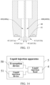
- the liquid injection apparatus 5 comprises an evacuation device 50, a liquid injection device 51 and the liquid injection head 4 provided by the above technical solution.
- the evacuation device 50 and liquid injection device 51 are connected to the liquid injection head 4, and are connected to the first channel 400(with reference to FIG. 11 ).
- liquid injection head 4 By disposing the above liquid injection head 4, liquid can be injected in the internal of the battery 3 provided by the above technical solution, and the liquid injection process is slightly obstructed by the sealing structure 11(with reference to FIG. 12 ).
Landscapes
- Chemical & Material Sciences (AREA)
- Chemical Kinetics & Catalysis (AREA)
- Electrochemistry (AREA)
- General Chemical & Material Sciences (AREA)
- Filling, Topping-Up Batteries (AREA)
Abstract
Description
- The present application claims priority to
Chinese Patent Application No. 202310676863.X, filed with the China National Intellectual Property Administration (CNIPA) on June 8, 2023 Chinese Patent Application No. 202321455918.6, filed with the CNIPA on June 8, 2023 - The present application relates to a field of batteries, especially to an insulation board, a coverplate assembly, a battery, a liquid injection head, and a liquid injection apparatus.
- To facilitate the injection of an electrolyte, a coverplate main body of a power battery is usually provided with a liquid injection hole. After the injection is completed, to prevent leakage, it is common in related technologies to seal the liquid injection hole by placing a sealing rubber particle in it. Additionally, to ensure a high level of controllability when inserting the sealing rubber particle into the liquid injection hole, which guarantees the manufacturing yield of the battery, the industry generally requires a thickness of the sealing rubber particle to be no less than 3.5mm. In other words, the thickness of the sealing rubber particle is often greater than the thickness of the coverplate assembly main body.
- However, such setup can result in the end of the sealing rubber particle entering the interior of the battery after being inserted into the liquid injection hole, thus occupying the space designated for the battery cell inside the battery. This reduces the energy density of the battery cell, causes the battery cell to be compressed, and decreases the safety of the battery.
- The present application provides an insulation board. The insulation board is adapted for a coverplate assembly of a battery. The coverplate assembly comprises a coverplate main body and the insulation board. A liquid injection hole is defined in the coverplate main body. The insulation board comprises:
- a body plate structure, wherein the body plate structure is disposed on a side of the coverplate main body; and
- a sealing structure, wherein the sealing structure comprises a sealing part and a connection part, the sealing part is disposed on a side of the body plate structure near the coverplate main body, the sealing part is configured to seal the liquid injection hole, and the connection part is connected between the sealing part and the body plate structure, the connection part is elastic.
- The present application also provides a coverplate assembly. The coverplate assembly is adapted for a battery, and the coverplate assembly comprises:
- a coverplate main body, wherein a liquid injection hole is defined in the coverplate main body; and
- an insulation board comprising a body plate structure and a sealing structure, wherein the body plate structure is disposed on a side of the coverplate main body, the sealing structure comprises a sealing part and a connection part; the sealing part is disposed on a side of the body plate structure near the coverplate main body, the sealing part is configured to seal the liquid injection hole, the connection part is connected between the sealing part and the body plate structure, the connection part is elastic, the body plate structure is disposed on a side of the coverplate main body, the sealing part is disposed on a side of the body plate structure near the coverplate main body, and the sealing part is able to seal the liquid injection hole.
- The present application also provides a battery. The battery comprises a casing, a battery cell and a coverplate assembly, the coverplate assembly comprises a coverplate main body and an insulation board, a liquid injection hole is defined in the coverplate main body; the insulation board comprises a body plate structure and a sealing structure, the body plate structure is disposed on a side of the coverplate main body, the sealing structure comprises a sealing part and a connection part; the sealing part is disposed on a side of the body plate structure near the coverplate main body, the sealing part is configured to seal the liquid injection hole, the connection part is connected between the sealing part and the body plate structure, the connection part is elastic, the body plate structure is disposed on a side of the coverplate main body, the sealing part is disposed on a side of the body plate structure near the coverplate main body, and the sealing part is able to seal the liquid injection hole;
wherein an aperture is defined in a side of the casing, the battery cell is disposed in an internal of the casing, the coverplate assembly covers the aperture, and the coverplate main body is located on a side of the insulation board away from the battery cell. - The present application also provides a liquid injection head. The liquid injection head is configured to inject liquid in an internal of the battery, the battery comprises a casing, a battery cell and a coverplate assembly, the coverplate assembly comprises a coverplate main body and an insulation board, a liquid injection hole is defined in the coverplate main body; the insulation board comprises a body plate structure and a sealing structure, the body plate structure is disposed on a side of the coverplate main body, the sealing structure comprises a sealing part and a connection part; the sealing part is disposed on a side of the body plate structure near the coverplate main body, the sealing part is configured to seal the liquid injection hole, the connection part is connected between the sealing part and the body plate structure, the connection part is elastic, the body plate structure is disposed on a side of the coverplate main body, the sealing part is disposed on a side of the body plate structure near the coverplate main body, and the sealing part is able to seal the liquid injection hole; wherein an aperture is defined in a side of the casing, the battery cell is disposed in an internal of the casing, the coverplate assembly covers the aperture, and the coverplate main body is located on a side of the insulation board away from the battery cell; the liquid injection head comprises:
- a main body part, wherein a first channel is defined in the main body part, and the main body part is configured to be sealingly connected to coverplate main body to seal the liquid injection hole; and
- an extension portion, wherein the extension portion is protrudingly disposed on the main body part, the extension portion is configured to extend through the liquid injection hole, and a top end of the extension portion is configured to abut the sealing part and enter the internal of the casing, a channel aperture is defined in an outer periphery of the top end, and the channel aperture communicates with the first channel.
- The present application also provides a liquid injection apparatus. The liquid injection apparatus comprises an evacuation device, a liquid injection device, and a liquid injection head, the liquid injection head is configured to inject liquid an internal of the battery, the battery comprises a casing, a battery cell and a coverplate assembly, the coverplate assembly comprises a coverplate main body and an insulation board, a liquid injection hole is defined in the coverplate main body; the insulation board comprises a body plate structure and a sealing structure, the body plate structure is disposed on a side of the coverplate main body, the sealing structure comprises a sealing part and a connection part; the sealing part is disposed on a side of the body plate structure near the coverplate main body, the sealing part is configured to seal the liquid injection hole, the connection part is connected between the sealing part and the body plate structure, the connection part is elastic, the body plate structure is disposed on a side of the coverplate main body, the sealing part is disposed on a side of the body plate structure near the coverplate main body, and the sealing part is able to seal the liquid injection hole; wherein an aperture is defined in a side of the casing, the battery cell is disposed in an internal of the casing, the coverplate assembly covers the aperture, and the coverplate main body is located on a side of the insulation board away from the battery cell; the liquid injection head comprises:
- a main body part, wherein a first channel is defined in the main body part, and the main body part is configured to be sealingly connected to coverplate main body to seal the liquid injection hole; and
- an extension portion, wherein the extension portion is protrudingly disposed on the main body part, the extension portion is configured to extend through the liquid injection hole, and a top end of the extension portion is configured to abut the sealing part and enter the internal of the casing, a channel aperture is defined in an outer periphery of the top end, and the channel aperture communicates with the first channel;
- wherein the evacuation device and the liquid injection device are connected to the liquid injection head, and communicate with the first channel.
- The insulation board, the coverplate assembly, and the battery provided by the present application, by the sealing structure comprising a sealing part and a connection part connected between the sealing part and the body plate structure, enable the sealing part to seal the liquid injection hole under the support of the elastic connection part, and by disposing the sealing structure on the body plate structure, during assembly, the assembly configuration of the sealing structure can be determined by determining an overall assembly configuration of the insulation board to guarantee an assembly yield of the sealing structure. Therefore, an overall thickness of the sealing structure can be less such that the sealing part can be disposed on a side of the body plate structure near the coverplate main body. By disposing the sealing part on a side of the body plate structure near the coverplate main body, namely, by disposing the sealing part between the body plate structure and the coverplate main body, overall occupancy of the sealing structure to a space of a side of the body plate structure away from the coverplate main body (namely, an internal space of the battery) can be reduced, thus improving the energy density and the safety of the battery cell of the battery including the insulation board.
- The liquid injection head and the liquid injection apparatus provided by the present application, by disposing an extension portion able to extend through the liquid injection hole of the sealing part of the insulation board, can utilize a top end of the extension portion to abut the sealing part to unseal the liquid injection hole, and enable the top end to enter a location between the coverplate main body and the body plate structure such that the channel aperture of the outer periphery of the top end communicates with a gap between the coverplate main body and the body plate structure to evacuate and inject liquid in the internal of the battery through the channel aperture of the outer periphery of the top end. Also, during the above evacuation process and liquid injection process, the sealing part would not block the channel aperture to hinder evacuation and liquid injection of the liquid injection head.
-
-
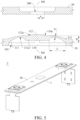
FIG. 1 is a schematic perspective structural view of an insulation board provided by the present application; -
FIG. 2 is an enlarged view of a P portion inFIG. 1 ; -
FIG. 3 is a schematic partial view of an assembly structure of an insulation board and a coverplate main body provided by the present application; -
FIG. 4 is a schematic partial view of exploded structures of the insulation board and the coverplate main body provided by the present application; -
FIG. 5 is a schematic perspective structural view of the coverplate assembly provided by the present application; -
FIG. 6 is a schematic exploded view of a structure of the coverplate assembly provided by the present application; -
FIG. 7 is a schematic perspective structural view of a battery provided by the present application; -
FIG. 8 is a schematic exploded view of the battery provided by the present application; -
FIG. 9 is a schematic perspective structural view of a liquid injection head provided by the present application; -
FIG. 10 is a schematic bottom view of the liquid injection head provided by the present application; -
FIG. 11 is a schematic cross-sectional view along a line A-A inFIG. 10 ; -
FIG. 12 is a schematic structural view of the liquid injection head, the coverplate main body, and the insulation board provided by the present application (when the liquid injection head is configured to inject liquid in the internal of the battery); -
FIG. 13 is a schematic cross-sectional view of a structure of the liquid injection head (the liquid injection head implements liquid injection by simultaneously evacuating and injecting liquid in the internal of the battery) provided by the present application; and -
FIG. 14 is a structure schematic diagram of a structure of a liquid injection apparatus provided by the present application. -
- 1, insulation board; 10, body plate structure; 100, reinforcement rib; 101, first through hole; 102, second through hole; 11, sealing structure; 110, sealing part; 110a, sealing surface; 111, connection part; 111a,
thickness reduction portion 111b,width reduction portion 112, alignment part; 112a, guide surface; - 2, coverplate assembly; 20, coverplate main body; 200, liquid injection hole;
- 3, battery; 30, casing; 300, aperture; 31, battery cell;
- 4, liquid injection head; 40, main body part; 400, first channel; 400a, liquid injection channel; 400b, evacuation channel; 401, sealing ring; 402, disposing
slot 41, extension portion; 410, top end; 410a, top surface; 410b, outer periphery surface; 411, channel aperture; 411a, liquid injection aperture; 411b, evacuation aperture; 412, second channel; - 5, liquid injection apparatus; 50, evacuation device; 51, liquid injection device.
- In the description of the present application, unless specifically defined and restricted otherwise, the terms "connected," "attached," and "fixed" should be broadly understood. For example, the terms can refer to a fixed connection or a detachable connection, or an integral connection; the terms can refer to a mechanical connection or an electrical connection; the terms can refer to direct connection or indirect connection through an intermediary medium. The terms can refer to the internal communication between two elements or the interaction relationship between two elements. A person skilled in the art can understand the specific meaning of the above terms in the context of the present application according to specific circumstances.
- In the present application, unless specifically defined and restricted otherwise, the terms "above" or "below" the second feature can include the first feature being in direct contact with the second feature or not being in direct contact but instead being in contact through another feature between them. Furthermore, the terms "above," "upper," and "on top of" the second feature include both the first feature being directly above and obliquely above the second feature, with a horizontal height of the first feature being higher than a horizontal height of the second feature. The terms "below," "lower," and "underneath" the second feature include both the first feature being directly below and obliquely below the second feature, with a horizontal height of the first feature being lower than a horizontal height of the second feature.
- In the description of the present embodiment, the terms "top," "bottom," "left," "right," "front," "back," and other directional or positional relationships are based on the directions or positional relationships shown in the drawings, and are used for convenience in description and simplification of operations. The above terms do not indicate or imply that the referenced device or element must have a specific orientation, be constructed, or operated in a specific orientation, and therefore should not be understood as a limitation on the present application. Moreover, the terms "first" and "second" are used for descriptive distinction and do not carry special meanings.
- With reference to
FIGs. 1 ,2, and 3 , the present application provides aninsulation board 1 and a coverplate assembly adapted for a battery. The coverplate assembly comprises a coverplatemain body 20 and theinsulation board 1. Aliquid injection hole 200 is defined in the coverplatemain body 20. Theinsulation board 1 comprises abody plate structure 10 and a sealingstructure 11. Thebody plate structure 10 is disposed on a side of the coverplatemain body 20. The sealingstructure 11 comprises a sealingpart 110 and aconnection part 111. The sealingpart 110 is disposed on a side of thebody plate structure 10 near the coverplatemain body 20. The sealingpart 110 is configured to seal theliquid injection hole 200. Theconnection part 111 is connected between the sealingpart 110 and thebody plate structure 10. Theconnection part 111 is elastic. - The sealing
structure 11 comprising the sealingpart 110 and theconnection part 111 connected between the sealingpart 110 and thebody plate structure 10 enables the sealingpart 110 to seal theliquid injection hole 200 under the support of theconnection part 111 being elastic. Even the sealingpart 110 moves to unseal theliquid injection hole 200 due to an effect of an additional external force, after the additional external force vanishes, the sealingpart 110 can be automatically restored to seal theliquid injection hole 200 under an effect of an elastic force of theconnection part 111. Namely, the sealingstructure 11 can automatically seal theliquid injection hole 200 on a side of the coverplatemain body 20 facing theinsulation board 1. - By disposing the sealing
structure 11 in thebody plate structure 10, during assembly, an assembly configuration of the sealingstructure 11 can be determined by determining an overall assembly configuration of theinsulation board 1. For example, a correct orientation of a side of theinsulation board 1 facing the coverplatemain body 20 is determined to determine that the sealingstructure 11 of thebody plate structure 10 is in a correct assembly configuration. Because an overall volume of theinsulation board 1 is greater compared to the sealingstructure 11, the overall assembly configuration of theinsulation board 1 is easily determined and theoverall insulation board 1 is easily kept in a correct configuration for assembly, thereby easily guaranteeing an assembly yield of the sealingstructure 11. Therefore, an overall thickness of the sealingstructure 11 can be less to enable the sealingpart 110 to be disposed on a side of thebody plate structure 10 near the coverplatemain body 20. By disposing the sealingpart 110 on a side of thebody plate structure 10 near the coverplatemain body 20, namely, by disposing the sealingpart 110 between thebody plate structure 10 and the coverplatemain body 20, overall occupancy of the sealingstructure 11 to a space of a side of thebody plate structure 10 away from the coverplate main body 20 (namely, an internal space of the battery) can be reduced, thereby improving the energy density and the safety of the battery cell of the battery including theinsulation board 1. - With reference to
FIGs. 2, 3 , and4 , in some possible embodying ways, a side of the sealingpart 110 away from thebody plate structure 10 can comprise asealing surface 110a. The sealingsurface 110a is configured to abut the coverplatemain body 20 to seal theliquid injection hole 200, thereby implementing the sealing function of the sealingpart 110 to theliquid injection hole 200. - In some possible embodying ways, a height of the
connection part 111 protruding from thebody plate structure 10 is less than or equal to a height of the sealingsurface 110a protruding from thebody plate structure 10 to prevent interference of the structure of theconnection part 111 with the coverplatemain body 20 affecting abutment tightness of the sealingsurface 110a and the coverplatemain body 20, thereby preventing influence of sealing effect of the sealingsurface 110a to theliquid injection hole 200. - The inventor discovers upon further research that to have a better sealing effect of the sealing
surface 110a to theliquid injection hole 200, a greater effective abutment area between the sealingsurface 110a and the coverplatemain body 20 is required, namely, an area of the sealingsurface 110a is required to be greater than an area of theliquid injection hole 200 defined in the coverplatemain body 20, by a certain extent. Furthermore, the greater area of the sealingsurface 110a, although resulting in the better sealing effect of the sealingsurface 110a to theliquid injection hole 200, also results in the greater volume of the sealingpart 110. The greater area of the sealingsurface 110a in one aspect influences the compactness of an overall structure of theinsulation board 1, and in another aspect requires greater support of theconnection part 111 to the sealingpart 110, thereby resulting in higher requirement to elastic support capability of theconnection part 111. Therefore, an area of the sealingpart 110 is required to be greater than an area of theliquid injection hole 200 defined in a side surface of the coverplatemain body 20 facing thebody plate structure 10 by a certain extent, but the area of the sealingsurface 110a should not be too large. - In the related art, the
liquid injection hole 200 is usually a circular hole, and a radius of theliquid injection hole 200 defined in the side surface of the coverplatemain body 20 facing thebody plate structure 10 is a, the radius a usually can be 1.5mm. Accordingly, in some possible embodying ways, the sealingsurface 110a comprises an outer circumscribed circle diameter R, and the outer circumscribed circle diameter R can fulfill: 4mm≤R≤8mm, for example, outer circumscribed circle diameter R can be 4mm, 4.5mm, 5mm, 5.5mm, 6mm, 6.5mm, 7mm, 7.5mm, or 8mm. - In another some possible embodiments, an area of the sealing
surface 110a can be S1, a hole area of theliquid injection hole 200 on the side surface of the coverplatemain body 20 facing thebody plate structure 10 can be S2, a ratio of the area S1 to the area S2 can fulfill: 2≤S1/S2≤5, for example, S1/S2 can be : 2, 2.5, 3, 3.5, 4, 4.5, or 5, wherein units of the area S1 and the area S2 are mm2. - As described above, a radius of the
liquid injection hole 200 is a, therefore, the area S2 = πa2, and 2≤S1/S2≤5 is equal to 2≤S1/(πa2)≤5, wherein a unit of the radius a is mm. - Understandably, for the sealing
surface 110a comprising the same outer circumscribed circle diameter R and a different shape, the area S1 of the sealingsurface 110a is also different. To make both the sealing capability of the sealingsurface 110a and the structure volume of the sealingpart 110 more ideal, in some possible embodying ways, the outer circumscribed circle diameter R of the sealingsurface 110a can fulfill: 4mm≤R≤8mm while the area S1 of the sealingsurface 110a and the area S2 of the hole in the side surface of the coverplatemain body 20 facing thebody plate structure 10 fulfill: 2≤S1/S2≤5. - In some possible embodiments, the sealing
surface 110a can be a circular surface, an equilateral triangular surface, an equilateral quadrilateral surface, an equilateral pentagonal surface, an equilateral hexagonal surface, or another equilateral polygonal surface. Correspondingly, the sealingpart 110 can be a cylindrical, triangular prism, quadrilateral prism, pentagonal prism, hexagonal prism, or other prismatic structure. As a result, distribution of the effective abutment area between the sealingsurface 110a and the cover platemain body 20 surrounding theliquid injection hole 200 is more uniform, the sealing effect of the sealingsurface 110a on theliquid injection hole 200 is more uniform, and the structure of the sealingpart 110 is simpler and easier to manufacture. - In some possible embodying ways, the sealing
surface 110a can comprise a first axial line M1, and the sealingstructure 11 can further comprise analignment part 112. Thealignment part 112 is protrudingly disposed on the sealingsurface 110a. Thealignment part 112 is configured to extend in an internal of theliquid injection hole 200 such that the first axial line M1 of the sealingsurface 110a substantially coincides with a second axial line M2 of theliquid injection hole 200, thereby reducing an offset between the sealingsurface 110a and theliquid injection hole 200. As a result, relative locations of the sealingsurface 110a and theliquid injection hole 200 are closer to the idea state of the design such that distribution of the effective abutment area of the sealingsurface 110a and the coverplatemain body 20 surrounding theliquid injection hole 200 is more uniform, and the sealing effect of the sealingsurface 110a to theliquid injection hole 200 is more balanced. - In some possible embodying ways, an outer periphery of the
alignment part 112 can comprise aguide surface 112a. Theguide surface 112a is disposed to guide thealignment part 112 to extend in theliquid injection hole 200 such that in the case that a certain offset occurs between thealignment part 112 and theliquid injection hole 200, thealignment part 112 can be self-aligned with theliquid injection hole 200 through theguide surface 112a to enable thealignment part 112 to extend in the internal of theliquid injection hole 200 and drive the first axial line M1 of the sealingpart 110 to be automatically aligned with the second axial line M2 of theliquid injection hole 200. - In particular, in the case that a certain offset occurs between the
alignment part 112 and theliquid injection hole 200, theguide surface 112a can abut a hole wall of theliquid injection hole 200 to enable thealignment part 112 to extend in theliquid injection hole 200 under an effect of a reaction force from the hole wall of theliquid injection hole 200. - For example, the
alignment part 112 can be a conical frustum structure protrudingly disposed on the sealingsurface 110a, and thealignment part 112 utilizes the first axial line M1 as an axis, an outer periphery surface of the conical frustum structure forms aguide surface 112a such that thealignment part 112 can implement a function of driving the sealingpart 110 for automatic alignment, and the structure of thealignment part 112 is simple. - In another example, the
alignment part 112 can be a ring structure surrounding the first axial line M1. An outer periphery of the ring structure forms theguide surface 112a. Alternatively, thealignment part 112 can be plural, thealignment parts 112 are arranged around the first axial line M1 and spaced from each other. Outer surfaces of thealignment parts 112 away from the first axial line M1 form theguide surface 112a. Understandably, as long as thealignment part 112 can be automatically aligned with and extend in theliquid injection hole 200 to drive the first axial line M1of the sealingpart 110 to be automatically aligned with the second axial line M2 of theliquid injection hole 200, the present embodiment has no specific limit to the structure of thealignment part 112. - In some possible embodying ways, the
connection part 111 can be connected between an outer periphery of the sealingpart 110 and thebody plate structure 10 such that along a direction perpendicular to thesealing surface 110a, structures of theconnection part 111 and the sealingpart 110 are more compact, and the sealingstructure 11 is more suitably disposed between thebody plate structure 10 and the coverplatemain body 20. - In some possible embodying ways, the
connection part 111 can be an at least partially bent strip-like structure, two opposite ends of theconnection part 111 are connected to the sealingpart 110 and thebody plate structure 10 respectively. Also, theconnection part 111 can be plural. Theconnection parts 111 are arranged around the sealingpart 110 and spaced from each other such that theconnection part 111 can provide the sealingpart 110 with a greater elastic support force by the at least partially bent structure. Furthermore, increasing a quantity of theconnection parts 111 can increase force points of the elastic support force of theconnection parts 111 to the sealingpart 110, thus improving the balance of a support effect of theconnection parts 111 to the sealingpart 110 to improve the consistency of abutment tightness of portions of the sealingsurface 110a with the coverplatemain body 20. - In some possible embodying ways, the
connection parts 111 can be arranged equidistantly around the sealingpart 110 such that the balance of the support effect of theconnection parts 111 to the sealingpart 110 is optimal, and the consistency of abutment tightness of portions of the sealingsurface 110a with the coverplatemain body 20 is also optimal. - In some possible embodying ways, the
connection part 111 can be formed as a strip-like structure bent and protruding away from thebody plate structure 10 such that theconnection part 111 can provide the sealingpart 110 with the greater elastic support force while the structure of theconnection part 111 becomes simpler. - Along the direction perpendicular to the
sealing surface 110a, theconnection part 111 comprises a height H. Along a direction parallel to thesealing surface 110a, theconnection part 111 comprises a length L. The inventor discovers upon further research that the less a ratio H/L of the height H to the length L of theconnection part 111 is, the less an elastic support force can be provided by theconnection part 111 for the sealingpart 110. The greater the ratio H/L is, the greater the stress is generated on the structure of theconnection part 111 during elastic deformation, and the easier theconnection part 111 is ruptured. Therefore, the ratio H/L of the height H to the length L of theconnection part 111 should be neither too large or too small. Accordingly, in some possible embodying ways, the ratio H/L of the height H to the length L of theconnection part 111 can fulfill: 0.2≤H/L≤1.5. For example, H/L can be 0.2, 0.3, 0.4, 0.5, 0.6, 0.7, 0.8, 0.9, 1, 1.1, 1.2, 1.3, 1.4, or 1.5, wherein units of the height H and the length L are mm. - Along the direction perpendicular to the
sealing surface 110a, theconnection part 111 comprises a thickness. In some possible embodying ways, theconnection part 111 can be a structure with an uneven thickness. Namely, theconnection part 111 can comprise at least onethickness reduction portion 111a such that when elastic deformation occurs on theconnection part 111, the elastic deformation is mainly concentrated on thethickness reduction portion 111a to improve controllability of the elastic deformation of theconnection part 111 to better implement simulation calculations to the stress and structure deformation on theconnection part 111. - A minimum of a thickness of the
connection part 111 can be t1. Namely, a minimum thickness of thethickness reduction portion 111a of theconnection part 111 can be t1. The thinner the thickness t1 is, the greater the elastic deformation can occur on thethickness reduction portion 111a. However, the less a structural strength of thethickness reduction portion 111a is, the less an elastic support force can be provided by theconnection part 111 for the sealingpart 110. The thicker the thickness t1 is, the less the elastic deformation can occur on thethickness reduction portion 111a. The less a concentration function of thethickness reduction portion 111a to the elastic deformation of theconnection part 111 is, the lower the controllability of the elastic deformation of theconnection part 111 is, however, the greater the elastic support force is provided by theconnection part 111 for the sealingpart 110. Therefore, the thickness t1 should be neither too thin nor too thick. Accordingly, in some possible embodying ways, the thickness t1 can fulfill: 0.2mm≤t1≤1mm. For example, the thickness t1 can be 0.2mm, 0.3mm, 0.4mm, 0.5mm, 0.6mm, 0.7mm, 0.8mm, 0.9mm, or 1mm. - Along the direction parallel to the
sealing surface 110a, theconnection part 111 comprises a width. In another some possible embodiments, theconnection part 111 can be a structure with an uneven width, namely, theconnection part 111 can comprise at least onewidth reduction portion 111b such that theconnection part 111 is easily bent elastically along a width direction on thewidth reduction portion 111b to enable the sealingpart 110 supported by theconnection part 111 to slightly twist along a circumference. Thus, under in the case that the sealingpart 110 is required to slightly twist due to the manufacturing error to enable thesealing surface 110a to tightly abut the coverplatemain body 20, theconnection part 111 can be bent along the width direction on thewidth reduction portion 111b to enable the sealingpart 110 to slightly twist such that the sealingsurface 110a automatically tightly abuts the coverplatemain body 20 to provide the better sealing effect of the sealingsurface 110a to theliquid injection hole 200. - A minimum of the width of the
connection part 111 can be t2. Namely, the minimum width of thewidth reduction portion 111b of theconnection part 111 can be t2. The narrower the width t2 is, the greater an elastic bending can occur on thewidth reduction portion 111b, but the less a structural strength of thewidth reduction portion 111b is, and the less an elastic support force can be provided by theconnection part 111 for the sealingpart 110. The wider the width t2 is, the less the elastic bending can occur on thewidth reduction portion 111b, the less an amplitude of the twist can occur on the sealingpart 110, the more limited the function of the sealingpart 110 automatically adjusting the orientation to enable thesealing surface 110a to tightly abut the coverplatemain body 20 is, but the greater the elastic support force can be provided by theconnection part 111 for the sealingpart 110. Therefore, the width t2 should not be too narrow or too wide. Accordingly, in some possible embodying ways, the width t2 can fulfill: 0.2mm≤t2≤1mm. For example, the width t2 can be 0.2mm, 0.3mm, 0.4mm, 0.5mm, 0.6mm, 0.7mm, 0.8mm, 0.9mm, or 1mm. - In some possible embodying ways, the
connection part 111 can be a structure with an uneven thickness and an uneven width. Namely, theconnection part 111 can comprise at least onethickness reduction portion 111a and at least onewidth reduction portion 111b such that theconnection part 111 is easily bent elastically along the width direction on thewidth reduction portion 111b while the controllability of the elastic deformation of theconnection part 111 is increased, thereby enabling the sealingsurface 110a more easily achieving automatic abutment against the coverplatemain body 20 to provide the better sealing effect of the sealingsurface 110a to theliquid injection hole 200. - In some possible embodying ways, a minimum of a thickness of the
connection part 111 can be t1. Namely, a minimum thickness ofthickness reduction portion 111a of theconnection part 111 can be t1, the thickness t1 can fulfill: 0.2mm≤t1≤1mm. Also, a minimum of the width of theconnection part 111 can be t2. Namely, a minimum width of thewidth reduction portion 111b of theconnection part 111 can be t2, and the width t2 can fulfill: 0.2mm≤t2≤1mm. Effects obtained from values of the thickness t1 and the width t2 can refer to the above-mentioned technical solution, and no repeated elaboration is here. - In some possible embodying ways, the sealing
structure 11 and thebody plate structure 10 can be formed into one piece, for example, the sealingstructure 11 and thebody plate structure 10 can be formed integrally. Alternatively, the sealingstructure 11 and thebody plate structure 10 can be connected together by adhesive, soldered, or securely connected together to form into one piece such that the overall structure of theinsulation board 1 is more stable. - Because the
body plate structure 10 needs to have an insulation property, thebody plate structure 10 is usually plastic with an excellent insulation property. Also, because plastic is usually elastic in a certain extent, in some possible embodying ways, the sealingstructure 11 and thebody plate structure 10 can be the same plastic material, and theoverall insulation board 1 can be formed integrally by an injection molding process. Namely, the sealingstructure 11 and thebody plate structure 10 can be formed into one piece the injection molding process, thereby simplifying the manufacturing process of theinsulation board 1 and enhancing the connection stability of the sealingstructure 11 and thebody plate structure 10. - With reference to
FIGs. 1 ,2, and 3 again, in some possible embodying ways, areinforcement rib 100 can be protrudingly disposed on a surface of thebody plate structure 10 to enhance the structural strength of thebody plate structure 10. - Understandably, a portion of the
body plate structure 10 disposed with the protrudingreinforcement rib 100, compared to a portion of thebody plate structure 10 without the protrudingreinforcement rib 100, comprises an overall structure with a thicker thickness. Therefore, during the injection molding process, the injection molding material of the portion of thebody plate structure 10 disposed with the protrudingreinforcement rib 100 cools down more slowly, and the solidification of the injection molding material is more time consuming. Accordingly, in some possible embodying ways, theconnection part 111 can be connected between the sealingpart 110 and thereinforcement rib 100 such that during the injection molding process, injection molding material can enter theconnection part 111 from thereinforcement rib 100 to form the structures of theconnection part 111 and the sealingpart 110. The temperature of the injection molding material entering theconnection part 111 is higher and can reduce an issue of insufficient material flow caused by the injection molding material prematurely cooling and solidifying to lead to defects in the sealingstructure 11 due to material shortage, thereby improving the yield rate of the injection molding process of the sealingstructure 11. - In some possible embodying ways, a first through
hole 101 can be defined in thebody plate structure 10. The first throughhole 101 is configured to correspond to theliquid injection hole 200. The sealingstructure 11 can be disposed in the first throughhole 101, thereby facilitating an electrolyte quickly entering the internal of the battery through the first throughhole 101 when the liquid injection head injects liquid in the internal of the battery (namely, a side of thebody plate structure 10 away from the coverplate main body 20) from theliquid injection hole 200. - In some possible embodying ways, a plurality of second through
holes 102, arranged in an array, can be defined in thebody plate structure 10, thereby facilitating the electrolyte seeping into the internal of the battery through the second throughholes 102 when the liquid injection head injects liquid in the internal of the battery (namely, the side of thebody plate structure 10 away from the coverplate main body 20) from theliquid injection hole 200,. - In some possible embodying ways, the
body plate structure 10 can be formed with both the first throughhole 101 and the second throughholes 102 as described above such that 101 the electrolyte quickly enters the internal of the battery through the first through hole, and the electrolyte, not entering the first throughhole 101, seeps into the internal of the battery through the second throughholes 102, thereby improving the liquid injection efficiency of the electrolyte. - With reference to
FIGs. 3 ,5 , and6 , the present application provides acoverplate assembly 2 adapted for a battery. thecoverplate assembly 2 comprises a coverplatemain body 20 and theinsulation board 1 provided by the above technical solution. Aliquid injection hole 200 is defined in the coverplatemain body 20. Thebody plate structure 10 is disposed on a side of the coverplatemain body 20. The sealingpart 110 is disposed on a side of thebody plate structure 10 near the coverplatemain body 20, and the sealingpart 110 can seal theliquid injection hole 200. Because the sealingpart 110 is located between thebody plate structure 10 and the coverplatemain body 20, the sealingstructure 11 overall occupies little of a space on a side of thebody plate structure 10 away from the coverplate main body 20 (namely, the internal space of the battery), thereby able to improve the energy density and safety of the battery cell of the battery including thecoverplate assembly 2. - In some possible embodying ways, an interval distance is defined between the coverplate
main body 20 and thebody plate structure 10. The interval distance is less than a protruding height of the sealingsurface 110a protruding from thebody plate structure 10 such that the sealingstructure 11 is overall tightly pressed between thebody plate structure 10 and the coverplatemain body 20 when thebody plate structure 10 is disposed on a side of the coverplatemain body 20. Namely, the sealingsurface 110a is enabled to tightly abut a surface of the coverplatemain body 20. Also, theconnection part 111 is squeezed to generate certain elastic deformation to continuously apply an elastic force to the sealingpart 110 such that the sealingsurface 110a is tightly pressed on the surface of the coverplatemain body 20 more stably to better stabilize the sealing effect of the sealingsurface 110a to theliquid injection hole 200. - Understandably, the less the interval distance is between the coverplate
main body 20 and thebody plate structure 10, the greater the pressing force with which thesealing surface 110a abuts and is tightly pressed against the surface of the coverplatemain body 20, leading to a more stable sealing effect of theliquid injection hole 200. However, the interval distance between the coverplatemain body 20 and thebody plate structure 10 is for the liquid injection head entering the interval distance to implement liquid injection. The less the space of the evacuation operation is, the greater the interval distance is between the coverplatemain body 20 and thebody plate structure 10, and the less the pressing force with which thesealing surface 110a abuts and is pressed against the surface of the coverplatemain body 20, leading to difficulty maintaining the stability of the sealing effect of theliquid injection hole 200. However, the interval distance between the coverplatemain body 20 and thebody plate structure 10 is for the liquid injection head entering the interval distance to implement liquid injection. The greater the space of the evacuation operation is, the less a specific interval distance is between the coverplatemain body 20 and thebody plate structure 10. Selection can be made according to usage requirements, and the present embodiment imposes no specific limitations. - With reference to
FIGs. 7 and8 , the present application provides abattery 3, thebattery 3 comprises acasing 30, abattery cell 31, and thecoverplate assembly 2 provided by the above technical solution. A side of thecasing 30 comprises anaperture 300. Thebattery cell 31 is disposed in an internal of thecasing 30. Thecoverplate assembly 2 covers theaperture 300, and the coverplatemain body 20 is located on a side of theinsulation board 1 away from thebattery cell 31. Because the sealing part 110 (with reference toFIG. 3 ) occupies little of the internal space of thebattery 3, the energy density of thebattery cell 31 of thebattery 3 is greater, and the use safety of thebattery 3 is higher. - With reference to
FIGs. 9, 10 ,11 , and12 , the present application provides aliquid injection head 4, theliquid injection head 4 is configured to inject liquid in the internal of thebattery 3 provided by the above technical solution. Theliquid injection head 4 comprises amain body part 40 and anextension portion 41. Afirst channel 400 is defined in themain body part 40. Themain body part 40 is configured to be sealingly connected to the coverplatemain body 20 to seal theliquid injection hole 200. Theextension portion 41 is protrudingly disposed on themain body part 40, and theextension portion 41 is configured to extend through theliquid injection hole 200. Atop end 410 of theextension portion 41 is configured to abut the sealingpart 110 and enter the internal of thecasing 30. Achannel aperture 411 is defined in an outer periphery of thetop end 410, and thechannel aperture 411 communicates with thefirst channel 400. - By disposing the
extension portion 41 able to extend through theliquid injection hole 200, thetop end 410 of theextension portion 41 can be used to abut the sealingpart 110 to unseal theliquid injection hole 200 and enable thetop end 410 to enter a location between the coverplatemain body 20 and thebody plate structure 10 such that thechannel aperture 411 of the outer periphery of thetop end 410 communicates with the gap between the coverplatemain body 20 and thebody plate structure 10 to implement evacuation and liquid injection to an internal of thebattery 3 by thechannel aperture 411. During the process, the sealingpart 110 would not obstruct thechannel aperture 411 to hinder evacuation and liquid injection of theliquid injection head 4. - As described above, when the
alignment part 112 is protrudingly disposed on the sealingpart 110, theextension portion 41 can also abut thealignment part 112, thereby enabling thealignment part 112 to drive the sealingpart 110 to move to unseal theliquid injection hole 200. - A protruding height of the
extension portion 41 protruding from themain body part 40 is c. To make thechannel aperture 411 defined in the outer periphery of thetop end 410 entering a location between the coverplatemain body 20 and thebody plate structure 10 to communicate with the gap between the coverplatemain body 20 and thebody plate structure 10, the protruding height c is required to be greater. However, when too large, the protruding height c easily results in a condition of thetop end 410 of theextension portion 41 abutting the sealingpart 110 to interfere with thebattery cell 3 during the liquid injection process to lead to damage to thebattery cell 31. Accordingly, in some possible embodying ways, the height c can fulfill: 0.5mm≤c≤1mm, for example, height c can be 0.5mm, 0.6mm, 0.7mm, 0.8mm, 0.9mm, or 1mm. - In some possible embodying ways, the
top end 410 can comprise atop surface 410a away from themain body part 40. Thetop surface 410a is configured to abut the sealingpart 110 and enter the internal of thebattery 3. Asecond channel 412 can be defined in thetop surface 410a. Thesecond channel 412 communicates with thefirst channel 400. thechannel aperture 411 is defined in an outer periphery and thetop surface 410a of thetop end 410, and thechannel aperture 411 communicates with thesecond channel 412. As a result, during the manufacturing process of theliquid injection head 4, theextension portion 41 can be processed on a side of thetop surface 410a to form thechannel aperture 411 communicating with thesecond channel 412, the forming process of thechannel aperture 411 is simpler. Especially, when thechannel aperture 411 is plural, a plurality ofchannel apertures 411 with different aperture directions can be manufactured and obtained without changing a processing direction, thereby simplifying process steps. - Furthermore, defining the
channel aperture 411 in the outer periphery and thetop surface 410a of thetop end 410 makes no space between thechannel aperture 411 and the sealingpart 110 when thetop surface 410a abuts the sealingpart 110 such that bubble formation is less like to occur between thechannel aperture 411 and the sealingpart 110 during the liquid injection process. - According to actual demands of usage and design, in some possible embodying ways, the outer periphery of the
top end 410 can comprise anouter periphery surface 410b connected to thetop surface 410a. Thechannel aperture 411 is disposed on theouter periphery surface 410b. Theouter periphery surface 410b can be perpendicular to or inclined to thetop surface 410a. Alternatively, theouter periphery surface 410b can also be an arc surface or an irregular surface. - In the related art, based on the operational mode of the
liquid injection head 4, there are generally two types of liquid injection heads 4. One type is aliquid injection head 4 that achieves breathing-type liquid injection by alternately performing evacuation and liquid injection within thebattery 3. The other type is aliquid injection head 4 that performs both evacuation and liquid injection simultaneously within thebattery 3 to achieve liquid injection. Next, with reference to the accompanying drawings, the specific structure of theliquid injection head 4 provided in the present embodiment will be described when theliquid injection head 4 provided in the present embodiment is one of these two types of liquid injection heads 4. - With reference to
FIGs. 10 ,11 , and12 , in some possible embodying ways, theliquid injection head 4 is configured to implement a breathing-type liquid injection to the internal of thebattery 3. During the evacuation process of theliquid injection head 4, thechannel aperture 411 of theliquid injection head 4 serves as an air extraction port, and thefirst channel 400 of theliquid injection head 4 serves as an evacuation channel. During the liquid injection process of theliquid injection head 4, thechannel aperture 411 of theliquid injection head 4 serves as a liquid injection port, and thefirst channel 400 of theliquid injection head 4 serves as a liquid injection channel. - In some possible embodying ways, the
channel aperture 411 can be plural, thechannel apertures 411 are arranged along a circumference of thetop end 410 and spaced from each other. Thechannel apertures 411 communicate with thefirst channel 400 such that increasing a quantity of thechannel apertures 411 increases a total aperture area of thechannel apertures 411, thereby lowering a flow rate of fluid in thechannel apertures 411 during the evacuation process and liquid injection process to further reduce the influence of the airflow and injected electrolyte to the internal of thebattery 3. - With reference to
FIG. 13 , in some possible embodying ways, theliquid injection head 4 implements liquid injection by simultaneously evacuating and injecting liquid in the internal of thebattery 3. Thefirst channel 400 can be plural, and thefirst channels 400 are spaced from each other. In thefirst channels 400. At least one of thefirst channels 400 is aliquid injection channel 400a, and at least one of remains of thefirst channels 400 is anevacuation channel 400b. Thechannel aperture 411 can also be plural, and thechannel apertures 411 are spaced from each other. In thechannel apertures 411, at least one of thechannel apertures 411 is aliquid injection aperture 411a, and at least one of remains of thechannel apertures 411 is anevacuation aperture 411b. Theliquid injection aperture 411a communicates with theliquid injection channel 400a, and theevacuation aperture 411b communicates with theevacuation channel 400b such that theliquid injection head 4 can evacuate the internal of thebattery 3 by theevacuation channel 400b and theevacuation aperture 411b while liquid injection the internal of thebattery 3 by theliquid injection channel 400a and theliquid injection aperture 411a to maintain an air pressure of the internal of thebattery 3 within a more stable range during liquid injection. - In some possible embodying ways, the
liquid injection apertures 411a can communicate with the sameliquid injection channel 400a to lower a flow rate of the electrolyte injected into theliquid injection apertures 411a during the liquid injection process to lower the influence to the internal of thebattery 3 due to the impact of the electrolyte to the internal of thebattery 3. - In some possible embodying ways, the
evacuation aperture 411b can communicate with thesame evacuation channel 400b to lower an airflow rate of theevacuation aperture 411b to further reduce the influence of an airflow to the internal of thebattery 3 during the evacuation process. - In some possible embodying ways, a sealing
ring 401 can also be defined in themain body part 40. The sealingring 401 is located on a side of themain body part 40 disposed with the protrudingextension portion 41, and surrounds an outer periphery of theextension portion 41. Themain body part 40 sealingly abuts the coverplatemain body 20 through the sealingring 401 to have a better sealing effect to theliquid injection hole 200 to further better prevent air leakage between themain body part 40 and the coverplatemain body 20 during the evacuation process and liquid leakage between themain body part 40 and the coverplatemain body 20 during the liquid injection process. - In some possible embodying ways, a disposing
slot 402 can be defined in a surface of themain body part 40 and surround theextension portion 41. The sealingring 401 is partially located in the disposingslot 402 and is connected to a slot wall of the disposingslot 402 such that an effective connection area of the sealingring 401 and themain body part 40 is greater and connection robustness of the sealingring 401 and themain body part 40 is better. - With reference to
FIG. 14 , the present application provides aliquid injection apparatus 5. Theliquid injection apparatus 5 comprises anevacuation device 50, aliquid injection device 51 and theliquid injection head 4 provided by the above technical solution. Theevacuation device 50 andliquid injection device 51 are connected to theliquid injection head 4, and are connected to the first channel 400(with reference toFIG. 11 ). By disposing the aboveliquid injection head 4, liquid can be injected in the internal of thebattery 3 provided by the above technical solution, and the liquid injection process is slightly obstructed by the sealing structure 11(with reference toFIG. 12 ).
Claims (20)
- An insulation board (1), adapted for a coverplate assembly (2) of a battery (3), wherein the coverplate assembly (2) comprises a coverplate main body (20) and the insulation board (1), a liquid injection hole (200) is defined in the coverplate main body (20), and the insulation board (1) comprises:a body plate structure (10), wherein the body plate structure (10) is disposed on a side of the coverplate main body (20); anda sealing structure (11), wherein the sealing structure (11) comprises a sealing part (110) and a connection part (111), the sealing part (110) is disposed on a side of the body plate structure (10) near the coverplate main body (20), the sealing part (110) is configured to seal the liquid injection hole (200), and the connection part (111) is connected between the sealing part (110) and the body plate structure (10), the connection part (111) is elastic.
- The insulation board (1) according to claim 1, wherein a side of the sealing part (110) away from the body plate structure (10) comprises a sealing surface (110a), and the sealing surface (110a) is configured to abut the coverplate main body (20) to seal the liquid injection hole (200); and
a height of the connection part (111) protruding from the body plate structure (10) is less than or equal to a height of the sealing surface (110a) protruding from the body plate structure (10). - The insulation board (1) according to claim 2, wherein the sealing surface (110a) comprises an outer circumscribed circle diameter R, 4mm≤R≤8mm, and/or, an area of the sealing surface (110a) is S1, a radius of the liquid injection hole (200) is a, 2≤S1/ (πa2) ≤5, wherein a unit of the area S1 is mm2, and a unit of the radius a is mm.
- The insulation board (1) according to claim 2, wherein the sealing surface (110a) comprises a first axial line (M1), the sealing structure (11) further comprises an alignment part (112), the alignment part (112) is protrudingly disposed on the sealing surface (110a), the alignment part (112) is configured to extend in an internal of the liquid injection hole (200) such that the first axial line of the sealing surface (110a) coincides with a second axial line of the liquid injection hole (200).
- The insulation board (1) according to claim 4, wherein an outer periphery of the alignment part (112) comprises a guide surface (112a), and the guide surface (112a) is disposed to guide the alignment part (112) to extend in the liquid injection hole (200).
- The insulation board (1) according to claim 5, wherein the alignment part (112) is a conical frustum structure, the alignment part uses the first axial line (M1) as an axis, and an outer periphery surface of the conical frustum structure forms the guide surface (112a).
- The insulation board (1) according to claim 2, wherein the connection part (111) is a at least partially bent strip-like structure, two opposite ends of the connection part (111) are connected to the sealing part (110) and the body plate structure (10) respectively, the connection part (111) is plural, and the connection parts (111) are arranged around the sealing part (110) and are spaced from each other.
- The insulation board (1) according to claim 7, wherein the connection part (111) forms a strip-like structure bent and protruding away from the body plate structure (10), along a direction perpendicular to the sealing surface (110a), the connection part (111) comprises a height H, and along a direction parallel to the sealing surface (110a), the connection part (111) comprises a length L, 0.2≤H/L≤1.5.
- The insulation board (1) according to claim 7, wherein along a direction perpendicular to the sealing surface (110a), the connection part (111) comprises a thickness, the connection part (111) is a structure with an uneven thickness; and/or,
along a direction parallel to the sealing surface (110a) the connection part (111) comprises a width, and the connection part (111) is a structure with an uneven width. - The insulation board (1) according to claim 9, wherein when the connection part (111) is the structure with the uneven thickness, a minimum of the thickness is t1, 0.2mm≤t1≤1mm; and/or
when the connection part (111) is a structure with an uneven width, a minimum of the width is t2, 0.2mm≤t2≤1mm. - The insulation board (1) according to any one of claims 1-10, wherein a reinforcement rib (100) is protrudingly disposed on a surface of the body plate structure (10), and the connection part (111) is connected between the sealing part (110) and the reinforcement rib (100).
- The insulation board (1) according to any one of claims 1-10, wherein a first through hole (101) is defined in the body plate structure (10), the first through hole (101) is configured to correspond to the liquid injection hole (200), and the sealing structure (11) is disposed in the first through hole (101).
- A coverplate assembly (2), adapted for a battery (3), and the coverplate assembly (2) comprising:a coverplate main body (20), wherein a liquid injection hole (200) is defined in the coverplate main body (20); andthe insulation board (1) according to any one of claims 1-12, wherein the body plate structure (10) is disposed on a side of the coverplate main body (20), the sealing part (110) is disposed on a side of the body plate structure (10) near the coverplate main body (20), and the sealing part (110) is able to seal the liquid injection hole (200).
- A battery (3), wherein the battery (3) comprises a casing (30), a battery cell (31), and the coverplate assembly (2) according to claim 12, an aperture (300) is defined in a side of the casing (30), the battery cell (31) is disposed on an internal of the casing (30), the coverplate assembly (2) covers the aperture (300), and the coverplate main body (20) is located on a side of the insulation board (1) away from the battery cell (31).
- A liquid injection head (4), wherein the liquid injection head (4) is configured to inject liquid in an internal of the battery (3) according to claim 13, and the liquid injection head (4) comprises:a main body part (40), wherein a first channel (400) is defined in the main body part (40), and the main body part (40) is configured to be sealingly connected to the coverplate main body (20) to seal the liquid injection hole (200); andan extension portion (41), wherein the extension portion (41) is protrudingly disposed on the main body part (40), and the extension portion (41) is configured to extend through the liquid injection hole (200), a top end (410) of the extension portion (41) is configured to abut the sealing part (110) and enter the internal of the casing (30), a channel aperture (411) (300) is defined in an outer periphery of the top end (410), and the channel aperture (411) (300) communicates with the first channel (400).
- The liquid injection head (4) according to claim 15, wherein a protruding height of the extension portion (41) protruding from the main body part (40) is c, 0.5mm≤c≤1mm.
- The liquid injection head (4) according to claim 15, wherein the top end (410) comprises a top surface (410a) away from the main body part (40), and the top surface (410a) is configured to abut the sealing part (110) and enter the internal of the battery (3); and
a second channel (412) is defined in the top surface (410a), the second channel (412) communicates with the first channel (400), the channel aperture (411) (300) is defined in the outer periphery of the top end (410) and the top surface (410a), and the channel aperture (411) (300) communicates with the second channel (412). - The liquid injection head (4) according to any one of claims 15-17, wherein the channel aperture (411) (300) is plural, the channel apertures (411) (300) are spaced from each other along the outer periphery of the top end (410), and the channel apertures (411) (300) communicate with the first channel (400).
- The liquid injection head (4) according to any one of claims 15-17, wherein the first channel (400) is plural, the first channels (400) are spaced from each other, in the first channels (400), at least one of the first channels (400) is a liquid injection channel (400a), and at least one of remains of the first channels (400) is an evacuation channel (400b); and
the channel aperture (411) (300) is plural, the channel apertures (411) (300) are spaced from each other, in the channel apertures (411) (300), at least one of the channel apertures (411) (300) is a liquid injection aperture (411a) (300), at least one of remains of the channel apertures (411) (300) is an evacuation aperture (411b) (300), the liquid injection aperture (411a) (300) communicates with the liquid injection channel (400a), and the evacuation aperture (411b) (300) communicates with the evacuation channel (400b). - A liquid injection apparatus (5), the liquid injection apparatus (5) comprises an evacuation device (50), a liquid injection device (51) and the liquid injection head (4) according to any one of claims 15-19, and the evacuation device (50) and the liquid injection device (51) are connected to the liquid injection head (4) and communicate with the first channel (400).
Applications Claiming Priority (3)
| Application Number | Priority Date | Filing Date | Title |
|---|---|---|---|
| CN202321455918.6U CN219959198U (en) | 2023-06-08 | 2023-06-08 | Insulating panels, cover components, batteries, filling heads and filling equipment |
| CN202310676863.XA CN116759713A (en) | 2023-06-08 | 2023-06-08 | Insulating panels, cover components, batteries, filling heads and filling equipment |
| PCT/CN2024/097789 WO2024251204A1 (en) | 2023-06-08 | 2024-06-06 | Insulating plate, cover plate assembly, battery, liquid injection head and liquid injection apparatus |
Publications (2)
| Publication Number | Publication Date |
|---|---|
| EP4517952A1 true EP4517952A1 (en) | 2025-03-05 |
| EP4517952A4 EP4517952A4 (en) | 2026-03-04 |
Family
ID=93795084
Family Applications (1)
| Application Number | Title | Priority Date | Filing Date |
|---|---|---|---|
| EP24809532.5A Pending EP4517952A4 (en) | 2023-06-08 | 2024-06-06 | Insulating plate, cover plate assembly, battery, liquid injection head and liquid injection apparatus |
Country Status (2)
| Country | Link |
|---|---|
| EP (1) | EP4517952A4 (en) |
| WO (1) | WO2024251204A1 (en) |
Family Cites Families (9)
| Publication number | Priority date | Publication date | Assignee | Title |
|---|---|---|---|---|
| JP3600107B2 (en) * | 2000-03-09 | 2004-12-08 | 松下電器産業株式会社 | Sealed battery and sealing method thereof |
| CN208674182U (en) * | 2018-08-24 | 2019-03-29 | 比亚迪股份有限公司 | Battery cover assemblies, single cells, battery modules and electric vehicles |
| CN214124072U (en) * | 2020-09-30 | 2021-09-03 | 比亚迪股份有限公司 | Sealing structure of battery liquid injection hole, power battery and automobile |
| CN213905553U (en) * | 2020-10-26 | 2021-08-06 | 东莞市沃泰通新能源有限公司 | Battery injection device |
| CN216213983U (en) * | 2021-11-04 | 2022-04-05 | 宁德时代新能源科技股份有限公司 | Battery cover assembly, battery cells, batteries and electrical equipment |
| CN218770011U (en) * | 2022-11-14 | 2023-03-28 | 上海兰钧新能源科技有限公司 | Battery cover plate, battery and battery module |
| CN218677522U (en) * | 2022-11-22 | 2023-03-21 | 溧阳中科海钠科技有限责任公司 | Top cover, battery and electrical equipment |
| CN116759713A (en) * | 2023-06-08 | 2023-09-15 | 湖北亿纬动力有限公司 | Insulating panels, cover components, batteries, filling heads and filling equipment |
| CN219959198U (en) * | 2023-06-08 | 2023-11-03 | 湖北亿纬动力有限公司 | Insulating panels, cover components, batteries, filling heads and filling equipment |
-
2024
- 2024-06-06 WO PCT/CN2024/097789 patent/WO2024251204A1/en not_active Ceased
- 2024-06-06 EP EP24809532.5A patent/EP4517952A4/en active Pending
Also Published As
| Publication number | Publication date |
|---|---|
| WO2024251204A1 (en) | 2024-12-12 |
| EP4517952A4 (en) | 2026-03-04 |
Similar Documents
| Publication | Publication Date | Title |
|---|---|---|
| US12374765B2 (en) | Lower plastic member and power battery | |
| CN219106331U (en) | Top cap subassembly and battery | |
| CN219106329U (en) | Battery top cap and battery | |
| CN118099682B (en) | Sealing nail, battery cover plate and battery | |
| CN219959198U (en) | Insulating panels, cover components, batteries, filling heads and filling equipment | |
| WO2022152170A1 (en) | Lower plastic member for battery cell, battery cell, and battery module | |
| WO2022116475A1 (en) | Top cover assembly and secondary battery | |
| EP2626926B1 (en) | Prismatic battery having electrolyte injection port with superior sealing performance | |
| EP4517952A1 (en) | Insulating plate, cover plate assembly, battery, liquid injection head and liquid injection apparatus | |
| CN116315508B (en) | Lower plastic plate, battery cover and battery | |
| CN219717044U (en) | Cover plate assembly, battery and electric equipment | |
| CN219371263U (en) | Single battery | |
| EP4641777A1 (en) | Cover plate assembly and single-cell battery comprising same | |
| CN114447357B (en) | Forming method of metal bipolar plate and metal bipolar plate sealing structure | |
| CN116759713A (en) | Insulating panels, cover components, batteries, filling heads and filling equipment | |
| CN116454495B (en) | Top cover assembly, energy storage device and electrical equipment | |
| CN220368121U (en) | Cover plate assembly and single battery | |
| CN118841723B (en) | Current collector, battery cell and battery pack | |
| WO2025031243A1 (en) | Cover plate assembly, battery and battery pack | |
| CN223006878U (en) | Battery Cells and Battery Packs | |
| CN223471745U (en) | Battery cover plate structure and battery | |
| US20250112308A1 (en) | Cover assembly, battery and battery pack | |
| CN218602714U (en) | Injection hole seal assembly and battery | |
| CN218919050U (en) | Cold plate assembly, box and battery pack | |
| CN223665638U (en) | Cylindrical battery |
Legal Events
| Date | Code | Title | Description |
|---|---|---|---|
| STAA | Information on the status of an ep patent application or granted ep patent |
Free format text: STATUS: UNKNOWN |
|
| STAA | Information on the status of an ep patent application or granted ep patent |
Free format text: STATUS: THE INTERNATIONAL PUBLICATION HAS BEEN MADE |
|
| PUAI | Public reference made under article 153(3) epc to a published international application that has entered the european phase |
Free format text: ORIGINAL CODE: 0009012 |
|
| STAA | Information on the status of an ep patent application or granted ep patent |
Free format text: STATUS: REQUEST FOR EXAMINATION WAS MADE |
|
| 17P | Request for examination filed |
Effective date: 20241129 |
|
| AK | Designated contracting states |
Kind code of ref document: A1 Designated state(s): AL AT BE BG CH CY CZ DE DK EE ES FI FR GB GR HR HU IE IS IT LI LT LU LV MC ME MK MT NL NO PL PT RO RS SE SI SK SM TR |
|
| RIC1 | Information provided on ipc code assigned before grant |
Ipc: H01M 50/15 20210101AFI20251107BHEP Ipc: H01M 50/609 20210101ALI20251107BHEP Ipc: H01M 50/636 20210101ALI20251107BHEP |
|
| A4 | Supplementary search report drawn up and despatched |
Effective date: 20260203 |
|
| RIC1 | Information provided on ipc code assigned before grant |
Ipc: H01M 50/15 20210101AFI20260128BHEP Ipc: H01M 50/609 20210101ALI20260128BHEP Ipc: H01M 50/636 20210101ALI20260128BHEP |